WO2023282238A1 - 車両用灯具 - Google Patents
車両用灯具 Download PDFInfo
- Publication number
- WO2023282238A1 WO2023282238A1 PCT/JP2022/026639 JP2022026639W WO2023282238A1 WO 2023282238 A1 WO2023282238 A1 WO 2023282238A1 JP 2022026639 W JP2022026639 W JP 2022026639W WO 2023282238 A1 WO2023282238 A1 WO 2023282238A1
- Authority
- WO
- WIPO (PCT)
- Prior art keywords
- space
- substrate
- light source
- base plate
- light
- Prior art date
- Legal status (The legal status is an assumption and is not a legal conclusion. Google has not performed a legal analysis and makes no representation as to the accuracy of the status listed.)
- Ceased
Links
Images




Classifications
-
- F—MECHANICAL ENGINEERING; LIGHTING; HEATING; WEAPONS; BLASTING
- F21—LIGHTING
- F21S—NON-PORTABLE LIGHTING DEVICES; SYSTEMS THEREOF; VEHICLE LIGHTING DEVICES SPECIALLY ADAPTED FOR VEHICLE EXTERIORS
- F21S45/00—Arrangements within vehicle lighting devices specially adapted for vehicle exteriors, for purposes other than emission or distribution of light
- F21S45/40—Cooling of lighting devices
- F21S45/47—Passive cooling, e.g. using fins, thermal conductive elements or openings
-
- F—MECHANICAL ENGINEERING; LIGHTING; HEATING; WEAPONS; BLASTING
- F21—LIGHTING
- F21S—NON-PORTABLE LIGHTING DEVICES; SYSTEMS THEREOF; VEHICLE LIGHTING DEVICES SPECIALLY ADAPTED FOR VEHICLE EXTERIORS
- F21S45/00—Arrangements within vehicle lighting devices specially adapted for vehicle exteriors, for purposes other than emission or distribution of light
- F21S45/40—Cooling of lighting devices
- F21S45/47—Passive cooling, e.g. using fins, thermal conductive elements or openings
- F21S45/48—Passive cooling, e.g. using fins, thermal conductive elements or openings with means for conducting heat from the inside to the outside of the lighting devices, e.g. with fins on the outer surface of the lighting device
-
- F—MECHANICAL ENGINEERING; LIGHTING; HEATING; WEAPONS; BLASTING
- F21—LIGHTING
- F21S—NON-PORTABLE LIGHTING DEVICES; SYSTEMS THEREOF; VEHICLE LIGHTING DEVICES SPECIALLY ADAPTED FOR VEHICLE EXTERIORS
- F21S41/00—Illuminating devices specially adapted for vehicle exteriors, e.g. headlamps
- F21S41/10—Illuminating devices specially adapted for vehicle exteriors, e.g. headlamps characterised by the light source
- F21S41/14—Illuminating devices specially adapted for vehicle exteriors, e.g. headlamps characterised by the light source characterised by the type of light source
- F21S41/141—Light emitting diodes [LED]
- F21S41/143—Light emitting diodes [LED] the main emission direction of the LED being parallel to the optical axis of the illuminating device
-
- F—MECHANICAL ENGINEERING; LIGHTING; HEATING; WEAPONS; BLASTING
- F21—LIGHTING
- F21S—NON-PORTABLE LIGHTING DEVICES; SYSTEMS THEREOF; VEHICLE LIGHTING DEVICES SPECIALLY ADAPTED FOR VEHICLE EXTERIORS
- F21S41/00—Illuminating devices specially adapted for vehicle exteriors, e.g. headlamps
- F21S41/20—Illuminating devices specially adapted for vehicle exteriors, e.g. headlamps characterised by refractors, transparent cover plates, light guides or filters
- F21S41/24—Light guides
-
- F—MECHANICAL ENGINEERING; LIGHTING; HEATING; WEAPONS; BLASTING
- F21—LIGHTING
- F21S—NON-PORTABLE LIGHTING DEVICES; SYSTEMS THEREOF; VEHICLE LIGHTING DEVICES SPECIALLY ADAPTED FOR VEHICLE EXTERIORS
- F21S41/00—Illuminating devices specially adapted for vehicle exteriors, e.g. headlamps
- F21S41/20—Illuminating devices specially adapted for vehicle exteriors, e.g. headlamps characterised by refractors, transparent cover plates, light guides or filters
- F21S41/25—Projection lenses
- F21S41/255—Lenses with a front view of circular or truncated circular outline
-
- F—MECHANICAL ENGINEERING; LIGHTING; HEATING; WEAPONS; BLASTING
- F21—LIGHTING
- F21S—NON-PORTABLE LIGHTING DEVICES; SYSTEMS THEREOF; VEHICLE LIGHTING DEVICES SPECIALLY ADAPTED FOR VEHICLE EXTERIORS
- F21S41/00—Illuminating devices specially adapted for vehicle exteriors, e.g. headlamps
- F21S41/20—Illuminating devices specially adapted for vehicle exteriors, e.g. headlamps characterised by refractors, transparent cover plates, light guides or filters
- F21S41/29—Attachment thereof
- F21S41/295—Attachment thereof specially adapted to projection lenses
Definitions
- the present invention relates to a vehicle lamp.
- Patent Document 1 and Patent Document 2 disclose such a vehicle lamp.
- the vehicle lamp of Patent Document 1 includes a light guide disposed between a light source and a projection lens. Light from the light source enters the light guide, and the light guide emits the light toward the projection lens.
- the vehicle lamp of Patent Document 2 includes a light source, a substrate on which the light source is mounted, a base plate arranged on the back surface of the substrate, and a heat sink including a plurality of radiation fins arranged in parallel on the base plate. . Heat from the light source generated by driving the light source is transferred to the base plate through the substrate, and the heat dissipation fins dissipate the heat.
- JP 2017-199660 A Japanese Patent Application Laid-Open No. 2021-012907
- a vehicle lamp includes a substrate, a light source mounted on the substrate, a projection lens arranged in front of the light source, and an incident surface on which light from the light source is incident. a light guide disposed between the light source and the projection lens for emitting the light toward the projection lens; A first space is provided between a first region including a part of the outer peripheral edge of the incident surface and the substrate, communicates with the first space, and is located in another part of the outer peripheral edge of the incident surface of the incident surface. A second space is provided that is in contact with a second region including a part thereof, and the width of the second space is wider than the width of the first space in the direction in which the light is emitted from the light source. .
- the width of the second space is wider than the width of the first space. It can flow easily. When the gas flows easily, heat is less likely to accumulate between the light source and the incident surface, and deformation of the light guide due to heat can be suppressed. When the deformation is suppressed, the light traveling inside the light guide and the light traveling from the light guide to the projection lens can be suppressed from traveling in unintended directions. can be suppressed.
- the substrate may not be arranged on the side opposite to the second region through the second space.
- the vehicle lamp according to the first aspect further includes a heat sink including a base plate arranged on the back surface of the substrate, the base plate includes a non-overlapping portion that does not overlap with the substrate, and the second space includes the It may be provided between the second region of the incident surface and the non-overlapping portion.
- the heat between the light source and the incident surface is more easily transferred from the second space to the base plate in contact with the second space than when the second space does not contact the base plate. Therefore, deformation of the light guide due to heat can be suppressed in the second region.
- the substrate includes a main body portion including a region facing the first region of the incident surface, and an extension thinner than the main body portion facing the second region of the incident surface.
- the second space may be provided between the second region of the incident surface and the extension portion.
- the substrate can be wider than when the extending portion is not provided.
- a boundary between the first space and the second space may overlap with a recess provided in the incident surface.
- the board may be arranged non-horizontally, and the second space may be provided above the first space.
- the gas warmed by the heat between the light source and the incident surface rises. If the second space is provided above the first space, the warmed gas flows from the first space to the second space that is wider than the first space. In this case, compared to the case where the first space narrower than the second space is provided above the second space, gas can flow more easily, and in natural air cooling, heat does not accumulate between the light source and the incident surface. can be suppressed.
- the vehicle lamp according to the first aspect includes a base plate arranged on the back surface of the substrate, and a plurality of radiation fins arranged in parallel at intervals on a surface of the base plate opposite to the substrate side.
- the substrate is made of metal
- the heat sink includes an exposed area exposed from the base plate at least partially between the adjacent heat radiating fins of the back surface, the base plate, and A third space may be provided in contact with the radiating fins adjacent to each other.
- the substrate is made of metal, and the thermal conductivity of metal is higher than that of resin compared to the case where the substrate is made of resin.
- the substrate can be easily cooled.
- the exposed region is in contact with the third space, heat is also directly radiated from the exposed region, which is a part of the metal substrate.
- the substrate can be cooled more easily than if the heat was not directly dissipated from the substrate.
- the third space may join the second space.
- the gas flows from the third space to the second space, and if the gas flowing in the third space is faster than the gas flowing in the second space, the gas flowing in the second space joins the second space from the third space.
- the velocity of the gas flowing through the second space is increased by being drawn in by the gas flowing through the second space. Therefore, the light guide can be cooled.
- the gas flowing in the second space is faster than the gas flowing in the third space, the gas flowing in the third space is drawn in by the gas flowing in the second space, and the gas flowing in the third space speed increases.
- the heat sink can thus be cooled.
- At least part of the third space may overlap the light source when the substrate is viewed from the front.
- the heat from the light source can be more easily transmitted to the gas flowing through the third space through the substrate, compared to the case where the third space does not overlap the light source.
- a vehicle lamp comprises a metal substrate, a light source mounted on the surface of the substrate, and a heat sink disposed on the back surface of the substrate, wherein the heat sink is mounted on the back surface of the substrate.
- a base plate disposed thereon; and a plurality of heat radiation fins disposed in parallel at intervals on a surface of the base plate opposite to the substrate side, wherein the heat sink includes adjacent heat sinks on the back surface of the heat sink.
- the substrate is made of metal.
- the thermal conductivity of metal is higher than that of resin compared to the case where the substrate is made of resin, so heat from the light source can be easily conducted to the base plate through the substrate. Since the heat transmitted to the base plate is radiated from the heat radiation fins, the substrate can be easily cooled. Further, in this vehicle lamp, since the exposed area is in contact with the heat sink side space, heat is also directly radiated from the exposed area, which is a part of the metal substrate. In this case, the substrate can be cooled more easily than if the heat was not directly dissipated from the substrate. When the substrate is cooled in this way, the heat from the light source can be easily conducted to the substrate, and the cooling efficiency of the light source can be improved.
- the heat sink side space may overlap at least part of the light source when the substrate is viewed from the front.
- the gas flowing through the heat sink side space can easily cool the region of the substrate that overlaps the light source.
- the cooling efficiency of the light source can be improved.
- the width of the heat sink side space may be wider than the width of the light source.
- the width of the heat sink side space when the width of the heat sink side space is widened, the width of the exposed area is widened, heat is easily transferred from the exposed area to the heat sink side space, and the substrate is easily cooled. Further, when the width of the heat sink side space is widened, the gas can easily flow through the heat sink side space. When the gas flows easily, it becomes difficult for heat to accumulate in the space on the side of the heat sink, and the substrate is easily cooled. Cooling the substrate in this way can improve the cooling efficiency of the light source. In addition, in this configuration, the area around the light source in the substrate can be cooled, and when the area is cooled, the heat from the light source diffuses to the area, so the cooling efficiency of the light source can be further improved.
- the base plate includes a plurality of base plate pieces arranged at intervals on the back surface, and the radiation fins are arranged on each of the adjacent base plate pieces. and the exposed areas may be exposed between adjacent base plate pieces.
- the radiation fins provided on the adjacent base plate pieces may be connected to each other.
- the base plate pieces that are adjacent to each other through the heat radiation fins that are connected to each other are configured as one unit.
- the number of man-hours for attaching the heat sink can be reduced compared to the case where the heat radiation fins are not connected.
- the vehicle lamp according to the second aspect further includes a light guide body having an incident surface on which light from the light source is incident, disposed in front of the light source, and guiding the light.
- the heat sink side space may overlap at least a portion of the incident surface.
- the heat from the light source is easily transferred to the substrate. Therefore, when the heat sink-side space overlaps at least a part of the incident surface, heat from the light source is less likely to be transmitted to the incident surface than when the heat sink-side space does not overlap the incident surface. It becomes difficult for heat to accumulate in the This can suppress deformation of the light guide including the incident surface due to the heat.
- the deformation of the light guide is suppressed, the light traveling inside the light guide and the light emitted from the light guide can be suppressed from traveling in unintended directions, and the light distribution pattern changes to an unintended shape. can be suppressed.
- the base plate includes a non-overlapping portion that does not overlap with the substrate and an overlapping portion that overlaps with the substrate, and the heat sink side space has a width corresponding to the width of the substrate when the substrate is viewed from the front. It may extend to an edge overlapping the boundary between the non-overlapping portion and the overlapping portion.
- the heat sink side space opens on the non-overlapping portion side.
- the gas flowing in the heat sink side space and the gas flowing between the light source and the incident surface merge through the opening in the heat sink side space, and the gas flowing in the heat sink side space is faster than the gas flowing between the light source and the incident surface.
- the gas flowing between the light source and the incident surface is drawn in by the gas flowing in the heat sink side space, and the velocity of the gas flowing between the light source and the incident surface increases. Therefore, the light guide can be cooled.
- the gas flowing between the light source and the incident surface is faster than the gas flowing in the heat sink side space
- the gas flowing in the heat sink side space is drawn by the gas flowing between the light source and the incident surface.
- the speed of the gas flowing through the heat sink side space increases. The heat sink can thus be cooled.
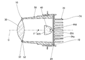
- FIG. 1 is a cross-sectional view showing a schematic configuration example of a vehicle lamp according to a first embodiment of the present invention
- FIG. FIG. 2 is a cross-sectional view taken along line AA shown in FIG. 1
- 2 is a cross-sectional view taken along line BB shown in FIG. 1
- FIG. FIG. 4 is an exploded perspective view of the light guide, the substrate, and the heat sink as seen obliquely from the front
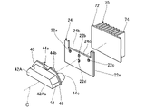
- FIG. 4 is an exploded perspective view of the light guide, the substrate, and the heat sink when viewed obliquely from behind
- It is a front view of a board
- 7 is a cross-sectional view taken along line CC shown in FIG. 6;
- FIG. 11 is a cross-sectional view taken along line DD shown in FIG. 10; FIG. It is an enlarged view around the base plate of 2nd Embodiment of this invention. It is a front view of a board
- FIG. 16 is a cross-sectional view taken along line FF shown in FIG. 15; It is a front view of the board
- FIG. 1 is a cross-sectional view showing a schematic configuration example of a vehicle lamp according to the present embodiment.
- 2 is a sectional view taken along line AA shown in FIG. 1
- FIG. 3 is a sectional view taken along line BB shown in FIG.
- the vehicle lamp 100 is used as a headlamp provided at the front end of the vehicle. Headlights are generally provided in front of the vehicle in the left and right directions. In this specification, “right” means the right side in the traveling direction of the vehicle, and “left” means the left side in the traveling direction of the vehicle. Each of the left and right headlamps has the same configuration, except that the shape is generally symmetrical in the left-right direction. Therefore, in this embodiment, one headlamp will be described.
- the vehicle lamp 100 of this embodiment mainly includes a housing 101 and a projector-type lamp unit 10 housed in the housing 101 .
- the housing 101 includes a lamp body 102 made of resin and a translucent cover 104 through which light from the lamp unit 10 is transmitted.
- the light-transmitting cover 104 is fixed to the lamp body 102 so as to close the front opening of the lamp body 102 .
- the lamp unit 10 is housed in a lamp chamber formed by a lamp body 102 and a translucent cover 104 with the optical axis adjusted so that the longitudinal direction of the lamp unit 10 substantially coincides with the longitudinal direction of the vehicle. 2 and 3, illustration of the housing 101 is omitted.
- the lamp unit 10 includes light sources 22a, 22b, 22c, and 22d, a common substrate 24 on which the light sources 22a, 22b, 22c, and 22d are mounted, a light guide 40, a projection lens 30, and a heat sink 70. Provided as a main component.
- the lamp unit 10 emits light from the light sources 22 a , 22 b , 22 c , 22 d through the light guide 40 and the projection lens 30 toward the front of the lamp unit 10 .
- the substrate 24 is made of metal, such as aluminum.
- the substrate 24 is supported by the lens holder 50 while being arranged so as to extend along a vertical plane perpendicular to the optical axis C of the projection lens 30 .
- the optical axis C is an axis extending in the front-rear direction of the lamp unit 10 .
- FIG. 4 is an exploded perspective view of the light guide 40, the substrate 24, and the heat sink 70 when viewed obliquely from the front
- FIG. 5 is an exploded perspective view of the light guide 40, the substrate 24, and the heat sink 70 when viewed obliquely from the rear.
- the light source 22a is arranged on the right side of the light source 22b and the light source 22c is arranged on the left side of the light source 22b with a space therebetween. Placed below C.
- the light sources 22a, 22b, 22c, and 22d are phosphor-type LEDs (Light Emitting Diodes) that emit white light, and are arranged with their vertically long rectangular light emitting surfaces directed forward.
- the four light sources 22a, 22b, 22c, and 22d are electrically connected to connectors (not shown) via conductive patterns (not shown) provided on the substrate 24.
- a connector is provided at the center of the lower end on the front surface of the substrate 24, and when a power supply side connector (not shown) is attached to the connector, power is supplied to the light sources 22a, 22b, 22c, and 22d.
- the light sources 22a, 22b, 22c, and 22d are turned on.
- three light sources 22a, 22b, and 22c are turned on when the low beam light distribution pattern is formed, and the remaining one light source 22d is used when the high beam light distribution pattern is formed. Lights up additionally when
- the heat sink 70 radiates heat generated from the light sources 22a, 22b, 22c, and 22d and transmitted from the substrate 24. As shown in FIG.
- the heat sink 70 is made of metal, such as aluminum.
- a heat sink 70 is arranged on the back surface 24 a of the substrate 24 .
- the heat sink 70 mainly includes a base plate 72 extending along a vertical plane perpendicular to the optical axis C of the projection lens 30, and a plurality of radiation fins 74 extending rearward from the base plate 72 along the vertical plane.
- the base plate 72 is arranged on the back surface 24a of the substrate 24, and the radiation fins 74 are arranged in parallel on the surface of the base plate 72 opposite to the back surface 24a side with a horizontal gap therebetween.
- the heat sink 70 is supported by the lens holder 50 together with the substrate 24 while the front surface of the base plate 72 is in surface contact with the back surface 24 a of the substrate 24 .
- the support of the substrate 24 and the heat sink 70 with respect to the lens holder 50 is performed by mechanical fastening.
- the substrate 24 and the heat sink 70 are fixed to the lens holder 50 by screwing them at two locations on the left and right sides of the lens holder 50 .
- the radiation fins 74 are arranged in parallel with a gap on the surface of the base plate 72 opposite to the substrate 24 side.
- the projection lens 30 is arranged in front of the light sources 22a, 22b, 22c, and 22d.
- the projection lens 30 has a rearwardly convex entrance surface and a forwardly convex exit surface, and the projection lens 30 is a biconvex aspherical lens.
- a rear focal point F of the projection lens 30 is positioned near or on a first exit surface 42A of the light guide 40, which will be described later.
- the light whose divergence angle is adjusted by the projection lens 30 is emitted forward from the vehicle lamp 100 through the translucent cover 104 .
- the projection lens 30 is made of resin such as colorless and transparent acrylic.
- the projection lens 30 is supported by the lens holder 50 at the outer peripheral flange portion 32 of the projection lens 30 .
- the lens holder 50 is a cylindrical member extending in the front-rear direction of the lamp unit 10, and is made of resin such as opaque polycarbonate.
- An annular lens support portion 52 to which the outer peripheral flange portion 32 of the projection lens 30 is fixed is provided at the front end portion of the lens holder 50 .
- the projection lens 30 is fixed to the lens holder 50 by laser welding, for example, with the outer peripheral flange portion 32 pressed against the lens support portion 52 from the front side.
- the lens supporting portion 52 is provided with a pair of upper and lower positioning pins (not shown), and the outer peripheral flange portion 32 of the projection lens 30 is provided with positioning holes (not shown) and positioning grooves (not shown) so as to face the respective positioning pins. is provided. By engaging the upper positioning pin with the positioning hole and the lower positioning pin with the positioning groove, the projection lens 30 is positioned with respect to the lens holder 50 in a direction perpendicular to the front-rear direction of the lamp unit 10 .
- a light guide 40 is arranged between the projection lens 30 and the light sources 22a, 22b, 22c, 22d.
- the light guide 40 is, for example, a primary lens, and guides the light from the light sources 22 a , 22 b , 22 c , 22 d to enter the projection lens 30 .
- the light guide 40 is made of resin such as colorless and transparent polycarbonate.
- the light guide 40 includes a first emission surface 42A for emitting light forming the low-beam light distribution pattern, and a first emission surface 42A for emitting light forming the additional light distribution pattern. and a second exit surface 42B for exiting.
- the additional light distribution pattern is a light distribution pattern added to the low beam light distribution pattern when forming the high beam light distribution pattern.
- the first emission surface 42A is positioned above the front surface of the light guide 40 and is formed to extend along the rear focal plane of the projection lens 30. As shown in FIG. As shown in FIG. 4, the first emission surface 42A has a laterally long rectangular outer shape with chamfered left and right upper corners. A lower edge 42Aa of the first exit surface 42A extends horizontally in a staggered manner so as to pass through the vicinity of the rear focus F of the projection lens 30 above.
- the second emission surface 42B is located below the front surface of the light guide 40 .
- the second exit surface 42B is located slightly behind the vertical plane perpendicular to the optical axis C of the projection lens 30 at a position a certain distance behind the lamp unit 10 from the rear focal plane of the projection lens 30. It extends along an inclined plane.
- the second emission surface 42B has a substantially oblong elliptical outer shape with the upper part missing. Most of the second exit surface 42B is located below the optical axis C. As shown in FIG.
- the light guide 40 has a block portion 42 extending rearward while substantially maintaining the outer shape of the first emission surface 42A.
- the lower surface of the block portion 42 is formed as a connection surface 42C that horizontally extends rearward from the lower edge 42Aa of the first emission surface 42A to the upper edge 42Ba of the second emission surface 42B.
- the light guide 40 has four incident surfaces 44a, 44b, 44c, 44d on which light from each of the four light sources 22a, 22b, 22c, 22d is incident. Similar to the arrangement of light sources 22a, 22b, 22c, 22d, entrance surface 44a is spaced to the right of entrance surface 44b and entrance surface 44c is spaced to the left of entrance surface 44b, and entrance surface 44b receives light from projection lens 30.
- the incident surface 44d is located below the optical axis C above the axis C. As shown in FIG.
- the incident surfaces 44 a , 44 b , 44 c are positioned on the front side with respect to each of the three light sources 22 a , 22 b , 22 c and on the rear side with respect to the block portion 42 .
- the incident surface 44d is positioned on the front side with respect to the light source 22d and on the rear side with respect to the second emission surface 42B.
- the block portion 42 directly or totally reflects the light incident from the incident surfaces 44a, 44b, and 44c and then guides it to the first output surface 42A. 1 leading to the exit surface 42A.
- a portion of the light guide 40 excluding the block portion 42 directly or totally reflects the light from the entrance surface 44d and then guides it to the second exit surface 42B.
- outer peripheral flange portions 46 are provided on the upper portion and both left and right side portions of the rear end portion of the block portion 42 .
- the outer peripheral flange portion 46 extends along a vertical plane orthogonal to the optical axis C.
- the light guide 40 is accommodated in the inner space of the lens holder 50 and supported by the lens holder 50 at the outer peripheral flange portion 46 .
- the lens holder 50 is provided with a translucent body support portion 54 extending along the outer peripheral flange portion 46 of the light guide 40 .
- the light guide 40 is fixed to the lens holder 50 by laser welding, for example, in a state where the outer peripheral flange portion 46 is pressed against the rear surface of the transparent body support portion 54 from the rear side.
- a pair of left and right positioning pins (not shown) are provided in the translucent body support portion 54 , and a pair of left and right positioning holes are provided in the outer peripheral flange portion 46 . By engaging the positioning pin with the positioning hole, the light guide 40 is positioned with respect to the lens holder 50 in a direction orthogonal to the unit front-rear direction.
- FIG. 6 is a front view of the substrate 24.
- FIG. 6 the portion of the base plate 72 that overlaps the substrate 24 and the incident surfaces 44a, 44b, 44c, and 44d are indicated by dashed lines.
- the light sources 22a, 22b, 22c, and 22d are positioned inside the outer peripheries of the incident surfaces 44a, 44b, 44c, and 44d.
- a part of the substrate 24 is notched, and the substrate 24 is provided with a slit-shaped opening 24b.
- the aperture 24b is elongated in the horizontal direction along which the three light sources 22a, 22b, and 22c are aligned, and is longer than the space between the light sources 22a and 22c.
- the opening 24b is provided on the side opposite to the light source 22d with respect to the three light sources 22a, 22b, and 22c.
- the opening 24 b provides the base plate 72 with a non-overlapping portion 72 a that does not overlap the substrate 24 .
- the non-overlapping portion 72 a is a portion of the base plate 72 exposed from the substrate 24 .
- FIG. 7 is a cross-sectional view taken along line CC shown in FIG. In FIG. 7, the opening 24b is indicated by a dashed line.
- a first space 201 and a second space 203 are provided between the light source 22a side and the incident surface 44a of the light guide 40 on which the light from the light source 22a is incident.
- the first space 201 and the second space 203 are channels through which gas can flow.
- the first space 201 and the second space 203 are also provided between the light source 22b side and the incident surface 44b of the light guide 40 and between the light source 22c side and the incident surface 44c of the light guide 40, respectively. Configuration. Therefore, the first space 201 and the second space 203 on the side of the light source 22a are used for explanation.
- the configurations of the incident surfaces 44b and 44c are the same as the configuration of the incident surface 44a described below.
- a concave portion 441a recessed toward the projection lens 30 is provided on the incident surface 44a.
- the concave portion 441a faces the substrate 24, the light source 22a, and the non-overlapping portion 72a. Therefore, when the substrate 24 is viewed from the front, the recess 441a overlaps the substrate 24, the edge 24c of the substrate 24, the light source 22a, and the non-overlapping portion 72a.
- the incident surface 44a includes a first region 441b including part of the outer periphery of the incident surface 44a and a second region 441c including another part of the outer periphery of the incident surface 44a.
- the first region 441b is provided below the second region 441c.
- the first region 441b and the second region 441c are provided on the same plane outside the recess 441a, but may be provided on different planes.
- the first area 441b and the second area 441c are located closer to the projection lens 30 than the light emitting surface of the light source 22a.
- the first region 441b faces the substrate 24, and a first space 201 is provided between the first region 441b and the substrate 24. Therefore, when the substrate 24 is viewed from the front, the first region 441b overlaps the first space 201 and the substrate 24, and the substrate 24 is arranged on the opposite side of the first space 201 from the first region 441b.
- the second region 441c faces the non-overlapping portion 72a, and a second space 203 is provided between the second region 441c and the non-overlapping portion 72a. Therefore, when the substrate 24 is viewed from the front, the second region 441c overlaps the second space 203 and the non-overlapping portion 72a, and the substrate 24 is located on the opposite side of the second space 203 from the second region 441c. In this arrangement, the non-overlapping portion 72a is arranged, and the second space 203 is in contact with the base plate 72. As shown in FIG.
- the second space 203 is provided above the first space 201 and communicates with the first space 201 via the recess 441a. Therefore, a recess 441a is provided between the first space 201 and the second space 203, and when the substrate 24 is viewed from the front, the boundary between the first space 201 and the second space 203 overlaps the recess 441a. It doesn't have to be. Since the non-overlapping portion 72a is farther from the incident surface 44a than the substrate 24, the second space 203 is wider than the first space 201 in the direction of the optical axis C, which is the direction in which light is emitted from the light source 22a.
- the second space 203 is longer than the first space 201 in the vertical direction and wider than the first space 201 in the direction of the optical axis C and in the width direction of the substrate 24, which is the direction orthogonal to the vertical direction.
- the second space 203 continues to the space above the light guide 40 in the internal space of the lamp chamber.
- the space above is wider than the second space 203 . Since the second space 203 communicates with the first space 201 through the recess 441a as described above, the light source 22a and the edge 24c are located between the first space 201 and the second space 203.
- each light distribution pattern will be described as being formed on a virtual vertical screen arranged 25 m ahead of the vehicle.
- the light distribution pattern for low beam will be explained.
- Most of the light from the light source 22b that has entered the light guide 40 through the entrance surface 44b directly reaches the first emission surface 42A, and is emitted from the first emission surface 42A toward the projection lens 30 as obliquely downward light. .
- Part of the light from the light source 22b reaches the first emission surface 42A after being totally reflected by the connection surface 42C, and is emitted toward the projection lens 30 as obliquely upward light from the first emission surface 42A.
- Light from the light sources 22a, 22b, and 22c forms a low-beam light distribution pattern.
- the low-beam light distribution pattern is a light distribution pattern formed by reversely projecting the projection image formed on the first emission surface 42A by the projection lens 30 .
- the low-beam light distribution pattern is formed in an outer shape that roughly corresponds to the outer shape of the first emission surface 42A. Since the light guide 40 is arranged so that the first emission surface 42A is located on the rear focal plane of the projection lens 30, in the light distribution pattern for low beam, the lower edge 42Aa of the first emission surface 42A cuts off the line. is formed.
- a pair of light from the light source 22 d that has entered the light guide 40 through the entrance surface 44 d is emitted from the second exit surface 42 B and reaches the projection lens 30 .
- the light from the light source 22d forms an additional light distribution pattern positioned above the cutoff line of the low beam light distribution pattern with respect to the low beam light distribution pattern.
- the additional light distribution pattern is a light distribution pattern formed by reversely projecting a projection image formed on the rear focal plane of the projection lens 30 by the light emitted from the second emission surface 42B by the projection lens 30. be.
- the top position of the projection image is defined by the bottom edge 42Aa of the first emission surface 42A
- the bottom position of the additional light distribution pattern is defined by the cutoff line. Therefore, the high-beam light distribution pattern is formed by connecting the low-beam light distribution pattern and the additional light distribution pattern without a gap.
- the heat from the light source 22a warms the gas between the light source 22a and the incident surface 44a, and the warmed gas rises. Since the second space 203 is provided above the first space 201 , the heated gas flows from the first space 201 to the second space 203 . Since the width of the second space 203 is wider than the width of the first space 201, the gas flows from the first space 201 to the second It becomes easy to flow into the space 203 and to flow easily through the second space 203 . Also, the gas flows from the second space 203 to the space above the light guide 40 . Since the upper space is wider than the second space 203, the gas easily flows from the second space 203 to the upper space. When the gas flows in this manner, heat accumulation is suppressed between the light source 22a and the incident surface 44a.
- the light source and the light guide are brought closer to each other so that most of the light from the light source is incident on the light guide, thereby increasing the light utilization efficiency.
- the heat from the light source tends to accumulate between the light source and the light guide as the light source and the light guide are brought closer to each other.
- the light guide is made of resin, heat accumulated between the light source and the light guide may deform the light guide. If the light guide is deformed, the course of the light traveling inside the light guide and the course of the light traveling from the light guide to the projection lens change, and are formed by the light emitted from the vehicle lamp.
- the light distribution pattern may change into an unintended shape.
- the vehicle lamp 100 of this embodiment includes a substrate 24, a light source 22a mounted on the substrate 24, a projection lens 30 arranged in front of the light source 22a, and an incident surface 44a on which light from the light source 22a is incident. and a light guide 40 that is disposed between the light source 22a and the projection lens 30 and emits light toward the projection lens 30, and on the light source 22a side of the entrance surface 44a,
- a first space 201 is provided between a first region 441b including a part of the outer peripheral edge of the incident surface 44a and the substrate 24, communicates with the first space 201, and extends outside the incident surface 44a of the incident surface 44a.
- a second space 203 is provided in contact with a second region 441c including another portion of the periphery, and the width of the second space 203 is wider than the width of the first space 201 in the direction of light emitted from the light source 22a.
- the width of the second space 203 is wider than the width of the first space 201. Therefore, compared to the case where the width of the second space 203 is the same as the width of the first space 201, the gas is 203 can be facilitated.
- the gas flows easily, heat is less likely to accumulate between the light source 22a and the incident surface 44a, and deformation of the light guide 40 due to heat can be suppressed.
- the deformation is suppressed, the light traveling inside the light guide 40 and the light traveling from the light guide 40 to the projection lens 30 can be suppressed from traveling in unintended directions, and light distribution in unintended shapes can be achieved. Pattern changes can be suppressed.
- the vehicle lamp 100 further includes a heat sink 70 including a base plate 72 on which the substrate 24 is arranged.
- the base plate 72 includes a non-overlapping portion 72a that does not overlap the substrate 24. It is provided between the second region 441c and the non-overlapping portion 72a.
- the second space 203 since the second space 203 is in contact with the base plate 72, the heat between the light source 22a and the incident surface 44a is reduced from the second space 203 compared to when the second space 203 is not in contact with the base plate 72. It can be easily transmitted to the base plate 72 that is in contact with the second space 203 . Therefore, deformation of the light guide 40 due to heat can be suppressed in the second region 441c.
- the substrate 24 is not formed in the second space 203, the gas flowing in the second space 203 is less likely to receive radiant heat from the substrate 24 than in the first space 201, and the temperature rise of the gas can be suppressed. Note that the second space 203 does not have to be provided between the second region 441c of the incident surface 44a and the non-overlapping portion 72a.
- the substrate 24 is arranged non-horizontally, and the second space 203 is provided above the first space 201 .
- the gas warmed by the heat between the light source 22a and the incident surface 44a rises.
- the warmed gas flows from the first space 201 to the second space 203 wider than the first space 201 .
- the gas can flow more easily, and in natural air cooling, a heat buildup can be suppressed.
- the substrate 24 is not arranged non-horizontally, and the second space 203 does not have to be provided above the first space 201 .
- the light travels above the light guide 40 . Therefore, the temperature on the upper side tends to be higher than on the lower side of the light guide 40 where light travels only when the high-beam light distribution pattern is formed. Since the upper side of the light guide 40 having a high temperature is in contact with the second space 203, the heat from the light guide 40 is transmitted to the gas flowing through the second space 203 and rises together with the gas. Therefore, the temperature rise on the upper side of the light guide 40 is suppressed.
- the second space 203 of the present embodiment is provided between the second region 441c of the incident surface 44a and the non-overlapping portion 72a, it is not limited to this, and the second space 203 will be described below. A modification of is explained.
- FIG. 8 is a diagram showing a first modified example of the second space 203.
- the base plate 72 is not arranged on the opposite side of the second region 441c via the second space 203, and the second space 203 is not in contact with the base plate 72.
- the second region 441c may face the rear surface of the lamp body 102. As shown in FIG.
- FIG. 9 is a diagram showing a second modified example of the second space 203.
- the substrate 24 of this modified example includes a body portion 24d including a region facing the first region 441b of the incident surface 44a, and an extension portion 24e facing the second region 441c of the incident surface 44a and thinner than the body portion 24d.
- the extending portion 24e is a portion obtained by cutting out a portion of the main body portion 24d, connects with the main body portion 24d, and extends upward from the main body portion 24d.
- the extended portion 24e covers the base plate 72, and the non-overlapping portion 72a is not provided in this modification.
- the boundary between the main body portion 24d and the extension portion 24e overlaps the concave portion 441a provided in the incident surface 44a.
- the second space 203 of this modified example is provided between the second region 441c of the incident surface 44a and the extending portion 24e and is not in contact with the base plate 72 .
- the light sources 22a, 22b, 22c, and 22d are provided in the body portion 24d. When the substrate 24 is viewed from the front, the upper edges of the light sources 22a, 22b, 22c, and 22d overlap the upper edge of the main body 24d.
- the substrate 24 can be wider than when the extending portion 24e is not provided. Note that the configuration of this modified example is not essential.
- FIG. 10 is a view showing a modification of the heat sink 70, and is a cross-sectional view taken along line AA shown in FIG.
- FIG. 11 is a cross-sectional view taken along line DD shown in FIG.
- the base plate 72 has a plurality of base plate pieces 721 arranged on the rear surface 24a of the substrate 24 in a horizontal direction with a space therebetween. Adjacent base plate pieces 721 are not connected to each other. A radiation fin 74 is arranged on each of the base plate pieces 721 .
- the radiating fins 74 provided on each of the base plate pieces 721 adjacent to each other are connected to each other by connecting portions 74a that are integral with the radiating fins 74, and the adjacent base plate pieces 721 are configured as one unit.
- the heat radiating fins 74 that are connected to each other are the heat radiating fin 74 that is positioned closest to the other base plate piece 721 of one base plate piece 721 in the base plate pieces 721 that are adjacent to each other, and the heat radiating fin 74 that is positioned closest to the other base plate piece 721 of the other base plate pieces 721 . and the radiation fin 74 located on the piece 721 side.
- a connecting portion 74a is provided on the heat radiation fin 74 as described above.
- the connecting portion 74a has a rectangular outer shape, and extends from the upper end to the lower end of each main surface of the radiation fins 74 that are adjacent to each other in the vertical direction.
- an exposed region 24f exposed from the base plate 72 of the back surface 24a of the substrate 24 is provided between the base plate pieces 721 adjacent to each other. Therefore, the substrate 24 is provided with an exposed region 24f exposed from the base plate 72 of the back surface 24a.
- the exposed region 24f is a region exposed between the mutually adjacent base plate pieces 721 on the back surface 24a, and is a region exposed between the mutually adjacent heat radiation fins 74 on the mutually adjacent base plate pieces 721 on the back surface 24a. But also.
- the exposed region 24f may be exposed at least partly between the mutually adjacent radiation fins 74 on the rear surface 24a.
- the exposed region 24f is located on the side opposite to the light sources 22a, 22b, and 22c with respect to the substrate 24, and extends from the upper end to the lower end of the substrate 24 in the vertical direction. Therefore, there are three exposed regions 24f, and each of the exposed regions 24f overlaps the light sources 22a, 22b, 22c and the incident surfaces 44a, 44b, 44c when the substrate 24 is viewed from the front.
- the exposed region 24f that overlaps the light source 22b and the incident surface 44b also overlaps the light source 22d and the incident surface 44d. Therefore, when the substrate 24 is viewed from the front, the base plate pieces 721 adjacent to each other are arranged in parallel with a space therebetween so as not to overlap the light sources 22a, 22b, 22c, and 22d.
- the heat sink 70 is provided with a third space 205 in contact with the exposed region 24f, the base plate 72, and the radiation fins 74 adjacent to each other.
- the third space 205 is a heatsink-side space provided between the radiation fins 74 adjacent to each other. Since there are three exposed regions 24f, three third spaces 205 are also provided. The configuration of each third space 205 is the same. Since the connecting portion 74a is provided in this modified example, the third space 205 is a slit surrounded by the exposed region 24f, the adjacent base plate pieces 721, the adjacent radiation fins 74, and the connecting portion 74a. Also, the third space 205 is open at the upper end side and the lower end side.
- the third space 205 opens at the rear when the connecting portion 74a is not provided or when the connecting portion 74a is provided in a part between the upper end and the other end of the radiation fins 74 .
- the third space 205 extends vertically from the upper end to the lower end of the base plate 72 .
- the third space 205 is a channel through which gas can flow.
- the third space 205 overlaps the substrate 24 when the substrate 24 is viewed from the front. Further, when the substrate 24 is viewed from the front, the respective third spaces 205 overlap the light sources 22a, 22b, 22c and 22d and the incident surfaces 44a, 44b, 44c and 44d. As described above, the exposed region 24f that overlaps the light source 22b also overlaps the light source 22d, so the third space 205 that overlaps the light source 22b and the incident surface 44b also overlaps the light source 22d and the incident surface 44d. In the horizontal direction, the width of each of the third spaces 205 is wider than the width of the light sources 22a, 22b, 22c, 22d.
- each of the third spaces 205 is narrower than the maximum width of the incident surfaces 44a, 44b, 44c, and 44d.
- Each width of the third space 205 may be the same as the width of the light sources 22a, 22b, and 22c, or may be narrower than the width.
- Each width of the third space 205 may be the same as the maximum width of the incident surfaces 44a, 44b, 44c, and 44d, or may be wider than the width.
- the third space 205 overlaps the substrate 24 when viewed from the front and merges with the second space 203 .
- the heat sink 70 of this modified example includes the exposed region 24f exposed from the base plate 72 at least partially between the heat radiation fins 74 adjacent to each other on the back surface 24a of the substrate 24, the base plate 72, and the heat sink 74 adjacent to each other.
- a third space 205 in contact with the radiation fins 74 is provided between adjacent radiation fins 74 .
- the substrate 24 is made of metal, and the thermal conductivity of the metal is higher than that of the resin compared to the case where the substrate 24 is made of resin. Heat may be readily conducted through substrate 24 to base plate 72 . Since the heat transmitted to the base plate 72 is radiated from the radiation fins 74, the substrate 24 can be easily cooled. Further, in the vehicle lamp 100, the exposed region 24f is in contact with the third space 205, so heat is also directly radiated from the exposed region 24f, which is a part of the substrate 24. FIG. In this case, the substrate 24 can be cooled more easily than if the heat was not dissipated directly from the substrate 24 .
- the heat from the light source 22a can be easily conducted to the substrate 24, and the cooling efficiency of the light source 22a can be improved. Further, when the light source 22a is cooled, the wavelength of the light emitted from the light source 22a can be suppressed from shifting due to heat, and light of a predetermined color can be emitted. Further, when the heat from the light source 22a is transmitted to the substrate 24, deformation of the light guide 40 due to heat can be further suppressed. Note that the configuration of this modified example is not essential.
- the third space 205 merges with the second space 203 .
- gas flows from the third space 205 to the second space 203 and if the gas flowing through the third space 205 is faster than the gas flowing through the second space 203, the gas flowing through the second space 203 will flow into the third space 205. is drawn in by the gas joining the second space 203 from the . This increases the speed of the gas flowing through the second space 203 . Therefore, the light guide 40 can be cooled.
- the gas flowing in the second space 203 is faster than the gas flowing in the third space 205
- the gas flowing in the third space 205 is drawn by the gas flowing in the second space 203
- the gas flowing in the third space 203 is drawn by the gas flowing in the second space 203.
- the velocity of the gas flowing through space 205 increases. Therefore, the heat sink 70 can be cooled.
- the third space 205 is in contact with the exposed region 24 f of the back surface 24 a of the substrate 24 .
- the substrate 24 can be cooled via the exposed region 24f. Note that the third space 205 does not have to merge with the second space 203 .
- the third space 205 overlaps the light source 22a.
- heat from the light source 22a can be more easily transferred to the gas flowing through the third space 205 via the substrate 24 than when the third space 205 does not overlap the light source 22a.
- At least part of the third space 205 may overlap the light source 22a.
- the third space 205 overlapping the light source 22a has been described here, the same applies to the third space 205 overlapping other light sources. Further, when the substrate 24 is viewed from the front, the third space 205 does not have to overlap the light source 22a.
- the third space 205 does not need to be provided in three places, and when the substrate 24 is viewed from the front, it is provided so as to overlap with any one of the light source 22a, the light sources 22b, 22d, and the light source 22c. good too. Further, when the substrate 24 is viewed from the front, the third space 205 may be provided so as not to overlap the light sources 22a, 22b, 22c, and 22d. The third space 205 may overlap at least part of the incident surface 44a. When the substrate 24 is cooled, heat from the light source 22a is easily transferred to the substrate 24 .
- the heat from the light source 22a is less likely to be transmitted to the incident surface 44a than when the third space 205 does not overlap the incident surface 44a. Heat is less likely to accumulate between 22a and incident surface 44a. Thereby, deformation of the light guide 40 due to the heat can be suppressed.
- the deformation of the light guide 40 is suppressed, the light traveling inside the light guide 40 and the light emitted from the light guide 40 can be suppressed from traveling in unintended directions. Pattern changes can be suppressed.
- the incident surface 44a has been described above, the other incident surfaces are the same.
- the exposed region 24 f may be a portion of the back surface 24 a of the substrate 24 that is exposed from the base plate 72 . Therefore, the exposed region 24 f may be exposed through a through hole provided in the base plate 72 . Also, the base plate pieces 721 adjacent to each other are not connected to each other, but may be connected so as to provide an exposed region 24f.
- the non-overlapping portion 72d may be the through hole described above.
- FIG. 12 is an enlarged view around the base plate 72 of this embodiment.
- the configuration of the connecting portion 74a is different from that of the connecting portion 74a shown in FIG. 10 of the first embodiment.
- the connecting portion 74a of the present embodiment has a hexagonal outer shape and inner shape, and is hollow.
- the connecting portion 74a extends from the upper end to the lower end of each main surface of the radiation fins 74 that are adjacent to each other in the vertical direction.
- the connecting portion 74a is integrated with the heat radiating fins, but may be separate.
- the connecting portion 74a increases the surface area of the heat radiating fins 74 .
- the shape of the connecting portion 74a described above is not particularly limited.
- the connecting portion 74a may be provided between the upper end and the other end of the main surface.
- the connecting portion 74a may not be provided, and the radiation fins 74 may be disconnected from each other.
- the respective heat radiation fins 74 are not connected, but may be connected as described above.
- FIG. 13 is a front view of the substrate 24.
- portions of the base plate piece 721 overlapping the substrate 24 and incident surfaces 44a, 44b, 44c, and 44d are indicated by broken lines.
- Base plate piece 721 is shown slightly smaller than substrate 24 for ease of understanding.
- the substrate 24 of the present embodiment is different from the first embodiment in that the shape of the substrate 24 is a horizontally long rectangular shape, a part of the substrate 24 is not cut away, and the substrate 24 is not provided with an opening 24b. is different.
- FIG. 14 is a cross-sectional view taken along line EE shown in FIG.
- the first space 201 which is the light source side space, is provided between the light source 22a side and the incident surface 44a of the light guide 40 into which the light from the light source 22a is incident.
- the substrate 24 of this embodiment is not provided with the opening 24b described in the first embodiment. Therefore, the second region 441c of the light guide 40 faces the substrate 24, which is different from the first embodiment.
- the second space 203 of this embodiment is provided between the second region 441c and the substrate 24, which is different from the first embodiment. Therefore, when the substrate 24 is viewed from the front, the second area 441c overlaps the second space 203 and the substrate 24, and the substrate 24 is arranged on the opposite side of the second area 441c via the second space 203. .
- the widths of the first space 201 and the second space 203 are the same in the direction of the optical axis C, which is the direction in which light is emitted from the light source 22a. .
- the width of the first space 201 is narrower than the width of the third space 205 in the direction in which light is emitted from the light source 22a. 205.
- the substrate 24 Since the substrate 24 is made of metal, the heat from the light source 22a is transmitted to the substrate 24 more than the gas in the first space 201 and the second space 203 between the light source 22a and the incident surface 44a.
- the heat transmitted to the substrate 24 is transmitted from the base plate piece 721 to the radiation fins 74, and is radiated from the radiation fins 74 and the connecting portion 74a.
- the exposed region 24f is in contact with the third space 205, heat is also directly radiated from the exposed region 24f, which is a part of the substrate 24.
- the substrate 24 can be cooled more easily than when heat is not directly radiated from the substrate 24 .
- the gas flows through the third space 205, the gas comes into contact with the exposed region 24f.
- substrate 24 is cooled more than if the gas does not contact exposed regions 24f.
- the heat from the light source 22a is easily transferred to the substrate 24, and the light source 22a is cooled.
- the light source 22a has been described above, the same applies to the heat from the other light sources 22b, 22c, and 22d.
- the light source is cooled by the heat radiation from the heat radiation fins, but there is a demand to make it easier to cool the light source and improve the cooling efficiency of the light source.
- the vehicle lamp 100 of this embodiment includes a metal substrate 24, a light source 22a mounted on the surface of the substrate 24, and a heat sink 70 arranged on the back surface 24a of the substrate 24.
- the heat sink 70 is mounted on the back surface 24a.
- a plurality of radiation fins 74 arranged in parallel at intervals on the surface of the base plate 72 opposite to the substrate 24 side.
- An exposed region 24 f exposed from the base plate 72 in at least a portion between the adjacent heat radiation fins 74 , the base plate 72 , and a third space 205 contacting the mutually adjacent heat radiation fins 74 are provided between the mutually adjacent heat radiation fins 74 . be done.
- the substrate 24 is made of metal.
- the heat from the light source 22a can be easily transmitted to the base plate 72 via the substrate 24, because the thermal conductivity of the metal is higher than that of the resin, compared to the case where the substrate 24 is made of resin. . Since the heat transmitted to the base plate 72 is radiated from the radiation fins 74, the substrate 24 can be easily cooled.
- the exposed region 24f is in contact with the third space 205, so heat is also directly radiated from the exposed region 24f, which is a part of the substrate 24. FIG. In this case, the substrate 24 can be cooled more easily than if the heat was not dissipated directly from the substrate 24 .
- the heat from the light source 22a can be easily conducted to the substrate 24, and the cooling efficiency of the light source 22a can be improved. Further, when the light source 22a is cooled, the wavelength of the light emitted from the light source 22a can be suppressed from shifting due to heat, and light of a predetermined color can be emitted.
- the third space 205 overlaps the light source 22a when the substrate 24 is viewed from the front.
- the gas flowing through the third space 205 can easily cool the region of the substrate 24 that overlaps the light source 22a. Cooling the area may improve the cooling efficiency of the light source 22a.
- the 3rd space 205 may overlap with at least one part of the light source 22a.
- the third space 205 does not have to overlap the light source 22a.
- the width of the third space 205 which is the space on the heat sink side, is wider than the width of the light source 22a.
- the width of the third space 205 when the width of the third space 205 is widened, the width of the exposed region 24f is widened, heat is easily transferred from the exposed region 24f to the third space 205, and the substrate 24 is easily cooled.
- the width of the third space 205 increases, the gas can easily flow through the third space 205 .
- the gas flows easily, it becomes difficult for heat to accumulate in the third space 205, and the substrate 24 is easily cooled.
- the heat from the light source 22a can be easily transferred to the substrate 24, and the cooling efficiency of the light source 22a can be improved.
- the area around the light source 22a in the substrate 24 can be cooled, and when the area is cooled, the heat from the light source 22a is diffused to the area, so that the cooling efficiency of the light source 22a is further improved.
- the width of the third space 205 may be equal to or less than the width of the light source 22a.
- the heat radiation fins 74 provided on each of the adjacent base plate pieces 721 are connected to each other.
- the base plate pieces 721 adjacent to each other with the heat radiating fins 74 interposed therebetween are configured as one unit.
- the number of man-hours for attaching the heat sink 70 can be reduced as compared to the case where the radiation fins 74 are not connected.
- the radiation fins 74 may not be connected to each other.
- the vehicle lamp 100 of this embodiment has an incident surface 44a on which light from the light source 22a is incident, and further includes a light guide 40 arranged in front of the light source 22a to guide light. is viewed from the front, the third space 205 overlaps the incident surface 44a.
- the third space 205 in this embodiment overlaps part of the entrance surface 44a, it may overlap at least part of the entrance surface 44a.
- the heat from the light source 22a is easily transferred to the substrate 24. Therefore, when the third space 205 overlaps at least a portion of the incident surface 44a, heat from the light source 22a is less likely to be transmitted to the incident surface 44a than when the third space 205 does not overlap the incident surface 44a. In addition, heat is less likely to accumulate between the light source 22a and the incident surface 44a, and deformation of the light guide 40 including the incident surface 44a due to the heat can be suppressed. When the deformation of the light guide 40 is suppressed, the light traveling inside the light guide 40 and the light emitted from the light guide 40 can be suppressed from traveling in unintended directions. Pattern changes can be suppressed. Note that when the substrate 24 is viewed from the front, the third space 205 does not have to overlap the incident surface 44a.
- third space 205 of the present embodiment has been described as overlapping the substrate 24, there is no need to be limited to this, and a first modified example of the third space 205 will be described below. This modification differs from the third space 205 of the present embodiment in that a portion of the third space 205 extends outside the substrate 24 .
- FIG. 15 is a front view of the substrate 24 in the first modified example of this embodiment. 16 is a cross-sectional view taken along line FF shown in FIG. 15. FIG.
- the substrate 24 of this modified example has the same configuration as the substrate 24 of the first embodiment. Therefore, the substrate 24 of this modified example is provided with an opening 24b.
- the upper edges of the light sources 22a, 22b, and 22c are located below the edge 24c of the substrate 24 that contacts the lower edge of the opening 24b.
- the base plate piece 721 of the base plate 72 is provided with a non-overlapping portion 721a that does not overlap with the substrate 24 and an overlapping portion 721b that overlaps with the substrate 24 due to the opening 24b.
- the non-overlapping portion 721 a is a portion of the base plate piece 721 exposed from the substrate 24 .
- the non-overlapping portion 721a does not overlap with the incident surfaces 44a, 44b, 44c, and 44d, the incident surfaces 44a, 44b, 44c, and 44d overlap with the substrate 24, and part of the outer peripheral edges of the incident surfaces 44a, 44b, and 44c are edges. 24c. Also, the edge 24c overlaps the boundary between the non-overlapping portion 721a and the overlapping portion 721b.
- the radiation fins 74 extend to the non-overlapping portion 721a.
- the third space 205 of this modification extends to the edge 24c overlapping the boundary between the non-overlapping portion 721a and the overlapping portion 721b of the substrate 24 when the substrate 24 is viewed from the front. It is open on the 721a side.
- the third space 205 communicates through an opening with a non-overlapping portion side space 301a provided between the non-overlapping portions 721a of the base plate pieces 721 adjacent to each other.
- a radiation fin 74 extending in contact with the third space 205 extends in the non-overlapping portion 721a, and the radiation fin 74 contacts the non-overlapping portion side space 301a.
- the non-overlapping portion side space 301a is open on the substrate 24 side, above and behind.
- the third space 205 extends to the edge 24c overlapping the boundary between the non-overlapping portion 721a and the overlapping portion 721b of the substrate 24 when the substrate 24 is viewed from the front.
- the third space 205 opens on the non-overlapping portion 721a side.
- the gas flowing through the third space 205 and the gas flowing through the second space 203 join through the opening of the third space 205 and the non-overlapping portion side space 301a, and the gas flowing through the third space 205 flows through the second space 203. If faster than the gas, the gas flowing through the second space 203 will be entrained by the gas flowing through the third space 205, increasing the velocity of the gas flowing through the second space 203. Therefore, the light guide 40 can be cooled.
- the gas flowing in the second space 203 is faster than the gas flowing in the third space 205
- the gas flowing in the third space 205 is drawn by the gas flowing in the second space 203
- the gas flowing in the third space 203 is drawn by the gas flowing in the second space 203.
- the velocity of the gas flowing through space 205 increases. Therefore, the heat sink 70 can be cooled.
- the third space 205 does not have to extend to the edge 24c.
- FIG. 17 is a front view of the substrate 24 in the second modified example of the second embodiment.
- This modification differs from the base plate 72 of the present embodiment in that the base plate piece 721 is not provided and one base plate 72 is provided. Further, in this modified example, the third space 205 is provided in the non-overlapping portion 72a of the base plate 72 instead of between the base plate pieces 721 adjacent to each other, which is different from the third space 205 of the present embodiment.
- the base plate 72 of this modified example is provided with a non-overlapping portion 72a that does not overlap with the substrate 24, and the non-overlapping portion 72a is, for example, a slit.
- the non-overlapping portion 72a provides an exposed region 24f (not shown in FIG. 17) on the rear surface 24a. When the substrate 24 is viewed from the front, the exposed region 24f overlaps the non-overlapping portion 72a.
- the third space 205 is in contact with the exposed region 24f, the base plate 72, and the heat radiation fins 74 adjacent to each other.
- the third space 205 can be provided not between the base plate pieces 721 adjacent to each other, but even in one base plate 72 .
- the non-overlapping portion 72a of this modified example may be a through hole.
- the gas may flow from the first space 201 toward the second space 203 by means of a fan.
- the fan may be provided below the first space 201 for blowing air, or may be provided above the second space 203 for suction.
- the gas may flow from the second space 203 towards the first space 201 by means of a fan.
- the fan may be provided below the first space 201 for suction, or may be provided above the second space 203 for blowing air.
- the first space 201 and the second space 203 may be provided along the direction perpendicular to the direction of light emitted from the light sources 22a, 22b, and 22c, that is, along the horizontal direction.
- the first space 201 and the second space 203 may be provided on the light source 22d side.
- the non-overlapping portion 72a may be a portion of the base plate 72 that is exposed from the substrate 24 . Therefore, the non-overlapping portion 72a may be exposed not only through the opening 24b but also through a through hole provided in the substrate 24, or may be exposed above the upper edge of the rectangular substrate 24 in which the opening 24b is not provided. may be exposed by being located at
- the recess 441a may not be provided. Further, when the substrate 24 is viewed from the front, the edge 24c may overlap the edge of the recess 441a that is in contact with the second region 441c.
- the second space 203 may be the same as or shorter than the first space 201 in the vertical direction. Also, the second space 203 may have the same depth as or narrower than the first space 201 in the width direction of the substrate 24, which is the direction orthogonal to the optical axis C direction and the vertical direction.
- the light guide 40 is made of resin such as polycarbonate in the above embodiment and modification, it may be made of resin such as colorless and transparent acrylic, or colorless and transparent glass.
- the four light sources 22a, 22b, 22c, and 22d are all described as having vertically long rectangular light emitting surfaces. It may have a shaped light emitting surface.
- the low beam light source is composed of the three light sources 22a, 22b, and 22c, and the additional lighting light source is composed of the single light source 22d.
- the number of light sources is not particularly limited.
- the vehicle lamp 100 is a headlamp in the above embodiment and modification, it is not particularly limited.
- the vehicle lamp 100 may irradiate an object such as a road surface with light that forms an image.
- the direction of the emitted light from the vehicle lamp and the position where the vehicle lamp is attached to the vehicle are not particularly limited.
- the color of the light emitted from the vehicle lamp is preferably white, but is not particularly limited.
- connection portion 74a of the heat sink 70 shown in FIG. 10 of the first embodiment may have the same configuration as the connection portion 74a of the heat sink 70 of this embodiment.
- the connecting portion 74a of the heat sink 70 of the second embodiment may have the same configuration as the connecting portion 74a of the heat sink 70 shown in FIG. 10 of the first embodiment.
- the heat sink 70 of the first embodiment and its modifications may be arranged on the substrate 24 of the second embodiment and its modifications instead of the heat sink 70 of the second embodiment and its modifications.
- the heat sink 70 of the second embodiment and its modification may be arranged on the substrate 24 of the first embodiment and its modification instead of the heat sink 70 of the first embodiment and its modification.
Landscapes
- Engineering & Computer Science (AREA)
- General Engineering & Computer Science (AREA)
- Physics & Mathematics (AREA)
- Microelectronics & Electronic Packaging (AREA)
- Optics & Photonics (AREA)
- Non-Portable Lighting Devices Or Systems Thereof (AREA)
Priority Applications (4)
| Application Number | Priority Date | Filing Date | Title |
|---|---|---|---|
| US18/576,446 US12398857B2 (en) | 2021-07-07 | 2022-07-04 | Vehicular lamp |
| JP2023533126A JPWO2023282238A1 (https=) | 2021-07-07 | 2022-07-04 | |
| CN202280047829.XA CN117597543A (zh) | 2021-07-07 | 2022-07-04 | 车辆用灯具 |
| EP22837653.9A EP4368879A4 (en) | 2021-07-07 | 2022-07-04 | VEHICLE LAMP |
Applications Claiming Priority (4)
| Application Number | Priority Date | Filing Date | Title |
|---|---|---|---|
| JP2021113185 | 2021-07-07 | ||
| JP2021113184 | 2021-07-07 | ||
| JP2021-113185 | 2021-07-07 | ||
| JP2021-113184 | 2021-07-07 |
Publications (1)
| Publication Number | Publication Date |
|---|---|
| WO2023282238A1 true WO2023282238A1 (ja) | 2023-01-12 |
Family
ID=84800654
Family Applications (1)
| Application Number | Title | Priority Date | Filing Date |
|---|---|---|---|
| PCT/JP2022/026639 Ceased WO2023282238A1 (ja) | 2021-07-07 | 2022-07-04 | 車両用灯具 |
Country Status (4)
| Country | Link |
|---|---|
| US (1) | US12398857B2 (https=) |
| EP (1) | EP4368879A4 (https=) |
| JP (1) | JPWO2023282238A1 (https=) |
| WO (1) | WO2023282238A1 (https=) |
Cited By (1)
| Publication number | Priority date | Publication date | Assignee | Title |
|---|---|---|---|---|
| WO2024214795A1 (ja) * | 2023-04-11 | 2024-10-17 | 市光工業株式会社 | 車両用前照灯 |
Families Citing this family (1)
| Publication number | Priority date | Publication date | Assignee | Title |
|---|---|---|---|---|
| JP2025182912A (ja) * | 2024-06-04 | 2025-12-16 | スタンレー電気株式会社 | 車両用灯具 |
Citations (4)
| Publication number | Priority date | Publication date | Assignee | Title |
|---|---|---|---|---|
| JP2012164626A (ja) * | 2011-01-18 | 2012-08-30 | Nippon Oyo Kogaku Kk | 発光装置 |
| JP2016219723A (ja) * | 2015-05-26 | 2016-12-22 | スタンレー電気株式会社 | 光源装置及びこれを用いた照明装置 |
| JP2017199660A (ja) | 2016-04-11 | 2017-11-02 | ヴァレオ ビジョンValeo Vision | 光ビームを放出するための自動車両ヘッドライト・モジュール |
| JP2021012907A (ja) | 2019-07-04 | 2021-02-04 | 株式会社小糸製作所 | 発光素子実装用の基板及び車両用灯具 |
Family Cites Families (15)
| Publication number | Priority date | Publication date | Assignee | Title |
|---|---|---|---|---|
| DE102009008631B4 (de) * | 2009-02-12 | 2016-11-03 | Automotive Lighting Reutlingen Gmbh | Projektionsmodul für einen Kraftfahrzeugscheinwerfer |
| WO2012020597A1 (ja) | 2010-08-12 | 2012-02-16 | 日本応用光学株式会社 | 照明装置 |
| US8899803B2 (en) | 2011-11-04 | 2014-12-02 | Truck-Lite, Co., Llc | Headlamp assembly having a heat sink structure and wire heating element for removing water based contamination |
| EP2715227B1 (en) * | 2011-05-31 | 2017-08-30 | SABIC Global Technologies B.V. | Led plastic heat sink and method for making and using the same |
| AT512246B1 (de) * | 2011-11-22 | 2014-02-15 | Zizala Lichtsysteme Gmbh | Led-projektionsmodul und scheinwerfer mit modul |
| JP5955110B2 (ja) * | 2012-06-05 | 2016-07-20 | 株式会社小糸製作所 | 車両用灯具 |
| JP6339862B2 (ja) * | 2013-10-11 | 2018-06-06 | 株式会社小糸製作所 | 車両用灯具およびその製造方法 |
| FR3038696B1 (fr) | 2015-07-10 | 2022-02-18 | Valeo Vision | Module lumineux pour l'eclairage et/ou la signalisation d'un vehicule automobile |
| DE102016109132A1 (de) * | 2016-05-18 | 2017-11-23 | Hella Kgaa Hueck & Co. | Scheinwerfer, insbesondere Scheinwerfer eines Kraftfahrzeugs |
| KR102470446B1 (ko) | 2017-12-28 | 2022-11-24 | 에스엘 주식회사 | 차량용 램프 |
| DE202018100769U1 (de) | 2018-02-13 | 2019-05-14 | Automotive Lighting Reutlingen Gmbh | Lichtmodul und Fertigungsstation |
| EP3872394B1 (en) * | 2018-10-25 | 2024-04-24 | Hasco Vision Technology Co., Ltd. | Lighting module for a vehicle, vehicle lamp and vehicle |
| WO2020173444A1 (zh) * | 2019-02-25 | 2020-09-03 | 华域视觉科技(上海)有限公司 | 远近光一体车灯照明装置、车灯及车辆 |
| US11746986B2 (en) | 2019-05-15 | 2023-09-05 | Magna Exteriors Inc. | Vehicle lighting with thermal control |
| KR20230171304A (ko) * | 2022-06-13 | 2023-12-20 | 현대모비스 주식회사 | 차량용 램프 모듈 및 그 램프 모듈을 포함하는 차량용 램프 |
-
2022
- 2022-07-04 WO PCT/JP2022/026639 patent/WO2023282238A1/ja not_active Ceased
- 2022-07-04 EP EP22837653.9A patent/EP4368879A4/en not_active Withdrawn
- 2022-07-04 JP JP2023533126A patent/JPWO2023282238A1/ja active Pending
- 2022-07-04 US US18/576,446 patent/US12398857B2/en active Active
Patent Citations (4)
| Publication number | Priority date | Publication date | Assignee | Title |
|---|---|---|---|---|
| JP2012164626A (ja) * | 2011-01-18 | 2012-08-30 | Nippon Oyo Kogaku Kk | 発光装置 |
| JP2016219723A (ja) * | 2015-05-26 | 2016-12-22 | スタンレー電気株式会社 | 光源装置及びこれを用いた照明装置 |
| JP2017199660A (ja) | 2016-04-11 | 2017-11-02 | ヴァレオ ビジョンValeo Vision | 光ビームを放出するための自動車両ヘッドライト・モジュール |
| JP2021012907A (ja) | 2019-07-04 | 2021-02-04 | 株式会社小糸製作所 | 発光素子実装用の基板及び車両用灯具 |
Non-Patent Citations (1)
| Title |
|---|
| See also references of EP4368879A4 |
Cited By (3)
| Publication number | Priority date | Publication date | Assignee | Title |
|---|---|---|---|---|
| WO2024214795A1 (ja) * | 2023-04-11 | 2024-10-17 | 市光工業株式会社 | 車両用前照灯 |
| JP2024151176A (ja) * | 2023-04-11 | 2024-10-24 | 市光工業株式会社 | 車両用前照灯 |
| JP7852556B2 (ja) | 2023-04-11 | 2026-04-28 | 市光工業株式会社 | 車両用前照灯 |
Also Published As
| Publication number | Publication date |
|---|---|
| US12398857B2 (en) | 2025-08-26 |
| US20250012422A1 (en) | 2025-01-09 |
| EP4368879A1 (en) | 2024-05-15 |
| JPWO2023282238A1 (https=) | 2023-01-12 |
| EP4368879A4 (en) | 2025-02-19 |
Similar Documents
| Publication | Publication Date | Title |
|---|---|---|
| JP4360191B2 (ja) | 車両用前照灯 | |
| EP2159479A2 (en) | Vehicle lamp unit | |
| CN112639355A (zh) | 车辆用灯具 | |
| US11708954B2 (en) | Lamp unit | |
| JP7530281B2 (ja) | 灯具ユニット | |
| JP5986424B2 (ja) | 車両用前照灯 | |
| WO2023282238A1 (ja) | 車両用灯具 | |
| JP2021150262A (ja) | 車両用灯具 | |
| JP2018116869A (ja) | 灯具 | |
| CN114746695B (zh) | 车辆用前照灯 | |
| JP2018056005A (ja) | 車両用灯具 | |
| JP7535473B2 (ja) | 灯具ユニット | |
| US20240288139A1 (en) | Vehicle lamp fitting | |
| WO2024053324A1 (ja) | 車輌用灯具 | |
| CN117597543A (zh) | 车辆用灯具 | |
| JP4527165B2 (ja) | 車両用前照灯 | |
| CN111692564B (zh) | 灯具单元及车辆用灯具 | |
| JP2018097914A (ja) | 前照灯モジュール | |
| JP5513975B2 (ja) | 車両用前照灯 | |
| JP7530863B2 (ja) | 灯具ユニット | |
| JP7757744B2 (ja) | 車両用前照灯 | |
| US12516791B2 (en) | Vehicle headlight | |
| JP2020053215A (ja) | 車両用灯具 | |
| JP2024157874A (ja) | ランプユニット | |
| JP2025167514A (ja) | 車両用灯具 |
Legal Events
| Date | Code | Title | Description |
|---|---|---|---|
| 121 | Ep: the epo has been informed by wipo that ep was designated in this application |
Ref document number: 22837653 Country of ref document: EP Kind code of ref document: A1 |
|
| WWE | Wipo information: entry into national phase |
Ref document number: 2023533126 Country of ref document: JP |
|
| WWE | Wipo information: entry into national phase |
Ref document number: 202280047829.X Country of ref document: CN |
|
| WWE | Wipo information: entry into national phase |
Ref document number: 2022837653 Country of ref document: EP |
|
| NENP | Non-entry into the national phase |
Ref country code: DE |
|
| ENP | Entry into the national phase |
Ref document number: 2022837653 Country of ref document: EP Effective date: 20240207 |
|
| WWW | Wipo information: withdrawn in national office |
Ref document number: 2022837653 Country of ref document: EP |
|
| WWG | Wipo information: grant in national office |
Ref document number: 18576446 Country of ref document: US |