WO2023276547A1 - 電池測定装置 - Google Patents
電池測定装置 Download PDFInfo
- Publication number
- WO2023276547A1 WO2023276547A1 PCT/JP2022/022533 JP2022022533W WO2023276547A1 WO 2023276547 A1 WO2023276547 A1 WO 2023276547A1 JP 2022022533 W JP2022022533 W JP 2022022533W WO 2023276547 A1 WO2023276547 A1 WO 2023276547A1
- Authority
- WO
- WIPO (PCT)
- Prior art keywords
- signal
- battery
- output
- unit
- input
- Prior art date
- Legal status (The legal status is an assumption and is not a legal conclusion. Google has not performed a legal analysis and makes no representation as to the accuracy of the status listed.)
- Ceased
Links
Images


Classifications
-
- G—PHYSICS
- G01—MEASURING; TESTING
- G01R—MEASURING ELECTRIC VARIABLES; MEASURING MAGNETIC VARIABLES
- G01R31/00—Arrangements for testing electric properties; Arrangements for locating electric faults; Arrangements for electrical testing characterised by what is being tested not provided for elsewhere
- G01R31/36—Arrangements for testing, measuring or monitoring the electrical condition of accumulators or electric batteries, e.g. capacity or state of charge [SoC]
- G01R31/389—Measuring internal impedance, internal conductance or related variables
-
- G—PHYSICS
- G01—MEASURING; TESTING
- G01R—MEASURING ELECTRIC VARIABLES; MEASURING MAGNETIC VARIABLES
- G01R31/00—Arrangements for testing electric properties; Arrangements for locating electric faults; Arrangements for electrical testing characterised by what is being tested not provided for elsewhere
- G01R31/36—Arrangements for testing, measuring or monitoring the electrical condition of accumulators or electric batteries, e.g. capacity or state of charge [SoC]
- G01R31/374—Arrangements for testing, measuring or monitoring the electrical condition of accumulators or electric batteries, e.g. capacity or state of charge [SoC] with means for correcting the measurement for temperature or ageing
-
- G—PHYSICS
- G01—MEASURING; TESTING
- G01R—MEASURING ELECTRIC VARIABLES; MEASURING MAGNETIC VARIABLES
- G01R31/00—Arrangements for testing electric properties; Arrangements for locating electric faults; Arrangements for electrical testing characterised by what is being tested not provided for elsewhere
- G01R31/36—Arrangements for testing, measuring or monitoring the electrical condition of accumulators or electric batteries, e.g. capacity or state of charge [SoC]
- G01R31/382—Arrangements for monitoring battery or accumulator variables, e.g. SoC
- G01R31/3828—Arrangements for monitoring battery or accumulator variables, e.g. SoC using current integration
-
- H—ELECTRICITY
- H01—ELECTRIC ELEMENTS
- H01M—PROCESSES OR MEANS, e.g. BATTERIES, FOR THE DIRECT CONVERSION OF CHEMICAL ENERGY INTO ELECTRICAL ENERGY
- H01M10/00—Secondary cells; Manufacture thereof
- H01M10/42—Methods or arrangements for servicing or maintenance of secondary cells or secondary half-cells
- H01M10/48—Accumulators combined with arrangements for measuring, testing or indicating the condition of cells, e.g. the level or density of the electrolyte
-
- H—ELECTRICITY
- H02—GENERATION; CONVERSION OR DISTRIBUTION OF ELECTRIC POWER
- H02J—CIRCUIT ARRANGEMENTS OR SYSTEMS FOR SUPPLYING OR DISTRIBUTING ELECTRIC POWER; SYSTEMS FOR STORING ELECTRIC ENERGY
- H02J7/00—Circuit arrangements for charging or depolarising batteries or for supplying loads from batteries
-
- G—PHYSICS
- G01—MEASURING; TESTING
- G01R—MEASURING ELECTRIC VARIABLES; MEASURING MAGNETIC VARIABLES
- G01R27/00—Arrangements for measuring resistance, reactance, impedance, or electric characteristics derived therefrom
- G01R27/02—Measuring real or complex resistance, reactance, impedance, or other two-pole characteristics derived therefrom, e.g. time constant
-
- Y—GENERAL TAGGING OF NEW TECHNOLOGICAL DEVELOPMENTS; GENERAL TAGGING OF CROSS-SECTIONAL TECHNOLOGIES SPANNING OVER SEVERAL SECTIONS OF THE IPC; TECHNICAL SUBJECTS COVERED BY FORMER USPC CROSS-REFERENCE ART COLLECTIONS [XRACs] AND DIGESTS
- Y02—TECHNOLOGIES OR APPLICATIONS FOR MITIGATION OR ADAPTATION AGAINST CLIMATE CHANGE
- Y02E—REDUCTION OF GREENHOUSE GAS [GHG] EMISSIONS, RELATED TO ENERGY GENERATION, TRANSMISSION OR DISTRIBUTION
- Y02E60/00—Enabling technologies; Technologies with a potential or indirect contribution to GHG emissions mitigation
- Y02E60/10—Energy storage using batteries
Definitions
- This disclosure relates to a battery measuring device.
- the complex impedance (AC impedance) of the storage battery has been measured (for example, Patent Document 1).
- an alternating current such as a sinusoidal current is passed from an oscillator to a storage battery, the response signal (voltage fluctuation) and the alternating current are measured, and the complex impedance characteristics are calculated based on the measurement results.
- the state of deterioration of the storage battery is determined.
- the state of the circuit for measuring impedance and the storage battery is not always constant, and the state may change depending on the application of alternating current.
- a shunt resistor provided for measuring alternating current may generate heat and change temperature based on the application of alternating current.
- the temperature of the shunt resistor changes, its resistance value changes, and as a result, the amplitude of the AC current flowing through the storage battery changes.
- an error may occur in the measurement result of the alternating current, and an error may occur in the impedance.
- the present disclosure has been made in view of the above problems, and an object thereof is to provide a battery measuring device capable of reducing impedance errors.
- a battery measuring device for measuring the state of a storage battery as a means for solving the above problems includes a signal control unit that outputs an AC signal from the storage battery or inputs an AC signal to the storage battery, and a signal control unit that measures the AC signal. a current measurement unit, a response signal measurement unit that measures a response signal of the storage battery to the AC signal, and a measurement result of the AC signal measured by the current measurement unit and the response signal measured by the response signal measurement unit and a calculation unit that calculates information about the complex impedance of the storage battery, wherein the calculation unit is configured such that after the input/output of the AC signal is started by the signal control unit, the measurement result of the AC signal becomes a steady state. , the information on the complex impedance is calculated, and the calculation result is output.
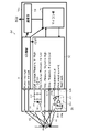
- FIG. 1 is a schematic configuration diagram of a power supply system
- FIG. 2 is a configuration diagram of a battery measuring device
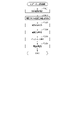
- FIG. 3 is a flowchart of impedance calculation processing
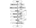
- FIG. 4 is a flowchart of preparation processing
- FIG. 5 is a flowchart of preparation processing of the second embodiment
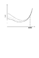
- FIG. 6 is a diagram showing the relationship between complex impedance and frequency
- FIG. 7 is a diagram showing the relationship between the phase of the preparation AC signal and the current value at the start
- FIG. 8 is a diagram showing a preparatory AC signal
- FIG. 9 is a flowchart of preparation processing of the third embodiment
- FIG. 10 is a flow chart of preparation processing of the fourth embodiment.
- a power supply system 10 includes a motor 20 as a rotating electrical machine, an inverter 30 as a power converter that supplies a three-phase current to the motor 20, a rechargeable battery 40, and a rechargeable battery 40. 40, and an ECU 60 for controlling the motor 20 and the like.
- the motor 20 is the vehicle's main engine, and can transmit power to drive wheels (not shown).
- a three-phase permanent magnet synchronous motor is used as the motor 20 .
- the inverter 30 is composed of a full bridge circuit having the same number of upper and lower arms as the number of phases of the phase windings, and by turning on and off the switches (semiconductor switching elements) provided in each arm, current flows in each phase winding. adjusted.
- the inverter 30 is provided with an inverter control device (not shown), and the inverter control device controls energization by turning on and off each switch in the inverter 30 based on various detection information in the motor 20 and requests for power running and power generation. to implement.
- the inverter control device supplies electric power from the assembled battery 40 to the motor 20 via the inverter 30 to drive the motor 20 in power running mode.
- the inverter control device causes the motor 20 to generate power based on the power from the drive wheels, converts the generated power via the inverter 30 and supplies it to the assembled battery 40 to charge the assembled battery 40 .
- the assembled battery 40 is electrically connected to the motor 20 via the inverter 30 .
- the assembled battery 40 has a terminal voltage of, for example, 100 V or more, and is configured by connecting a plurality of battery modules 41 in series.
- the battery module 41 is configured by connecting a plurality of battery cells 42 in series.
- As the battery cell 42 for example, a lithium ion storage battery or a nickel metal hydride storage battery can be used.
- Each battery cell 42 is a storage battery having an electrolyte and a plurality of electrodes.
- a positive terminal of an electrical load such as an inverter 30 is connected to a positive power supply path L1 connected to a positive power supply terminal of the assembled battery 40 .
- a negative terminal of an electrical load such as the inverter 30 is connected to the negative power supply path L2 connected to the negative power supply terminal of the assembled battery 40 .
- a relay switch SMR system main relay switch
- the battery measuring device 50 is a device that measures the state of charge (SOC) and the state of deterioration (SOH) of each battery cell 42 .
- the battery measuring device 50 is connected to the ECU 60 and outputs the state of each battery cell 42 and the like. The configuration of the battery measuring device 50 will be described later.
- the ECU 60 requests the inverter control device for power running and power generation based on various information.
- the various information includes, for example, accelerator and brake operation information, vehicle speed, the state of the assembled battery 40, and the like.
- a battery measuring device 50 is provided for each battery cell 42 .
- the battery measuring device 50 includes an ASIC section 50a, a filter section 55, and a current modulation circuit 56.
- the ASIC unit 50 a includes a stabilized power supply unit 51 , an input/output unit 52 , a microcomputer unit 53 as a calculation unit, and a communication unit 54 .
- the stabilized power supply unit 51 is connected to the power supply line of the battery cell 42 and supplies the power supplied from the battery cell 42 to the input/output unit 52, the microcomputer unit 53, and the communication unit 54.
- the input/output unit 52, the microcomputer unit 53, and the communication unit 54 are driven based on this electric power.
- the input/output unit 52 is connected to the battery cell 42 to be measured. Specifically, the input/output unit 52 has a DC voltage input terminal 57 capable of inputting (measuring) a DC voltage from the battery cell 42 .
- a filter unit 55 is provided between the battery cell 42 and the DC voltage input terminal 57 . That is, between the positive terminal 57a and the negative terminal 57b of the DC voltage input terminal 57, an RC filter 55a as a filter circuit and a Zener diode 55b as a protective element are provided. In other words, the RC filter 55a, the Zener diode 55b, and the like are connected in parallel to the battery cell 42 .
- the input/output unit 52 also has a response signal input terminal 58 for inputting (measuring) a response signal (voltage fluctuation) reflecting the internal complex impedance information of the battery cell 42 between terminals of the battery cell 42 . Therefore, the input/output unit 52 functions as a response signal measuring unit.
- the input/output unit 52 is connected to the current modulation circuit 56, and outputs an instruction signal for instructing the current modulation circuit 56 to output a sine wave signal (AC signal) from the battery cell 42. It has a terminal 59a.
- the input/output unit 52 also has a feedback signal input terminal 59b.
- the feedback signal input terminal 59b inputs a current signal actually output (flowing) from the battery cell 42 via the current modulation circuit 56 as a feedback signal (measurement signal).
- the input/output unit 52 is connected to the microcomputer unit 53, and includes a DC voltage input from the DC voltage input terminal 57, a response signal input from the response signal input terminal 58, and a feedback signal input from the feedback signal input terminal 59b. etc. to the microcomputer unit 53 .
- the input/output unit 52 has an AD converter inside and is configured to convert an input analog signal into a digital signal and output the digital signal to the microcomputer unit 53 .
- the input/output unit 52 is configured to input an instruction signal from the microcomputer unit 53, and is configured to output the instruction signal to the current modulation circuit 56 from the instruction signal output terminal 59a.
- the input/output unit 52 has a DA converter inside, converts a digital signal input from the microcomputer unit 53 into an analog signal, and outputs an instruction signal to the current modulation circuit 56.
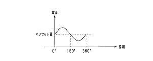
- the sine wave signal instructed by the instruction signal to the current modulation circuit 56 is applied with a DC bias (offset value) so that the sine wave signal does not become a negative current (backflow to the battery cell 42). It's becoming
- the current modulation circuit 56 is a circuit that outputs a predetermined AC signal using the battery cell 42 to be measured as a power source.
- the current modulation circuit 56 has a semiconductor switch element 56a (for example, MOSFET) as a signal control section and a resistor 56b as a shunt resistor connected in series with the semiconductor switch element 56a.
- the drain terminal of the semiconductor switch element 56a is connected to the positive terminal of the battery cell 42, and the source terminal of the semiconductor switch element 56a is connected in series to one end of the resistor 56b.
- the other end of the resistor 56 b is connected to the negative power terminal of the battery cell 42 .
- the semiconductor switch element 56a is configured to be able to adjust the amount of energization between the drain terminal and the source terminal.
- a resistor may be inserted in series in the current modulation circuit in order to adjust the voltage applied to the semiconductor switch element 56a.
- the current modulation circuit 56 is provided with a current measurement amplifier 56c (current sense amplifier) as a current measurement section connected to both ends of the resistor 56b.
- the current measurement amplifier 56c is configured to measure a signal (current signal) flowing through the resistor 56b and output the measurement signal to the feedback signal input terminal 59b of the input/output section 52 as a feedback signal.
- the current modulation circuit 56 is provided with a feedback circuit 56d.
- the feedback circuit 56d is configured to receive the instruction signal from the instruction signal output terminal 59a of the input/output unit 52 and the feedback signal from the current measurement amplifier 56c. Then, the instruction signal and the feedback signal are compared, and the result is output to the gate terminal of the semiconductor switch element 56a.
- the semiconductor switch element 56a Based on the signal from the feedback circuit 56d, the semiconductor switch element 56a applies a voltage between the gate and the source so that the battery cell 42 outputs a sine wave signal (predetermined AC signal) indicated by the instruction signal. Adjust to adjust the amount of current between drain and source. If there is an error between the waveform instructed by the instruction signal and the waveform actually flowing through the resistor 56b, the semiconductor switch element 56a corrects the error based on the signal from the feedback circuit 56d. Adjust the amount of current so that This stabilizes the sinusoidal signal flowing through the resistor 56b.
- the battery measuring device 50 executes the impedance calculation process shown in FIG. 3 at a predetermined cycle.
- the microcomputer unit 53 sets the measurement frequency of the complex impedance (step S101).
- the measurement frequency is set from frequencies within a predetermined measurement range.
- the microcomputer unit 53 determines various parameters of the AC signal (measurement AC signal) to be output from the battery cell 42, and instructs the input/output unit 52 to output the measurement AC signal according to the various parameters.
- An instruction signal is output (step S102).
- the AC signal for measurement is a sine wave signal.
- Various parameters are, for example, the amplitude, frequency, offset value, and phase of the AC signal.
- the microcomputer unit 53 determines the frequency of the sine wave signal (measurement AC signal) based on the measurement frequency.
- the amplitude and offset value of the sine wave signal (measurement AC signal) are predetermined values.
- the input/output unit 52 converts it into an analog signal by the DA converter and outputs it to the current modulation circuit 56 .
- the current modulation circuit 56 uses the battery cell 42 as a power source to output an AC signal for measurement.
- the semiconductor switch element 56a adjusts the amount of current based on the signal input via the feedback circuit 56d so that the measurement AC signal instructed by the instruction signal is output from the battery cell 42. As a result, the measurement AC signal is output from the battery cell 42 .
- the input/output unit 52 receives the voltage fluctuation through a response signal input terminal 58 and outputs it to the microcomputer unit 53 as a response signal. At that time, the signal is converted into a digital signal by an AD converter and output.
- the microcomputer unit 53 After executing step S102, the microcomputer unit 53 inputs a response signal from the input/output unit 52 (step S103). Further, the microcomputer unit 53 acquires a current signal (that is, a measurement AC signal output from the battery cell 42) flowing through the resistor 56b of the current modulation circuit 56 (step S104). Specifically, the microcomputer unit 53 inputs, via the input/output unit 52, a feedback signal (measurement signal) as a current signal output from the current measurement amplifier 56c.
- a current signal that is, a measurement AC signal output from the battery cell 42
- the microcomputer unit 53 inputs, via the input/output unit 52, a feedback signal (measurement signal) as a current signal output from the current measurement amplifier 56c.
- the microcomputer unit 53 calculates information about the complex impedance of the battery cell 42 based on the response signal and the current signal (feedback signal) (step S105). That is, the microcomputer unit 53 calculates all or one of the absolute value and the phase of the complex impedance based on the real part of the response signal, the imaginary part of the response signal, the real part of the current signal, the imaginary part of the current signal, and the like. .
- the microcomputer unit 53 outputs the calculation result to the ECU 60 via the communication unit 54 (step S106). Then, the calculation process ends.
- This impedance calculation process is repeatedly executed until complex impedances are calculated for a plurality of frequencies within the measurement range. For example, the calculation process may be repeatedly executed until the measurement range is swept.
- the ECU 60 creates, for example, a complex impedance plane plot (Cole-Cole plot) based on the calculation results, and grasps the characteristics of the electrodes, the electrolyte, and the like. For example, the state of charge (SOC) and the state of deterioration (SOH) are grasped.
- SOC state of charge
- SOH state of deterioration
- the complex impedance at a specific frequency is measured at regular time intervals, and changes in SOC, SOH, battery temperature, etc. during running may be grasped based on the time change of the complex impedance at the specific frequency.
- the complex impedance at a specific frequency may be measured at time intervals such as every day, every round, or every year, and changes in SOH or the like may be grasped based on the time change in the complex impedance at the specific frequency.
- the feedback signal may not stabilize until a certain period of time elapses after the AC signal starts to be output.
- the resistance temperature of the resistor 56b and the battery temperature rise due to the current flowing through the circuit, and the influence (due to thermal drift) caused thereby.
- the resistance value of the resistor 56b and the internal resistance of the battery cell 42 change as the temperature rises, causing a change in the measurement signal. If the measurement signal is not stable, the calculation accuracy of the complex impedance will decrease.
- the microcomputer unit 53 waits for the measurement signal (feedback signal), which is the measurement result, to reach a steady state, and then calculates information about the complex impedance. and output the calculation results. Specifically, it is explained below.
- the battery measuring device 50 executes the preparation process shown in FIG.
- the microcomputer unit 53 of the battery measuring device 50 sets various parameters for the AC signal (preparation AC signal) to be output from the battery cell 42 (step S201).
- the preparation AC signal is the same as the measurement AC signal (sine wave signal). That is, the microcomputer section 53 may set various parameters of the preparation AC signal in the same manner as in step S102.
- the frequency of the preparatory AC signal is the measurement frequency of the complex impedance.
- the microcomputer section 53 outputs an instruction signal to the input/output section 52 to instruct the output of the preparation AC signal corresponding to the various parameters set in step S201 (step S202).
- the input/output unit 52 converts it into an analog signal by the DA converter and outputs it to the current modulation circuit 56 .
- the current modulation circuit 56 uses the battery cell 42 as a power source to output a preparatory AC signal.
- the microcomputer unit 53 inputs the measurement signal (feedback signal), which is the current signal output from the current measurement amplifier 56c, via the input/output unit 52, and (amplitude difference) is equal to or less than a predetermined change amount (step S203). It should be noted that a negative determination is always made in the first step S203 after the start of the preparation process.
- the microcomputer section 53 executes the process of step S203 again after a predetermined unit time has elapsed. In other words, the process is repeated until the difference in the measurement signals per unit time becomes equal to or less than the specified amount of change. In other words, the preparation process is continued and the impedance calculation process is not executed until the difference in the measurement signals per unit time becomes equal to or less than the specified amount of change.
- step S203 determines that a steady state has been reached, and decides to execute the impedance calculation process (step S204). Then, the preparation process ends. After completing the preparation process, the microcomputer unit 53 executes the impedance calculation process at predetermined intervals as described above.
- the microcomputer 53 waits for the measurement signal (feedback signal), which is the measurement result, to reach a steady state, and then calculates information about the complex impedance. and output the calculation results. Therefore, in the impedance calculation process, it is possible to reduce the temperature rise due to the AC signal for measurement, suppress the error of the measurement signal, and improve the calculation accuracy of the complex impedance.
- the determination is based on the measurement signal that is susceptible to the resistance temperature of the resistor 56b and the battery temperature of the battery cell 42, it is possible to accurately determine whether or not the steady state has been reached. It also has the advantage of not requiring the addition of a special device such as a temperature sensor just for determining the steady state.
- the inspection device is connected to the battery measuring device 50 instead of the battery cell 42 at a factory or the like, and the performance of the battery measuring device 50 is inspected.
- the microcomputer unit 53 by configuring the microcomputer unit 53 to calculate information on the complex impedance after waiting for the feedback signal to reach a steady state, it is possible to reduce errors in the inspection results. becomes.
- the inspection device When the microcomputer unit 53 outputs an instruction signal to cause the inspection device (instead of the battery cell 42) to output an alternating current through the current modulation circuit 56, the inspection device outputs an alternating current corresponding to the instruction signal. At this time, the inspection device measures the outputted alternating current, and the voltage for inspection to be outputted as the result (complex number) of multiplying the predetermined impedance value (impedance value for inspection) and the measured current value. calculate. The inspection device then outputs the calculated inspection voltage to the battery measuring device 50 . The battery measuring device 50 calculates and outputs a complex impedance based on the inspection voltage. The operator or inspection device compares the complex impedance calculated by the battery measurement device 50 and the impedance value for inspection, and inspects the performance of the battery measurement device 50 .
- the inspection device calculates and outputs the voltage for inspection, and includes the steps of inputting the instruction signal ⁇ outputting the alternating current ⁇ measuring the alternating current ⁇ calculating the voltage for inspection ⁇ outputting the voltage for inspection. is required, and a predetermined waiting time is required until the inspection voltage is output. Therefore, when the battery measuring device 50 starts calculating the complex impedance immediately after the start of outputting the preparatory AC signal, the test voltage is not normally output immediately after the start. is likely to occur. Therefore, as described above, after the microcomputer unit 53 causes the current modulation circuit 56 to start outputting the preparatory AC signal, wait for the feedback signal to reach a steady state, and then calculate the information on the complex impedance.
- the predetermined time may be set based on experiments, simulations, or the like. Note that this preparation time may be changed according to the outside air temperature of the vehicle, the resistance temperature of the resistor 56b, and the battery temperature. For example, when the outside air temperature of the vehicle, the resistance temperature of the resistor 56b, or the battery temperature is high, the preparation time may be shortened. Also, the preparation time may be changed based on the elapsed time since the complex impedance was calculated last time. For example, the preparation time may be shortened when the elapsed time from the previous calculation of the complex impedance is short.
- the microcomputer unit 53 outputs the preparatory AC signal, and then calculates the complex impedance based on the response signal (voltage fluctuation) and the measurement signal (current signal) to the preparatory AC signal. It may be determined whether or not the difference (difference from the previous value) in the magnitude (absolute value) of the complex impedance is equal to or less than a predetermined specified amount of change. In other words, it may be determined whether or not the difference in complex impedance per unit time has become equal to or less than a prescribed amount of change. Then, when the result of the determination based on the complex impedance is affirmative, the microcomputer unit 53 may determine that the steady state has been established and decide to execute the impedance calculation process.
- a resistance temperature sensor is provided as a resistance temperature detection unit that detects the resistance temperature of the resistor 56b. or whether the amount of change in resistance temperature (the amount of change from the previous value) has become equal to or less than a predetermined amount of change in resistance temperature. Then, when the determination based on the resistance temperature is affirmative, the microcomputer unit 53 may determine that a steady state has been established and decide to execute the impedance calculation process.
- a battery temperature sensor is provided as a battery temperature detection unit that detects the battery temperature of the battery cell 42, and after outputting an AC signal for preparation, the microcomputer unit 53 detects that the measured battery temperature is It may be determined whether or not a predetermined battery temperature has been reached, or whether or not the amount of change in battery temperature (the amount of change from the previous value) has become equal to or less than a predetermined amount of battery temperature change. Then, when the determination based on the battery temperature is affirmative, the microcomputer unit 53 may determine that the steady state has been reached and decide to execute the impedance calculation process.
- the above-described first embodiment may be implemented in combination with the modification of the above-described first embodiment. For example, if two or more selected from the determination based on the measurement signal (step S203), the determination based on the complex impedance, the determination based on the resistance temperature, and the determination based on the battery temperature are performed, and all of these determination results are positive. , the microcomputer unit 53 may determine that a steady state has been reached.
- the configuration of the first embodiment may be changed as in the following second embodiment.
- the second embodiment differences from the configurations described in the above embodiments will be mainly described.
- the power supply system 10 of the first embodiment will be described as an example of the basic configuration.
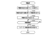
- the battery measuring device 50 sets various parameters for the preparation AC signal to be output from the battery cell 42 during the preparation process (step S301).
- the preparation AC signal is the same as the measurement AC signal (sine wave signal) in step S101. That is, the frequency of the preparation AC signal in the second embodiment is the measurement frequency.
- the microcomputer unit 53 sets a time (hereinafter referred to as preparation time) that is expected to be required from the start of output of the preparation AC signal until a steady state is reached, according to the frequency of the preparation AC signal (step S302).
- preparation time a time (hereinafter referred to as preparation time) that is expected to be required from the start of output of the preparation AC signal until a steady state is reached, according to the frequency of the preparation AC signal (step S302).
- the preparation time corresponding to the frequency of the AC signal for preparation is set based on experiments, simulations, etc., and stored in advance. It should be noted that whether or not the steady state is reached in an experiment or the like is determined comprehensively by using the measurement signal, the calculation result of the complex impedance, the resistance temperature, the battery temperature, or a combination thereof, in the same manner as in the first embodiment and its modification. Judge.
- FIG. 6 shows the relationship between the real part of the complex impedance and the measurement frequency.
- FIG. 6 shows the calculation result of calculating the complex impedance after the preparation time has passed since the output of the AC signal for preparation is started.
- the line type is changed according to the phase difference at the start of the output of the preparation AC signal.
- the measurement frequency is less than a certain frequency (specified frequency)
- the calculation results will vary due to the phase difference at the start of output of the preparation AC signal.
- a certain frequency specified frequency
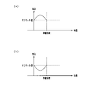
- the ratio of the time period when the current value based on the preparation AC signal is larger than the offset value (current bias) is large until the preparation time elapses, depending on the phase at the start of output. It is considered that this is because there are cases where it becomes smaller (see FIG. 7(b)) and cases where it becomes smaller (see FIG. 7(a)).
- FIG. 7 shows an extreme case.
- the measurement frequency is equal to or higher than the specified frequency, the current value is averaged until the preparation time elapses, and the effect is reduced, so it is considered that no variation occurs.
- the microcomputer unit 53 determines whether or not the frequency of the preparation AC signal is equal to or higher than the specified frequency (step S303). If the determination result in step S303 is negative (if the frequency is less than the specified frequency), the microcomputer unit 53 sets (adjusts) the phase of the AC signal (step S304). Specifically, the microcomputer unit 53 adjusts the current value of the preparatory AC signal at the start of output to be larger than the offset value and the slope of the current based on the preparatory AC signal at the start of output to be positive. , set the phase of the preparatory AC signal at the start of output. That is, when the preparation AC signal is a sine wave signal as shown in FIG. 8, the phase at the start of output is set to zero (0°).
- step S304 the microcomputer unit 53 instructs the input/output unit 52 to use various parameters set in steps S301 and S304.
- An instruction signal for instructing the output of the corresponding preparation AC signal is output (step S305).
- the input/output unit 52 converts it into an analog signal by the DA converter and outputs it to the current modulation circuit 56 .
- the current modulation circuit 56 uses the battery cell 42 as a power source to output a preparatory AC signal.
- step S306 the preparation time set in step S302 elapses.
- step S307 the preparation time set in step S302 has elapsed.
- step S307 the preparation time set in step S307
- the preparation process ends.
- the microcomputer unit 53 executes the impedance calculation process at predetermined intervals as described above.
- the calculation of the complex impedance is started after the preparation time has elapsed. As a result, it is possible to reduce the temperature rise due to the AC signal for measurement, suppress the error of the measurement signal, and improve the calculation accuracy of the complex impedance.
- the microcomputer unit 53 adjusts the current value of the preparatory AC signal at the start of output to be larger than the offset value and the slope of the current based on the preparatory AC signal at the start of output to be positive. , set the phase of the preparatory AC signal at the start of output. For example, when the preparation AC signal is a sine wave signal, the phase at the start of the output is set to zero. As a result, errors in the calculation results can be suppressed, and the standby time can be shortened.
- the preparation time may be set on the assumption that the preparation time will be the longest in consideration of the influence of the phase of the preparation AC signal at the start of output.
- the microcomputer unit 53 assumes that the current value of the AC signal at the start of output is equal to or less than the offset value, and that the slope of the current based on the AC signal at the start of output is negative. should be set.
- the microcomputer unit 53 may set the preparation time on the assumption that the phase of the preparation AC signal at the start of output is 180°. This simplifies the process.
- preparation is performed according to the phase and frequency of the AC signal at the start of input/output.
- the microcomputer unit 53 sets the phase at the start of output to zero (0°), but the phase may be set within the range of 0° or more and less than 90°.
- the configuration of the first embodiment may be changed as in the following third embodiment.
- the third embodiment differences from the configurations described in the above embodiments will be mainly described.
- the power supply system 10 of the first embodiment will be described as an example of the basic configuration.
- step S101 of the impedance calculation process the microcomputer 53 estimates the magnitude of the complex impedance.
- the previously measured complex impedance value for example, Cole-Cole plot
- the microcomputer unit 53 may estimate the magnitude of the complex impedance based on the measurement frequency.
- a complex impedance map is created by experiments, etc., and the complex impedance calculated by referring to the map based on the previously measured deterioration level (SOH), measurement frequency, battery temperature, and other parameters related to the battery state.
- SOH deterioration level
- the magnitude of the impedance may be estimated.
- the microcomputer section 53 functions as an estimation section.
- the microcomputer unit 53 sets the amplitude of the AC signal for measurement according to the magnitude of the estimated complex impedance. Specifically, when the magnitude of the complex impedance is small, it is possible to calculate with higher accuracy by increasing the amplitude. Therefore, when the magnitude of the complex impedance is estimated to be smaller than a predetermined value, the microcomputer unit 53 determines a large amplitude among the amplitudes that can be set. On the other hand, when the magnitude of the complex impedance is large, even if the amplitude is small, it can be calculated with high accuracy. Therefore, when the magnitude of the complex impedance is estimated to be equal to or greater than a predetermined value, the microcomputer 53 determines a small amplitude among the amplitudes that can be set. Note that the amplitude may be set from among settable amplitudes so as to be inversely proportional to the magnitude of the complex impedance.
- the battery measuring device 50 sets various parameters for the AC signal (preparation AC signal) to be output from the battery cell 42 (step S401).
- the preparation AC signal is the same as the measurement AC signal (sine wave signal) in step S101.
- the frequency of the preparation AC signal is the measurement frequency set in the impedance calculation process that is executed first.
- the microcomputer unit 53 sets the preparation time required from the start of signal output to the steady state based on the amplitude of the preparation AC signal (step S402).
- the amplitude of the preparation AC signal is changed according to the amplitude of the measurement AC signal. It is known that the greater the amplitude of the preparatory AC signal, the greater the active power and the more likely the temperature of the resistor 56b and the battery rises. Therefore, the time required from the start of the output of the preparation AC signal to the steady state may be set in proportion to the amplitude of the preparation AC signal.
- a first time period may be set as the preparation time if the amplitude is equal to or greater than a predetermined value, and a second time period that is shorter than the first time may be set if the amplitude is less than the predetermined value. Also, an appropriate preparation time according to the amplitude of the AC signal for preparation may be identified through experiments or the like.
- the microcomputer unit 53 outputs an instruction signal to the input/output unit 52 to instruct the output of the preparation AC signal corresponding to the various parameters set in step S401 (step S403).
- the input/output unit 52 converts it into an analog signal by the DA converter and outputs it to the current modulation circuit 56 .
- the current modulation circuit 56 uses the battery cell 42 as a power source to output a preparatory AC signal.
- step S404 determines whether or not the preparation time set in step S402 has elapsed. If the determination result is negative, the microcomputer unit 53 executes the process of step S404 again after a predetermined period of time has elapsed. In other words, it waits until the preparation time elapses. On the other hand, when the determination result of step S404 is affirmative, the microcomputer unit 53 determines that the steady state has been established, and determines to execute the impedance calculation process (step S405). Then, the preparation process ends. After completing the preparation process, the microcomputer unit 53 executes the impedance calculation process at predetermined intervals as described above.
- the calculation of the complex impedance is started after the preparation time has elapsed.
- the preparation time is changed according to the amplitude of the preparation AC signal. Therefore, an appropriate preparation time can be set.
- the microcomputer unit 53 sets an appropriate amplitude of the AC signal for measurement according to the estimated magnitude of the complex impedance. Therefore, it is possible to improve the calculation accuracy of the complex impedance.
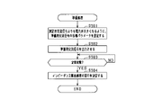
- the battery measuring device 50 sets various parameters for the preparation AC signal to be output from the battery cell 42 (step S501).
- the AC signal for preparation is a signal having a higher power (effective power) than the AC signal for measurement in step S101.
- the microcomputer unit 53 sets the preparation AC signal with an amplitude larger than that of the measurement AC signal. Since the processing after step S502 is the same as the processing after step S202 in the first embodiment, detailed description thereof will be omitted.
- a preparation AC signal with a larger active power than the measurement AC signal is output, and the calculation of the complex impedance is started after the measurement result reaches a steady state.
- the time required to reach a steady state can be shortened.
- step S503 of the fourth embodiment whether or not the steady state has been established may be determined by the same method as in the first embodiment and its modification. That is, one or more determinations selected from the determination based on the measurement signal (step S203), the determination based on the complex impedance, the determination based on the resistance temperature, and the determination based on the battery temperature are performed.
- the microcomputer unit 53 may determine that the steady state has been reached.
- a resistance temperature sensor that measures the resistance temperature of the resistor 56b and a battery temperature sensor that measures the battery temperature of the battery cell 42 are provided, and the magnitude of power is determined according to the resistance temperature and battery temperature.
- Various parameters of the preparation AC signal may be set so as to be changed.
- the microcomputer unit 53 outputs various types of preparation AC signals so that the electric power becomes larger when the resistance temperature or battery temperature at the start of outputting the preparation AC signal is equal to or lower than the threshold value, compared to when it is higher than the threshold value.
- a parameter may be set.
- the microcomputer unit 53 may change various parameters of the preparatory AC signal so as to gradually reduce the power from the start to the steady state. By doing so, it is possible to prevent the temperature (resistance temperature and battery temperature) from rising too much. In addition, it is possible to suppress the influence (induced electromotive force, etc.) due to a rapid change in the current value.
- various parameters of the preparation AC signal may be set so that the power is greater than that of the measurement AC signal. good. This makes it possible to shorten the preparation time.
- the battery measuring device 50 may measure the impedance of the battery cells 42 connected in parallel. That is, in order to increase the battery capacity, a plurality of battery cells 42 may be connected in parallel to form one unit (battery module). Similarly, the battery measuring device 50 may measure the impedance of the battery cells 42 connected in series. In other words, a plurality of battery cells 42 may be connected in series to form one unit (battery module).
- the battery measuring device 50 inputs an AC signal from an external power supply to the battery cell 42 (or battery module 41), measures a response signal (voltage fluctuation) and a current signal to the AC signal, A complex impedance may be calculated based on them.
- the preparation time may be changed for each vehicle type.
- the battery measuring device 50 of the above embodiment may be employed in HEVs, EVs, PHVs, auxiliary batteries, electric airplanes, electric motorcycles, and electric ships as vehicles. Moreover, in the above embodiment, the battery cells 42 may be connected in parallel.
- the AC signal in the above embodiment is a sine wave signal, it may be changed arbitrarily as long as it is an AC signal, and may be a rectangular wave, a triangular wave, or the like.
- the disclosure in this specification is not limited to the illustrated embodiments.
- the disclosure encompasses the illustrated embodiments and variations thereon by those skilled in the art.
- the disclosure is not limited to the combinations of parts and/or elements shown in the embodiments.
- the disclosure can be implemented in various combinations.
- the disclosure can have additional parts that can be added to the embodiments.
- the disclosure encompasses omitting parts and/or elements of the embodiments.
- the disclosure encompasses permutations or combinations of parts and/or elements between one embodiment and another.
- the disclosed technical scope is not limited to the description of the embodiments.
- the disclosed technical scope is indicated by the description of the claims, and should be understood to include all modifications within the meaning and range of equivalents to the description of the claims.
- the controller and techniques described in this disclosure may be implemented by a dedicated computer provided by configuring a processor and memory programmed to perform one or more functions embodied by the computer program.
- the controls and techniques described in this disclosure may be implemented by a dedicated computer provided by configuring the processor with one or more dedicated hardware logic circuits.
- the control units and techniques described in this disclosure can be implemented by a combination of a processor and memory programmed to perform one or more functions and a processor configured by one or more hardware logic circuits. It may also be implemented by one or more dedicated computers configured.
- the computer program may also be stored as computer-executable instructions on a computer-readable non-transitional tangible recording medium.
Landscapes
- General Physics & Mathematics (AREA)
- Physics & Mathematics (AREA)
- Engineering & Computer Science (AREA)
- Chemical Kinetics & Catalysis (AREA)
- Manufacturing & Machinery (AREA)
- Chemical & Material Sciences (AREA)
- Electrochemistry (AREA)
- General Chemical & Material Sciences (AREA)
- Power Engineering (AREA)
- Measurement Of Resistance Or Impedance (AREA)
- Tests Of Electric Status Of Batteries (AREA)
- Charge And Discharge Circuits For Batteries Or The Like (AREA)
- Secondary Cells (AREA)
Priority Applications (3)
| Application Number | Priority Date | Filing Date | Title |
|---|---|---|---|
| DE112022003340.1T DE112022003340T5 (de) | 2021-06-30 | 2022-06-02 | Batteriemessvorrichtung |
| CN202280046927.1A CN117597590A (zh) | 2021-06-30 | 2022-06-02 | 电池测定装置 |
| US18/402,069 US20240230777A9 (en) | 2021-06-30 | 2024-01-02 | Battery measurement device |
Applications Claiming Priority (2)
| Application Number | Priority Date | Filing Date | Title |
|---|---|---|---|
| JP2021109558A JP7619186B2 (ja) | 2021-06-30 | 2021-06-30 | 電池測定装置 |
| JP2021-109558 | 2021-06-30 |
Related Child Applications (1)
| Application Number | Title | Priority Date | Filing Date |
|---|---|---|---|
| US18/402,069 Continuation US20240230777A9 (en) | 2021-06-30 | 2024-01-02 | Battery measurement device |
Publications (1)
| Publication Number | Publication Date |
|---|---|
| WO2023276547A1 true WO2023276547A1 (ja) | 2023-01-05 |
Family
ID=84691325
Family Applications (1)
| Application Number | Title | Priority Date | Filing Date |
|---|---|---|---|
| PCT/JP2022/022533 Ceased WO2023276547A1 (ja) | 2021-06-30 | 2022-06-02 | 電池測定装置 |
Country Status (5)
| Country | Link |
|---|---|
| US (1) | US20240230777A9 (enExample) |
| JP (1) | JP7619186B2 (enExample) |
| CN (1) | CN117597590A (enExample) |
| DE (1) | DE112022003340T5 (enExample) |
| WO (1) | WO2023276547A1 (enExample) |
Families Citing this family (2)
| Publication number | Priority date | Publication date | Assignee | Title |
|---|---|---|---|---|
| KR102899995B1 (ko) * | 2021-09-03 | 2025-12-12 | 주식회사 엘지에너지솔루션 | 전지모듈의 용접 검사 장치 |
| JP7775720B2 (ja) * | 2022-01-20 | 2025-11-26 | 株式会社デンソー | 二次電池システム |
Citations (4)
| Publication number | Priority date | Publication date | Assignee | Title |
|---|---|---|---|---|
| CN102508035A (zh) * | 2011-11-01 | 2012-06-20 | 武汉理工大学 | 一种燃料电池交流阻抗在线测试系统与测控方法 |
| WO2015008728A1 (ja) * | 2013-07-17 | 2015-01-22 | 矢崎総業株式会社 | 電池状態検出装置 |
| JP2015014563A (ja) * | 2013-07-08 | 2015-01-22 | 矢崎総業株式会社 | 電池状態検出装置 |
| WO2017047192A1 (ja) * | 2015-09-18 | 2017-03-23 | 住友電気工業株式会社 | 内部抵抗算出装置、コンピュータプログラム及び内部抵抗算出方法 |
Family Cites Families (2)
| Publication number | Priority date | Publication date | Assignee | Title |
|---|---|---|---|---|
| CN112313521B (zh) | 2018-06-27 | 2023-06-13 | 新唐科技日本株式会社 | 电池监视装置、集成电路以及电池监视系统 |
| JP7256475B2 (ja) | 2020-01-10 | 2023-04-12 | トヨタ自動車株式会社 | 車両走行制御装置 |
-
2021
- 2021-06-30 JP JP2021109558A patent/JP7619186B2/ja active Active
-
2022
- 2022-06-02 WO PCT/JP2022/022533 patent/WO2023276547A1/ja not_active Ceased
- 2022-06-02 CN CN202280046927.1A patent/CN117597590A/zh active Pending
- 2022-06-02 DE DE112022003340.1T patent/DE112022003340T5/de active Pending
-
2024
- 2024-01-02 US US18/402,069 patent/US20240230777A9/en active Pending
Patent Citations (4)
| Publication number | Priority date | Publication date | Assignee | Title |
|---|---|---|---|---|
| CN102508035A (zh) * | 2011-11-01 | 2012-06-20 | 武汉理工大学 | 一种燃料电池交流阻抗在线测试系统与测控方法 |
| JP2015014563A (ja) * | 2013-07-08 | 2015-01-22 | 矢崎総業株式会社 | 電池状態検出装置 |
| WO2015008728A1 (ja) * | 2013-07-17 | 2015-01-22 | 矢崎総業株式会社 | 電池状態検出装置 |
| WO2017047192A1 (ja) * | 2015-09-18 | 2017-03-23 | 住友電気工業株式会社 | 内部抵抗算出装置、コンピュータプログラム及び内部抵抗算出方法 |
Also Published As
| Publication number | Publication date |
|---|---|
| US20240133967A1 (en) | 2024-04-25 |
| CN117597590A (zh) | 2024-02-23 |
| DE112022003340T5 (de) | 2024-04-11 |
| JP7619186B2 (ja) | 2025-01-22 |
| US20240230777A9 (en) | 2024-07-11 |
| JP2023006785A (ja) | 2023-01-18 |
Similar Documents
| Publication | Publication Date | Title |
|---|---|---|
| US11644512B2 (en) | Battery monitoring device | |
| CN113711420B (zh) | 电池监控装置 | |
| CN114566740B (zh) | 动力电池的加热系统和电动车 | |
| US10725108B2 (en) | Battery status estimating device | |
| JP7552776B2 (ja) | 電池監視装置 | |
| CN112242730B (zh) | 电池监视装置 | |
| JP5751207B2 (ja) | 電池直流抵抗評価装置 | |
| US20240133967A1 (en) | Battery measurement device | |
| US20230090001A1 (en) | Battery diagnostic system | |
| WO2015083372A1 (ja) | 電池残存容量推定装置、電池残存容量判定方法及び電池残存容量判定プログラム | |
| US20250020728A1 (en) | Impedance measurement apparatus for secondary battery | |
| US20240133960A1 (en) | Battery measurement method and apparatus | |
| WO2023276577A1 (ja) | 電池測定装置及び電池測定方法 | |
| CN114616478B (zh) | 电池监视装置 | |
| JP2015230169A (ja) | 電池の状態検出装置 | |
| JP2006033970A (ja) | ハイブリッド車のバッテリ管理システム | |
| JP2021162552A (ja) | 蓄電素子の管理装置、蓄電素子の計測方法、及び蓄電装置 | |
| JP2025036486A (ja) | 充電制御装置、充電システム | |
| US20240168100A1 (en) | Battery measurement apparatus and battery state measurement method | |
| JP2018182774A (ja) | 電力変換装置、電力変換方法およびインダクタンス推定装置 | |
| JP2022183938A (ja) | 地絡検出装置 | |
| JP2023154277A (ja) | パワーユニット |
Legal Events
| Date | Code | Title | Description |
|---|---|---|---|
| 121 | Ep: the epo has been informed by wipo that ep was designated in this application |
Ref document number: 22832705 Country of ref document: EP Kind code of ref document: A1 |
|
| WWE | Wipo information: entry into national phase |
Ref document number: 202280046927.1 Country of ref document: CN |
|
| WWE | Wipo information: entry into national phase |
Ref document number: 112022003340 Country of ref document: DE |
|
| 122 | Ep: pct application non-entry in european phase |
Ref document number: 22832705 Country of ref document: EP Kind code of ref document: A1 |