WO2023276115A1 - レーザ加工装置の数値制御装置 - Google Patents
レーザ加工装置の数値制御装置 Download PDFInfo
- Publication number
- WO2023276115A1 WO2023276115A1 PCT/JP2021/024985 JP2021024985W WO2023276115A1 WO 2023276115 A1 WO2023276115 A1 WO 2023276115A1 JP 2021024985 W JP2021024985 W JP 2021024985W WO 2023276115 A1 WO2023276115 A1 WO 2023276115A1
- Authority
- WO
- WIPO (PCT)
- Prior art keywords
- command
- laser
- speed
- laser processing
- period
- Prior art date
- Legal status (The legal status is an assumption and is not a legal conclusion. Google has not performed a legal analysis and makes no representation as to the accuracy of the status listed.)
- Ceased
Links
Images

Classifications
-
- B—PERFORMING OPERATIONS; TRANSPORTING
- B23—MACHINE TOOLS; METAL-WORKING NOT OTHERWISE PROVIDED FOR
- B23K—SOLDERING OR UNSOLDERING; WELDING; CLADDING OR PLATING BY SOLDERING OR WELDING; CUTTING BY APPLYING HEAT LOCALLY, e.g. FLAME CUTTING; WORKING BY LASER BEAM
- B23K26/00—Working by laser beam, e.g. welding, cutting or boring
- B23K26/08—Devices involving relative movement between laser beam and workpiece
- B23K26/083—Devices involving movement of the workpiece in at least one axial direction
-
- B—PERFORMING OPERATIONS; TRANSPORTING
- B23—MACHINE TOOLS; METAL-WORKING NOT OTHERWISE PROVIDED FOR
- B23K—SOLDERING OR UNSOLDERING; WELDING; CLADDING OR PLATING BY SOLDERING OR WELDING; CUTTING BY APPLYING HEAT LOCALLY, e.g. FLAME CUTTING; WORKING BY LASER BEAM
- B23K26/00—Working by laser beam, e.g. welding, cutting or boring
- B23K26/02—Positioning or observing the workpiece, e.g. with respect to the point of impact; Aligning, aiming or focusing the laser beam
- B23K26/06—Shaping the laser beam, e.g. by masks or multi-focusing
- B23K26/062—Shaping the laser beam, e.g. by masks or multi-focusing by direct control of the laser beam
- B23K26/0622—Shaping the laser beam, e.g. by masks or multi-focusing by direct control of the laser beam by shaping pulses
-
- B—PERFORMING OPERATIONS; TRANSPORTING
- B23—MACHINE TOOLS; METAL-WORKING NOT OTHERWISE PROVIDED FOR
- B23K—SOLDERING OR UNSOLDERING; WELDING; CLADDING OR PLATING BY SOLDERING OR WELDING; CUTTING BY APPLYING HEAT LOCALLY, e.g. FLAME CUTTING; WORKING BY LASER BEAM
- B23K26/00—Working by laser beam, e.g. welding, cutting or boring
- B23K26/02—Positioning or observing the workpiece, e.g. with respect to the point of impact; Aligning, aiming or focusing the laser beam
- B23K26/06—Shaping the laser beam, e.g. by masks or multi-focusing
- B23K26/062—Shaping the laser beam, e.g. by masks or multi-focusing by direct control of the laser beam
- B23K26/0626—Energy control of the laser beam
-
- B—PERFORMING OPERATIONS; TRANSPORTING
- B23—MACHINE TOOLS; METAL-WORKING NOT OTHERWISE PROVIDED FOR
- B23K—SOLDERING OR UNSOLDERING; WELDING; CLADDING OR PLATING BY SOLDERING OR WELDING; CUTTING BY APPLYING HEAT LOCALLY, e.g. FLAME CUTTING; WORKING BY LASER BEAM
- B23K26/00—Working by laser beam, e.g. welding, cutting or boring
- B23K26/36—Removing material
Definitions
- the present invention relates to a numerical controller for laser processing equipment.
- Fig. 4(a) shows the moving speed of the workpiece (9) moved by the moving means
- Fig. 4(b) indicates the magnitude of the output from the pulse generator, that is, the magnitude of the frequency
- the magnitude of the output signal from the voltage-frequency converter (15) that is, the magnitude of the frequency. It changes according to the moving speed of the object 9.
- V is the feed speed of the workpiece 9
- F is the frequency of the output waveform of the voltage-frequency converter 15, and
- P the pitch of the actually formed holes (10)
- P the pitch of the pit setter (14) can set the pitch P, and the moving speed V of the workpiece changes. It means that the holes (10) with a constant pitch can be drilled in the workpiece (9). ” is stated.
- pulse lasers are currently being used for various precision processing such as semiconductor product processing and glass lens processing.
- FIG. 3 is a graph showing problems in the conventional technology.
- the horizontal axis indicates the feed speed of the laser processing head.
- the “pulse frequency” graph shows changes in the frequency of the pulsed laser.
- the “pulse period” graph shows changes in the period of the pulsed laser output by the laser processing apparatus.
- the “scan distance per pulse cycle” graph shows the change in the distance traveled by the laser processing head during each cycle of the pulsed laser.
- the distance traveled by the laser processing head during each cycle of the pulse laser may be referred to as "pulse distance interval”.
- the pulse period is the reciprocal of the pulse frequency, if the pulse frequency changes linearly in proportion to the feed speed of the laser processing head, the pulse period should change continuously along a smooth hyperbola.
- the laser processing apparatus is subject to various limitations such as a resolution limit for the pulse period command, and cannot follow the pulse period command calculated based on the pulse frequency.
- the period of the pulsed laser output from the laser processing apparatus changes discontinuously, and steps appear in the graph. The higher the pulse frequency, the more noticeable the step appears in the pulse period graph.
- a numerical control device is a numerical control device that controls a laser processing device that processes the work with a pulse laser emitted from the laser processing head while relatively moving the laser processing head and the work.
- a speed command generation unit that generates a speed command for controlling the speed of the relative movement based on a machining program; and a laser output command value that includes at least the frequency and duty of the pulse laser according to the speed command.
- a laser command generation unit that calculates a cycle command of the pulse laser based on the frequency, and calculates a rate of change of the post-change cycle command with respect to the cycle command due to performance limitations of the laser processing apparatus.
- a change rate calculation unit and a speed adjustment unit that adjusts the speed command generated by the speed command generation unit using the change rate.
- the intervals between the spots irradiated onto the processing surface by the pulse laser can be made constant.
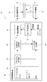
- FIG. 1 is a block diagram showing the configuration of a numerical controller in one embodiment of the present invention.
- FIG. It is a schematic diagram explaining the effect of one Embodiment of this invention. It is a graph explaining the problem in a prior art.
- FIG. 1 is a block diagram showing the configuration of a numerical controller according to one embodiment of the present invention.
- the numerical control device of this embodiment is a numerical control device 20 that controls a laser processing device 10 that processes a workpiece with a pulsed laser emitted from a laser processing head 14 .
- the laser processing apparatus 10 has a laser control unit 11 that controls a pulse laser emitted from a laser processing head 14, and a drive shaft control unit 12 that controls a drive shaft 13 that relatively moves the laser processing head 14 and a work.
- the workpiece is fixed and only the laser processing head 14 is moved by the drive shaft 13 controlled by the drive shaft controller 12 . That is, the feed speed (moving speed) of the laser processing head 14 is the relative moving speed between the laser processing head 14 and the work.
- the numerical controller 20 includes a program analysis section 22, a speed command generation section 23, a laser command generation section 24, a change rate calculation section 25, and a speed adjustment section 26.
- the program analysis unit 22 analyzes the machining program 21 and sends the analyzed information to related parts. For example, information about the feed speed of the laser processing head 14 is sent to the speed command generator 23 , and information about the frequency of the pulse laser is sent to the laser command generator 24 .
- the speed command generation unit 23 generates a speed command F for controlling the feed speed of the laser processing head 14 based on the processing program 21 analyzed by the program analysis unit 22 .
- the speed command generator 23 sends the generated speed command F to the laser command generator 24 and the speed adjuster 26 .
- the laser command generator 24 can control the power of the pulse laser.
- the laser command generator 24 generates a laser output command value including at least the frequency and duty of the pulse laser according to the speed command F.
- the laser command generation unit 24 generates a pulsed laser frequency command value f proportional to the speed command F according to the following formula 1, and sends it to the change rate calculation unit 25 and the laser control unit 11 .
- D is a constant, which is the distance that the laser processing head 14 travels during each cycle of the pulsed laser, which the laser processing apparatus 10 aims for.
- the constant D is also referred to as "target pulse distance interval".
- the rate-of-change calculator 25 calculates the rate of change R of the post-change period command T′ that has changed due to the performance limitations of the laser processing apparatus 10 with respect to the period command T, and sends it to the speed adjustment unit 26 .
- the periodic change rate R is calculated by Equation 2 below.
- n is an arbitrary natural number.
- T(n) is the period immediately before the change in the period command (the deviation from the period command (1/f) calculated based on the frequency command value f) begins due to the limitation of the performance of the laser processing apparatus 10. Directive.
- T'(n+a) is the post-change cycle command T' at each point in time while the cycle command is changing.
- a is a natural number such as "1, 2, 3, ". If the rate of change (acceleration) of the velocity command F with respect to time changes, T(n) at the new acceleration should be used.
- the speed adjustment unit 26 uses the periodic change rate R to adjust the speed command F generated by the speed command generation unit 23 , generates an adjusted speed command F′, and sends it to the drive shaft control unit 12 .
- the speed adjustment unit 26 adjusts the speed command based on Equation 3 below.
- F(n) is the speed command F at time n corresponding to T(n).
- the post-change period command T' is calculated by simulated calculation by the rate-of-change calculator 25 based on a model that reflects the performance limits of the laser processing apparatus 10 with respect to the period command T.
- the change rate calculator 25 calculates the post-change cycle command T′ based on a model that reflects the limitation of the resolution of the laser processing apparatus 10 with respect to the cycle command T.
- the limitation of the resolution of the laser processing apparatus 10 and the calculation method of the post-change period command T' reflecting the limitation will be described below.
- the resolution S with respect to the cycle command T of the laser processing apparatus 10 is 0.5 ⁇ s
- the cycle command T(n) of the pulse laser at time n calculated by the change rate calculator 25 based on the frequency command value f is 0.5 ⁇ s.
- the period command T(n+1) at the point (n+1) is 0.6 ⁇ s
- the period command T(n+2) at the point (n+2) is 0.7 ⁇ s
- the period command T(n+3) at the point (n+3) ) is 0.8 ⁇ s
- the period command T(n+4) at the point (n+4) is 0.9 ⁇ s
- the period command T(n+5) at the point (n+5) is 1.0 ⁇ s
- the period at the point (n+6) Assume that command T(n+6) is 1.1 ⁇ s. It is assumed that the rate of change (acceleration) of the speed command F with respect to time is constant. The same applies to the period command T calculated by the laser control unit 11 based on the frequency command value f.
- the laser processing apparatus 10 can follow changes in the periodic command, and can control the pulse laser according to the periodic command.
- the laser processing apparatus 10 responds to changes in the periodic command cannot follow.
- the laser processing apparatus 10 controls the pulse laser with the period command (0.5 ⁇ s) at the n time that is an integer multiple of the resolution S before that, and (n+6 ), the pulse laser is controlled by the periodic command (1.0 ⁇ s) at the time (n+5), which is an integral multiple of the resolution S before that.
- the cycle command that actually controls the pulse laser changes step by step as shown in the "pulse cycle" graph in FIG.
- the pulse distance interval cannot be made constant like the target pulse distance interval D.
- the present embodiment calculates a post-change period command T' that approximates the period command for actually controlling the pulse laser, reflecting the limitation of the resolution of the laser processing apparatus 10.
- floor is a function used in C language, etc., and is a function for rounding off the decimal point of a numerical value.
- S is the resolution of the laser processing apparatus 10 with respect to the periodic command T
- T is the periodic command calculated based on the frequency command value f.
- the post-change cycle command T′ is the following Equation 5: becomes 0.5 ⁇ s as shown in .
- the post-change period command T' at points (n+1) to (n+4) are all 0.5 ⁇ s, and ( The post-change period command T' at time points n+5) and (n+6) is 1.0 ⁇ s.
- the laser processing apparatus 10 controls the pulse laser using the periodic command at the time when it becomes an integer multiple of the resolution S before that. are the same. That is, the model expressed by Equation 4 can reflect the influence of the limitation on the resolution of the laser processing apparatus 10 on the periodic command.
- the change rate calculator 25 calculates the post-change cycle command T' by Equation 4, calculates the cycle change rate R by Equation 2, and sends it to the speed adjuster 26.
- the speed adjustment unit 26 uses the periodic change rate R to adjust the speed command F according to Equation 3 to generate the adjusted speed command F'.
- the drive shaft controller 12 controls the feed speed of the laser processing head 14 based on the post-adjustment speed command F'.
- (n+1) to (n+6) correspond to "(n+a)” in Equation 2, and at these points the cycle command is changed and deviates from the calculated cycle command (1/f), and the post-change cycle It becomes the command T'(n+a).
- the post-change cycle command T'(n+5) is equal to the cycle command T(n+5) and is 1.0 ⁇ s.
- the periodic command for actually controlling the pulse laser matches the periodic command (1/f) calculated based on the frequency command value f, and the calculated periodic command (1/f ).
- Equation 4 is used to calculate the cycle after change at such a time. Even if the command T' is calculated, a result that correctly reflects the situation can be obtained. Therefore, in the present embodiment, the period command that exists while the period command is changing and matches the calculated period command (1/f) is also treated as the post-change period command T'. do.
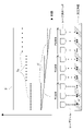
- FIG. 2 is a schematic diagram explaining the effect of this embodiment.
- the upper part of FIG. 2 is a schematic diagram showing changes in each parameter over time.
- the lower part of FIG. 2 is a schematic diagram showing the distance traveled by the laser processing head in each cycle of the pulse laser under each adjusted speed command F', that is, the adjusted pulse distance interval D'.
- FIG. 2 shows an example in which the speed command F for controlling the feed speed of the laser processing head is linearly decreased.
- the measured value Ta of the pulsed laser period is discontinuous with respect to time, and a step appears.
- the change in the post-adjustment speed command F' calculated by Equations 2 and 3 using the post-change cycle command T' also shows a step corresponding to the cycle actual measurement value Ta.
- the adjusted pulse distance interval D' remains constant even if the feed speed changes. value. That is, the distance traveled by the laser processing head during each cycle of the pulse laser is controlled to be constant.
- Equation 6 For example, in FIG. 2, if the value of the point sequence on the left side of the period measured value Ta is 0.5 ⁇ s, the value of the point sequence in the center is 1.0 ⁇ s, and the value of the point sequence on the right is 1.5 ⁇ s. do. As indicated by "F60000”, “F30000” and “F20000", the value of the point sequence on the left side of the post-adjustment speed command F' is 60000 mm/min, and the value of the point sequence in the center is 30000 mm/min. and the value of the point sequence on the right is 20000 mm/min.
- FIG. 2 The lower part of FIG. 2 is a schematic diagram imagining that the distance traveled by the laser processing head during each cycle of the pulse laser can be controlled to be constant even under different feed speeds.
- the interval between the dot sequences indicating the period actual measurement value Ta and the interval between the dot sequences representing the laser beam represent the size of each period of the corresponding pulse laser.
- the numerical control device calculates the post-change cycle command T' by simulation calculation of the change rate calculation unit 25 based on a model that reflects the performance limit of the laser processing device 10 with respect to the cycle command T, and the cycle
- the cyclic change rate R of the post-change cyclic command T' with respect to the command T and adjusting the speed command F using the cyclic change rate R even under different feed rates, during each cycle of the pulsed laser
- the distance traveled by the laser processing head 14 can be controlled to be constant, and the interval between spots irradiated on the processing surface by the pulse laser can be controlled to be constant.
- This embodiment is a modification of the first embodiment.
- the laser processing apparatus and its numerical control apparatus according to this embodiment can have the configurations of the laser processing apparatus 10 and the numerical control apparatus 20 shown in FIG. Therefore, descriptions of components having the same functions as those of the first embodiment will be omitted.
- the main difference between the present embodiment and the first embodiment is that, as the post-change period command T′ used in Equation 2 for calculating the period change rate R, the measured period value Ta of the pulse laser actually measured in the test run of the laser processing apparatus 10 is used. It is to use. That is, the change rate calculation unit 25 does not calculate the post-change cycle command T' based on the model, but calculates the cycle change rate R using the stored cycle actual measurement value Ta, and sends it to the speed adjustment unit 26. send. The speed adjustment unit 26 adjusts the speed command based on Equation 3 using the periodic change rate. If there is a measurement error or the like in the cyclic actual value Ta, processing may be performed to reduce the measurement error or the like, and the cyclic change rate R may be calculated using a value calculated based on the cyclic actual value Ta.
- the period actual measurement value Ta is a value subject to various performance limitations of the laser processing apparatus 10
- the speed command F is adjusted by the period change rate R calculated using the measured value Ta
- the post-adjustment pulse distance interval D' can be obtained more accurately. can be controlled to be constant.
- Each component of the numerical controller 20 may consist of a program that describes its operation and a CPU that executes the program.
- the numerical control device 20 may be configured by a computer, and the CPU of the computer may implement each configuration by executing a program describing the function of each configuration of the numerical control device 20 .
- the change rate calculator 25 and the laser controller 11 each calculate the cycle command T based on the frequency command value f. Alternatively, it may be sent to the unit 25 and the laser control unit 11 .
Landscapes
- Physics & Mathematics (AREA)
- Optics & Photonics (AREA)
- Engineering & Computer Science (AREA)
- Plasma & Fusion (AREA)
- Mechanical Engineering (AREA)
- Laser Beam Processing (AREA)
- Numerical Control (AREA)
Abstract
Description
F=V/P’と表せ、
これからピッチはP’=V/F ……(1)となる。
また、実際に形成される穴(10)のピッチをPとすると、
P=V/Fという関係があり、上記(1)式よりP=P’となり、ピット設定器(14)の出力はピッチPを設定することができ、被加工物の移動速度Vが変化しても一定のピッチの穴(10)を被加工物(9)に開けることができることになる。」と記載されている。
上述した穴開けのほか、現在、半導体製品の加工、ガラスレンズの加工など、様々な精密加工にもパルスレーザを活用している。
図1は、本発明の一実施形態における数値制御装置の構成を示すブロック図である。この実施形態の数値制御装置は、レーザ加工ヘッド14から出射するパルスレーザによってワークを加工するレーザ加工装置10を制御する数値制御装置20である。当該レーザ加工装置10は、レーザ加工ヘッド14から出射するパルスレーザを制御するレーザ制御部11と、レーザ加工ヘッド14とワークを相対移動させる駆動軸13を制御する駆動軸制御部12を有する。本実施形態の説明を簡潔にするために、本実施形態において、ワークが固定され、駆動軸制御部12が制御する駆動軸13がレーザ加工ヘッド14だけを移動させることとする。すなわち、レーザ加工ヘッド14の送り速度(移動速度)がレーザ加工ヘッド14とワークの相対移動速度である。






本実施形態は、実施形態1の変形である。本実施形態に係るレーザ加工装置及びその数値制御装置は、図1に示したレーザ加工装置10及び数値制御装置20の構成を有することができる。よって、実施形態1と同じ機能を有する構成要素について、その説明を省略する。
11 レーザ制御部
12 駆動軸制御部
13 駆動軸
14 レーザ加工ヘッド
20 数値制御装置
21 加工プログラム
22 プログラム解析部
23 速度指令生成部
24 レーザ指令生成部
25 変化率演算部
26 速度調整部
D 目標パルス距離間隔
D’ 調整後パルス距離間隔
f 周波数指令値
F 速度指令
F’ 調整後速度指令
R 周期変化率
S 周期指令の分解能
T 周期指令
T’ 変化後周期指令
Ta 周期実測値
Claims (4)
- レーザ加工ヘッドとワークを相対移動させながら、前記レーザ加工ヘッドから出射するパルスレーザによって前記ワークを加工するレーザ加工装置を制御する数値制御装置であって、
加工プログラムに基づいて、前記相対移動の速度を制御する速度指令を生成する速度指令生成部と、
前記速度指令に応じて、少なくとも前記パルスレーザの周波数、デューティを含むレーザ出力指令値を生成するレーザ指令生成部と、
前記周波数に基づいて前記パルスレーザの周期指令を算出し、前記周期指令に対して、前記レーザ加工装置の性能の制限によって変化した変化後周期指令の変化率を計算する変化率演算部と、
前記変化率を用いて、前記速度指令生成部が生成した前記速度指令を調整する速度調整部と、を備える
数値制御装置。 - 請求項1に記載の数値制御装置であって、
前記変化後周期指令は、前記周期指令に対する前記レーザ加工装置の性能の制限を反映させるモデルに基づいて、前記変化率演算部の模擬計算によって算出される。 - 請求項2に記載の数値制御装置であって、
前記レーザ加工装置の性能の制限は、前記周期指令に対する前記レーザ加工装置の分解能の制限である。 - 請求項1に記載の数値制御装置であって、
前記変化後周期指令として、前記レーザ加工装置の試運転において実測された前記パルスレーザの周期実測値を用いる、又は前記周期実測値に基づいて算出された値を用いる。
Priority Applications (5)
| Application Number | Priority Date | Filing Date | Title |
|---|---|---|---|
| DE112021007548.9T DE112021007548T5 (de) | 2021-07-01 | 2021-07-01 | Laserbearbeitungsvorrichtung und numerische Steuervorrichtung |
| CN202180099841.0A CN117580671A (zh) | 2021-07-01 | 2021-07-01 | 激光加工装置的数值控制装置 |
| US18/571,099 US20240278351A1 (en) | 2021-07-01 | 2021-07-01 | Laser machining device and numerical control device |
| JP2023531297A JP7557069B2 (ja) | 2021-07-01 | 2021-07-01 | レーザ加工装置の数値制御装置 |
| PCT/JP2021/024985 WO2023276115A1 (ja) | 2021-07-01 | 2021-07-01 | レーザ加工装置の数値制御装置 |
Applications Claiming Priority (1)
| Application Number | Priority Date | Filing Date | Title |
|---|---|---|---|
| PCT/JP2021/024985 WO2023276115A1 (ja) | 2021-07-01 | 2021-07-01 | レーザ加工装置の数値制御装置 |
Publications (1)
| Publication Number | Publication Date |
|---|---|
| WO2023276115A1 true WO2023276115A1 (ja) | 2023-01-05 |
Family
ID=84692577
Family Applications (1)
| Application Number | Title | Priority Date | Filing Date |
|---|---|---|---|
| PCT/JP2021/024985 Ceased WO2023276115A1 (ja) | 2021-07-01 | 2021-07-01 | レーザ加工装置の数値制御装置 |
Country Status (5)
| Country | Link |
|---|---|
| US (1) | US20240278351A1 (ja) |
| JP (1) | JP7557069B2 (ja) |
| CN (1) | CN117580671A (ja) |
| DE (1) | DE112021007548T5 (ja) |
| WO (1) | WO2023276115A1 (ja) |
Citations (3)
| Publication number | Priority date | Publication date | Assignee | Title |
|---|---|---|---|---|
| JPS58212886A (ja) * | 1982-06-03 | 1983-12-10 | Fuji Electric Co Ltd | レ−ザ刻印装置 |
| JPS5942194A (ja) * | 1982-09-01 | 1984-03-08 | Mitsubishi Electric Corp | レ−ザ穴開け装置 |
| JP2010271433A (ja) * | 2009-05-20 | 2010-12-02 | Funai Electric Co Ltd | レーザプロジェクタ |
Family Cites Families (3)
| Publication number | Priority date | Publication date | Assignee | Title |
|---|---|---|---|---|
| KR20150092600A (ko) * | 2014-02-05 | 2015-08-13 | 에이피시스템 주식회사 | 레이저 처리 장치 및 레이저 처리 방법 |
| CN104979748B (zh) * | 2015-06-26 | 2018-04-27 | 吉林大学 | 飞秒激光扫描功率调控装置和方法、飞秒激光加工系统 |
| JP2018030162A (ja) * | 2016-08-26 | 2018-03-01 | ファナック株式会社 | レーザ制御装置 |
-
2021
- 2021-07-01 WO PCT/JP2021/024985 patent/WO2023276115A1/ja not_active Ceased
- 2021-07-01 CN CN202180099841.0A patent/CN117580671A/zh active Pending
- 2021-07-01 US US18/571,099 patent/US20240278351A1/en active Pending
- 2021-07-01 JP JP2023531297A patent/JP7557069B2/ja active Active
- 2021-07-01 DE DE112021007548.9T patent/DE112021007548T5/de active Pending
Patent Citations (3)
| Publication number | Priority date | Publication date | Assignee | Title |
|---|---|---|---|---|
| JPS58212886A (ja) * | 1982-06-03 | 1983-12-10 | Fuji Electric Co Ltd | レ−ザ刻印装置 |
| JPS5942194A (ja) * | 1982-09-01 | 1984-03-08 | Mitsubishi Electric Corp | レ−ザ穴開け装置 |
| JP2010271433A (ja) * | 2009-05-20 | 2010-12-02 | Funai Electric Co Ltd | レーザプロジェクタ |
Also Published As
| Publication number | Publication date |
|---|---|
| JPWO2023276115A1 (ja) | 2023-01-05 |
| JP7557069B2 (ja) | 2024-09-26 |
| CN117580671A (zh) | 2024-02-20 |
| DE112021007548T5 (de) | 2024-02-22 |
| US20240278351A1 (en) | 2024-08-22 |
Similar Documents
| Publication | Publication Date | Title |
|---|---|---|
| US10744599B2 (en) | Metal additive manufacturing welding condition control device and method | |
| CN112276365B (zh) | 一种金属增材构件大幅面激光抛光加工方法 | |
| JP4973982B2 (ja) | ガルバノスキャナシステムおよび制御方法 | |
| KR101511483B1 (ko) | 가공 제어 장치, 레이저 가공 장치 및 가공 제어 방법 | |
| JP5576211B2 (ja) | レーザ加工装置及びレーザ加工方法 | |
| CN114746206A (zh) | 坐标图案文件制作装置、轨迹图案制作装置及激光加工机的控制方法 | |
| CN110545949A (zh) | 三维激光加工机及三维激光加工机的控制方法 | |
| US11249460B2 (en) | Numerical control device and method for controlling additive manufacturing apparatus | |
| JP7557069B2 (ja) | レーザ加工装置の数値制御装置 | |
| CN117359092A (zh) | 一种激光加工方法及装置 | |
| JP6167307B2 (ja) | レーザ加工装置 | |
| JP5162471B2 (ja) | 軸方向での相対位置及び/又は相対運動を制御するための方法、並びに、工作機械 | |
| US12326713B2 (en) | Servo control device | |
| JP5255905B2 (ja) | 微細形状切削加工方法および微細形状切削加工装置 | |
| WO2020008779A1 (ja) | 切削加工機及び切削加工方法 | |
| JP5943627B2 (ja) | レーザ加工装置及びレーザ加工方法 | |
| CN116829294B (zh) | 时间差设定装置以及数值控制装置 | |
| US20260102847A1 (en) | Control method for laser processing machine | |
| TWI896306B (zh) | 高效率雷射直線槽的加工方法和加工裝置 | |
| JP4334010B2 (ja) | エネルギー測定方法及びエネルギー測定装置 | |
| JP2004230441A (ja) | 加工機の制御方法及び装置 | |
| JP5383026B2 (ja) | 加工速度を調整するレーザ加工装置及びレーザ加工方法 | |
| US20260079454A1 (en) | Control parameter adjustment device and control parameter adjustment method | |
| RU2777735C2 (ru) | Устройство для трехмерного формирования заготовки | |
| TW202302258A (zh) | 為不同雷射器類型確定雷射控制信號之方法及雷射繪圖機以及用於此的振鏡打標雷射器 |
Legal Events
| Date | Code | Title | Description |
|---|---|---|---|
| 121 | Ep: the epo has been informed by wipo that ep was designated in this application |
Ref document number: 21948419 Country of ref document: EP Kind code of ref document: A1 |
|
| WWE | Wipo information: entry into national phase |
Ref document number: 2023531297 Country of ref document: JP |
|
| WWE | Wipo information: entry into national phase |
Ref document number: 112021007548 Country of ref document: DE |
|
| WWE | Wipo information: entry into national phase |
Ref document number: 18571099 Country of ref document: US |
|
| WWE | Wipo information: entry into national phase |
Ref document number: 202180099841.0 Country of ref document: CN |
|
| 122 | Ep: pct application non-entry in european phase |
Ref document number: 21948419 Country of ref document: EP Kind code of ref document: A1 |