WO2023276018A1 - Laser radar device - Google Patents
Laser radar device Download PDFInfo
- Publication number
- WO2023276018A1 WO2023276018A1 PCT/JP2021/024659 JP2021024659W WO2023276018A1 WO 2023276018 A1 WO2023276018 A1 WO 2023276018A1 JP 2021024659 W JP2021024659 W JP 2021024659W WO 2023276018 A1 WO2023276018 A1 WO 2023276018A1
- Authority
- WO
- WIPO (PCT)
- Prior art keywords
- intensity
- signal
- pulse
- modulated
- received
- Prior art date
Links
- 238000012545 processing Methods 0.000 claims abstract description 77
- 230000003287 optical effect Effects 0.000 claims description 125
- 238000012546 transfer Methods 0.000 claims description 74
- 230000005540 biological transmission Effects 0.000 claims description 48
- 238000004364 calculation method Methods 0.000 claims description 42
- 230000000704 physical effect Effects 0.000 claims description 40
- 238000012937 correction Methods 0.000 claims description 25
- 238000001228 spectrum Methods 0.000 claims description 20
- 238000010521 absorption reaction Methods 0.000 claims description 7
- 230000010287 polarization Effects 0.000 claims description 5
- 230000003595 spectral effect Effects 0.000 claims description 3
- 230000004044 response Effects 0.000 claims description 2
- 230000006870 function Effects 0.000 description 77
- 238000000034 method Methods 0.000 description 28
- 238000010586 diagram Methods 0.000 description 23
- 230000010354 integration Effects 0.000 description 20
- 230000008033 biological extinction Effects 0.000 description 17
- 238000006243 chemical reaction Methods 0.000 description 14
- 230000007274 generation of a signal involved in cell-cell signaling Effects 0.000 description 14
- 238000004458 analytical method Methods 0.000 description 10
- 238000005259 measurement Methods 0.000 description 6
- 230000008569 process Effects 0.000 description 6
- 230000000875 corresponding effect Effects 0.000 description 5
- 230000009471 action Effects 0.000 description 4
- 230000000694 effects Effects 0.000 description 3
- 238000001914 filtration Methods 0.000 description 3
- 238000012986 modification Methods 0.000 description 3
- 230000004048 modification Effects 0.000 description 3
- 239000002245 particle Substances 0.000 description 3
- 101000661807 Homo sapiens Suppressor of tumorigenicity 14 protein Proteins 0.000 description 2
- 230000008859 change Effects 0.000 description 2
- 230000001427 coherent effect Effects 0.000 description 2
- 239000013078 crystal Substances 0.000 description 2
- 238000001514 detection method Methods 0.000 description 2
- 238000005516 engineering process Methods 0.000 description 2
- 230000000644 propagated effect Effects 0.000 description 2
- 239000004065 semiconductor Substances 0.000 description 2
- 239000002131 composite material Substances 0.000 description 1
- 230000001276 controlling effect Effects 0.000 description 1
- 238000007796 conventional method Methods 0.000 description 1
- 230000002596 correlated effect Effects 0.000 description 1
- 230000003111 delayed effect Effects 0.000 description 1
- 238000013461 design Methods 0.000 description 1
- 230000009977 dual effect Effects 0.000 description 1
- 239000000835 fiber Substances 0.000 description 1
- 238000007429 general method Methods 0.000 description 1
- 230000001678 irradiating effect Effects 0.000 description 1
- 238000004519 manufacturing process Methods 0.000 description 1
- 238000010606 normalization Methods 0.000 description 1
- 239000013307 optical fiber Substances 0.000 description 1
- 238000003672 processing method Methods 0.000 description 1
- 238000000926 separation method Methods 0.000 description 1
- 238000007493 shaping process Methods 0.000 description 1
- 238000004088 simulation Methods 0.000 description 1
- 239000007787 solid Substances 0.000 description 1
Images


Classifications
-
- G—PHYSICS
- G01—MEASURING; TESTING
- G01S—RADIO DIRECTION-FINDING; RADIO NAVIGATION; DETERMINING DISTANCE OR VELOCITY BY USE OF RADIO WAVES; LOCATING OR PRESENCE-DETECTING BY USE OF THE REFLECTION OR RERADIATION OF RADIO WAVES; ANALOGOUS ARRANGEMENTS USING OTHER WAVES
- G01S13/00—Systems using the reflection or reradiation of radio waves, e.g. radar systems; Analogous systems using reflection or reradiation of waves whose nature or wavelength is irrelevant or unspecified
- G01S13/02—Systems using reflection of radio waves, e.g. primary radar systems; Analogous systems
- G01S13/06—Systems determining position data of a target
- G01S13/08—Systems for measuring distance only
- G01S13/10—Systems for measuring distance only using transmission of interrupted, pulse modulated waves
- G01S13/103—Systems for measuring distance only using transmission of interrupted, pulse modulated waves particularities of the measurement of the distance
-
- G—PHYSICS
- G01—MEASURING; TESTING
- G01N—INVESTIGATING OR ANALYSING MATERIALS BY DETERMINING THEIR CHEMICAL OR PHYSICAL PROPERTIES
- G01N21/00—Investigating or analysing materials by the use of optical means, i.e. using sub-millimetre waves, infrared, visible or ultraviolet light
- G01N21/17—Systems in which incident light is modified in accordance with the properties of the material investigated
- G01N21/47—Scattering, i.e. diffuse reflection
- G01N21/49—Scattering, i.e. diffuse reflection within a body or fluid
-
- G—PHYSICS
- G01—MEASURING; TESTING
- G01S—RADIO DIRECTION-FINDING; RADIO NAVIGATION; DETERMINING DISTANCE OR VELOCITY BY USE OF RADIO WAVES; LOCATING OR PRESENCE-DETECTING BY USE OF THE REFLECTION OR RERADIATION OF RADIO WAVES; ANALOGOUS ARRANGEMENTS USING OTHER WAVES
- G01S17/00—Systems using the reflection or reradiation of electromagnetic waves other than radio waves, e.g. lidar systems
- G01S17/02—Systems using the reflection of electromagnetic waves other than radio waves
- G01S17/06—Systems determining position data of a target
- G01S17/08—Systems determining position data of a target for measuring distance only
- G01S17/10—Systems determining position data of a target for measuring distance only using transmission of interrupted, pulse-modulated waves
-
- G—PHYSICS
- G01—MEASURING; TESTING
- G01S—RADIO DIRECTION-FINDING; RADIO NAVIGATION; DETERMINING DISTANCE OR VELOCITY BY USE OF RADIO WAVES; LOCATING OR PRESENCE-DETECTING BY USE OF THE REFLECTION OR RERADIATION OF RADIO WAVES; ANALOGOUS ARRANGEMENTS USING OTHER WAVES
- G01S17/00—Systems using the reflection or reradiation of electromagnetic waves other than radio waves, e.g. lidar systems
- G01S17/88—Lidar systems specially adapted for specific applications
- G01S17/95—Lidar systems specially adapted for specific applications for meteorological use
-
- G—PHYSICS
- G01—MEASURING; TESTING
- G01S—RADIO DIRECTION-FINDING; RADIO NAVIGATION; DETERMINING DISTANCE OR VELOCITY BY USE OF RADIO WAVES; LOCATING OR PRESENCE-DETECTING BY USE OF THE REFLECTION OR RERADIATION OF RADIO WAVES; ANALOGOUS ARRANGEMENTS USING OTHER WAVES
- G01S7/00—Details of systems according to groups G01S13/00, G01S15/00, G01S17/00
- G01S7/02—Details of systems according to groups G01S13/00, G01S15/00, G01S17/00 of systems according to group G01S13/00
- G01S7/024—Details of systems according to groups G01S13/00, G01S15/00, G01S17/00 of systems according to group G01S13/00 using polarisation effects
-
- G—PHYSICS
- G01—MEASURING; TESTING
- G01S—RADIO DIRECTION-FINDING; RADIO NAVIGATION; DETERMINING DISTANCE OR VELOCITY BY USE OF RADIO WAVES; LOCATING OR PRESENCE-DETECTING BY USE OF THE REFLECTION OR RERADIATION OF RADIO WAVES; ANALOGOUS ARRANGEMENTS USING OTHER WAVES
- G01S7/00—Details of systems according to groups G01S13/00, G01S15/00, G01S17/00
- G01S7/02—Details of systems according to groups G01S13/00, G01S15/00, G01S17/00 of systems according to group G01S13/00
- G01S7/40—Means for monitoring or calibrating
- G01S7/4004—Means for monitoring or calibrating of parts of a radar system
- G01S7/4008—Means for monitoring or calibrating of parts of a radar system of transmitters
- G01S7/4013—Means for monitoring or calibrating of parts of a radar system of transmitters involving adjustment of the transmitted power
-
- Y—GENERAL TAGGING OF NEW TECHNOLOGICAL DEVELOPMENTS; GENERAL TAGGING OF CROSS-SECTIONAL TECHNOLOGIES SPANNING OVER SEVERAL SECTIONS OF THE IPC; TECHNICAL SUBJECTS COVERED BY FORMER USPC CROSS-REFERENCE ART COLLECTIONS [XRACs] AND DIGESTS
- Y02—TECHNOLOGIES OR APPLICATIONS FOR MITIGATION OR ADAPTATION AGAINST CLIMATE CHANGE
- Y02A—TECHNOLOGIES FOR ADAPTATION TO CLIMATE CHANGE
- Y02A90/00—Technologies having an indirect contribution to adaptation to climate change
- Y02A90/10—Information and communication technologies [ICT] supporting adaptation to climate change, e.g. for weather forecasting or climate simulation
Definitions
- This disclosure relates to a laser radar device.
- Non-Patent Document 1 is a document related to the intensity-modulated pulse ToF method. An apparatus for identifying a hard target HT (hard target) in a target VT (volume target) is described.
- the position of the target can be calculated, but there is a problem that the physical parameters such as the extinction coefficient of the target cannot be calculated.
- the present disclosure has been made to solve such problems, and aims to provide an intensity-modulated pulse ToF laser radar device capable of calculating physical parameters such as the extinction coefficient of a target.
- a laser radar device includes a light source unit that periodically intensity-modulates laser light with intensity-modulated signals of mutually different frequencies and outputs a plurality of intensity-modulated pulses, and a light source unit that outputs a plurality of intensity-modulated pulses.
- a telescope for transmitting and receiving light reflected by the target as received light; a light receiving unit for photoelectrically converting the received light to generate a received electrical signal; and distance and physical property parameters of the target based on the received electrical signal.
- a signal processing unit that calculates
- the laser radar device can calculate physical parameters such as the extinction coefficient of the target.
- FIG. 1 is a block diagram showing a configuration example of a laser radar device according to Embodiment 1;
- FIG. 3 is a block diagram showing a configuration example of a signal processing unit according to Embodiment 1;
- FIG. 3 is a diagram illustrating a hardware configuration example of a signal processing unit;
- FIG. 3 is a diagram illustrating a hardware configuration example of a signal processing unit;
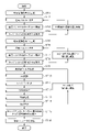
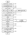
- 4 is a flow chart showing the operation of the laser radar device according to Embodiment 1;
- FIG. 4 is a schematic diagram of a pulse train;
- FIG. 4 is a schematic diagram showing the waveform of a received signal;
- FIG. 4 is a schematic diagram of a received signal waveform and frequency analysis;
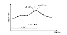
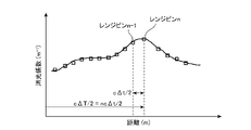
- FIG. 4 is a schematic diagram of the relationship between the distance and the SNR of the received signal; It is a schematic diagram of the signal processing method by a transfer function calculation part.
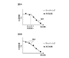
- 9A and 9B are schematic diagrams of the estimated transfer functions, respectively.
- FIG. 4 is a schematic diagram showing distance characteristics of physical parameters;
- FIG. 11 is a block diagram showing a configuration example of a laser radar device according to Embodiment 2;
- FIG. 9 is a block diagram showing a configuration example of an intensity-modulated signal generator according to Embodiment 2; 9 is a flow chart showing the operation of the laser radar device according to Embodiment 2;
- FIG. 14A is a schematic diagram of a pulse train.
- FIG. 14B is a schematic diagram of the transfer function of the evaluated hard target HT.
- FIG. 14C is a schematic diagram of the transfer function of the evaluated volumetric target VT.
- FIG. 15A is a schematic diagram of a pulse train.
- FIG. 15B is a schematic diagram of the transfer function of the evaluated hard target HT.
- FIG. 15C is a schematic diagram of the transfer function of the evaluated volumetric target VT.
- FIG. 11 is a block diagram showing a configuration example of a laser radar device according to Embodiment 3; 10 is a flow chart showing the operation of the laser radar device according to Embodiment 3;
- FIG. 11 is a block diagram showing a configuration example of a laser radar device according to Embodiment 4;
- Embodiment 1 First, a laser radar device according to Embodiment 1 will be described with reference to FIGS. 1 to 10.
- FIG. ⁇ Configuration> A configuration example of a laser radar device according to Embodiment 1 of the present disclosure will be described with reference to FIGS. 1 to 3B. As shown in FIG.
- the laser radar device includes, as an example, a light source 1, an intensity modulator 2, a trigger generation circuit section 3, an intensity modulated signal generation section 4, a pulse signal generation section 5, a pulse modulation section 6 , a transmission side optical system 7 , a transmission/reception separator 8 , a telescope 9 , a reception side optical system 10 , a light receiving section 11 , a signal processing section 12 , and a scanner 13 .
- Light source 1 , intensity modulator 2 , intensity modulated signal generator 4 , pulse signal generator 5 , and pulse modulator 6 constitute light source section 60 .
- the transmitting optical system 7 and the receiving optical system 10 are optional components. In FIG.
- a light source 1 is a light source that emits continuous-wave laser light having a single frequency.
- a light source 1 is connected to an intensity modulator 2 and supplies continuous wave laser light to the intensity modulator 2 .
- the trigger generation circuit unit 3 is connected to the intensity modulated signal generation unit 4, the pulse signal generation unit 5, and the signal processing unit 12, generates a trigger signal (pulse irradiation trigger) for driving these components, and generates a trigger.
- the signal is output to the intensity-modulated signal generator 4 , pulse signal generator 5 and signal processor 12 .
- a pulse generator, a function generator, or an FPGA (field-programmable gate array) can be used as the trigger generation circuit section 3 .
- the intensity-modulated signal generator 4 is connected to the intensity modulator 2 and the signal processor 12 and outputs the generated intensity-modulated signal of frequency fk to the intensity modulator 2 and the signal processor 12 .
- the frequencies f1 to fM are set differently so that signals intensity-modulated at different frequencies are generated.
- Methods of generating different frequencies fk include, for example, a method of generating a signal by giving an offset frequency of ⁇ fk to the frequency signal of f1 using a frequency mixer, and a method of generating a signal with a frequency of a signal generated by a reference signal generator.
- the reference frequency can be generated by multiplying the reference frequency with a multiplier or by dividing it with a frequency divider.
- the reference signals used to generate the intensity-modulated frequency signals need not be the same, and individual reference signals may be prepared for each intensity-modulated frequency.
- a pulse signal generator 5 generates a pulse signal based on the trigger signal.
- the pulse signal generator 5 is connected to the pulse modulator 6 and outputs the generated pulse signal to the pulse modulator 6 .
- the intensity modulator 2 periodically intensity-modulates the continuous wave laser light from the light source 1 based on the intensity-modulated signal output from the intensity-modulated signal generator 4 .
- the intensity modulator 2 for example, an interferometer intensity modulator using an optical attenuator, a semiconductor optical amplifier, an acoustooptic device, or a phase modulator can be used.
- the intensity modulator 2 is connected to the pulse modulating section 6 and outputs an intensity-modulated continuous wave laser beam to the pulse modulating section 6 .
- the pulse modulating section 6 has a pulse modulator, and modulates the intensity-modulated continuous-wave laser light from the intensity modulator 2 based on the pulse signal output from the pulse signal generating section 5, with a repetition period Trep and a pulse width ⁇ T. Pulse modulate to pulse.
- the pulse modulating section 6 for example, an acoustooptic device or a phase modulator can be used.
- the pulse modulating section 6 may include an optical amplifier to amplify the optical power of the pulse-modulated laser light.
- the pulse modulation section 6 is connected to the transmission side optical system 7 and outputs the amplified laser light to the transmission side optical system 7 .
- the light source unit 60 periodically intensity-modulates the continuous-wave laser light with intensity-modulated signals having different frequencies, and outputs a plurality of intensity-modulated pulses with different modulation frequencies.
- periodicically modulating the intensity means that the optical power is modulated so as to change periodically.
- Examples of periodically intensity-modulated pulses are, for example, pulse P1 or pulse P2 in FIG.
- a pulse P1 shows how the optical power changes periodically at the modulation frequency f1 while the maximum value of the optical power is kept constant.
- a pulse P2 shows how the optical power changes periodically at the modulation frequency f2 while the maximum value of the optical power is kept constant.
- the transmission-side optical system 7 shapes the pulse-modulated or amplified laser light from the pulse modulation section 6 into a desired beam diameter and spread angle.
- the transmission-side optical system 7 is composed of a lens group having concave and convex surfaces.
- the transmission-side optical system 7 may be a reflective optical system using a mirror. Since the laser beam is shaped by the transmission-side optical system 7 in order to obtain a high SNR, the transmission-side optical system 7 is not provided if a sufficient SNR can be obtained without the transmission-side optical system 7.
- the transmission-side optical system 7 is connected to the transmission/reception separator 8 and outputs the shaped laser light to the transmission/reception separator 8 .
- the transmission/reception splitter 8 is a splitter that separates transmission light and reception light into predetermined ports.
- a polarizing beam splitter (PBS) can be used as the transmission/reception separator 8 when the laser beam is propagated between the transmission/reception separator 8 and other components by spatial propagation.
- PBS polarizing beam splitter
- the transmission/reception separator 8 is installed between the transmission side optical system 7 and the telescope 9 and on the optical axis of the transmission light.
- a circulator can be used as the transmission/reception separator 8 when the transmission/reception separator 8 and other components are connected by a fiber.
- the transmission/reception splitter 8 outputs transmission light to the telescope 9 and outputs reception light to the reception side optical system 10 .
- the telescope 9 transmits transmitted light in a desired direction via the scanner 13 and receives received light, which is reflected light from the target, via the scanner 13 .
- the telescope 9 is composed of a lens group having concave and convex surfaces.
- the telescope 9 may be a reflective telescope using mirrors.
- the scanner 13 is rotated to face a predetermined direction by a control unit (not shown). Telescope 9 outputs the received light to transmission/reception separator 8 .
- the receiving optical system 10 shapes the received light from the transmission/reception separator 8 into a desired beam diameter and divergence angle.
- the receiving optical system 10 is composed of a lens group having concave and convex surfaces.
- the receiving optical system 10 may be a reflective optical system using a mirror. Since the shaping by the receiving side optical system 10 is to obtain a high SNR, the receiving side optical system 10 may not be provided if a sufficient SNR can be obtained without the receiving side optical system 10 .
- the receiving optical system 10 is connected to the light receiving section 11 and outputs received light to the light receiving section 11 .
- the light receiving unit 11 photoelectrically converts the received light to generate a received electrical signal.
- the light receiving section 11 is connected to the signal processing section 12 and outputs the received electrical signal to the signal processing section 12 .
- the signal processing unit 12 performs signal processing on the received electric signal to calculate the physical distance characteristic.
- the configuration of the signal processing unit 12 will be described below with reference to FIG.
- the signal processing unit 12 includes a filter processing unit 12-1, an A/D conversion unit 12-2, a range bin division unit 12-3, a frequency analysis unit 12-4, an integration processing unit 12 -5, an SNR calculator 12-6, a distance characteristic calculator 12-7, a transfer function calculator 12-8, a physical characteristic calculator 12-9, and a physical distance characteristic calculator 12-10.
- Filter processing section 12 - 1 frequency-filters the received electrical signal from light receiving section 11 based on the intensity-modulated signal of frequency fk from intensity-modulated signal generation section 4 .
- the A/D conversion section 12-2 AD-converts the filtered electrical signal from the filtering section 12-1.
- the A/D conversion section 12-2 is connected to the range bin division section 12-3, and outputs the AD-converted digital signal to the range bin division section 12-3.
- the range bin division unit 12-3 Based on a trigger signal (pulse irradiation trigger), the range bin division unit 12-3 divides the AD-converted digital signal in the time direction by a width corresponding to the pulse width.
- the range bin division unit 12-3 is connected to the frequency analysis unit 12-4 and outputs the divided signal to the frequency analysis unit 12-4.
- the frequency analysis unit 12-4 Based on the intensity-modulated signal of frequency fk from the intensity-modulated signal generator 4, the frequency analysis unit 12-4 performs Fast Fourier Transform (FFT) processing on the divided signals for each bin. convert the binned signal to a spectrum with .
- the frequency analysis section 12-4 is connected to the integration processing section 12-5 and outputs the spectrum to the integration processing section 12-5.
- the integration processing unit 12-5 integrates a plurality of spectra obtained from a plurality of shots of data of the same frequency fk in the spectral space. Integration processing section 12-5 is connected to SNR calculation section 12-6 and outputs the spectrum after integration to SNR calculation section 12-6.
- the SNR calculator 12-6 calculates the SNR of the received signal at a certain time and a certain intensity modulation frequency.
- the SNR calculator 12-6 is connected to the distance characteristic calculator 12-7 and outputs the calculated SNR to the distance characteristic calculator 12-7.
- the distance characteristic calculator 12-7 calculates the relationship between distance and SNR (distance characteristic: A-scope) at a certain intensity modulation frequency.
- the distance characteristic calculator 12-7 calculates the A-scope for all of the intensity modulation frequencies f1 to fM.
- the distance characteristic calculator 12-7 is connected to the transfer function calculator 12-8, and outputs the calculated plurality of distance characteristics (A-scope) to the transfer function calculator 12-8.
- the transfer function calculator 12-8 calculates a target transfer function in a certain range bin from a plurality of distance characteristics (A-scope) of a plurality of intensity modulated frequencies (f1 to fM) for that range bin. In this manner, the transfer function calculator 12-8 analyzes the transfer function characteristics of targets in the same range from the frequency dependence of SNR.
- the transfer function calculator 12-8 is connected to the physical property calculator 12-9, and outputs the calculated transfer function to the physical property calculator 12-9.
- the physical property calculation unit 12-9 calculates the transfer function characteristics found from the transfer function in each range bin n obtained by the transfer function calculation unit 12-8, and the transfer function expression by equation (4) or equation (6) described later, or By comparing the transfer function formula with formulas similar to these formulas, the physical properties of the target existing in the range bin n are calculated. Further, the physical property calculation unit 12-9 compares the SNR in each range bin n obtained by the distance property calculation unit 12-7 with the assumed SNR, thereby calculating the physical property of the target existing in the range bin n. can be calculated. The physical property calculator 12-9 is connected to the physical distance property calculator 12-10, and outputs the calculated physical property to the physical property distance property calculator 12-10.
- the signal processor 12 is implemented by a processing circuit 100a.
- the processing circuit 100a is, for example, a single circuit, a composite circuit, a programmed processor, a parallel programmed processor, an ASIC (Application Specific Integrated Circuit), an FPGA (Field-Programmable Gate Array), or a combination thereof.
- the functions of the components included in the signal processing unit 12 may be realized by separate processing circuits, or the functions of a plurality of components may be collectively realized by one processing circuit.
- the signal processing unit 12 is realized by a processor 100b and a memory 100c.
- a program stored in the memory 100c is read out by the processor 100b and executed, thereby realizing the functions of the components included in the signal processing unit 12.
- FIG. Programs may be implemented as software, firmware, or a combination of software and firmware.
- Examples of the memory 100c include non-volatile or volatile semiconductors such as RAM (Random Access Memory), ROM (Read Only Memory), flash memory, EPROM (Erasable Programmable Read Only Memory), and EEPROM (Electrically-EPROM). Memory, magnetic disk, flexible disk, optical disk, compact disk, mini disk, DVD are included.
- step ST1 the intensity-modulated signal generator 4 generates an intensity-modulated signal of frequency f1 based on the trigger signal, and outputs the generated intensity-modulated signal of frequency f1 to the intensity modulator 2 and the signal processor 12. Subsequently, the intensity modulator 2 periodically intensity-modulates the single-frequency continuous-wave laser beam from the light source 1 with an intensity-modulated signal of frequency f1, and converts the intensity-modulated continuous-wave laser beam to a pulse modulating section. Output to 6.
- step ST2 the pulse modulating section 6 pulse-modulates the intensity-modulated continuous wave laser light into pulsed light P1 having a predetermined repetition period Trep and a pulse width .delta.T based on the pulse signal from the pulse signal generating section 5.
- pulsed light P1 is output to the transmission side optical system 7 .
- the k-th transmission pulse signal is written as "Pk”.
- the intensity-modulated frequency corresponding to the transmitted pulse Pk and the received signal pulse from the target are denoted by fk and Rk, respectively.
- step ST3 the telescope 9 irradiates the target through the scanner 13 with the pulsed light P1 that has been converted into a predetermined beam diameter and beam divergence angle by the transmitting optical system 7.
- a target is irradiated with the transmitted light P1 irradiated into the atmosphere, and a received light R1 is generated when the transmitted light P1 is scattered by the target.
- step ST4 the telescope 9 receives the received light R1 through the aperture and outputs the received light R1 to the transmission/reception separator 8.
- the received light R1 is sent to the receiving side optical system 10 via the transmitting/receiving separator 8 .
- the received light R1 is converted into a predetermined beam diameter and beam divergence angle by the receiving optical system 10 and then sent to the light receiving section 11 .
- the received light R1 is converted into a received electrical signal by the light receiving section 11 and the received electrical signal is sent to the signal processing section 12 .
- the laser radar device repeats the above transmission/reception processing from steps ST2 to ST4 a times.
- a is an integer greater than or equal to 1 and is a designed value.
- this a will be referred to as the number of pulse integrations. That is, a is the number of integration times for the same intensity-modulated pulse.
- the intensity-modulated signal generator 4 generates an intensity-modulated signal of frequency f2 based on the trigger signal. , and outputs the generated intensity-modulated signal of frequency f2 to the intensity modulator 2 and the signal processing unit 12 .
- the intensity modulator 2 periodically intensity-modulates the single-frequency continuous-wave laser beam from the light source 1 with an intensity-modulated signal of frequency f2, and converts the intensity-modulated continuous-wave laser beam to a pulse modulating section. Output to 6.
- step ST6 the pulse modulating section 6 pulse-modulates the intensity-modulated continuous wave laser light based on the pulse signal from the pulse signal generating section 5 to generate pulsed light P2 different from the pulsed light P1 (see FIG. 5). pulse P2), and outputs the generated pulsed light P2 to the transmission side optical system 7.
- step ST7 the telescope 9 irradiates the target through the scanner 13 with the pulsed light P2 that has been converted into a predetermined beam diameter and beam divergence angle by the transmission-side optical system 7.
- a target is irradiated with the transmitted light P2 irradiated into the atmosphere, and a received light R2 is generated when the transmitted light P2 is scattered by the target.
- step ST8 the telescope 9 receives the received light R2 through the aperture and outputs the received light R2 to the transmission/reception separator 8.
- the received light R2 is sent to the receiving side optical system 10 via the transmitting/receiving separator 8 .
- the received light R2 is converted into a predetermined beam diameter and beam divergence angle by the receiving optical system 10 and then sent to the light receiving section 11 .
- the received light R 2 is converted into a received electrical signal by the light receiving section 11 and the received electrical signal is sent to the signal processing section 12 .
- each of the received lights R1 to RM is received a times.
- step ST4 signal processing related to steps ST9 to ST14 will be described.
- the signal processing may be performed each time each received light is obtained following step ST4, or may be performed after all the received lights R1 to RM are obtained following step ST8.
- the signal processing in steps ST9 to ST14 will be described below assuming that it is performed after all the received lights R1 to RM are obtained.
- step ST9 the filter processing unit 12-1 frequency-filters the received signals of all the received lights (R1 and Rk) based on the intensity-modulated signal of frequency fk from the intensity-modulated signal generator 4. An electrical signal corresponding to the modulation frequency is obtained.
- the A/D converter 12-2 AD-converts the received signal of the received light Rk.
- the A/D conversion section 12-2 uses the trigger signal from the trigger generation circuit section 3 as a start trigger for AD conversion. Therefore, the start time of AD conversion substantially coincides with the timing at which the transmission pulse is transmitted, and AD conversion is continued for a predetermined period or until the next transmission pulse occurs.
- the digitized received signal corresponds to one pulse.
- step ST11 the range bin dividing section 12-3 divides the digitized received signal into signals for each range bin. Range bin widths are delimited to correspond to pulse widths, which are determined by design.
- FIG. 6A shows the time variation of the received signal obtained by receiving the received light Rk from the target irradiated with one pulse of the pulsed transmission light Pk.
- n represents the label of the divided range bin, and a label with a small value of n indicates a reflected signal from a closer neighborhood.
- the frequency analysis section 12-4 converts the received signal divided for each range bin into a spectrum signal by FFT for each range bin, and outputs the obtained spectrum signal to the integration processing section 12-5.
- the spectrum obtained by FFTing the received signal of the received light Rk corresponding to the transmission pulse Pk (modulation frequency fk) is subject to frequency shift due to the target and the environment, but substantially matches the modulation frequency within the reception bandwidth B.
- the reception spectrum corresponding to the modulation frequency fk is written as fm.
- the reception bandwidth B is an assumed frequency shift width determined by the moving speed of the target and the surrounding environment.
- step ST13 the integration processing unit 12-5 integrates the spectrum signal obtained by FFT for the signal of each range bin a times, as shown in FIG. 6B.
- step ST14 the SNR calculator 12-6 calculates the SNR of the received signal spectrum fm by calculating the ratio of the peak intensity to the out-of-band noise.
- the SNR calculator 12-6 outputs the spectrum fm after integration and SNR information in each range bin to the distance characteristic calculator 12-7.
- the physical property calculation unit 12-9 calculates the physical property of the target existing in the range bin n. Specifically, the physical property calculation unit 12-9 calculates the transfer function characteristics found from the transfer function in each range bin n obtained by the transfer function calculation unit 12-8, and the following formula (4) or formula (6) By comparing the transfer function equations by or similar equations to these equations, the physical properties of the target present in the range bin n are calculated. Further, the physical property calculation unit 12-9 compares the SNR in each range bin n obtained by the distance property calculation unit 12-7 with the assumed SNR, thereby calculating the physical property of the target existing in the range bin n. can be calculated.
- the transfer function characteristic is the full shape of the graph as shown in FIG. 9A or FIG. 9B, the slope of the graph, or the cutoff frequency fc when the graph is regarded as equivalent to the transfer function of the low-pass filter. is.
- v is the propagation velocity within the volume target VT
- t is time
- A is a system coefficient
- Y is a normalization constant.
- Equation (4) the modulation frequency ⁇ m component of the received signal obtained is expressed by Equation (4).
- the target transfer function T( ⁇ ) is given by equation (4), which is equivalent to the case of a first-order low-pass filter (LPF).
- the cutoff frequency fc of the transfer function is expressed by Equation (5) using the extinction coefficient c under the assumption of Equation (2).
- a physical parameter eg, extinction coefficient c
- FIG. 9A shows fitting by the transfer function formula of formula (4)
- FIG. 9B shows fitting by the transfer function formula of formula (6).
- the cutoff frequency fc is obtained by comparing the transfer function characteristics based on the measurement results with a transfer function formula such as formula (4), and the extinction coefficient c from formula (5) Calculate
- the extinction coefficient c in equation (1) is expressed using the absorption coefficient ⁇ and the scattering coefficient b (or the backscattering coefficient ⁇ ) as in the following equation (7). Note that ⁇ is the solid angle of the transmission/reception optical system.
- Equation (7) Since the extinction coefficient c is correlated with two or more physical parameters, as expressed by Equation (7), the prior art assumes a certain relationship between these parameters. For example, in designing a laser sensor, a linear relationship was assumed between the backscattering coefficient ⁇ and the extinction coefficient c, and the ratio of them was defined as the lidar ratio S1, and the following equation (8) was assumed.
- the lidar ratio S1 is determined by the particle size, laser wavelength ⁇ , particle shape, and the like. A target to be measured is determined, and the backscattering coefficient of the target is calculated by using the lidar ratio S1, which has been determined by simulation or other measurements, and equations ( 1 ) and (8).
- the transfer function of the data output from the transfer function calculator 12-8 has extinction coefficient information
- the SNR output from the SNR calculator 12-6 has extinction coefficient and scattering coefficient information
- a problem with conventional laser radar equipment is that it is impossible to calculate the extinction coefficient and the scattering coefficient independently. Since the relationship between the coefficients was formulated after approximation, there was a problem that the measured physical property parameters were incorrectly calculated when the accuracy of the measured value was low or when the target was different from the assumption and unknown. Using the technique of the present disclosure eliminates the need to formulate the relationship between the extinction coefficient and the scattering coefficient, thus solving the problems of conventional laser radar devices.
- a pulse laser generation method not only the method of making a continuous wave laser pulse, but also general methods such as the method of directly generating a pulse wave laser such as a Q-switched laser or a mode-locked laser, or a combination thereof. may be used.
- Methods for generating intensity-modulated pulses include an electro-absorption modulator, an electro-optic crystal, an optical block, or the like, or a method of generating intensity-modulated pulses using an intensity modulator created using them, a light source is directly excited by an electric signal pulse train to generate a pseudo intensity-modulated pulse, and a pulsed laser is split by a beam splitter, and one of the pulses is delayed and combined again to generate a pseudo intensity-modulated pulse.
- a method of generating a pulse, or a method of generating a pseudo intensity-modulated pulse by installing a wavelength conversion crystal in a resonator in which the reflectance of only one side of the mirror is lowered may be used.
- the technology of the present disclosure may be applied to a coherent lidar, a differential absorption lidar, and a dual polarization lidar as long as an intensity-modulated pulse is used as transmitted light.
- a coherent lidar the moving speed of the target can be calculated in addition to the physical property information of the target, so it is possible to measure many parameters with higher accuracy.
- the light source section outputs an intensity-modulated pulse of a first wavelength and an intensity-modulated pulse of a second wavelength different from the first wavelength
- the signal processing section outputs an intensity-modulated pulse of the first wavelength.
- the absorption wavelength and concentration of the target can be further calculated as the physical property information of the target.
- the light source unit When applied to a double-polarized lidar, the light source unit outputs intensity-modulated pulses with two orthogonal polarization states, and the signal processing unit uses the received signal intensity ratio of the two polarizations to obtain target physical property information. Particle shape can be further calculated. Also, in the optical system, although it is assumed that the optical system is a transmission/reception optical system, it may be configured with separate transmission/reception shafts.
- a telescope (not shown) different from the telescope 9 is connected to the reception side optical system 10, and the transmission/reception separating section 8 and the reception side optical system 10 are not connected.
- Such a configuration of separate transmission and reception shafts is common and does not affect the operation of the first embodiment.
- Embodiment 2 The laser radar device according to the second embodiment will be described below with reference to FIGS. 11 to 13. FIG.
- the overall configuration of the laser radar device according to the second embodiment is similar to that of the laser radar device according to the first embodiment shown in FIG.
- the light source unit 60A includes a light source 1, an intensity modulator 2, an intensity modulated signal generator 4A, a pulse signal generator 5, and a pulse modulator.
- a part 6 is provided in the laser radar apparatus according to the second embodiment.
- the configuration of the intensity modulated signal generator 4A included in the light source section 60A is different from that of the intensity modulated signal generator 4 of the first embodiment.
- the intensity-modulated signal generation unit 4A includes an intensity-modulated signal (f) generation unit group 4-1 consisting of M intensity-modulated signal (f) generation units, and an intensity-modulated signal (f) generation unit group 4-1. ) An intensity modulated signal mixer 4-2 connected to the generator group 4-1.
- the intensity-modulated signal (f) generator group 4-1 generates intensity-modulated signals of M different frequencies.
- the intensity-modulated signal (f) generator group 4-1 is composed of a function generator, an FPGA, a reference signal generator, a multiplier, or an RF frequency signal generator such as a frequency divider.
- the intensity-modulated signal mixer 4-2 mixes the M intensity-modulated signals from the intensity-modulated signal (f) generator group 4-1.
- the intensity-modulated signal mixer 4-2 is composed of, for example, an RF frequency mixer.
- Embodiment 1 pulses were generated by intensity-modulating a laser beam with a certain intensity modulation frequency fk, and each of M kinds of pulses was irradiated a times for integration.
- intensity-modulated signals having M different frequencies (f1 to fM) are applied to the transmission pulse at the same time, and the transmission pulse is irradiated a times for integration.
- the operation of the second embodiment differs from that of the first embodiment in this respect. Otherwise, the operation of the second embodiment is the same as the operation of the first embodiment. Differences will be described with reference to FIG. 13 . be.
- the intensity-modulated signal (f) generation unit group 4-1 generates intensity-modulated signals of frequencies f1 to fM based on the trigger signal, and converts M intensity-modulated signals of frequencies f1 to fM into intensity-modulated signals. It outputs to the mixer 4-2 and the signal processor 12.
- FIG. 1 the intensity-modulated signal (f) generation unit group 4-1 generates intensity-modulated signals of frequencies f1 to fM based on the trigger signal, and converts M intensity-modulated signals of frequencies f1 to fM into intensity-modulated signals. It outputs to the mixer 4-2 and the signal processor 12.
- the intensity-modulated signal mixer 4-2 mixes M intensity-modulated signals.
- the intensity modulated signal mixer 4 - 2 outputs the mixed signal to the intensity modulator 2 .
- the intensity modulated signal mixer 4-2 may output the mixed signal to the signal processor 12.
- FIG. Following the operation of the intensity-modulated signal mixer 4-2, the intensity modulator 2 intensity-modulates the single-frequency continuous-wave laser light from the light source 1 with the mixed intensity-modulated signal, producing an intensity-modulated continuous wave A laser beam is output to the pulse modulation unit 6 .
- step ST23 the pulse modulating section 6 pulse-modulates the intensity-modulated continuous wave laser light into pulsed light P based on the pulse signal from the pulse signal generating section 5, and transmits the pulsed light P to the transmitting side optical system 7. Output.
- step ST24 the telescope 9 irradiates the target through the scanner 13 with the pulsed light P converted into a predetermined beam diameter and beam divergence angle by the transmitting optical system 7.
- a target is irradiated with the transmitted light P irradiated into the atmosphere, and received light R is generated when the transmitted light P is scattered by the target.
- the telescope 9 receives the received light R through the aperture and outputs the received light R to the transmission/reception separator 8.
- the received light R is sent to the receiving side optical system 10 via the transmitting/receiving separator 8 .
- the received light R is converted into a predetermined beam diameter and beam divergence angle by the receiving optical system 10 , and then sent to the light receiving section 11 .
- the received light R is converted into a received electrical signal by the light receiving section 11 and the received electrical signal is sent to the signal processing section 12 .
- the laser radar device repeats the transmission/reception processing from steps ST23 to ST25 a times.
- step ST26 to step ST33 is the same as the processing from step ST9 to step ST16 in the first embodiment.
- Embodiment 3 The laser radar device according to the third embodiment will be described below with reference to FIGS. 14 to 17.
- FIG. 1 the non-uniformity of the pulse power or the degree of intensity modulation between the intensity-modulated pulses that occurs when each pulse Pk is intensity-modulated with the frequency fk causes the transfer function characteristics to be calculated. error may occur. Change paragraphs to explain.
- the pulse parameter represents the envelope shape of each intensity-modulated pulse, the peak component forming each intensity-modulated pulse, the intensity-modulated frequency given to the light pulse, and similar parameters.
- the difference in the pulse parameters refers to the envelope shape of each intensity-modulated pulse, the peak component that constitutes each intensity-modulated pulse, the intensity-modulated frequency given to the light pulse, and the difference from the ideal values of such parameters. show.
- the laser radar apparatus monitors part of the intensity-modulated pulse signal and performs control to optimize the pulse parameters of each pulse (P1 to PM). It is configured to calculate a more accurate transfer function.
- the laser radar device according to Embodiment 3 differs from the laser radar device according to Embodiment 1 in the following points. That is, as shown in FIG. 16, the laser radar device according to the third embodiment further includes an optical pulse splitter 14, an optical pulse monitor 15, and an optical pulse corrector 16.
- FIG. The optical pulse splitter 14 is provided between the pulse modulator 6 and the transmission-side optical system 7 .
- the optical pulse monitor section 15 is provided after the optical pulse branching section 14 .
- the optical pulse correction section 16 is provided in the subsequent stage of the optical pulse monitor section 15, and is connected to the intensity modulated signal generation section 4B and the pulse signal generation section 5B.
- the light source 1, the intensity modulator 2, the intensity modulated signal generator 4B, the pulse signal generator 5B, and the pulse modulator 6 constitute a light source section 60B.
- the laser radar apparatus according to the second embodiment may be modified so as to add the optical pulse branching unit 14, the optical pulse monitor unit 15, and the optical pulse correction unit 16 to the laser radar apparatus according to the second embodiment. good.
- the optical pulse splitter 14 splits a part of the intensity-modulated pulse generated by the pulse modulator 6 and outputs the split pulse to the optical pulse monitor 15 .
- the optical pulse monitor unit 15 converts the optical pulse signal into an electrical signal.
- the optical pulse correction unit 16 compares the electrical signal from the optical pulse monitor unit 15 with an ideal intensity-modulated pulse waveform held in advance, and the pulse waveform output from the pulse modulation unit becomes ideal.
- a feedback signal is output to the intensity modulated signal generator 4 and the pulse signal generator 5 .
- the optical pulse corrector 16 outputs a feedback signal for controlling the pulse power and modulation intensity of the transmission pulse.
- the optical pulse monitor section 15 receives the optical pulse signal as the monitor signal branched from the optical pulse branch section 14, and converts the received optical pulse signal into an electrical signal.
- step ST42 the optical pulse correction unit 16 compares the waveform of the electrical signal from the optical pulse monitor unit 15 with an ideal intensity-modulated pulse waveform held in advance, and the deviation of these waveforms is suppressed.
- the feedback signal is output to the intensity modulated signal generator 4 and the pulse signal generator 5 so that the waveform of the pulse output from the pulse modulator becomes ideal.
- step ST1 after the feedback signal is generated, the intensity-modulated signal generator 4B generates an intensity-modulated signal of frequency f1 based on the feedback signal, and transmits the generated intensity-modulated signal of frequency f1 to the intensity modulator 2 and the signal Output to the processing unit 12 .
- the intensity modulator 2 intensity-modulates the single-frequency continuous-wave laser beam from the light source 1 with an intensity-modulated signal of frequency f1 generated based on the feedback signal, and the intensity-modulated continuous-wave laser beam The light is output to the pulse modulating section 6 .
- step ST2 after the feedback signal is generated, the pulse modulating section 6 pulse-modulates the intensity-modulated continuous wave laser light based on the pulse signal generated based on the feedback signal from the pulse signal generating section 5. do.
- a monitor signal is received by the optical pulse monitor unit 15 in step ST43, and a feedback signal is generated in ST44.
- An intensity-modulated signal of frequency fk is generated based on the feedback signal (step ST5), and a pulse Pk is generated based on the feedback signal.
- the laser radar device According to the laser radar device according to the third embodiment, it is possible to suppress the difference from the ideal values of the pulse power and the degree of intensity modulation between the intensity-modulated pulses that occurs when each pulse Pk is intensity-modulated with the frequency fk. Therefore, it is possible to prevent errors from occurring in the calculated transfer function characteristics.
- Embodiment 4 the laser radar device according to Embodiment 4 will be described with reference to FIGS. 18 to 20.
- FIG. In the laser radar system according to the fourth embodiment, similarly to the laser radar system according to the third embodiment, the pulse power and the degree of intensity modulation between the intensity-modulated pulses generated when each pulse Pk is intensity-modulated with the frequency fk are determined. The purpose is to correct errors in transfer function characteristics calculated from non-uniformity. The method of achieving this object differs between the laser radar device according to the fourth embodiment and the laser radar device according to the third embodiment.
- the laser radar device of the fourth embodiment monitors a part of the intensity-modulated pulse signal to observe the actual intensity-modulated pulse parameters with respect to the ideal intensity-modulated pulse parameters, and based on the information, It is configured to calculate the uncertainty of the received signal, such as the error of the transfer function that may occur in the transmission function, and correct the detected SNR using that information to calculate a more accurate transfer function. Details will be described below.
- the laser radar device according to Embodiment 4 differs from the laser radar device according to Embodiment 1 in the following points. That is, as shown in FIG. 18, the laser radar device according to the fourth embodiment further includes an optical pulse splitter 14 and an optical pulse monitor 15A.
- the optical pulse splitter 14 is provided between the pulse modulator 6 and the transmission-side optical system 7 .
- the optical pulse monitor section 15A is provided after the optical pulse branching section 14 .
- the optical pulse monitor section 15A is electrically connected to the signal processing section 12A.
- the optical pulse monitor section 15A converts the optical pulse signal into an electrical signal and supplies the converted electrical signal to the signal processing section 12A as an optical pulse monitor signal. Further, as shown in FIG.
- the signal processing section 12A further includes a transfer function calculation correction section 12-11.
- the transfer function calculation correction unit 12-11 is provided in the signal processing unit 12 between the transfer function calculation unit 12-8 and the physical property calculation unit 12-9.
- the light source 1, the intensity modulator 2, the intensity modulated signal generator 4, the pulse signal generator 5, and the pulse modulator 6 constitute the light source section 60 as in the first embodiment.
- the laser radar device according to the second embodiment is modified so that the optical pulse branching unit 14, the optical pulse monitor unit 15A, and the transfer function calculation correction unit 12-11 are added to the laser radar device according to the second embodiment. You may
- the optical pulse splitter 14 splits a part of the intensity-modulated pulse generated by the pulse modulator 6, and outputs the split pulse to the optical pulse monitor 15A.
- the optical pulse monitor unit 15A converts the optical pulse signal into an electrical signal (optical pulse monitor signal).
- the transfer function calculation correction unit 12-11 makes the spectral characteristics of the electric signal (optical pulse monitor signal) from the optical pulse monitor unit 15A and the received signal from the target having the same frequency response characteristics uniform.
- the output from the transfer function calculator 12-8 is corrected by comparing with the information on the optimum driving condition of the intensity modulated pulse.
- the information includes an ideal intensity-modulated pulse waveform.
- the operation of the laser radar system of the fourth embodiment is different from the operation of the laser radar system of the third embodiment in that the process of step ST55 is added and the process performed after the step of receiving the monitor signal (ST41A). is the processing of step ST55.
- the process of step ST55 is added and the process performed after the step of receiving the monitor signal (ST41A). is the processing of step ST55.
- steps ST51 to ST54 in FIG. 20 are substantially the same as steps ST1 to ST8 in FIG. 17 according to the third embodiment. 20 is different from the process shown in FIG. 17 in that the process of generating a feedback signal based on the monitor signal (steps ST41 to ST44) is omitted. Because it does.
- the laser radar device of the fourth embodiment may also perform processing (steps ST41 to ST44) of generating a feedback signal based on the monitor signal, as in the third embodiment.
- the optical pulse monitor unit 15A receives the optical pulse signal as the monitor signal branched from the optical pulse branch unit 14, converts the received optical pulse signal into an electrical signal, and converts the electrical signal into an electrical signal.
- the signal is supplied as an optical pulse monitor signal to the transfer function calculation correction section 12-11 of the signal processing section 12A.
- the transfer function calculation correction unit 12-11 combines the waveform of the electrical signal (optical pulse monitor signal) from the optical pulse monitor unit 15 acquired in step ST41A with the previously held ideal intensity modulated pulse.
- the transfer function is corrected by comparing the waveforms, predicting or calculating the error in the transfer function calculation result that may arise from the deviation of these waveforms, and correcting the error.
- the correction by the transfer function calculation correction unit 12-11 is performed after the integration process and after the SNR calculation. You may modify
- the transfer function calculation correction unit 12-11 is provided between the frequency analysis unit 12-4 and the integration processing unit 12-5, and step ST55 is performed immediately after step ST12.
- the transfer function calculation correction unit 12-11 is provided between the integration processing unit 12-5 and the SNR calculation unit 12-6, and step ST55. is performed immediately after step ST13.
- the transfer function characteristic calculated from the non-uniformity of the pulse power and the degree of intensity modulation between the intensity-modulated pulses generated when each pulse Pk is intensity-modulated with the frequency fk. error can be corrected, and more accurate physical properties can be calculated.
- the laser radar device of the present disclosure can be used as a laser radar device for calculating physical property parameters such as the extinction coefficient of a target.
Abstract
This laser radar device is equipped with: light source units (60, 60A, 60B) for outputting a plurality of intensity-modulated pulses by periodically modulating the intensity of a laser beam by using intensity modulation signals of different frequencies; a telescope (9) for transmitting a plurality of intensity-modulated pulses to a target and receiving reflected light from the target as received light; a light-receiving unit (11) for generating a received electrical signal by photoelectrically converting the received light; and a signal processing unit (12) for calculating the target distance and property parameters on the basis of the received electrical signal.
Description
本開示はレーザレーダ装置に関する。
This disclosure relates to a laser radar device.
レーザレーダ装置による距離計測の手法として、強度変調パルスToF(Time of Flight)方式と呼ばれる手法がある。強度変調パルスToF方式とは、発光開始から受光までのパルス飛行時間からターゲットまでの距離を求めるパルスToF方式のうち、光パルスに対して周期的な強度変調を加えることで、散乱の強いボリュームターゲットVT中に存在するハードターゲットHTからの反射信号(HT信号)の信号対雑音比(SNR:Signal-to-noise ratio)を上げてHT信号を抽出し、ハードターゲットHTの位置を算出する手法のことをいう。非特許文献1は強度変調パルスToF方式に関する文献であり、非特許文献1にはパルスの合分波方式により生成された、疑似的に単一強度変調周波数で強度変調したパルスを用いて、ボリュームターゲットVT(volume target)中のハードターゲットHT(hard target)を識別する装置に関する記載がなされている。
As a method of distance measurement using a laser radar device, there is a method called the intensity-modulated pulse ToF (Time of Flight) method. The intensity-modulated pulse ToF method is one of the pulse ToF methods that obtains the distance to the target from the pulse flight time from the start of light emission to the light reception. A method of extracting the HT signal by increasing the signal-to-noise ratio (SNR) of the reflected signal (HT signal) from the hard target HT present in the VT and calculating the position of the hard target HT. Say things. Non-Patent Document 1 is a document related to the intensity-modulated pulse ToF method. An apparatus for identifying a hard target HT (hard target) in a target VT (volume target) is described.
非特許文献1に記載の技術によれば、ターゲットの位置を算出できるが、ターゲットの消光係数などの物性パラメータを算出できないという課題がある。
According to the technique described in Non-Patent Document 1, the position of the target can be calculated, but there is a problem that the physical parameters such as the extinction coefficient of the target cannot be calculated.
本開示は、このような課題を解決するためになされたものであり、ターゲットの消光係数などの物性パラメータを算出できる強度変調パルスToF方式のレーザレーダ装置を提供することを目的とする。
The present disclosure has been made to solve such problems, and aims to provide an intensity-modulated pulse ToF laser radar device capable of calculating physical parameters such as the extinction coefficient of a target.
本開示の実施形態によるレーザレーダ装置は、レーザ光を互いに異なる周波数の強度変調信号により周期的に強度変調して複数の強度変調パルスを出力する光源部と、前記複数の強度変調パルスをターゲットに送信し、前記ターゲットによる反射光を受信光として受信するテレスコープと、前記受信光を光電変換して受信電気信号を生成する受光部と、前記受信電気信号に基づいて前記ターゲットの距離および物性パラメータを算出する信号処理部と、を備える。
A laser radar device according to an embodiment of the present disclosure includes a light source unit that periodically intensity-modulates laser light with intensity-modulated signals of mutually different frequencies and outputs a plurality of intensity-modulated pulses, and a light source unit that outputs a plurality of intensity-modulated pulses. a telescope for transmitting and receiving light reflected by the target as received light; a light receiving unit for photoelectrically converting the received light to generate a received electrical signal; and distance and physical property parameters of the target based on the received electrical signal. and a signal processing unit that calculates
本開示の実施形態によるレーザレーダ装置は、ターゲットの消光係数などの物性パラメータを算出できる。
The laser radar device according to the embodiment of the present disclosure can calculate physical parameters such as the extinction coefficient of the target.
以下、図1から図17を参照して、本開示における種々の実施形態について詳細に説明する。なお、図面において同一または類似の符号を付された構成要素は、同一または類似の構成または機能を有するものであり、そのような構成要素についての重複する説明は省略する。
Various embodiments of the present disclosure will be described in detail below with reference to FIGS. Components denoted by the same or similar reference numerals in the drawings have the same or similar configurations or functions, and duplicate descriptions of such components will be omitted.
実施の形態1.
まず、図1から図10を参照して、実施の形態1によるレーザレーダ装置について説明する。
<構成>
図1から図3Bを参照して、本開示の実施の形態1によるレーザレーダ装置の構成例について説明する。図1に示すとおり、実施の形態1によるレーザレーダ装置は、一例として、光源1、強度変調器2、トリガ生成回路部3、強度変調信号生成部4、パルス信号生成部5、パルス変調部6、送信側光学系7、送受分離器8、テレスコープ9、受信側光学系10、受光部11、信号処理部12、およびスキャナ13を備える。光源1、強度変調器2、強度変調信号生成部4、パルス信号生成部5、およびパルス変調部6は、光源部60を構成する。送信側光学系7および受信側光学系10は、選択的な構成部である。図1において、黒太矢印は送信光の流れを示し、白太矢印は受信光の流れを示し、細矢印は電気信号の流れを示す。光源1と強度変調器2の間、強度変調器2とパルス変調部6の間、パルス変調部6と送信側光学系7の間、送信側光学系7と送受分離器8の間、送受分離器8とテレスコープ9の間、送受分離器8と受信側光学系10の間、受信側光学系10と受光部11の間の光路は、例えば光ファイバにより実現できる。テレスコープ9とスキャナ13の間は自由空間である。電気信号が流れる電気経路は電気配線により実現される。Embodiment 1.
First, a laser radar device according toEmbodiment 1 will be described with reference to FIGS. 1 to 10. FIG.
<Configuration>
A configuration example of a laser radar device according toEmbodiment 1 of the present disclosure will be described with reference to FIGS. 1 to 3B. As shown in FIG. 1, the laser radar device according to Embodiment 1 includes, as an example, a light source 1, an intensity modulator 2, a trigger generation circuit section 3, an intensity modulated signal generation section 4, a pulse signal generation section 5, a pulse modulation section 6 , a transmission side optical system 7 , a transmission/reception separator 8 , a telescope 9 , a reception side optical system 10 , a light receiving section 11 , a signal processing section 12 , and a scanner 13 . Light source 1 , intensity modulator 2 , intensity modulated signal generator 4 , pulse signal generator 5 , and pulse modulator 6 constitute light source section 60 . The transmitting optical system 7 and the receiving optical system 10 are optional components. In FIG. 1, thick black arrows indicate the flow of transmitted light, thick white arrows indicate the flow of received light, and thin arrows indicate the flow of electrical signals. Between the light source 1 and the intensity modulator 2, between the intensity modulator 2 and the pulse modulation section 6, between the pulse modulation section 6 and the transmission side optical system 7, between the transmission side optical system 7 and the transmission/reception separator 8, and the transmission/reception separation Optical paths between the transmitter/receiver 8 and the telescope 9, between the transmitter/receiver separator 8 and the receiving side optical system 10, and between the receiving side optical system 10 and the light receiving section 11 can be realized by optical fibers, for example. Between telescope 9 and scanner 13 is free space. An electric path through which an electric signal flows is realized by an electric wiring.
まず、図1から図10を参照して、実施の形態1によるレーザレーダ装置について説明する。
<構成>
図1から図3Bを参照して、本開示の実施の形態1によるレーザレーダ装置の構成例について説明する。図1に示すとおり、実施の形態1によるレーザレーダ装置は、一例として、光源1、強度変調器2、トリガ生成回路部3、強度変調信号生成部4、パルス信号生成部5、パルス変調部6、送信側光学系7、送受分離器8、テレスコープ9、受信側光学系10、受光部11、信号処理部12、およびスキャナ13を備える。光源1、強度変調器2、強度変調信号生成部4、パルス信号生成部5、およびパルス変調部6は、光源部60を構成する。送信側光学系7および受信側光学系10は、選択的な構成部である。図1において、黒太矢印は送信光の流れを示し、白太矢印は受信光の流れを示し、細矢印は電気信号の流れを示す。光源1と強度変調器2の間、強度変調器2とパルス変調部6の間、パルス変調部6と送信側光学系7の間、送信側光学系7と送受分離器8の間、送受分離器8とテレスコープ9の間、送受分離器8と受信側光学系10の間、受信側光学系10と受光部11の間の光路は、例えば光ファイバにより実現できる。テレスコープ9とスキャナ13の間は自由空間である。電気信号が流れる電気経路は電気配線により実現される。
First, a laser radar device according to
<Configuration>
A configuration example of a laser radar device according to
(光源)
光源1は単一周波数からなる連続波レーザ光を出射する光源である。光源1は強度変調器2に接続され、連続波レーザ光を強度変調器2に供給する。 (light source)
Alight source 1 is a light source that emits continuous-wave laser light having a single frequency. A light source 1 is connected to an intensity modulator 2 and supplies continuous wave laser light to the intensity modulator 2 .
光源1は単一周波数からなる連続波レーザ光を出射する光源である。光源1は強度変調器2に接続され、連続波レーザ光を強度変調器2に供給する。 (light source)
A
(トリガ生成回路部)
トリガ生成回路部3は、強度変調信号生成部4、パルス信号生成部5および信号処理部12に接続され、これらの構成部を駆動するためのトリガ信号(パルス照射トリガ)を生成して、トリガ信号を強度変調信号生成部4、パルス信号生成部5および信号処理部12へ出力する。トリガ生成回路部3として、例えば、パルスジェネレータ、ファンクションジェネレータ、またはFPGA(field-programmable gate array)を用いることができる。 (trigger generation circuit)
The triggergeneration circuit unit 3 is connected to the intensity modulated signal generation unit 4, the pulse signal generation unit 5, and the signal processing unit 12, generates a trigger signal (pulse irradiation trigger) for driving these components, and generates a trigger. The signal is output to the intensity-modulated signal generator 4 , pulse signal generator 5 and signal processor 12 . For example, a pulse generator, a function generator, or an FPGA (field-programmable gate array) can be used as the trigger generation circuit section 3 .
トリガ生成回路部3は、強度変調信号生成部4、パルス信号生成部5および信号処理部12に接続され、これらの構成部を駆動するためのトリガ信号(パルス照射トリガ)を生成して、トリガ信号を強度変調信号生成部4、パルス信号生成部5および信号処理部12へ出力する。トリガ生成回路部3として、例えば、パルスジェネレータ、ファンクションジェネレータ、またはFPGA(field-programmable gate array)を用いることができる。 (trigger generation circuit)
The trigger
(強度変調信号生成部4)
強度変調信号生成部4は、トリガ信号に基づいて周波数fkの強度変調信号を経時的に生成する。k=1~M(Mは2以上の整数)である。強度変調信号生成部4は、強度変調器2および信号処理部12に接続され、生成した周波数fkの強度変調信号を強度変調器2および信号処理部12へ出力する。異なる周波数で強度変調された信号が生成されるように、周波数f1~fMは互いに異なるように設定される。異なる周波数fkの生成法としては、例えば、周波数混合器を用いてf1の周波数信号に対してδfkだけのオフセット周波数を与えた信号を生成する方法、および基準信号発生器で発生する信号の周波数を基準周波数として、基準周波数を逓倍器で逓倍しまたは分周器で分周して生成する方法がある。強度変調周波数信号を生成する際の基準信号は同一である必要はなく、各強度変調周波数に対して個別に基準信号を用意してもよい。 (Intensity-modulated signal generator 4)
The intensity-modulatedsignal generator 4 temporally generates an intensity-modulated signal of frequency fk based on the trigger signal. k=1 to M (M is an integer of 2 or more). The intensity-modulated signal generator 4 is connected to the intensity modulator 2 and the signal processor 12 and outputs the generated intensity-modulated signal of frequency fk to the intensity modulator 2 and the signal processor 12 . The frequencies f1 to fM are set differently so that signals intensity-modulated at different frequencies are generated. Methods of generating different frequencies fk include, for example, a method of generating a signal by giving an offset frequency of δfk to the frequency signal of f1 using a frequency mixer, and a method of generating a signal with a frequency of a signal generated by a reference signal generator. The reference frequency can be generated by multiplying the reference frequency with a multiplier or by dividing it with a frequency divider. The reference signals used to generate the intensity-modulated frequency signals need not be the same, and individual reference signals may be prepared for each intensity-modulated frequency.
強度変調信号生成部4は、トリガ信号に基づいて周波数fkの強度変調信号を経時的に生成する。k=1~M(Mは2以上の整数)である。強度変調信号生成部4は、強度変調器2および信号処理部12に接続され、生成した周波数fkの強度変調信号を強度変調器2および信号処理部12へ出力する。異なる周波数で強度変調された信号が生成されるように、周波数f1~fMは互いに異なるように設定される。異なる周波数fkの生成法としては、例えば、周波数混合器を用いてf1の周波数信号に対してδfkだけのオフセット周波数を与えた信号を生成する方法、および基準信号発生器で発生する信号の周波数を基準周波数として、基準周波数を逓倍器で逓倍しまたは分周器で分周して生成する方法がある。強度変調周波数信号を生成する際の基準信号は同一である必要はなく、各強度変調周波数に対して個別に基準信号を用意してもよい。 (Intensity-modulated signal generator 4)
The intensity-modulated
(パルス信号生成部)
パルス信号生成部5は、トリガ信号に基づいてパルス信号を生成する。パルス信号生成部5は、パルス変調部6に接続され、生成したパルス信号をパルス変調部6へ出力する。 (pulse signal generator)
Apulse signal generator 5 generates a pulse signal based on the trigger signal. The pulse signal generator 5 is connected to the pulse modulator 6 and outputs the generated pulse signal to the pulse modulator 6 .
パルス信号生成部5は、トリガ信号に基づいてパルス信号を生成する。パルス信号生成部5は、パルス変調部6に接続され、生成したパルス信号をパルス変調部6へ出力する。 (pulse signal generator)
A
(強度変調器)
強度変調器2は、強度変調信号生成部4から出力された強度変調信号に基づいて光源1からの連続波レーザ光を周期的に強度変調する。強度変調器2として、例えば、光アッテネータ、半導体光増幅器、音響光学素子、位相変調器を用いた干渉計型強度変調器を用いることができる。強度変調器2は、パルス変調部6に接続され、強度変調された連続波レーザ光をパルス変調部6へ出力する。 (Intensity modulator)
Theintensity modulator 2 periodically intensity-modulates the continuous wave laser light from the light source 1 based on the intensity-modulated signal output from the intensity-modulated signal generator 4 . As the intensity modulator 2, for example, an interferometer intensity modulator using an optical attenuator, a semiconductor optical amplifier, an acoustooptic device, or a phase modulator can be used. The intensity modulator 2 is connected to the pulse modulating section 6 and outputs an intensity-modulated continuous wave laser beam to the pulse modulating section 6 .
強度変調器2は、強度変調信号生成部4から出力された強度変調信号に基づいて光源1からの連続波レーザ光を周期的に強度変調する。強度変調器2として、例えば、光アッテネータ、半導体光増幅器、音響光学素子、位相変調器を用いた干渉計型強度変調器を用いることができる。強度変調器2は、パルス変調部6に接続され、強度変調された連続波レーザ光をパルス変調部6へ出力する。 (Intensity modulator)
The
(パルス変調部)
パルス変調部6は、パルス変調器を備え、パルス信号生成部5から出力されたパルス信号に基づいて強度変調器2からの強度変調された連続波レーザ光を、繰返し周期Trepおよびパルス幅δTのパルスにパルス変調する。パルス変調部6として、例えば、音響光学素子または位相変調器を用いることができる。パルス変調部6は、高いSNR(信号対雑音比)を得るために、光増幅器を備え、パルス変調されたレーザ光の光パワーを増幅してもよい。パルス変調部6は、送信側光学系7に接続され、増幅されたレーザ光を送信側光学系7へ出力する。以上のようにして、光源部60は、連続波レーザ光を互いに異なる周波数の強度変調信号により周期的に強度変調して、変調周波数が異なる複数の強度変調パルスを出力する。なお、「周期的に強度変調する」とは、光パワーが周期的に変化するように変調を行うことを意味する。周期的に強度変調されたパルスの例は、例えば図5のパルスP1またはパルスP2である。パルスP1は、光パワーの最大値を一定に保ったまま、光パワーが変調周波数f1で周期的に変化する様子を示す。パルスP2は、光パワーの最大値を一定に保ったまま、光パワーが変調周波数f2で周期的に変化する様子を示す。 (Pulse modulation section)
Thepulse modulating section 6 has a pulse modulator, and modulates the intensity-modulated continuous-wave laser light from the intensity modulator 2 based on the pulse signal output from the pulse signal generating section 5, with a repetition period Trep and a pulse width δT. Pulse modulate to pulse. As the pulse modulating section 6, for example, an acoustooptic device or a phase modulator can be used. In order to obtain a high SNR (signal-to-noise ratio), the pulse modulating section 6 may include an optical amplifier to amplify the optical power of the pulse-modulated laser light. The pulse modulation section 6 is connected to the transmission side optical system 7 and outputs the amplified laser light to the transmission side optical system 7 . As described above, the light source unit 60 periodically intensity-modulates the continuous-wave laser light with intensity-modulated signals having different frequencies, and outputs a plurality of intensity-modulated pulses with different modulation frequencies. Note that "periodically modulating the intensity" means that the optical power is modulated so as to change periodically. Examples of periodically intensity-modulated pulses are, for example, pulse P1 or pulse P2 in FIG. A pulse P1 shows how the optical power changes periodically at the modulation frequency f1 while the maximum value of the optical power is kept constant. A pulse P2 shows how the optical power changes periodically at the modulation frequency f2 while the maximum value of the optical power is kept constant.
パルス変調部6は、パルス変調器を備え、パルス信号生成部5から出力されたパルス信号に基づいて強度変調器2からの強度変調された連続波レーザ光を、繰返し周期Trepおよびパルス幅δTのパルスにパルス変調する。パルス変調部6として、例えば、音響光学素子または位相変調器を用いることができる。パルス変調部6は、高いSNR(信号対雑音比)を得るために、光増幅器を備え、パルス変調されたレーザ光の光パワーを増幅してもよい。パルス変調部6は、送信側光学系7に接続され、増幅されたレーザ光を送信側光学系7へ出力する。以上のようにして、光源部60は、連続波レーザ光を互いに異なる周波数の強度変調信号により周期的に強度変調して、変調周波数が異なる複数の強度変調パルスを出力する。なお、「周期的に強度変調する」とは、光パワーが周期的に変化するように変調を行うことを意味する。周期的に強度変調されたパルスの例は、例えば図5のパルスP1またはパルスP2である。パルスP1は、光パワーの最大値を一定に保ったまま、光パワーが変調周波数f1で周期的に変化する様子を示す。パルスP2は、光パワーの最大値を一定に保ったまま、光パワーが変調周波数f2で周期的に変化する様子を示す。 (Pulse modulation section)
The
(送信側光学系)
送信側光学系7は、パルス変調部6からのパルス変調され又は増幅されたレーザ光を所望のビーム径且つ広がり角に整形する。送信側光学系7は、凹面および凸面からなるレンズ群で構成される。送信側光学系7は、ミラーを利用する反射型の光学系であってもよい。送信側光学系7によるレーザ光の整形は高SNRを得るためになされるものであるので、送信側光学系7が無くても十分なSNRが得られる場合には送信側光学系7を設けなくてもよい。送信側光学系7は、送受分離器8に接続され、整形後のレーザ光を送受分離器8へ出力する。 (transmission side optical system)
The transmission-sideoptical system 7 shapes the pulse-modulated or amplified laser light from the pulse modulation section 6 into a desired beam diameter and spread angle. The transmission-side optical system 7 is composed of a lens group having concave and convex surfaces. The transmission-side optical system 7 may be a reflective optical system using a mirror. Since the laser beam is shaped by the transmission-side optical system 7 in order to obtain a high SNR, the transmission-side optical system 7 is not provided if a sufficient SNR can be obtained without the transmission-side optical system 7. may The transmission-side optical system 7 is connected to the transmission/reception separator 8 and outputs the shaped laser light to the transmission/reception separator 8 .
送信側光学系7は、パルス変調部6からのパルス変調され又は増幅されたレーザ光を所望のビーム径且つ広がり角に整形する。送信側光学系7は、凹面および凸面からなるレンズ群で構成される。送信側光学系7は、ミラーを利用する反射型の光学系であってもよい。送信側光学系7によるレーザ光の整形は高SNRを得るためになされるものであるので、送信側光学系7が無くても十分なSNRが得られる場合には送信側光学系7を設けなくてもよい。送信側光学系7は、送受分離器8に接続され、整形後のレーザ光を送受分離器8へ出力する。 (transmission side optical system)
The transmission-side
(送受分離器)
送受分離器8は、送信光と受信光を所定のポートに分離する分離器である。送受分離器8と他の構成部との間のレーザ光の伝搬を空間伝搬により行う場合、送受分離器8として偏光ビームスプリッタ(PBS:polarizing beam splitter)が利用できる。レーザ光の伝搬を空間伝搬により行う場合、送受分離器8は、送信側光学系7とテレスコープ9の間であって、かつ送信光の光軸上に設置される。送受分離器8と他の構成部がファイバで接続されている場合、送受分離器8としてサーキュレータを利用することができる。送受分離器8は、送信光をテレスコープ9へ出力し、受信光を受信側光学系10へ出力する。 (Transmitter/receiver separator)
The transmission/reception splitter 8 is a splitter that separates transmission light and reception light into predetermined ports. A polarizing beam splitter (PBS) can be used as the transmission/reception separator 8 when the laser beam is propagated between the transmission/reception separator 8 and other components by spatial propagation. When the laser light is propagated by spatial propagation, the transmission/reception separator 8 is installed between the transmission side optical system 7 and the telescope 9 and on the optical axis of the transmission light. A circulator can be used as the transmission/reception separator 8 when the transmission/reception separator 8 and other components are connected by a fiber. The transmission/reception splitter 8 outputs transmission light to the telescope 9 and outputs reception light to the reception side optical system 10 .
送受分離器8は、送信光と受信光を所定のポートに分離する分離器である。送受分離器8と他の構成部との間のレーザ光の伝搬を空間伝搬により行う場合、送受分離器8として偏光ビームスプリッタ(PBS:polarizing beam splitter)が利用できる。レーザ光の伝搬を空間伝搬により行う場合、送受分離器8は、送信側光学系7とテレスコープ9の間であって、かつ送信光の光軸上に設置される。送受分離器8と他の構成部がファイバで接続されている場合、送受分離器8としてサーキュレータを利用することができる。送受分離器8は、送信光をテレスコープ9へ出力し、受信光を受信側光学系10へ出力する。 (Transmitter/receiver separator)
The transmission/
(テレスコープ;スキャナ)
テレスコープ9は、送信光をスキャナ13を介して所望の方向へ送信するとともに、ターゲットからの反射光である受信光をスキャナ13を介して受信する。テレスコープ9は、凹面および凸面からなるレンズ群で構成される。テレスコープ9は、ミラー利用による反射型のテレスコープであってもよい。スキャナ13は、不図示の制御部により所定の方向を向くように回転される。テレスコープ9は、受信光を送受分離器8へ出力する。 (telescope; scanner)
Thetelescope 9 transmits transmitted light in a desired direction via the scanner 13 and receives received light, which is reflected light from the target, via the scanner 13 . The telescope 9 is composed of a lens group having concave and convex surfaces. The telescope 9 may be a reflective telescope using mirrors. The scanner 13 is rotated to face a predetermined direction by a control unit (not shown). Telescope 9 outputs the received light to transmission/reception separator 8 .
テレスコープ9は、送信光をスキャナ13を介して所望の方向へ送信するとともに、ターゲットからの反射光である受信光をスキャナ13を介して受信する。テレスコープ9は、凹面および凸面からなるレンズ群で構成される。テレスコープ9は、ミラー利用による反射型のテレスコープであってもよい。スキャナ13は、不図示の制御部により所定の方向を向くように回転される。テレスコープ9は、受信光を送受分離器8へ出力する。 (telescope; scanner)
The
(受信側光学系)
受信側光学系10は、送受分離器8からの受信光を所望のビーム径且つ広がり角に整形する。受信側光学系10は、凹面および凸面からなるレンズ群で構成される。受信側光学系10は、ミラー利用による反射型の光学系であってもよい。受信側光学系10による整形は高SNRを得るためであるので、受信側光学系10が無くても十分なSNRが得られる場合には受信側光学系10を設けなくてもよい。受信側光学系10は、受光部11に接続され、受信光を受光部11へ出力する。 (Receive side optical system)
The receivingoptical system 10 shapes the received light from the transmission/reception separator 8 into a desired beam diameter and divergence angle. The receiving optical system 10 is composed of a lens group having concave and convex surfaces. The receiving optical system 10 may be a reflective optical system using a mirror. Since the shaping by the receiving side optical system 10 is to obtain a high SNR, the receiving side optical system 10 may not be provided if a sufficient SNR can be obtained without the receiving side optical system 10 . The receiving optical system 10 is connected to the light receiving section 11 and outputs received light to the light receiving section 11 .
受信側光学系10は、送受分離器8からの受信光を所望のビーム径且つ広がり角に整形する。受信側光学系10は、凹面および凸面からなるレンズ群で構成される。受信側光学系10は、ミラー利用による反射型の光学系であってもよい。受信側光学系10による整形は高SNRを得るためであるので、受信側光学系10が無くても十分なSNRが得られる場合には受信側光学系10を設けなくてもよい。受信側光学系10は、受光部11に接続され、受信光を受光部11へ出力する。 (Receive side optical system)
The receiving
(受光部)
受光部11は、受信光を光電変換して受信電気信号を生成する。受光部11は、信号処理部12に接続され、受信電気信号を信号処理部12へ出力する。 (Light receiving section)
Thelight receiving unit 11 photoelectrically converts the received light to generate a received electrical signal. The light receiving section 11 is connected to the signal processing section 12 and outputs the received electrical signal to the signal processing section 12 .
受光部11は、受信光を光電変換して受信電気信号を生成する。受光部11は、信号処理部12に接続され、受信電気信号を信号処理部12へ出力する。 (Light receiving section)
The
(信号処理部)
信号処理部12は、受信電気信号に対して信号処理を行って物性距離特性を算出する。以下、図2を参照して、信号処理部12の構成について説明する。図2に示されているように、信号処理部12は、フィルタ処理部12-1、A/D変換部12-2、レンジビン分割部12-3、周波数解析部12-4、積算処理部12-5、SNR算出部12-6、距離特性算出部12-7、伝達関数算出部12-8、物性特性算出部12-9、および物性距離特性算出部12-10を備える。 (signal processor)
Thesignal processing unit 12 performs signal processing on the received electric signal to calculate the physical distance characteristic. The configuration of the signal processing unit 12 will be described below with reference to FIG. As shown in FIG. 2, the signal processing unit 12 includes a filter processing unit 12-1, an A/D conversion unit 12-2, a range bin division unit 12-3, a frequency analysis unit 12-4, an integration processing unit 12 -5, an SNR calculator 12-6, a distance characteristic calculator 12-7, a transfer function calculator 12-8, a physical characteristic calculator 12-9, and a physical distance characteristic calculator 12-10.
信号処理部12は、受信電気信号に対して信号処理を行って物性距離特性を算出する。以下、図2を参照して、信号処理部12の構成について説明する。図2に示されているように、信号処理部12は、フィルタ処理部12-1、A/D変換部12-2、レンジビン分割部12-3、周波数解析部12-4、積算処理部12-5、SNR算出部12-6、距離特性算出部12-7、伝達関数算出部12-8、物性特性算出部12-9、および物性距離特性算出部12-10を備える。 (signal processor)
The
(フィルタ処理部)
フィルタ処理部12-1は、強度変調信号生成部4からの周波数fkの強度変調信号に基づいて、受光部11からの受信電気信号を周波数フィルタ処理する。フィルタ処理部12-1は、例えば中心周波数fk(k=1、2、3,・・・、M)のバンドパスフィルタにより実現され、通過帯域内にある受光部11からの受信電気信号を通過させる。フィルタ処理部12-1は、A/D変換部12-2に接続され、フィルタ処理後の電気信号をA/D変換部12-2へ出力する。なお、フィルタ処理部12-1は、A/D変換部12-2から積算処理部12-5までの間にあってもよい。 (filter processing part)
Filter processing section 12 - 1 frequency-filters the received electrical signal from light receivingsection 11 based on the intensity-modulated signal of frequency fk from intensity-modulated signal generation section 4 . The filter processing unit 12-1 is realized by, for example, a bandpass filter with a center frequency fk (k=1, 2, 3, . Let The filtering section 12-1 is connected to the A/D converting section 12-2, and outputs the electrical signal after filtering to the A/D converting section 12-2. Note that the filter processing unit 12-1 may be provided between the A/D conversion unit 12-2 and the integration processing unit 12-5.
フィルタ処理部12-1は、強度変調信号生成部4からの周波数fkの強度変調信号に基づいて、受光部11からの受信電気信号を周波数フィルタ処理する。フィルタ処理部12-1は、例えば中心周波数fk(k=1、2、3,・・・、M)のバンドパスフィルタにより実現され、通過帯域内にある受光部11からの受信電気信号を通過させる。フィルタ処理部12-1は、A/D変換部12-2に接続され、フィルタ処理後の電気信号をA/D変換部12-2へ出力する。なお、フィルタ処理部12-1は、A/D変換部12-2から積算処理部12-5までの間にあってもよい。 (filter processing part)
Filter processing section 12 - 1 frequency-filters the received electrical signal from light receiving
(A/D変換部)
A/D変換部12-2は、トリガ生成回路部3からのトリガ信号(パルス照射トリガ)に基づいて、フィルタ処理部12-1からのフィルタ処理後の電気信号をAD変換する。A/D変換部12-2は、レンジビン分割部12-3に接続され、AD変換後のデジタル信号をレンジビン分割部12-3へ出力する。 (A/D converter)
Based on the trigger signal (pulse irradiation trigger) from the triggergeneration circuit section 3, the A/D conversion section 12-2 AD-converts the filtered electrical signal from the filtering section 12-1. The A/D conversion section 12-2 is connected to the range bin division section 12-3, and outputs the AD-converted digital signal to the range bin division section 12-3.
A/D変換部12-2は、トリガ生成回路部3からのトリガ信号(パルス照射トリガ)に基づいて、フィルタ処理部12-1からのフィルタ処理後の電気信号をAD変換する。A/D変換部12-2は、レンジビン分割部12-3に接続され、AD変換後のデジタル信号をレンジビン分割部12-3へ出力する。 (A/D converter)
Based on the trigger signal (pulse irradiation trigger) from the trigger
(レンジビン分割部)
レンジビン分割部12-3は、トリガ信号(パルス照射トリガ)に基づいて、AD変換後のデジタル信号をパルス幅相当の幅で時間方向に分割する。レンジビン分割部12-3は、周波数解析部12-4に接続され、分割後の信号を周波数解析部12-4へ出力する。 (Range bin division part)
Based on a trigger signal (pulse irradiation trigger), the range bin division unit 12-3 divides the AD-converted digital signal in the time direction by a width corresponding to the pulse width. The range bin division unit 12-3 is connected to the frequency analysis unit 12-4 and outputs the divided signal to the frequency analysis unit 12-4.
(周波数解析部)
周波数解析部12-4は、強度変調信号生成部4からの周波数fkの強度変調信号に基づいて、分割されたビン毎の信号に対して高速フーリエ変換(FFT:Fast Fourier Transform)処理を行うことでビン毎の信号をスペクトルに変換する。周波数解析部12-4は、積算処理部12-5に接続され、スペクトルを積算処理部12-5へ出力する。 (Frequency analysis part)
Based on the intensity-modulated signal of frequency fk from the intensity-modulatedsignal generator 4, the frequency analysis unit 12-4 performs Fast Fourier Transform (FFT) processing on the divided signals for each bin. convert the binned signal to a spectrum with . The frequency analysis section 12-4 is connected to the integration processing section 12-5 and outputs the spectrum to the integration processing section 12-5.
周波数解析部12-4は、強度変調信号生成部4からの周波数fkの強度変調信号に基づいて、分割されたビン毎の信号に対して高速フーリエ変換(FFT:Fast Fourier Transform)処理を行うことでビン毎の信号をスペクトルに変換する。周波数解析部12-4は、積算処理部12-5に接続され、スペクトルを積算処理部12-5へ出力する。 (Frequency analysis part)
Based on the intensity-modulated signal of frequency fk from the intensity-modulated
(積算処理部)
積算処理部12-5は、同一周波数fkの複数ショットのデータから得られる複数のスペクトルをスペクトル空間で積算する。積算処理部12-5は、SNR算出部12-6に接続され、積算後のスペクトルをSNR算出部12-6へ出力する。 (Integration processing unit)
The integration processing unit 12-5 integrates a plurality of spectra obtained from a plurality of shots of data of the same frequency fk in the spectral space. Integration processing section 12-5 is connected to SNR calculation section 12-6 and outputs the spectrum after integration to SNR calculation section 12-6.
(SNR算出部)
SNR算出部12-6は、ある時刻且つある強度変調周波数での受信信号のSNRを算出する。SNR算出部12-6は、距離特性算出部12-7に接続され、算出したSNRを距離特性算出部12-7へ出力する。 (SNR calculator)
The SNR calculator 12-6 calculates the SNR of the received signal at a certain time and a certain intensity modulation frequency. The SNR calculator 12-6 is connected to the distance characteristic calculator 12-7 and outputs the calculated SNR to the distance characteristic calculator 12-7.
(距離特性算出部)
距離特性算出部12-7は、ある強度変調周波数での距離とSNRの関係(距離特性:A-scope)を算出する。距離特性算出部12-7は、強度変調周波数f1~fMの全てについてA-scopeを算出する。距離特性算出部12-7は、伝達関数算出部12-8に接続され、算出した複数の距離特性(A-scope)を伝達関数算出部12-8へ出力する。 (Distance characteristic calculator)
The distance characteristic calculator 12-7 calculates the relationship between distance and SNR (distance characteristic: A-scope) at a certain intensity modulation frequency. The distance characteristic calculator 12-7 calculates the A-scope for all of the intensity modulation frequencies f1 to fM. The distance characteristic calculator 12-7 is connected to the transfer function calculator 12-8, and outputs the calculated plurality of distance characteristics (A-scope) to the transfer function calculator 12-8.
(伝達関数算出部)
伝達関数算出部12-8は、あるレンジビンに関する複数の強度変調周波数(f1~fM)の複数の距離特性(A-scope)から、そのレンジビンにおけるターゲットの伝達関数を算出する。このようにして、伝達関数算出部12-8は、SNRの周波数依存性から、同一レンジのターゲットの伝達関数特性を解析する。伝達関数算出部12-8は、物性特性算出部12-9に接続され、算出した伝達関数を物性特性算出部12-9へ出力する。 (Transfer function calculator)
The transfer function calculator 12-8 calculates a target transfer function in a certain range bin from a plurality of distance characteristics (A-scope) of a plurality of intensity modulated frequencies (f1 to fM) for that range bin. In this manner, the transfer function calculator 12-8 analyzes the transfer function characteristics of targets in the same range from the frequency dependence of SNR. The transfer function calculator 12-8 is connected to the physical property calculator 12-9, and outputs the calculated transfer function to the physical property calculator 12-9.
(物性特性算出部)
物性特性算出部12-9は、伝達関数算出部12-8により求められた各レンジビンnにおける伝達関数から判明した伝達関数特性と、後述する式(4)若しくは式(6)による伝達関数式またはこれらの式に類似する式による伝達関数式とを比較することにより、レンジビンnに存在するターゲットの物性特性を算出する。また、物性特性算出部12-9は、距離特性算出部12-7により求められた各レンジビンnにおけるSNRと、想定されるSNRとを比較することで、レンジビンnに存在するターゲットの物性特性を算出してもよい。物性特性算出部12-9は、物性距離特性算出部12-10に接続され、算出した物性特性を物性距離特性算出部12-10へ出力する。 (Physical Property Calculator)
The physical property calculation unit 12-9 calculates the transfer function characteristics found from the transfer function in each range bin n obtained by the transfer function calculation unit 12-8, and the transfer function expression by equation (4) or equation (6) described later, or By comparing the transfer function formula with formulas similar to these formulas, the physical properties of the target existing in the range bin n are calculated. Further, the physical property calculation unit 12-9 compares the SNR in each range bin n obtained by the distance property calculation unit 12-7 with the assumed SNR, thereby calculating the physical property of the target existing in the range bin n. can be calculated. The physical property calculator 12-9 is connected to the physical distance property calculator 12-10, and outputs the calculated physical property to the physical property distance property calculator 12-10.
(物性距離特性算出部)
物性距離特性算出部12-10は、物性特性算出部12-9により算出された物性パラメータデータについて、距離特性算出部12-7と同様に、図10に示すようにレンジビン情報とAD変換レートとレンジビン幅からΔt=ADレート×レンジビン幅×(n-1)を計算し、L=v×Δt/2(vは光速)によりΔtを距離に変換し、距離ごとの物性パラメータグラフを出力する。 (Physical property distance characteristic calculator)
The physical property distance characteristic calculation unit 12-10 calculates the physical property parameter data calculated by the physical property calculation unit 12-9 as range bin information and an AD conversion rate as shown in FIG. Calculate Δt=AD rate×range bin width×(n−1) from the range bin width, convert Δt to distance by L=v×Δt/2 (v is the speed of light), and output a physical property parameter graph for each distance.
次に、図3Aおよび図3Bを参照して、信号処理部12のハードウェア構成例について説明する。一例として、図3Aに示されているように、信号処理部12は処理回路100aにより実現される。処理回路100aは、例えば、単一回路、複合回路、プログラム化したプロセッサ、並列プログラム化したプロセッサ、ASIC(Application Specific Integrated Circuit)、FPGA(Field-Programmable Gate Array)、又は、これらの組合せである。信号処理部12が備える構成部の機能を別個の処理回路で実現してもよく、複数の構成部の機能をまとめて1つの処理回路で実現してもよい。
Next, a hardware configuration example of the signal processing unit 12 will be described with reference to FIGS. 3A and 3B. As an example, as shown in FIG. 3A, the signal processor 12 is implemented by a processing circuit 100a. The processing circuit 100a is, for example, a single circuit, a composite circuit, a programmed processor, a parallel programmed processor, an ASIC (Application Specific Integrated Circuit), an FPGA (Field-Programmable Gate Array), or a combination thereof. The functions of the components included in the signal processing unit 12 may be realized by separate processing circuits, or the functions of a plurality of components may be collectively realized by one processing circuit.
別の例として、図3Bに示されているように、信号処理部12は、プロセッサ100bと、メモリ100cとにより実現される。メモリ100cに格納されたプログラムがプロセッサ100bに読み出されて実行されることにより、信号処理部12が備える構成部の機能が実現される。プログラムは、ソフトウェア、ファームウェア又はソフトウェアとファームウェアとの組合せとして実現される。メモリ100cの例には、例えば、RAM(Random Access Memory)、ROM(Read Only Memory)、フラッシュメモリ、EPROM(Erasable Programmable Read Only Memory)、EEPROM(Electrically-EPROM)などの不揮発性又は揮発性の半導体メモリ、磁気ディスク、フレキシブルディスク、光ディスク、コンパクトディスク、ミニディスク、DVDが含まれる。
As another example, as shown in FIG. 3B, the signal processing unit 12 is realized by a processor 100b and a memory 100c. A program stored in the memory 100c is read out by the processor 100b and executed, thereby realizing the functions of the components included in the signal processing unit 12. FIG. Programs may be implemented as software, firmware, or a combination of software and firmware. Examples of the memory 100c include non-volatile or volatile semiconductors such as RAM (Random Access Memory), ROM (Read Only Memory), flash memory, EPROM (Erasable Programmable Read Only Memory), and EEPROM (Electrically-EPROM). Memory, magnetic disk, flexible disk, optical disk, compact disk, mini disk, DVD are included.
<動作>
次に、図4~図10を参照して、本実施の形態1のレーザレーダ装置の動作について説明する。 <Action>
Next, operation of the laser radar device according to the first embodiment will be described with reference to FIGS. 4 to 10. FIG.
次に、図4~図10を参照して、本実施の形態1のレーザレーダ装置の動作について説明する。 <Action>
Next, operation of the laser radar device according to the first embodiment will be described with reference to FIGS. 4 to 10. FIG.
ステップST1において、強度変調信号生成部4は、トリガ信号に基づいて周波数f1の強度変調信号を生成し、生成した周波数f1の強度変調信号を強度変調器2および信号処理部12へ出力する。これに引き続き、強度変調器2は、光源1からの単一周波数の連続波レーザ光を、周波数f1の強度変調信号で周期的に強度変調し、強度変調された連続波レーザ光をパルス変調部6へ出力する。
In step ST1, the intensity-modulated signal generator 4 generates an intensity-modulated signal of frequency f1 based on the trigger signal, and outputs the generated intensity-modulated signal of frequency f1 to the intensity modulator 2 and the signal processor 12. Subsequently, the intensity modulator 2 periodically intensity-modulates the single-frequency continuous-wave laser beam from the light source 1 with an intensity-modulated signal of frequency f1, and converts the intensity-modulated continuous-wave laser beam to a pulse modulating section. Output to 6.
ステップST2において、パルス変調部6は、パルス信号生成部5からのパルス信号に基づいて、強度変調された連続波レーザ光を所定の繰り返し周期Trep、パルス幅δTからなるパルス光P1にパルス変調し(図5のパルスP1を参照)、パルス光P1を送信側光学系7へ出力する。以下、k番目の送信パルス信号を「Pk」と表記する。また、送信パルスPkに対応する強度変調周波数およびターゲットからの受信信号パルスを、それぞれfkおよびRkと表記する。
In step ST2, the pulse modulating section 6 pulse-modulates the intensity-modulated continuous wave laser light into pulsed light P1 having a predetermined repetition period Trep and a pulse width .delta.T based on the pulse signal from the pulse signal generating section 5. (see pulse P1 in FIG. 5), pulsed light P1 is output to the transmission side optical system 7 . Hereinafter, the k-th transmission pulse signal is written as "Pk". Also, the intensity-modulated frequency corresponding to the transmitted pulse Pk and the received signal pulse from the target are denoted by fk and Rk, respectively.
ステップST3において、テレスコープ9は、送信側光学系7により所定のビーム径とビーム拡がり角に変換されたパルス光P1を、スキャナ13を介してターゲットに向かって照射する。大気中に照射された送信光P1はターゲットに照射され、送信光P1がターゲットによって散乱された際に受信光R1が生じる。
In step ST3, the telescope 9 irradiates the target through the scanner 13 with the pulsed light P1 that has been converted into a predetermined beam diameter and beam divergence angle by the transmitting optical system 7. A target is irradiated with the transmitted light P1 irradiated into the atmosphere, and a received light R1 is generated when the transmitted light P1 is scattered by the target.
ステップST4において、テレスコープ9は、受信光R1を開口で受信し、受信光R1を送受分離器8へ出力する。受信光R1は送受分離器8を介して受信側光学系10へと送られる。受信光R1は受信側光学系10で所定のビーム径及びビーム拡がり角に変換された後、受光部11へと送られる。受信光R1は受光部11により受信電気信号に変換され、受信電気信号は信号処理部12へ送られる。
In step ST4, the telescope 9 receives the received light R1 through the aperture and outputs the received light R1 to the transmission/reception separator 8. The received light R1 is sent to the receiving side optical system 10 via the transmitting/receiving separator 8 . The received light R1 is converted into a predetermined beam diameter and beam divergence angle by the receiving optical system 10 and then sent to the light receiving section 11 . The received light R1 is converted into a received electrical signal by the light receiving section 11 and the received electrical signal is sent to the signal processing section 12 .
レーザレーダ装置は、以上のステップST2からST4の送受信処理をa回繰り返す。aは1以上の整数であり、設計値である。以下、このaをパルス積算回数と称する。すなわち、aは同一強度変調パルスにおける積算回数である。
The laser radar device repeats the above transmission/reception processing from steps ST2 to ST4 a times. a is an integer greater than or equal to 1 and is a designed value. Hereinafter, this a will be referred to as the number of pulse integrations. That is, a is the number of integration times for the same intensity-modulated pulse.
図5のように、パルスP1をa回ターゲットに照射して繰返し周期Trepだけ経過した後、ステップST5において、強度変調信号生成部4は、トリガ信号に基づいて周波数f2の強度変調信号を生成し、生成した周波数f2の強度変調信号を強度変調器2および信号処理部12へ出力する。これに引き続き、強度変調器2は、光源1からの単一周波数の連続波レーザ光を、周波数f2の強度変調信号で周期的に強度変調し、強度変調された連続波レーザ光をパルス変調部6へ出力する。
As shown in FIG. 5, after the target is irradiated with the pulse P1 a times and the repetition period Trep has passed, in step ST5, the intensity-modulated signal generator 4 generates an intensity-modulated signal of frequency f2 based on the trigger signal. , and outputs the generated intensity-modulated signal of frequency f2 to the intensity modulator 2 and the signal processing unit 12 . Subsequently, the intensity modulator 2 periodically intensity-modulates the single-frequency continuous-wave laser beam from the light source 1 with an intensity-modulated signal of frequency f2, and converts the intensity-modulated continuous-wave laser beam to a pulse modulating section. Output to 6.
ステップST6において、パルス変調部6は、強度変調された連続波レーザ光をパルス信号生成部5からのパルス信号に基づいてパルス変調してパルス光P1と異なるパルス光P2を生成し(図5のパルスP2を参照)、生成したパルス光P2を送信側光学系7へ出力する。
In step ST6, the pulse modulating section 6 pulse-modulates the intensity-modulated continuous wave laser light based on the pulse signal from the pulse signal generating section 5 to generate pulsed light P2 different from the pulsed light P1 (see FIG. 5). pulse P2), and outputs the generated pulsed light P2 to the transmission side optical system 7. FIG.
ステップST7において、テレスコープ9は、送信側光学系7により所定のビーム径とビーム拡がり角に変換されたパルス光P2を、スキャナ13を介してターゲットに向かって照射する。大気中に照射された送信光P2はターゲットに照射され、送信光P2がターゲットによって散乱された際に受信光R2が生じる。
In step ST7, the telescope 9 irradiates the target through the scanner 13 with the pulsed light P2 that has been converted into a predetermined beam diameter and beam divergence angle by the transmission-side optical system 7. A target is irradiated with the transmitted light P2 irradiated into the atmosphere, and a received light R2 is generated when the transmitted light P2 is scattered by the target.
ステップST8において、テレスコープ9は、受信光R2を開口で受信し、受信光R2を送受分離器8へ出力する。受信光R2は送受分離器8を介して受信側光学系10へと送られる。受信光R2は受信側光学系10で所定のビーム径及びビーム拡がり角に変換された後、受光部11へと送られる。受信光R2は受光部11により受信電気信号に変換され、受信電気信号は信号処理部12へ送られる。
In step ST8, the telescope 9 receives the received light R2 through the aperture and outputs the received light R2 to the transmission/reception separator 8. The received light R2 is sent to the receiving side optical system 10 via the transmitting/receiving separator 8 . The received light R2 is converted into a predetermined beam diameter and beam divergence angle by the receiving optical system 10 and then sent to the light receiving section 11 . The received light R 2 is converted into a received electrical signal by the light receiving section 11 and the received electrical signal is sent to the signal processing section 12 .
レーザレーダ装置は、k=Mに達するまでステップST5の処理を行い、ステップST6~ステップST8の処理をkの各値の場合についてa回ずつ繰り返す。以上の動作により、受信光R1~RMが、それぞれa回受光される。
The laser radar device performs the processing of step ST5 until k=M, and repeats the processing of steps ST6 to ST8 a times for each value of k. By the above operation, each of the received lights R1 to RM is received a times.
次に、ステップST9~ST14に係る信号処理について説明する。信号処理は、ステップST4に引き続いて各受信光が得られる毎に行ってもよいし、ステップST8に引き続いてすべての受信光R1~RMが得られた後に行ってもよい。以下では、ステップST9~ST14に係る信号処理は、すべての受信光R1~RMが得られた後に行われる場合に即して説明する。
Next, signal processing related to steps ST9 to ST14 will be described. The signal processing may be performed each time each received light is obtained following step ST4, or may be performed after all the received lights R1 to RM are obtained following step ST8. The signal processing in steps ST9 to ST14 will be described below assuming that it is performed after all the received lights R1 to RM are obtained.
ステップST9において、フィルタ処理部12-1は、強度変調信号生成部4からの周波数fkの強度変調信号に基づいて、すべての受信光(R1およびRk)の受信信号について周波数フィルタ処理して、各変調周波数に対応した電気信号を得る。
In step ST9, the filter processing unit 12-1 frequency-filters the received signals of all the received lights (R1 and Rk) based on the intensity-modulated signal of frequency fk from the intensity-modulated signal generator 4. An electrical signal corresponding to the modulation frequency is obtained.
ステップST10において、A/D変換部12-2は、受信光Rkの受信信号をAD変換する。A/D変換部12-2は、トリガ生成回路部3からのトリガ信号をAD変換の開始トリガとする。したがって、AD変換の開始時刻は送信パルスが送信されたタイミングに略一致し、所定期間あるいは次の送信パルスが生じるまでの間AD変換を続ける。AD変換を開始してからΔT後にAD変換している信号は、距離L=v×ΔT/2(vは光速)離れた空間に位置するターゲットからの受信信号に相当する。デジタル化された受信信号は1パルス分に相当する。
In step ST10, the A/D converter 12-2 AD-converts the received signal of the received light Rk. The A/D conversion section 12-2 uses the trigger signal from the trigger generation circuit section 3 as a start trigger for AD conversion. Therefore, the start time of AD conversion substantially coincides with the timing at which the transmission pulse is transmitted, and AD conversion is continued for a predetermined period or until the next transmission pulse occurs. A signal that is AD-converted after ΔT from the start of AD conversion corresponds to a received signal from a target positioned at a distance L=v×ΔT/2 (v is the speed of light). The digitized received signal corresponds to one pulse.
ステップST11において、レンジビン分割部12―3は、デジタル化された受信信号をレンジビン毎の信号に分割する。レンジビン幅はパルス幅に相当するように区切られ、パルス幅は設計により定められる。図6Aは、1パルス分のパルス送信光Pkが照射されたターゲットからの受信光Rkを受信することで得られる、受信信号の時間変化を示す。nは分割したレンジビンのラベルを表し、nの値が小さいラベルはより近傍からの反射信号であることを示す。
In step ST11, the range bin dividing section 12-3 divides the digitized received signal into signals for each range bin. Range bin widths are delimited to correspond to pulse widths, which are determined by design. FIG. 6A shows the time variation of the received signal obtained by receiving the received light Rk from the target irradiated with one pulse of the pulsed transmission light Pk. n represents the label of the divided range bin, and a label with a small value of n indicates a reflected signal from a closer neighborhood.
ステップST12において、周波数解析部12-4は、レンジビン毎に分割された受信信号を、レンジビン毎にFFTしてスペクトル信号に変換し、得られたスペクトル信号を積算処理部12-5へ出力する。送信パルスPk(変調周波数fk)に対応する受信光Rkの受信信号をFFTして得られるスペクトルは、ターゲットや環境由来の周波数シフトを受けるが、受信帯域幅B内で変調周波数に略一致する。以下では、変調周波数fkに対応する受信スペクトルをfmと表記する。受信帯域幅Bはターゲット移動速度や周囲環境で決定される、想定される周波数シフト幅である。
In step ST12, the frequency analysis section 12-4 converts the received signal divided for each range bin into a spectrum signal by FFT for each range bin, and outputs the obtained spectrum signal to the integration processing section 12-5. The spectrum obtained by FFTing the received signal of the received light Rk corresponding to the transmission pulse Pk (modulation frequency fk) is subject to frequency shift due to the target and the environment, but substantially matches the modulation frequency within the reception bandwidth B. Below, the reception spectrum corresponding to the modulation frequency fk is written as fm. The reception bandwidth B is an assumed frequency shift width determined by the moving speed of the target and the surrounding environment.
ステップST13において、積算処理部12-5は、図6Bに示すように、各レンジビンの信号に対するFFTにより得られたスペクトル信号をa回積算する。
In step ST13, the integration processing unit 12-5 integrates the spectrum signal obtained by FFT for the signal of each range bin a times, as shown in FIG. 6B.
ステップST14において、SNR算出部12-6は、ピーク強度と帯域外雑音との比を計算することで、受信信号のスペクトルfmのSNRを計算する。SNR算出部12-6は、積算後のスペクトルfmと各レンジビンにおけるSNRの情報を、距離特性算出部12-7へ出力する。
In step ST14, the SNR calculator 12-6 calculates the SNR of the received signal spectrum fm by calculating the ratio of the peak intensity to the out-of-band noise. The SNR calculator 12-6 outputs the spectrum fm after integration and SNR information in each range bin to the distance characteristic calculator 12-7.
ステップST15において、距離特性算出部12-7は、距離ごとのSNRを表すグラフであるA-scopeを算出する。図7に示すように、スペクトルf1~fMについて、任意のレンジビンnにおけるSNRの情報が集まる。距離特性算出部12-7は、レンジビン情報とAD変換レートとレンジビン幅からΔt=ADレート×レンジビン幅×(n-1)を計算し、L=v×Δt/2(vは光速)によりΔtを距離に変換し、A-scopeを算出する。以下では、スペクトルfmでレンジビンnでのSNRを、SNRmnと表記する。また、伝達関数算出部12-8は、図8に示すように、SNRmnの情報をもとに、各レンジビンn(n=1、2、3、・・・)における、スペクトルf1~fMのSNRをデータ処理し、各レンジビンの伝達関数(縦軸T、横軸スペクトル周波数fのグラフ)を求める。なお、図8では、n=3のレンジビンについて、スペクトルf1~fMのSNRを周波数軸に沿って並べて伝達関数を求める具体例を示している。
In step ST15, the distance characteristic calculator 12-7 calculates A-scope, which is a graph representing SNR for each distance. As shown in FIG. 7, SNR information in an arbitrary range bin n is collected for spectra f1 to fM. The distance characteristic calculator 12-7 calculates Δt=AD rate×range bin width×(n−1) from the range bin information, AD conversion rate, and range bin width. is converted into a distance, and A-scope is calculated. In the following, the SNR at range bin n in spectrum fm is denoted as SNRmn. Further, as shown in FIG. 8, the transfer function calculation unit 12-8 calculates the SNRs of the spectra f1 to fM in each range bin n (n=1, 2, 3, . . . ) based on the information of the SNRmn. is processed to obtain the transfer function of each range bin (a graph of vertical axis T and horizontal axis spectrum frequency f). Note that FIG. 8 shows a specific example of obtaining a transfer function by arranging the SNRs of the spectra f1 to fM along the frequency axis for n=3 range bins.
ステップST16において、物性特性算出部12-9は、レンジビンnに存在するターゲットの物性特性を算出する。具体的には、物性特性算出部12-9は、伝達関数算出部12-8により求められた各レンジビンnにおける伝達関数から判明した伝達関数特性と、下記の式(4)若しくは式(6)による伝達関数式またはこれらの式に類似する式による伝達関数式とを比較することにより、レンジビンnに存在するターゲットの物性特性を算出する。また、物性特性算出部12-9は、距離特性算出部12-7により求められた各レンジビンnにおけるSNRと、想定されるSNRとを比較することで、レンジビンnに存在するターゲットの物性特性を算出してもよい。ここで、伝達関数特性とは、図9Aまたは図9Bに示されているようなグラフの全形、グラフの傾き、またはグラフをローパスフィルタの伝達関数と同等とみなしたときのカットオフ周波数fcなどである。
In step ST16, the physical property calculation unit 12-9 calculates the physical property of the target existing in the range bin n. Specifically, the physical property calculation unit 12-9 calculates the transfer function characteristics found from the transfer function in each range bin n obtained by the transfer function calculation unit 12-8, and the following formula (4) or formula (6) By comparing the transfer function equations by or similar equations to these equations, the physical properties of the target present in the range bin n are calculated. Further, the physical property calculation unit 12-9 compares the SNR in each range bin n obtained by the distance property calculation unit 12-7 with the assumed SNR, thereby calculating the physical property of the target existing in the range bin n. can be calculated. Here, the transfer function characteristic is the full shape of the graph as shown in FIG. 9A or FIG. 9B, the slope of the graph, or the cutoff frequency fc when the graph is regarded as equivalent to the transfer function of the low-pass filter. is.
強度変調パルスToF方式において、距離L(=vt/2)に存在するターゲット(消光係数c、吸収係数α、後方散乱係数β)からの受信信号パワーPrは、次の式(1)で表現される。式(1)において、vはボリュームターゲットVT内での伝搬速度、tは時間、Aはシステム係数であり、Yは規格化定数である。式(1)を式(2)の仮定のもとでフーリエ変換すると、式(3)となる。
 In the intensity-modulated pulse ToF method, the received signal power Pr from a target (extinction coefficient c, absorption coefficient α, backscattering coefficient β) present at a distance L (=vt/2) is expressed by the following equation (1). be. In equation (1), v is the propagation velocity within the volume target VT, t is time, A is a system coefficient, and Y is a normalization constant. The Fourier transform of equation (1) under the assumption of equation (2) yields equation (3).
したがって、強度変調角周波数ω=2πfの強度変調パルスをターゲットに送信したとき、得られる受信信号の変調周波数ωm成分は式(4)で表される。式(2)の仮定の下でターゲットの伝達関数T(ω)は式(4)で表され、これは1次のローパスフィルタ(LPF)の場合と等価である。
 Therefore, when an intensity-modulated pulse with an intensity-modulated angular frequency ω=2πf is transmitted to the target, the modulation frequency ωm component of the received signal obtained is expressed by Equation (4). Under the assumption of equation (2), the target transfer function T(ω) is given by equation (4), which is equivalent to the case of a first-order low-pass filter (LPF).
伝達関数のカットオフ周波数fcは、式(2)の仮定の下では消光係数cを用いて式(5)で表される。
 The cutoff frequency fc of the transfer function is expressed by Equation (5) using the extinction coefficient c under the assumption of Equation (2).
例えば、c=1m-1、屈折率n=1.3の散乱媒質(VT)の伝達関数のカットオフ周波数はfc=37MHzに相当する。
For example, the cutoff frequency of the transfer function of a scattering medium (VT) with c=1m −1 and refractive index n=1.3 corresponds to fc=37 MHz.
なお厳密には、式(1)においてL(t)=vt/2であるので、より正確なターゲットの伝達関数は次の式(6)で表される。
 Strictly speaking, since L(t)=vt/2 in equation (1), a more accurate transfer function of the target is expressed by the following equation (6).
測定結果をもとに算出されたターゲットの伝達関数特性(図8の右下図)と、式(4)若しくは式(6)の伝達関数式又は式(4)若しくは式(6)に類する伝達関数式とを比較することにより、物性パラメータ(例えば消光係数c)を推定することができる。図9Aは式(4)の伝達関数式によるフィッテングを表し、図9Bは式(6)の伝達関数式によるフィッテングを表す。例えば、消光係数cを推定する場合であれば、測定結果に基づく伝達関数特性と式(4)などの伝達関数式とを比較してカットオフ周波数fcを求め、式(5)から消光係数cを算出する。
Transfer function characteristics of the target calculated based on the measurement results (lower right diagram in FIG. 8) and the transfer function formula of formula (4) or formula (6) or a transfer function similar to formula (4) or formula (6) A physical parameter (eg, extinction coefficient c) can be estimated by comparing the equations. FIG. 9A shows fitting by the transfer function formula of formula (4), and FIG. 9B shows fitting by the transfer function formula of formula (6). For example, when estimating the extinction coefficient c, the cutoff frequency fc is obtained by comparing the transfer function characteristics based on the measurement results with a transfer function formula such as formula (4), and the extinction coefficient c from formula (5) Calculate
また、物性距離特性算出部12-10は、物性特性算出部12-9により算出された物性パラメータデータについて、距離特性算出部12-7と同様に、図10に示すようにレンジビン情報とAD変換レートとレンジビン幅からΔt=ADレート×レンジビン幅×(n-1)を計算し、L=v×Δt/2(vは光速)によりΔtを距離に変換し、距離ごとの物性パラメータグラフを出力する。
Further, the physical property distance characteristic calculation unit 12-10 converts the physical property parameter data calculated by the physical property calculation unit 12-9 into range bin information and AD conversion as shown in FIG. Calculate Δt = AD rate × range bin width × (n-1) from the rate and range bin width, convert Δt to distance by L = v × Δt / 2 (v is the speed of light), and output a physical property parameter graph for each distance do.
式(1)の消光係数cは、次式(7)のように、吸収係数αと散乱係数b(あるいは後方散乱係数β)を用いて表される。なお、Ωは送受信光学系の立体角である。
 The extinction coefficient c in equation (1) is expressed using the absorption coefficient α and the scattering coefficient b (or the backscattering coefficient β) as in the following equation (7). Note that Ω is the solid angle of the transmission/reception optical system.
式(7)で表されるように、消光係数cは2つ以上の物性パラメータと相関関係があるため、従来技術では、これらのパラメータ間に一定の関係を仮定していた。例えば、レーザセンサの設計においては、後方散乱係数βと消光係数cを線形な関係と仮定し、これらの比をライダ比S1とおき、次式(8)の関係を仮定していた。
 Since the extinction coefficient c is correlated with two or more physical parameters, as expressed by Equation (7), the prior art assumes a certain relationship between these parameters. For example, in designing a laser sensor, a linear relationship was assumed between the backscattering coefficient β and the extinction coefficient c, and the ratio of them was defined as the lidar ratio S1, and the following equation (8) was assumed.
ライダ比S1は、粒子サイズ、レーザ波長λ、粒子形状等で決定される。測定対象を定め、シミュレーションやその他の測定で数値が定まったライダ比S1と、式(1)および(8)を用いることで、ターゲットの後方散乱係数を算出する。
The lidar ratio S1 is determined by the particle size, laser wavelength λ, particle shape, and the like. A target to be measured is determined, and the backscattering coefficient of the target is calculated by using the lidar ratio S1, which has been determined by simulation or other measurements, and equations ( 1 ) and (8).
このような従来の手法によれば、測定ターゲットの物性情報が未知である場合、または上空若しくは海中等の特殊な環境で測定する場合では、式(8)の仮定を利用できない、あるいは式(8)を用いると算出された物性値の精度が下がるという課題があった。
According to such a conventional method, when the physical property information of the measurement target is unknown, or when measurement is performed in a special environment such as in the sky or in the sea, the assumption of formula (8) cannot be used, or formula (8 ), there is a problem that the accuracy of the calculated physical property value is lowered.
これに対して、本開示の手法によれば、従来技術で必要であった物性パラメータ間の相関関係を具体的に仮定することなく、物性パラメータを推定することができる。
On the other hand, according to the method of the present disclosure, it is possible to estimate physical property parameters without specifically assuming the correlation between physical property parameters, which is necessary in the prior art.
<効果>
<effect>
伝達関数算出部12-8から出力されるデータの伝達関数は消光係数の情報を有し、SNR算出部12-6から出力されるSNRは消光係数および散乱係数の情報を有するので、上記のように距離Lに存在するターゲットからのパルス受信信号について、SNRに加えて強度変調周波数fkの伝達関数特性を算出することで、ターゲットの消光係数と散乱係数を独立して検出することが可能となる。
Since the transfer function of the data output from the transfer function calculator 12-8 has extinction coefficient information, and the SNR output from the SNR calculator 12-6 has extinction coefficient and scattering coefficient information, the above By calculating the transfer function characteristics of the intensity modulation frequency fk in addition to the SNR for the pulsed received signal from the target at a distance L, it becomes possible to detect the extinction coefficient and the scattering coefficient of the target independently. .
従来のレーザレーダ装置では消光係数と散乱係数を独立に算出することが不可能であるという課題があり、通常は既知のターゲット情報を利用し、または既知のターゲット情報をもとに消光係数と散乱係数の関係性を近似のうえ定式化して利用していたため、測定値の精度が低い、あるいはターゲットが想定と異なる未知の場合は測定物性パラメータを誤算出するという課題があった。本開示の手法を使用することで、消光係数と散乱係数の関係性を定式化する必要がなくなり、従来のレーザレーダ装置の課題を解決することができる。
A problem with conventional laser radar equipment is that it is impossible to calculate the extinction coefficient and the scattering coefficient independently. Since the relationship between the coefficients was formulated after approximation, there was a problem that the measured physical property parameters were incorrectly calculated when the accuracy of the measured value was low or when the target was different from the assumption and unknown. Using the technique of the present disclosure eliminates the need to formulate the relationship between the extinction coefficient and the scattering coefficient, thus solving the problems of conventional laser radar devices.
<変形例>
以下、実施の形態1の変形例について説明する。パルスレーザの発生手法としては、連続波レーザをパルス化する手法のみでなく、Qスイッチレーザやモード同期レーザなどのパルス波レーザを直接発生する手法等の一般的手法のいずれか、あるいはその組み合わせを用いてもよい。強度変調パルスの生成方法としては、電解吸収変調器、電気光学結晶若しくは光ブロック、若しくはそれらに類するもの、またはそれらを用いて作成された強度変調器を用いて強度変調パルスを生成する手法、光源を直接電気信号パルス列で励起することで疑似的な強度変調パルスを生成する手法、パルスレーザをビームスプリッタで分割させて片方のパルスを遅延させて再び合波することで疑似的な強度変調パルスを生成する手法、片側のミラーのみ反射率を下げた共振器内に波長変換結晶を設置し疑似的な強度変調パルスを生成する手法などを利用してもよい。 <Modification>
A modification of the first embodiment will be described below. As a pulse laser generation method, not only the method of making a continuous wave laser pulse, but also general methods such as the method of directly generating a pulse wave laser such as a Q-switched laser or a mode-locked laser, or a combination thereof. may be used. Methods for generating intensity-modulated pulses include an electro-absorption modulator, an electro-optic crystal, an optical block, or the like, or a method of generating intensity-modulated pulses using an intensity modulator created using them, a light source is directly excited by an electric signal pulse train to generate a pseudo intensity-modulated pulse, and a pulsed laser is split by a beam splitter, and one of the pulses is delayed and combined again to generate a pseudo intensity-modulated pulse. A method of generating a pulse, or a method of generating a pseudo intensity-modulated pulse by installing a wavelength conversion crystal in a resonator in which the reflectance of only one side of the mirror is lowered may be used.
光検出部において直接検波方式を仮定したが、強度変調パルスを送信光として利用していれば、本開示の技術をコヒーレントライダ、差分吸収ライダ、二重偏光型ライダに適用してもよい。コヒーレントライダに適用する場合、ターゲットの物性情報に加えてターゲット移動速度を算出することができるので、より高精度かつ多数のパラメータ計測を実施することが可能となる。差分吸収ライダに適用する場合、光源部は、第1の波長の強度変調パルスと、第1の波長と異なる第2の波長の強度変調パルスとを出力し、信号処理部は、第1の波長の受信光と第2の波長の受信光の受信信号強度比から、ターゲットの物性情報として、ターゲットの吸収波長および濃度をさらに算出することができる。二重偏光型ライダに適用する場合、光源部は2つの直交する偏光状態を持つ強度変調パルスを出力し、信号処理部は2つの偏光による受信信号強度比から、ターゲットの物性情報として、ターゲットの粒形をさらに算出することができる。また、光学系において、送受光学系を前提としたが、送受別軸の構成であってもよい。送受別軸の場合、テレスコープ9とは異なる不図示のテレスコープが受信側光学系10と接続され、送受分離部8と受信側光学系10とが接続されない。このような送受別軸の構成は一般的であり、実施の形態1の動作において影響を及ぼさない。
Although a direct detection method is assumed in the photodetector, the technology of the present disclosure may be applied to a coherent lidar, a differential absorption lidar, and a dual polarization lidar as long as an intensity-modulated pulse is used as transmitted light. When applied to a coherent lidar, the moving speed of the target can be calculated in addition to the physical property information of the target, so it is possible to measure many parameters with higher accuracy. When applied to a differential absorption lidar, the light source section outputs an intensity-modulated pulse of a first wavelength and an intensity-modulated pulse of a second wavelength different from the first wavelength, and the signal processing section outputs an intensity-modulated pulse of the first wavelength. From the received signal intensity ratio of the received light of the second wavelength and the received light of the second wavelength, the absorption wavelength and concentration of the target can be further calculated as the physical property information of the target. When applied to a double-polarized lidar, the light source unit outputs intensity-modulated pulses with two orthogonal polarization states, and the signal processing unit uses the received signal intensity ratio of the two polarizations to obtain target physical property information. Particle shape can be further calculated. Also, in the optical system, although it is assumed that the optical system is a transmission/reception optical system, it may be configured with separate transmission/reception shafts. In the case of separate transmission and reception axes, a telescope (not shown) different from the telescope 9 is connected to the reception side optical system 10, and the transmission/reception separating section 8 and the reception side optical system 10 are not connected. Such a configuration of separate transmission and reception shafts is common and does not affect the operation of the first embodiment.
実施の形態2.
以下、図11から図13を参照して、実施の形態2によるレーザレーダ装置について説明する。Embodiment 2.
The laser radar device according to the second embodiment will be described below with reference to FIGS. 11 to 13. FIG.
以下、図11から図13を参照して、実施の形態2によるレーザレーダ装置について説明する。
The laser radar device according to the second embodiment will be described below with reference to FIGS. 11 to 13. FIG.
<構成>
図11に示されているように、実施の形態2によるレーザレーダ装置の全体的な構成は、図1に示した実施の形態1のレーザレーダ装置の構成と同様である。図12に示されているように、実施の形態2のレーザレーダ装置においては、光源部60Aは、光源1、強度変調器2、強度変調信号生成部4A、パルス信号生成部5、およびパルス変調部6を備える。実施の形態2によるレーザレーダ装置においては、光源部60Aが備える強度変調信号生成部4Aの構成が実施の形態1の強度変調信号生成部4と異なる。 <Configuration>
As shown in FIG. 11, the overall configuration of the laser radar device according to the second embodiment is similar to that of the laser radar device according to the first embodiment shown in FIG. As shown in FIG. 12, in the laser radar device of the second embodiment, thelight source unit 60A includes a light source 1, an intensity modulator 2, an intensity modulated signal generator 4A, a pulse signal generator 5, and a pulse modulator. A part 6 is provided. In the laser radar apparatus according to the second embodiment, the configuration of the intensity modulated signal generator 4A included in the light source section 60A is different from that of the intensity modulated signal generator 4 of the first embodiment.
図11に示されているように、実施の形態2によるレーザレーダ装置の全体的な構成は、図1に示した実施の形態1のレーザレーダ装置の構成と同様である。図12に示されているように、実施の形態2のレーザレーダ装置においては、光源部60Aは、光源1、強度変調器2、強度変調信号生成部4A、パルス信号生成部5、およびパルス変調部6を備える。実施の形態2によるレーザレーダ装置においては、光源部60Aが備える強度変調信号生成部4Aの構成が実施の形態1の強度変調信号生成部4と異なる。 <Configuration>
As shown in FIG. 11, the overall configuration of the laser radar device according to the second embodiment is similar to that of the laser radar device according to the first embodiment shown in FIG. As shown in FIG. 12, in the laser radar device of the second embodiment, the
図12に示されているように、強度変調信号生成部4Aは、M個の強度変調信号(f)生成部からなる強度変調信号(f)生成部群4-1と、強度変調信号(f)生成部群4-1に接続された強度変調信号混合部4-2を備える。
As shown in FIG. 12, the intensity-modulated signal generation unit 4A includes an intensity-modulated signal (f) generation unit group 4-1 consisting of M intensity-modulated signal (f) generation units, and an intensity-modulated signal (f) generation unit group 4-1. ) An intensity modulated signal mixer 4-2 connected to the generator group 4-1.
強度変調信号(f)生成部群4-1は、M個の異なる周波数の強度変調信号を生成する。強度変調信号(f)生成部群4-1は、ファンクションジェネレータ、FPGA、基準信号発生器と逓倍機あるいは分周期等のRF周波数信号発生器で構成される。
The intensity-modulated signal (f) generator group 4-1 generates intensity-modulated signals of M different frequencies. The intensity-modulated signal (f) generator group 4-1 is composed of a function generator, an FPGA, a reference signal generator, a multiplier, or an RF frequency signal generator such as a frequency divider.
強度変調信号混合部4-2は、強度変調信号(f)生成部群4-1からのM個の強度変調信号を混合する。強度変調信号混合部4-2は、例えばRF周波数のミキサで構成される。
The intensity-modulated signal mixer 4-2 mixes the M intensity-modulated signals from the intensity-modulated signal (f) generator group 4-1. The intensity-modulated signal mixer 4-2 is composed of, for example, an RF frequency mixer.
<動作>
実施の形態1においては、ある強度変調周波数fkでレーザ光を強度変調してパルスを生成し、M種のパルスのそれぞれを積算のためにa回ずつ照射した。これに対し、実施の形態2では、M個の異なる周波数(f1~fM)をもつ強度変調信号を同時に送信パルスに付与し、送信パルスを積算のためにa回照射する。実施の形態2の動作は、この点について実施の形態1の場合と相違する。その他については、実施の形態2の動作は実施の形態1の動作と同様である。相違点について、図13を参照して説明する。
る。 <Action>
InEmbodiment 1, pulses were generated by intensity-modulating a laser beam with a certain intensity modulation frequency fk, and each of M kinds of pulses was irradiated a times for integration. On the other hand, in the second embodiment, intensity-modulated signals having M different frequencies (f1 to fM) are applied to the transmission pulse at the same time, and the transmission pulse is irradiated a times for integration. The operation of the second embodiment differs from that of the first embodiment in this respect. Otherwise, the operation of the second embodiment is the same as the operation of the first embodiment. Differences will be described with reference to FIG. 13 .
be.
実施の形態1においては、ある強度変調周波数fkでレーザ光を強度変調してパルスを生成し、M種のパルスのそれぞれを積算のためにa回ずつ照射した。これに対し、実施の形態2では、M個の異なる周波数(f1~fM)をもつ強度変調信号を同時に送信パルスに付与し、送信パルスを積算のためにa回照射する。実施の形態2の動作は、この点について実施の形態1の場合と相違する。その他については、実施の形態2の動作は実施の形態1の動作と同様である。相違点について、図13を参照して説明する。
る。 <Action>
In
be.
ステップST21において、強度変調信号(f)生成部群4-1は、トリガ信号に基づいて周波数f1~fMの強度変調信号を生成し、周波数f1~fMのM個の強度変調信号を強度変調信号混合部4-2および信号処理部12へ出力する。
In step ST21, the intensity-modulated signal (f) generation unit group 4-1 generates intensity-modulated signals of frequencies f1 to fM based on the trigger signal, and converts M intensity-modulated signals of frequencies f1 to fM into intensity-modulated signals. It outputs to the mixer 4-2 and the signal processor 12. FIG.
ステップST22において、強度変調信号混合部4-2は、M個の強度変調信号を混合する。強度変調信号混合部4-2は、混合した信号を、強度変調器2へ出力する。強度変調信号混合部4-2は、混合した信号を信号処理部12へ出力してもよい。強度変調信号混合部4-2による動作に引き続き、強度変調器2は、光源1からの単一周波数の連続波レーザ光を、混合された強度変調信号で強度変調し、強度変調された連続波レーザ光をパルス変調部6へ出力する。
In step ST22, the intensity-modulated signal mixer 4-2 mixes M intensity-modulated signals. The intensity modulated signal mixer 4 - 2 outputs the mixed signal to the intensity modulator 2 . The intensity modulated signal mixer 4-2 may output the mixed signal to the signal processor 12. FIG. Following the operation of the intensity-modulated signal mixer 4-2, the intensity modulator 2 intensity-modulates the single-frequency continuous-wave laser light from the light source 1 with the mixed intensity-modulated signal, producing an intensity-modulated continuous wave A laser beam is output to the pulse modulation unit 6 .
ステップST23において、パルス変調部6は、パルス信号生成部5からのパルス信号に基づいて、強度変調された連続波レーザ光をパルス光Pにパルス変調し、パルス光Pを送信側光学系7へ出力する。
In step ST23, the pulse modulating section 6 pulse-modulates the intensity-modulated continuous wave laser light into pulsed light P based on the pulse signal from the pulse signal generating section 5, and transmits the pulsed light P to the transmitting side optical system 7. Output.
ステップST24において、テレスコープ9は、送信側光学系7により所定のビーム径とビーム拡がり角に変換されたパルス光Pを、スキャナ13を介してターゲットに向かって照射する。大気中に照射された送信光Pはターゲットに照射され、送信光Pがターゲットによって散乱された際に受信光Rが生じる。
In step ST24, the telescope 9 irradiates the target through the scanner 13 with the pulsed light P converted into a predetermined beam diameter and beam divergence angle by the transmitting optical system 7. A target is irradiated with the transmitted light P irradiated into the atmosphere, and received light R is generated when the transmitted light P is scattered by the target.
ステップST25において、テレスコープ9は、受信光Rを開口で受信し、受信光Rを送受分離器8へ出力する。受信光Rは送受分離器8を介して受信側光学系10へと送られる。受信光Rは受信側光学系10で所定のビーム径及びビーム拡がり角に変換された後、受光部11へと送られる。受信光Rは受光部11により受信電気信号に変換され、受信電気信号は信号処理部12へ送られる。
In step ST25, the telescope 9 receives the received light R through the aperture and outputs the received light R to the transmission/reception separator 8. The received light R is sent to the receiving side optical system 10 via the transmitting/receiving separator 8 . The received light R is converted into a predetermined beam diameter and beam divergence angle by the receiving optical system 10 , and then sent to the light receiving section 11 . The received light R is converted into a received electrical signal by the light receiving section 11 and the received electrical signal is sent to the signal processing section 12 .
レーザレーダ装置は、以上のステップST23からST25の送受信処理をa回繰り返す。
The laser radar device repeats the transmission/reception processing from steps ST23 to ST25 a times.
ステップST26からステップST33の処理は、実施の形態1におけるステップST9からステップST16の処理と同様である。
The processing from step ST26 to step ST33 is the same as the processing from step ST9 to step ST16 in the first embodiment.
<変形例>
以上の説明では、M個の異なる強度変調信号生成部を用意したが、M=XYとなるようなXとYにおいて、X個の異なる強度変調信号生成部を用意し、1パルスにX個の強度変調を付与し、強度変調周波数を変化させながらY回パルスを照射することでYパルスでM個の異なる強度変調に対するターゲットの伝達関数特性を算出することができる。このような信号発生器の個数とパルス照射回数の変更は適宜行ってよい。 <Modification>
In the above description, M different intensity-modulated signal generators were prepared. By imparting intensity modulation and irradiating Y pulses while changing the intensity modulation frequency, it is possible to calculate the transfer function characteristics of the target for M different intensity modulations with Y pulses. The number of signal generators and the number of times of pulse irradiation may be appropriately changed.
実施の形態3.
以下、図14~図17を参照して、実施の形態3によるレーザレーダ装置について説明する。実施の形態1および2の構成では、各パルスPkに周波数fkの強度変調を付与した際に生じる各強度変調パルス間のパルスパワーまたは強度変調する度合いの不均一性により、算出される伝達関数特性に誤差が生じる場合がある。段落を変えて説明する。Embodiment 3.
The laser radar device according to the third embodiment will be described below with reference to FIGS. 14 to 17. FIG. In the configurations of Embodiments 1 and 2, the non-uniformity of the pulse power or the degree of intensity modulation between the intensity-modulated pulses that occurs when each pulse Pk is intensity-modulated with the frequency fk causes the transfer function characteristics to be calculated. error may occur. Change paragraphs to explain.
以下、図14~図17を参照して、実施の形態3によるレーザレーダ装置について説明する。実施の形態1および2の構成では、各パルスPkに周波数fkの強度変調を付与した際に生じる各強度変調パルス間のパルスパワーまたは強度変調する度合いの不均一性により、算出される伝達関数特性に誤差が生じる場合がある。段落を変えて説明する。
The laser radar device according to the third embodiment will be described below with reference to FIGS. 14 to 17. FIG. In the configurations of
図14Aのように、各強度変調パルスのパルスパラメータの差が小さい場合、図14Bまたは図14Cのように、ターゲットからの受信信号SNRから評価された伝達関数(点線)は真値(実線)とほぼ一致する。その一方で、例えば図15Aのように、各強度変調パルスのパルスパラメータの差が大きい場合、図15Bまたは図15Cのように、ターゲットからの受信信号SNRから評価された伝達関数(点線)は真値(実線)と一致せず、誤算出の要因となる。ここで、パルスパラメータとは、各強度変調パルスの包絡線形状や、各強度変調パルスを構成するピーク成分や、光パルスに付与された強度変調周波数や、それに類するパラメータを表す。また、パルスパラメータの差とは、各強度変調パルスの包絡線形状や、各強度変調パルスを構成するピーク成分や、光パルスに付与された強度変調周波数や、それに類するパラメータの理想値に対する差を表す。
When the pulse parameter difference of each intensity-modulated pulse is small as shown in FIG. Almost match. On the other hand, when the pulse parameter difference of each intensity-modulated pulse is large, as shown in FIG. 15A, the transfer function (dotted line) evaluated from the received signal SNR from the target is true It does not match the value (solid line) and causes miscalculation. Here, the pulse parameter represents the envelope shape of each intensity-modulated pulse, the peak component forming each intensity-modulated pulse, the intensity-modulated frequency given to the light pulse, and similar parameters. In addition, the difference in the pulse parameters refers to the envelope shape of each intensity-modulated pulse, the peak component that constitutes each intensity-modulated pulse, the intensity-modulated frequency given to the light pulse, and the difference from the ideal values of such parameters. show.
そこで、実施の形態3のレーザレーダ装置は、強度変調パルス信号の一部をモニタして各パルス(P1~PM)のパルスパラメータが最適になるような制御を加えることで、検出されたSNRからより正確な伝達関数を算出するように構成される。
Therefore, the laser radar apparatus according to the third embodiment monitors part of the intensity-modulated pulse signal and performs control to optimize the pulse parameters of each pulse (P1 to PM). It is configured to calculate a more accurate transfer function.
<構成>
実施の形態3によるレーザレーダ装置は、実施の形態1のレーザレーダ装置に対して、次の点で異なる。すなわち、図16に示されているように、実施の形態3によるレーザレーダ装置は、光パルス分岐部14、光パルスモニタ部15、および光パルス補正部16を更に備える。光パルス分岐部14は、パルス変調部6と送信側光学系7の間に備えられる。光パルスモニタ部15は、光パルス分岐部14の後段に備えられる。光パルス補正部16は、光パルスモニタ部15の後段に備えられ、強度変調信号生成部4Bおよびパルス信号生成部5Bに接続される。なお、光源1、強度変調器2、強度変調信号生成部4B、パルス信号生成部5B、およびパルス変調部6は、光源部60Bを構成する。なお、光パルス分岐部14、光パルスモニタ部15、および光パルス補正部16を実施の形態2によるレーザレーダ装置に対して追加するように、実施の形態2によるレーザレーダ装置を変形してもよい。 <Configuration>
The laser radar device according toEmbodiment 3 differs from the laser radar device according to Embodiment 1 in the following points. That is, as shown in FIG. 16, the laser radar device according to the third embodiment further includes an optical pulse splitter 14, an optical pulse monitor 15, and an optical pulse corrector 16. FIG. The optical pulse splitter 14 is provided between the pulse modulator 6 and the transmission-side optical system 7 . The optical pulse monitor section 15 is provided after the optical pulse branching section 14 . The optical pulse correction section 16 is provided in the subsequent stage of the optical pulse monitor section 15, and is connected to the intensity modulated signal generation section 4B and the pulse signal generation section 5B. The light source 1, the intensity modulator 2, the intensity modulated signal generator 4B, the pulse signal generator 5B, and the pulse modulator 6 constitute a light source section 60B. The laser radar apparatus according to the second embodiment may be modified so as to add the optical pulse branching unit 14, the optical pulse monitor unit 15, and the optical pulse correction unit 16 to the laser radar apparatus according to the second embodiment. good.
実施の形態3によるレーザレーダ装置は、実施の形態1のレーザレーダ装置に対して、次の点で異なる。すなわち、図16に示されているように、実施の形態3によるレーザレーダ装置は、光パルス分岐部14、光パルスモニタ部15、および光パルス補正部16を更に備える。光パルス分岐部14は、パルス変調部6と送信側光学系7の間に備えられる。光パルスモニタ部15は、光パルス分岐部14の後段に備えられる。光パルス補正部16は、光パルスモニタ部15の後段に備えられ、強度変調信号生成部4Bおよびパルス信号生成部5Bに接続される。なお、光源1、強度変調器2、強度変調信号生成部4B、パルス信号生成部5B、およびパルス変調部6は、光源部60Bを構成する。なお、光パルス分岐部14、光パルスモニタ部15、および光パルス補正部16を実施の形態2によるレーザレーダ装置に対して追加するように、実施の形態2によるレーザレーダ装置を変形してもよい。 <Configuration>
The laser radar device according to
光パルス分岐部14は、パルス変調部6で生成された強度変調パルスの一部を分岐し、分岐された一部のパルスを光パルスモニタ部15へ出力する。
The optical pulse splitter 14 splits a part of the intensity-modulated pulse generated by the pulse modulator 6 and outputs the split pulse to the optical pulse monitor 15 .
光パルスモニタ部15は、光パルス信号を電気信号に変換する。
The optical pulse monitor unit 15 converts the optical pulse signal into an electrical signal.
光パルス補正部16は、光パルスモニタ部15からの電気信号と、あらかじめ保有している理想的な強度変調パルス波形とを比較し、パルス変調部から出力されるパルスの波形が理想的になるよう強度変調信号生成部4およびパルス信号生成部5へフィードバック信号を出力する。例えば、光パルス補正部16は、送信パルスのパルスパワーと変調強度を制御するためのフィードバック信号を出力する。
The optical pulse correction unit 16 compares the electrical signal from the optical pulse monitor unit 15 with an ideal intensity-modulated pulse waveform held in advance, and the pulse waveform output from the pulse modulation unit becomes ideal. A feedback signal is output to the intensity modulated signal generator 4 and the pulse signal generator 5 . For example, the optical pulse corrector 16 outputs a feedback signal for controlling the pulse power and modulation intensity of the transmission pulse.
<動作>
次に、図17を参照して、実施の形態3のレーザレーダ装置の動作について説明する。実施の形態3のレーザレーダ装置の動作は、実施の形態3のレーザレーダ装置の動作に対してステップST41、ST42、ST43およびST44の処理が追加された点で異なる。重複する説明を省略するため、実施の形態1の動作と相違する点についてのみ説明する。 <Action>
Next, referring to FIG. 17, the operation of the laser radar device according to the third embodiment will be described. The operation of the laser radar device of the third embodiment differs from the operation of the laser radar device of the third embodiment in that the processes of steps ST41, ST42, ST43 and ST44 are added. In order to omit overlapping explanations, only points that differ from the operation of the first embodiment will be explained.
ステップST41において、光パルスモニタ部15は、光パルス分岐部14から分岐されたモニタ信号としての光パルス信号を受光し、受光した光パルス信号を電気信号に変換する。
In step ST41, the optical pulse monitor section 15 receives the optical pulse signal as the monitor signal branched from the optical pulse branch section 14, and converts the received optical pulse signal into an electrical signal.
ステップST42において、光パルス補正部16は、光パルスモニタ部15からの電気信号の波形と、あらかじめ保有している理想的な強度変調パルス波形とを比較し、これらの波形の偏差が抑制されるように、即ちパルス変調部から出力されたパルスの波形が理想的になるように、強度変調信号生成部4およびパルス信号生成部5へフィードバック信号を出力する。
In step ST42, the optical pulse correction unit 16 compares the waveform of the electrical signal from the optical pulse monitor unit 15 with an ideal intensity-modulated pulse waveform held in advance, and the deviation of these waveforms is suppressed. In other words, the feedback signal is output to the intensity modulated signal generator 4 and the pulse signal generator 5 so that the waveform of the pulse output from the pulse modulator becomes ideal.
フィードバック信号が生成された後のステップST1において、強度変調信号生成部4Bは、フィードバック信号に基づいて周波数f1の強度変調信号を生成し、生成した周波数f1の強度変調信号を強度変調器2および信号処理部12へ出力する。これに引き続き、強度変調器2は、光源1からの単一周波数の連続波レーザ光を、フィードバック信号に基づいて生成された周波数f1の強度変調信号で強度変調し、強度変調された連続波レーザ光をパルス変調部6へ出力する。
In step ST1 after the feedback signal is generated, the intensity-modulated signal generator 4B generates an intensity-modulated signal of frequency f1 based on the feedback signal, and transmits the generated intensity-modulated signal of frequency f1 to the intensity modulator 2 and the signal Output to the processing unit 12 . Subsequently, the intensity modulator 2 intensity-modulates the single-frequency continuous-wave laser beam from the light source 1 with an intensity-modulated signal of frequency f1 generated based on the feedback signal, and the intensity-modulated continuous-wave laser beam The light is output to the pulse modulating section 6 .
フィードバック信号が生成された後のステップST2において、パルス変調部6は、パルス信号生成部5からのフィードバック信号に基づいて生成されたパルス信号に基づいて、強度変調された連続波レーザ光をパルス変調する。
In step ST2 after the feedback signal is generated, the pulse modulating section 6 pulse-modulates the intensity-modulated continuous wave laser light based on the pulse signal generated based on the feedback signal from the pulse signal generating section 5. do.
パルスPk(k=2~M)の場合についても同様に、ステップST43において光パルスモニタ部15によりモニタ信号が受光され、ST44においてフィードバック信号が生成される。フィードバック信号に基づいた周波数fkの強度変調信号が生成され(ステップST5)、フィードバック信号に基づいたパルスPkが生成される。
Similarly, in the case of pulse Pk (k=2 to M), a monitor signal is received by the optical pulse monitor unit 15 in step ST43, and a feedback signal is generated in ST44. An intensity-modulated signal of frequency fk is generated based on the feedback signal (step ST5), and a pulse Pk is generated based on the feedback signal.
<効果>
実施の形態3によるレーザレーダ装置によれば、各パルスPkに周波数fkの強度変調を付与した際に生じる各強度変調パルス間のパルスパワーや強度変調度の理想値に対する差を抑制することができるので、算出される伝達関数特性に誤差が生じることを防止できる。 <effect>
According to the laser radar device according to the third embodiment, it is possible to suppress the difference from the ideal values of the pulse power and the degree of intensity modulation between the intensity-modulated pulses that occurs when each pulse Pk is intensity-modulated with the frequency fk. Therefore, it is possible to prevent errors from occurring in the calculated transfer function characteristics.
実施の形態4.
以下、図18~図20を参照して、実施の形態4によるレーザレーダ装置について説明する。実施の形態4によるレーザレーダ装置は、実施の形態3によるレーザレーダ装置と同様に、各パルスPkに周波数fkの強度変調を付与した際に生じる各強度変調パルス間のパルスパワーや強度変調度の不均一性から算出される伝達関数特性の誤差を補正することを目的とする。この目的を達成する手法が、実施の形態4によるレーザレーダ装置と実施の形態3によるレーザレーダ装置とでは異なる。端的には、実施の形態4のレーザレーダ装置は、強度変調パルス信号の一部をモニタして理想的な強度変調パルスパラメータに対する実際の強度変調パルスのパラメータを観測し、それらの情報をもとに発生しうる伝達関数の誤差などの受信信号の不確定性を算出し、それらの情報を用いて検出されたSNRを補正することでより正確な伝達関数を算出するように構成される。以下にて、詳しく説明する。Embodiment 4.
Hereinafter, the laser radar device according toEmbodiment 4 will be described with reference to FIGS. 18 to 20. FIG. In the laser radar system according to the fourth embodiment, similarly to the laser radar system according to the third embodiment, the pulse power and the degree of intensity modulation between the intensity-modulated pulses generated when each pulse Pk is intensity-modulated with the frequency fk are determined. The purpose is to correct errors in transfer function characteristics calculated from non-uniformity. The method of achieving this object differs between the laser radar device according to the fourth embodiment and the laser radar device according to the third embodiment. Briefly, the laser radar device of the fourth embodiment monitors a part of the intensity-modulated pulse signal to observe the actual intensity-modulated pulse parameters with respect to the ideal intensity-modulated pulse parameters, and based on the information, It is configured to calculate the uncertainty of the received signal, such as the error of the transfer function that may occur in the transmission function, and correct the detected SNR using that information to calculate a more accurate transfer function. Details will be described below.
以下、図18~図20を参照して、実施の形態4によるレーザレーダ装置について説明する。実施の形態4によるレーザレーダ装置は、実施の形態3によるレーザレーダ装置と同様に、各パルスPkに周波数fkの強度変調を付与した際に生じる各強度変調パルス間のパルスパワーや強度変調度の不均一性から算出される伝達関数特性の誤差を補正することを目的とする。この目的を達成する手法が、実施の形態4によるレーザレーダ装置と実施の形態3によるレーザレーダ装置とでは異なる。端的には、実施の形態4のレーザレーダ装置は、強度変調パルス信号の一部をモニタして理想的な強度変調パルスパラメータに対する実際の強度変調パルスのパラメータを観測し、それらの情報をもとに発生しうる伝達関数の誤差などの受信信号の不確定性を算出し、それらの情報を用いて検出されたSNRを補正することでより正確な伝達関数を算出するように構成される。以下にて、詳しく説明する。
Hereinafter, the laser radar device according to
<構成>
実施の形態4によるレーザレーダ装置は、実施の形態1のレーザレーダ装置に対して、次の点で異なる。すなわち、図18に示されているように、実施の形態4によるレーザレーダ装置は、光パルス分岐部14、および光パルスモニタ部15Aを更に備える。光パルス分岐部14は、パルス変調部6と送信側光学系7の間に備えられる。光パルスモニタ部15Aは、光パルス分岐部14の後段に備えられる。光パルスモニタ部15Aは信号処理部12Aに電気的に接続される。光パルスモニタ部15Aは光パルス信号を電気信号に変換して変換後の電気信号を光パルスモニタ信号として信号処理部12Aへ供給する。また、図19に示されているように、信号処理部12Aは、伝達関数算出補正部12-11を更に備える。伝達関数算出補正部12-11は、一例として、信号処理部12において伝達関数算出部12-8と物性特性算出部12-9の間に備えられる。なお、光源1、強度変調器2、強度変調信号生成部4、パルス信号生成部5、およびパルス変調部6は、実施の形態1の場合と同様に光源部60を構成する。なお、光パルス分岐部14、光パルスモニタ部15A、および伝達関数算出補正部12-11を実施の形態2によるレーザレーダ装置に対して追加するように、実施の形態2によるレーザレーダ装置を変形してもよい。 <Configuration>
The laser radar device according toEmbodiment 4 differs from the laser radar device according to Embodiment 1 in the following points. That is, as shown in FIG. 18, the laser radar device according to the fourth embodiment further includes an optical pulse splitter 14 and an optical pulse monitor 15A. The optical pulse splitter 14 is provided between the pulse modulator 6 and the transmission-side optical system 7 . The optical pulse monitor section 15A is provided after the optical pulse branching section 14 . The optical pulse monitor section 15A is electrically connected to the signal processing section 12A. The optical pulse monitor section 15A converts the optical pulse signal into an electrical signal and supplies the converted electrical signal to the signal processing section 12A as an optical pulse monitor signal. Further, as shown in FIG. 19, the signal processing section 12A further includes a transfer function calculation correction section 12-11. As an example, the transfer function calculation correction unit 12-11 is provided in the signal processing unit 12 between the transfer function calculation unit 12-8 and the physical property calculation unit 12-9. The light source 1, the intensity modulator 2, the intensity modulated signal generator 4, the pulse signal generator 5, and the pulse modulator 6 constitute the light source section 60 as in the first embodiment. The laser radar device according to the second embodiment is modified so that the optical pulse branching unit 14, the optical pulse monitor unit 15A, and the transfer function calculation correction unit 12-11 are added to the laser radar device according to the second embodiment. You may
実施の形態4によるレーザレーダ装置は、実施の形態1のレーザレーダ装置に対して、次の点で異なる。すなわち、図18に示されているように、実施の形態4によるレーザレーダ装置は、光パルス分岐部14、および光パルスモニタ部15Aを更に備える。光パルス分岐部14は、パルス変調部6と送信側光学系7の間に備えられる。光パルスモニタ部15Aは、光パルス分岐部14の後段に備えられる。光パルスモニタ部15Aは信号処理部12Aに電気的に接続される。光パルスモニタ部15Aは光パルス信号を電気信号に変換して変換後の電気信号を光パルスモニタ信号として信号処理部12Aへ供給する。また、図19に示されているように、信号処理部12Aは、伝達関数算出補正部12-11を更に備える。伝達関数算出補正部12-11は、一例として、信号処理部12において伝達関数算出部12-8と物性特性算出部12-9の間に備えられる。なお、光源1、強度変調器2、強度変調信号生成部4、パルス信号生成部5、およびパルス変調部6は、実施の形態1の場合と同様に光源部60を構成する。なお、光パルス分岐部14、光パルスモニタ部15A、および伝達関数算出補正部12-11を実施の形態2によるレーザレーダ装置に対して追加するように、実施の形態2によるレーザレーダ装置を変形してもよい。 <Configuration>
The laser radar device according to
光パルス分岐部14は、パルス変調部6で生成された強度変調パルスの一部を分岐し、分岐された一部のパルスを光パルスモニタ部15Aへ出力する。
The optical pulse splitter 14 splits a part of the intensity-modulated pulse generated by the pulse modulator 6, and outputs the split pulse to the optical pulse monitor 15A.
光パルスモニタ部15Aは、光パルス信号を電気信号(光パルスモニタ信号)に変換する。
The optical pulse monitor unit 15A converts the optical pulse signal into an electrical signal (optical pulse monitor signal).
伝達関数算出補正部12-11は、光パルスモニタ部15Aからの電気信号(光パルスモニタ信号)と、受信信号の周波数応答特性が一様なターゲットからの受信信号のスペクトル特性が一様となるような強度変調パルスの最適駆動条件に関する情報とを比較し、伝達関数算出部12-8からの出力を補正する。その情報には、理想的な強度変調パルス波形が含まれる。
The transfer function calculation correction unit 12-11 makes the spectral characteristics of the electric signal (optical pulse monitor signal) from the optical pulse monitor unit 15A and the received signal from the target having the same frequency response characteristics uniform. The output from the transfer function calculator 12-8 is corrected by comparing with the information on the optimum driving condition of the intensity modulated pulse. The information includes an ideal intensity-modulated pulse waveform.
<動作>
次に、図20を参照して、実施の形態4のレーザレーダ装置の動作について説明する。実施の形態4のレーザレーダ装置の動作は、実施の形態3のレーザレーダ装置の動作に対してステップST55の処理が追加された点、およびモニタ信号を受光するステップ(ST41A)の後に行われる処理がステップST55の処理である点で異なる。重複する説明を省略するため、実施の形態3の動作と相違する点についてのみ説明する。 <Action>
Next, referring to FIG. 20, the operation of the laser radar device according to the fourth embodiment will be described. The operation of the laser radar system of the fourth embodiment is different from the operation of the laser radar system of the third embodiment in that the process of step ST55 is added and the process performed after the step of receiving the monitor signal (ST41A). is the processing of step ST55. In order to omit redundant description, only points that differ from the operation of the third embodiment will be described.
なお、図20におけるステップST51~ST54は、実施の形態3に係る図17のステップST1~ST8と実質的に同様である。「実質的に」とは、モニタ信号に基づいてフィードバック信号を生成する処理(ステップST41~ST44)を省略している点で、図20に示された処理は図17に示された処理と相違するからである。なお、実施の形態4のレーザレーダ装置も、実施の形態3と同様に、モニタ信号に基づいてフィードバック信号を生成する処理(ステップST41~ST44)を行ってもよい。
Note that steps ST51 to ST54 in FIG. 20 are substantially the same as steps ST1 to ST8 in FIG. 17 according to the third embodiment. 20 is different from the process shown in FIG. 17 in that the process of generating a feedback signal based on the monitor signal (steps ST41 to ST44) is omitted. Because it does. Note that the laser radar device of the fourth embodiment may also perform processing (steps ST41 to ST44) of generating a feedback signal based on the monitor signal, as in the third embodiment.
図20のステップST41Aにおいて、光パルスモニタ部15Aは、光パルス分岐部14から分岐されたモニタ信号としての光パルス信号を受光し、受光した光パルス信号を電気信号に変換し、変換後の電気信号を光パルスモニタ信号として信号処理部12Aの伝達関数算出補正部12-11へ供給する。
In step ST41A of FIG. 20, the optical pulse monitor unit 15A receives the optical pulse signal as the monitor signal branched from the optical pulse branch unit 14, converts the received optical pulse signal into an electrical signal, and converts the electrical signal into an electrical signal. The signal is supplied as an optical pulse monitor signal to the transfer function calculation correction section 12-11 of the signal processing section 12A.
ステップST55において、伝達関数算出補正部12-11は、ステップST41Aにおいて取得された光パルスモニタ部15からの電気信号(光パルスモニタ信号)の波形と、あらかじめ保有している理想的な強度変調パルス波形とを比較し、これらの波形の偏差から生じうる伝達関数算出結果の誤差を予測あるいは計算し、その誤差を訂正することで伝達関数の補正を行う。
In step ST55, the transfer function calculation correction unit 12-11 combines the waveform of the electrical signal (optical pulse monitor signal) from the optical pulse monitor unit 15 acquired in step ST41A with the previously held ideal intensity modulated pulse. The transfer function is corrected by comparing the waveforms, predicting or calculating the error in the transfer function calculation result that may arise from the deviation of these waveforms, and correcting the error.
本実施の形態では、伝達関数算出補正部12-11による補正を積算処理後かつSNR算出後に実施したが、伝達関数算出補正部12-11による補正を積算処理前またはSNR算出前に実施するように本実施の形態を変形してもよい。伝達関数算出補正部12-11による補正を積算処理前に補正を行う場合、伝達関数算出補正部12-11は周波数解析部12-4と積算処理部12-5の間に備えられ、ステップST55における処理はステップST12の直後に実施される。伝達関数算出補正部12-11による補正をSNR算出前に補正を行う場合、伝達関数算出補正部12-11は積算処理部12-5とSNR算出部12-6の間に備えられ、ステップST55における処理はステップST13の直後に実施される。
In the present embodiment, the correction by the transfer function calculation correction unit 12-11 is performed after the integration process and after the SNR calculation. You may modify|transform this Embodiment into. When correction by the transfer function calculation correction unit 12-11 is performed before integration processing, the transfer function calculation correction unit 12-11 is provided between the frequency analysis unit 12-4 and the integration processing unit 12-5, and step ST55 is performed immediately after step ST12. When correction by the transfer function calculation correction unit 12-11 is performed before SNR calculation, the transfer function calculation correction unit 12-11 is provided between the integration processing unit 12-5 and the SNR calculation unit 12-6, and step ST55. is performed immediately after step ST13.
<効果>
実施の形態4によるレーザレーダ装置によれば、各パルスPkに周波数fkの強度変調を付与した際に生じる各強度変調パルス間のパルスパワーや強度変調度の不均一性から算出される伝達関数特性の誤差を補正し、より正確な物性特性算出ができる。 <effect>
According to the laser radar device according to the fourth embodiment, the transfer function characteristic calculated from the non-uniformity of the pulse power and the degree of intensity modulation between the intensity-modulated pulses generated when each pulse Pk is intensity-modulated with the frequency fk. error can be corrected, and more accurate physical properties can be calculated.
なお、実施形態を組み合わせたり、各実施形態を適宜、変形、省略したりすることが可能である。
It should be noted that the embodiments can be combined, and each embodiment can be modified or omitted as appropriate.
本開示のレーザレーダ装置は、ターゲットの消光係数などの物性パラメータを算出するためのレーザレーダ装置として用いることができる。
The laser radar device of the present disclosure can be used as a laser radar device for calculating physical property parameters such as the extinction coefficient of a target.
1 光源、2 強度変調器、3 トリガ生成回路部、4 強度変調信号生成部、4-1 強度変調信号生成部群、4-2 強度変調信号混合部、4A 強度変調信号生成部、4B 強度変調信号生成部、5 パルス信号生成部、5B パルス信号生成部、6 パルス変調部、7 送信側光学系、8 送受分離器、9 テレスコープ、10 受信側光学系、11 受光部、12 信号処理部、12A 信号処理部、12-1 フィルタ処理部、12-2 A/D変換部、12-3 レンジビン分割部、12-4 周波数解析部、12-5 積算処理部、12-6 SNR算出部、12-7 距離特性算出部、12-8 伝達関数算出部、12-9 物性特性算出部、12-10 物性距離特性算出部、12-11 伝達関数算出補正部、13 スキャナ、14 光パルス分岐部、15 光パルスモニタ部、15A 光パルスモニタ部、16 光パルス補正部、60 光源部、60A 光源部、60B 光源部、100a 処理回路、100b プロセッサ、100c メモリ。
1 light source, 2 intensity modulator, 3 trigger generation circuit section, 4 intensity modulated signal generation section, 4-1 intensity modulated signal generation section group, 4-2 intensity modulated signal mixing section, 4A intensity modulated signal generation section, 4B intensity modulation Signal generation unit 5 Pulse signal generation unit 5B Pulse signal generation unit 6 Pulse modulation unit 7 Transmitting optical system 8 Sending/receiving separator 9 Telescope 10 Receiving optical system 11 Light receiving unit 12 Signal processing unit , 12A signal processing unit, 12-1 filter processing unit, 12-2 A/D conversion unit, 12-3 range bin division unit, 12-4 frequency analysis unit, 12-5 integration processing unit, 12-6 SNR calculation unit, 12-7 distance characteristic calculation unit, 12-8 transfer function calculation unit, 12-9 physical property calculation unit, 12-10 physical property distance characteristic calculation unit, 12-11 transfer function calculation correction unit, 13 scanner, 14 optical pulse branch unit , 15 light pulse monitor section, 15A light pulse monitor section, 16 light pulse correction section, 60 light source section, 60A light source section, 60B light source section, 100a processing circuit, 100b processor, 100c memory.
Claims (12)
- レーザ光を互いに異なる周波数の強度変調信号により周期的に強度変調して複数の強度変調パルスを出力する光源部と、
前記複数の強度変調パルスをターゲットに送信し、前記ターゲットによる反射光を受信光として受信するテレスコープと、
前記受信光を光電変換して受信電気信号を生成する受光部と、
前記受信電気信号に基づいて前記ターゲットの距離および物性パラメータを算出する信号処理部と、
を備えるレーザレーダ装置。 a light source unit that periodically intensity-modulates laser light with intensity-modulated signals of mutually different frequencies and outputs a plurality of intensity-modulated pulses;
a telescope that transmits the plurality of intensity-modulated pulses to a target and receives reflected light from the target as received light;
a light receiving unit that photoelectrically converts the received light to generate a received electrical signal;
a signal processing unit that calculates the distance and physical property parameters of the target based on the received electrical signal;
A laser radar device comprising a - 前記光源部は、互いに異なる周波数の複数の強度変調信号を経時的に発生し、または互いに異なる周波数の複数の強度変調信号を同時に発生させて混合することにより、前記複数の強度変調パルスを生成する、
請求項1に記載のレーザレーダ装置。 The light source section generates a plurality of intensity-modulated signals with different frequencies over time, or simultaneously generates and mixes a plurality of intensity-modulated signals with different frequencies to generate the plurality of intensity-modulated pulses. ,
The laser radar device according to claim 1. - 前記光源部は、前記互いに異なる周波数の強度変調信号を、前記信号処理部へ出力し、
前記信号処理部は、前記複数の強度変調パルスの何れか1つの強度変調パルスの生成に用いられた周波数の情報を用いて、前記受信電気信号を周波数解析してスペクトル信号を生成して前記スペクトル信号の周波数と信号対雑音比を検出する、
請求項2に記載のレーザレーダ装置。 The light source unit outputs the intensity-modulated signals of different frequencies to the signal processing unit,
The signal processing unit frequency-analyzes the received electrical signal using information about the frequency used to generate one of the plurality of intensity-modulated pulses, generates a spectrum signal, and generates a spectrum signal. detecting the frequency and signal-to-noise ratio of the signal,
3. The laser radar device according to claim 2. - 前記信号処理部は、前記複数の強度変調パルスの2種以上の強度変調パルスの生成に用いられた周波数の情報を用いて、前記受信電気信号を周波数解析して同一レンジのターゲットから反射された受信光に係る複数のスペクトルを生成し、前記複数のスペクトルの信号対雑音比の周波数依存性を解析する、
請求項3に記載のレーザレーダ装置。 The signal processing unit frequency-analyzes the received electrical signal using information on frequencies used to generate two or more types of intensity-modulated pulses among the plurality of intensity-modulated pulses, and analyzes the frequency of the received electric signal to determine whether the received electrical signal was reflected from a target in the same range. generating a plurality of spectra for the received light and analyzing the frequency dependence of the signal-to-noise ratio of the plurality of spectra;
4. The laser radar device according to claim 3. - 前記信号処理部は、前記信号対雑音比の周波数依存性から、前記同一レンジのターゲットの伝達関数特性を解析する、
請求項4に記載のレーザレーダ装置。 The signal processing unit analyzes the transfer function characteristics of the target in the same range from the frequency dependence of the signal-to-noise ratio.
5. The laser radar device according to claim 4. - 前記伝達関数特性に基づいて、前記同一レンジのターゲットの物性パラメータを評価する、
請求項5に記載のレーザレーダ装置。 estimating a physical parameter of the target in the same range based on the transfer function characteristic;
The laser radar device according to claim 5. - 前記光源部は、第1の波長の強度変調パルスと、前記第1の波長と異なる第2の波長の強度変調パルスとを出力し、
前記信号処理部は、前記第1の波長の受信光と前記第2の波長の受信光の受信信号強度比からターゲットの吸収波長と濃度を算出する、
請求項6に記載のレーザレーダ装置。 The light source unit outputs an intensity-modulated pulse of a first wavelength and an intensity-modulated pulse of a second wavelength different from the first wavelength,
The signal processing unit calculates the absorption wavelength and concentration of the target from the received signal intensity ratio of the received light of the first wavelength and the received light of the second wavelength.
The laser radar device according to claim 6. - 前記光源部は、2つの直交する偏光状態を持つ強度変調パルスを出力し、
前記信号処理部は、前記2つの偏光による受信信号強度比からターゲットの粒形を評価する、
請求項6に記載のレーザレーダ装置。 The light source unit outputs intensity-modulated pulses with two orthogonal polarization states,
The signal processing unit evaluates the grain shape of the target from the received signal intensity ratio by the two polarizations.
The laser radar device according to claim 6. - 前記光源部で生成された強度変調パルスを光電変換する光パルスモニタ部と、
前記光パルスモニタ部からの電気信号に基づいて、送信パルスのパルスパワーと変調強度を制御するためのフィードバック信号を出力する光パルス補正部と、
を更に備える、
請求項6に記載のレーザレーダ装置。 an optical pulse monitor section for photoelectrically converting the intensity-modulated pulse generated by the light source section;
an optical pulse correction unit that outputs a feedback signal for controlling the pulse power and modulation intensity of a transmission pulse based on the electrical signal from the optical pulse monitor unit;
further comprising
The laser radar device according to claim 6. - 前記光パルス補正部は、理想的な強度変調パルス波形を保持し、光パルスモニタ部からの電気信号の波形と前記理想的な強度変調パルス波形とを比較して偏差を算出し、前記偏差を抑制するように前記光源部に対してフィードバック信号を出力する、
請求項9に記載のレーザレーダ装置。 The optical pulse correction unit holds an ideal intensity-modulated pulse waveform, compares the waveform of the electrical signal from the optical pulse monitor unit and the ideal intensity-modulated pulse waveform, calculates a deviation, and calculates the deviation. Outputting a feedback signal to the light source unit to suppress
The laser radar device according to claim 9. - 前記光源部で生成された強度変調パルスを光電変換する光パルスモニタ部を更に備え、
前記信号処理部は、前記光パルスモニタ部に接続され、前記光パルスモニタ部からの電気信号に基づいて補正を行う伝達関数算出補正部を更に備える、
請求項6に記載のレーザレーダ装置。 further comprising an optical pulse monitor section for photoelectrically converting the intensity-modulated pulse generated by the light source section;
The signal processing unit further includes a transfer function calculation correction unit connected to the optical pulse monitor unit and performing correction based on the electrical signal from the optical pulse monitor unit.
The laser radar device according to claim 6. - 前記伝達関数算出補正部は、受信信号の周波数応答特性が一様なターゲットからの受信信号のスペクトル特性が一様となるような強度変調パルスの最適駆動条件に関する情報を予め保有し、前記光パルスモニタ部からの電気信号と前記情報を比較することで前記強度変調送信パルスにより生じる受信信号の不確定性を補正する、
請求項11に記載のレーザレーダ装置。 The transfer function calculation/correction unit preliminarily holds information on an optimum driving condition for an intensity-modulated pulse such that a received signal from a target having a uniform frequency response characteristic of the received signal has a uniform spectral characteristic, and the optical pulse correcting the uncertainty of the received signal caused by the intensity-modulated transmission pulse by comparing the electrical signal from the monitor unit with the information;
The laser radar device according to claim 11.
Priority Applications (5)
| Application Number | Priority Date | Filing Date | Title |
|---|---|---|---|
| PCT/JP2021/024659 WO2023276018A1 (en) | 2021-06-30 | 2021-06-30 | Laser radar device |
| DE112021007580.2T DE112021007580T5 (en) | 2021-06-30 | 2021-06-30 | Laser radar device |
| CN202180099719.3A CN117546049A (en) | 2021-06-30 | 2021-06-30 | Laser radar device |
| JP2021566440A JP7034398B1 (en) | 2021-06-30 | 2021-06-30 | Laser radar device |
| US18/519,195 US20240103150A1 (en) | 2021-06-30 | 2023-11-27 | Laser radar device |
Applications Claiming Priority (1)
| Application Number | Priority Date | Filing Date | Title |
|---|---|---|---|
| PCT/JP2021/024659 WO2023276018A1 (en) | 2021-06-30 | 2021-06-30 | Laser radar device |
Related Child Applications (1)
| Application Number | Title | Priority Date | Filing Date |
|---|---|---|---|
| US18/519,195 Continuation US20240103150A1 (en) | 2021-06-30 | 2023-11-27 | Laser radar device |
Publications (1)
| Publication Number | Publication Date |
|---|---|
| WO2023276018A1 true WO2023276018A1 (en) | 2023-01-05 |
Family
ID=81213449
Family Applications (1)
| Application Number | Title | Priority Date | Filing Date |
|---|---|---|---|
| PCT/JP2021/024659 WO2023276018A1 (en) | 2021-06-30 | 2021-06-30 | Laser radar device |
Country Status (5)
| Country | Link |
|---|---|
| US (1) | US20240103150A1 (en) |
| JP (1) | JP7034398B1 (en) |
| CN (1) | CN117546049A (en) |
| DE (1) | DE112021007580T5 (en) |
| WO (1) | WO2023276018A1 (en) |
Families Citing this family (1)
| Publication number | Priority date | Publication date | Assignee | Title |
|---|---|---|---|---|
| WO2023126990A1 (en) | 2021-12-27 | 2023-07-06 | 三菱電機株式会社 | Laser radar device |
Citations (6)
| Publication number | Priority date | Publication date | Assignee | Title |
|---|---|---|---|---|
| JP2007248126A (en) * | 2006-03-14 | 2007-09-27 | Mitsubishi Electric Corp | Differential absorbing rider device |
| JP2008309562A (en) * | 2007-06-13 | 2008-12-25 | Mitsubishi Electric Corp | Light wave radar device |
| JP2010276368A (en) * | 2009-05-26 | 2010-12-09 | Mitsubishi Electric Corp | Difference absorption lider device |
| JP2016035398A (en) * | 2014-08-01 | 2016-03-17 | パナソニックIpマネジメント株式会社 | Distance measurement apparatus and distance measuring method |
| JP2017198536A (en) * | 2016-04-27 | 2017-11-02 | 三菱電機株式会社 | Wavelength controller and difference absorption lidar device |
| WO2018138766A1 (en) * | 2017-01-24 | 2018-08-02 | 三菱電機株式会社 | Laser radar device |
Family Cites Families (6)
| Publication number | Priority date | Publication date | Assignee | Title |
|---|---|---|---|---|
| JP3844815B2 (en) * | 1996-08-30 | 2006-11-15 | 浜松ホトニクス株式会社 | Method and apparatus for measuring absorption information of scatterers |
| JP4046158B2 (en) * | 2002-06-21 | 2008-02-13 | 財団法人大阪産業振興機構 | Coating film measuring method and apparatus |
| JP4939237B2 (en) * | 2006-01-20 | 2012-05-23 | オリンパスメディカルシステムズ株式会社 | SUBJECT INFORMATION ANALYSIS DEVICE, ENDOSCOPE DEVICE, AND SUBJECT INFORMATION ANALYSIS METHOD |
| JP2013108840A (en) * | 2011-11-21 | 2013-06-06 | Mitsubishi Electric Corp | Laser radar device |
| WO2015024058A1 (en) * | 2013-08-22 | 2015-02-26 | The University Of Queensland | A laser system for imaging and materials analysis |
| EP3674690B1 (en) * | 2018-12-26 | 2023-10-18 | HORIBA, Ltd. | Analysis device, program for an analysis device and analysis method |
-
2021
- 2021-06-30 JP JP2021566440A patent/JP7034398B1/en active Active
- 2021-06-30 WO PCT/JP2021/024659 patent/WO2023276018A1/en active Application Filing
- 2021-06-30 DE DE112021007580.2T patent/DE112021007580T5/en active Pending
- 2021-06-30 CN CN202180099719.3A patent/CN117546049A/en active Pending
-
2023
- 2023-11-27 US US18/519,195 patent/US20240103150A1/en active Pending
Patent Citations (6)
| Publication number | Priority date | Publication date | Assignee | Title |
|---|---|---|---|---|
| JP2007248126A (en) * | 2006-03-14 | 2007-09-27 | Mitsubishi Electric Corp | Differential absorbing rider device |
| JP2008309562A (en) * | 2007-06-13 | 2008-12-25 | Mitsubishi Electric Corp | Light wave radar device |
| JP2010276368A (en) * | 2009-05-26 | 2010-12-09 | Mitsubishi Electric Corp | Difference absorption lider device |
| JP2016035398A (en) * | 2014-08-01 | 2016-03-17 | パナソニックIpマネジメント株式会社 | Distance measurement apparatus and distance measuring method |
| JP2017198536A (en) * | 2016-04-27 | 2017-11-02 | 三菱電機株式会社 | Wavelength controller and difference absorption lidar device |
| WO2018138766A1 (en) * | 2017-01-24 | 2018-08-02 | 三菱電機株式会社 | Laser radar device |
Also Published As
| Publication number | Publication date |
|---|---|
| JPWO2023276018A1 (en) | 2023-01-05 |
| US20240103150A1 (en) | 2024-03-28 |
| DE112021007580T5 (en) | 2024-03-21 |
| CN117546049A (en) | 2024-02-09 |
| JP7034398B1 (en) | 2022-03-11 |
Similar Documents
| Publication | Publication Date | Title |
|---|---|---|
| US7742152B2 (en) | Coherent detection scheme for FM chirped laser radar | |
| US6873405B2 (en) | Propagation measuring apparatus and a propagation measuring method | |
| JP2017003553A (en) | Phase calibration of stepwise chirp signal for synthetic aperture radar | |
| EP3563178B1 (en) | Method for processing a signal from a coherent lidar in order to reduce noise and related lidar system | |
| CN108885261B (en) | Laser radar device | |
| AU2016247979A1 (en) | Audio detection system and methods | |
| FR2952722A1 (en) | MEASUREMENT OF VELOCIMETRIC OR VIBROMETRIC CHARACTERISTICS USING A HETERODYNE DETECTION LIDAR TYPE DEVICE | |
| FR3022349A1 (en) | LIDAR DOPPLER WITH RELATIVE MEASUREMENT OF SPEED | |
| JP2013238474A (en) | Laser radar device | |
| US20240103150A1 (en) | Laser radar device | |
| CN110716207A (en) | Laser ranging system based on single photon modulation spectrum measurement | |
| EP3767339A1 (en) | Laser radar device | |
| WO2012038662A1 (en) | Telemetric measurement using a heterodyne-detection lidar device | |
| JP2000338244A (en) | Coherent laser radar device | |
| JP5473405B2 (en) | Differential absorption lidar device | |
| WO2020113356A1 (en) | Wind field information measurement method and engine room-type laser radar | |
| CN115792861A (en) | Device and method for realizing coherent accumulation of pulse laser Doppler radar signals | |
| JP2000338243A (en) | Coherent laser radar device | |
| RU2676469C1 (en) | Radar target simulator | |
| KR101337087B1 (en) | Doppler lidar apparatus and method for operating doppler lidar apparatus | |
| CN110865354A (en) | Flash radar and detection method | |
| JP2004125520A (en) | Apparatus and method for measuring characteristics of optical fiber | |
| CN116601529A (en) | Laser radar device and wind measuring method | |
| WO2023126990A1 (en) | Laser radar device | |
| KR101483062B1 (en) | Operating method of optical axis inspection apparatus in optical system |
Legal Events
| Date | Code | Title | Description |
|---|---|---|---|
| ENP | Entry into the national phase |
Ref document number: 2021566440 Country of ref document: JP Kind code of ref document: A |
|
| 121 | Ep: the epo has been informed by wipo that ep was designated in this application |
Ref document number: 21948325 Country of ref document: EP Kind code of ref document: A1 |
|
| WWE | Wipo information: entry into national phase |
Ref document number: 112021007580 Country of ref document: DE |