WO2023248968A1 - 画像加工方法、画像加工装置、及び画像加工プログラム - Google Patents
画像加工方法、画像加工装置、及び画像加工プログラム Download PDFInfo
- Publication number
- WO2023248968A1 WO2023248968A1 PCT/JP2023/022533 JP2023022533W WO2023248968A1 WO 2023248968 A1 WO2023248968 A1 WO 2023248968A1 JP 2023022533 W JP2023022533 W JP 2023022533W WO 2023248968 A1 WO2023248968 A1 WO 2023248968A1
- Authority
- WO
- WIPO (PCT)
- Prior art keywords
- image
- processing
- learning
- detection accuracy
- image processing
- Prior art date
- Legal status (The legal status is an assumption and is not a legal conclusion. Google has not performed a legal analysis and makes no representation as to the accuracy of the status listed.)
- Ceased
Links
Images


Classifications
-
- G—PHYSICS
- G06—COMPUTING OR CALCULATING; COUNTING
- G06V—IMAGE OR VIDEO RECOGNITION OR UNDERSTANDING
- G06V10/00—Arrangements for image or video recognition or understanding
- G06V10/70—Arrangements for image or video recognition or understanding using pattern recognition or machine learning
-
- G—PHYSICS
- G06—COMPUTING OR CALCULATING; COUNTING
- G06T—IMAGE DATA PROCESSING OR GENERATION, IN GENERAL
- G06T3/00—Geometric image transformations in the plane of the image
-
- G—PHYSICS
- G06—COMPUTING OR CALCULATING; COUNTING
- G06T—IMAGE DATA PROCESSING OR GENERATION, IN GENERAL
- G06T7/00—Image analysis
-
- G—PHYSICS
- G06—COMPUTING OR CALCULATING; COUNTING
- G06V—IMAGE OR VIDEO RECOGNITION OR UNDERSTANDING
- G06V10/00—Arrangements for image or video recognition or understanding
- G06V10/20—Image preprocessing
- G06V10/24—Aligning, centring, orientation detection or correction of the image
- G06V10/247—Aligning, centring, orientation detection or correction of the image by affine transforms, e.g. correction due to perspective effects; Quadrilaterals, e.g. trapezoids
Definitions
- the present disclosure relates to a technique for processing images.
- Patent Document 1 discloses that a region in which an object is likely to exist is selected from a camera image taken by an omnidirectional camera, and the candidate region is A technique has been disclosed that rotates the orientation of a region and performs object detection processing on the rotated candidate region.
- Patent Document 1 is a technique for rotating the orientation of a candidate area so that the distortion of an object included in the candidate area is reduced, and is not a technique for deliberately increasing the distortion of an object on an image. Therefore, Patent Document 1 cannot generate a learning image for accurately detecting an object from a distorted image.
- the present disclosure is intended to solve such problems, and aims to provide a technique for generating a learning image that can accurately detect an object from a distorted image.
- An image processing method is an image processing method in a computer, which acquires an image composed of omnidirectional images, performs object detection processing to detect an object from the acquired image, and The detection accuracy of the object in the detection process is calculated, the image is processed based on the detection accuracy so that the distortion of the object included in the image becomes large, and the processed processed image is output.
- FIG. 1 is a block diagram illustrating an example of the configuration of an image processing device according to an embodiment of the present disclosure.
- FIG. 3 is a diagram showing how viewpoint conversion processing is executed.
- FIG. 3 is an explanatory diagram of viewpoint conversion processing.
- FIG. 3 is a diagram showing a display screen of a user interface to which an image to which object detection processing has been performed using a learning model is applied.
- 5 is a flowchart illustrating an example of processing of the image processing apparatus in the first embodiment.
- 3 is a flowchart illustrating an example of processing in a learning phase in the image processing device 1.
- FIG. FIG. 7 is a diagram showing an image to which viewpoint conversion processing in Embodiment 2 is applied. 7 is a flowchart illustrating an example of processing by the image processing device in Embodiment 2.
- FIG. FIG. 2 is a diagram showing an example of an object having a shape that is easily distorted.
- 7 is a flowchart illustrating an example of processing of the image processing apparatus in Embodiment 3.
- 12 is a flowchart illustrating an example of processing by the image processing apparatus in Embodiment 4.
- 12 is a block diagram showing an example of the configuration of an image processing device in Embodiment 5.
- FIG. 12 is a flowchart illustrating an example of processing of the image processing apparatus 1A in Embodiment 5.
- Issues at construction sites include communication issues such as not being able to convey specific instructions to workers, the time it takes to explain those instructions, the need for manpower to go around the entire construction site, and the time it takes to travel to the construction site. There are challenges in confirming construction sites, such as this.
- an omnidirectional image in which object detection has been performed using a learning model is displayed on the display, and when the user inputs an operation to select an object on the display, the bounding set for that object is displayed.
- a possible mode is to display a box as an annotation area.
- the user can display the default frame on the omnidirectional image, position the frame on the target object, and annotate the frame without inputting operations to transform the frame to fit the object.
- the area can be set, reducing the user's effort.
- the inventor of the present invention proposed that by generating an image in which the object is more distorted as a learning image and training the learning model with that image, the learning model can accurately detect the object from such an image. After obtaining the knowledge that a model can be generated, each aspect of the present disclosure was conceived.
- An image processing method in one aspect of the present disclosure is an image processing method in a computer, which acquires an image composed of omnidirectional images and executes object detection processing to detect an object from the acquired image. , calculating the detection accuracy of the object in the object detection process, processing the image so that the distortion of the object included in the image is increased based on the detection accuracy, and outputting the processed processed image. .
- the detection accuracy when object detection processing is performed on the image is calculated, and based on the calculated detection accuracy, the image is processed so that the distortion of the object becomes large.
- the image is an image composed of omnidirectional images associated with correct labels of objects, and the detection accuracy is calculated based on the correct labels.
- the processing may be performed when the detection accuracy is below a threshold.
- the image includes a first image and a second image different from the first image, and the detection accuracy is determined by the object detection process executed. This is the detection accuracy with respect to a detection result when the first image is input to a learning model trained in advance to perform the processing, and the processing of the image may be performed on the second image.
- the learning model may be further trained using the processed image.
- the learning model is trained using an image in which the object has a large distortion, it is possible to generate a learning model that can accurately detect the object from the distorted image.
- the detection accuracy is calculated for each class of object, and the second image is based on the detection accuracy in the first image.
- the image may include an object determined to be less than or equal to a threshold value.
- the learning model can be trained to increase the detection accuracy of the object.
- the image processing may include changing a default viewpoint of the image to a randomly set viewpoint. good.
- the image is processed by randomly changing the viewpoint, so objects that were displayed in a position with little distortion before processing are more likely to be displayed in a position with large distortion, and can generate images with larger distortions.
- the image processing is performed using two bindings having the longest distance among a plurality of correct labels set for the image.
- the method may include identifying a section of a box and setting a viewpoint of the image at a midpoint of the section.
- the image is processed so that the object to which the correct label is attached is displayed at the edge of the image, so it is possible to generate an image in which the object is more distorted.
- the image processing is performed to determine whether or not the image contains an object whose aspect ratio and size exceed a reference value. and increasing the number of processed images when it is determined that an object exceeding the reference value is included, compared to when it is determined that the object is not included; May include.
- the object detection processing is rule-based object detection processing, and the image processing is performed on the image on which the object detection processing has been performed. It may also include doing so.
- the image processing is performed by performing viewpoint conversion processing to increase the distortion of the object.
- the viewpoint conversion process includes projecting the image onto a unit spherical surface, setting a new viewpoint from the projected projection image, and converting the image so that the new viewpoint becomes the center.
- the method may also include developing the projected image onto a plane.
- An image processing device is an image processing device including a processor, wherein the processor acquires an image composed of omnidirectional images, and detects an object from the acquired image. perform object detection processing to calculate the detection accuracy of the object in the object detection processing, process the image so that distortion of the object included in the image becomes large based on the detection accuracy, and perform the processing. Output the processed image and execute the processing.
- An image processing program causes a computer to execute the image processing method described in any one of (1) to (10) above.
- the present disclosure can also be realized as an information processing system operated by such an information processing program. Further, it goes without saying that such a computer program can be distributed via a computer-readable non-transitory recording medium such as a CD-ROM or a communication network such as the Internet.
- a computer-readable non-transitory recording medium such as a CD-ROM or a communication network such as the Internet.
- FIG. 1 is a block diagram showing an example of the configuration of an image processing device 1 according to an embodiment of the present disclosure.
- the image processing device 1 is a computer including a processor 10 and a memory 20.
- the processor 10 is, for example, a central processing unit (CPU).
- the processor 10 includes an acquisition section 11 , a detection section 12 , a verification section 13 , a processing section 14 , an output section 15 , and a learning section 16 .
- the acquisition unit 11 to learning unit 16 are realized by the processor 10 executing an image processing program.
- the memory 20 is composed of a nonvolatile rewritable storage device such as a solid state drive (SSD).
- SSD solid state drive
- Memory 20 includes a verification image database 21, a learning model 22, and a learning image database 23.
- all blocks are integrated into one computer, but they may be distributed and arranged among multiple computers.
- the plurality of computers are connected to be able to communicate with each other via the Internet or a local area network.
- the learning section 16 may be installed in a device different from the image processing device 1
- the memory 20 may be installed in a device different from the image processing device 1.
- the acquisition unit 11 acquires a verification image from the verification image database 21.
- the verification image is an image for verifying the object detection accuracy of the learning model 22.
- an omnidirectional image is employed as the verification image.
- the verification image is associated with the correct label of the object.
- the verification image is an example of the first image.
- the correct label includes a bounding box indicating the position of the object in the verification image and a class label indicating the class to which the object belongs.
- the omnidirectional image is an image captured by an omnidirectional camera. A normal camera can only take images within a certain angle, but an omnidirectional camera can take images in 360 degrees, that is, in all directions, up, down, left, right, front and back.
- the omnidirectional image is an image obtained by developing an image captured by an omnidirectional camera using a developing method such as equirectangular projection, the image has different distortions depending on the position. Therefore, when detecting an object from an omnidirectional image using a learning model trained using only images captured by a normal camera, there is a high possibility that object detection accuracy will decrease.
- the detection unit 12 executes object detection processing to detect an object from the verification image acquired by the acquisition unit 11. Specifically, the detection unit 12 inputs the verification image to the learning model 22 and obtains the detection result, thereby executing the object detection process.
- the learning model 22 is a model that has been subjected to machine learning in advance to execute object detection processing.
- the learning model 22 may be any model that can detect an object from an image, such as a deep neural network or a convolutional neural network.
- the learning model 22 is generated by machine learning a dataset of learning images to which correct labels of objects are assigned.
- the verification unit 13 calculates the object detection accuracy in the learning model 22 based on the correct label associated with the verification image, and determines whether the calculated detection accuracy is less than a threshold value.
- Detection accuracy is defined, for example, as a ratio where the denominator is the total number of objects included in the verification image used for verification and the numerator is the number of objects for which object detection was successful, that is, the accuracy rate.
- the verification unit 13 may determine that the object has been successfully detected if the class label of the object output as a detection result from the learning model 22 matches the class label included in the correct label. Alternatively, if the class label of the object output as a detection result from the learning model 22 matches the class label included in the correct label, and the reliability of the object exceeds the reference reliability, the verification unit 13 detects the object. may be determined to have been successful.
- the verification unit 13 may determine whether the reliability of each class exceeds the reference reliability. . Then, if the reliability exceeds the reference reliability in all classes, the verification unit 13 may determine that object detection has been successful.
- Class refers to the type of object.
- the processing unit 14 processes the image based on the detection accuracy so that the distortion of the object included in the image becomes large. Specifically, when the detection accuracy calculated by the verification unit 13 is less than the threshold value, the processing unit 14 processes the learning image so that the distortion of the object included in the verification image becomes large. More specifically, the processing unit 14 acquires a learning image from the learning image database 23 and executes a viewpoint conversion process to change the default viewpoint of the acquired learning image to a randomly set viewpoint. All you have to do is process it. Like the verification image, the learning image is an omnidirectional image, and is associated with the correct label of the object in advance. The learning image is an example of the second image. Therefore, the correct label is also inherited to the processed image obtained by processing the learning image.
- the default viewpoint is a viewpoint set as an initial value, and is, for example, a point parallel to the horizontal plane of the omnidirectional camera and corresponding to the north direction.
- the viewpoint is located at the center of the omnidirectional image.
- the output unit 15 stores the processed image processed by the processing unit 14 in the learning image database 23.
- the learning unit 16 trains the learning model 22 using the processed images stored in the learning image database 23.
- the learning unit 16 calculates a learning error based on the correct label given to the processed image and the reliability output from the learning model 22, and updates the parameters of the learning model 22 so that the learning error is minimized. do.
- a parameter updating method an error backpropagation method can be adopted.
- the parameters include weight values, bias values, and the like.
- the verification image database 21 stores verification images.
- the learning model 22 is a learning model 22 to be verified.
- the learning image database 23 stores learning images.
- FIG. 2 is a diagram showing how the viewpoint conversion process is executed.
- Image G10 is an omnidirectional image before viewpoint conversion processing
- image G20 is an omnidirectional image after viewpoint conversion processing.
- the viewpoint A1 is changed by 180 degrees in the horizontal direction with respect to the image G10.
- images G10 and G20 viewpoint A1 is located at the center of the images. Since images G10 and G20 are omnidirectional images, the distortion differs depending on the position. For example, it can be seen that the distortion is larger in the left and right end areas and in the upper and lower end areas compared to the center area.
- Object F1 is the same object in image G10 and image G20.
- FIG. 3 is an explanatory diagram of viewpoint conversion processing.
- the image G30 is an omnidirectional image and is expressed in an equirectangular projection coordinate system.
- the coordinate system of the equirectangular projection (an example of a plane) is a two-dimensional coordinate system in which the horizontal direction is the u-axis and the vertical direction is the v-axis.
- the image G30 has a horizontal size of 2h and a vertical size of h.
- the processing unit 14 transforms the point Q in the image G30 into a polar coordinate system with a radius of 1.
- the point Q(u,v) is expressed by equation (1).
- the processing unit 14 projects the point Q from the polar coordinate system to the three-dimensional orthogonal coordinate system.
- the point Q (x, y, z) is expressed by equation (2).
- the processing unit 14 sets rotation matrices Y ( ⁇ y), P ( ⁇ p), and R ( ⁇ r) for the three axes of yaw, pitch, and roll.
- ⁇ y is the rotation angle around the yaw axis
- ⁇ p is the rotation angle around the pitch axis
- ⁇ r is the rotation angle around the roll axis.
- the point Q (x, y, z) is projected onto the point Q' (x', y', z') as shown in equation (3).
- the processing unit 14 converts the point Q' from the orthogonal coordinate system to the polar coordinate system using equation (4).
- ⁇ ' is the zenith angle after conversion
- ⁇ ' is the declination angle after conversion.
- the processing unit 14 converts the point Q' from the polar coordinate system to the equirectangular projection coordinate system.
- point Q' is expressed by equation (5).
- u' is the coordinate value of the u-axis after viewpoint transformation
- v' is the coordinate value of the v-axis after viewpoint transformation.
- the processing unit 14 randomly converts the viewpoint of the image G30 by randomly setting the rotation angles ⁇ r, ⁇ p, and ⁇ y. Specifically, the processing unit 14 sets the center of the image G30 in the equirectangular coordinate system rotated by the rotation angles ⁇ r, ⁇ p, and ⁇ y as the viewpoint. Note that in the embodiments described below, the processing unit 14 executes the viewpoint conversion process not randomly but using a method according to the embodiment.
- FIG. 4 is a diagram showing a display screen G1 of the user interface to which an image subjected to object detection processing by the learning model 22 is applied.
- the display screen G1 is the basic screen of the application for a remote user to check the situation at the work site.
- the display screen G1 includes an image display field R1, an annotation information display field R2, and a blueprint display field R3.
- a blueprint of the work site is displayed in the blueprint display field R3, and a selection icon 201, a photographing point icon 202, and a trajectory 203 are superimposed on this blueprint.
- a worker has previously carried out a photographing operation using an omnidirectional camera, and the photographing point icon 202 indicates the photographing point of the image taken during this photographing operation.
- a trajectory 203 indicates a trajectory of movement of the worker during the photographing work.
- the user inputs an operation to select one shooting location icon 202 by dragging and dropping the selection icon 201 on the blueprint. Then, an omnidirectional image of the work site photographed at the photographing point indicated by the selected one photographing point icon 202 is displayed in the image display column R1. The user sets an annotation area D1 on the image displayed in the image display field R1, and inputs an annotation message for this annotation area D1 into the annotation information display field R2. Thereby, the annotation area D1 and the annotation message are shared between users. As a result, remote users can check the latest status and precautions at the work site in detail without having to travel to the work site.
- the omnidirectional image displayed in the image display field R1 has been subjected to object detection processing in advance by the learning model 22. Therefore, when the user inputs an operation to select an object to which he or she wishes to annotate in this omnidirectional image, the bounding box of that object is displayed, and the annotation area D1 can be set based on this bounding box. As a result, the user displays a frame for setting the annotation area D1 in the image display field R1, moves the frame to the position of the target object, and deforms the frame to match the shape of the object.
- the annotation area D1 can be set without inputting any operation.
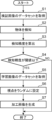
- FIG. 5 is a flowchart showing an example of processing of the image processing device 1 in the first embodiment.
- the acquisition unit 11 acquires a verification image dataset including a predetermined number of verification images from the verification image database 21.
- step S2 the detection unit 12 sequentially inputs each verification image forming the verification image data set to the learning model 22, thereby detecting an object included in the verification image.
- step S3 the verification unit 13 calculates the above-mentioned correct answer rate from the process of comparing the object detection result in the learning model 22 with the correct label for the dataset of the detected images acquired in step S1, and calculates The correct answer rate is calculated as the detection accuracy of the learning model 22.
- the verification unit 13 determines whether the detection accuracy calculated in step S3 is less than or equal to a threshold value (step S4). If the detection accuracy is determined to be less than or equal to the threshold (YES in step S4), the processing unit 14 acquires a learning image dataset including a predetermined number of learning images from the learning image database 23 (step S5).
- the processing unit 14 randomly sets the viewpoint for each learning image (step S6). Specifically, as described above, the viewpoints are randomly set by randomly setting the rotation angles ⁇ r, ⁇ p, and ⁇ y.
- the processing unit 14 generates a processed image in which the default viewpoint is changed to the set viewpoint by performing viewpoint conversion processing on each learning image (step S7).
- the generated processed image is stored in the learning image database 23.
- the processing unit 14 may generate K processed images by randomly setting K (K is an integer of 2 or more) viewpoints for one learning image.
- K is an integer of 2 or more
- a plurality of processed images in which objects are represented with various distortions are generated from one learning image.
- processed images suitable for learning by the learning model 22 can be efficiently generated.
- FIG. 6 is a flowchart illustrating an example of processing in the learning phase in the image processing device 1.
- step S21 the learning unit 16 acquires a processed image dataset including a predetermined number of processed images from the learning image database 23.
- step S22 the learning unit 16 causes the learning model 22 to learn by sequentially inputting the dataset of processed images to the learning model 22.
- step S23 the learning unit 16 performs object detection by comparing the object detection results in the learning model 22 and the correct label attached to the processed images for all processed images acquired in step S22.
- the correct answer rate is calculated, and the calculated correct answer rate is calculated as the detection accuracy of the learning model 22.
- the method of calculating the detection accuracy in the learning section 16 is the same as the method used in the verification section 13. That is, the learning unit 16 calculates, as the detection accuracy, a ratio in which the denominator is the total number of learning image data sets acquired in step S5 and the numerator is the number of learning images in which object detection has been successfully performed.
- step S24 the learning unit 16 determines whether the detection accuracy is greater than or equal to a threshold value.
- a threshold value an appropriate value such as 0.8 or 0.9 can be adopted. If the detection accuracy is equal to or greater than the threshold (YES in step S24), the process ends. On the other hand, if the detection accuracy is less than the threshold (NO in step S24), the process returns to step S21.
- the learning unit 16 may acquire the processed image data set from the learning image database 23 again and execute learning of the learning model 22.
- the dataset of processed images used may or may not include the same processed images as the processed images used for learning in the previous loop.
- the detection accuracy of the learning model 22 that detects the object from the verification image is calculated based on the correct label, and if the calculated detection accuracy is less than or equal to the threshold, the distortion of the object is large.
- the learning images are processed so that Thereby, it is possible to generate a learning image for generating a learning model that can accurately detect objects from omnidirectional images.
- the processing unit 14 shown in FIG. 1 uses the above-mentioned equations (1) and (2) to create an omnidirectional image (hereinafter referred to as the original image) before viewpoint conversion processing and a bounding box associated with the original image. Convert and onto the unit sphere. Conversion onto the unit sphere is performed using the above equations (1) and (2). Next, the processing unit 14 identifies two bounding boxes with the longest sections among the plurality of bounding boxes plotted on the unit sphere.
- P and Q be two points indicating the positions of two certain bounding boxes on the unit sphere.
- the center of gravity of the bounding box can be used as the position of the bounding box.
- the section refers to the longer arc of the two arcs delimited by the points P and Q in the great circle 301 passing through the points P and Q.
- the processing unit 14 identifies two bounding boxes with the longest sections, and sets the midpoint of the section between these two bounding boxes as a viewpoint.
- the processing unit 14 develops the original image on the unit sphere so that this viewpoint is located at the center of the equirectangular coordinate system.
- the objects corresponding to the two bounding boxes with the longest sections are located at the ends of the omnidirectional image where the distortion is large, resulting in an omnidirectional image in which the distortion of the object is increased.
- FIG. 7 is a diagram showing an image G40 to which the viewpoint conversion process in the second embodiment is applied.
- class labels such as window, chair, bathtub, light, mirror, and door are associated with bounding boxes.
- the section L between the position B1 of the bounding box E1 of the chair and the position B2 of the bounding box E2 of the door is determined to be the longest. Therefore, the original image was expanded so that the midpoint M1 of the section L became the viewpoint, and the image G40 was obtained.
- the chair and the door are displayed at both ends of the highly distorted image G40, and the distortion of the objects is increased.
- FIG. 8 is a flowchart showing an example of the processing of the image processing device 1 in the second embodiment.
- the processing in steps S31 to S35 is the same as the processing in steps S1 to S5 in FIG.
- the processing unit 14 identifies the longest section among the sections of any two bounding boxes among the plurality of bounding boxes associated with the learning image.
- step S37 the processing unit 14 sets the midpoint of the section as the viewpoint.
- step S38 a processed image is generated by expanding the learning image so that the set viewpoint is located at the center. As a result, a processed image in which the distortion of the object is increased compared to before the viewpoint conversion process is obtained.
- the learning image is processed so that the object to which the correct answer label is attached is displayed in a position where the distortion is large, so a processed image is generated in which the distortion of the object is expressed more greatly. can.
- processed images are generated so that more processed images including objects with easily distorted shapes are generated in omnidirectional images.
- the same components as in the first and second embodiments are given the same reference numerals, and the description thereof will be omitted. Further, a block diagram in the third embodiment will be explained using FIG. 1.
- FIG. 9 is a diagram showing an example of an object with a shape that is easily distorted.
- Objects with shapes that are easily distorted include objects whose aspect ratio exceeds the standard aspect ratio and objects whose size exceeds the standard size.
- the objects shown in images G91 and G92 are objects made of building materials whose aspect ratio exceeds the standard aspect ratio.
- Image G93 is an object made of construction material whose size is equal to or larger than the reference size. Examples of objects with shapes that are easily distorted include horizontal sofas, bathtubs, ceiling lights, and doors.
- the aspect ratio includes the ratio of the horizontal side to the vertical side of the bounding box attached to the object, and the ratio of the vertical side to the horizontal side.
- FIG. 10 is a flowchart showing an example of the processing of the image processing device 1 in the third embodiment. Steps S41 to S44 are the same as S1 to S4 in FIG. 5, so a description thereof will be omitted.
- step S45 the processing unit 14 acquires a learning image from the learning image database 23.
- step S46 the processing unit 14 calculates the size and aspect ratio of the object included in the learning image. For example, the processing unit 14 calculates the size of the object from the area of the bounding box associated with the learning image. The processing unit 14 calculates the aspect ratio from the lengths of the vertical and horizontal sides of the bounding box associated with the learning image.
- step S47 the processing unit 14 determines whether the learning image includes an object whose size is equal to or greater than the reference size or whose aspect ratio is equal to or greater than the reference aspect ratio. If the relevant object is included in the learning image (YES in step S47), the processing unit 14 randomly sets N (N is an integer of 2 or more) viewpoints for the learning image (step S48). .
- N is an integer of 2 or more
- the processing unit 14 may set N viewpoints using the method of the first embodiment. An example of N is 2.
- the processing unit 14 generates N processed images corresponding to the N viewpoints (step S49).
- the processing unit 14 may generate N processed images by executing a viewpoint conversion process so that the default viewpoint is changed to the set N viewpoints.
- the processing unit 14 processes the learning image by using M (M is equal to or greater than 1 and N is less than (a small integer) viewpoints are randomly set (step S50).
- M is equal to or greater than 1 and N is less than (a small integer) viewpoints are randomly set.
- An example of M is 1.
- the method of randomly setting viewpoints is the same as in the first embodiment.
- step S51 the processing unit 14 generates M processed images corresponding to M viewpoints.
- the processing unit 14 may generate M processed images by executing a viewpoint conversion process so that the default viewpoint is changed to the set M viewpoints.
- the processing unit 14 determines whether a predetermined number of learning images have been acquired from the learning image database 23 (step S52). If the predetermined number of learning images have been acquired (YES in step S52), the process ends. On the other hand, if the predetermined number of learning images have not been acquired (NO in step S52), the process returns to step S45, and the next learning image to be processed is acquired from the learning image database 23.
- the third embodiment when it is determined that an object with a shape that is easily distorted, such as a vertically long object, a horizontally long object, or a large object, is included in the learning image, the Since many processed images are generated, learning images that can improve the detection accuracy of such objects can be efficiently generated.
- FIG. 11 is a flowchart showing an example of processing of the image processing device 1 in the fourth embodiment. Since the processes in steps S71 and S72 are the same as steps S1 and S2 in FIG. 5, their explanation will be omitted.
- the verification unit 13 calculates object detection accuracy in each verification image for each object class. For example, if there are classes of objects to be detected such as a sofa, a ceiling light, and a door, the detection accuracy of each of the sofa, ceiling light, and door is calculated.
- step S74 the verification unit 13 determines whether there is an object that belongs to a class whose detection accuracy is equal to or less than a threshold value.
- a specific object an object belonging to a class whose detection accuracy is less than or equal to a threshold value will be referred to as a specific object. If it is determined that there is a specific object (YES in step S74), the processing unit 14 acquires a learning image dataset including a predetermined number of learning images including the specific object from the learning image database 23 (step S75). On the other hand, if it is determined that there is no specific object (NO in step S74), the process ends.
- step S76 the processing unit 14 sets a viewpoint for the learning image.
- the processing unit 14 may randomly set the viewpoint as shown in the first embodiment, or may set the midpoint of the longest section as the viewpoint as shown in the second embodiment.
- step S77 the processing unit 14 generates a processed image by applying viewpoint conversion processing to each learning image so that the default viewpoint becomes the set viewpoint (step S77).
- the processing unit 14 may generate a processed image by applying the viewpoint conversion processing described in Embodiment 1 or Embodiment 2.
- a learning image that includes an object that the learning model is not good at detecting is generated, so the learning model can be trained to increase the detection accuracy of the object.
- FIG. 12 is a block diagram showing an example of the configuration of the image processing device 1A in the fifth embodiment.
- a candidate image database 31 is stored in the memory 20 instead of the verification image database 21, and that the processor 10 is In other words, it includes a detection section 12A, a verification section 13A, and a processing section 14A.
- the candidate image database 31 stores candidate images that are learning candidates for the learning model 22. Like the verification image, the candidate image is an omnidirectional image associated with a correct label.
- the detection unit 12A detects objects from the candidate images by applying rule-based object detection processing to the candidate images acquired by the acquisition unit 11.
- Rule-based object detection processing corresponds to processing that detects objects from images without using a learning model obtained by machine learning. Examples of rule-based object detection processing include pattern matching, processing for detecting objects from the shape of edges included in edge-detected images, and the like. Note that the class of the object to be detected is determined in advance. Therefore, the template used for pattern matching is a template corresponding to the class of the object to be detected.
- the detection unit 12A calculates the degree of similarity for each class by applying a template for each class to the candidate image.
- the verification unit 13A calculates the similarity calculated by the detection unit 12A as the detection accuracy of the object detection process, and determines whether the detection accuracy is less than a threshold value. Note that the verification unit 13A may determine that the detection accuracy is below the threshold when the similarity of all classes is below the threshold.
- the processing unit 14A processes the candidate image so that the distortion of the object included in the candidate image becomes large.
- the output unit 15 stores the processed image processed by the processing unit 14A in the learning image database 23. This allows the learning model 22 to learn the processed image obtained by processing the candidate image.
- FIG. 13 is a flowchart illustrating an example of processing by the image processing apparatus 1A in the fifth embodiment.
- the acquisition unit 11 acquires a dataset of candidate images from the candidate image database 31.
- the detection unit 12A detects an object from the candidate images by applying rule-based object detection processing to each candidate image included in the acquired candidate image dataset (step S102).
- step S103 the verification unit 13A calculates the degree of similarity calculated when the detection unit 12A detects the object as detection accuracy.
- step S104 the verification unit 13A determines whether the detection accuracy is less than or equal to a threshold value. If the detection accuracy is less than or equal to the threshold (YES in step S104), the processing unit 14A sets a viewpoint on the candidate image (step S105). For example, the processing unit 14A may randomly set the viewpoint as shown in the first embodiment, or may set the midpoint of the longest section as the viewpoint as shown in the second embodiment. If the detection accuracy is greater than the threshold (NO in step S104), the process ends.
- step S106 the processing unit 14A generates a processed image by applying viewpoint conversion processing to the candidate image so that the default viewpoint becomes the set viewpoint (step S106).
- the processing unit 14A may generate a processed image by applying the viewpoint conversion processing described in Embodiment 1 or Embodiment 2.
- the processed image is stored in the learning image database 23.
- candidate images determined to have low object detection accuracy through rule-based object detection processing are processed, so it is possible to generate processed images for learning that include such objects.
- the omnidirectional image to be processed is a learning image stored in the learning image database 23, but it may also be a verification image.
- Embodiments 1 to 3 The aspect of acquiring a learning image including a specific object from the learning image database 23 shown in Embodiment 4 may be applied to Embodiments 1 to 3.
- a construction site is exemplified as a site, but the present disclosure is not limited to this, and includes a manufacturing site, a logistics site, a distribution site, farmland, a civil engineering site, a retail site, an office, a hospital, a commercial facility, A nursing home or the like may also be employed as a site.
- the present disclosure is useful in the technical field of detecting objects from omnidirectional images.
Landscapes
- Engineering & Computer Science (AREA)
- Theoretical Computer Science (AREA)
- Physics & Mathematics (AREA)
- General Physics & Mathematics (AREA)
- Multimedia (AREA)
- Computer Vision & Pattern Recognition (AREA)
- Artificial Intelligence (AREA)
- Health & Medical Sciences (AREA)
- Computing Systems (AREA)
- Databases & Information Systems (AREA)
- Evolutionary Computation (AREA)
- General Health & Medical Sciences (AREA)
- Medical Informatics (AREA)
- Software Systems (AREA)
- Image Analysis (AREA)
Priority Applications (3)
| Application Number | Priority Date | Filing Date | Title |
|---|---|---|---|
| CN202380048207.3A CN119422161A (zh) | 2022-06-21 | 2023-06-19 | 图像加工方法、图像加工装置以及图像加工程序 |
| JP2024528998A JPWO2023248968A1 (https=) | 2022-06-21 | 2023-06-19 | |
| US18/985,544 US20250118049A1 (en) | 2022-06-21 | 2024-12-18 | Image processing method, image processing device, and non-transitory computer readable recording medium |
Applications Claiming Priority (4)
| Application Number | Priority Date | Filing Date | Title |
|---|---|---|---|
| US202263354008P | 2022-06-21 | 2022-06-21 | |
| US63/354,008 | 2022-06-21 | ||
| JP2023073580 | 2023-04-27 | ||
| JP2023-073580 | 2023-04-27 |
Related Child Applications (1)
| Application Number | Title | Priority Date | Filing Date |
|---|---|---|---|
| US18/985,544 Continuation US20250118049A1 (en) | 2022-06-21 | 2024-12-18 | Image processing method, image processing device, and non-transitory computer readable recording medium |
Publications (1)
| Publication Number | Publication Date |
|---|---|
| WO2023248968A1 true WO2023248968A1 (ja) | 2023-12-28 |
Family
ID=89380007
Family Applications (1)
| Application Number | Title | Priority Date | Filing Date |
|---|---|---|---|
| PCT/JP2023/022533 Ceased WO2023248968A1 (ja) | 2022-06-21 | 2023-06-19 | 画像加工方法、画像加工装置、及び画像加工プログラム |
Country Status (4)
| Country | Link |
|---|---|
| US (1) | US20250118049A1 (https=) |
| JP (1) | JPWO2023248968A1 (https=) |
| CN (1) | CN119422161A (https=) |
| WO (1) | WO2023248968A1 (https=) |
Cited By (1)
| Publication number | Priority date | Publication date | Assignee | Title |
|---|---|---|---|---|
| JP7801832B1 (ja) * | 2025-09-09 | 2026-01-19 | スパーブエーアイ カンパニー リミテッド | 第1オブジェクトディテクションモデルの予測結果に基づいて決定された脆弱データに対して第2オブジェクトディテクションモデルの性能を評価する方法及びこれを利用したコンピューティング装置 |
Citations (3)
| Publication number | Priority date | Publication date | Assignee | Title |
|---|---|---|---|---|
| JP2020000678A (ja) * | 2018-06-29 | 2020-01-09 | 株式会社ニデック | 眼科画像処理装置、oct装置、眼科画像処理プログラム、および、数学モデル構築方法 |
| WO2020040061A1 (ja) * | 2018-08-24 | 2020-02-27 | ソニー株式会社 | 画像処理装置、画像処理方法及び画像処理プログラム |
| WO2022064632A1 (ja) * | 2020-09-25 | 2022-03-31 | 日本電気株式会社 | 画像処理装置、画像処理方法及びプログラム |
-
2023
- 2023-06-19 JP JP2024528998A patent/JPWO2023248968A1/ja active Pending
- 2023-06-19 CN CN202380048207.3A patent/CN119422161A/zh active Pending
- 2023-06-19 WO PCT/JP2023/022533 patent/WO2023248968A1/ja not_active Ceased
-
2024
- 2024-12-18 US US18/985,544 patent/US20250118049A1/en active Pending
Patent Citations (3)
| Publication number | Priority date | Publication date | Assignee | Title |
|---|---|---|---|---|
| JP2020000678A (ja) * | 2018-06-29 | 2020-01-09 | 株式会社ニデック | 眼科画像処理装置、oct装置、眼科画像処理プログラム、および、数学モデル構築方法 |
| WO2020040061A1 (ja) * | 2018-08-24 | 2020-02-27 | ソニー株式会社 | 画像処理装置、画像処理方法及び画像処理プログラム |
| WO2022064632A1 (ja) * | 2020-09-25 | 2022-03-31 | 日本電気株式会社 | 画像処理装置、画像処理方法及びプログラム |
Cited By (1)
| Publication number | Priority date | Publication date | Assignee | Title |
|---|---|---|---|---|
| JP7801832B1 (ja) * | 2025-09-09 | 2026-01-19 | スパーブエーアイ カンパニー リミテッド | 第1オブジェクトディテクションモデルの予測結果に基づいて決定された脆弱データに対して第2オブジェクトディテクションモデルの性能を評価する方法及びこれを利用したコンピューティング装置 |
Also Published As
| Publication number | Publication date |
|---|---|
| CN119422161A (zh) | 2025-02-11 |
| US20250118049A1 (en) | 2025-04-10 |
| JPWO2023248968A1 (https=) | 2023-12-28 |
Similar Documents
| Publication | Publication Date | Title |
|---|---|---|
| US12164839B2 (en) | Systems and methods for improved parametric modeling of structures | |
| JP5018721B2 (ja) | 立体模型の作製装置 | |
| CN108648194B (zh) | 基于cad模型三维目标识别分割和位姿测量方法及装置 | |
| JP4153761B2 (ja) | 3次元モデル空間生成装置、3次元モデル空間生成方法、及び3次元モデル空間生成プログラム | |
| CN112733641B (zh) | 物体尺寸测量方法、装置、设备及存储介质 | |
| JPWO2017203709A1 (ja) | 3次元モデル生成システム、3次元モデル生成方法、及びプログラム | |
| JP7585624B2 (ja) | 検出装置、検出方法及び検出プログラム | |
| JP7424573B2 (ja) | 三次元点群データに基づく三次元モデル生成装置 | |
| CN112507848B (zh) | 一种移动端实时人脸姿态估计方法 | |
| JPWO2006049147A1 (ja) | 三次元形状推定システム及び画像生成システム | |
| JP2023109570A (ja) | 情報処理装置、学習装置、画像認識装置、情報処理方法、学習方法、画像認識方法 | |
| Ozbay et al. | A hybrid method for skeleton extraction on Kinect sensor data: Combination of L1-Median and Laplacian shrinking algorithms | |
| WO2024198747A1 (zh) | 动作捕捉数据的处理方法、装置、设备及存储介质 | |
| WO2023248968A1 (ja) | 画像加工方法、画像加工装置、及び画像加工プログラム | |
| CN118071822A (zh) | 图像处理方法、装置、破拆机器人和计算机可读存储介质 | |
| CN114463617B (zh) | 锚护钢带安装孔的识别装置、方法、设备、介质及产品 | |
| CN116977511A (zh) | 运动数据处理方法、装置、产品、设备和介质 | |
| WO2022176104A1 (ja) | 推定装置、推定方法及び記憶媒体 | |
| JP2009048305A (ja) | 形状解析プログラム及び形状解析装置 | |
| CN116597001A (zh) | 室内顶部边界位置检测方法、装置、机器人及存储介质 | |
| JP2004252815A (ja) | 画像表示装置、画像表示方法およびプログラム | |
| JP4623320B2 (ja) | 三次元形状推定システム及び画像生成システム | |
| CN110134236B (zh) | 基于Unity3D和Kinect的低动作检测精度下的高交互反馈方法及系统 | |
| Wallbaum et al. | Towards real-time Scan-versus-BIM: Methods applications and challenges | |
| JP3894420B2 (ja) | 3次元モデル生成方法および装置 |
Legal Events
| Date | Code | Title | Description |
|---|---|---|---|
| 121 | Ep: the epo has been informed by wipo that ep was designated in this application |
Ref document number: 23827151 Country of ref document: EP Kind code of ref document: A1 |
|
| WWE | Wipo information: entry into national phase |
Ref document number: 2024528998 Country of ref document: JP |
|
| WWE | Wipo information: entry into national phase |
Ref document number: 202380048207.3 Country of ref document: CN |
|
| NENP | Non-entry into the national phase |
Ref country code: DE |
|
| WWP | Wipo information: published in national office |
Ref document number: 202380048207.3 Country of ref document: CN |
|
| 122 | Ep: pct application non-entry in european phase |
Ref document number: 23827151 Country of ref document: EP Kind code of ref document: A1 |