WO2023248968A1 - Image processing method, image processing device, and image processing program - Google Patents
Image processing method, image processing device, and image processing program Download PDFInfo
- Publication number
- WO2023248968A1 WO2023248968A1 PCT/JP2023/022533 JP2023022533W WO2023248968A1 WO 2023248968 A1 WO2023248968 A1 WO 2023248968A1 JP 2023022533 W JP2023022533 W JP 2023022533W WO 2023248968 A1 WO2023248968 A1 WO 2023248968A1
- Authority
- WO
- WIPO (PCT)
- Prior art keywords
- image
- processing
- learning
- detection accuracy
- image processing
- Prior art date
Links
- 238000012545 processing Methods 0.000 title claims abstract description 168
- 238000003672 processing method Methods 0.000 title claims description 27
- 238000001514 detection method Methods 0.000 claims abstract description 130
- 238000000034 method Methods 0.000 claims abstract description 51
- 238000006243 chemical reaction Methods 0.000 claims description 29
- 230000027455 binding Effects 0.000 claims description 2
- 238000009739 binding Methods 0.000 claims description 2
- 238000012795 verification Methods 0.000 description 46
- 238000010586 diagram Methods 0.000 description 17
- 238000010276 construction Methods 0.000 description 13
- 238000010801 machine learning Methods 0.000 description 4
- 239000000470 constituent Substances 0.000 description 3
- 238000004891 communication Methods 0.000 description 2
- 230000010365 information processing Effects 0.000 description 2
- 230000009466 transformation Effects 0.000 description 2
- 238000013528 artificial neural network Methods 0.000 description 1
- 239000004566 building material Substances 0.000 description 1
- 238000004590 computer program Methods 0.000 description 1
- 238000012790 confirmation Methods 0.000 description 1
- 239000004035 construction material Substances 0.000 description 1
- 238000013527 convolutional neural network Methods 0.000 description 1
- 238000009826 distribution Methods 0.000 description 1
- 238000005516 engineering process Methods 0.000 description 1
- 230000005484 gravity Effects 0.000 description 1
- 238000004519 manufacturing process Methods 0.000 description 1
- 238000012986 modification Methods 0.000 description 1
- 230000004048 modification Effects 0.000 description 1
- 230000000474 nursing effect Effects 0.000 description 1
- 239000007787 solid Substances 0.000 description 1
- 238000003860 storage Methods 0.000 description 1
- 238000012549 training Methods 0.000 description 1
Images


Classifications
-
- G—PHYSICS
- G06—COMPUTING; CALCULATING OR COUNTING
- G06T—IMAGE DATA PROCESSING OR GENERATION, IN GENERAL
- G06T3/00—Geometric image transformation in the plane of the image
-
- G—PHYSICS
- G06—COMPUTING; CALCULATING OR COUNTING
- G06T—IMAGE DATA PROCESSING OR GENERATION, IN GENERAL
- G06T7/00—Image analysis
Definitions
- the present disclosure relates to a technique for processing images.
- Patent Document 1 discloses that a region in which an object is likely to exist is selected from a camera image taken by an omnidirectional camera, and the candidate region is A technique has been disclosed that rotates the orientation of a region and performs object detection processing on the rotated candidate region.
- Patent Document 1 is a technique for rotating the orientation of a candidate area so that the distortion of an object included in the candidate area is reduced, and is not a technique for deliberately increasing the distortion of an object on an image. Therefore, Patent Document 1 cannot generate a learning image for accurately detecting an object from a distorted image.
- the present disclosure is intended to solve such problems, and aims to provide a technique for generating a learning image that can accurately detect an object from a distorted image.
- An image processing method is an image processing method in a computer, which acquires an image composed of omnidirectional images, performs object detection processing to detect an object from the acquired image, and The detection accuracy of the object in the detection process is calculated, the image is processed based on the detection accuracy so that the distortion of the object included in the image becomes large, and the processed processed image is output.
- FIG. 1 is a block diagram illustrating an example of the configuration of an image processing device according to an embodiment of the present disclosure.
- FIG. 3 is a diagram showing how viewpoint conversion processing is executed.
- FIG. 3 is an explanatory diagram of viewpoint conversion processing.
- FIG. 3 is a diagram showing a display screen of a user interface to which an image to which object detection processing has been performed using a learning model is applied.
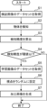
- 5 is a flowchart illustrating an example of processing of the image processing apparatus in the first embodiment.
- 3 is a flowchart illustrating an example of processing in a learning phase in the image processing device 1.
- FIG. FIG. 7 is a diagram showing an image to which viewpoint conversion processing in Embodiment 2 is applied. 7 is a flowchart illustrating an example of processing by the image processing device in Embodiment 2.
- FIG. FIG. 2 is a diagram showing an example of an object having a shape that is easily distorted.
- 7 is a flowchart illustrating an example of processing of the image processing apparatus in Embodiment 3.
- 12 is a flowchart illustrating an example of processing by the image processing apparatus in Embodiment 4.
- 12 is a block diagram showing an example of the configuration of an image processing device in Embodiment 5.
- FIG. 12 is a flowchart illustrating an example of processing of the image processing apparatus 1A in Embodiment 5.
- Issues at construction sites include communication issues such as not being able to convey specific instructions to workers, the time it takes to explain those instructions, the need for manpower to go around the entire construction site, and the time it takes to travel to the construction site. There are challenges in confirming construction sites, such as this.
- an omnidirectional image in which object detection has been performed using a learning model is displayed on the display, and when the user inputs an operation to select an object on the display, the bounding set for that object is displayed.
- a possible mode is to display a box as an annotation area.
- the user can display the default frame on the omnidirectional image, position the frame on the target object, and annotate the frame without inputting operations to transform the frame to fit the object.
- the area can be set, reducing the user's effort.
- the inventor of the present invention proposed that by generating an image in which the object is more distorted as a learning image and training the learning model with that image, the learning model can accurately detect the object from such an image. After obtaining the knowledge that a model can be generated, each aspect of the present disclosure was conceived.
- An image processing method in one aspect of the present disclosure is an image processing method in a computer, which acquires an image composed of omnidirectional images and executes object detection processing to detect an object from the acquired image. , calculating the detection accuracy of the object in the object detection process, processing the image so that the distortion of the object included in the image is increased based on the detection accuracy, and outputting the processed processed image. .
- the detection accuracy when object detection processing is performed on the image is calculated, and based on the calculated detection accuracy, the image is processed so that the distortion of the object becomes large.
- the image is an image composed of omnidirectional images associated with correct labels of objects, and the detection accuracy is calculated based on the correct labels.
- the processing may be performed when the detection accuracy is below a threshold.
- the image includes a first image and a second image different from the first image, and the detection accuracy is determined by the object detection process executed. This is the detection accuracy with respect to a detection result when the first image is input to a learning model trained in advance to perform the processing, and the processing of the image may be performed on the second image.
- the learning model may be further trained using the processed image.
- the learning model is trained using an image in which the object has a large distortion, it is possible to generate a learning model that can accurately detect the object from the distorted image.
- the detection accuracy is calculated for each class of object, and the second image is based on the detection accuracy in the first image.
- the image may include an object determined to be less than or equal to a threshold value.
- the learning model can be trained to increase the detection accuracy of the object.
- the image processing may include changing a default viewpoint of the image to a randomly set viewpoint. good.
- the image is processed by randomly changing the viewpoint, so objects that were displayed in a position with little distortion before processing are more likely to be displayed in a position with large distortion, and can generate images with larger distortions.
- the image processing is performed using two bindings having the longest distance among a plurality of correct labels set for the image.
- the method may include identifying a section of a box and setting a viewpoint of the image at a midpoint of the section.
- the image is processed so that the object to which the correct label is attached is displayed at the edge of the image, so it is possible to generate an image in which the object is more distorted.
- the image processing is performed to determine whether or not the image contains an object whose aspect ratio and size exceed a reference value. and increasing the number of processed images when it is determined that an object exceeding the reference value is included, compared to when it is determined that the object is not included; May include.
- the object detection processing is rule-based object detection processing, and the image processing is performed on the image on which the object detection processing has been performed. It may also include doing so.
- the image processing is performed by performing viewpoint conversion processing to increase the distortion of the object.
- the viewpoint conversion process includes projecting the image onto a unit spherical surface, setting a new viewpoint from the projected projection image, and converting the image so that the new viewpoint becomes the center.
- the method may also include developing the projected image onto a plane.
- An image processing device is an image processing device including a processor, wherein the processor acquires an image composed of omnidirectional images, and detects an object from the acquired image. perform object detection processing to calculate the detection accuracy of the object in the object detection processing, process the image so that distortion of the object included in the image becomes large based on the detection accuracy, and perform the processing. Output the processed image and execute the processing.
- An image processing program causes a computer to execute the image processing method described in any one of (1) to (10) above.
- the present disclosure can also be realized as an information processing system operated by such an information processing program. Further, it goes without saying that such a computer program can be distributed via a computer-readable non-transitory recording medium such as a CD-ROM or a communication network such as the Internet.
- a computer-readable non-transitory recording medium such as a CD-ROM or a communication network such as the Internet.
- FIG. 1 is a block diagram showing an example of the configuration of an image processing device 1 according to an embodiment of the present disclosure.
- the image processing device 1 is a computer including a processor 10 and a memory 20.
- the processor 10 is, for example, a central processing unit (CPU).
- the processor 10 includes an acquisition section 11 , a detection section 12 , a verification section 13 , a processing section 14 , an output section 15 , and a learning section 16 .
- the acquisition unit 11 to learning unit 16 are realized by the processor 10 executing an image processing program.
- the memory 20 is composed of a nonvolatile rewritable storage device such as a solid state drive (SSD).
- SSD solid state drive
- Memory 20 includes a verification image database 21, a learning model 22, and a learning image database 23.
- all blocks are integrated into one computer, but they may be distributed and arranged among multiple computers.
- the plurality of computers are connected to be able to communicate with each other via the Internet or a local area network.
- the learning section 16 may be installed in a device different from the image processing device 1
- the memory 20 may be installed in a device different from the image processing device 1.
- the acquisition unit 11 acquires a verification image from the verification image database 21.
- the verification image is an image for verifying the object detection accuracy of the learning model 22.
- an omnidirectional image is employed as the verification image.
- the verification image is associated with the correct label of the object.
- the verification image is an example of the first image.
- the correct label includes a bounding box indicating the position of the object in the verification image and a class label indicating the class to which the object belongs.
- the omnidirectional image is an image captured by an omnidirectional camera. A normal camera can only take images within a certain angle, but an omnidirectional camera can take images in 360 degrees, that is, in all directions, up, down, left, right, front and back.
- the omnidirectional image is an image obtained by developing an image captured by an omnidirectional camera using a developing method such as equirectangular projection, the image has different distortions depending on the position. Therefore, when detecting an object from an omnidirectional image using a learning model trained using only images captured by a normal camera, there is a high possibility that object detection accuracy will decrease.
- the detection unit 12 executes object detection processing to detect an object from the verification image acquired by the acquisition unit 11. Specifically, the detection unit 12 inputs the verification image to the learning model 22 and obtains the detection result, thereby executing the object detection process.
- the learning model 22 is a model that has been subjected to machine learning in advance to execute object detection processing.
- the learning model 22 may be any model that can detect an object from an image, such as a deep neural network or a convolutional neural network.
- the learning model 22 is generated by machine learning a dataset of learning images to which correct labels of objects are assigned.
- the verification unit 13 calculates the object detection accuracy in the learning model 22 based on the correct label associated with the verification image, and determines whether the calculated detection accuracy is less than a threshold value.
- Detection accuracy is defined, for example, as a ratio where the denominator is the total number of objects included in the verification image used for verification and the numerator is the number of objects for which object detection was successful, that is, the accuracy rate.
- the verification unit 13 may determine that the object has been successfully detected if the class label of the object output as a detection result from the learning model 22 matches the class label included in the correct label. Alternatively, if the class label of the object output as a detection result from the learning model 22 matches the class label included in the correct label, and the reliability of the object exceeds the reference reliability, the verification unit 13 detects the object. may be determined to have been successful.
- the verification unit 13 may determine whether the reliability of each class exceeds the reference reliability. . Then, if the reliability exceeds the reference reliability in all classes, the verification unit 13 may determine that object detection has been successful.
- Class refers to the type of object.
- the processing unit 14 processes the image based on the detection accuracy so that the distortion of the object included in the image becomes large. Specifically, when the detection accuracy calculated by the verification unit 13 is less than the threshold value, the processing unit 14 processes the learning image so that the distortion of the object included in the verification image becomes large. More specifically, the processing unit 14 acquires a learning image from the learning image database 23 and executes a viewpoint conversion process to change the default viewpoint of the acquired learning image to a randomly set viewpoint. All you have to do is process it. Like the verification image, the learning image is an omnidirectional image, and is associated with the correct label of the object in advance. The learning image is an example of the second image. Therefore, the correct label is also inherited to the processed image obtained by processing the learning image.
- the default viewpoint is a viewpoint set as an initial value, and is, for example, a point parallel to the horizontal plane of the omnidirectional camera and corresponding to the north direction.
- the viewpoint is located at the center of the omnidirectional image.
- the output unit 15 stores the processed image processed by the processing unit 14 in the learning image database 23.
- the learning unit 16 trains the learning model 22 using the processed images stored in the learning image database 23.
- the learning unit 16 calculates a learning error based on the correct label given to the processed image and the reliability output from the learning model 22, and updates the parameters of the learning model 22 so that the learning error is minimized. do.
- a parameter updating method an error backpropagation method can be adopted.
- the parameters include weight values, bias values, and the like.
- the verification image database 21 stores verification images.
- the learning model 22 is a learning model 22 to be verified.
- the learning image database 23 stores learning images.
- FIG. 2 is a diagram showing how the viewpoint conversion process is executed.
- Image G10 is an omnidirectional image before viewpoint conversion processing
- image G20 is an omnidirectional image after viewpoint conversion processing.
- the viewpoint A1 is changed by 180 degrees in the horizontal direction with respect to the image G10.
- images G10 and G20 viewpoint A1 is located at the center of the images. Since images G10 and G20 are omnidirectional images, the distortion differs depending on the position. For example, it can be seen that the distortion is larger in the left and right end areas and in the upper and lower end areas compared to the center area.
- Object F1 is the same object in image G10 and image G20.
- FIG. 3 is an explanatory diagram of viewpoint conversion processing.
- the image G30 is an omnidirectional image and is expressed in an equirectangular projection coordinate system.
- the coordinate system of the equirectangular projection (an example of a plane) is a two-dimensional coordinate system in which the horizontal direction is the u-axis and the vertical direction is the v-axis.
- the image G30 has a horizontal size of 2h and a vertical size of h.
- the processing unit 14 transforms the point Q in the image G30 into a polar coordinate system with a radius of 1.
- the point Q(u,v) is expressed by equation (1).
- the processing unit 14 projects the point Q from the polar coordinate system to the three-dimensional orthogonal coordinate system.
- the point Q (x, y, z) is expressed by equation (2).
- the processing unit 14 sets rotation matrices Y ( ⁇ y), P ( ⁇ p), and R ( ⁇ r) for the three axes of yaw, pitch, and roll.
- ⁇ y is the rotation angle around the yaw axis
- ⁇ p is the rotation angle around the pitch axis
- ⁇ r is the rotation angle around the roll axis.
- the point Q (x, y, z) is projected onto the point Q' (x', y', z') as shown in equation (3).
- the processing unit 14 converts the point Q' from the orthogonal coordinate system to the polar coordinate system using equation (4).
- ⁇ ' is the zenith angle after conversion
- ⁇ ' is the declination angle after conversion.
- the processing unit 14 converts the point Q' from the polar coordinate system to the equirectangular projection coordinate system.
- point Q' is expressed by equation (5).
- u' is the coordinate value of the u-axis after viewpoint transformation
- v' is the coordinate value of the v-axis after viewpoint transformation.
- the processing unit 14 randomly converts the viewpoint of the image G30 by randomly setting the rotation angles ⁇ r, ⁇ p, and ⁇ y. Specifically, the processing unit 14 sets the center of the image G30 in the equirectangular coordinate system rotated by the rotation angles ⁇ r, ⁇ p, and ⁇ y as the viewpoint. Note that in the embodiments described below, the processing unit 14 executes the viewpoint conversion process not randomly but using a method according to the embodiment.
- FIG. 4 is a diagram showing a display screen G1 of the user interface to which an image subjected to object detection processing by the learning model 22 is applied.
- the display screen G1 is the basic screen of the application for a remote user to check the situation at the work site.
- the display screen G1 includes an image display field R1, an annotation information display field R2, and a blueprint display field R3.
- a blueprint of the work site is displayed in the blueprint display field R3, and a selection icon 201, a photographing point icon 202, and a trajectory 203 are superimposed on this blueprint.
- a worker has previously carried out a photographing operation using an omnidirectional camera, and the photographing point icon 202 indicates the photographing point of the image taken during this photographing operation.
- a trajectory 203 indicates a trajectory of movement of the worker during the photographing work.
- the user inputs an operation to select one shooting location icon 202 by dragging and dropping the selection icon 201 on the blueprint. Then, an omnidirectional image of the work site photographed at the photographing point indicated by the selected one photographing point icon 202 is displayed in the image display column R1. The user sets an annotation area D1 on the image displayed in the image display field R1, and inputs an annotation message for this annotation area D1 into the annotation information display field R2. Thereby, the annotation area D1 and the annotation message are shared between users. As a result, remote users can check the latest status and precautions at the work site in detail without having to travel to the work site.
- the omnidirectional image displayed in the image display field R1 has been subjected to object detection processing in advance by the learning model 22. Therefore, when the user inputs an operation to select an object to which he or she wishes to annotate in this omnidirectional image, the bounding box of that object is displayed, and the annotation area D1 can be set based on this bounding box. As a result, the user displays a frame for setting the annotation area D1 in the image display field R1, moves the frame to the position of the target object, and deforms the frame to match the shape of the object.
- the annotation area D1 can be set without inputting any operation.
- FIG. 5 is a flowchart showing an example of processing of the image processing device 1 in the first embodiment.
- the acquisition unit 11 acquires a verification image dataset including a predetermined number of verification images from the verification image database 21.
- step S2 the detection unit 12 sequentially inputs each verification image forming the verification image data set to the learning model 22, thereby detecting an object included in the verification image.
- step S3 the verification unit 13 calculates the above-mentioned correct answer rate from the process of comparing the object detection result in the learning model 22 with the correct label for the dataset of the detected images acquired in step S1, and calculates The correct answer rate is calculated as the detection accuracy of the learning model 22.
- the verification unit 13 determines whether the detection accuracy calculated in step S3 is less than or equal to a threshold value (step S4). If the detection accuracy is determined to be less than or equal to the threshold (YES in step S4), the processing unit 14 acquires a learning image dataset including a predetermined number of learning images from the learning image database 23 (step S5).
- the processing unit 14 randomly sets the viewpoint for each learning image (step S6). Specifically, as described above, the viewpoints are randomly set by randomly setting the rotation angles ⁇ r, ⁇ p, and ⁇ y.
- the processing unit 14 generates a processed image in which the default viewpoint is changed to the set viewpoint by performing viewpoint conversion processing on each learning image (step S7).
- the generated processed image is stored in the learning image database 23.
- the processing unit 14 may generate K processed images by randomly setting K (K is an integer of 2 or more) viewpoints for one learning image.
- K is an integer of 2 or more
- a plurality of processed images in which objects are represented with various distortions are generated from one learning image.
- processed images suitable for learning by the learning model 22 can be efficiently generated.
- FIG. 6 is a flowchart illustrating an example of processing in the learning phase in the image processing device 1.
- step S21 the learning unit 16 acquires a processed image dataset including a predetermined number of processed images from the learning image database 23.
- step S22 the learning unit 16 causes the learning model 22 to learn by sequentially inputting the dataset of processed images to the learning model 22.
- step S23 the learning unit 16 performs object detection by comparing the object detection results in the learning model 22 and the correct label attached to the processed images for all processed images acquired in step S22.
- the correct answer rate is calculated, and the calculated correct answer rate is calculated as the detection accuracy of the learning model 22.
- the method of calculating the detection accuracy in the learning section 16 is the same as the method used in the verification section 13. That is, the learning unit 16 calculates, as the detection accuracy, a ratio in which the denominator is the total number of learning image data sets acquired in step S5 and the numerator is the number of learning images in which object detection has been successfully performed.
- step S24 the learning unit 16 determines whether the detection accuracy is greater than or equal to a threshold value.
- a threshold value an appropriate value such as 0.8 or 0.9 can be adopted. If the detection accuracy is equal to or greater than the threshold (YES in step S24), the process ends. On the other hand, if the detection accuracy is less than the threshold (NO in step S24), the process returns to step S21.
- the learning unit 16 may acquire the processed image data set from the learning image database 23 again and execute learning of the learning model 22.
- the dataset of processed images used may or may not include the same processed images as the processed images used for learning in the previous loop.
- the detection accuracy of the learning model 22 that detects the object from the verification image is calculated based on the correct label, and if the calculated detection accuracy is less than or equal to the threshold, the distortion of the object is large.
- the learning images are processed so that Thereby, it is possible to generate a learning image for generating a learning model that can accurately detect objects from omnidirectional images.
- the processing unit 14 shown in FIG. 1 uses the above-mentioned equations (1) and (2) to create an omnidirectional image (hereinafter referred to as the original image) before viewpoint conversion processing and a bounding box associated with the original image. Convert and onto the unit sphere. Conversion onto the unit sphere is performed using the above equations (1) and (2). Next, the processing unit 14 identifies two bounding boxes with the longest sections among the plurality of bounding boxes plotted on the unit sphere.
- P and Q be two points indicating the positions of two certain bounding boxes on the unit sphere.
- the center of gravity of the bounding box can be used as the position of the bounding box.
- the section refers to the longer arc of the two arcs delimited by the points P and Q in the great circle 301 passing through the points P and Q.
- the processing unit 14 identifies two bounding boxes with the longest sections, and sets the midpoint of the section between these two bounding boxes as a viewpoint.
- the processing unit 14 develops the original image on the unit sphere so that this viewpoint is located at the center of the equirectangular coordinate system.
- the objects corresponding to the two bounding boxes with the longest sections are located at the ends of the omnidirectional image where the distortion is large, resulting in an omnidirectional image in which the distortion of the object is increased.
- FIG. 7 is a diagram showing an image G40 to which the viewpoint conversion process in the second embodiment is applied.
- class labels such as window, chair, bathtub, light, mirror, and door are associated with bounding boxes.
- the section L between the position B1 of the bounding box E1 of the chair and the position B2 of the bounding box E2 of the door is determined to be the longest. Therefore, the original image was expanded so that the midpoint M1 of the section L became the viewpoint, and the image G40 was obtained.
- the chair and the door are displayed at both ends of the highly distorted image G40, and the distortion of the objects is increased.
- FIG. 8 is a flowchart showing an example of the processing of the image processing device 1 in the second embodiment.
- the processing in steps S31 to S35 is the same as the processing in steps S1 to S5 in FIG.
- the processing unit 14 identifies the longest section among the sections of any two bounding boxes among the plurality of bounding boxes associated with the learning image.
- step S37 the processing unit 14 sets the midpoint of the section as the viewpoint.
- step S38 a processed image is generated by expanding the learning image so that the set viewpoint is located at the center. As a result, a processed image in which the distortion of the object is increased compared to before the viewpoint conversion process is obtained.
- the learning image is processed so that the object to which the correct answer label is attached is displayed in a position where the distortion is large, so a processed image is generated in which the distortion of the object is expressed more greatly. can.
- processed images are generated so that more processed images including objects with easily distorted shapes are generated in omnidirectional images.
- the same components as in the first and second embodiments are given the same reference numerals, and the description thereof will be omitted. Further, a block diagram in the third embodiment will be explained using FIG. 1.
- FIG. 9 is a diagram showing an example of an object with a shape that is easily distorted.
- Objects with shapes that are easily distorted include objects whose aspect ratio exceeds the standard aspect ratio and objects whose size exceeds the standard size.
- the objects shown in images G91 and G92 are objects made of building materials whose aspect ratio exceeds the standard aspect ratio.
- Image G93 is an object made of construction material whose size is equal to or larger than the reference size. Examples of objects with shapes that are easily distorted include horizontal sofas, bathtubs, ceiling lights, and doors.
- the aspect ratio includes the ratio of the horizontal side to the vertical side of the bounding box attached to the object, and the ratio of the vertical side to the horizontal side.
- FIG. 10 is a flowchart showing an example of the processing of the image processing device 1 in the third embodiment. Steps S41 to S44 are the same as S1 to S4 in FIG. 5, so a description thereof will be omitted.
- step S45 the processing unit 14 acquires a learning image from the learning image database 23.
- step S46 the processing unit 14 calculates the size and aspect ratio of the object included in the learning image. For example, the processing unit 14 calculates the size of the object from the area of the bounding box associated with the learning image. The processing unit 14 calculates the aspect ratio from the lengths of the vertical and horizontal sides of the bounding box associated with the learning image.
- step S47 the processing unit 14 determines whether the learning image includes an object whose size is equal to or greater than the reference size or whose aspect ratio is equal to or greater than the reference aspect ratio. If the relevant object is included in the learning image (YES in step S47), the processing unit 14 randomly sets N (N is an integer of 2 or more) viewpoints for the learning image (step S48). .
- N is an integer of 2 or more
- the processing unit 14 may set N viewpoints using the method of the first embodiment. An example of N is 2.
- the processing unit 14 generates N processed images corresponding to the N viewpoints (step S49).
- the processing unit 14 may generate N processed images by executing a viewpoint conversion process so that the default viewpoint is changed to the set N viewpoints.
- the processing unit 14 processes the learning image by using M (M is equal to or greater than 1 and N is less than (a small integer) viewpoints are randomly set (step S50).
- M is equal to or greater than 1 and N is less than (a small integer) viewpoints are randomly set.
- An example of M is 1.
- the method of randomly setting viewpoints is the same as in the first embodiment.
- step S51 the processing unit 14 generates M processed images corresponding to M viewpoints.
- the processing unit 14 may generate M processed images by executing a viewpoint conversion process so that the default viewpoint is changed to the set M viewpoints.
- the processing unit 14 determines whether a predetermined number of learning images have been acquired from the learning image database 23 (step S52). If the predetermined number of learning images have been acquired (YES in step S52), the process ends. On the other hand, if the predetermined number of learning images have not been acquired (NO in step S52), the process returns to step S45, and the next learning image to be processed is acquired from the learning image database 23.
- the third embodiment when it is determined that an object with a shape that is easily distorted, such as a vertically long object, a horizontally long object, or a large object, is included in the learning image, the Since many processed images are generated, learning images that can improve the detection accuracy of such objects can be efficiently generated.
- FIG. 11 is a flowchart showing an example of processing of the image processing device 1 in the fourth embodiment. Since the processes in steps S71 and S72 are the same as steps S1 and S2 in FIG. 5, their explanation will be omitted.
- the verification unit 13 calculates object detection accuracy in each verification image for each object class. For example, if there are classes of objects to be detected such as a sofa, a ceiling light, and a door, the detection accuracy of each of the sofa, ceiling light, and door is calculated.
- step S74 the verification unit 13 determines whether there is an object that belongs to a class whose detection accuracy is equal to or less than a threshold value.
- a specific object an object belonging to a class whose detection accuracy is less than or equal to a threshold value will be referred to as a specific object. If it is determined that there is a specific object (YES in step S74), the processing unit 14 acquires a learning image dataset including a predetermined number of learning images including the specific object from the learning image database 23 (step S75). On the other hand, if it is determined that there is no specific object (NO in step S74), the process ends.
- step S76 the processing unit 14 sets a viewpoint for the learning image.
- the processing unit 14 may randomly set the viewpoint as shown in the first embodiment, or may set the midpoint of the longest section as the viewpoint as shown in the second embodiment.
- step S77 the processing unit 14 generates a processed image by applying viewpoint conversion processing to each learning image so that the default viewpoint becomes the set viewpoint (step S77).
- the processing unit 14 may generate a processed image by applying the viewpoint conversion processing described in Embodiment 1 or Embodiment 2.
- a learning image that includes an object that the learning model is not good at detecting is generated, so the learning model can be trained to increase the detection accuracy of the object.
- FIG. 12 is a block diagram showing an example of the configuration of the image processing device 1A in the fifth embodiment.
- a candidate image database 31 is stored in the memory 20 instead of the verification image database 21, and that the processor 10 is In other words, it includes a detection section 12A, a verification section 13A, and a processing section 14A.
- the candidate image database 31 stores candidate images that are learning candidates for the learning model 22. Like the verification image, the candidate image is an omnidirectional image associated with a correct label.
- the detection unit 12A detects objects from the candidate images by applying rule-based object detection processing to the candidate images acquired by the acquisition unit 11.
- Rule-based object detection processing corresponds to processing that detects objects from images without using a learning model obtained by machine learning. Examples of rule-based object detection processing include pattern matching, processing for detecting objects from the shape of edges included in edge-detected images, and the like. Note that the class of the object to be detected is determined in advance. Therefore, the template used for pattern matching is a template corresponding to the class of the object to be detected.
- the detection unit 12A calculates the degree of similarity for each class by applying a template for each class to the candidate image.
- the verification unit 13A calculates the similarity calculated by the detection unit 12A as the detection accuracy of the object detection process, and determines whether the detection accuracy is less than a threshold value. Note that the verification unit 13A may determine that the detection accuracy is below the threshold when the similarity of all classes is below the threshold.
- the processing unit 14A processes the candidate image so that the distortion of the object included in the candidate image becomes large.
- the output unit 15 stores the processed image processed by the processing unit 14A in the learning image database 23. This allows the learning model 22 to learn the processed image obtained by processing the candidate image.
- FIG. 13 is a flowchart illustrating an example of processing by the image processing apparatus 1A in the fifth embodiment.
- the acquisition unit 11 acquires a dataset of candidate images from the candidate image database 31.
- the detection unit 12A detects an object from the candidate images by applying rule-based object detection processing to each candidate image included in the acquired candidate image dataset (step S102).
- step S103 the verification unit 13A calculates the degree of similarity calculated when the detection unit 12A detects the object as detection accuracy.
- step S104 the verification unit 13A determines whether the detection accuracy is less than or equal to a threshold value. If the detection accuracy is less than or equal to the threshold (YES in step S104), the processing unit 14A sets a viewpoint on the candidate image (step S105). For example, the processing unit 14A may randomly set the viewpoint as shown in the first embodiment, or may set the midpoint of the longest section as the viewpoint as shown in the second embodiment. If the detection accuracy is greater than the threshold (NO in step S104), the process ends.
- step S106 the processing unit 14A generates a processed image by applying viewpoint conversion processing to the candidate image so that the default viewpoint becomes the set viewpoint (step S106).
- the processing unit 14A may generate a processed image by applying the viewpoint conversion processing described in Embodiment 1 or Embodiment 2.
- the processed image is stored in the learning image database 23.
- candidate images determined to have low object detection accuracy through rule-based object detection processing are processed, so it is possible to generate processed images for learning that include such objects.
- the omnidirectional image to be processed is a learning image stored in the learning image database 23, but it may also be a verification image.
- Embodiments 1 to 3 The aspect of acquiring a learning image including a specific object from the learning image database 23 shown in Embodiment 4 may be applied to Embodiments 1 to 3.
- a construction site is exemplified as a site, but the present disclosure is not limited to this, and includes a manufacturing site, a logistics site, a distribution site, farmland, a civil engineering site, a retail site, an office, a hospital, a commercial facility, A nursing home or the like may also be employed as a site.
- the present disclosure is useful in the technical field of detecting objects from omnidirectional images.
Abstract
An image processing device according to the present invention acquires images constituted from omnidirectional images having associated therewith correct labels for objects, executes object detection processing for detecting the objects from the acquired images, calculates the accuracy of object detection in the object detection processing on the basis of the correct labels, and processes the images so as to increase distortions of the objects included in the images when the detection accuracy is less than a threshold.
Description
本開示は、画像を加工する技術に関するものである。
The present disclosure relates to a technique for processing images.
特許文献1には、全方位カメラにより撮影されたカメラ映像から物体が存在する可能性が高い領域を候補領域として選択して、選択した候補領域に含まれる物体が鉛直方向を向くように、候補領域の向きを回転し、回転後の候補領域に対して物体検知処理を実行する技術が開示されている。
Patent Document 1 discloses that a region in which an object is likely to exist is selected from a camera image taken by an omnidirectional camera, and the candidate region is A technique has been disclosed that rotates the orientation of a region and performs object detection processing on the rotated candidate region.
しかしながら、特許文献1は、候補領域に含まれる物体の歪が少なくなるように候補領域の向きを回転する技術であり、画像上の物体の歪をあえて増大させる技術ではない。したがって、特許文献1は、歪を有する画像から物体を精度よく検知するための学習用の画像を生成することはできない。
However, Patent Document 1 is a technique for rotating the orientation of a candidate area so that the distortion of an object included in the candidate area is reduced, and is not a technique for deliberately increasing the distortion of an object on an image. Therefore, Patent Document 1 cannot generate a learning image for accurately detecting an object from a distorted image.
本開示は、このような課題を解決するためのものであり、歪を有する画像から物体を精度よく検知し得る学習用の画像を生成する技術を提供することを目的とする。
The present disclosure is intended to solve such problems, and aims to provide a technique for generating a learning image that can accurately detect an object from a distorted image.
本開示の一態様における画像加工方法は、コンピュータにおける画像加工方法であって、全方位画像で構成される画像を取得し、取得した前記画像から物体を検知する物体検知処理を実行し、前記物体検知処理における前記物体の検知精度を算出し、前記検知精度に基づいて、前記画像に含まれる物体の歪が大きくなるように前記画像を加工し、前記加工された加工画像を出力する。
An image processing method according to an aspect of the present disclosure is an image processing method in a computer, which acquires an image composed of omnidirectional images, performs object detection processing to detect an object from the acquired image, and The detection accuracy of the object in the detection process is calculated, the image is processed based on the detection accuracy so that the distortion of the object included in the image becomes large, and the processed processed image is output.
この構成によれば、歪を有する画像から物体を精度よく検知し得る学習用の画像を生成できる。
According to this configuration, it is possible to generate a learning image in which an object can be detected accurately from a distorted image.
(本開示の一態様に至る経緯)
建築現場の課題として、具体的な指示が作業員に伝わらない、その指示の説明に時間がかかるといったコミュニケーション上の課題や建築現場全体を回るのに人手が必要、建築現場への移動に時間がかかるといった建築現場の確認上の課題などがある。 (Circumstances leading to one aspect of the present disclosure)
Issues at construction sites include communication issues such as not being able to convey specific instructions to workers, the time it takes to explain those instructions, the need for manpower to go around the entire construction site, and the time it takes to travel to the construction site. There are challenges in confirming construction sites, such as this.
このような課題を解決するには、例えば建築現場に多数のカメラを設置し、多数のカメラから得られた画像を参照しながら遠隔にいる現場監督が作業員に指示を出すことも考えられる。しかしながら、建築現場では建築が進むにつれて設置したセンサを取り外したり、取り外したセンサを別の場所に設置したりといった作業が発生する。このような作業は手間がかかるので、建築現場でセンサを設置するのは実用的ではない。そこで、本発明者は、センサを設置せずに建築現場の状況を遠隔から詳細に確認できる技術を検討した。
To solve such problems, for example, it is conceivable to install many cameras at a construction site and have a remote site supervisor give instructions to workers while referring to images obtained from the many cameras. However, as construction progresses at a construction site, tasks such as removing the installed sensors and installing the removed sensors in another location occur. Since such work is time-consuming, it is not practical to install sensors at construction sites. Therefore, the present inventor investigated a technique that allows detailed remote confirmation of the situation at a construction site without installing sensors.
すると、ディスプレイに表示された建築現場の設計図においてある位置を選択する操作を入力すると、その位置で事前に撮影された建築現場の全方位画像を表示し、その全方位画像に対してユーザが注釈を付すための注釈領域を設定することが可能なユーザインターフェースがあれば、建築現場の状況を遠隔から詳細に確認できることが知見された。
Then, when the user inputs an operation to select a certain position on the blueprint of the construction site displayed on the display, an omnidirectional image of the construction site taken in advance at that position is displayed, and the user can It has been found that if there is a user interface that allows setting an annotation area for adding annotations, it is possible to check the status of a construction site in detail from a distance.
注釈領域を設定する場合、予め学習モデルを用いて物体検知が行われた全方位画像をディスプレイに表示し、ユーザがある物体をディスプレイ上で選択する操作を入力すると、その物体に設定されたバウンディングボックスを注釈領域として表示する態様が考えられる。この場合、ユーザは、全方位画像にデフォルトの枠体を表示させ、その枠体を目的とする物体に位置決めし、その物体に合うようにその枠体を変形する操作を入力しなくても注釈領域を設定でき、ユーザの手間が軽減される。
When setting an annotation area, an omnidirectional image in which object detection has been performed using a learning model is displayed on the display, and when the user inputs an operation to select an object on the display, the bounding set for that object is displayed. A possible mode is to display a box as an annotation area. In this case, the user can display the default frame on the omnidirectional image, position the frame on the target object, and annotate the frame without inputting operations to transform the frame to fit the object. The area can be set, reducing the user's effort.
ここで、歪を有する画像から精度よく物体を検知し得る学習モデルを生成するには、かかる画像を学習用の画像として用いることが好ましい。
Here, in order to generate a learning model that can accurately detect an object from a distorted image, it is preferable to use such an image as a learning image.
しかしながら、特許文献1をはじめとする従来技術は、物体の検知精度を上げるために物体の歪が緩和されるように画像が加工されているので、あえて物体の歪が大きくなるように画像を加工するという技術思想は生じ得ない。
However, in conventional technologies such as Patent Document 1, images are processed to reduce the distortion of the object in order to improve object detection accuracy, so the image is intentionally processed to increase the distortion of the object. The technical idea of doing so cannot arise.
そこで、本発明者は、物体の歪がより大きく表現された画像を学習用の画像として生成し、その画像を学習モデルに学習させれば、このような画像から物体を精度よく検知し得る学習モデルが生成できるとの知見を得て本開示の各態様を想到するに至った。
Therefore, the inventor of the present invention proposed that by generating an image in which the object is more distorted as a learning image and training the learning model with that image, the learning model can accurately detect the object from such an image. After obtaining the knowledge that a model can be generated, each aspect of the present disclosure was conceived.
(1)本開示の一態様における画像加工方法は、コンピュータにおける画像加工方法であって、全方位画像で構成される画像を取得し、取得した前記画像から物体を検知する物体検知処理を実行し、前記物体検知処理における前記物体の検知精度を算出し、前記検知精度に基づいて、前記画像に含まれる物体の歪が大きくなるように前記画像を加工し、前記加工された加工画像を出力する。
(1) An image processing method in one aspect of the present disclosure is an image processing method in a computer, which acquires an image composed of omnidirectional images and executes object detection processing to detect an object from the acquired image. , calculating the detection accuracy of the object in the object detection process, processing the image so that the distortion of the object included in the image is increased based on the detection accuracy, and outputting the processed processed image. .
この構成によれば、画像に対して物体検知処理を実行した場合の検知精度が算出され、算出された検知精度に基づいて、物体の歪が大きくなるように画像が加工される。これにより、物体の歪が大きな画像から物体を精度よく検知できる学習モデルを生成するための学習用の画像を生成できる。
According to this configuration, the detection accuracy when object detection processing is performed on the image is calculated, and based on the calculated detection accuracy, the image is processed so that the distortion of the object becomes large. As a result, it is possible to generate a learning image for generating a learning model that can accurately detect objects from images with large object distortions.
(2)上記(1)記載の画像加工方法において、前記画像は物体の正解ラベルが対応付けられた全方位画像で構成される画像であり、前記検知精度は、前記正解ラベルに基づいて算出され、前記加工は、前記検知精度が閾値を下回る場合に行われてもよい。
(2) In the image processing method described in (1) above, the image is an image composed of omnidirectional images associated with correct labels of objects, and the detection accuracy is calculated based on the correct labels. , the processing may be performed when the detection accuracy is below a threshold.
この構成によれば、物体検知処理による物体検知が困難な画像が加工されるので、物体の歪が大きな画像から物体を精度よく検知できる学習モデルの学習により適した画像を提供できる。また、正解ラベルに基づいて検知精度が算出されるので、検知精度の算出が容易となる。
According to this configuration, since images in which it is difficult to detect objects through object detection processing are processed, it is possible to provide images that are more suitable for learning a learning model that can accurately detect objects from images with large object distortions. Furthermore, since the detection accuracy is calculated based on the correct label, the detection accuracy can be easily calculated.
(3)上記(1)又は(2)記載の画像加工方法において、前記画像は、第1画像及び前記第1画像とは異なる第2画像を含み、前記検知精度は、前記物体検知処理を実行するために予め学習された学習モデルに前記第1画像を入力したときの検知結果に対する検知精度であり、前記画像の加工は、前記第2画像に対して実行されてもよい。
(3) In the image processing method described in (1) or (2) above, the image includes a first image and a second image different from the first image, and the detection accuracy is determined by the object detection process executed. This is the detection accuracy with respect to a detection result when the first image is input to a learning model trained in advance to perform the processing, and the processing of the image may be performed on the second image.
この構成によれば、全方位画像における物体の検知精度が低い学習モデルに対して検知精度を高めることが可能な学習用の画像を生成できる。そのため、当該学習モデルの学習を効率よく進めることができる。
According to this configuration, it is possible to generate a learning image that can improve detection accuracy for a learning model that has low object detection accuracy in omnidirectional images. Therefore, learning of the learning model can proceed efficiently.
(4)上記(3)記載の画像加工方法において、さらに、前記加工画像を用いて前記学習モデルを学習させてもよい。
(4) In the image processing method described in (3) above, the learning model may be further trained using the processed image.
この構成によれば、物体の歪が大きな画像を用いて学習モデルが学習されるので、歪を有する画像から物体を精度よく検知し得る学習モデルを生成できる。
According to this configuration, since the learning model is trained using an image in which the object has a large distortion, it is possible to generate a learning model that can accurately detect the object from the distorted image.
(5)上記(2)~(4)のいずれか1つに記載の画像加工方法において、前記検知精度は、物体のクラス別に算出され、前記第2画像は、前記第1画像において前記検知精度が閾値以下と判定された物体を含む画像であってもよい。
(5) In the image processing method according to any one of (2) to (4) above, the detection accuracy is calculated for each class of object, and the second image is based on the detection accuracy in the first image. The image may include an object determined to be less than or equal to a threshold value.
この構成によれば、学習モデルが検知するのが苦手な物体を含む画像が学習用画像として生成されるので、当該物体の検知精度が高まるように学習モデルを学習させることができる。
According to this configuration, since an image including an object that the learning model is not good at detecting is generated as a learning image, the learning model can be trained to increase the detection accuracy of the object.
(6)上記(1)~(5)のいずれか1つに記載の画像加工方法において、前記画像の加工は、前記画像のデフォルトの視点をランダムに設定された視点に変更することを含んでもよい。
(6) In the image processing method according to any one of (1) to (5) above, the image processing may include changing a default viewpoint of the image to a randomly set viewpoint. good.
この構成によれば、ランダムに視点を変更することで画像が加工されているので、加工前において歪が少ない位置に表示されていた物体が歪の大きな位置に表示される可能性が高まり、物体の歪がより大きな画像を生成できる。
According to this configuration, the image is processed by randomly changing the viewpoint, so objects that were displayed in a position with little distortion before processing are more likely to be displayed in a position with large distortion, and can generate images with larger distortions.
(7)上記(1)~(5)のいずれか1つに記載の画像加工方法において、前記画像の加工は、前記画像に設定された複数の正解ラベルのうち距離が最長となる2つのバインディングボックスの区間を特定し、前記区間の中点に前記画像の視点を設定することを含んでもよい。
(7) In the image processing method according to any one of (1) to (5) above, the image processing is performed using two bindings having the longest distance among a plurality of correct labels set for the image. The method may include identifying a section of a box and setting a viewpoint of the image at a midpoint of the section.
この構成によれば、正解ラベルが付された物体が画像の端部に表示されるように画像が加工されるので、物体の歪がより大きく表された画像を生成できる。
According to this configuration, the image is processed so that the object to which the correct label is attached is displayed at the edge of the image, so it is possible to generate an image in which the object is more distorted.
(8)上記(1)~(7)のいずれか1つの画像加工方法において、前記画像の加工は、縦横比及びサイズの少なくとも1つが基準値を超える物体を前記画像に含まれているか否かを判定することと、前記基準値を超える物体が含まれていると判定された場合、当該物体が含まれていないと判定された場合に比べて、前記加工画像の枚数を多くすることと、を含んでもよい。
(8) In any one of the image processing methods described in (1) to (7) above, the image processing is performed to determine whether or not the image contains an object whose aspect ratio and size exceed a reference value. and increasing the number of processed images when it is determined that an object exceeding the reference value is included, compared to when it is determined that the object is not included; May include.
全方位画像においては、縦長の物体、横長の物体、及びサイズが大きな物体は歪んで表示される可能性が高い。この構成によれば、このような物体が画像に含まれると判定された場合、そうでない場合に比べてより多くの加工画像が生成されるので、このような物体の検知精度を高め得る学習用の画像を効率よく生成できる。
In omnidirectional images, vertically long objects, horizontally long objects, and large objects are likely to be displayed distorted. According to this configuration, when it is determined that such an object is included in an image, more processed images are generated than when such an object is not included. images can be generated efficiently.
(9)上記(1)又は(8)に記載の画像加工方法において、前記物体検知処理は、ルールベースの物体検知処理であり、前記画像の加工は、物体検知処理が行われた画像に対して行うことを含んでもよい。
(9) In the image processing method described in (1) or (8) above, the object detection processing is rule-based object detection processing, and the image processing is performed on the image on which the object detection processing has been performed. It may also include doing so.
この構成によれば、ルールベースの物体検知処理により物体の検知精度が低いと判定された画像が加工されるので、検知が困難な物体を含む学習用の画像を生成できる。
According to this configuration, since an image determined to have low object detection accuracy through rule-based object detection processing is processed, it is possible to generate a learning image that includes an object that is difficult to detect.
(10)上記(1)~(9)のいずれか1つに記載の画像加工方法において、前記画像の加工は、視点変換処理を実行することで、前記物体の歪が大きくなるように前記画像を加工することを含み、前記視点変換処理は、前記画像を単位球面上に投影することと、前記投影された投影画像から新たな視点を設定し、前記新たな視点が中心となるように前記投影画像を平面に展開することとを含んでもよい。
(10) In the image processing method according to any one of (1) to (9) above, the image processing is performed by performing viewpoint conversion processing to increase the distortion of the object. The viewpoint conversion process includes projecting the image onto a unit spherical surface, setting a new viewpoint from the projected projection image, and converting the image so that the new viewpoint becomes the center. The method may also include developing the projected image onto a plane.
この構成によれば、単位球面上に画像が投影され、投影画像において新たな視点が設定されているので、新たな視点の設定が容易になる。
According to this configuration, since the image is projected onto the unit spherical surface and a new viewpoint is set in the projected image, it becomes easy to set a new viewpoint.
(11)本開示の別の一態様における画像加工装置は、プロセッサを備える画像加工装置であって、前記プロセッサは、全方位画像で構成される画像を取得し、取得した前記画像から物体を検知する物体検知処理を実行し、前記物体検知処理における前記物体の検知精度を算出し、前記検知精度に基づいて、前記画像に含まれる物体の歪が大きくなるように前記画像を加工し、前記加工された加工画像を出力する、処理を実行する。
(11) An image processing device according to another aspect of the present disclosure is an image processing device including a processor, wherein the processor acquires an image composed of omnidirectional images, and detects an object from the acquired image. perform object detection processing to calculate the detection accuracy of the object in the object detection processing, process the image so that distortion of the object included in the image becomes large based on the detection accuracy, and perform the processing. Output the processed image and execute the processing.
この構成によれば、大きな歪を有する画像から物体を精度よく検知するための学習用の画像を生成し得る画像加工装置を提供できる。
According to this configuration, it is possible to provide an image processing device that can generate a learning image for accurately detecting an object from an image having large distortion.
(12)本開示のさらに別の一態様における画像加工プログラムは、上記(1)~(10)のいずれか1つに記載の画像加工方法をコンピュータに実行させる。
(12) An image processing program according to yet another aspect of the present disclosure causes a computer to execute the image processing method described in any one of (1) to (10) above.
この構成によれば、大きな歪を有する画像から物体を精度よく検知するための学習用の画像を生成し得る画像加工プログラムを提供できる。
According to this configuration, it is possible to provide an image processing program that can generate a learning image for accurately detecting an object from an image with large distortion.
本開示は、このような情報処理プログラムによって動作する情報処理システムとして実現することもできる。また、このようなコンピュータプログラムを、CD-ROM等のコンピュータ読取可能な非一時的な記録媒体あるいはインターネット等の通信ネットワークを介して流通させることができるのは、言うまでもない。
The present disclosure can also be realized as an information processing system operated by such an information processing program. Further, it goes without saying that such a computer program can be distributed via a computer-readable non-transitory recording medium such as a CD-ROM or a communication network such as the Internet.
なお、以下で説明する実施の形態は、いずれも本開示の一具体例を示すものである。以下の実施の形態で示される数値、形状、構成要素、ステップ、ステップの順序などは、一例であり、本開示を限定する主旨ではない。また、以下の実施の形態における構成要素のうち、最上位概念を示す独立請求項に記載されていない構成要素については、任意の構成要素として説明される。また全ての実施の形態において、各々の内容を組み合わせることもできる。
Note that all of the embodiments described below are specific examples of the present disclosure. The numerical values, shapes, components, steps, order of steps, etc. shown in the following embodiments are merely examples, and do not limit the present disclosure. Further, among the constituent elements in the following embodiments, constituent elements that are not described in the independent claims indicating the most significant concept will be described as arbitrary constituent elements. Moreover, in all embodiments, the contents of each can be combined.
(実施の形態1)
図1は、本開示の実施の形態における画像加工装置1の構成の一例を示すブロック図である。画像加工装置1は、プロセッサ10及びメモリ20を含むコンピュータである。プロセッサ10は、例えば中央演算処理装置(CPU)である。プロセッサ10は、取得部11、検知部12、検証部13、加工部14、出力部15、及び学習部16を含む。取得部11~学習部16はプロセッサ10が画像加工プログラムを実行することで実現される。メモリ20は、ソリッドステートドライブ(SSD)などの不揮発性の書き換え可能な記憶装置で構成されている。メモリ20は、検証画像データベース21、学習モデル22、及び学習画像データベース23を含む。なお、図1の例では、全てのブロックが1つのコンピュータに集約されているが、複数のコンピュータに分散配置されていてもよい。この場合、複数のコンピュータはインターネットまたはローカルエリアネットワークなどを通じて相互に通信可能に接続される。例えば、学習部16は画像加工装置1とは別の装置に実装されていてもよいし、メモリ20は画像加工装置1とは別の装置に実装されていてもよい。 (Embodiment 1)
FIG. 1 is a block diagram showing an example of the configuration of animage processing device 1 according to an embodiment of the present disclosure. The image processing device 1 is a computer including a processor 10 and a memory 20. The processor 10 is, for example, a central processing unit (CPU). The processor 10 includes an acquisition section 11 , a detection section 12 , a verification section 13 , a processing section 14 , an output section 15 , and a learning section 16 . The acquisition unit 11 to learning unit 16 are realized by the processor 10 executing an image processing program. The memory 20 is composed of a nonvolatile rewritable storage device such as a solid state drive (SSD). Memory 20 includes a verification image database 21, a learning model 22, and a learning image database 23. Note that in the example of FIG. 1, all blocks are integrated into one computer, but they may be distributed and arranged among multiple computers. In this case, the plurality of computers are connected to be able to communicate with each other via the Internet or a local area network. For example, the learning section 16 may be installed in a device different from the image processing device 1, and the memory 20 may be installed in a device different from the image processing device 1.
図1は、本開示の実施の形態における画像加工装置1の構成の一例を示すブロック図である。画像加工装置1は、プロセッサ10及びメモリ20を含むコンピュータである。プロセッサ10は、例えば中央演算処理装置(CPU)である。プロセッサ10は、取得部11、検知部12、検証部13、加工部14、出力部15、及び学習部16を含む。取得部11~学習部16はプロセッサ10が画像加工プログラムを実行することで実現される。メモリ20は、ソリッドステートドライブ(SSD)などの不揮発性の書き換え可能な記憶装置で構成されている。メモリ20は、検証画像データベース21、学習モデル22、及び学習画像データベース23を含む。なお、図1の例では、全てのブロックが1つのコンピュータに集約されているが、複数のコンピュータに分散配置されていてもよい。この場合、複数のコンピュータはインターネットまたはローカルエリアネットワークなどを通じて相互に通信可能に接続される。例えば、学習部16は画像加工装置1とは別の装置に実装されていてもよいし、メモリ20は画像加工装置1とは別の装置に実装されていてもよい。 (Embodiment 1)
FIG. 1 is a block diagram showing an example of the configuration of an
取得部11は、検証画像データベース21から検証画像を取得する。検証画像は学習モデル22の物体の検知精度を検証するための画像である。ここでは、検証画像として、全方位画像が採用される。検証画像には、物体の正解ラベルが対応付けられている。検証画像は第1画像の一例である。正解ラベルは、検証画像における物体の位置を示すバウンディングボックスとその物体が属するクラスを示すクラスラベルとを含む。全方位画像は、全方位カメラにより撮影された画像である。通常のカメラは一定の角度の内側しか撮影できないが、全方位カメラは、360度の方位、すなわち、上下左右前後の全方位の画像を撮影できる。全方位画像は、全方位カメラで撮影された画像を正距円筒図法などの展開手法を用いて展開された画像なので、位置に応じて歪が異なる画像となる。したがって、通常のカメラにより撮影された画像のみを用いて学習された学習モデルを用いて、全方位画像から物体を検知する場合、物体の検知精度が低下する可能性が高まる。
The acquisition unit 11 acquires a verification image from the verification image database 21. The verification image is an image for verifying the object detection accuracy of the learning model 22. Here, an omnidirectional image is employed as the verification image. The verification image is associated with the correct label of the object. The verification image is an example of the first image. The correct label includes a bounding box indicating the position of the object in the verification image and a class label indicating the class to which the object belongs. The omnidirectional image is an image captured by an omnidirectional camera. A normal camera can only take images within a certain angle, but an omnidirectional camera can take images in 360 degrees, that is, in all directions, up, down, left, right, front and back. Since the omnidirectional image is an image obtained by developing an image captured by an omnidirectional camera using a developing method such as equirectangular projection, the image has different distortions depending on the position. Therefore, when detecting an object from an omnidirectional image using a learning model trained using only images captured by a normal camera, there is a high possibility that object detection accuracy will decrease.
検知部12は、取得部11により取得された検証画像から物体を検知する物体検知処理を実行する。詳細には、検知部12は、学習モデル22に検証画像を入力し、検知結果を得ることで物体検知処理を実行する。学習モデル22は、物体検知処理を実行するために予め機械学習されたモデルである。学習モデル22は、例えばディープニューラルネットワーク、畳み込みニューラルネットワークなど、画像から物体を検知するモデルであればどのようなモデルが採用されてもよい。学習モデル22は、物体の正解ラベルが付与された学習画像のデータセットを機械学習することで生成される。
The detection unit 12 executes object detection processing to detect an object from the verification image acquired by the acquisition unit 11. Specifically, the detection unit 12 inputs the verification image to the learning model 22 and obtains the detection result, thereby executing the object detection process. The learning model 22 is a model that has been subjected to machine learning in advance to execute object detection processing. The learning model 22 may be any model that can detect an object from an image, such as a deep neural network or a convolutional neural network. The learning model 22 is generated by machine learning a dataset of learning images to which correct labels of objects are assigned.
検証部13は、検証画像に対応付けられた正解ラベルに基づいて学習モデル22における物体の検知精度を算出し、算出した検知精度が閾値を下回るか否かを判定する。検知精度は、例えば、検証に使用された検証画像に含まれる物体の全数を分母、物体検知に成功した物体の数を分子とする割合、すなわち、正解率で定義される。
The verification unit 13 calculates the object detection accuracy in the learning model 22 based on the correct label associated with the verification image, and determines whether the calculated detection accuracy is less than a threshold value. Detection accuracy is defined, for example, as a ratio where the denominator is the total number of objects included in the verification image used for verification and the numerator is the number of objects for which object detection was successful, that is, the accuracy rate.
検証部13は、学習モデル22から検知結果として出力される物体のクラスラベルが、正解ラベルに含まれるクラスラベルと一致すれば、物体の検知に成功したと判定すればよい。或いは、検証部13は、学習モデル22から検知結果として出力される物体のクラスラベルが正解ラベルに含まれるクラスラベルと一致し、且つその物体の信頼度が基準信頼度を超える場合、物体の検知に成功したと判定してもよい。
The verification unit 13 may determine that the object has been successfully detected if the class label of the object output as a detection result from the learning model 22 matches the class label included in the correct label. Alternatively, if the class label of the object output as a detection result from the learning model 22 matches the class label included in the correct label, and the reliability of the object exceeds the reference reliability, the verification unit 13 detects the object. may be determined to have been successful.
なお、検証部13は、学習モデル22から出力された検知結果に物体のクラス別の信頼度が含まれている場合、クラス別に信頼度が基準信頼度を超えているか否かを判定すればよい。そして、検証部13は、全クラスにおいて信頼度が基準信頼度を超えている場合、物体検知に成功したと判定すればよい。クラスとは物体の種別を指す。
Note that, if the detection results output from the learning model 22 include the reliability of each object class, the verification unit 13 may determine whether the reliability of each class exceeds the reference reliability. . Then, if the reliability exceeds the reference reliability in all classes, the verification unit 13 may determine that object detection has been successful. Class refers to the type of object.
加工部14は、検知精度に基づいて、画像に含まれる物体の歪が大きくなるように画像を加工する。詳細には加工部14は、検証部13により算出された検知精度が閾値を下回る場合、検証画像に含まれる物体の歪が大きくなるように学習画像を加工する。より詳細には、加工部14は、学習画像データベース23から学習画像を取得し、取得した学習画像のデフォルトの視点をランダムに設定された視点に変更する視点変換処理を実行することで、学習画像を加工すればよい。学習画像は、検証画像と同様、全方位画像であり、事前に物体の正解ラベルが対応付けられている。学習画像は第2画像の一例である。したがって、学習画像を加工することによって得られる加工画像にも正解ラベルが承継される。これにより、元の学習画像から視点変換処理が適用された加工画像が学習画像として生成されることになる。デフォルトの視点とは、初期値として設定された視点であり、例えば全方位カメラの水平面と平行且つ北向きの方向に対応する点である。視点は全方位画像の中心に位置する。
The processing unit 14 processes the image based on the detection accuracy so that the distortion of the object included in the image becomes large. Specifically, when the detection accuracy calculated by the verification unit 13 is less than the threshold value, the processing unit 14 processes the learning image so that the distortion of the object included in the verification image becomes large. More specifically, the processing unit 14 acquires a learning image from the learning image database 23 and executes a viewpoint conversion process to change the default viewpoint of the acquired learning image to a randomly set viewpoint. All you have to do is process it. Like the verification image, the learning image is an omnidirectional image, and is associated with the correct label of the object in advance. The learning image is an example of the second image. Therefore, the correct label is also inherited to the processed image obtained by processing the learning image. As a result, a processed image to which viewpoint conversion processing is applied from the original learning image is generated as a learning image. The default viewpoint is a viewpoint set as an initial value, and is, for example, a point parallel to the horizontal plane of the omnidirectional camera and corresponding to the north direction. The viewpoint is located at the center of the omnidirectional image.
出力部15は、加工部14により加工された加工画像を学習画像データベース23に記憶する。
The output unit 15 stores the processed image processed by the processing unit 14 in the learning image database 23.
学習部16は、学習画像データベース23に記憶された加工画像を用いて学習モデル22を学習させる。学習部16は、加工画像に付与された正解ラベルと学習モデル22から出力される信頼度とに基づいて、学習誤差を算出し、学習誤差が最小化されるように学習モデル22のパラメータを更新する。パラメータの更新方法としては、誤差逆伝播法が採用できる。パラメータは重み値及びバイアス値などを含む。
The learning unit 16 trains the learning model 22 using the processed images stored in the learning image database 23. The learning unit 16 calculates a learning error based on the correct label given to the processed image and the reliability output from the learning model 22, and updates the parameters of the learning model 22 so that the learning error is minimized. do. As a parameter updating method, an error backpropagation method can be adopted. The parameters include weight values, bias values, and the like.
検証画像データベース21は検証画像を記憶する。学習モデル22は検証対象となる学習モデル22である。学習画像データベース23は学習画像を記憶する。
The verification image database 21 stores verification images. The learning model 22 is a learning model 22 to be verified. The learning image database 23 stores learning images.
図2は、視点変換処理が実行される様子を示す図である。画像G10は視点変換処理前の全方位画像であり、画像G20は視点変換処理後の全方位画像である。この例では、画像G20は、画像G10に対して視点A1が水平方向に180度変更されている。画像G10、G20において視点A1は画像の中心に位置する。画像G10、G20は全方位画像なので、位置に応じて歪が異なっている。例えば、左右の端部及び上下の端部の領域は中央部に比べて歪が大きくなっていることが分かる。画像G10と画像G20とにおいて物体F1は同じ物体である。画像G10では水平方向の中央に位置していた物体F1が、画像G20では画像の端に移動しており、歪が増大していることが分かる。このように、視点変換処理を適用することで、当所画像の中央に位置していた物体が画像の端に位置するようになり、かかる物体の歪が増大される。
FIG. 2 is a diagram showing how the viewpoint conversion process is executed. Image G10 is an omnidirectional image before viewpoint conversion processing, and image G20 is an omnidirectional image after viewpoint conversion processing. In this example, in the image G20, the viewpoint A1 is changed by 180 degrees in the horizontal direction with respect to the image G10. In images G10 and G20, viewpoint A1 is located at the center of the images. Since images G10 and G20 are omnidirectional images, the distortion differs depending on the position. For example, it can be seen that the distortion is larger in the left and right end areas and in the upper and lower end areas compared to the center area. Object F1 is the same object in image G10 and image G20. It can be seen that the object F1, which was located at the center in the horizontal direction in image G10, has moved to the edge of the image in image G20, and the distortion has increased. In this way, by applying the viewpoint conversion process, the object located at the center of the current image is now located at the edge of the image, and the distortion of the object is increased.
図3は、視点変換処理の説明図である。画像G30は全方位画像であり、正距円筒図法の座標系で表現されている。正距円筒図法の座標系(平面の一例)は、水平方向がu軸、垂直方向がv軸で表された2次元の座標系である。画像G30は、水平方向のサイズが2hであり、垂直方向のサイズがhである。
FIG. 3 is an explanatory diagram of viewpoint conversion processing. The image G30 is an omnidirectional image and is expressed in an equirectangular projection coordinate system. The coordinate system of the equirectangular projection (an example of a plane) is a two-dimensional coordinate system in which the horizontal direction is the u-axis and the vertical direction is the v-axis. The image G30 has a horizontal size of 2h and a vertical size of h.
まず、加工部14は画像G30における点Qを半径が1の極座標系に変換する。この場合、点Q(u、v)は式(1)で表される。
First, the processing unit 14 transforms the point Q in the image G30 into a polar coordinate system with a radius of 1. In this case, the point Q(u,v) is expressed by equation (1).
θ=πu/h、φ=πv/h・・・(1)
θは天頂角、φは偏角である。 θ=πu/h, φ=πv/h...(1)
θ is the zenith angle, and φ is the declination angle.
θは天頂角、φは偏角である。 θ=πu/h, φ=πv/h...(1)
θ is the zenith angle, and φ is the declination angle.
次に、加工部14は、点Qを極座標系から3次元直交座標系に投影する。この場合、点Q(x、y、z)は、式(2)で表される。
Next, the processing unit 14 projects the point Q from the polar coordinate system to the three-dimensional orthogonal coordinate system. In this case, the point Q (x, y, z) is expressed by equation (2).
x=sinθ・cosφ、y=sinθ・sinφ、z=cosφ・・・(2)
x=sinθ・cosφ, y=sinθ・sinφ, z=cosφ...(2)
次に、加工部14はヨー・ピッチ・ロールの3軸のそれぞれの回転行列Y(ψy)、P(θp)、R(φr)を設定する。ψyはヨー軸周りの回転角度、θpはピッチ軸回りの回転角度、φrはロール軸回りの回転角度である。これにより、式(3)に示すように点Q(x、y、z)は点Q´(x´、y´、z´)に投影される。
Next, the processing unit 14 sets rotation matrices Y (ψy), P (θp), and R (φr) for the three axes of yaw, pitch, and roll. ψy is the rotation angle around the yaw axis, θp is the rotation angle around the pitch axis, and φr is the rotation angle around the roll axis. As a result, the point Q (x, y, z) is projected onto the point Q' (x', y', z') as shown in equation (3).

次に、加工部14は、式(4)を用いて点Q´を直交座標系から極座標系に変換する。θ´は変換後の天頂角であり、φ´は変換後の偏角である。
Next, the processing unit 14 converts the point Q' from the orthogonal coordinate system to the polar coordinate system using equation (4). θ' is the zenith angle after conversion, and φ' is the declination angle after conversion.
次に、加工部14は、点Q´を極座標系から正距円筒図法の座標系に変換する。この場合、点Q´は式(5)で表される。
Next, the processing unit 14 converts the point Q' from the polar coordinate system to the equirectangular projection coordinate system. In this case, point Q' is expressed by equation (5).
u´=θ´h/π、v´=φ´h/π・・・(5)
u'=θ'h/π, v'=φ'h/π...(5)
以上の処理が画像G30の全点で行われ、画像G30に対する視点変換処理が行われる。u´は視点変換後のu軸の座標値であり、v´は視点変換後のv軸の座標値である。
The above processing is performed at all points on image G30, and viewpoint conversion processing is performed on image G30. u' is the coordinate value of the u-axis after viewpoint transformation, and v' is the coordinate value of the v-axis after viewpoint transformation.
実施の形態1において、加工部14は、上述の回転角度φr、θp、ψyをランダムに設定することで、画像G30の視点をランダムに変換する。詳細には、加工部14は、回転角度φr、θp、ψyで回転された正距円筒座標系の画像G30の中心を視点として設定する。なお、後述の実施の形態では、加工部14は、ランダムではなく実施の形態に応じた手法を用いて視点変換処理を実行する。
In the first embodiment, the processing unit 14 randomly converts the viewpoint of the image G30 by randomly setting the rotation angles φr, θp, and ψy. Specifically, the processing unit 14 sets the center of the image G30 in the equirectangular coordinate system rotated by the rotation angles φr, θp, and ψy as the viewpoint. Note that in the embodiments described below, the processing unit 14 executes the viewpoint conversion process not randomly but using a method according to the embodiment.
次に、学習モデル22によって物体検知処理が行われた画像の適用例について説明する。図4は、学習モデル22によって物体検知処理が行われた画像が適用されたユーザインターフェースの表示画面G1を示す図である。
Next, an application example of an image subjected to object detection processing using the learning model 22 will be described. FIG. 4 is a diagram showing a display screen G1 of the user interface to which an image subjected to object detection processing by the learning model 22 is applied.
表示画面G1は、作業現場の状況を遠隔のユーザが確認するためのアプリケーションの基本画面である。表示画面G1は、画像表示欄R1、注釈情報表示欄R2、及び設計図表示欄R3を含む。設計図表示欄R3には、作業現場の設計図が表示されており、この設計図には、選択アイコン201、撮影地点アイコン202、及び軌跡203が重畳表示されている。この作業現場においては、事前に作業員により全方位カメラを用いた撮影作業が行われており、撮影地点アイコン202はこの撮影作業において撮影された画像の撮影地点を示す。軌跡203は、撮影作業における作業員の移動の軌跡を示す。
The display screen G1 is the basic screen of the application for a remote user to check the situation at the work site. The display screen G1 includes an image display field R1, an annotation information display field R2, and a blueprint display field R3. A blueprint of the work site is displayed in the blueprint display field R3, and a selection icon 201, a photographing point icon 202, and a trajectory 203 are superimposed on this blueprint. At this work site, a worker has previously carried out a photographing operation using an omnidirectional camera, and the photographing point icon 202 indicates the photographing point of the image taken during this photographing operation. A trajectory 203 indicates a trajectory of movement of the worker during the photographing work.
ユーザは、選択アイコン201を設計図上でドラッグアンドドロップすることで1の撮影地点アイコン202を選択する操作を入力する。すると、選択された1の撮影地点アイコン202が示す撮影地点で撮影された作業現場の全方位画像が画像表示欄R1に表示される。ユーザは、画像表示欄R1に表示された画像に注釈領域D1を設定し、この注釈領域D1に対する注釈メッセージを注釈情報表示欄R2に入力する。これにより、注釈領域D1及び注釈メッセージがユーザ同士で共有される。その結果は、遠隔のユーザは作業現場に移動しなくても、作業現場の新着状況及び注意事項など詳細に確認できる。
The user inputs an operation to select one shooting location icon 202 by dragging and dropping the selection icon 201 on the blueprint. Then, an omnidirectional image of the work site photographed at the photographing point indicated by the selected one photographing point icon 202 is displayed in the image display column R1. The user sets an annotation area D1 on the image displayed in the image display field R1, and inputs an annotation message for this annotation area D1 into the annotation information display field R2. Thereby, the annotation area D1 and the annotation message are shared between users. As a result, remote users can check the latest status and precautions at the work site in detail without having to travel to the work site.
画像表示欄R1に表示される全方位画像は学習モデル22により事前に物体検知処理が行われている。そのため、ユーザは、この全方位画像において注釈を付したいと考える物体を選択する操作を入力すると、その物体のバウンディングボックスが表示され、このバウンディングボックスに基づいて注釈領域D1を設定できる。これにより、ユーザは注釈領域D1を設定するための枠体を画像表示欄R1に表示させ、その枠体を目的とする物体の位置に移動させ、物体の形状に合うように枠体を変形する操作を入力することなく注釈領域D1を設定できる。
The omnidirectional image displayed in the image display field R1 has been subjected to object detection processing in advance by the learning model 22. Therefore, when the user inputs an operation to select an object to which he or she wishes to annotate in this omnidirectional image, the bounding box of that object is displayed, and the annotation area D1 can be set based on this bounding box. As a result, the user displays a frame for setting the annotation area D1 in the image display field R1, moves the frame to the position of the target object, and deforms the frame to match the shape of the object. The annotation area D1 can be set without inputting any operation.
図5は、実施の形態1における画像加工装置1の処理の一例を示すフローチャートである。まず、ステップS1において、取得部11は、検証画像データベース21から所定枚数の検証画像を含む検証画像のデータセットを取得する。
FIG. 5 is a flowchart showing an example of processing of the image processing device 1 in the first embodiment. First, in step S1, the acquisition unit 11 acquires a verification image dataset including a predetermined number of verification images from the verification image database 21.
次に、ステップS2において、検知部12は、検証画像のデータセットを構成する各検証画像を順次、学習モデル22に入力することで、検証画像に含まれる物体を検知する。
Next, in step S2, the detection unit 12 sequentially inputs each verification image forming the verification image data set to the learning model 22, thereby detecting an object included in the verification image.
次に、ステップS3において、検証部13は、ステップS1で取得した検知画像のデータセットについて、学習モデル22における物体の検知結果を正解ラベルと比較する処理から、上述の正解率を算出し、算出した正解率を学習モデル22の検知精度として算出する。
Next, in step S3, the verification unit 13 calculates the above-mentioned correct answer rate from the process of comparing the object detection result in the learning model 22 with the correct label for the dataset of the detected images acquired in step S1, and calculates The correct answer rate is calculated as the detection accuracy of the learning model 22.
次に、検証部13は、ステップS3で算出した検知精度が閾値以下であるか否かを判定する(ステップS4)。検知精度が閾値以下と判定された場合(ステップS4でYES)、加工部14は、学習画像データベース23から所定枚数の学習画像を含む学習画像のデータセットを取得する(ステップS5)。
Next, the verification unit 13 determines whether the detection accuracy calculated in step S3 is less than or equal to a threshold value (step S4). If the detection accuracy is determined to be less than or equal to the threshold (YES in step S4), the processing unit 14 acquires a learning image dataset including a predetermined number of learning images from the learning image database 23 (step S5).
次に、加工部14は、各学習画像について視点をランダムに設定する(ステップS6)。詳細には、上述したように、回転角度φr、θp、ψyをランダムに設定することで、視点がランダムに設定される。
Next, the processing unit 14 randomly sets the viewpoint for each learning image (step S6). Specifically, as described above, the viewpoints are randomly set by randomly setting the rotation angles φr, θp, and ψy.
次に、加工部14は、各学習画像に対して視点変換処理を実行することで、デフォルトの視点が設定した視点に変更された加工画像を生成する(ステップS7)。生成された加工画像は、学習画像データベース23に記憶される。ここで、加工部14は、1枚の学習画像についてK(Kは2以上の整数)個の視点をランダムに設定することで、K枚の加工画像を生成してもよい。これにより、1枚の学習画像から物体が多様な歪で表された複数枚の加工画像が生成される。その結果、学習モデル22の学習に適した加工画像を効率よく生成できる。
Next, the processing unit 14 generates a processed image in which the default viewpoint is changed to the set viewpoint by performing viewpoint conversion processing on each learning image (step S7). The generated processed image is stored in the learning image database 23. Here, the processing unit 14 may generate K processed images by randomly setting K (K is an integer of 2 or more) viewpoints for one learning image. As a result, a plurality of processed images in which objects are represented with various distortions are generated from one learning image. As a result, processed images suitable for learning by the learning model 22 can be efficiently generated.
次に、画像加工装置1における機械学習について説明する。図6は、画像加工装置1における学習フェーズでの処理の一例を示すフローチャートである。
Next, machine learning in the image processing device 1 will be explained. FIG. 6 is a flowchart illustrating an example of processing in the learning phase in the image processing device 1.
まず、ステップS21において、学習部16は、学習画像データベース23から所定枚数の加工画像を含む加工画像のデータセットを取得する。
First, in step S21, the learning unit 16 acquires a processed image dataset including a predetermined number of processed images from the learning image database 23.
次に、ステップS22において、学習部16は、加工画像のデータセットを順次、学習モデル22に入力することで、学習モデル22を学習させる。
Next, in step S22, the learning unit 16 causes the learning model 22 to learn by sequentially inputting the dataset of processed images to the learning model 22.
次に、ステップS23において、学習部16は、ステップS22で取得した全加工画像について、学習モデル22における物体の検知結果と、加工画像に付された正解ラベルとを比較することで、物体検知の正解率を算出し、算出した正解率を学習モデル22の検知精度として算出する。学習部16における検知精度の算出手法は、検証部13における手法と同じである。すなわち、学習部16は、ステップS5で取得した学習画像のデータセットの全枚数を分母、物体検知に成功した学習画像の枚数を分子とする割合を検知精度として算出する。
Next, in step S23, the learning unit 16 performs object detection by comparing the object detection results in the learning model 22 and the correct label attached to the processed images for all processed images acquired in step S22. The correct answer rate is calculated, and the calculated correct answer rate is calculated as the detection accuracy of the learning model 22. The method of calculating the detection accuracy in the learning section 16 is the same as the method used in the verification section 13. That is, the learning unit 16 calculates, as the detection accuracy, a ratio in which the denominator is the total number of learning image data sets acquired in step S5 and the numerator is the number of learning images in which object detection has been successfully performed.
次に、ステップS24において、学習部16は、検知精度が閾値以上であるか否かを判定する。閾値としては、0.8、0.9などの適宜の値が採用できる。検知精度が閾値以上の場合(ステップS24でYES)、処理は終了する。一方、検知精度が閾値未満の場合(ステップS24でNO)、処理はステップS21に戻る。この場合、再度、学習部16は、学習画像データベース23から加工画像のデータセットを取得して、学習モデル22の学習を実行すればよい。ここで、用いられる加工画像のデータセットは前回のループで学習に用いられた加工画像と同じ加工画像を含んでいてもよいし、含んでいなくてもよい。
Next, in step S24, the learning unit 16 determines whether the detection accuracy is greater than or equal to a threshold value. As the threshold value, an appropriate value such as 0.8 or 0.9 can be adopted. If the detection accuracy is equal to or greater than the threshold (YES in step S24), the process ends. On the other hand, if the detection accuracy is less than the threshold (NO in step S24), the process returns to step S21. In this case, the learning unit 16 may acquire the processed image data set from the learning image database 23 again and execute learning of the learning model 22. Here, the dataset of processed images used may or may not include the same processed images as the processed images used for learning in the previous loop.
これにより、検知精度が閾値以上になるまで、加工画像を用いた学習が学習モデル22において実行されるので、全方位画像から精度よく物体を検知し得る学習モデル22を生成できる。
As a result, learning using the processed image is performed in the learning model 22 until the detection accuracy becomes equal to or higher than the threshold, so it is possible to generate the learning model 22 that can accurately detect objects from omnidirectional images.
このように、本実施の形態によれば、検証画像から物体を検知した学習モデル22の検知精度が正解ラベルに基づいて算出され、算出された検知精度が閾値以下の場合、物体の歪が大きくなるように学習画像が加工される。これにより、全方位画像から物体を精度よく検知できる学習モデルを生成するための学習用の画像を生成できる。
As described above, according to the present embodiment, the detection accuracy of the learning model 22 that detects the object from the verification image is calculated based on the correct label, and if the calculated detection accuracy is less than or equal to the threshold, the distortion of the object is large. The learning images are processed so that Thereby, it is possible to generate a learning image for generating a learning model that can accurately detect objects from omnidirectional images.
また、本実施の形態では、ランダムに設定された視点に基づいて画像が加工されているので、加工前において歪が少ない位置に表示されていた物体が歪の大きな位置に表示される可能性が高まり、物体の歪がより大きな画像を生成できる。
Furthermore, in this embodiment, since the image is processed based on randomly set viewpoints, there is a possibility that an object that was displayed in a position with little distortion before processing will be displayed in a position with large distortion. It is possible to generate images with larger distortions of objects.
(実施の形態2)
実施の形態2は、複数の正解ラベルの区間のうち最長となる2つの正解ラベルの区間の中点を視点に設定するものである。なお、実施の形態2において実施の形態1と同一の構成要素については同一の符号を付して説明を省略する。また、実施の形態2におけるブロック図は図1を用いて説明する。 (Embodiment 2)
In the second embodiment, the viewpoint is set at the midpoint of the longest two correct label sections among the plural correct label sections. Note that in the second embodiment, the same components as those in the first embodiment are given the same reference numerals, and the description thereof will be omitted. Further, a block diagram in the second embodiment will be explained using FIG. 1.
図1に示す加工部14は、上述の式(1)、(2)を用いて、視点変換処理前の全方位画像(以下、原画像と呼ぶ。)と原画像に対応付けられたバウンディングボックスとを単位球面上に変換する。単位球面上への変換は、上述の式(1)、(2)により行われる。次に、加工部14は、単位球面上にプロットされた複数のバウンディングボックスのうち区間が最長となる2つのバウンディングボックスを特定する。ここで、図3に示すように単位球面上におけるある2つのバウンディングボックスの位置を示す2点をP、Qとする。バウンディングボックスの位置としてはバウンディングボックスの重心が採用できる。区間とは、点P、Qを通る大円301において点P、Qで区切られる2つの円弧のうち長い方の円弧を指す。次に、加工部14は、区間が最長となる2つのバウンディングボックスを特定し、これら2つのバウンディングボックスの区間の中点を視点として設定する。次に、加工部14は、この視点が正距円筒座標系の中心に位置するように単位球面上の原画像を展開する。これにより、区間が最長となる2つのバウンディングボックスに対応する物体が全方位画像において歪の大きな端に位置する結果、物体の歪が大きくされた全方位画像が得られる。
The processing unit 14 shown in FIG. 1 uses the above-mentioned equations (1) and (2) to create an omnidirectional image (hereinafter referred to as the original image) before viewpoint conversion processing and a bounding box associated with the original image. Convert and onto the unit sphere. Conversion onto the unit sphere is performed using the above equations (1) and (2). Next, the processing unit 14 identifies two bounding boxes with the longest sections among the plurality of bounding boxes plotted on the unit sphere. Here, as shown in FIG. 3, let P and Q be two points indicating the positions of two certain bounding boxes on the unit sphere. The center of gravity of the bounding box can be used as the position of the bounding box. The section refers to the longer arc of the two arcs delimited by the points P and Q in the great circle 301 passing through the points P and Q. Next, the processing unit 14 identifies two bounding boxes with the longest sections, and sets the midpoint of the section between these two bounding boxes as a viewpoint. Next, the processing unit 14 develops the original image on the unit sphere so that this viewpoint is located at the center of the equirectangular coordinate system. As a result, the objects corresponding to the two bounding boxes with the longest sections are located at the ends of the omnidirectional image where the distortion is large, resulting in an omnidirectional image in which the distortion of the object is increased.
図7は、実施の形態2における視点変換処理が適用された画像G40を示す図である。画像G40においては、窓、椅子、バスタブ、ライト、鏡、ドアなどのクラスラベルとバウンディングボックスとが対応づけられている。この例では、原画像において、椅子のバウンディングボックスE1の位置B1とドアのバウンディングボックスE2の位置B2との区間Lが最長と判定された。そのため、区間Lの中点M1が視点となるように原画像が展開されて画像G40が得られた。これにより、椅子及びドアが歪の大きな画像G40の両端の位置に表示され、物体の歪が増大されている。
FIG. 7 is a diagram showing an image G40 to which the viewpoint conversion process in the second embodiment is applied. In the image G40, class labels such as window, chair, bathtub, light, mirror, and door are associated with bounding boxes. In this example, in the original image, the section L between the position B1 of the bounding box E1 of the chair and the position B2 of the bounding box E2 of the door is determined to be the longest. Therefore, the original image was expanded so that the midpoint M1 of the section L became the viewpoint, and the image G40 was obtained. As a result, the chair and the door are displayed at both ends of the highly distorted image G40, and the distortion of the objects is increased.
図8は、実施の形態2における画像加工装置1の処理の一例を示すフローチャートである。ステップS31~S35の処理は、図5のステップS1~S5の処理と同じである。ステップS36において、加工部14は、学習画像に対応付けられた複数のバウンディングボックスのうちの任意の2つのバウンディングボックスの複数の区間うち最長となる区間を特定する。
FIG. 8 is a flowchart showing an example of the processing of the image processing device 1 in the second embodiment. The processing in steps S31 to S35 is the same as the processing in steps S1 to S5 in FIG. In step S36, the processing unit 14 identifies the longest section among the sections of any two bounding boxes among the plurality of bounding boxes associated with the learning image.
次に、ステップS37において、加工部14は、区間の中点を視点に設定する。
Next, in step S37, the processing unit 14 sets the midpoint of the section as the viewpoint.
次に、ステップS38において、設定した視点が中心に位置するように学習画像を展開することで加工画像を生成する。これにより、視点変換処理前に比べて物体の歪が大きくされた加工画像が得られる。
Next, in step S38, a processed image is generated by expanding the learning image so that the set viewpoint is located at the center. As a result, a processed image in which the distortion of the object is increased compared to before the viewpoint conversion process is obtained.
このように実施の形態2によれば、正解ラベルが付された物体が歪の大きな位置に表示されるように学習画像が加工されるので、物体の歪がより大きく表された加工画像を生成できる。
In this way, according to the second embodiment, the learning image is processed so that the object to which the correct answer label is attached is displayed in a position where the distortion is large, so a processed image is generated in which the distortion of the object is expressed more greatly. can.
(実施の形態3)
実施の形態3は、全方位画像において歪みやすい形状を持つ物体を含む加工画像がより多く生成されるように、加工画像を生成するものである。なお、実施の形態3において実施の形態1、2と同一の構成要素については同一の符号を付して説明を省略する。また、実施の形態3におけるブロック図は図1を用いて説明する。 (Embodiment 3)
In the third embodiment, processed images are generated so that more processed images including objects with easily distorted shapes are generated in omnidirectional images. Note that in the third embodiment, the same components as in the first and second embodiments are given the same reference numerals, and the description thereof will be omitted. Further, a block diagram in the third embodiment will be explained using FIG. 1.
図9は、歪やすい形状を持つ物体の一例を示す図である。歪みやすい形状を持つ物体は、縦横比が基準縦横比を超える物体、サイズが基準サイズを超える物体が該当する。画像G91、G92が示す物体は縦横比が基準縦横比を超える建築資材からなる物体である。画像G93はサイズが基準サイズ以上の建築資材からなる物体である。歪みやすい形状を持つ物体の一例は、横長のソファー、バスタブ、シーリングライト、扉などである。縦横比は物体に付されたバウンディングボックスの縦辺に対する横辺の割合、横辺に対する縦辺の割合が含まれる。
FIG. 9 is a diagram showing an example of an object with a shape that is easily distorted. Objects with shapes that are easily distorted include objects whose aspect ratio exceeds the standard aspect ratio and objects whose size exceeds the standard size. The objects shown in images G91 and G92 are objects made of building materials whose aspect ratio exceeds the standard aspect ratio. Image G93 is an object made of construction material whose size is equal to or larger than the reference size. Examples of objects with shapes that are easily distorted include horizontal sofas, bathtubs, ceiling lights, and doors. The aspect ratio includes the ratio of the horizontal side to the vertical side of the bounding box attached to the object, and the ratio of the vertical side to the horizontal side.
図10は、実施の形態3における画像加工装置1の処理の一例を示すフローチャートである。ステップS41~S44は図5のS1~S4と同じであるので、説明を省く。ステップS45において、加工部14は学習画像データベース23から学習画像を取得する。
FIG. 10 is a flowchart showing an example of the processing of the image processing device 1 in the third embodiment. Steps S41 to S44 are the same as S1 to S4 in FIG. 5, so a description thereof will be omitted. In step S45, the processing unit 14 acquires a learning image from the learning image database 23.
次に、ステップS46において、加工部14は、学習画像に含まれる物体のサイズ及び縦横比を算出する。例えば、加工部14は、学習画像に対応付けられたバウンディングボックスの面積から物体のサイズを算出する。加工部14は、学習画像に対応付けられているバウンディングボックスの縦辺と横辺との長さから縦横比を算出する。
Next, in step S46, the processing unit 14 calculates the size and aspect ratio of the object included in the learning image. For example, the processing unit 14 calculates the size of the object from the area of the bounding box associated with the learning image. The processing unit 14 calculates the aspect ratio from the lengths of the vertical and horizontal sides of the bounding box associated with the learning image.
次に、ステップS47において、加工部14は、サイズが基準サイズ以上または縦横比が基準縦横比以上の物体が学習画像に含まれているか否かを判定する。該当する物体が学習画像に含まれている場合(ステップS47でYES)、加工部14は、学習画像に対してランダムにN(Nは2以上の整数)個の視点を設定する(ステップS48)。加工部14は、実施の形態1の手法を用いてN個の視点を設定すればよい。Nの一例は2である。
Next, in step S47, the processing unit 14 determines whether the learning image includes an object whose size is equal to or greater than the reference size or whose aspect ratio is equal to or greater than the reference aspect ratio. If the relevant object is included in the learning image (YES in step S47), the processing unit 14 randomly sets N (N is an integer of 2 or more) viewpoints for the learning image (step S48). . The processing unit 14 may set N viewpoints using the method of the first embodiment. An example of N is 2.
次に、加工部14は、N個の視点に対応するN枚の加工画像を生成する(ステップS49)。加工部14は、デフォルトの視点が設定したN個の視点に変更されるように視点変換処理を実行することでN枚の加工画像を生成すればよい。
Next, the processing unit 14 generates N processed images corresponding to the N viewpoints (step S49). The processing unit 14 may generate N processed images by executing a viewpoint conversion process so that the default viewpoint is changed to the set N viewpoints.
学習画像にサイズが基準サイズ以上且つ縦横比が基準縦横比以上の物体が含まれていない場合(ステップS47でNO)、加工部14は、学習画像に対してM(Mは1以上且つNより小さい整数である)個の視点をランダムに設定する(ステップS50)。Mの一例は1である。ランダムに視点を設定する手法は実施の形態1と同じである。
If the learning image does not include an object whose size is equal to or greater than the reference size and whose aspect ratio is equal to or greater than the reference aspect ratio (NO in step S47), the processing unit 14 processes the learning image by using M (M is equal to or greater than 1 and N is less than (a small integer) viewpoints are randomly set (step S50). An example of M is 1. The method of randomly setting viewpoints is the same as in the first embodiment.
次に、ステップS51において、加工部14は、M個の視点に対応するM枚の加工画像を生成する。加工部14は、デフォルトの視点が設定されたM個の視点に変更されるように視点変換処理を実行することでM枚の加工画像を生成すればよい。
Next, in step S51, the processing unit 14 generates M processed images corresponding to M viewpoints. The processing unit 14 may generate M processed images by executing a viewpoint conversion process so that the default viewpoint is changed to the set M viewpoints.
次に、加工部14は、所定枚数の学習画像を学習画像データベース23から取得済みであるか否かを判定する(ステップS52)。所定枚数の学習画像が取得済みの場合(ステップS52でYES)、処理は終了する。一方、所定枚数の学習画像が取得済みでない場合(ステップS52でNO)、処理はステップS45に戻り、次の加工対象の学習画像が学習画像データベース23から取得される。
Next, the processing unit 14 determines whether a predetermined number of learning images have been acquired from the learning image database 23 (step S52). If the predetermined number of learning images have been acquired (YES in step S52), the process ends. On the other hand, if the predetermined number of learning images have not been acquired (NO in step S52), the process returns to step S45, and the next learning image to be processed is acquired from the learning image database 23.
このように、実施の形態3によれば、縦長の物体、横長の物体、サイズが大きな物体といった歪みやすい形状を持つ物体が学習画像に含まれると判定された場合、そうでない場合に比べてより多くの加工画像が生成されるので、このような物体の検知精度を高め得る学習用の画像を効率よく生成できる。
As described above, according to the third embodiment, when it is determined that an object with a shape that is easily distorted, such as a vertically long object, a horizontally long object, or a large object, is included in the learning image, the Since many processed images are generated, learning images that can improve the detection accuracy of such objects can be efficiently generated.
(実施の形態4)
実施の形態4は、学習モデル22において検知が苦手な物体を含む加工画像をより多く生成するものである。なお、実施の形態4において実施の形態1~3と同一の構成要素については同一の符号を付して説明を省略する。また、実施の形態4におけるブロック図は図1を用いて説明する。図11は、実施の形態4における画像加工装置1の処理の一例を示すフローチャートである。ステップS71、S72の処理は図5のステップS1、S2と同じであるため、説明を省略する。ステップS73において、検証部13は各検証画像における物体の検知精度を物体のクラス別に算出する。例えば、検知対象の物体のクラスとして、ソファー、シーリングライト、ドアといったクラスがある場合、ソファー、シーリングライト、ドアのそれぞれの検知精度が算出される。 (Embodiment 4)
In the fourth embodiment, thelearning model 22 generates more processed images that include objects that are difficult to detect. Note that in the fourth embodiment, the same components as in the first to third embodiments are given the same reference numerals, and the description thereof will be omitted. Further, a block diagram in the fourth embodiment will be explained using FIG. 1. FIG. 11 is a flowchart showing an example of processing of the image processing device 1 in the fourth embodiment. Since the processes in steps S71 and S72 are the same as steps S1 and S2 in FIG. 5, their explanation will be omitted. In step S73, the verification unit 13 calculates object detection accuracy in each verification image for each object class. For example, if there are classes of objects to be detected such as a sofa, a ceiling light, and a door, the detection accuracy of each of the sofa, ceiling light, and door is calculated.
実施の形態4は、学習モデル22において検知が苦手な物体を含む加工画像をより多く生成するものである。なお、実施の形態4において実施の形態1~3と同一の構成要素については同一の符号を付して説明を省略する。また、実施の形態4におけるブロック図は図1を用いて説明する。図11は、実施の形態4における画像加工装置1の処理の一例を示すフローチャートである。ステップS71、S72の処理は図5のステップS1、S2と同じであるため、説明を省略する。ステップS73において、検証部13は各検証画像における物体の検知精度を物体のクラス別に算出する。例えば、検知対象の物体のクラスとして、ソファー、シーリングライト、ドアといったクラスがある場合、ソファー、シーリングライト、ドアのそれぞれの検知精度が算出される。 (Embodiment 4)
In the fourth embodiment, the
次に、ステップS74において、検証部13は、検知精度が閾値以下のクラスに属する物体があるか否かを判定する。以下、検知精度が閾値以下のクラスに属する物体を特定物体と呼ぶ。特定物体があると判定された場合(ステップS74でYES)、加工部14は、特定物体を含む所定枚数の学習画像を含む学習画像のデータセットを学習画像データベース23から取得する(ステップS75)。一方、特定物体がないと判定された場合(ステップS74でNO)、処理は終了する。
Next, in step S74, the verification unit 13 determines whether there is an object that belongs to a class whose detection accuracy is equal to or less than a threshold value. Hereinafter, an object belonging to a class whose detection accuracy is less than or equal to a threshold value will be referred to as a specific object. If it is determined that there is a specific object (YES in step S74), the processing unit 14 acquires a learning image dataset including a predetermined number of learning images including the specific object from the learning image database 23 (step S75). On the other hand, if it is determined that there is no specific object (NO in step S74), the process ends.
次に、ステップS76において、加工部14は、学習画像に対して視点を設定する。例えば、加工部14は、実施の形態1で示したようにランダムに視点を設定してもよいし、実施の形態2で示したように最長区間の中点を視点として設定してもよい。
Next, in step S76, the processing unit 14 sets a viewpoint for the learning image. For example, the processing unit 14 may randomly set the viewpoint as shown in the first embodiment, or may set the midpoint of the longest section as the viewpoint as shown in the second embodiment.
次に、ステップS77において、加工部14は、デフォルトの視点が設定した視点になるように各学習画像に視点変換処理を適用することで、加工画像を生成する(ステップS77)。例えば、加工部14は、実施の形態1又は実施の形態2で示した視点変換処理を適用することで加工画像を生成すればよい。
Next, in step S77, the processing unit 14 generates a processed image by applying viewpoint conversion processing to each learning image so that the default viewpoint becomes the set viewpoint (step S77). For example, the processing unit 14 may generate a processed image by applying the viewpoint conversion processing described in Embodiment 1 or Embodiment 2.
このように実施の形態4によれば、学習モデルが検知するのが苦手な物体を含む学習画像が生成されるので、当該物体の検知精度が高まるように学習モデルを学習させることができる。
As described above, according to the fourth embodiment, a learning image that includes an object that the learning model is not good at detecting is generated, so the learning model can be trained to increase the detection accuracy of the object.
(実施の形態5)
実施の形態5は、ルールベースの物体検知処理を用いて全方位画像に対して物体検知処理を行い、物体検知処理が行われた全方位画像に対して加工を行うものである。なお、実施の形態5において実施の形態1~4と同一の構成要素については同一の符号を付して説明を省略する。 (Embodiment 5)
In the fifth embodiment, object detection processing is performed on an omnidirectional image using rule-based object detection processing, and processing is performed on the omnidirectional image on which the object detection processing has been performed. Note that in the fifth embodiment, the same components as in the first to fourth embodiments are given the same reference numerals, and the description thereof will be omitted.
図12は、実施の形態5における画像加工装置1Aの構成の一例を示すブロック図である。図12における図1との相違点は、検証画像データベース21に代えて候補画像データベース31がメモリ20に記憶されている点、及びプロセッサ10が検知部12、検証部13、及び加工部14に代えて、検知部12A、検証部13A、及び加工部14Aを有している点にある。
FIG. 12 is a block diagram showing an example of the configuration of the image processing device 1A in the fifth embodiment. The difference between FIG. 12 and FIG. 1 is that a candidate image database 31 is stored in the memory 20 instead of the verification image database 21, and that the processor 10 is In other words, it includes a detection section 12A, a verification section 13A, and a processing section 14A.
候補画像データベース31は、学習モデル22の学習候補となる候補画像を記憶する。候補画像は検証画像と同様、正解ラベルが対応付けられた全方位画像である。
The candidate image database 31 stores candidate images that are learning candidates for the learning model 22. Like the verification image, the candidate image is an omnidirectional image associated with a correct label.
検知部12Aは、取得部11により取得された候補画像にルールベースの物体検知処理を適用することで、候補画像から物体を検知する。ルールベースの物体検知処理とは、機械学習により得られた学習モデルを用いずに画像から物体を検知する処理が該当する。ルールベースの物体検知処理の一例は、パターンマッチング、エッジ検出された画像に含まれるエッジの形状から物体を検知する処理などである。なお、検知対象となる物体のクラスは予め定められている。したがって、パターンマッチングに使用されるテンプレートは検知対象となる物体のクラスに対応するテンプレートとなる。検知部12Aは、クラス別のテンプレートを候補画像に適用することでクラス別に類似度を算出する。
The detection unit 12A detects objects from the candidate images by applying rule-based object detection processing to the candidate images acquired by the acquisition unit 11. Rule-based object detection processing corresponds to processing that detects objects from images without using a learning model obtained by machine learning. Examples of rule-based object detection processing include pattern matching, processing for detecting objects from the shape of edges included in edge-detected images, and the like. Note that the class of the object to be detected is determined in advance. Therefore, the template used for pattern matching is a template corresponding to the class of the object to be detected. The detection unit 12A calculates the degree of similarity for each class by applying a template for each class to the candidate image.
検証部13Aは、検知部12Aにより算出された類似度を物体検知処理の検知精度として算出し、検知精度が閾値を下回るか否かを判定する。なお、検証部13Aは、全てのクラスの類似度が閾値を下回っている場合、検知精度は閾値を下回っていると判定すればよい。
The verification unit 13A calculates the similarity calculated by the detection unit 12A as the detection accuracy of the object detection process, and determines whether the detection accuracy is less than a threshold value. Note that the verification unit 13A may determine that the detection accuracy is below the threshold when the similarity of all classes is below the threshold.
加工部14Aは、検証部13Aにより算出された検知精度が閾値を下回ると判定された場合、候補画像に含まれる物体の歪が大きくなるように候補画像を加工する。
If it is determined that the detection accuracy calculated by the verification unit 13A is less than the threshold, the processing unit 14A processes the candidate image so that the distortion of the object included in the candidate image becomes large.
出力部15は、加工部14Aにより加工された加工画像を学習画像データベース23に記憶する。これにより、候補画像を加工することによって得られた加工画像を学習モデル22に学習させることができる。
The output unit 15 stores the processed image processed by the processing unit 14A in the learning image database 23. This allows the learning model 22 to learn the processed image obtained by processing the candidate image.
図13は、実施の形態5における画像加工装置1Aの処理の一例を示すフローチャートである。まず、ステップS101において、取得部11は、候補画像データベース31から候補画像のデータセットを取得する。
FIG. 13 is a flowchart illustrating an example of processing by the image processing apparatus 1A in the fifth embodiment. First, in step S101, the acquisition unit 11 acquires a dataset of candidate images from the candidate image database 31.
次に、検知部12Aは、取得された候補画像のデータセットに含まれる各候補画像に対してルールベースの物体検知処理を適用することによって、候補画像から物体を検知する(ステップS102)。
Next, the detection unit 12A detects an object from the candidate images by applying rule-based object detection processing to each candidate image included in the acquired candidate image dataset (step S102).
次に、ステップS103において、検証部13Aは、検知部12Aが物体を検知する際に算出した類似度を検知精度として算出する。
Next, in step S103, the verification unit 13A calculates the degree of similarity calculated when the detection unit 12A detects the object as detection accuracy.
次に、ステップS104において、検証部13Aは、検知精度が閾値以下であるか否かを判定する。検知精度が閾値以下の場合(ステップS104でYES)、加工部14Aは、候補画像に視点を設定する(ステップS105)。例えば、加工部14Aは、実施の形態1で示したようにランダムに視点を設定してもよいし、実施の形態2で示したように最長区間の中点を視点として設定してもよい。検知精度が閾値より大きい場合(ステップS104でNO)、処理は終了する。
Next, in step S104, the verification unit 13A determines whether the detection accuracy is less than or equal to a threshold value. If the detection accuracy is less than or equal to the threshold (YES in step S104), the processing unit 14A sets a viewpoint on the candidate image (step S105). For example, the processing unit 14A may randomly set the viewpoint as shown in the first embodiment, or may set the midpoint of the longest section as the viewpoint as shown in the second embodiment. If the detection accuracy is greater than the threshold (NO in step S104), the process ends.
次に、ステップS106において、加工部14Aは、デフォルトの視点が設定した視点になるように候補画像に視点変換処理を適用することで、加工画像を生成する(ステップS106)。例えば、加工部14Aは、実施の形態1又は実施の形態2で示した視点変換処理を適用することで加工画像を生成すればよい。加工画像は、学習画像データベース23に記憶される。
Next, in step S106, the processing unit 14A generates a processed image by applying viewpoint conversion processing to the candidate image so that the default viewpoint becomes the set viewpoint (step S106). For example, the processing unit 14A may generate a processed image by applying the viewpoint conversion processing described in Embodiment 1 or Embodiment 2. The processed image is stored in the learning image database 23.
このように実施の形態5によれば、ルールベースの物体検知処理により物体の検知精度が低いと判定された候補画像が加工されるので、かかる物体を含む学習用の加工画像を生成できる。
As described above, according to the fifth embodiment, candidate images determined to have low object detection accuracy through rule-based object detection processing are processed, so it is possible to generate processed images for learning that include such objects.
本開示は、以下の変形例が採用できる。
The following modifications can be adopted in the present disclosure.
(1)実施の形態1~4では、加工対象の全方位画像は学習画像データベース23に記憶された学習画像であったが、検証画像であってもよい。
(1) In Embodiments 1 to 4, the omnidirectional image to be processed is a learning image stored in the learning image database 23, but it may also be a verification image.
(2)実施の形態4で示した、学習画像データベース23から特定物体を含む学習画像を取得する態様は、実施の形態1~3に適用されてもよい。
(2) The aspect of acquiring a learning image including a specific object from the learning image database 23 shown in Embodiment 4 may be applied to Embodiments 1 to 3.
(3)上記実施の形態では現場として建築現場を例示したが、本開示はこれに限定されず、製造現場、物流現場、流通現場、農地、土木現場、小売現場、オフィス、病院、商業施設、介護施設などが現場として採用されてもよい。
(3) In the above embodiment, a construction site is exemplified as a site, but the present disclosure is not limited to this, and includes a manufacturing site, a logistics site, a distribution site, farmland, a civil engineering site, a retail site, an office, a hospital, a commercial facility, A nursing home or the like may also be employed as a site.
本開示によれば、全方位画像から物体検知を行う技術分野において有用である。
The present disclosure is useful in the technical field of detecting objects from omnidirectional images.
The present disclosure is useful in the technical field of detecting objects from omnidirectional images.
Claims (12)
- コンピュータにおける画像加工方法であって、
全方位画像で構成される画像を取得し、
取得した前記画像から物体を検知する物体検知処理を実行し、
前記物体検知処理における前記物体の検知精度を算出し、
前記検知精度に基づいて、前記画像に含まれる物体の歪が大きくなるように前記画像を加工し、
前記加工された加工画像を出力する、
画像加工方法。 An image processing method in a computer,
Obtain an image consisting of omnidirectional images,
Executing object detection processing to detect an object from the acquired image,
Calculating the detection accuracy of the object in the object detection process,
Processing the image so that distortion of the object included in the image becomes large based on the detection accuracy,
outputting the processed image;
Image processing method. - 前記画像は物体の正解ラベルが対応付けられた全方位画像で構成される画像であり、
前記検知精度は、前記正解ラベルに基づいて算出され、
前記加工は、前記検知精度が閾値を下回る場合に行われる、
請求項1記載の画像加工方法。 The image is an image composed of omnidirectional images associated with correct labels of objects,
The detection accuracy is calculated based on the correct label,
The processing is performed when the detection accuracy is below a threshold,
The image processing method according to claim 1. - 前記画像は、第1画像及び前記第1画像とは異なる第2画像を含み、
前記検知精度は、前記物体検知処理を実行するために予め学習された学習モデルに前記第1画像を入力したときの検知結果に対する検知精度であり、
前記画像の加工は、前記第2画像に対して実行される、
請求項1又は2記載の画像加工方法。 The image includes a first image and a second image different from the first image,
The detection accuracy is a detection accuracy with respect to a detection result when the first image is input to a learning model learned in advance to execute the object detection process,
The image processing is performed on the second image,
The image processing method according to claim 1 or 2. - さらに、前記加工画像を用いて前記学習モデルを学習させる、
請求項3記載の画像加工方法。 Furthermore, learning the learning model using the processed image,
The image processing method according to claim 3. - 前記検知精度は、物体のクラス別に算出され、
前記第2画像は、前記第1画像において前記検知精度が閾値以下と判定された物体を含む画像である、
請求項3記載の画像加工方法。 The detection accuracy is calculated for each object class,
The second image is an image including an object for which the detection accuracy was determined to be less than or equal to a threshold in the first image.
The image processing method according to claim 3. - 前記画像の加工は、前記画像のデフォルトの視点をランダムに設定された視点に変更することを含む、
請求項1又は2記載の画像加工方法。 The processing of the image includes changing a default viewpoint of the image to a randomly set viewpoint,
The image processing method according to claim 1 or 2. - 前記画像の加工は、前記画像に設定された複数の正解ラベルのうち距離が最長となる2つのバインディングボックスの区間を特定し、前記区間の中点に前記画像の視点を設定することを含む、
請求項1又は2記載の画像加工方法。 The processing of the image includes identifying a section between two binding boxes having the longest distance among a plurality of correct labels set on the image, and setting a viewpoint of the image at the midpoint of the section.
The image processing method according to claim 1 or 2. - 前記画像の加工は、
縦横比及びサイズの少なくとも1つが基準値を超える物体を前記画像に含まれているか否かを判定することと、
前記基準値を超える物体が含まれていると判定された場合、当該物体が含まれていないと判定された場合に比べて、前記加工画像の枚数を多くすることと、を含む、
請求項1又は2記載の画像加工方法。 The processing of the image is
determining whether the image includes an object having at least one of an aspect ratio and a size exceeding a reference value;
When it is determined that an object exceeding the reference value is included, the number of processed images is increased compared to when it is determined that the object is not included.
The image processing method according to claim 1 or 2. - 前記物体検知処理は、ルールベースの物体検知処理であり、
前記画像の加工は、物体検知処理が行われた画像に対して行うことを含む、
請求項1又は2記載の画像加工方法。 The object detection process is a rule-based object detection process,
The image processing includes processing an image that has been subjected to object detection processing.
The image processing method according to claim 1 or 2. - 前記画像の加工は、視点変換処理を実行することで、前記物体の歪が大きくなるように前記画像を加工することを含み、
前記視点変換処理は、
前記画像を単位球面上に投影することと、
前記投影された投影画像から新たな視点を設定することと、
前記新たな視点が中心となるように前記投影画像を平面に展開することとを含む、
請求項1又は2記載の画像加工方法。 The processing of the image includes processing the image so that distortion of the object becomes large by performing viewpoint conversion processing,
The viewpoint conversion process includes:
Projecting the image onto a unit sphere;
Setting a new viewpoint from the projected projection image;
unfolding the projected image onto a plane so that the new viewpoint is the center;
The image processing method according to claim 1 or 2. - プロセッサを備える画像加工装置であって、
前記プロセッサは、
全方位画像で構成される画像を取得し、
取得した前記画像から物体を検知する物体検知処理を実行し、
前記物体検知処理における前記物体の検知精度を算出し、
前記検知精度に基づいて、前記画像に含まれる物体の歪が大きくなるように前記画像を加工し、
前記加工された加工画像を出力する、処理を実行する、
画像加工装置。 An image processing device comprising a processor,
The processor includes:
Obtain an image consisting of omnidirectional images,
Executing object detection processing to detect an object from the acquired image,
Calculating the detection accuracy of the object in the object detection process,
Processing the image so that distortion of the object included in the image becomes large based on the detection accuracy,
outputting the processed processed image; executing processing;
Image processing equipment. - 請求項1又は2に記載された画像加工方法をコンピュータに実行させる画像加工プログラム。 An image processing program that causes a computer to execute the image processing method according to claim 1 or 2.
Applications Claiming Priority (4)
| Application Number | Priority Date | Filing Date | Title |
|---|---|---|---|
| US202263354008P | 2022-06-21 | 2022-06-21 | |
| US63/354,008 | 2022-06-21 | ||
| JP2023-073580 | 2023-04-27 | ||
| JP2023073580 | 2023-04-27 |
Publications (1)
| Publication Number | Publication Date |
|---|---|
| WO2023248968A1 true WO2023248968A1 (en) | 2023-12-28 |
Family
ID=89380007
Family Applications (1)
| Application Number | Title | Priority Date | Filing Date |
|---|---|---|---|
| PCT/JP2023/022533 WO2023248968A1 (en) | 2022-06-21 | 2023-06-19 | Image processing method, image processing device, and image processing program |
Country Status (1)
| Country | Link |
|---|---|
| WO (1) | WO2023248968A1 (en) |
Citations (3)
| Publication number | Priority date | Publication date | Assignee | Title |
|---|---|---|---|---|
| JP2020000678A (en) * | 2018-06-29 | 2020-01-09 | 株式会社ニデック | Ophthalmic image processing apparatus, oct apparatus, ophthalmic image processing program, and method of building mathematical model |
| WO2020040061A1 (en) * | 2018-08-24 | 2020-02-27 | ソニー株式会社 | Image processing device, image processing method, and image processing program |
| WO2022064632A1 (en) * | 2020-09-25 | 2022-03-31 | 日本電気株式会社 | Image processing device, image processing method, and program |
-
2023
- 2023-06-19 WO PCT/JP2023/022533 patent/WO2023248968A1/en unknown
Patent Citations (3)
| Publication number | Priority date | Publication date | Assignee | Title |
|---|---|---|---|---|
| JP2020000678A (en) * | 2018-06-29 | 2020-01-09 | 株式会社ニデック | Ophthalmic image processing apparatus, oct apparatus, ophthalmic image processing program, and method of building mathematical model |
| WO2020040061A1 (en) * | 2018-08-24 | 2020-02-27 | ソニー株式会社 | Image processing device, image processing method, and image processing program |
| WO2022064632A1 (en) * | 2020-09-25 | 2022-03-31 | 日本電気株式会社 | Image processing device, image processing method, and program |
Similar Documents
| Publication | Publication Date | Title |
|---|---|---|
| CN109325437B (en) | Image processing method, device and system | |
| JP6220486B1 (en) | 3D model generation system, 3D model generation method, and program | |
| JP4284664B2 (en) | Three-dimensional shape estimation system and image generation system | |
| JP6196416B1 (en) | 3D model generation system, 3D model generation method, and program | |
| JP5018721B2 (en) | 3D model production equipment | |
| CN111462207A (en) | RGB-D simultaneous positioning and map creation method integrating direct method and feature method | |
| US11392728B2 (en) | Systems and methods for improved parametric modeling of structures | |
| JP6487493B2 (en) | Image processing system | |
| JP2019028843A (en) | Information processing apparatus for estimating person's line of sight and estimation method, and learning device and learning method | |
| JP6054831B2 (en) | Image processing apparatus, image processing method, and image processing program | |
| CN109034095A (en) | A kind of face alignment detection method, apparatus and storage medium | |
| JP7424573B2 (en) | 3D model generation device based on 3D point cloud data | |
| JP4153761B2 (en) | 3D model space generation device, 3D model space generation method, and 3D model space generation program | |
| CN111161336A (en) | Three-dimensional reconstruction method, three-dimensional reconstruction apparatus, and computer-readable storage medium | |
| CN106504317A (en) | A kind of outward appearance texture blending method and device of threedimensional model | |
| JP2009230704A (en) | Object detection method, object detection device, and object detection program | |
| WO2023248968A1 (en) | Image processing method, image processing device, and image processing program | |
| JPH09138864A (en) | Three-dimensional shape data generation method and its processor | |
| EP3410389A1 (en) | Image processing method and device | |
| JP2009048305A (en) | Shape analysis program and shape analysis apparatus | |
| CN106600691B (en) | Fusion correction method and system of multi-channel two-dimensional video images in three-dimensional geographic space | |
| JP4623320B2 (en) | Three-dimensional shape estimation system and image generation system | |
| JP3894420B2 (en) | 3D model generation method and apparatus | |
| JPH04306778A (en) | Fingerprint characteristic correction system | |
| WO2022176104A1 (en) | Estimation device, estimation method, and storage medium |
Legal Events
| Date | Code | Title | Description |
|---|---|---|---|
| 121 | Ep: the epo has been informed by wipo that ep was designated in this application |
Ref document number: 23827151 Country of ref document: EP Kind code of ref document: A1 |