WO2023248584A1 - 電波反射装置 - Google Patents
電波反射装置 Download PDFInfo
- Publication number
- WO2023248584A1 WO2023248584A1 PCT/JP2023/014623 JP2023014623W WO2023248584A1 WO 2023248584 A1 WO2023248584 A1 WO 2023248584A1 JP 2023014623 W JP2023014623 W JP 2023014623W WO 2023248584 A1 WO2023248584 A1 WO 2023248584A1
- Authority
- WO
- WIPO (PCT)
- Prior art keywords
- radio wave
- common electrode
- substrate
- electrode
- metal film
- Prior art date
- Legal status (The legal status is an assumption and is not a legal conclusion. Google has not performed a legal analysis and makes no representation as to the accuracy of the status listed.)
- Ceased
Links
Images


Classifications
-
- G—PHYSICS
- G02—OPTICS
- G02F—OPTICAL DEVICES OR ARRANGEMENTS FOR THE CONTROL OF LIGHT BY MODIFICATION OF THE OPTICAL PROPERTIES OF THE MEDIA OF THE ELEMENTS INVOLVED THEREIN; NON-LINEAR OPTICS; FREQUENCY-CHANGING OF LIGHT; OPTICAL LOGIC ELEMENTS; OPTICAL ANALOGUE/DIGITAL CONVERTERS
- G02F1/00—Devices or arrangements for the control of the intensity, colour, phase, polarisation or direction of light arriving from an independent light source, e.g. switching, gating or modulating; Non-linear optics
- G02F1/01—Devices or arrangements for the control of the intensity, colour, phase, polarisation or direction of light arriving from an independent light source, e.g. switching, gating or modulating; Non-linear optics for the control of the intensity, phase, polarisation or colour
- G02F1/13—Devices or arrangements for the control of the intensity, colour, phase, polarisation or direction of light arriving from an independent light source, e.g. switching, gating or modulating; Non-linear optics for the control of the intensity, phase, polarisation or colour based on liquid crystals, e.g. single liquid crystal display cells
- G02F1/133—Constructional arrangements; Operation of liquid crystal cells; Circuit arrangements
- G02F1/1333—Constructional arrangements; Manufacturing methods
- G02F1/1343—Electrodes
- G02F1/134309—Electrodes characterised by their geometrical arrangement
-
- G—PHYSICS
- G02—OPTICS
- G02F—OPTICAL DEVICES OR ARRANGEMENTS FOR THE CONTROL OF LIGHT BY MODIFICATION OF THE OPTICAL PROPERTIES OF THE MEDIA OF THE ELEMENTS INVOLVED THEREIN; NON-LINEAR OPTICS; FREQUENCY-CHANGING OF LIGHT; OPTICAL LOGIC ELEMENTS; OPTICAL ANALOGUE/DIGITAL CONVERTERS
- G02F1/00—Devices or arrangements for the control of the intensity, colour, phase, polarisation or direction of light arriving from an independent light source, e.g. switching, gating or modulating; Non-linear optics
- G02F1/01—Devices or arrangements for the control of the intensity, colour, phase, polarisation or direction of light arriving from an independent light source, e.g. switching, gating or modulating; Non-linear optics for the control of the intensity, phase, polarisation or colour
- G02F1/13—Devices or arrangements for the control of the intensity, colour, phase, polarisation or direction of light arriving from an independent light source, e.g. switching, gating or modulating; Non-linear optics for the control of the intensity, phase, polarisation or colour based on liquid crystals, e.g. single liquid crystal display cells
- G02F1/133—Constructional arrangements; Operation of liquid crystal cells; Circuit arrangements
- G02F1/1333—Constructional arrangements; Manufacturing methods
- G02F1/1335—Structural association of cells with optical devices, e.g. polarisers or reflectors
- G02F1/133553—Reflecting elements
-
- H—ELECTRICITY
- H01—ELECTRIC ELEMENTS
- H01Q—ANTENNAS, i.e. RADIO AERIALS
- H01Q15/00—Devices for reflection, refraction, diffraction or polarisation of waves radiated from an antenna, e.g. quasi-optical devices
- H01Q15/14—Reflecting surfaces; Equivalent structures
-
- G—PHYSICS
- G02—OPTICS
- G02F—OPTICAL DEVICES OR ARRANGEMENTS FOR THE CONTROL OF LIGHT BY MODIFICATION OF THE OPTICAL PROPERTIES OF THE MEDIA OF THE ELEMENTS INVOLVED THEREIN; NON-LINEAR OPTICS; FREQUENCY-CHANGING OF LIGHT; OPTICAL LOGIC ELEMENTS; OPTICAL ANALOGUE/DIGITAL CONVERTERS
- G02F2203/00—Function characteristic
- G02F2203/01—Function characteristic transmissive
Definitions
- One embodiment of the present invention relates to a radio wave reflecting device.
- a phase shifter using liquid crystal is being developed as a phase shifter for use in a phased array antenna device whose directivity can be electrically controlled (see Patent Document 1 and Patent Document 2).
- a phased array antenna device antenna elements connected to phase shifters are arranged in one or two dimensions, and the dielectric constant of the liquid crystal is adjusted so that the phase difference between signals input to adjacent antenna elements is constant. Need to adjust. Further, studies are being conducted on a reflector plate that can control the direction of reflection using liquid crystals.
- This reflector also has a structure in which reflective electrodes (patch electrodes) are arranged in one or two dimensions, and by adjusting the liquid crystal permittivity of each electrode part with voltage and controlling the reflection phase, the direction of reflection of radio waves can be set arbitrarily. It can be set in the direction of Although it is preferable for the reflection plate to have a high reflection amplitude, a reflection plate using liquid crystal has a problem in that the reflection amplitude is small.
- a radio wave reflecting device includes a patch electrode, a common electrode, a liquid crystal layer sandwiched between the patch electrode and the common electrode, and a metal film disposed on the side opposite to the liquid crystal layer of the common electrode. , the metal film is placed apart from the common electrode, and the patch electrode is placed so as to overlap the metal film.
- 1 is a plan view of a reflector unit cell used in a radio wave reflecting device according to an embodiment of the present invention.
- 1 shows a cross-sectional structure of a reflector unit cell used in a radio wave reflecting device according to an embodiment of the present invention.
- 5 shows a state in which no voltage is applied between the patch electrode and the common electrode when the reflector unit cell used in the radio wave reflector according to the embodiment of the present invention operates.
- 5 shows a state in which a voltage is applied between a patch electrode and a common electrode when a reflector unit cell used in a radio wave reflector according to an embodiment of the present invention operates. The results of measuring the reflection amplitude with respect to the distance between the common electrode and the metal film of the radio wave reflection device according to this example are shown.
- 1 shows a cross-sectional structure of a reflector unit cell of a radio wave reflecting device according to an embodiment of the present invention.
- 1 shows a cross-sectional structure of a reflector unit cell of a radio wave reflecting device according to an embodiment of the present invention.
- 1 shows a configuration of a radio wave reflecting device according to an embodiment of the present invention.
- 2 schematically shows that the traveling direction of reflected waves changes by the radio wave reflecting device according to an embodiment of the present invention.
- 1 shows a configuration of a radio wave reflecting device according to an embodiment of the present invention.
- 1 shows a cross-sectional structure of a reflector unit cell in a radio wave reflecting device according to an embodiment of the present invention.
- a member or region when a member or region is said to be “above (or below)" another member or region, it means that it is directly above (or directly below) the other member or region unless otherwise specified. This includes not only the case where the item is located above (or below) another member or area, that is, the case where another component is included in between above (or below) the other member or area. .
- FIGS. 1A and 1B show a reflector unit cell 102 used in a radio wave reflecting device according to an embodiment of the present invention.
- FIG. 1A shows a plan view of the reflector unit cell 102 viewed from above (the side where radio waves are incident), and
- FIG. 1B shows a cross-sectional view along A1-A2 shown in the plan view.
- the reflector unit cell 102 includes a substrate 104, a substrate 106, a patch electrode 108, a common electrode 110, a first alignment film 112a, a second alignment film 112b, a liquid crystal layer 114, and a metal film 116.
- Patch electrode 108 is provided on substrate 104 and common electrode 110 is provided on substrate 106.
- Patch electrode 108 and common electrode 110 are arranged to face each other, and liquid crystal layer 114 is arranged between patch electrode 108 and common electrode 110.
- a first alignment film 112a is provided on the substrate 104 between the patch electrode 108 and the liquid crystal layer 114, and a second alignment film 112b is provided on the substrate 106 between the common electrode 110 and the liquid crystal layer 114.
- the substrate 106 has a first surface 106a and a second surface 106b opposite to the first surface 106a.
- a common electrode 110 is provided on the first surface 106a
- a metal film 116 is provided on the second surface 106b.
- the metal film 116 is disposed on the opposite side of the common electrode 110 from the liquid crystal layer 114 side, and is disposed away from the common electrode 110.
- T is the distance between the first surface 106a and the second surface 106b and/or the distance between the common electrode 110 and the metal film 116.
- the metal film 116 is arranged to overlap with the patch electrode 108 and is formed to have the same or larger area than the common electrode 110.
- the patch electrode 108 preferably has a shape that is symmetrical with respect to the vertically polarized wave and the horizontally polarized wave of the irradiated radio wave, and has a square or circular shape in plan view.
- FIG. 1A shows a case where the patch electrode 108 is square in plan view.
- the shape of the common electrode 110 is not particularly limited, and has a shape that spreads over the substrate 106 so as to have a larger area than the patch electrode 108.
- the material used for the patch electrode 108 and the common electrode 110 is, for example, a conductive metal, a metal oxide film, or the like.
- a first wiring 118 may be provided on the substrate 104 and is directly or electrically connected to the patch electrode 108.
- the first wiring 118 can be used when applying a control signal to the patch electrode 108. Further, the first wiring 118 can be used, for example, when connecting a patch electrode 108 to an adjacent patch electrode 108 when a plurality of reflector unit cells are arranged.
- the substrate 104 and the substrate 106 are bonded together using a sealant.
- the distance between the substrate 104 and the substrate 106 is 20 to 100 ⁇ m, for example, 50 ⁇ m.
- a patch electrode 108, a common electrode 110, a first alignment film 112a, and a second alignment film 112b are provided between the substrate 104 and the substrate 106.
- the distance between the first alignment film 112a and the second alignment film 112b is the thickness of the liquid crystal layer 114.
- a spacer may be provided between the substrate 104 and the substrate 106 to keep the distance constant.
- a control signal for controlling the orientation of liquid crystal molecules in the liquid crystal layer 114 is applied to the patch electrode 108.
- the metal electrode 116 is supplied with a potential independently of the supply of these signals and is in a floating state.
- the control signal is a DC voltage signal or a polarity inversion signal in which a positive DC voltage and a negative DC voltage are alternately inverted.
- the common electrode 110 is applied with a voltage at an intermediate level of ground or a polarity inverted signal.
- liquid crystal layer 114 nematic liquid crystal, smectic liquid crystal, cholesteric liquid crystal, or discotic liquid crystal can be used as the liquid crystal layer 114.
- the dielectric constant of the liquid crystal layer 114 having dielectric anisotropy changes due to changes in the alignment state of liquid crystal molecules.
- the reflector unit cell 102 can change the dielectric constant of the liquid crystal layer 114 by a control signal applied to the patch electrode 108, thereby delaying the phase of the reflected wave when reflecting the radio wave.
- the frequency bands of the radio waves reflected by the reflector unit cell 102 include the very high frequency (VHF) band, the ultra-high frequency (UHF) band, the microwave (SHF: super high frequency) band, and the sub-band.
- THF Tremendously high frequency
- EHF Extra High Frequency
- FIG. 2A shows a state in which no voltage is applied between the patch electrode 108 and the common electrode 110 (referred to as a "first state"). At this time, the metal film 116 is in a floating state.
- FIG. 2A shows a case where the first alignment film 112a and the second alignment film 112b are horizontal alignment films. The long axes of the liquid crystal molecules 114a in the first state are aligned horizontally with respect to the surfaces of the patch electrode 108 and the common electrode 110 by the first alignment film 112a and the second alignment film 112b.
- FIG. 2B shows a state in which a control signal (voltage signal) is applied to the patch electrode 108 (referred to as a "second state").
- the metal film 116 is in a floating state.
- the long axes of the liquid crystal molecules 114a are aligned perpendicular to the surfaces of the patch electrode 108 and the common electrode 110 under the action of the electric field.
- the angle at which the long axis of the liquid crystal molecules 114a is oriented is determined by the magnitude of the control signal applied to the patch electrode 108 (the magnitude of the voltage between the counter electrode and the patch electrode), so that the liquid crystal molecules 114a are oriented in a direction intermediate between the horizontal direction and the vertical direction. You can also do that.
- the dielectric constant is larger in the second state than in the first state. Further, when the liquid crystal molecules 114a have negative dielectric constant anisotropy, the apparent dielectric constant in the second state is smaller than that in the first state.
- the liquid crystal layer 114 having dielectric constant anisotropy can also be regarded as a variable dielectric layer.
- the reflector unit cell 102 can be controlled to delay (or not delay) the phase of the reflected wave by utilizing the dielectric anisotropy of the liquid crystal layer 114.
- the reflector unit cell 102 is used as a reflector that reflects radio waves in a predetermined direction.
- the reflector unit cell 102 preferably has a high reflected wave amplitude (reflection amplitude), and preferably completely reflects the radio waves irradiated onto the reflector unit cell 102.
- the common electrode 110 has a role of reflecting the radio waves irradiated to the patch electrode 108, the common electrode 110 may not be able to completely reflect the irradiated radio waves.
- a metal film 116 is provided on the opposite side of the common electrode 110 from the liquid crystal layer 114. Further, the metal film 116 is placed apart from the common electrode 110. By arranging the metal film 116 in this manner, the metal film 116 can reflect radio waves that cannot be reflected by the common electrode 110. Therefore, the reflector unit cell 102 can expand the amplitude of the reflected wave.
- the substrate 106 can be provided between the common electrode 110 and the metal film 116, and the common electrode 110 can be provided on the liquid crystal layer 114 side of the substrate 106, and the metal film 116 can be provided on the opposite side. Accordingly, the substrate 106 is shown in FIG. 1B, where the distance T can indicate the thickness of the substrate 106, and the thickness of the substrate 106 also needs to be considered as described above.
- FIG. 3 shows the results of measuring the reflection amplitude with respect to the distance T between the common electrode 110 and the metal film 116.
- cells 1 to 3 having the configuration of the reflector unit cell 102 shown in FIG. 1B were used.
- Aluminum with a thickness of 1.0 ⁇ m was used for the patch electrodes 108 and common electrodes 110 of cells 1 to 3
- aluminum (Al) with a thickness of 1.0 ⁇ m was used for the metal film 116.
- the size of the patch electrode 108 was 2.80 mm square for cell 1, 2.85 mm square for cell 2, and 2.90 mm square for cell 3, respectively.
- Glass substrates were used for the substrate 104 and the substrate 106.
- the radio waves irradiated to the patch electrodes of cells 1 to 3 had a wavelength ( ⁇ ) of 10.7 mm in air with a frequency of 28 GHz.
- x is the value obtained by multiplying the distance T between the common electrode 110 and the metal film 116 by the wavelength ⁇ of the radio wave irradiated to the patch electrode 108, that is, the distance T ⁇ .
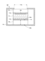
- FIG. 5 shows an example in which the frame 119 holding the reflector unit cell 102 has the function of the metal film 116. Specifically, an example will be shown in which a frame 119 made of a material that reflects radio waves is provided in the reflector unit cell 102 so as to face the substrate 106.
- the radio wave reflecting device 100a when using the frame 119 in the radio wave reflecting devices 100a and 100b, which will be described later, a plurality of reflector unit cells 102 are used, but instead of providing an opening 119a in each of the reflector unit cells 102, the radio wave reflecting device 100a Depending on the size of the reflector unit cells 102 or 100b, one may be provided for each of a certain number of reflector unit cells 102. However, the number of openings 119a is not limited.
- the step of forming the metal film 116 can be omitted in the manufacturing process of the radio wave reflecting device 100. Further, by providing the frame 119 having a thickness equal to or greater than the thickness of the metal film 116, it is possible to easily obtain the amplitude of the reflected wave equal to or greater than that of the metal film 116.
- the metal film 116 may be provided on a substrate 117 different from the substrate 106 on which the common electrode 110 is provided, or the frame 119 having radio wave reflective properties may be provided so that the metal film 116 or the frame 119 faces the substrate 106. Then, the frame 119 can be retrofitted to the reflector unit cell 102. These retrofits can simplify the process of manufacturing the reflector unit cell 102 and shorten the time.
- Radio Wave Reflector Next, the configuration of a radio wave reflector in which reflector units are integrated will be shown.
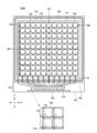
- FIG. 6 shows the configuration of a radio wave reflecting device 100a according to an embodiment of the present invention.
- the radio wave reflection device 100a has a reflection plate 120.
- the reflector 120 is composed of a plurality of reflector unit cells 102.
- the plurality of reflector unit cells 102 are arranged, for example, in a first direction (X-axis direction shown in FIG. 6) and a second direction (Y-axis direction shown in FIG. 6) intersecting the first direction.
- the reflector unit cell 102 is arranged so that the patch electrode 108 faces the radio wave incident surface.
- the reflecting plate 120 has a flat plate shape, and a plurality of patch electrodes 108 are arranged in a matrix within the flat plane.
- the radio wave reflecting device 100 has a structure in which a plurality of reflector unit cells 102 are integrated on one substrate 104. As shown in FIG. 6, the radio wave reflecting device 100 has a substrate 104 on which a plurality of patch electrodes 108 are arranged, and a substrate 106 on which a common electrode 110 and a metal film 116 are provided, which are arranged one on top of the other, and between the two substrates. It has a structure in which a liquid crystal layer (not shown) is provided on the top. At this time, the surface of the substrate 106 on which the common electrode 110 is provided faces the liquid crystal layer (not shown).
- the reflective plate 120 is formed in a region where the plurality of patch electrodes 108, the common electrode 110, and the metal film 116 overlap.
- the cross-sectional structure of the reflector 120 is the same as the structure of the reflector unit cell 102 shown in FIG. 1B when looking at the individual patch electrodes 108.
- the metal film 116 is arranged inside the sealing material 128 and overlaps with the reflecting plate 120 in a plan view, but it may be provided wider than the reflecting plate 120 and in an overlapping manner. It may be provided so as to spread outward from the sealing material 128.
- the substrate 104 and the substrate 106 are bonded together with a sealant 128, and a liquid crystal layer (not shown) is provided in an area inside the sealant 128.
- a frame 119 (not shown) can be provided as shown in FIG.
- the frame 119 is provided so that the reflector 120 is exposed, and the opening 119a of the frame 119 overlaps with the reflector 120.
- a frame 119 (not shown) can be provided to protect and hold a structure mounted on the radio wave reflecting device 100a.
- a frame 119 (not shown) surrounds the substrate 104 and the substrate 106, and is arranged to sandwich the substrate 104 and the substrate 106 in a cross-sectional view. At this time, one or more openings 119a of the frame 119 may be provided depending on the size of the radio wave reflecting device 100a or the patch electrode 108.
- a plurality of patch electrodes 108 are arranged on the substrate 104 in the first direction (X-axis direction) and the second direction (Y-axis direction). Further, a plurality of first wirings 118 extending in the second direction (Y-axis direction) are arranged on the substrate 104. Each of the plurality of first wirings 118 is electrically connected to the plurality of patch electrodes 108 arranged in the second direction (Y-axis direction). In other words, the plurality of patch electrodes 108 arranged in the second direction (Y-axis direction) are connected by the first wiring 118.
- the reflecting plate 120 has a configuration in which a plurality of patch electrode arrays are arranged in a first direction (X-axis direction) in a row connected by first wiring 118.
- a plurality of first wirings 118 arranged on the reflection plate 120 extend to the peripheral region 122 and are connected to the first drive circuit 124.
- the first drive circuit 124 outputs a control signal to be applied to the patch electrode 108.
- the first drive circuit 124 can output control signals of different voltage levels to each of the plurality of first wirings 118.
- the plurality of patch electrodes 108 arranged in the first direction (X-axis direction) and the second direction (Y-axis direction) are arranged column by column (in the second direction (Y-axis direction)).
- a control signal is applied to each patch electrode 108).
- a control signal is applied to each set of a plurality of patch electrodes 108 arranged in a second direction (Y-axis direction), thereby controlling the reflection direction of the reflected radio waves incident on the reflection plate 120.
- the radio wave reflecting device 100a can control the propagation direction of the reflected waves in the horizontal direction in the drawing centering on the reflection axis VR parallel to the second direction (Y-axis direction). can.
- FIG. 7 schematically shows that the traveling direction of reflected waves changes due to the two reflector unit cells 102.
- different control signals V1 ⁇ V2
- V1 ⁇ V2 different control signals
- the phase change of the wave reflected by the second reflector unit cell 102b is larger than that of the first reflector unit cell 102a.
- the phase of the reflected wave R1 reflected by the first reflector unit cell 102a and the phase of the reflected wave R2 reflected by the second reflector unit cell 102b are different (in FIG. 7, the phase of the reflected wave R2 is different from the phase of the reflected wave R1). ), the traveling direction of the reflected wave appears to change diagonally.
- the plurality of patch electrodes 108 arranged in the second direction are electrically connected by the first wiring 118 and have an electrically equal potential, so that the shape is divided into a plurality of parts.
- the dimensions of the patch electrode 108 have an appropriate range depending on the wavelength of the reflected radio waves, so if the electrode is shaped like a strip, the sensitivity to the target wavelength will decrease, and the behavior for vertically polarized waves and horizontally polarized waves will differ. Put it away. Therefore, as shown in FIG.
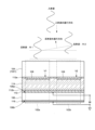
- FIG. 8 shows the configuration of a radio wave reflection device 100b according to this embodiment.
- the parts that are different from the radio wave reflecting device 100a shown in FIG. 5 will be mainly explained.
- first connection wiring 144 is provided in the same layer as the conductive layer forming the first wiring 118.
- the first connection wiring 144 is provided so as to be in contact with the semiconductor layer 142.
- the connection structure of the first wiring 118 and the first connection wiring 144 to the semiconductor layer 142 shows a structure in which one wiring is connected to the source of the transistor and the other wiring is connected to the drain.
- the undercoat layer 136 is formed of, for example, a silicon oxide film.
- the first gate insulating layer 140 and the second gate insulating layer 146 are formed of, for example, a silicon oxide film or a laminated structure of a silicon oxide film and a silicon nitride film.
- the semiconductor layer is formed of a silicon semiconductor such as amorphous silicon or polycrystalline silicon, or an oxide semiconductor containing a metal oxide such as indium oxide, zinc oxide, or gallium oxide.
- the first gate electrode 138 and the second gate electrode 148 may be made of, for example, molybdenum (Mo), tungsten (W), or an alloy thereof.
- the first wiring 118, the second wiring 132, the first connection wiring 144, and the second connection wiring 152 are formed using a metal material such as titanium (Ti), aluminum (Al), or molybdenum (Mo).
- a metal material such as titanium (Ti), aluminum (Al), or molybdenum (Mo).
- it may have a laminated structure of titanium (Ti)/aluminum (Al)/titanium (Ti) or a laminated structure of molybdenum (Mo)/aluminum (Al)/molybdenum (Mo).
- the planarization layer 156 is made of a resin material such as acrylic or polyimide.
- the passivation layer 158 is formed of, for example, a silicon nitride film.
- the patch electrode 108 and the common electrode 110 are formed of a metal film such as aluminum (Al) or copper (Cu), or a transparent conductive film such as indium tin oxide (ITO).
- the second wiring 132 is connected to the gate of the transistor used as the switching element 134
- the first wiring 118 is connected to one of the source and drain of the transistor
- the patch electrode 108 is connected to the other of the source and drain.
- a control signal can be applied to a predetermined patch electrode selected from among the plurality of patch electrodes 108 arranged in a matrix.
- a control voltage can be applied to each patch electrode 108 arranged in a vertical line along the axial direction. can be controlled.
- the radio wave reflecting device 100 has the metal film 116 formed on the side opposite to the liquid crystal layer of the common electrode 110 forming the reflecting plate 120, By setting the value obtained by multiplying the distance T between the metal film 116 and the wavelength ⁇ of the radio waves irradiated to the patch electrode 108 to 0.02 or more and 0.34 or less, or 0.10 or more and 0.22 or less, reflection can be reduced. Gain can be increased.
- radio wave reflecting device and the reflecting plate unit illustrated as an embodiment of the present invention can be appropriately combined as long as they do not contradict each other.
- those skilled in the art may appropriately add, delete, or change the design of components, or add, omit, or condition a process. Modifications are also included within the scope of the present invention as long as they have the gist of the present invention.
Landscapes
- Physics & Mathematics (AREA)
- Nonlinear Science (AREA)
- Chemical & Material Sciences (AREA)
- Crystallography & Structural Chemistry (AREA)
- General Physics & Mathematics (AREA)
- Optics & Photonics (AREA)
- Mathematical Physics (AREA)
- Geometry (AREA)
- Electromagnetism (AREA)
- Aerials With Secondary Devices (AREA)
Priority Applications (3)
| Application Number | Priority Date | Filing Date | Title |
|---|---|---|---|
| CN202380045375.7A CN119343835A (zh) | 2022-06-21 | 2023-04-10 | 电波反射装置 |
| JP2024528327A JPWO2023248584A1 (https=) | 2022-06-21 | 2023-04-10 | |
| US18/964,732 US20250093708A1 (en) | 2022-06-21 | 2024-12-02 | Reflecting device |
Applications Claiming Priority (2)
| Application Number | Priority Date | Filing Date | Title |
|---|---|---|---|
| JP2022-099604 | 2022-06-21 | ||
| JP2022099604 | 2022-06-21 |
Related Child Applications (1)
| Application Number | Title | Priority Date | Filing Date |
|---|---|---|---|
| US18/964,732 Continuation US20250093708A1 (en) | 2022-06-21 | 2024-12-02 | Reflecting device |
Publications (1)
| Publication Number | Publication Date |
|---|---|
| WO2023248584A1 true WO2023248584A1 (ja) | 2023-12-28 |
Family
ID=89379484
Family Applications (1)
| Application Number | Title | Priority Date | Filing Date |
|---|---|---|---|
| PCT/JP2023/014623 Ceased WO2023248584A1 (ja) | 2022-06-21 | 2023-04-10 | 電波反射装置 |
Country Status (4)
| Country | Link |
|---|---|
| US (1) | US20250093708A1 (https=) |
| JP (1) | JPWO2023248584A1 (https=) |
| CN (1) | CN119343835A (https=) |
| WO (1) | WO2023248584A1 (https=) |
Citations (6)
| Publication number | Priority date | Publication date | Assignee | Title |
|---|---|---|---|---|
| JP2003529259A (ja) * | 2000-03-29 | 2003-09-30 | エイチアールエル ラボラトリーズ,エルエルシー | 電子同調可能反射器 |
| US20160241217A1 (en) * | 2015-02-13 | 2016-08-18 | Mohsen Sazegar | Counter electrode device, system and method for varying the permittivity of a liquid crystal device |
| WO2017061526A1 (ja) * | 2015-10-09 | 2017-04-13 | シャープ株式会社 | 走査アンテナおよびその駆動方法 |
| JP2018147051A (ja) * | 2017-03-01 | 2018-09-20 | 株式会社ジャパンディスプレイ | 表示装置 |
| JP2019530387A (ja) * | 2016-09-22 | 2019-10-17 | 華為技術有限公司Huawei Technologies Co.,Ltd. | ビーム・ステアリング・アンテナのための液晶調整可能メタサーフェス |
| WO2021202962A1 (en) * | 2020-04-03 | 2021-10-07 | Kymeta Corporation | Rf element design for improved tuning range |
-
2023
- 2023-04-10 WO PCT/JP2023/014623 patent/WO2023248584A1/ja not_active Ceased
- 2023-04-10 JP JP2024528327A patent/JPWO2023248584A1/ja active Pending
- 2023-04-10 CN CN202380045375.7A patent/CN119343835A/zh active Pending
-
2024
- 2024-12-02 US US18/964,732 patent/US20250093708A1/en active Pending
Patent Citations (6)
| Publication number | Priority date | Publication date | Assignee | Title |
|---|---|---|---|---|
| JP2003529259A (ja) * | 2000-03-29 | 2003-09-30 | エイチアールエル ラボラトリーズ,エルエルシー | 電子同調可能反射器 |
| US20160241217A1 (en) * | 2015-02-13 | 2016-08-18 | Mohsen Sazegar | Counter electrode device, system and method for varying the permittivity of a liquid crystal device |
| WO2017061526A1 (ja) * | 2015-10-09 | 2017-04-13 | シャープ株式会社 | 走査アンテナおよびその駆動方法 |
| JP2019530387A (ja) * | 2016-09-22 | 2019-10-17 | 華為技術有限公司Huawei Technologies Co.,Ltd. | ビーム・ステアリング・アンテナのための液晶調整可能メタサーフェス |
| JP2018147051A (ja) * | 2017-03-01 | 2018-09-20 | 株式会社ジャパンディスプレイ | 表示装置 |
| WO2021202962A1 (en) * | 2020-04-03 | 2021-10-07 | Kymeta Corporation | Rf element design for improved tuning range |
Also Published As
| Publication number | Publication date |
|---|---|
| JPWO2023248584A1 (https=) | 2023-12-28 |
| US20250093708A1 (en) | 2025-03-20 |
| CN119343835A (zh) | 2025-01-21 |
Similar Documents
| Publication | Publication Date | Title |
|---|---|---|
| WO2023058399A1 (ja) | 電波反射装置 | |
| US20250015508A1 (en) | Reflect array | |
| US20240364008A1 (en) | Reflect array | |
| US20250149800A1 (en) | Reflecting device | |
| US20250147347A1 (en) | Method for inspecting reflecting device | |
| WO2023248584A1 (ja) | 電波反射装置 | |
| WO2024116573A1 (ja) | 電波反射装置 | |
| US20250379366A1 (en) | Intelligent reflecting surface and reflecting device | |
| US20250379367A1 (en) | Intelligent reflecting surface | |
| US20260011928A1 (en) | Intelligent reflecting surface | |
| US20260003234A1 (en) | Intelligent reflecting surface | |
| US20250266865A1 (en) | Intelligent reflecting surface | |
| US20250219681A1 (en) | Intelligent reflecting surface | |
| US20250226588A1 (en) | Intelligent reflecting surface | |
| US12578599B2 (en) | Reflecting device having liquid crystal material | |
| US20260024919A1 (en) | Intelligent reflecting surface | |
| US20260005436A1 (en) | Reflecting element for intelligent reflecting surface | |
| US20250309554A1 (en) | Intelligent reflecting surface | |
| KR20250091286A (ko) | 전파 반사 장치 | |
| WO2025027981A1 (ja) | 電波反射装置の検査装置、およびその検査方法 | |
| WO2026088586A1 (ja) | 電波反射装置 | |
| WO2025142111A1 (ja) | 電波反射板および電波反射装置 | |
| WO2025052894A1 (ja) | 電波反射装置及びこれを含む電波反射システム | |
| WO2024180881A1 (ja) | 電波反射板 |
Legal Events
| Date | Code | Title | Description |
|---|---|---|---|
| 121 | Ep: the epo has been informed by wipo that ep was designated in this application |
Ref document number: 23826773 Country of ref document: EP Kind code of ref document: A1 |
|
| WWE | Wipo information: entry into national phase |
Ref document number: 2024528327 Country of ref document: JP |
|
| WWE | Wipo information: entry into national phase |
Ref document number: 202380045375.7 Country of ref document: CN |
|
| WWP | Wipo information: published in national office |
Ref document number: 202380045375.7 Country of ref document: CN |
|
| NENP | Non-entry into the national phase |
Ref country code: DE |
|
| 122 | Ep: pct application non-entry in european phase |
Ref document number: 23826773 Country of ref document: EP Kind code of ref document: A1 |