WO2023248397A1 - 半導体装置 - Google Patents
半導体装置 Download PDFInfo
- Publication number
- WO2023248397A1 WO2023248397A1 PCT/JP2022/024982 JP2022024982W WO2023248397A1 WO 2023248397 A1 WO2023248397 A1 WO 2023248397A1 JP 2022024982 W JP2022024982 W JP 2022024982W WO 2023248397 A1 WO2023248397 A1 WO 2023248397A1
- Authority
- WO
- WIPO (PCT)
- Prior art keywords
- casing
- sealing material
- sealant
- semiconductor device
- flow path
- Prior art date
- Legal status (The legal status is an assumption and is not a legal conclusion. Google has not performed a legal analysis and makes no representation as to the accuracy of the status listed.)
- Ceased
Links
Images


Classifications
-
- H—ELECTRICITY
- H10—SEMICONDUCTOR DEVICES; ELECTRIC SOLID-STATE DEVICES NOT OTHERWISE PROVIDED FOR
- H10W—GENERIC PACKAGES, INTERCONNECTIONS, CONNECTORS OR OTHER CONSTRUCTIONAL DETAILS OF DEVICES COVERED BY CLASS H10
- H10W40/00—Arrangements for thermal protection or thermal control
- H10W40/40—Arrangements for thermal protection or thermal control involving heat exchange by flowing fluids
- H10W40/47—Arrangements for thermal protection or thermal control involving heat exchange by flowing fluids by flowing liquids, e.g. forced water cooling
-
- H—ELECTRICITY
- H05—ELECTRIC TECHNIQUES NOT OTHERWISE PROVIDED FOR
- H05K—PRINTED CIRCUITS; CASINGS OR CONSTRUCTIONAL DETAILS OF ELECTRIC APPARATUS; MANUFACTURE OF ASSEMBLAGES OF ELECTRICAL COMPONENTS
- H05K7/00—Constructional details common to different types of electric apparatus
- H05K7/20—Modifications to facilitate cooling, ventilating, or heating
- H05K7/2089—Modifications to facilitate cooling, ventilating, or heating for power electronics, e.g. for inverters for controlling motor
- H05K7/20927—Liquid coolant without phase change
Definitions
- the present invention relates to a semiconductor device.
- Patent Document 1 listed below discloses a power conversion device having a structure in which a surface where a sealing material is applied has a double groove and a protrusion in a joint portion between housings. .
- Patent Document 1 Although there is no problem with the sealing itself, contact of the sealing material with the refrigerant flow path may cause deterioration in assembly due to corrosion. In view of this, it is an object of the present invention to provide a semiconductor device that can both prevent a decrease in adhesive strength and prevent adhesive from flowing into a coolant flow path.
- the semiconductor device has a power module that uses a semiconductor to output electric power to drive a motor, and adhesive surfaces, and the adhesive surfaces are adhered to each other to form a refrigerant flow path that cools the power module.
- the semiconductor device includes a first housing, a second housing, and a sealing material that seals the adhesive surface of the first housing and the second housing.
- the adhesive surface of either the body or the second casing has a sealant application part to which the sealant is applied, and the other adhesive surface has a sealant application part at a position corresponding to the sealant application part.
- a sealing material pressing part that presses the sealing material, and the adhesive surface of either the first casing or the second casing is closer to the refrigerant flow path than the sealing material application part.
- a sealing material inflow suppressing portion is provided at a position for suppressing the inflow of the sealing material into the refrigerant flow path.
- the present invention it is possible to provide a semiconductor device that can both prevent a decrease in adhesive strength and prevent adhesive from flowing into a coolant flow path.
- FIG. 1(a) is an explanatory diagram of a power module housed in a housing
- FIG. 1(b) is an explanatory diagram of a lower cover attached to the housing.
- a power module 3 that outputs electric power to drive a motor using a semiconductor is inserted into a case 5, and a power module plate 13 is assembled to the case 5 to accommodate the power module 3 in a sandwiched manner. ⁇ keeping.
- the lower cover 4 has a waterway pipe 14.
- the waterway pipe 14 is press-fitted into the lower cover 4.
- a sealing material (described later) is applied to the groove of the case 5, and the lower cover 4 is assembled to the case 5 so as to sandwich the sealing material.
- FIG. 2(a) is a sectional view taken along the line AA in FIG. 1(b), and FIG. 2(b) is an enlarged view of the housing connection portion in FIG. 2(a).
- the semiconductor device 1 has a power module 3, and a lower cover 4 is attached to the case 5 in order to house the power module 3 in the case 5. Thereby, a refrigerant flow path 2 that cools the power module 3 is formed.
- the lower cover 4 will be referred to as the first housing 4 and the case 5 will be referred to as the second housing 5.
- a sealing material 7 is used on the bonding surfaces.
- the sealing material 7 is, for example, a silicone-based adhesive, and adheres and seals the adhesive surfaces of the first casing 4 and the second casing 5.
- a groove formed by the seal material pressing section 9 and the seal material application section 10 and a seal material inflow suppressing section are formed in the connection section.
- Two grooves are formed, one by 8. Of these two grooves, the groove located on the outer peripheral side of the first housing 4 and the second housing 5 is located between the seal material pressing part 9 on the first housing 4 and the groove on the outer peripheral side of the second housing 5. This is a sealing material application section 10.
- the sealant application part 10 has a concave shape, and the sealant pressing part 9 has a convex shape with a protrusion. Further, the sealing material applying section 10 and the sealing material pressing section 9 are bonded together so as to surround the refrigerant flow path 2. In addition, the sealing material application part 10 may be trapezoidal in consideration of the ease with which the sealing material 7 flows.
- a groove formed in a position closer to the refrigerant flow path 2 than the sealant application part 10 is formed in the second casing.
- the body 5 has a sealing material inflow suppressing portion 8 in the shape of a recess.
- the seal material inflow suppressing portion 8 is formed to surround the refrigerant flow path 2 .
- a sealing material storage section 12 is provided outside the refrigerant flow path 2 of the first casing 4 and the second casing 5.
- sealing material application part 10 is not limited to the form illustrated in FIG. applied. Further, in that case, the sealant pressing portion 9 is formed on the other adhesive surface and presses the sealant 7 disposed on the sealant coating portion 10 at a position corresponding to the sealant coating portion 10 .
- the sealant applicator 10 and the sealant inflow suppressor 8 are arranged to control how the sealant 7 spreads when the first casing 4 and the second casing 5 are bonded together.
- the sealing material applicator 10 is located closer to the outer peripheral side than the coolant flow path 2 on the bonding surface between the first casing 4 and the second casing 5.
- the sealing material inflow suppressing portion 8 is located closer to the refrigerant flow path 2 than to the outer circumference side on the bonding surface between the first casing 4 and the second casing 5.
- the length from the position of the sealant application part 10 to the position of the sealant inflow suppressing part 8 is the first length 11a
- the length from the outer periphery of the adhesive surface to the position of the sealant application part 10 is the first length 11a.
- the first length 11a is longer than the second length 11b. That is, with respect to the sealing material application portion 10, the bonding area closer to the coolant flow path 2 is larger than that on the outer peripheral side of the bonding surface. This is because internal pressure is applied to the adhesive surface from the refrigerant in the refrigerant flow path 2, so that the first casing 4 expands due to the internal pressure.
- first length 11a the portion with a large bonding area (first length 11a) is arranged close to the refrigerant flow path 2. Furthermore, since the sealant 7 protrudes into the sealant inflow suppressing section 8 when the cases are bonded together, a wide range of bonding surface is ensured in the first length 11a to prevent the sealant 7 from protruding too much. ing.
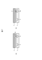
- FIG. 4(a) is a diagram showing the sealing material 7 applied to the sealing material application part 10
- FIG. 4(b) is a diagram showing the state in the process of bonding the first casing 4 and the second casing 5.
- FIG. 4(c) is a diagram showing the state when the first casing 4 and the second casing 5 are bonded together.
- FIGS. 4(a) to 4(c) show a series of processes for connecting cases.
- the sealant 7 is applied to the sealant application portion 10 of the second casing 5.
- the amount of the sealant 7 applied is controlled to a predetermined amount by a coating machine or the like, and the sealant 7, which is spread out in the left and right direction when the casings are bonded to each other, is kept in the sealant inflow suppressing section 8. Since it is adjusted so that the sealing material 7 can be prevented from flowing into the refrigerant flow path 2. Further, the width of the sealing material application section 10 is such that the amount of application of the sealing material 7 can be sufficiently received.
- the sealant pressing part 9 of the first casing 4 comes into contact with the sealant 7 applied to the sealant application part 10. and start pressing the sealing material 7.
- the sealing material pressing portion 9 bites into the sealing material 7, crushing the sealing material 7, and spreading it out.
- the adhesion area of the concave sealing material application part 10 and the convex sealing material pressing part 9 is the same, and they are provided so that there is no difference in adhesion, so that the sealing material 7 does not peel off at the interface and has sufficient adhesion. Can have power.
- the sealing material 7 is spread out in the horizontal direction of the adhesive surface. As a result, a part of the sealing material 7 accumulates in the groove of the sealing material inflow suppressing part 8 on the side of the refrigerant flow path 2, while a part of the sealing material 7 accumulates in the sealing material storage part 12 when it is pushed toward the outer peripheral part. becomes accumulated.
- the sealant pressing part 9 of the first casing 4 separates the air drawn into the sealant 7 and pushes it toward both ends of the bonding surface. Since the adhesive is discharged, the adhesion area in the sealant application section 10 can be secured. Furthermore, by making the adhesive strength uniform, the adhesive force of the adhesive surface is stabilized. Further, since the sealing material 7 is applied and pressed using only one groove instead of the double groove structure shown in the prior art, it is possible to improve the reliability of adhesion by preventing air entrainment.
- the end of the first casing 4 on the coolant flow path 2 side is the first end 4a
- the end of the first casing 4 on the outer peripheral side is the second end 4b
- the end of the second casing 5 on the coolant flow path 2 side is defined as a third end 5a
- the end of the second casing 5 on the outer peripheral side is defined as a fourth end 5b.
- the first housing 4 and the second housing 5 are bonded together so that the first end 4a and the third end 5a are in contact with each other, and the second end 4b and the fourth end 5b are in contact with each other. has been done.
- the sealing material 7 tends to adhere to the side of the case that has a large surface area when the cases are overlapped, which poses a problem in the reliability of the adhesion surface. This problem can be prevented by matching the lengths between the ends of the housing 5 and bonding them together. Further, since the first end 4a and the third end 5a are combined, there is an effect that the sealing material 7 does not flow into the refrigerant flow path 2 even if it is separated from the sealing material inflow suppressing part 8.
- first casing 4 and the second casing 5 are each provided with a sealing material reservoir 12 for storing the sealing material 7 at the outer periphery of the adhesive surface of each casing. This prevents the sealing material 7 from excessively protruding to the outer periphery of the adhesive surface, preventing salt accumulation from occurring in the protruding portion, and suppressing corrosion of the sealing material 7.
- the sealant application unit 10 is capable of discharging air while the sealant pressing unit 9 pushes and spreads the sealant 7 when the sealant 7 is applied and the first casing 4 is attached to the second casing 5. As such, both ends of the application section are not perpendicular, but sloped. This allows the sealing material 7 to flow easily when the casings are bonded together. Since the sealing material pressing part 9 is the center of the horizontal spread of the sealing material 7 during assembly, the way the sealing material 7 spreads can be controlled by the position and shape of the pressing part 9.
- At least one of the sealant pressing section 9 and the sealant application section 10 of the first casing 4 may be trapezoidal.
- FIG. 5A shows an example in which the sealing material pressing portion 9 is trapezoidal. Further, in FIG. 5A, the sealing material pressing section 9 and the sealing material application section 10 are located symmetrically with respect to the center line 16.
- the shape of the sealing material pressing portion 9 does not matter whether it is symmetrical or asymmetrical. Specifically, as shown in FIG. 5B, the position of the sealant pressing part 9 with respect to the width of the sealant applying part 10 is from the sealing material pressing part 9 to one end of the sealant applying part 10. The length 15a of the groove from the sealing material pressing part 9 to the other end of the sealing material application part 10 may be arranged so as to have different lengths. Further, as shown in FIG. 5(c), the sealing material pressing portion 9 may be a sealing material pressing portion 9a having an asymmetric shape with respect to the center line 16.
- the sealing material inflow suppressing section 8 may be provided in either the first casing 4 or the second casing 5. Further, the sealant pressing section 9 and the sealant applying section 10 can be connected to the first housing 4 or The arrangement can be done independently of which side of the second casing 5 it is attached to.
- FIG. 6A shows an example in which the sealing material inflow suppressing section 8 and the sealing material applicator 10 are arranged in the second casing 5, and the sealing material pressing section 9 is arranged in the first casing 4.
- FIG. 6B shows an example in which the sealant inflow suppressing section 8 and the sealing material pressing section 9 are arranged in the first casing 4, and the sealing material applicator 10 is arranged in the second casing 5.
- FIG. 6C shows an example in which the sealing material inflow suppressing section 8 and the sealing material applicator 10 are arranged in the first casing 4, and the sealing material pressing section 9 is arranged in the second casing 5.
- FIG. 6D shows an example in which the sealant applicator 10 is arranged in the first casing 4, and the sealant inflow suppressing part 8 and the sealing material pressing part 9 are arranged in the second casing 5.
- a seal material pressing portion 9b having a groove around the pressing portion can also have the same effect.
- the sealing material pressing portion 9 can be formed by simple processing.
- the sealing material application section 10 does not have to have an adhesion area corresponding to the sealing material pressing section 9, and the sealing material pressing section 9 is located at the center of the sealing material application section 10. It is also possible to have a shape that is not arranged so that it comes to the center.
- a sealing material pressing part 9 that presses the sealing material 7 at a corresponding position, and the refrigerant flow is lower than that of the sealing material application part 10 on the adhesive surface of either the first casing 4 or the second casing 5.
- a sealing material inflow suppressing portion 8 that suppresses the inflow of the sealing material 7 into the refrigerant flow path 2 is provided at a position close to the path 2 . By doing so, it is possible to provide a semiconductor device 1 that can prevent both adhesive strength from decreasing and adhesive from flowing into the coolant flow path.
- the sealant application part 10 has a concave shape
- the sealant pressing part 9 has a convex shape
- the sealant application part 10 and the sealant pressing part 9 are bonded to surround the refrigerant flow path 2. ing.
- the refrigerant flow path 2 is formed by the casing with a stable adhesive surface.
- At least either the sealant applying section 10 or the sealant pressing section 9 has a trapezoidal shape. This makes it easier for the sealing material 7 to flow.
- the sealing material inflow suppressing portion 8 has a concave shape and is formed to surround the refrigerant flow path 2. By doing this, the way the sealant 7 spreads is controlled so that the sealant 7 does not flow into the coolant flow path 2 while ensuring the reliability of the adhesive surface.
- the length from the position of the sealant application section 10 to the position of the sealant inflow suppressing section 8 is greater than the length from the outer periphery of the bonding surface to the position of the sealant application section 10. .
- the adhesive surface of the first casing 4 has a first end 4a, which is the end on the refrigerant flow path 2 side, and a second end 4b, which is the end on the outer peripheral side.
- the adhesive surface of the casing 5 has a third end 5a that is the end on the refrigerant flow path 2 side and a fourth end 5b that is the end on the outer circumferential side, and
- the housing 5 is bonded so that the first end 4a and the third end 5a are in contact with each other, and the second end 4b and the fourth end 5b are in contact with each other. By doing so, it is possible to prevent the sealing material 7 from entering the refrigerant flow path 2.
- the first casing 4 and the second casing 5 each have a sealing material reservoir 12 that stores the sealing material 7 at the outer periphery of the adhesive surface of each casing. By doing so, corrosion of the sealing material 7 can be suppressed by preventing salt accumulation from occurring in the protruding portion.
Landscapes
- Engineering & Computer Science (AREA)
- Microelectronics & Electronic Packaging (AREA)
- Physics & Mathematics (AREA)
- Thermal Sciences (AREA)
- Cooling Or The Like Of Semiconductors Or Solid State Devices (AREA)
Abstract
Description
(図1)
図1(a)は筐体に収納するパワーモジュールについての説明図、図1(b)は筐体に取り付けるロアーカバーについての説明図である。半導体装置1は、ケース5に半導体を用いてモータを駆動する電力を出力するパワーモジュール3が挿入されており、パワーモジュールプレート13がケース5に組付けられることによって、挟むようにしてパワーモジュール3を収納・保持している。
図2(a)は図1(b)のA-A断面図、図2(b)は図2(a)の筐体接続部の拡大図である。半導体装置1は、パワーモジュール3を有し、パワーモジュール3をケース5内に収納するためにロアーカバー4をケース5に取り付けている。これにより、パワーモジュール3を冷却する冷媒流路2が形成される。以下の説明以降、ロアーカバー4を第1の筐体4、ケース5を第2の筐体5として説明する。
シール材塗布部10とシール材流入抑制部8は、第1の筐体4と第2の筐体5との接着時に、シール材7の広がり方をコントロールする配置である。シール材塗布部10の位置は、第1の筐体4と第2の筐体5との接着面において、冷媒流路2よりも外周部側に近い位置に配置する。一方で、シール材流入抑制部8の位置は、第1の筐体4と第2の筐体5との接着面において、外周部側よりも冷媒流路2に近い位置に配置する。
図4(a)はシール材塗布部10にシール材7を塗布した図、図4(b)は第1の筐体4と第2の筐体5とが接着する途中の様子を表した図、図4(c)は第1の筐体4と第2の筐体5とが接着した時の様子を表した図である。図4(a)~図4(c)で筐体同士の接続の一連のプロセスを表している。
シール材塗布部10は、シール材7が塗布され第1の筐体4が第2の筐体5に取り付けられる際に、シール材押圧部9がシール材7を押し広げながらエアーを排出が出来るよう、塗布部両端は直角の形状ではなく、斜面の形状が設けられている。これにより、筐体同士の接着時にシール材7を流動しやすいようにする。シール材押圧部9は組み立て時におけるシール材7の左右の広がりの中心となるため、押圧部9の位置や形状によりシール材7の広がり方をコントロールできる。
(図6)
シール材流入抑制部8は第1の筐体4または第2の筐体5のどちらに設けてもよい。また、シール材押圧部9とシール材塗布部10は、接着時にシール材押圧部9がシール材塗布部10に収納されてさえいれば、シール材流入抑制部8が第1の筐体4または第2の筐体5のどちらについているかに依存せずに配置することができる。
(図7)
図7(a)に示すように、押圧部の周囲に溝を有したシール材押圧部9bでも同様の効果を奏することができ、これにより、溝を有さないシール材押圧部9よりも、簡易的な加工でシール材押圧部9を形成できる。また、図7(b)に示すように、シール材塗布部10は、シール材押圧部9に対応した接着面積でなくてもよく、また、シール材押圧部9がシール材塗布部10の中心に来るような配置にしない形状であってもよい。
2 冷媒流路
3 パワーモジュール
4 ロアーカバー(第1の筐体)
4a 第1端部
4b 第2端部
5 ケース(第2の筐体)
5a 第3端部
5b 第4端部
6 筐体接続部
7 シール材
8 シール材流入抑制部
9 シール材押圧部
9a アシンメトリーの押圧部
9b 周囲に溝を有した押圧部
10 シール材塗布部
10a 大きい溝を有した塗布部
11 長さ
11a 第1の長さ
11b 第2の長さ
12 シール材貯留部
13 パワーモジュールプレート
14 水路パイプ
15 長さ
15a 第1の溝の長さ
15b 第2の溝の長さ
16 中心線
Claims (7)
- 半導体を用いてモータを駆動する電力を出力するパワーモジュールと、
接着面をそれぞれ有し、前記接着面同士が互いに接着されることで前記パワーモジュールを冷却する冷媒流路を形成する第1の筐体および第2の筐体と、
前記第1の筐体と前記第2の筐体との前記接着面をシールするシール材と、を備えた半導体装置において、
前記第1の筐体または前記第2の筐体のどちらか一方の前記接着面において、前記シール材が塗布されるシール材塗布部を有し、
他方の前記接着面において、前記シール材塗布部に対応する位置に前記シール材を押圧するシール材押圧部を有し、
前記第1の筐体または前記第2の筐体のどちらか一方の前記接着面において、前記シール材塗布部よりも前記冷媒流路に近い位置に、前記冷媒流路内への前記シール材の流入を抑制するシール材流入抑制部を有している
半導体装置。 - 請求項1に記載の半導体装置であって、
前記シール材塗布部は、凹部形状であり、
前記シール材押圧部は、凸部形状であり、
前記シール材塗布部と前記シール材押圧部は、前記冷媒流路を取り囲むようにして接着されている
半導体装置。 - 請求項1に記載の半導体装置であって、
前記シール材塗布部または前記シール材押圧部の少なくともどちらか一方は、台形状である
半導体装置。 - 請求項1に記載の半導体装置であって、
前記シール材流入抑制部は凹部形状であり、前記冷媒流路を取り囲むようにして形成されている
半導体装置。 - 請求項1に記載の半導体装置であって、
前記接着面において、前記接着面の外周部から前記シール材塗布部の位置までの長さよりも、前記シール材塗布部の位置から前記シール材流入抑制部の位置までの長さの方が大きい
半導体装置。 - 請求項1に記載の半導体装置であって、
前記第1の筐体の前記接着面は、前記冷媒流路側の端部である第1端部と外周部側の端部である第2端部を有し、
前記第2の筐体の前記接着面は、前記冷媒流路側の端部である第3端部と外周部側の端部である第4端部を有し、
前記第1の筐体と前記第2の筐体は、前記第1端部と前記第3端部が接触し、かつ前記第2端部と前記第4端部とが接触するように、接着される
半導体装置。 - 請求項1~6のいずれか一項に記載の半導体装置であって、
前記第1の筐体および前記第2の筐体は、それぞれの当該筐体の前記接着面の外周部において前記シール材を溜めておくシール材貯留部を有する
半導体装置。
Priority Applications (4)
| Application Number | Priority Date | Filing Date | Title |
|---|---|---|---|
| DE112022007026.9T DE112022007026T5 (de) | 2022-06-22 | 2022-06-22 | Halbleitervorrichtung |
| JP2024528186A JP7799830B2 (ja) | 2022-06-22 | 2022-06-22 | 半導体装置 |
| PCT/JP2022/024982 WO2023248397A1 (ja) | 2022-06-22 | 2022-06-22 | 半導体装置 |
| CN202280096767.1A CN119318017A (zh) | 2022-06-22 | 2022-06-22 | 半导体器件 |
Applications Claiming Priority (1)
| Application Number | Priority Date | Filing Date | Title |
|---|---|---|---|
| PCT/JP2022/024982 WO2023248397A1 (ja) | 2022-06-22 | 2022-06-22 | 半導体装置 |
Publications (1)
| Publication Number | Publication Date |
|---|---|
| WO2023248397A1 true WO2023248397A1 (ja) | 2023-12-28 |
Family
ID=89379285
Family Applications (1)
| Application Number | Title | Priority Date | Filing Date |
|---|---|---|---|
| PCT/JP2022/024982 Ceased WO2023248397A1 (ja) | 2022-06-22 | 2022-06-22 | 半導体装置 |
Country Status (4)
| Country | Link |
|---|---|
| JP (1) | JP7799830B2 (ja) |
| CN (1) | CN119318017A (ja) |
| DE (1) | DE112022007026T5 (ja) |
| WO (1) | WO2023248397A1 (ja) |
Citations (5)
| Publication number | Priority date | Publication date | Assignee | Title |
|---|---|---|---|---|
| JP2006287037A (ja) * | 2005-04-01 | 2006-10-19 | Toyota Industries Corp | 電子機器 |
| JP2006310381A (ja) * | 2005-04-26 | 2006-11-09 | Toyota Industries Corp | 電子機器 |
| JP2012009734A (ja) * | 2010-06-28 | 2012-01-12 | Denso Corp | 半導体モジュールの積層体及びその製造方法 |
| JP2016146451A (ja) * | 2015-02-09 | 2016-08-12 | 株式会社日本自動車部品総合研究所 | 冷却器付き半導体装置 |
| JP2021005638A (ja) * | 2019-06-26 | 2021-01-14 | 日立オートモティブシステムズ株式会社 | 直接冷却型半導体装置およびその製造方法 |
Family Cites Families (1)
| Publication number | Priority date | Publication date | Assignee | Title |
|---|---|---|---|---|
| JP2016092209A (ja) | 2014-11-05 | 2016-05-23 | 三菱電機株式会社 | 電力半導体装置、および電力半導体装置の製造方法 |
-
2022
- 2022-06-22 WO PCT/JP2022/024982 patent/WO2023248397A1/ja not_active Ceased
- 2022-06-22 CN CN202280096767.1A patent/CN119318017A/zh active Pending
- 2022-06-22 DE DE112022007026.9T patent/DE112022007026T5/de active Pending
- 2022-06-22 JP JP2024528186A patent/JP7799830B2/ja active Active
Patent Citations (5)
| Publication number | Priority date | Publication date | Assignee | Title |
|---|---|---|---|---|
| JP2006287037A (ja) * | 2005-04-01 | 2006-10-19 | Toyota Industries Corp | 電子機器 |
| JP2006310381A (ja) * | 2005-04-26 | 2006-11-09 | Toyota Industries Corp | 電子機器 |
| JP2012009734A (ja) * | 2010-06-28 | 2012-01-12 | Denso Corp | 半導体モジュールの積層体及びその製造方法 |
| JP2016146451A (ja) * | 2015-02-09 | 2016-08-12 | 株式会社日本自動車部品総合研究所 | 冷却器付き半導体装置 |
| JP2021005638A (ja) * | 2019-06-26 | 2021-01-14 | 日立オートモティブシステムズ株式会社 | 直接冷却型半導体装置およびその製造方法 |
Also Published As
| Publication number | Publication date |
|---|---|
| CN119318017A (zh) | 2025-01-14 |
| DE112022007026T5 (de) | 2025-02-20 |
| JPWO2023248397A1 (ja) | 2023-12-28 |
| JP7799830B2 (ja) | 2026-01-15 |
Similar Documents
| Publication | Publication Date | Title |
|---|---|---|
| JP5380750B2 (ja) | ワイヤハーネス及びその製造方法 | |
| JP5380751B2 (ja) | ワイヤハーネス及びその製造方法 | |
| US20140197605A1 (en) | Plate-integrated gasket | |
| JP2019046842A (ja) | シール構造 | |
| CN111836512B (zh) | 冷却器 | |
| KR200474790Y1 (ko) | 파이프 연결구 | |
| JP7426775B2 (ja) | 密封構造 | |
| WO2013176108A1 (ja) | ガスケット | |
| JP7799830B2 (ja) | 半導体装置 | |
| JP7003967B2 (ja) | 電力変換装置 | |
| JP2003156002A (ja) | アキュムレータ | |
| JP6981447B2 (ja) | 電力変換装置 | |
| WO2020095547A1 (ja) | ガスケット | |
| JP5111338B2 (ja) | 筐体構造 | |
| JP5407058B2 (ja) | ワイヤハーネス及びその製造方法 | |
| JP3766749B2 (ja) | 電磁弁 | |
| JP5413675B2 (ja) | 電力変換装置 | |
| JP5278304B2 (ja) | ワイヤハーネス及びその製造方法 | |
| WO2023248566A1 (ja) | 電力変換装置 | |
| JP2000230640A (ja) | シリンダヘッドガスケット | |
| CN112134397B (zh) | 一种电机出线端密封装置及电机 | |
| JP2011159591A (ja) | ワイヤハーネス及びその製造方法 | |
| JP2003163473A (ja) | ハウジングのシール構造 | |
| JP3052890U (ja) | シール用リング | |
| JP2006170262A (ja) | 管の接合構造 |
Legal Events
| Date | Code | Title | Description |
|---|---|---|---|
| 121 | Ep: the epo has been informed by wipo that ep was designated in this application |
Ref document number: 22947958 Country of ref document: EP Kind code of ref document: A1 |
|
| ENP | Entry into the national phase |
Ref document number: 2024528186 Country of ref document: JP Kind code of ref document: A |
|
| WWE | Wipo information: entry into national phase |
Ref document number: 202280096767.1 Country of ref document: CN |
|
| WWE | Wipo information: entry into national phase |
Ref document number: 112022007026 Country of ref document: DE Ref document number: 18872895 Country of ref document: US |
|
| WWP | Wipo information: published in national office |
Ref document number: 202280096767.1 Country of ref document: CN |
|
| WWP | Wipo information: published in national office |
Ref document number: 112022007026 Country of ref document: DE |
|
| 122 | Ep: pct application non-entry in european phase |
Ref document number: 22947958 Country of ref document: EP Kind code of ref document: A1 |