WO2023248382A1 - 制御装置、制御システム、制御方法およびプログラム - Google Patents
制御装置、制御システム、制御方法およびプログラム Download PDFInfo
- Publication number
- WO2023248382A1 WO2023248382A1 PCT/JP2022/024921 JP2022024921W WO2023248382A1 WO 2023248382 A1 WO2023248382 A1 WO 2023248382A1 JP 2022024921 W JP2022024921 W JP 2022024921W WO 2023248382 A1 WO2023248382 A1 WO 2023248382A1
- Authority
- WO
- WIPO (PCT)
- Prior art keywords
- information
- address
- static address
- control
- unit
- Prior art date
- Legal status (The legal status is an assumption and is not a legal conclusion. Google has not performed a legal analysis and makes no representation as to the accuracy of the status listed.)
- Ceased
Links
Images






Classifications
-
- H—ELECTRICITY
- H04—ELECTRIC COMMUNICATION TECHNIQUE
- H04L—TRANSMISSION OF DIGITAL INFORMATION, e.g. TELEGRAPHIC COMMUNICATION
- H04L61/00—Network arrangements, protocols or services for addressing or naming
- H04L61/50—Address allocation
- H04L61/5007—Internet protocol [IP] addresses
- H04L61/5014—Internet protocol [IP] addresses using dynamic host configuration protocol [DHCP] or bootstrap protocol [BOOTP]
-
- H—ELECTRICITY
- H04—ELECTRIC COMMUNICATION TECHNIQUE
- H04L—TRANSMISSION OF DIGITAL INFORMATION, e.g. TELEGRAPHIC COMMUNICATION
- H04L61/00—Network arrangements, protocols or services for addressing or naming
- H04L61/09—Mapping addresses
- H04L61/10—Mapping addresses of different types
- H04L61/103—Mapping addresses of different types across network layers, e.g. resolution of network layer into physical layer addresses or address resolution protocol [ARP]
-
- H—ELECTRICITY
- H04—ELECTRIC COMMUNICATION TECHNIQUE
- H04L—TRANSMISSION OF DIGITAL INFORMATION, e.g. TELEGRAPHIC COMMUNICATION
- H04L61/00—Network arrangements, protocols or services for addressing or naming
- H04L61/50—Address allocation
- H04L61/5038—Address allocation for local use, e.g. in LAN or USB networks, or in a controller area network [CAN]
-
- H—ELECTRICITY
- H04—ELECTRIC COMMUNICATION TECHNIQUE
- H04L—TRANSMISSION OF DIGITAL INFORMATION, e.g. TELEGRAPHIC COMMUNICATION
- H04L61/00—Network arrangements, protocols or services for addressing or naming
- H04L61/58—Caching of addresses or names
-
- H—ELECTRICITY
- H04—ELECTRIC COMMUNICATION TECHNIQUE
- H04L—TRANSMISSION OF DIGITAL INFORMATION, e.g. TELEGRAPHIC COMMUNICATION
- H04L2101/00—Indexing scheme associated with group H04L61/00
- H04L2101/60—Types of network addresses
- H04L2101/618—Details of network addresses
- H04L2101/622—Layer-2 addresses, e.g. medium access control [MAC] addresses
Definitions
- the present disclosure relates to a control device, a system, a control method, and a program.
- An EMS Electronicgy Management System
- a device via a network using a dynamic address dynamically assigned to the device (for example, see Patent Document 1).
- this EMS receives an instance list that includes the type of the device and is repeatedly sent by broadcast or multicast within at least a preset period
- the EMS sends a device identification information request message to the device by broadcast or multicast.
- the device receives the identification information notification message transmitted based on the source address of the information request message.
- the EMS specifies the type of the device based on the instance list received from the device, specifies the identification information of the device based on the identification information notification message, and updates the specified device type and identification information with the latest information.
- Manage in association with dynamic addresses When this EMS receives an instance list that includes the type of the device and is repeatedly sent by broadcast or multicast within at least a preset period, the EMS sends a device identification information request message to the device by broadcast or multicast.
- the device receives the identification information notification message transmitted based on the source address of
- the present disclosure has been made in view of the above reasons, and provides a control device, a control system, a control method, and a program that can appropriately manage a device to be controlled using a static address assigned to the device.
- the purpose is to
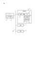
- FIG. 1 Schematic configuration diagram of a control system according to Embodiment 1 of the present disclosure
- Block diagram showing the hardware configuration of the control system according to Embodiment 1
- Block diagram showing the functional configuration of a control device according to Embodiment 1
- a diagram showing an example of information stored in the device information storage unit according to Embodiment 1.
- the control device controls a device by transmitting control information for controlling the device to the device based on a static address unique to the device in a network to which the device belongs.
- This control device includes a table storage unit that stores table information that associates dynamic addresses and static addresses assigned to devices in a network to which the devices belong, and a table storage unit that stores table information that associates dynamic addresses and static addresses assigned to devices, and a table storage unit that stores static addresses of devices based on the table information.
- a static address identification unit that specifies a static address, a device message transmission unit that sends a device message to the device based on the specified static address, and a combination of a dynamic address and a static address that are not included in the table information.
- a static address acquisition unit that acquires static address information and adds it to table information by transmitting static address request information that requests transmission of static address information indicating a static address to a corresponding device; , is provided.
- the control device 1 includes a CPU (Central Processing Unit) 101, a main storage section 102, an auxiliary storage section 103, a communication section 107, and a bus 109 that connects each section.
- the main storage unit 102 is a volatile memory such as RAM (Random Access Memory), and is used as a work area for the CPU 101.
- the auxiliary storage unit 103 includes a nonvolatile memory such as a semiconductor memory, functions as a ROM (Read Only Memory), and stores programs for realizing various functions of the control device 1 .
- the communication unit 107 includes, for example, a wireless module, and performs wireless communication with the device 3 and the router 8.
- the wireless module includes a signal generation circuit that generates a wireless signal and an antenna, and communicates using, for example, a data link layer communication protocol of the IEEE802.11 series.
- the CPU 101 loads the program stored in the auxiliary storage unit 103 into the main storage unit 102 and executes it, thereby controlling the device message acquisition unit 111, message type determination unit 112, and device control, as shown in FIG. 113 , a MAC address identifying unit 114 , a MAC address acquiring unit 115 , a device message transmitting unit 116 , and a device information updating unit 117 .
- the auxiliary storage section 103 shown in FIG. 2 includes an ARP table storage section 131, a device information storage section 132, and a device status storage section 133, as shown in FIG.
- the device message acquisition unit 111 Upon acquiring the device message transmitted from the device 3, the device message acquisition unit 111 notifies the message type determination unit 112 of the acquired device message.
- This device message includes update notification information that notifies that a network update event has occurred in which the state of the network NW1 to which the device 3 is connected has occurred.
- This network update event occurs when a new IP address is assigned to the device 3 by the DHCP function unit 811 of the router 8 due to the device 3 being newly connected to the network NW1, or when the IP address of the device 3 has expired. This occurs when the IP address of the device 3 is updated by the DHCP function unit 811.
- the device message also includes device status information including parameter information indicating the status of the device 3, and model information and identification number information of the device 3.
- the device control unit 113 generates control information based on at least one of the model information and device identification information corresponding to the device 3 to be controlled stored in the device information storage unit 132.
- the device control unit 113 determines whether or not the control details of the device 3 need to be updated, based on the device status information of each device 3 stored in the device status storage unit 133.
- the device control unit 113 determines that it is necessary to update the control content of the device 3, it generates control information corresponding to the updated device control content, and transmits the generated control information to the destination of the control information.
- the device message transmission unit 116 is notified along with IP address information indicating the IP address assigned to the device 3 and MAC address information indicating the MAC address.
- the MAC address specifying unit 114 When the MAC address specifying unit 114 is notified of the IP address information of the device 3 to which the control information is transmitted from the device control unit 113, the MAC address specifying unit 114 refers to the ARP table information stored in the ARP table storage unit 131 and identifies the notified IP address. Identify the MAC address corresponding to the IP address indicated by the address information. Then, the MAC address specifying unit 114 notifies the device message transmitting unit 116 of MAC address information indicating the specified MAC address.
- the MAC address acquisition unit 115 When the MAC address acquisition unit 115 is notified of the MAC address acquisition request information from the MAC address identification unit 114, the MAC address acquisition unit 115 broadcasts ARP request information to the device 3, thereby identifying the IP address and MAC address that are not included in the ARP table information.
- This is a static address acquisition unit that acquires ARP reply information from the device 3 corresponding to the combination.
- the ARP request information is static address request information that requests the device 3 to transmit ARP reply information including the MAC address information of the device 3.
- the MAC address acquisition unit 115 acquires the ARP reply information, it extracts the MAC address information included in the acquired ARP reply information, and converts the extracted MAC address information into the IP address of the device 3 that is the source of the ARP reply information. It is added to the ARP table information in association with the information. Furthermore, the MAC address acquisition unit 115 notifies the device information update unit 117 of the extracted MAC address information.
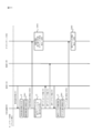
- Step S6 when the device 3A that is the source of the update notification information acquires ARP request information, ARP reply information including the MAC address information of the device 3A is transmitted from the device 3A to the control device 1 in response.
- the control device 1 upon acquiring the ARP reply information, extracts the MAC address information of the device 3A that is the transmission source of the update notification information included in the acquired ARP reply information, and stores the ARP table using the extracted MAC address information.
- the ARP table information stored in the unit 131 is updated (step S7).
- control device 1 correlates the model information and identification number information of the device 3A included in the acquired update notification information, the IP address information of the sender of the update notification information, and the extracted MAC address information. and stored in the device information storage section 132 (step S8).
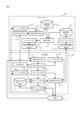
- step S101 determines whether the device message transmitted from the device 3 has been acquired.
- step S101: No determines that the device message has not been acquired
- step S110 which will be described later
- step S101: Yes determines whether the acquired device message is the above-mentioned update notification information.
- step S103 if the MAC address specifying unit 114 determines that a combination of the IP address and MAC address of the device 3 that is the transmission source of the update notification information exists (step S103: Yes), the process of step S110, which will be described later, is executed. .
- the MAC address acquiring unit 115 determines that the ARP request information is broadcasted (step S104). Thereby, the MAC address acquisition unit 115 acquires ARP reply information from the device 3 corresponding to the combination of the IP address and MAC address that are not included in the ARP table information (step S105).
- step S108 determines whether the device message is device status information. If the message type determination unit 112 determines that the device message is not device status information (step S108: No), the process of step S110, which will be described later, is executed. On the other hand, if the message type determination unit 112 determines that the device message is device status information (step S108: Yes), the message type determination unit 112 stores the device status information in the device status storage unit 133 (step S109). Next, the device control unit 113 refers to the device status information stored in the device status storage unit 133 and determines whether it is necessary to update the control details of the device 3 (step S110).
- step S101 determines that there is no need to update the control details of the device 3 (step S110: No).
- the device control unit 113 determines that it is necessary to update the control details of the device 3 (step S110: Yes)
- the device control unit 113 generates control information for updating the control details of the device 3 based on the device status information.
- the device message transmitting unit 116 transmits the control information to the device 3 based on the MAC address information of the device 3 to which the control information is to be transmitted, which is stored in the device information storage unit 132 (step S111). After that, the process of step S101 is executed again.
- the MAC address acquisition unit 115 generates ARP table information that associates the IP address given to the device 3 with the MAC address unique to the device 3.
- ARP request information By transmitting ARP request information to a device 3 corresponding to a combination of an IP address and a MAC address that is not included in , MAC address information is acquired and added to the ARP table information.
- the device 3 to be controlled can be appropriately managed using the MAC address unique to the device 3.
- a cloud server In the control system according to the present embodiment, a cloud server generates control information for controlling devices and transmits the generated control information to a control device via a wide area network, and the control device transmits control information acquired from the server to the devices.
- This embodiment differs from the first embodiment in that the device is controlled by sending data to the device based on a static address unique to the device in the local network to which it belongs.
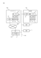
- the control system includes a cloud server 2002, a control device 2001 that controls the operation of the device 3 by transmitting control information acquired from the cloud server 2002 to the device 3, Equipped with.
- NW22 such as the Internet
- BBR broadband router
- the control device 2001 has the same hardware configuration as the control device 1 described in the first embodiment.
- the same components as in Embodiment 1 are given the same reference numerals as in FIG. 2.
- the CPU 101 loads the program stored in the auxiliary storage unit 103 into the main storage unit 102 and executes the program, so that the device message acquisition unit 2111, the message type determination unit 2112, and the non-capsule message acquisition unit 2111, the message type determination unit 2112, and the non-capsule It functions as an encoding unit 2117, a MAC address identification unit 114, a MAC address acquisition unit 2115, a device message transmission unit 2116, an address notification unit 2118, an update notification unit 2119, and an encapsulation unit 2120.
- FIG. 9 the same components as in Embodiment 1 are given the same reference numerals as in FIG. 3.
- the device message acquisition unit 2111 Upon acquiring the device message transmitted from the device 3 or the device message transmitted from the cloud server 2002 to the control device 2001, the device message acquisition unit 2111 notifies the message type determination unit 2112 of the acquired device message.
- the message type determination unit 2112 determines whether the device message acquired by the device message acquisition unit 2111 is update notification information that notifies the assignment of a new IP address to the device 3.
- the message type determination unit 2112 determines that the acquired device message is update notification information, it notifies the MAC address identification unit 114 of IP address information indicating the IP address of the device 3 that is the source of the update notification information.
- the update notification unit 2119 generates device information notification information including the model information, identification number information, and IP address information of the device 3 notified from the message type determination unit 2112, and transmits it to the cloud server 2002.
- the decapsulation unit 2117 When the decapsulation unit 2117 is notified of the encapsulated control information or update notification information from the message type determination unit 2112, the decapsulation unit 2117 removes the header information from the encapsulated control information or update notification information, and then decapsulates the encapsulated control information or update notification information. , the MAC address information and control information or update notification information of the device 3 to which the control information is transmitted are extracted, and the extracted MAC address information and control information or update notification information are notified to the device message transmission unit 2116. do.
- the MAC address acquisition unit 2115 When the MAC address acquisition unit 2115 is notified of the MAC address acquisition request information from the MAC address identification unit 114, the MAC address acquisition unit 2115 broadcasts ARP request information to the device 3, thereby identifying the IP address and MAC address that are not included in the ARP table information. ARP reply information is acquired from the device 3 corresponding to the combination. When the MAC address acquisition unit 2115 acquires the ARP reply information, it extracts the MAC address information included in the acquired ARP reply information, and notifies the address notification unit 2118 of the extracted MAC address information.
- the address notification unit 2118 extracts the MAC address information of the device 3 that is the source of the ARP reply information from the ARP reply information notified from the MAC address acquisition unit 2115, and generates address notification information including the extracted MAC address information. Send to cloud server 2002.
- the encapsulation unit 2120 When the encapsulation unit 2120 is notified of the device status information from the message type determination unit 2112, the encapsulation unit 2120 adds header information for specifying the cloud server 2002 as the destination to the notified device status information, thereby converting it into status notification information. is generated and notified to the device message transmission unit 2116.
- the device message transmitter 2116 transmits the control information or update notification information extracted by the decapsulator 2117 to the destination device 3 based on the MAC address information of the device 3 extracted by the decapsulator 2117. do. Furthermore, when the device message transmitting section 2116 is notified of the encapsulated device status information from the encapsulating section 2120, the device message transmitting section 2116 transmits the notified device status information to the cloud server 2002 based on the header information.
- the cloud server 2002 includes a CPU 201, a main storage section 202, an auxiliary storage section 203, a communication section 206, and a bus 209 that connects each section.
- the CPU 201 loads the program stored in the auxiliary storage unit 203 into the main storage unit 202 and executes it, thereby controlling the encapsulation unit 2211, the encapsulated message transmission unit 2212, and the device control, as shown in FIG. 2213 , update notification acquisition section 2214 , address acquisition section 2218 , device information update section 2217 , encapsulated message acquisition section 2215 , and non-encapsulation section 2216 .
- the device information storage unit 2232 associates the MAC address information of the plurality of devices 3 connected to the local network NW21 with the MAC address information of the control device 2001 connected to the local network NW21. memorize it. Furthermore, the device information storage unit 2232 stores a combination of IP address information, model information, and identification number information of each of the plurality of devices 3 in association with the MAC address information of the device 3 for each MAC address information of the control device 2001. are doing.
- the device status storage unit 2233 stores the above-mentioned parameter information of each device 3 in association with the device type information and identification number information of the device 3.
- the update notification acquisition unit 2214 Upon acquiring the device information notification information transmitted from the control device 2001, the update notification acquisition unit 2214 extracts the model information, identification number information, and IP address information of the device 3 included in the acquired device information notification information, and obtains the device information. The update unit 2217 is notified.
- the address acquisition unit 2218 acquires the address notification information transmitted from the control device 2001, the address acquisition unit 2218 extracts the MAC address information of the device 3 included in the acquired address notification information and notifies the device information update unit 2217.
- the device information update section 2217 converts the notified information into the MAC address notified from the address acquisition section 2218. It is stored in the device information storage unit 2232 in association with the information.
- the encapsulated message acquisition unit 2215 Upon acquiring the device status information transmitted from the control device 2001, the encapsulated message acquisition unit 2215 notifies the decapsulation unit 2216 of the acquired device status information.
- the decapsulation unit 2216 extracts the parameter information and the model information and identification number information of the device 3 included in the device status information notified from the encapsulated message acquisition unit 2215, and extracts the extracted parameter information and the model information of the device 3. and identification number information are stored in the device status storage unit 2233 in association with each other.
- the device control unit 2213 determines whether it is necessary to update the control details of the device 3 based on the device status information of each device 3 stored in the device status storage unit 2233. When the device control unit 2213 determines that it is necessary to update the control details of the device 3, the device control unit 2213 updates at least one of the model information and device identification information corresponding to the device 3 to be controlled stored in the device information storage unit 2232. Based on this, control information corresponding to the updated device control details is generated. Then, the device control unit 2213 notifies the encapsulation unit 2211 of the generated control information together with the IP address information and MAC address information of the device 3 to which the control information is transmitted, which is stored in the device information storage unit 2232.
- the encapsulation unit 2211 When the encapsulation unit 2211 is notified of the control information, the IP address information and the MAC address information of the device 3 from the device control unit 2213, the encapsulation unit 2211 adds header information for specifying the control device 2001 as the transmission destination to the notified control information. By adding and encapsulating the control notification information, control notification information is generated and notified to the encapsulated message transmission unit 2212. The encapsulated message transmitting unit 2212 transmits the notified control notification information to the control device 2001.
- the control device 2001 upon acquiring the ARP reply information, extracts the MAC address information of the device 3A that is the transmission source of the update notification information included in the acquired ARP reply information, and stores the ARP table using the extracted MAC address information.
- the ARP table information stored in the unit 131 is updated (step S7).
- the control device 2001 generates address notification information including the extracted MAC address information (step S2004), and the generated address notification information is transmitted from the control device 2001 to the cloud server 2002 (step S2005).
- the cloud server 2002 upon acquiring the address notification information, extracts the MAC address information included in the acquired address notification information, and combines the extracted MAC address information with the model information, identification number information, and IP address information of the device 3A. is stored in the device information storage unit 2232 in association with (step S2006).
- the cloud server 2002 determines that the control details of the device 3A need to be updated based on the device status information stored in the device status storage unit 2233 (step S2010).
- the cloud server 2002 generates control information corresponding to the updated device control content, adds header information for transmission to the control device 2001 to the generated control information, and encapsulates the generated control information (step S2011).
- the encapsulated control information is transmitted from the cloud server 2002 to the control device 2001 (step S2012).
- the control device 2001 upon acquiring the encapsulated control information, the control device 2001 decapsulates the control information by removing the header information of the acquired control information (step S2013).
- the non-encapsulated control information is transmitted from the control device 2001 to the device 3A based on the MAC address indicated by the MAC address information of the device 3A (step S14).
- the device 3A starts operating based on the acquired control information (step S15).
- IP address information is notified to the update notification unit 2119. Then, the update notification unit 2119 generates device information notification information including the model information, identification number information, and IP address information of the device 3 notified from the message type determination unit 2112, and transmits it to the cloud server 2002 (step S2101). .
- step S104 the MAC address identification unit 114 refers to the ARP table information stored in the ARP table storage unit 131, and determines whether a combination of the IP address and MAC address of the device 3 that is the source of the update notification information exists. Suppose that it is determined not to do so (step S104: No).
- the address notification unit 2118 acquires the MAC address information of the device 3 that is the source of the ARP reply information from the ARP reply information notified from the MAC address acquisition unit 2115. , generates address notification information including the extracted MAC address information, and sends it to the cloud server 2002 (step S2102).
- step S102 determines whether the device message is device status information (step S108).
- step S108 determines whether the device message is device status information (step S108: No)
- the process of step 2104 which will be described later, is executed.
- step S108: Yes determines that the device message is device status information (step S108: Yes)
- the encapsulating unit 2120 adds header information for transmitting to the cloud server 2002 to the device status information and encapsulates it, and the device message transmitting unit 2116 transmits the encapsulated device status information to the cloud server 2002. (Step S2103).
- the message type determination unit 2112 determines whether the device message is encapsulated control information (step S2104). Here, if the message type determination unit 2112 determines that the device message is not encapsulated control information (step S2104: No), the process of step S101 is executed again. On the other hand, if the message type determining unit 2112 determines that the device message is encapsulated control information (step S2104: Yes), it notifies the non-encapsulating unit 2117 of the control information. Then, the decapsulation unit 2117 removes the header information from the encapsulated control information, decapsulates it, extracts the MAC address information and control information of the device 3 that is the destination of the control information, and sends the device message. The unit 2116 transmits control information to the device 3 based on the extracted MAC address information (step S2105). Next, the process of step S101 is executed again.
- the cloud server 2002 includes the device information storage section 2232, the device status storage section 2233, and the device control section 2213, thereby providing a functional configuration of the control device 2001. can be simplified. Therefore, the processing load on the control device 2001 can be reduced.
- the update notification information may be a message that conforms to a standard other than the EchonetLite (registered trademark) standard.
- the MAC address acquisition units 115 and 2115 may broadcast ARP request information to the device 3 by executing a process of transmitting a so-called dummy device message to the device 3. good.
- various functions of the control device 1, 2001 and cloud server 2002 may be realized by software, firmware, or a combination of software and firmware.
- the software or firmware is written as a program, and the program is stored on a computer-readable disk such as a flexible disk, CD-ROM (Compact Disc Read Only Memory), DVD (Digital Versatile Disc), MO (Magneto-Optical Disc), etc.
- a computer-readable disk such as a flexible disk, CD-ROM (Compact Disc Read Only Memory), DVD (Digital Versatile Disc), MO (Magneto-Optical Disc), etc.
- each program may be posted on a bulletin board system (BBS) on a communication network and distributed via the network.
- BSS bulletin board system
- the above-described processes may be executed by starting these programs and executing them under the control of the OS in the same way as other application programs.
- the present disclosure is suitable as a control system including a HEMS installed in a residence.
Landscapes
- Engineering & Computer Science (AREA)
- Computer Networks & Wireless Communication (AREA)
- Signal Processing (AREA)
- Small-Scale Networks (AREA)
- Data Exchanges In Wide-Area Networks (AREA)
- Automation & Control Theory (AREA)
Priority Applications (5)
| Application Number | Priority Date | Filing Date | Title |
|---|---|---|---|
| CN202280096951.6A CN119404476A (zh) | 2022-06-22 | 2022-06-22 | 控制装置、控制系统、控制方法以及程序 |
| US18/857,504 US20250274305A1 (en) | 2022-06-22 | 2022-06-22 | Control device, control system, control method, and recording medium |
| DE112022007408.6T DE112022007408T5 (de) | 2022-06-22 | 2022-06-22 | Steuerungsapparat, steuerungssystem, steuerungsverfahren und programm |
| JP2022571883A JP7258255B1 (ja) | 2022-06-22 | 2022-06-22 | 制御装置、制御システム、制御方法およびプログラム |
| PCT/JP2022/024921 WO2023248382A1 (ja) | 2022-06-22 | 2022-06-22 | 制御装置、制御システム、制御方法およびプログラム |
Applications Claiming Priority (1)
| Application Number | Priority Date | Filing Date | Title |
|---|---|---|---|
| PCT/JP2022/024921 WO2023248382A1 (ja) | 2022-06-22 | 2022-06-22 | 制御装置、制御システム、制御方法およびプログラム |
Publications (1)
| Publication Number | Publication Date |
|---|---|
| WO2023248382A1 true WO2023248382A1 (ja) | 2023-12-28 |
Family
ID=85980427
Family Applications (1)
| Application Number | Title | Priority Date | Filing Date |
|---|---|---|---|
| PCT/JP2022/024921 Ceased WO2023248382A1 (ja) | 2022-06-22 | 2022-06-22 | 制御装置、制御システム、制御方法およびプログラム |
Country Status (5)
| Country | Link |
|---|---|
| US (1) | US20250274305A1 (https=) |
| JP (1) | JP7258255B1 (https=) |
| CN (1) | CN119404476A (https=) |
| DE (1) | DE112022007408T5 (https=) |
| WO (1) | WO2023248382A1 (https=) |
Cited By (1)
| Publication number | Priority date | Publication date | Assignee | Title |
|---|---|---|---|---|
| WO2026078911A1 (ja) * | 2024-10-11 | 2026-04-16 | 三菱電機株式会社 | 制御システム、制御装置、制御方法およびプログラム |
Citations (5)
| Publication number | Priority date | Publication date | Assignee | Title |
|---|---|---|---|---|
| JP2003023445A (ja) * | 2001-07-09 | 2003-01-24 | Mega Chips Corp | カメラサーバー及び映像送信システム |
| JP2014110603A (ja) * | 2012-12-04 | 2014-06-12 | Canon Inc | 通信装置、通信装置の制御方法、及びプログラム |
| JP2018081416A (ja) * | 2016-11-15 | 2018-05-24 | キヤノン株式会社 | 情報処理装置、情報処理装置の制御方法、及びプログラム |
| JP2021022830A (ja) * | 2019-07-26 | 2021-02-18 | エヌ・ティ・ティ・コムウェア株式会社 | 通信装置、通信システム、通信方法、およびプログラム |
| JP6984076B1 (ja) * | 2020-10-06 | 2021-12-17 | 三菱電機株式会社 | 制御システム、サーバ、端末装置、制御装置、通信制御方法およびプログラム |
Family Cites Families (5)
| Publication number | Priority date | Publication date | Assignee | Title |
|---|---|---|---|---|
| JP5952416B2 (ja) * | 2012-09-27 | 2016-07-13 | 京セラ株式会社 | 管理方法、制御装置及び通信処理デバイス |
| JP6085962B2 (ja) * | 2012-12-13 | 2017-03-01 | 東芝ライテック株式会社 | 管理装置及びアドレス管理方法 |
| US20140278248A1 (en) * | 2013-03-18 | 2014-09-18 | Sharp Laboratories Of America. Inc. | Method and System for Facilitating Enterprise Appliance Administration Based on Detected Power Anomalies |
| WO2021070914A1 (ja) * | 2019-10-09 | 2021-04-15 | パナソニック インテレクチュアル プロパティ コーポレーション オブ アメリカ | 機器監視方法、機器監視装置、及びプログラム |
| US12348517B2 (en) * | 2020-11-02 | 2025-07-01 | Mitsubishi Electric Corporation | Control system, control apparatus, device controlling method and recording medium |
-
2022
- 2022-06-22 CN CN202280096951.6A patent/CN119404476A/zh active Pending
- 2022-06-22 JP JP2022571883A patent/JP7258255B1/ja active Active
- 2022-06-22 DE DE112022007408.6T patent/DE112022007408T5/de active Pending
- 2022-06-22 WO PCT/JP2022/024921 patent/WO2023248382A1/ja not_active Ceased
- 2022-06-22 US US18/857,504 patent/US20250274305A1/en active Pending
Patent Citations (5)
| Publication number | Priority date | Publication date | Assignee | Title |
|---|---|---|---|---|
| JP2003023445A (ja) * | 2001-07-09 | 2003-01-24 | Mega Chips Corp | カメラサーバー及び映像送信システム |
| JP2014110603A (ja) * | 2012-12-04 | 2014-06-12 | Canon Inc | 通信装置、通信装置の制御方法、及びプログラム |
| JP2018081416A (ja) * | 2016-11-15 | 2018-05-24 | キヤノン株式会社 | 情報処理装置、情報処理装置の制御方法、及びプログラム |
| JP2021022830A (ja) * | 2019-07-26 | 2021-02-18 | エヌ・ティ・ティ・コムウェア株式会社 | 通信装置、通信システム、通信方法、およびプログラム |
| JP6984076B1 (ja) * | 2020-10-06 | 2021-12-17 | 三菱電機株式会社 | 制御システム、サーバ、端末装置、制御装置、通信制御方法およびプログラム |
Cited By (1)
| Publication number | Priority date | Publication date | Assignee | Title |
|---|---|---|---|---|
| WO2026078911A1 (ja) * | 2024-10-11 | 2026-04-16 | 三菱電機株式会社 | 制御システム、制御装置、制御方法およびプログラム |
Also Published As
| Publication number | Publication date |
|---|---|
| JP7258255B1 (ja) | 2023-04-14 |
| DE112022007408T5 (de) | 2025-04-17 |
| JPWO2023248382A1 (https=) | 2023-12-28 |
| CN119404476A (zh) | 2025-02-07 |
| US20250274305A1 (en) | 2025-08-28 |
Similar Documents
| Publication | Publication Date | Title |
|---|---|---|
| US9866522B2 (en) | Method to control dynamic host configuration protocol pool exhaustion in dynamic network environments | |
| US20080028071A1 (en) | Communication load reducing method and computer system | |
| KR102074916B1 (ko) | Rpl 기반 분산 mqtt 브로커 구조 | |
| US9641417B2 (en) | Proactive detection of host status in a communications network | |
| US9756148B2 (en) | Dynamic host configuration protocol release on behalf of a user | |
| KR100483022B1 (ko) | 위치 관리 서버와 이를 구비한 이더넷 기반의 무선랜 분배시스템 및 그 구현 방법 | |
| US20110219126A1 (en) | Mobile terminal, forwarding intermediate node and mobile communications system | |
| US11855894B2 (en) | Control system, server, terminal device, control device, communication control method, and recording medium | |
| CN111866201A (zh) | IPv6组播地址的生成方法和装置 | |
| KR20120015358A (ko) | 동적 호스트 구성 프로토콜 버전 6 서버의 아이피 어드레스 획득 방법, 동적 호스트 구성 프로토콜 버전 6 서버 및 동적 호스트 구성 프로토콜 버전 6 통신 시스템 | |
| CN103036794A (zh) | 一种报文的学习方法、装置和系统 | |
| US7760666B2 (en) | Method of generating and managing connection identifiers for supporting multicast for each group in IPv6-based wireless network and network interface using the method | |
| JP7258255B1 (ja) | 制御装置、制御システム、制御方法およびプログラム | |
| CN111083055B (zh) | 一种客户端设备管理方法、装置、路由器及存储介质 | |
| JP2024523867A (ja) | ワイヤレス通信ネットワークのための構成システム | |
| JP7325682B1 (ja) | 通信システム、通信制御装置、サーバ、通信制御方法およびプログラム | |
| JP5480719B2 (ja) | 端末装置、プレフィックス配布装置、IPv6アドレス生成システム、及びIPv6アドレス生成方法 | |
| CN108989173B (zh) | 一种报文传输的方法及装置 | |
| CN109842692B (zh) | 用于获得物理网络中主机信息的VxLAN交换机、系统和方法 | |
| JP7362001B1 (ja) | 制御装置、制御システム、制御方法およびプログラム | |
| CN117729180A (zh) | 一种dns动态更新方法及系统 | |
| JP7118307B1 (ja) | 通信システム、通信制御装置、通信制御方法およびプログラム | |
| WO2026078911A1 (ja) | 制御システム、制御装置、制御方法およびプログラム | |
| JP7433559B1 (ja) | 通信制御装置、通信システム、通信制御方法およびプログラム | |
| JP7612028B1 (ja) | 通信システム、通信制御方法およびプログラム |
Legal Events
| Date | Code | Title | Description |
|---|---|---|---|
| ENP | Entry into the national phase |
Ref document number: 2022571883 Country of ref document: JP Kind code of ref document: A |
|
| 121 | Ep: the epo has been informed by wipo that ep was designated in this application |
Ref document number: 22947943 Country of ref document: EP Kind code of ref document: A1 |
|
| WWE | Wipo information: entry into national phase |
Ref document number: 18857504 Country of ref document: US |
|
| WWE | Wipo information: entry into national phase |
Ref document number: 202280096951.6 Country of ref document: CN |
|
| WWE | Wipo information: entry into national phase |
Ref document number: 112022007408 Country of ref document: DE |
|
| WWP | Wipo information: published in national office |
Ref document number: 202280096951.6 Country of ref document: CN |
|
| WWP | Wipo information: published in national office |
Ref document number: 112022007408 Country of ref document: DE |
|
| 122 | Ep: pct application non-entry in european phase |
Ref document number: 22947943 Country of ref document: EP Kind code of ref document: A1 |
|
| WWP | Wipo information: published in national office |
Ref document number: 18857504 Country of ref document: US |