WO2023243448A1 - 二次流れ形成装置、固液分離装置及び固液分離システム - Google Patents
二次流れ形成装置、固液分離装置及び固液分離システム Download PDFInfo
- Publication number
- WO2023243448A1 WO2023243448A1 PCT/JP2023/020685 JP2023020685W WO2023243448A1 WO 2023243448 A1 WO2023243448 A1 WO 2023243448A1 JP 2023020685 W JP2023020685 W JP 2023020685W WO 2023243448 A1 WO2023243448 A1 WO 2023243448A1
- Authority
- WO
- WIPO (PCT)
- Prior art keywords
- flow path
- height
- fluid
- baffle plate
- solid
- Prior art date
- Legal status (The legal status is an assumption and is not a legal conclusion. Google has not performed a legal analysis and makes no representation as to the accuracy of the status listed.)
- Ceased
Links
Images




Classifications
-
- B—PERFORMING OPERATIONS; TRANSPORTING
- B01—PHYSICAL OR CHEMICAL PROCESSES OR APPARATUS IN GENERAL
- B01D—SEPARATION
- B01D43/00—Separating particles from liquids, or liquids from solids, otherwise than by sedimentation or filtration
-
- B—PERFORMING OPERATIONS; TRANSPORTING
- B03—SEPARATION OF SOLID MATERIALS USING LIQUIDS OR USING PNEUMATIC TABLES OR JIGS; MAGNETIC OR ELECTROSTATIC SEPARATION OF SOLID MATERIALS FROM SOLID MATERIALS OR FLUIDS; SEPARATION BY HIGH-VOLTAGE ELECTRIC FIELDS
- B03B—SEPARATING SOLID MATERIALS USING LIQUIDS OR USING PNEUMATIC TABLES OR JIGS
- B03B5/00—Washing granular, powdered or lumpy materials; Wet separating
-
- F—MECHANICAL ENGINEERING; LIGHTING; HEATING; WEAPONS; BLASTING
- F15—FLUID-PRESSURE ACTUATORS; HYDRAULICS OR PNEUMATICS IN GENERAL
- F15D—FLUID DYNAMICS, i.e. METHODS OR MEANS FOR INFLUENCING THE FLOW OF GASES OR LIQUIDS
- F15D1/00—Influencing flow of fluids
- F15D1/02—Influencing flow of fluids in pipes or conduits
Definitions
- the present disclosure relates to a secondary flow forming device, a solid-liquid separation device, and a solid-liquid separation system.
- solid-liquid separation techniques include centrifugation, membrane separation, sedimentation separation, and the like.
- solid-liquid separation technology is also applied to microfluidic devices having microchannels whose cross-sectional sizes are defined on the scale of mm or ⁇ m.
- Patent Document 1 discloses a technology related to a liquid sending device that sends liquid to a microchannel and performs solid-liquid separation by sedimentation.
- a pattern is formed on the inner wall or partition of the microchannel to generate an upward flow in the vertical direction at the center of the cross section of the microchannel. This pattern generates a flow in the opposite direction to the displacement flow that occurs as the solid particles settle, thereby canceling out the displacement flow and, as a result, contributing to obtaining a stable sedimentation rate.
- solid-liquid separation technology is also known that applies the tubular pinch effect, in which solid particles are concentrated at a specific position in a flow channel due to the lift or drag force that solid particles receive from the fluid and the inner wall of the flow channel.
- the tubular pinch effect in which solid particles are concentrated at a specific position in a flow channel due to the lift or drag force that solid particles receive from the fluid and the inner wall of the flow channel.
- a particle concentration region with a ring-shaped cross section is formed in the channel.
- the tubular pinch effect affects the left and right ends of the channel in the span direction, there is a region in the center of the channel where the tubular pinch effect does not affect. It is possible. Therefore, it is conceivable to expand the range of the tubular pinch effect by forming a secondary flow in the cross-sectional direction in a channel having a rectangular cross-section.
- Patent Document 1 Even if the patterns disclosed in Patent Document 1 are applied as obstacles, for example, these patterns are applied to a liquid feeding device that performs solid-liquid separation by sedimentation. Therefore, when performing solid-liquid separation using the tubular pinch effect, it is not always possible to generate the desired secondary flow.
- an object of the present disclosure is to provide a secondary flow forming device, a solid-liquid separation device, and a solid-liquid separation system that stably form a secondary flow while simplifying the structure.
- One aspect of the present disclosure is a secondary flow forming device that causes a fluid in which solid particles are dispersed to flow through a flow path to form a secondary flow in a cross-sectional direction in the fluid, the flow path portion having a flow path. and a plurality of baffles formed in the flow path, the flow path having a rectangular cross section with an aspect ratio of the flow path width divided by the flow path height ranging from 3 to 100.
- the inner wall constituting the flow path includes a first wall and a second wall that face each other in a direction in which the height of the flow path is defined, and each of the plurality of baffle plates protrudes toward the first wall.
- the extending direction of the baffle plate is parallel to the second wall and is inclined at a constant angle with respect to the extending direction of the flow path.
- the height of the baffle plate may be half the height of the channel.
- the height of the baffle plate is lower than half of the channel height
- the inclination angle of the baffle plate is ⁇
- the channel width is w
- the channel height is h
- the pitch related to the arrangement of the baffle plate is
- the height of the baffle plate is higher than half of the channel height
- the inclination angle of the baffle plate is ⁇
- the channel width is w
- the channel height is h
- the pitch related to the arrangement of the baffle plate is
- the width of the baffle plate be w p
- the channel width be w
- the channel height be h
- the pitch related to the baffle plate arrangement be P i
- the number of baffle plates in an arbitrary cross section be m.
- the inclination angle of the baffle plate may be in a range of 1° or more and 45° or less. If the length of the baffle plate in the stretching direction is LP , the number of baffle plates installed is n, and the channel height is h, the following condition of equation (4) may be satisfied.
- the inner wall constituting the flow path includes a third wall and a fourth wall that face each other in the direction in which the flow path width is defined, and the length component of the baffle plate along the direction of the flow path width is
- the baffle plate may be shorter than the road width and may be in non-contact with the third wall and the fourth wall. Furthermore, the distance between the rearmost end of the baffle plate that is the most downstream among the plurality of baffle plates and the third or fourth wall to which the rearmost end is closest is 0, where w is the channel width. It may be in the range of .35w or more and 0.65w or less.
- Another aspect of the present disclosure is a solid-liquid separator that separates solid particles from a fluid in which the solid particles are dispersed, and includes a secondary flow forming device that forms a secondary flow in a cross-sectional direction in the fluid.
- the secondary flow forming device is the above-mentioned secondary flow forming device, and separates solid particles from the fluid while forming a secondary flow in the fluid.
- the solid-liquid separator described above includes a fluid outlet portion having at least three outlet passages that communicate with the downstream side of the flow passage of the secondary flow forming device, and the at least three outlet passages are arranged in a direction in which the width of the passage is defined. may diverge from each other.
- the inlet width of each of the two outlet channels located at both ends in the direction in which the channel width is defined is set to a size that is at least twice the channel height and 45% or less of the channel width. may be done.
- a solid-liquid separation system includes a solid-liquid separation device that separates solid particles from a fluid in which the solid particles are dispersed, a storage tank that stores the fluid, and a solid-liquid separation device that separates the solid particles from the storage tank.
- the solid-liquid separator includes a liquid sending section that sends fluid to the liquid sending section, and a control section that adjusts at least the flow rate or speed of the fluid by controlling the operation of the liquid sending section. be.
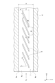
- FIG. 1 is a perspective view showing the configuration of a secondary flow forming device according to an embodiment.
- FIG. 2 is a partially cutaway sectional view of the flow path section corresponding to the II-II cross section in FIG.
- FIG. 3 is a schematic diagram for explaining the shape and arrangement of baffle plates.
- FIG. 4 is a fluid image showing the behavior of solid particles in a fluid that has passed through a plurality of baffles.
- FIG. 5 is a sectional view showing the configuration of a solid-liquid separator according to one embodiment.
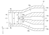
- FIG. 6A is a cross-sectional view showing the shape of a first example of a fluid outlet in a solid-liquid separator.
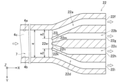
- FIG. 6B is a cross-sectional view showing the shape of a second example of a fluid outlet in the solid-liquid separator.
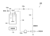
- FIG. 7A is a schematic diagram showing the configuration of a cell culture device according to one embodiment.
- FIG. 7B is a schematic diagram showing the configuration of a precipitation apparatus according to one embodiment.
- FIG. 1 is a perspective view showing the configuration of a secondary flow forming device 1 according to an embodiment.
- the secondary flow forming device 1 is used, for example, in a solid-liquid separation device that separates solid particles from a fluid in which the solid particles are dispersed.
- the secondary flow forming device 1 generates a secondary flow in the cross-sectional direction in the fluid flowing through the flow path 7, and concentrates solid particles at a specific position within the flow path 7 by the tubular pinch effect. .
- the fluid in which solid particles are dispersed refers to a liquid (particle dispersion) that includes a large number of solid particles.
- solid-liquid separation is based on the premise that solid particles of various particle sizes are dispersed in the fluid, and basically, solid particles of a specific particle size are selected from among them. Separation of particles.
- fine particles having a particle size in the range of 1 ⁇ m to 1 mm are assumed.
- the secondary flow forming device 1 includes a flow path portion 2 as a block body having a flow path 7 through which fluid is introduced and circulated.
- the flow path portion 2 may be a microfluidic device in which the cross section of the flow path 7 is defined on the scale of mm or ⁇ m.
- the direction of fluid introduction (IN) into the flow path 7 and the direction of fluid discharge from the flow path 7 (OUT) are indicated by white arrows.
- the flow path 7 extends linearly.
- linear means that the extending direction of the flow path 7 is along the X direction in the figure, which is an example of one direction.
- it is not limited to a strictly straight line, and some bending is allowed as long as the desired action on the fluid by the baffle plate 5, which will be explained in detail below, can be obtained.
- the cross section of the flow path 7 is rectangular.
- the rectangle referred to here is not a shape that is strictly interpreted geometrically, but allows for the existence of a slight bend in the sides themselves or a slight curved part in a continuous portion of the sides.
- the cross section of the flow path 7 is a YZ cross section.
- the long side of the flow path 7 in the cross section is along the Y direction, and is hereinafter defined as the flow path width w.
- the short side of the flow path 7 in the cross section is along the Z direction, and is hereinafter defined as the flow path height h.
- the channel height h is perpendicular to the channel width w on the cross section.
- the Y direction may be expressed as the channel width direction
- the Z direction may be expressed as the channel height direction.
- the Z direction is assumed to be a direction parallel to the vertical direction, and the Z direction may be appropriately expressed as "up” or "down”.
- the flow path section 2 is formed, for example, by overlapping two flat plates, the first flat plate 3 and the second flat plate 4, in the Z direction.
- the lower second flat plate 4 has three inner walls defining the shape of the flow path 7, namely, a first side wall 4a, a second side wall 4b, and a bottom wall 4c, as grooves on the upper surface side facing the first flat plate 3.
- the first side wall 4a and the second side wall 4b are side walls that face each other in the Y direction and correspond to the respective short sides in the cross section.
- the first flat plate 3 on the upper stage is a so-called lid, and is joined to the second flat plate 4 so as to cover the flow path 7 with its lower surface.
- the wall portion of the first flat plate 3 that faces the bottom wall 4c of the second flat plate 4 serves as the remaining inner wall that defines the shape of the flow path 7.
- This is the upper wall 3a.
- the top wall 3a and the bottom wall 4c are side walls that face each other in the Z direction and correspond to the respective long sides in the cross section.
- the first flat plate 3 is drawn with a chain double-dashed line in order to clearly show the overall shape of the flow path 7.
- the secondary flow forming device 1 has a plurality of baffle plates 5 in the flow path section 2.
- the baffle plate 5 in this embodiment is a protrusion that protrudes from the bottom wall 4c of the second flat plate 4 toward the lower surface of the first flat plate 3.
- the upper surface of the baffle plate 5 does not come into contact with the first flat plate 3.
- the plurality of baffle plates 5 have the same shape and are arranged in the flow path 7 with a certain regularity as will be explained in detail below.
- six baffle plates 5 are illustrated as a first plate 5a, a second plate 5b, a third plate 5c, a fourth plate 5d, a fifth plate 5e, and a sixth plate 5f.
- FIG. 1 six baffle plates 5 are illustrated as a first plate 5a, a second plate 5b, a third plate 5c, a fourth plate 5d, a fifth plate 5e, and a sixth plate 5f.
- the baffle plate 5 that intersects with the inlet or outlet of the secondary flow forming device 1 is, as a drawing example, a part that goes outward of the secondary flow forming device 1 from the intersecting position or the vicinity thereof. is represented by a shape that does not exist.
- FIG. 2 is a sectional view of a part of the secondary flow forming device 1 cut along a plane perpendicular to the X direction, which is the extending direction of the flow path 7, corresponding to the II-II cross section in FIG.
- FIG. 2 the state of the flow of the fluid flowing in the flow path 7 at the relevant cut plane is illustrated by vectors.
- FIG. 3 is a schematic diagram for explaining the shape of the baffle plates 5 and the arrangement relationship of the baffle plates 5, when the baffle plates 5 are viewed along the Z direction.
- FIG. 3 is expressed as a partial cross-sectional view in which a part of the flow path portion 2 is cut along an arbitrary XY plane.
- the baffle plate 5 is a rod-shaped portion whose extending direction is parallel to the bottom wall 4c along the XY plane and inclined at an inclination angle ⁇ with respect to the X direction. However, both ends of each baffle plate 5 may be cut out along the XZ plane. If the length of the baffle plate 5 in the stretching direction is the baffle plate length LP , then the length of the baffle plate 5 in the Y direction, which is the direction in which the channel width w is defined (hereinafter referred to as the "channel width direction"). The length component L Y is represented by L P sin ⁇ and is shorter than the channel width w. Further, the baffle plate 5 is not in contact with either the first side wall 4a or the second side wall 4b. In the flow path 7, n baffle plates 5 having such a shape are arranged along the X direction at equal intervals of a pitch P i .
- the shape of the cross section perpendicular to the extending direction of the baffle plate 5 is approximately rectangular.
- the height of the baffle plate 5 will be expressed as a baffle plate height hP
- the width of the baffle plate 5 will be expressed as a baffle plate width wp , respectively.
- the baffle plate height hP is set as follows, for example, based on the channel height h of the channel 7.
- the flow velocity of the fluid flowing through the flow path 7 is defined as follows.
- V 0 is the mainstream flow velocity of the fluid introduced into the flow path 7 along the X direction, which is the direction in which the flow path 7 extends.
- V 1 is the first flow velocity in the direction along the stretching direction of the baffle plate 5 .
- V 2 is the second flow velocity in the Y direction, which is the channel width direction, and is expressed by equation (5) using the mainstream velocity V 0 .
- the baffle plate height hP is half the height of the flow path height h, that is, 0.5h, the plurality of baffle plates 5 most efficiently direct the secondary flow. can be generated.
- equation (1) By substituting and rearranging equations (5) and (6) into equation (8), equation (1) already mentioned is derived.
- the baffle height hP is lower than 0.5h
- the baffle is The pitch P i related to the arrangement of the plates 5, the number n of baffle plates 5 installed, and the baffle plate height h P may be set.
- equation (2) By substituting equation (5) and equation (6) into equation (9) and sorting it out, equation (2) already mentioned is derived.
- the baffle plate height hP is higher than 0.5h
- the baffle is The pitch P i related to the arrangement of the plates 5, the number n of baffle plates 5 installed, and the baffle plate height h P may be set.
- the upper limit value of the baffle plate height h P is defined based on formula (2), and the lower limit value of the baffle plate height h P is determined based on formula (1). may be defined based on
- the baffle width wp is determined, for example, based on the condition that in order to reduce the pressure loss within the flow path 7, it is desirable that the blockage rate of the cross section of the flow path 7 is 0.5 or less. It is set as follows. The cross section of the channel 7 assuming that the baffle plate 5 does not exist is expressed as (channel width w x channel height h). Therefore, if the number of baffle plates 5 in a certain cross section is m, in order to satisfy the condition that the blockage rate is 0.5 or less, the upper limit value of the baffle plate width w p can be determined using the equation (3) given above. Just set it so that it satisfies. On the other hand, it is desirable that the lower limit of the baffle plate width wp be set as small as possible.
- the inclination angle ⁇ of the baffle plate 5 may be determined by determining a range defined by an upper limit value and a lower limit value based on equations (1) and (2), and may be set to a value included in the range. However, if the inclination angle ⁇ is too large, flow separation may occur, which may result in unintended secondary flow. On the other hand, from the viewpoint of similarly suppressing flow separation, it is desirable that the inclination angle ⁇ is as small as possible; however, if it is too small, the value of tan ⁇ becomes small, and as a result, the baffle plate 5 referred to in equation (1) etc. It may be necessary to set the pitch P i or the number n of baffle plates 5 to be large.
- the inclination angle ⁇ is at least 1° or more. Therefore, the inclination angle ⁇ is preferably in the range of 1° or more and 45° or less, and more preferably 1° or more and 30° or less.
- FIG. 4 is a fluid image showing the behavior of solid particles p in the fluid that has passed through the flow path 7. Note that the behavior of solid particles in the fluid while passing through the flow path 7 may also be similar to the behavior shown in FIG. 4 .
- the fluid image shown in FIG. 4 is obtained by photographing the fluid flowing through a part of the flow path 7 along the Z direction.
- the plurality of baffle plates 5 are arranged from the upstream side to the downstream side of the flow path 7 along the X direction.
- the approximate position of the baffle plate 5 with respect to the position in the flow path 7 where the fluid image was acquired is shown by a two-dot chain line adjacent to the fluid image.
- the solid particles p can be captured at least near the first side wall 4a or the second side wall 4b. Recognize.
- the particle concentration at the inlet region RIN of the channel 7 was 0.55 vol%.
- the particle concentration in the high concentration region R H where the solid particles p gathered on the outlet side of the flow path 7 was 1.33 vol %.
- the particle concentration in the low concentration region R L with few solid particles p was 0.11 vol %.
- the secondary flow forming device 1 moves the solid particles p not only in the vicinity of the first side wall 4a or the second side wall 4b but also in the flow path 7 as shown in FIG. It can also be trapped in the central region in the width direction of the channel.
- the baffle plate length LP is a condition for trapping the solid particles p in the central region of the flow path 7 in the width direction of the flow path.
- the solid particles p In order to trap the solid particles p in the central region in this way, it is necessary to produce a tubular pinch effect as an action of the plurality of baffles 5.
- the solid particles p In other words, the solid particles p must move along the baffles 5 to some extent. It is necessary to flow the distance. This distance needs to be at least 100 times the channel height h. Therefore, it is only necessary to satisfy the conditions of the equation (4) above using the baffle plate length L P , the number n of baffle plates installed, and the channel height h.
- the baffle plate 5 located on the most downstream side among the plurality of baffle plates 5 corresponds to the sixth plate 5f.
- the rearmost end be located as close to the center of the channel 7 in the channel width direction as possible.
- the distance e between the rearmost end of the baffle plate 5 that is the most downstream among the plurality of baffle plates 5 and the first side wall 4a or second side wall 4b to which the rearmost end is closest is determined by the flow path width. Assuming that w is in the range of 0.35w or more and 0.65w or less, it is desirable. Referring to FIG. 3, the distance e corresponds to the distance between the rearmost end of the baffle plate 5, which may correspond to the sixth plate 5f, and the first side wall 4a.
- the secondary flow forming device 1 is configured to cause a fluid in which solid particles p are dispersed to flow through a channel 7 to form a secondary flow in the cross-sectional direction of the fluid, and includes a channel section having the channel 7. 2, and a plurality of baffle plates 5 formed in the flow path section 2.
- the channel 7 has a rectangular cross section with an aspect ratio A R in the range of 3 to 100, which is the channel width w divided by the channel height h.
- the inner walls forming the flow path 7 include a first wall and a second wall that face each other in the direction in which the flow path height h is defined.
- Each of the plurality of baffle plates 5 is a rod-shaped portion arranged on the second wall so as to protrude toward the first wall.
- the direction in which each baffle plate 5 extends is parallel to the second wall and is inclined at a constant angle with respect to the direction in which the flow path 7 extends.
- the first wall corresponds to the upper wall 3a of the first flat plate 3 that constitutes a part of the flow path section 2, and the second wall constitutes another part of the flow path section 2. This corresponds to the bottom wall 4c of the second flat plate 4.
- the flow path 7 is defined as having a rectangular cross section with an aspect ratio AR in the range of 3 to 100. This causes a tubular pinch effect on the fluid flowing in the flow path 7, and the solid particles p dispersed in the fluid are removed from at least the first side walls, which are inner walls facing each other in the width direction of the flow path. 4a or near the second side wall 4b.
- the secondary flow forming device 1 is provided with a plurality of baffle plates 5, it is possible to form a secondary flow in the fluid flowing through the flow path 7.
- a secondary flow occurs, the solid particles p dispersed in the fluid are subjected to a drag force induced by the secondary flow.
- the separation efficiency can be improved compared to the case of separation.
- the shape and arrangement of the plurality of baffle plates 5 defined as above it is possible to suppress an increase in the blockage rate of the flow path 7 and, as a result, suppress pressure loss in the flow path 7.
- a secondary flow can be stably formed over a long distance in the main flow direction of the flow path 7.
- the secondary flow forming device 1 since the plurality of baffle plates 5 are positioned as a so-called passive type secondary flow forming mechanism that does not utilize external power, the secondary flow forming device 1 as a whole can have a simple structure.
- the secondary flow forming device 1 that stably forms a secondary flow while simplifying the structure.
- the height hP of the baffle plate 5 may be half of the channel height h.
- the plurality of baffle plates 5 can generate the secondary flow most efficiently.
- the height hP of the baffle plate 5 may be lower than half of the channel height h.
- the inclination angle of the baffle plate 5 is ⁇
- the channel width is w
- the channel height is h
- the pitch related to the arrangement of the baffle plate 5 is P i
- the number of baffle plates 5 installed is n.
- the height of the baffle plate 5 is hP .
- the pitch P i the number n of baffle plates 5 installed, and , the height hP of the baffle plate 5 may be set.
- the dimensions of each part can be set assuming in advance that the flow rate of the secondary flow will decrease proportionally as the baffle plate height hP becomes lower. It is possible to suppress a decrease in the generation efficiency of the next flow.
- the height hP of the baffle plate 5 may be higher than half of the channel height h.
- the inclination angle of the baffle plate 5 is ⁇
- the channel width is w
- the channel height is h
- the pitch related to the arrangement of the baffle plate 5 is P i
- the number of baffle plates 5 installed is n.
- the height of the baffle plate 5 is hP .
- the pitch P i the number n of baffle plates 5 installed, and , the height hP of the baffle plate 5 may be set.
- the flow rate of the secondary flow also decreases when the height h P of the baffle plate is higher than 0.5 h.
- the dimensions of each part can be set assuming in advance that the flow rate of the secondary flow will decrease proportionally as the baffle plate height hP increases. It is possible to suppress a decrease in the generation efficiency of the next flow.
- the width of the baffle plate 5 is w p
- the flow path width is w
- the flow path height is h
- the pitch related to the arrangement of the baffle plate 5 is P i
- the number of baffle plates 5 in an arbitrary cross section Let m be the height of the baffle plate 5, and let hP be the height of the baffle plate 5.
- the upper limit value of the width wp of the baffle plate 5 may satisfy the condition of the above equation (3).
- the condition that the blockage rate is 0.5 or less can be satisfied, and as a result, the pressure loss in the flow path 7 can be further reduced.
- the inclination angle ⁇ of the baffle plate 5 may be in the range of 1° or more and 45° or less.
- separation of the flow within the flow path 7 can be suppressed, and in turn, an increase in pressure loss within the flow path 7 can be suppressed.
- the length of the baffle plate 5 in the stretching direction is LP
- the number of installed baffle plates 5 is n
- the height of the flow path is h
- the solid particles p dispersed in the fluid can be simply captured in the vicinity of the first side wall 4a or the second side wall 4b, which are inner walls facing each other in the channel width direction. Instead, it can be captured in the central region of the flow path 7 in the width direction of the flow path.
- the inner wall forming the flow path 7 includes a third wall and a fourth wall that face each other in the direction in which the flow path width w is defined.
- the length component LY of the baffle plate 5 along the direction of the flow path width w is shorter than the flow path width w, and the baffle plate 5 is It may not be in contact with the wall.
- the third wall corresponds to the first side wall 4a of the second flat plate 4 that constitutes a part of the flow path section 2
- the fourth wall corresponds to the second side wall 4b of the second flat plate 4. Equivalent to.
- the flow in the width direction of the flow path can more easily circulate in the cross section of the flow path 7, so that the secondary flow can be generated more stably over a long distance in the main flow direction of the flow path 7.
- a flow can be formed.
- the distance e between the rearmost end of the baffle plate 5 that is the most downstream among the plurality of baffle plates 5 and the third or fourth wall to which the rearmost end is closest may be in the range of 0.35w or more and 0.65w or less, where w is the channel width.
- the solid particles p dispersed in the fluid can be simply captured in the vicinity of the first side wall 4a or the second side wall 4b, which are inner walls facing each other in the channel width direction. Instead, it can be captured in the central region of the flow path 7 in the width direction of the flow path.
- the plurality of baffle plates 5 are provided on the bottom wall 4c of the second flat plate 4, and protrude from the bottom wall 4c toward the top wall 3a of the first flat plate 3. That is, the first wall corresponds to the top wall 3a, and the second wall corresponds to the bottom wall 4c.
- the plurality of baffle plates 5 may be provided on the top wall 3a and protrude from the top wall 3a toward the bottom wall 4c. That is, the first wall may correspond to the bottom wall 4c, and the second wall may correspond to the top wall 3a.
- the plurality of baffle plates 5 may be provided on both the top wall 3a and the bottom wall 4c so as to face each other without contacting each other.
- the plurality of baffle plates 5 are arranged at a pitch P i of one value throughout the flow path 7 in the extending direction.
- the plurality of baffle plates 5 are arranged at pitches P i of a plurality of values throughout the extending direction of the flow path 7, that is, the values of the pitches P i are changed in the middle of the arrangement. It may be something that is done. However, if the value of the pitch P i is too small, the viscous resistance will increase, so it is desirable that the value of the pitch P i be set larger than the channel height h.
- the plurality of baffle plates 5 are provided at the center of the channel width w of the channel 7. That is, in the channel width direction, the distance from the baffle plate 5 to the first side wall 4a and the distance from the baffle plate 5 to the second side wall 4b are the same.
- the plurality of baffle plates 5 may be provided closer to the first side wall 4a than the second side wall 4b in the channel width direction, or conversely, the baffle plates 5 may be provided closer to the first side wall 4a than the second side wall 4b. It may be provided so as to be closer to the second side wall 4b than the side.
- the flow path portion 2 is constituted by a combination of two flat plates, the first flat plate 3 and the second flat plate 4, is illustrated.
- the flow path portion 2 may be integrally formed, for example, by using three-dimensional metal additive manufacturing technology.
- Solid-liquid separator Next, a solid-liquid separation device using the secondary flow forming device 1 will be explained.
- FIG. 5 is a schematic cross-sectional view showing the configuration of the solid-liquid separator 10 according to one embodiment.
- the overall configuration of the solid-liquid separation device 10 is drawn in accordance with the cross-sectional view of FIG. 3 used in the explanation regarding the secondary flow forming device 1.
- the solid-liquid separator 10 separates solid particles from a fluid in which solid particles are dispersed based on a desired standard, and leads out each fluid containing solid particles sorted based on the standard.
- the criterion here is, for example, the particle diameter of solid particles.
- the solid-liquid separation device 10 includes the secondary flow forming device 1 described above, a fluid introduction section 11, and a fluid outlet section 12.
- the fluid introduction section 11 is connected to the upstream side of the secondary flow forming device 1, and introduces fluid into the flow path 7 in accordance with the fluid introduction direction ("IN" in FIG. 1).
- the fluid introduction part 11 is, for example, a block body having a flow path 11a in accordance with the shape of the upstream side of the secondary flow forming device 1.
- the fluid introduction part 11 may be a part that is integrated with the secondary flow forming device 1 in advance.
- the fluid introduction section 11 may be manufactured separately from the secondary flow forming device 1 and then connected to the secondary flow forming device 1.
- the flow path 11a has a first inlet 11b that serves as a fluid introduction side, and a first outlet 11c that serves as a fluid outlet side.
- the first introduction port 11b communicates with a supply mechanism (not shown) that supplies fluid to the fluid introduction section 11.
- the number of first inlet ports 11b installed is one in this embodiment, but is not limited to this, and a plurality of first inlet ports 11b may be provided so as to individually introduce fluid into the same channel 11a from a plurality of supply mechanisms. Good too. That is, in the fluid introduction section 11, there is at least one first introduction port 11b.
- the first outlet 11c communicates with the second inlet 8a, which is the fluid inlet side of the flow path 7 of the secondary flow forming device 1. That is, the cross section of the flow path 11a at least at the first outlet 11c connected to the second inlet 8a has the same shape as the cross section of the flow path 7 of the secondary flow forming device 1.
- the fluid derivation unit 12 is connected to the downstream side of the secondary flow forming device 1, and after introducing the fluid from the flow path 7 in accordance with the fluid discharge direction (“OUT” in FIG. 1), the fluid is distributed to a plurality of portions and discharged to the outside. It is derived as follows.
- the fluid lead-out section 12 is, for example, a block body having at least three lead-out passages, matching the shape of the downstream side of the secondary flow forming device 1 .
- the fluid outlet portion 12 may be a portion integrated with the secondary flow forming device 1 in advance, as shown in FIG. 5 . Alternatively, the fluid outlet portion 12 may be manufactured separately from the secondary flow forming device 1 and then connected to the secondary flow forming device 1.
- the fluid derivation section 12 at least three derivation paths are set in advance for each fluid containing solid particles distributed in the flow path 7 of the secondary flow forming device 1.
- the solid particles p dispersed in the fluid are located near the first side wall 4a or the second side wall 4b, which are inner walls facing each other in the width direction of the flow path 7.
- the third introduction port 12d which communicates with the second outlet port 8b on the fluid outlet side of the flow path 7, branches into at least three outlet paths in the width direction of the flow path.
- the fluid lead-out section 12 has three lead-out paths: a first lead-out path 12a, a second lead-out path 12b, and a third lead-out path 12c.
- FIG. 6A is an enlarged cross-sectional view of the fluid outlet portion 12, which is partially extracted from the cross-sectional view of the solid-liquid separator 10 shown in FIG.
- the cross-sectional shapes of the first lead-out path 12a, the second lead-out path 12b, and the third lead-out path 12c are each rectangular, and regarding the shape of the opening of each part, the length along the Y direction is defined as ⁇ opening''. "width" and the length along the Z direction is "opening height.”
- the first outlet path 12a is a flow path intended to flow a fluid containing solid particles captured near the first side wall 4a in the flow path 7 of the secondary flow forming device 1.
- the opening on the fluid introduction side of the first outlet path 12a is the first branch port 12h, and faces the third introduction port 12d.
- the opening on the fluid outlet side of the first outlet path 12a is the first outlet 12e.
- the second outlet path 12b is a flow path intended to flow a fluid containing solid particles captured near the second side wall 4b in the flow path 7 of the secondary flow forming device 1.
- the opening on the fluid introduction side of the second outlet path 12b is the second branch port 12i, and faces the third introduction port 12d.
- the opening on the fluid outlet side of the second outlet path 12b is the third outlet 12g.
- the central region in the channel width direction in the channel 7 of the secondary flow forming device 1 is a region shown as a low concentration region R L in FIG.
- This flow path is designed to flow a fluid with a small content of particles p.
- the central region in the channel width direction of the channel 7 is a region shown as a high concentration region R H in FIG.
- This is a flow path designed to allow fluid to flow through it.
- the opening on the fluid introduction side of the third outlet path 12c is the third branch port 12j, and faces the third introduction port 12d.
- the opening on the fluid outlet side of the third outlet path 12c is the second outlet 12f.
- the entire cross section of the third inlet 12d has the same shape as the cross section of the flow path 7 of the secondary flow forming device 1.
- the first branch port 12h, the second branch port 12i, and the third branch port 12j are arranged along the Y direction in the figure corresponding to the flow path width direction.
- the branch port 12j and the second branch port 12i are arranged in this order.
- the opening width hereinafter referred to as "inlet width”
- the entrance width w1 of the first branch port 12h and the second branch port 12i is the same, and A case where the width is larger than the entrance width of the three-branch port 12j is illustrated.
- each of the first outlet path 12a, the second outlet path 12b, and the third outlet path 12c is the same as the channel height h of the channel 7 as a whole.
- the first discharge port 12e, the second discharge port 12f, and the third discharge port 12g are also lined up in that order along the Y direction.
- FIG. 6A illustrates a case where the opening width and opening height of each of the first discharge port 12e, the second discharge port 12f, and the third discharge port 12g are the same.
- the solid-liquid separator 10 may include a fluid outlet section 22 as a second example having four outlet paths instead of the fluid outlet section 12 as the first example.
- FIG. 6B is an enlarged cross-sectional view of the fluid outlet portion 22 drawn corresponding to FIG. 6A.
- the fluid lead-out section 22 has four lead-out paths: a first lead-out path 22a, a second lead-out path 22b, a third lead-out path 22c, and a fourth lead-out path 22d.
- the first outlet path 22a is a flow path designed to flow a fluid containing solid particles captured near the first side wall 4a in the flow path 7 of the secondary flow forming device 1.
- the opening on the fluid introduction side of the first outlet path 22a is the first branch port 22j, and faces the third introduction port 22e.
- the opening on the fluid outlet side of the first outlet path 22a is the first outlet 22f.
- the second outlet path 22b may be a flow path intended to flow a fluid containing solid particles captured in the central region in the width direction of the flow path in the flow path 7 of the secondary flow forming device 1.
- the second outlet path 22b may be a flow path intended to flow a fluid with a low content of solid particles p in the low concentration region RL .
- the opening on the fluid introduction side of the second outlet path 22b is the second branch port 22m, and faces the third introduction port 22e.
- the opening on the fluid outlet side of the second outlet path 22b is the second outlet 22g.
- the third outlet path 22c is a flow path assumed to be similar to the second outlet path 22b.
- the opening on the fluid introduction side of the third outlet path 22c is the third branch port 22n, and faces the third introduction port 22e.
- the opening on the fluid outlet side of the third outlet path 22c is the third outlet 22h.
- the fourth outlet path 22d is a flow path designed to flow a fluid containing solid particles captured near the second side wall 4b in the flow path 7 of the secondary flow forming device 1.
- the opening on the fluid introduction side of the fourth outlet path 22d is the fourth branch port 22k, and faces the third introduction port 22e.
- the opening on the fluid outlet side of the fourth outlet path 22d is the fourth outlet 22i.
- the entire cross section of the third inlet 22e has the same shape as the cross section of the flow path 7 of the secondary flow forming device 1.
- the first branch port 22j, the second branch port 22m, the third branch port 22n, and the fourth branch port 22k are arranged in that order along the Y direction in the figure corresponding to the channel width direction. line up.
- the inlet width w2 of the first branch port 22j and the fourth branch port 22k in the third introduction port 22e is the same and wider than the inlet widths of the second branch port 22m and the third branch port 22n.
- the example shows a large case.
- each of the first outlet path 22a, the second outlet path 22b, the third outlet path 22c, and the fourth outlet path 22d is the same as the channel height h of the channel 7 as a whole.
- the first discharge port 22f, the second discharge port 22g, the third discharge port 22h, and the fourth discharge port 22i are also lined up in that order along the Y direction.
- FIG. 6B illustrates a case where the opening width and opening height of each of the first discharge port 22f, the second discharge port 22g, the third discharge port 22h, and the fourth discharge port 22i are the same.
- the solid-liquid separation device 10 may include an intermediate flow path portion 13 between the secondary flow forming device 1 and the fluid outlet portion 12.
- the intermediate flow path portion 13 is a block body provided to match the shape of the flow path portion 2 of the secondary flow forming device 1.
- the intermediate flow path section 13 is not provided with a portion like the baffle plate 5 that the flow path section 2 has. Note that, as shown in FIG. 5, the intermediate flow path portion 13 may be a portion integrated with the secondary flow forming device 1 in advance. Alternatively, the intermediate flow path portion 13 may be manufactured separately from the secondary flow forming device 1 and then connected to the secondary flow forming device 1.
- the intermediate flow path section 13 has a flow path 13a whose cross section is the same as the cross section of the flow path 7 of the secondary flow forming device 1.
- the flow path 13a has a fourth inlet 13b that serves as a fluid introduction side, and a fourth outlet 13c that serves as a fluid outlet side.
- the fourth inlet 13b communicates with the second outlet 8b on the side of the secondary flow forming device 1
- the fourth outlet 13c communicates with the fluid outlet 12. It communicates with the third inlet 12d on the side. That is, the second outlet port 8b on the side of the secondary flow forming device 1 and the third inlet port 12d on the side of the fluid outlet section 12 communicate with each other via the channel 13a of the intermediate channel section 13.
- the solid-liquid separator 10 includes the intermediate flow path section 13
- the fluid that has passed through the flow path 7 of the secondary flow forming device 1 is prevented from tubular pinch in the flow path 13a of the intermediate flow path section 13. effect can be produced. Thereby, there is a possibility that the separation efficiency can be improved more than when using the secondary flow forming device 1 alone.
- the solid-liquid separator 10 separates solid particles from a fluid in which solid particles are dispersed, and includes a secondary flow forming device that forms a secondary flow in the cross-sectional direction of the fluid.
- the secondary flow forming device is the above-mentioned secondary flow forming device 1, which separates solid particles from the fluid while forming a secondary flow in the fluid.
- this solid-liquid separator 10 since it is equipped with the above-mentioned secondary flow forming device 1, it is possible to form a secondary flow stably while simplifying the structure. Separation efficiency can be improved by widening the range.
- the solid-liquid separation device 10 may include a fluid outlet portion having at least three outlet paths communicating with the downstream side of the flow path 7 of the secondary flow forming device 1.
- the at least three lead-out paths may diverge from each other in the direction in which the channel width w is defined.
- the at least three lead-out paths correspond to the first lead-out path 12a, the second lead-out path 12b, and the third lead-out path 12c.
- the at least three outlet paths include a first outlet path 22a, a second outlet path 22b, a third outlet path 22c, and a fourth outlet path. This corresponds to the road 22d.
- the fluid outlet section 12 and the like separate solid particles according to a desired standard in accordance with each position where solid particles are captured in the channel width direction in the channel 7 of the secondary flow forming device 1.
- Each fluid containing solid particles can be introduced into a desired outlet path.
- the inlet width of each of the two outlet channels located at both ends in the direction in which the channel width w is defined is at least twice the channel height h, and The dimensions may be set within a range of 45% or less.
- the entrance width here corresponds to the entrance width w1 of each of the first branch port 12h and the second branch port 12i, and according to the example of FIG. This corresponds to the entrance width w2 of each of the fourth branch ports 22k.
- the fluid containing the high concentration region RH and the fluid containing the low concentration region RL can be further separated. It can be efficiently branched and derived.
- the fluid introduction section 11, the fluid outlet section 12, or the intermediate flow path section 13 may each be configured by a combination of two flat plates, similarly to the flow path section 2 of the secondary flow forming device 1.
- the solid-liquid separation device 10 including the secondary flow forming device 1, the fluid introduction section 11, the fluid outlet section 12, and the intermediate flow path section 13 is integrally formed. may be done. By shaping the solid-liquid separator 10 in this manner, the solid-liquid separator 10 can be mass-produced at low cost.
- FIGS. 7A and 7B are schematic diagrams showing a configuration example of a solid-liquid separation system including the solid-liquid separation device 10 described above.
- FIG. 7A is a diagram showing a cell culture device (an animal cell continuous culture device) 100 as an example of the solid-liquid separation system according to the present embodiment.
- a culture solution is assumed to be the fluid in which solid particles are dispersed.
- the cell culture device 100 includes a culture tank 102 as a storage tank that stores a culture medium, and a pump 106a as a liquid feeding unit that sends the culture solution from the culture tank 102 to the solid-liquid separation device 10.
- the culture medium is supplied to the culture tank 102 via a culture medium addition pipe 104 that includes a first supply valve 104a.
- the culture tank 102 is equipped with a stirrer 102a and is used to culture a medium.
- the culture solution in the culture tank 102 is supplied to the solid-liquid separation device 10 via a culture solution supply pipe 106 connected to a pump 106a.
- the solid-liquid separator 10 is capable of separating the culture solution introduced into the channel 7 into a concentrated liquid as a fluid containing a high concentration region RH and a clarified liquid as a fluid containing a low concentration region RL . can.
- the clear liquid is recovered as is.
- the concentrated liquid is returned to the culture tank 102 via a concentrated liquid return pipe 108 that includes a second supply valve 108a.
- the cell culture device 100 includes a control unit 110 that adjusts at least the flow rate or speed of the culture solution by controlling at least the operation of the pump 106a.
- the control unit 110 may also control the operation of the stirrer 102a, the opening/closing operation of the first supply valve 104a or the second supply valve 108a, and the like.
- FIG. 7B is a diagram showing a precipitation apparatus 200 as an example of the solid-liquid separation system according to the present embodiment.
- the fluid in which the solid particles p are dispersed is assumed to be a fluid containing crystallized large-diameter particles and small-diameter particles.
- the precipitation apparatus 200 is separated by a precipitation tank 202 as a storage tank for storing a precipitation liquid, a pump 206a as a liquid feeding section that sends fluid from the precipitation tank 202 to the solid-liquid separation apparatus 10, and a solid-liquid separation apparatus 10. It includes a separation membrane 207a that extracts only large-diameter particles from the concentrated liquid.
- the precipitation liquid is supplied to the precipitation tank 202 via a precipitation liquid addition pipe 204 that includes a first supply valve 204a.
- the precipitation tank 202 is equipped with a stirrer 202a to promote precipitation.
- the fluid in the precipitation tank 202 is supplied to the solid-liquid separator 10 via a fluid supply pipe 206 connected to a pump 206a.
- the solid-liquid separator 10 can separate the fluid introduced into the flow path 7 into a concentrated liquid mainly containing large-diameter particles and a clear liquid mainly containing small-diameter particles.
- the concentrated liquid is sent to the separation membrane 207a via the concentrated liquid supply piping 207.
- the large diameter particles extracted from the concentrate by the separation membrane 207a are recovered as they are.
- the precipitation apparatus 200 also includes a control unit 210 that adjusts at least the flow rate or speed of the fluid by controlling at least the operation of the pump 206a.
- the control unit 210 may also control the operation of the stirrer 202a, the opening/closing operation of the first supply valve 204a or the second supply valve 209a, and the like.
- the solid-liquid separation system includes a solid-liquid separation device that separates solid particles from a fluid in which the solid particles are dispersed.
- the solid-liquid separation system includes a storage tank that stores fluid, a liquid sending unit that sends the fluid from the storage tank to the solid-liquid separator, and at least a flow rate or speed of the fluid by controlling the operation of the liquid sending unit. and a control section that adjusts the.
- the solid-liquid separator is the solid-liquid separator 10 described above.
- this solid-liquid separation system since it includes the solid-liquid separation device 10 described above, it is possible to form a secondary flow stably while simplifying the structure, thereby improving separation efficiency or processing. It is possible to easily obtain the desired resolution while maintaining the amount.
- the solid-liquid separation system according to this embodiment is not limited to the cell culture device 100 or the precipitation device 200 as described above.
- the solid-liquid separation system according to the present embodiment converts solid particles dispersed in a fluid into cells or cell aggregates dispersed in a suspension, and extracts cells or cell aggregates from the suspension according to size. It may also be a cell screening device that sorts cells.
- the solid-liquid separation system according to the present embodiment is a microorganism screening device that classifies solid particles dispersed in a fluid as microorganisms dispersed in a suspension from a suspension according to size. It may be.
Landscapes
- Engineering & Computer Science (AREA)
- Physics & Mathematics (AREA)
- Fluid Mechanics (AREA)
- Mechanical Engineering (AREA)
- General Engineering & Computer Science (AREA)
- Chemical & Material Sciences (AREA)
- Chemical Kinetics & Catalysis (AREA)
- Physical Or Chemical Processes And Apparatus (AREA)
Abstract
二次流れ形成装置(1)は、固体粒子が分散された流体を流路(7)に流通させて、流体に横断面方向の二次流れを形成するものであって、流路(7)を有する流路部(2)と、流路部(2)に形成される複数の邪魔板(5)とを備える。流路(7)は、流路幅(w)を流路高さ(h)で除したアスペクト比(AR)が3から100までの範囲にある矩形の横断面を有する。流路(7)を構成する内壁は、流路高さ(h)が規定される方向で互いに対向する第1壁としての上壁(3a)と第2壁としての底壁(4c)とを含む。複数の邪魔板(5)は、それぞれ、第1壁に向かって突出するように第2壁に配置される棒状部である。邪魔板(5)の延伸方向は、第2壁と平行で、かつ、流路(7)の延伸方向に対して一定の傾斜角で傾いた方向である。
Description
本開示は、二次流れ形成装置、固液分離装置及び固液分離システムに関する。
従来、工業や医学等の各種分野では、製造又は分析処理等において、流体中に分散している固体粒子を所望の条件で分離する技術が利用されている。代表的な固液分離技術としては、遠心分離、膜分離、沈降分離などが挙げられる。また、固液分離技術は、断面の大きさがmm又はμmのスケールで規定される微小流路を有するマイクロ流体デバイスにも応用されている。
特許文献1は、微小流路に送液し、沈降により固液分離を行う送液装置に関する技術を開示している。この送液装置では、微小流路の内壁又は隔壁に、微小流路の断面の中央部において鉛直方向に対して上向きの流れを発生させるパターンが形成されている。このパターンは、固体粒子の沈降に伴って発生する置換流とは逆向きとなる流れを発生させることで、置換流を打ち消し、その結果、安定した沈降速度を得るのに寄与する。
一方、固体粒子が流体及び流路の内壁から受ける揚力又は抗力により固体粒子を流路内の特定の位置に集中させるチューブラ・ピンチ効果(Tubular pinch effect)を応用した固液分離技術も知られている。例えば、横断面が円形状である流路では、チューブラ・ピンチ効果が発生すると、流路内にリング状の断面となる粒子集中領域が形成される。ところが、横断面が矩形状である流路では、流路のスパン方向での左右端部近傍でチューブラ・ピンチ効果が及ぶものの、スパン方向での中央では、チューブラ・ピンチ効果が及ばない領域が発生し得る。そこで、横断面が矩形状である流路において、横断面方向の二次流れを形成することで、チューブラ・ピンチ効果が及ぶ範囲を広げることも考えられる。
しかしながら、チューブラ・ピンチ効果を応用した固液分離技術において、流路の主流方向の長い距離に渡って安定的に二次流れを形成させることは容易ではない。例えば、外部動力を利用して二次流れを発生させようとすると、固液分離装置の構造又は操作が複雑化し得る。一方、外部動力を利用せずに、例えば、流路中に複数の支柱等の障害物を設け、障害物に起因した後流渦を二次流れとして利用することも考えられる。しかしながら、障害物の形状によっては、流路の閉塞率を高め、結果として、流路での圧力損失を高めることもあり得る。また、障害物として、例えば、特許文献1に開示されているパターンを応用したとしても、これらのパターンは、沈降により固液分離を行う送液装置に適用されるものである。したがって、チューブラ・ピンチ効果を応用した固液分離に際して、必ずしも所望の二次流れを生じさせるとは限らない。
そこで、本開示は、構造を単純化しつつ、安定的に二次流れを形成させる二次流れ形成装置、固液分離装置及び固液分離システムを提供することを目的とする。
本開示の一態様は、固体粒子が分散された流体を流路に流通させて、流体に横断面方向の二次流れを形成する二次流れ形成装置であって、流路を有する流路部と、流路部に形成される複数の邪魔板と、を備え、流路は、流路幅を流路高さで除したアスペクト比が3から100までの範囲にある矩形の横断面を有し、流路を構成する内壁は、流路高さが規定される方向で互いに対向する第1壁と第2壁とを含み、複数の邪魔板は、それぞれ、第1壁に向かって突出するように第2壁に配置される棒状部であり、邪魔板の延伸方向は、第2壁と平行で、かつ、流路の延伸方向に対して一定の傾斜角で傾いた方向である。
上記の二次流れ形成装置では、邪魔板の高さは、流路高さの半分であってもよい。又は、邪魔板の高さは、流路高さの半分よりも低く、邪魔板の傾斜角をθとし、流路幅をwとし、流路高さをhとし、邪魔板の配列に係るピッチをPiとし、邪魔板の設置数をnとし、邪魔板の高さをhPとすると、任意の流路幅及び流路高さを有する流路に対して、以下の式(1)の条件を満たすように、ピッチ、邪魔板の設置数、及び、邪魔板の高さが設定されてもよい。

又は、邪魔板の高さは、流路高さの半分よりも高く、邪魔板の傾斜角をθとし、流路幅をwとし、流路高さをhとし、邪魔板の配列に係るピッチをPiとし、邪魔板の設置数をnとし、邪魔板の高さをhPとすると、任意の流路幅及び流路高さを有する流路に対して、以下の式(2)の条件を満たすように、ピッチ、邪魔板の設置数、及び、邪魔板の高さが設定されてもよい。

また、邪魔板の幅をwpとし、流路幅をwとし、流路高さをhとし、邪魔板の配列に係るピッチをPiとし、任意の横断面における邪魔板の数をmとし、邪魔板の高さをhPとすると、邪魔板の幅の上限値は、以下の式(3)条件を満たしてもよい。

また、邪魔板の傾斜角は、1°以上、45°以下の範囲にあってもよい。邪魔板の延伸方向での長さをLPとし、邪魔板の設置数をnとし、流路高さをhとすると、以下の式(4)条件を満たしてもよい。

また、流路を構成する内壁は、流路幅が規定される方向で互いに対向する第3壁と第4壁とを含み、流路幅の方向に沿った邪魔板の長さ成分は、流路幅よりも短く、邪魔板は、第3壁及び第4壁とは非接触であってもよい。更に、複数の邪魔板のうち最も下流側にある邪魔板の最後端と、当該最後端が最も近接する第3壁又は第4壁との間の距離は、流路幅をwとすると、0.35w以上、0.65w以下の範囲にあってもよい。
また、本開示の他の態様は、固体粒子が分散された流体から固体粒子を分離させる固液分離装置であって、流体に横断面方向の二次流れを形成する二次流れ形成装置を備え、二次流れ形成装置は、上記の二次流れ形成装置であり、流体に二次流れを形成しつつ、流体から固体粒子を分離する。
上記の固液分離装置は、二次流れ形成装置の流路の下流側と連通する少なくとも三つの導出路を有する流体導出部を備え、少なくとも三つの導出路は、流路幅が規定される方向で互いに分岐してもよい。また、流路幅が規定される方向での両端に位置する二つの導出路の各々の入口幅は、流路高さの2倍以上、流路幅の45%以下の範囲にある寸法に設定されてもよい。
更に、本開示の他の態様に係る固液分離システムは、固体粒子が分散された流体から固体粒子を分離させる固液分離装置と、流体を貯留する貯留槽と、貯留槽から固液分離装置に流体を送る送液部と、少なくとも、送液部の動作を制御することで流体の少なくとも流量又は速度を調整させる制御部と、を備え、固液分離装置は、上記の固液分離装置である。
本開示によれば、構造を単純化しつつ、安定的に二次流れを形成させる二次流れ形成装置、固液分離装置及び固液分離システムを提供することができる。
以下、いくつかの例示的な実施形態について図面を参照して説明する。ここで、各実施形態に示す寸法、材料、その他、具体的な数値等は例示にすぎず、特に断る場合を除き、本開示を限定するものではない。また、実質的に同一の機能及び構成を有する要素については、同一の符号を付することにより重複説明を省略し、本開示に直接関係のない要素については図示を省略する。
(二次流れ形成装置)
図1は、一実施形態に係る二次流れ形成装置1の構成を示す斜視図である。二次流れ形成装置1は、例えば、固体粒子が分散された流体から固体粒子を分離させる固液分離装置に用いられる。二次流れ形成装置1は、流路7を流通している流体に横断面方向の二次流れを発生させつつ、チューブラ・ピンチ効果により、固体粒子を流路7内の特定の位置に集中させる。
図1は、一実施形態に係る二次流れ形成装置1の構成を示す斜視図である。二次流れ形成装置1は、例えば、固体粒子が分散された流体から固体粒子を分離させる固液分離装置に用いられる。二次流れ形成装置1は、流路7を流通している流体に横断面方向の二次流れを発生させつつ、チューブラ・ピンチ効果により、固体粒子を流路7内の特定の位置に集中させる。
固体粒子が分散された流体とは、広義として、多数の固体粒子を包含する液体(粒子分散液)をいう。本実施形態において、固液分離とは、流体には様々な粒子径(粒子サイズ)の固体粒子が予め分散していることを前提として、基本的には、その中から特定の粒子径の固体粒子を分離することをいう。二次流れ形成装置1が流通対象又は分離対象とする固体粒子としては、例えば、粒子径が1μmから1mmまでの範囲にある微粒子が想定される。
二次流れ形成装置1は、流体が導入されて流通する流路7を有するブロック体としての流路部2を備える。流路部2は、流路7の横断面がmm又はμmのスケールで規定されるようなマイクロ流体デバイスであってもよい。なお、図1では、流路7への流体の導入方向(IN)と、流路7からの流体の排出方向(OUT)とが、白抜きの矢印で表記されている。
流路7は、直線状に延伸する。ここで、直線状とは、流路7の延伸方向が、一方向の例である図中のX方向に沿っていることをいう。ただし、厳密に一直線であることには限定されず、以下で詳説する邪魔板5による流体への作用が所望のとおり得られるという限度の上で、若干の曲がりを許容する。
また、流路7の横断面は、矩形である。ここでいう矩形は、幾何学的に厳密に解釈される形状ではなく、辺自体での若干の曲がり、又は、辺同士の連続部分での若干の曲部の存在を許容する。流路7の延伸方向がX方向に沿っているとすると、流路7の横断面は、YZ断面である。この場合、流路7の横断面での長辺は、Y方向に沿っており、以下、流路幅wと定義する。一方、流路7の横断面での短辺は、Z方向に沿っており、以下、流路高さhと定義する。つまり、流路高さhは、横断面上では流路幅wに対して垂直である。以下、Y方向を流路幅方向と、Z方向を流路高さ方向と、それぞれ表現する場合がある。また、以下、Z方向は、鉛直方向と平行な方向であるものとし、このZ方向に沿って、適宜「上」又は「下」と表現する場合がある。本実施形態では、流路幅wの寸法値は、流路高さhの寸法値よりも大きく、具体的には、流路幅wを流路高さhで除したアスペクト比AR(AR=w/h)は、3から100までの範囲にある。
流路部2は、例えば、第1平板3と第2平板4との二つの平板をZ方向で重ね合わせることで形成される。下段の第2平板4は、第1平板3と対向する上面側に、溝部として、流路7の形状を規定する三つの内壁、すなわち、第1側壁4a、第2側壁4b及び底壁4cを有する。第1側壁4aと第2側壁4bとは、互いにY方向で対向し、横断面でのそれぞれの短辺側に相当する側壁である。一方、上段の第1平板3は、いわゆる蓋体であり、流路7を下面で覆うように第2平板4に接合される。第1平板3が第2平板4に接合されたとき、第1平板3において、第2平板4の底壁4cと対向する壁部が、流路7の形状を規定する残りの一つの内壁としての上壁3aである。上壁3aと底壁4cとは、互いにZ方向で対向し、横断面でのそれぞれの長辺側に相当する側壁である。なお、図1では、流路7の形状を全体的に明示させるために、第1平板3が二点鎖線で描画されている。
また、二次流れ形成装置1は、流路部2に複数の邪魔板5を有する。本実施形態における邪魔板5は、第2平板4の底壁4cから第1平板3の下面に向けて突出する突出部である。邪魔板5の上面は、第1平板3とは接触しない。複数の邪魔板5は、互いに同一形状で、以下で詳説するような一定の規則性をもって流路7内に配置される。図1では、第1板5a、第2板5b、第3板5c、第4板5d、第5板5e及び第6板5fで表される六つの邪魔板5が例示されている。なお、図1では、二次流れ形成装置1の入口又は出口と交差する邪魔板5は、描画上の例示として、当該交差位置又はその近傍から二次流れ形成装置1の外方に向かう一部位が存在しない形状で表されている。
図2は、図1中のII-II断面に対応し、流路7の延伸方向であるX方向に対して垂直な面で二次流れ形成装置1の一部を切断した断面図である。図2では、流路7内を流通する流体の当該切断面における流れの様子がベクトルで例示されている。図3は、複数の邪魔板5をZ方向に沿って見た、邪魔板5の形状及び複数の邪魔板5の配置関係を説明するための概略図である。図3は、流路部2の一部が任意のXY平面で切断された一部断面図として表現されている。
邪魔板5は、XY平面に沿った底壁4cと平行で、かつ、X方向に対して傾斜角θで傾いた方向を延伸方向とする棒状部である。ただし、各々の邪魔板5の両先端部は、XZ平面に沿って切り欠かれていてもよい。邪魔板5の延伸方向での長さを邪魔板長さLPとすると、流路幅wが規定される方向(以下「流路幅方向」という。)であるY方向での邪魔板5の長さ成分LYは、LPsinθで表され、流路幅wよりも短い。また、邪魔板5は、第1側壁4a及び第2側壁4bのいずれとも非接触である。流路7では、このような形状を有するn個の邪魔板5が、ピッチPiの等間隔で、X方向に沿って配列されている。
邪魔板5の延伸方向に対して垂直となる断面の形状は、おおよそ矩形である。以下、邪魔板5の断面に関して、邪魔板5の高さを邪魔板高さhPと、邪魔板5の幅を邪魔板幅wpと、それぞれ表記する。
邪魔板高さhPは、例えば、流路7の流路高さhを基準として、以下のように設定される。まず、流路7を流通する流体に関する流速を、次のように規定する。V0は、流路7の延伸方向であるX方向に沿って流路7に導入される流体の主流流速である。V1は、邪魔板5の延伸方向に沿った方向での第1流速である。V2は、流路幅方向であるY方向での第2流速であり、主流速度V0を用いて、式(5)で表される。

また、複数の邪魔板5が設けられている区間を流体の主流が通過する時間tは、式(6)で表される。

更に、流体中に分散されている固体粒子を少なくとも第1側壁4a又は第2側壁4bの近傍に捕捉させるためには、複数の邪魔板5が設けられている区間を流体の主流が通過する間に、流路幅方向の流れが流路7の横断面を少なくとも一周する必要がある。したがって、式(7)が成り立つ。

ここで、第一に、邪魔板高さhPが、流路高さhの半分の高さ、すなわち、0.5hであるとき、複数の邪魔板5は、最も効率的に二次流れを生成することができる。
第二に、邪魔板高さhPが0.5hよりも低いときには、二次流れの流量が少なくなる。したがって、邪魔板高さhPが低くなるに従って二次流れの流量が比例的に少なくなることを想定して、流路幅方向の流れが流路7の横断面を少なくとも一周するという上記の条件は、少なくとも(0.5h/hP)周するという条件に変更されてもよい。この場合、式(7)は、式(8)に修正される。

式(8)に式(5)及び式(6)を代入して整理すると、既出の式(1)が導かれる。

したがって、邪魔板高さhPが0.5hよりも低いときには、任意の流路幅w及び流路高さhを有する流路7に対して、式(1)の条件を満たすように、邪魔板5の配列に係るピッチPi、邪魔板5の設置数n及び邪魔板高さhPが設定されればよい。
第三に、邪魔板高さhPが0.5hよりも高いときも、二次流れの流量が少なくなる。したがって、邪魔板高さhPが高くなるに従って二次流れの流量が比例的に少なくなることを想定して、流路幅方向の流れが流路7の横断面を少なくとも一周するという上記の条件は、少なくとも(0.5h/(h-hP))周するという条件に変更されてもよい。この場合、式(7)は、式(9)に修正される。

式(9)に式(5)及び式(6)を代入して整理すると、既出の式(2)が導かれる。

したがって、邪魔板高さhPが0.5hよりも高いときには、任意の流路幅w及び流路高さhを有する流路7に対して、式(2)の条件を満たすように、邪魔板5の配列に係るピッチPi、邪魔板5の設置数n及び邪魔板高さhPが設定されればよい。
つまり、複数の邪魔板5が採用される場合の邪魔板高さhPの上限値は、式(2)に基づいて規定され、邪魔板高さhPの下限値は、式(1)に基づいて規定され得る。
また、邪魔板幅wpは、例えば、流路7内での圧力損失を低減させるためには流路7の横断面の閉塞率を0.5以下とすることが望ましいという条件に基づいて、以下のように設定される。邪魔板5が存在しないと仮定した場合の流路7の横断面は、(流路幅w×流路高さh)で表される。そこで、ある横断面における邪魔板5の数をm個とすると、閉塞率が0.5以下であるという条件を満たすためには、邪魔板幅wpの上限値を、既出の式(3)を満たすように設定すればよい。一方、邪魔板幅wpの下限値は、可能な限り小さく設定されることが望ましい。

更に、邪魔板5の傾斜角θは、式(1)及び式(2)に基づいた上限値及び下限値で規定される範囲を決定し、当該範囲に含まれる値に設定されてもよい。ただし、傾斜角θが大きすぎる場合、流れの剥離が起こり、二次流れが意図しないものとなることも考えられる。一方、傾斜角θは、同様に流れの剥離を抑える観点では、極力小さい方が望ましいが、小さすぎる場合、tanθの値が小さくなり、その結果、式(1)等で参照する邪魔板5の配列に係るピッチPi又は邪魔板5の設置数nを大きく設定する必要が生じ得る。これは、流路7内での圧力損失上昇の観点から望ましくないので、傾斜角θは少なくとも1°以上であることが望ましい。そこで、傾斜角θは、1°以上、45°以下の範囲にあることが望ましく、更には、1°以上、30°以下であることがより望ましい。
二次流れ形成装置1が複数の邪魔板5を採用することで、図2に示す流路7内での各位置におけるベクトルの向く方向から明らかなように、流路7を流通する流体には、横断面方向での二次流れが生じていることがわかる。比較例として、複数の邪魔板5に代えて、複数の円柱を採用する場合、二次流れは、円柱の直後では強く生じるものの、下流側に向かうにつれて徐々に減衰する。これに対して、複数の邪魔板5を採用する場合には、二次流れが減衰しにくい。
図4は、流路7を通過した流体中の固体粒子pの挙動を示す流体画像である。なお、流路7を通過している間の流体中の固体粒子の挙動についても、図4に示す挙動と類似したものとなり得る。図4に示す流体画像は、流路7の一部を流通する流体をZ方向に沿って撮影することで得られたものである。ここで、複数の邪魔板5は、X方向に沿って流路7の上流側から下流側に向けて配置されている。なお、図4では、流体画像が取得された流路7中の位置に対する邪魔板5の概略位置が、流体画像に隣接して二点鎖線で示されている。
図4に示すように、固体粒子pが分散されている流体が流路7を流通することで、固体粒子pは、少なくとも、第1側壁4a又は第2側壁4bの近傍に捕捉されることがわかる。一例として、図4に示す流体画像が得られたとき、流路7の入口領域RINでの粒子濃度は、0.55vol%であった。これに対して、流路7の出口側において、固体粒子pが集まってきた高濃度領域RHでの粒子濃度は、1.33vol%であった。一方、流路7の出口側において、固体粒子pが少ない低濃度領域RLでの粒子濃度は、0.11vol%であった。
一方、二次流れ形成装置1は、複数の邪魔板5を採用することで、固体粒子pを、第1側壁4a又は第2側壁4bの近傍のみならず、図4に示すように流路7の流路幅方向の中央領域にも捕捉させることができる。
ここで、流路7の流路幅方向の中央領域に固体粒子pを捕捉させる条件として、邪魔板長さLPに着目する。このように中央領域に固体粒子pを捕捉させるためには、複数の邪魔板5による作用としてチューブラ・ピンチ効果を生じさせる必要があり、つまり、固体粒子pが邪魔板5に沿って、ある程度の距離を流れる必要がある。そして、この距離は、少なくとも、流路高さhの100倍以上となる必要がある。そこで、邪魔板長さLP、邪魔板の設置数n、及び、流路高さhを用いた既出の式(4)の条件が満たされればよい。

更に、流路7の流路幅方向の中央領域に固体粒子pを捕捉させる条件として、複数の邪魔板5のうち最も下流側にある邪魔板5の最後端の位置に着目する。図2を参照すると、複数の邪魔板5のうち最も下流側にある邪魔板5は、第6板5fに相当する。複数の邪魔板5によって流路7の流路幅方向の中央領域に捕捉した固体粒子pを、その状態のまま流路7の下流にまで導くためには、最も下流側にある邪魔板5の最後端が可能な限り流路7の流路幅方向の中央に近い位置にあることが望ましい。そこで、複数の邪魔板5のうち最も下流側にある邪魔板5の最後端と、当該最後端が最も近接する第1側壁4a又は第2側壁4bとの間の距離eは、流路幅をwとすると、0.35w以上、0.65w以下の範囲にあることが望ましい。図3を参照すると、距離eは、第6板5fに相当し得る邪魔板5の最後端と、第1側壁4aとの間の距離に相当する。
次に、二次流れ形成装置1の効果について説明する。
二次流れ形成装置1は、固体粒子pが分散された流体を流路7に流通させて、流体に横断面方向の二次流れを形成するものであって、流路7を有する流路部2と、流路部2に形成される複数の邪魔板5とを備える。流路7は、流路幅wを流路高さhで除したアスペクト比ARが3から100までの範囲にある矩形の横断面を有する。流路7を構成する内壁は、流路高さhが規定される方向で互いに対向する第1壁と第2壁とを含む。複数の邪魔板5は、それぞれ、第1壁に向かって突出するように第2壁に配置される棒状部である。各々の邪魔板5の延伸方向は、第2壁と平行で、かつ、流路7の延伸方向に対して一定の傾斜角で傾いた方向である。
ここで、上記例示では、第1壁は、流路部2の一部を構成する第1平板3の上壁3aに相当し、第2壁は、流路部2の他の一部を構成する第2平板4の底壁4cに相当する。
まず、二次流れ形成装置1では、流路7が、アスペクト比ARが3から100までの範囲にある矩形の横断面を有するものとして規定される。これにより、流路7内を流通する流体に対してチューブラ・ピンチ効果を生じさせ、流体中に分散されている固体粒子pを、少なくとも、流路幅方向で互いに対向する内壁である第1側壁4a又は第2側壁4bの近傍に捕捉させることができる。
また、二次流れ形成装置1では、複数の邪魔板5が設けられるので、流路7を流通する流体に二次流れを形成させることができる。このような二次流れが生じることにより、流体に分散されている固体粒子pは、二次流れに誘起された抗力を受けるので、例えば、単に流体の主流が誘起する揚力のみで固体粒子pを分離させる場合よりも、分離効率を向上させることができる。そして、特に上記のように規定された複数の邪魔板5の形状及び配置によれば、流路7の閉塞率の増加を抑え、結果として流路7での圧力損失を抑えることができるので、流路7の主流方向の長い距離に渡って安定的に二次流れを形成させることができる。
更に、複数の邪魔板5は、外部動力を利用しない、いわゆるパッシブ型の二次流れ形成機構と位置付けられるので、二次流れ形成装置1全体としても単純な構造となり得る。
以上のように、本実施形態によれば、構造を単純化しつつ、安定的に二次流れを形成させる二次流れ形成装置1を提供することができる。
また、二次流れ形成装置1では、邪魔板5の高さhPは、流路高さhの半分であってもよい。
この二次流れ形成装置1によれば、流路7での圧力損失を抑える観点から、複数の邪魔板5が最も効率的に二次流れを生成することができる。
また、二次流れ形成装置1では、邪魔板5の高さhPは、流路高さhの半分よりも低くてもよい。ここで、邪魔板5の傾斜角をθとし、流路幅をwとし、流路高さをhとし、邪魔板5の配列に係るピッチをPiとし、邪魔板5の設置数をnとし、邪魔板5の高さをhPとする。この場合、任意の流路幅w及び流路高さhを有する流路7に対して、上記の式(1)の条件を満たすように、ピッチPi、邪魔板5の設置数n、及び、邪魔板5の高さhPが設定されてもよい。
上記のとおり、邪魔板の高さhPが0.5hよりも低いときには、二次流れの流量が少なくなる。この二次流れ形成装置1によれば、邪魔板高さhPが低くなるに従って二次流れの流量が比例的に少なくなることを予め想定して各部の寸法を設定することができるので、二次流れの生成効率の低下を抑えることができる。
また、二次流れ形成装置1では、邪魔板5の高さhPは、流路高さhの半分よりも高くてもよい。ここで、邪魔板5の傾斜角をθとし、流路幅をwとし、流路高さをhとし、邪魔板5の配列に係るピッチをPiとし、邪魔板5の設置数をnとし、邪魔板5の高さをhPとする。この場合、任意の流路幅w及び流路高さhを有する流路7に対して、上記の式(2)の条件を満たすように、ピッチPi、邪魔板5の設置数n、及び、邪魔板5の高さhPが設定されてもよい。
上記のとおり、邪魔板の高さhPが0.5hよりも高いときにも、二次流れの流量が少なくなる。この二次流れ形成装置1によれば、邪魔板高さhPが高くなるに従って二次流れの流量が比例的に少なくなることを予め想定して各部の寸法を設定することができるので、二次流れの生成効率の低下を抑えることができる。
また、邪魔板5の幅をwpとし、流路幅をwとし、流路高さをhとし、邪魔板5の配列に係るピッチをPiとし、任意の横断面における邪魔板5の数をmとし、邪魔板5の高さをhPとする。この場合、二次流れ形成装置1では、邪魔板5の幅wpの上限値は、上記の式(3)の条件を満たしてもよい。
この二次流れ形成装置1によれば、閉塞率が0.5以下であるという条件を満たすことができるので、結果として、流路7内での圧力損失をより低減させることができる。
また、二次流れ形成装置1では、邪魔板5の傾斜角θは、1°以上、45°以下の範囲にあってもよい。
この二次流れ形成装置1によれば、流路7内での流れの剥離を抑え、ひいては、流路7内での圧力損失の上昇を抑えることができる。
また、二次流れ形成装置1では、邪魔板5の延伸方向での長さをLPとし、邪魔板5の設置数をnとし、流路高さをhとすると、上記の式(4)の条件を満たしてもよい。
この二次流れ形成装置1によれば、流体中に分散されている固体粒子pを、流路幅方向で互いに対向する内壁である第1側壁4a又は第2側壁4bの近傍に捕捉させるだけでなく、流路7の流路幅方向の中央領域に捕捉させることができる。
また、流路7を構成する内壁は、流路幅wが規定される方向で互いに対向する第3壁と第4壁とを含む。この場合、二次流れ形成装置1では、流路幅wの方向に沿った邪魔板5の長さ成分LYは、流路幅wよりも短く、邪魔板5は、第3壁及び第4壁とは非接触であってもよい。
ここで、上記例示では、第3壁は、流路部2の一部を構成する第2平板4の第1側壁4aに相当し、第4壁は、第2平板4の第2側壁4bに相当する。
この二次流れ形成装置1によれば、流路幅方向の流れが流路7の横断面で周回しやすくなるため、流路7の主流方向の長い距離に渡って、より安定的に二次流れを形成させることができる。
また、二次流れ形成装置1では、複数の邪魔板5のうち最も下流側にある邪魔板5の最後端と、当該最後端が最も近接する第3壁又は第4壁との間の距離eは、流路幅をwとすると、0.35w以上、0.65w以下の範囲にあってもよい。
この二次流れ形成装置1によれば、流体中に分散されている固体粒子pを、流路幅方向で互いに対向する内壁である第1側壁4a又は第2側壁4bの近傍に捕捉させるだけでなく、流路7の流路幅方向の中央領域に捕捉させることができる。
なお、上記の例では、複数の邪魔板5が、第2平板4の底壁4cに設けられ、底壁4cから第1平板3の上壁3aに向けて突出する。つまり、第1壁が上壁3aに相当し、第2壁が底壁4cに相当する。これに対して、複数の邪魔板5は、上壁3aに設けられ、上壁3aから底壁4cに向けて突出するものであってもよい。つまり、第1壁が底壁4cに相当し、第2壁が上壁3aに相当してもよい。又は、複数の邪魔板5は、上壁3aと底壁4cとの双方に、互いに非接触で対向するように設けられるものであってもよい。
また、上記の例では、流路7の延伸方向の全体に渡って、複数の邪魔板5が一つの値のピッチPiで配列されている。これに対して、複数の邪魔板5は、流路7の延伸方向の全体に渡って、複数の値のピッチPiで配列される、すなわち、途中でピッチPiの値が変更されて配列されるものであってもよい。ただし、ピッチPiの値が小さすぎる場合、粘性抵抗が大きくなるため、ピッチPiの値は、流路高さhよりも大きく設定されることが望ましい。
また、上記の例では、複数の邪魔板5が、流路7の流路幅wの中央部に設けられている。つまり、流路幅方向において、邪魔板5から第1側壁4aまでの距離と、邪魔板5から第2側壁4bまでの距離とは、同一である。これに対して、複数の邪魔板5は、流路幅方向において、第2側壁4bの側よりも第1側壁4aの側に寄るように設けられてもよいし、反対に、第1側壁4aの側よりも第2側壁4bの側に寄るように設けられてもよい。
更に、上記の例では、流路部2が第1平板3と第2平板4との二つの平板の組み合わせで構成される場合を例示した。これに対して、例えば、三次元金属積層造形技術を利用することで、流路部2が一体的に形成されてもよい。流路部2がこのように造形されることで、流路部2ひいては二次流れ形成装置1を低コストで大量生産することができる。
(固液分離装置)
次に、二次流れ形成装置1を用いた固液分離装置について説明する。
次に、二次流れ形成装置1を用いた固液分離装置について説明する。
図5は、一実施形態に係る固液分離装置10の構成を示す概略断面図である。図5では、固液分離装置10の全体構成が、二次流れ形成装置1に関する説明で用いられた図3の断面図に合わせて描画されている。
固液分離装置10は、固体粒子が分散された流体から所望の基準で固体粒子を分離し、当該基準で振り分けられた固体粒子を含む各々の流体を外部に導出する。ここでいう基準は、例えば、固体粒子の粒子径である。固液分離装置10は、上記説明した二次流れ形成装置1と、流体導入部11と、流体導出部12とを備える。
流体導入部11は、二次流れ形成装置1の上流側に接続され、流体の導入方向(図1中の「IN」)に合わせて流路7へ流体を導入させる。流体導入部11は、例えば、二次流れ形成装置1の上流側の形状に合わせて、流路11aを有するブロック体である。なお、流体導入部11は、図5に示すように、二次流れ形成装置1と予め一体化された部分であってもよい。又は、流体導入部11は、二次流れ形成装置1とは別体として製造され、その後、二次流れ形成装置1に接続されるものであってもよい。
流路11aは、流体の導入側となる第1導入口11bと、流体の導出側となる第1導出口11cとを有する。第1導入口11bは、流体を流体導入部11に供給する不図示の供給機構と連通する。第1導入口11bの設置数は、本実施形態では一つであるが、これに限定されず、複数の供給機構から個別に流体を同一の流路11aに導入させるように、複数存在してもよい。すなわち、流体導入部11では、第1導入口11bは、少なくとも一つある。一方、第1導出口11cは、二次流れ形成装置1の流路7における流体の導入側となる第2導入口8aと連通する。すなわち、流路11aのうち、少なくとも、第2導入口8aに接続される第1導出口11cでの横断面は、二次流れ形成装置1の流路7の横断面と同一形状である。
流体導出部12は、二次流れ形成装置1の下流側に接続され、流体の排出方向(図1中の「OUT」)に合わせて流路7から流体を導入した後、複数に振り分けて外部に導出する。流体導出部12は、例えば、二次流れ形成装置1の下流側の形状に合わせつつ、少なくとも三つの導出路を有するブロック体である。なお、流体導出部12は、図5に示すように、二次流れ形成装置1と予め一体化された部分であってもよい。又は、流体導出部12は、二次流れ形成装置1とは別体として製造され、その後、二次流れ形成装置1に接続されるものであってもよい。
流体導出部12において、少なくとも三つの導出路は、二次流れ形成装置1の流路7で振り分けられた固体粒子を含む各々の流体ごとに予め設定される。ここで、二次流れ形成装置1では、流体中に分散されている固体粒子pが、流路7の流路幅方向で互いに対向する内壁である第1側壁4a又は第2側壁4bの近傍に捕捉されるとともに、流路幅方向の中央領域にも捕捉され得る場合を例示した。そこで、流体導出部12では、流路7における流体の導出側となる第2導出口8bと連通する第3導入口12dから、流路幅方向に、少なくとも三つの導出路に分岐する。図5の例示では、流体導出部12は、第1導出路12a、第2導出路12b及び第3導出路12cの三つの導出路を有する。
図6Aは、図5に示す固液分離装置10の断面図から一部抽出した流体導出部12の拡大断面図である。以下、第1導出路12a、第2導出路12b及び第3導出路12cの横断面の形状は、それぞれ矩形であるものとし、各部の開口の形状に関して、Y方向に沿った長さを「開口幅」と表記し、Z方向に沿った長さを「開口高さ」と表記する。
第1導出路12aは、二次流れ形成装置1の流路7において第1側壁4aの近傍に捕捉された固体粒子を含む流体を流通させることを想定した流路である。第1導出路12aの流体の導入側の開口は、第1分岐口12hであり、第3導入口12dに面する。第1導出路12aの流体の導出側の開口は、第1排出口12eである。
第2導出路12bは、二次流れ形成装置1の流路7において第2側壁4bの近傍に捕捉された固体粒子を含む流体を流通させることを想定した流路である。第2導出路12bの流体の導入側の開口は、第2分岐口12iであり、第3導入口12dに面する。第2導出路12bの流体の導出側の開口は、第3排出口12gである。
第3導出路12cは、二次流れ形成装置1の流路7において流路幅方向の中央領域が、図4において低濃度領域RLとして示されているような領域である場合には、固体粒子pの含有量が少ない流体を流通させることを想定した流路である。又は、第3導出路12cは、流路7において流路幅方向の中央領域が、図4において高濃度領域RHとして示されているような領域である場合には、捕捉された固体粒子を含む流体を流通させることを想定した流路である。第3導出路12cの流体の導入側の開口は、第3分岐口12jであり、第3導入口12dに面する。第3導出路12cの流体の導出側の開口は、第2排出口12fである。
流体導出部12において、第3導入口12d全体の横断面は、二次流れ形成装置1の流路7の横断面と同一形状である。第3導入口12dでは、第1分岐口12h、第2分岐口12i及び第3分岐口12jは、流路幅方向に対応する図中のY方向に沿って、第1分岐口12h、第3分岐口12j及び第2分岐口12iの順に並ぶ。図6Aでは、第3導入口12dにおける開口幅(以下「入口幅」と表記する。)について、第1分岐口12hと第2分岐口12iとの入口幅w1は、互いに同一で、かつ、第3分岐口12jの入口幅よりも大きい場合を例示している。ただし、第1導出路12a、第2導出路12b及び第3導出路12cの各々の開口高さは、全体として、流路7の流路高さhと同一である。一方、第1排出口12e、第2排出口12f及び第3排出口12gも、Y方向に沿って、当該順に並ぶ。図6Aでは、第1排出口12e、第2排出口12f及び第3排出口12gの各々の開口幅及び開口高さが互いに同一となる場合を例示している。
ここで、固液分離装置10は、第1例としての流体導出部12に代えて、四つの導出路を有する第2例としての流体導出部22を備えるものとしてもよい。
図6Bは、図6Aに対応して描画された、流体導出部22の拡大断面図である。流体導出部22は、第1導出路22a、第2導出路22b、第3導出路22c及び第4導出路22dの四つの導出路を有する。
第1導出路22aは、二次流れ形成装置1の流路7において第1側壁4aの近傍に捕捉された固体粒子を含む流体を流通させることを想定した流路である。第1導出路22aの流体の導入側の開口は、第1分岐口22jであり、第3導入口22eに面する。第1導出路22aの流体の導出側の開口は、第1排出口22fである。
第2導出路22bは、二次流れ形成装置1の流路7において流路幅方向の中央領域に捕捉された固体粒子を含む流体を流通させることを想定した流路であってもよい。又は、第2導出路22bは、低濃度領域RLにある、固体粒子pの含有量が少ない流体を流通させることを想定した流路であってもよい。第2導出路22bの流体の導入側の開口は、第2分岐口22mであり、第3導入口22eに面する。第2導出路22bの流体の導出側の開口は、第2排出口22gである。
第3導出路22cは、第2導出路22bと同様に想定された流路である。第3導出路22cの流体の導入側の開口は、第3分岐口22nであり、第3導入口22eに面する。第3導出路22cの流体の導出側の開口は、第3排出口22hである。
第4導出路22dは、二次流れ形成装置1の流路7において第2側壁4bの近傍に捕捉された固体粒子を含む流体を流通させることを想定した流路である。第4導出路22dの流体の導入側の開口は、第4分岐口22kであり、第3導入口22eに面する。第4導出路22dの流体の導出側の開口は、第4排出口22iである。
流体導出部22において、第3導入口22e全体の横断面は、二次流れ形成装置1の流路7の横断面と同一形状である。第3導入口22eでは、第1分岐口22j、第2分岐口22m、第3分岐口22n及び第4分岐口22kは、流路幅方向に対応する図中のY方向に沿って、当該順に並ぶ。図6Bでは、第3導入口22eにおける第1分岐口22jと第4分岐口22kとの入口幅w2は、互いに同一で、かつ、第2分岐口22m及び第3分岐口22nの入口幅よりも大きい場合を例示している。ただし、第1導出路22a、第2導出路22b、第3導出路22c及び第4導出路22dの各々の開口高さは、全体として、流路7の流路高さhと同一である。一方、第1排出口22f、第2排出口22g、第3排出口22h及び第4排出口22iも、Y方向に沿って、当該順に並ぶ。図6Bでは、第1排出口22f、第2排出口22g、第3排出口22h及び第4排出口22iの各々の開口幅及び開口高さが互いに同一となる場合を例示している。
図6Bに示すような流体導出部22によれば、導出路を四つ備えることで、第3導入口22eでの横断面の各位置に合わせて、所望の基準ごとに振り分けられた固体粒子を含む各々の流体を、より厳密に分岐させて導出することができる。
また、固液分離装置10は、二次流れ形成装置1と流体導出部12との間に、中間流路部13を備えてもよい。中間流路部13は、二次流れ形成装置1の流路部2の形状に合わせて設けられたブロック体である。ただし、中間流路部13には、流路部2が有する邪魔板5のような部位は設けられていない。なお、中間流路部13は、図5に示すように、二次流れ形成装置1と予め一体化された部分であってもよい。又は、中間流路部13は、二次流れ形成装置1とは別体として製造され、その後、二次流れ形成装置1に接続されるものであってもよい。
中間流路部13は、横断面が二次流れ形成装置1の流路7の横断面と同一である流路13aを有する。流路13aは、流体の導入側となる第4導入口13bと、流体の導出側となる第4導出口13cとを有する。固液分離装置10が中間流路部13を備える場合、第4導入口13bは、二次流れ形成装置1側の第2導出口8bと連通し、第4導出口13cは、流体導出部12側の第3導入口12dと連通する。すなわち、二次流れ形成装置1側の第2導出口8bと、流体導出部12側の第3導入口12dとは、中間流路部13の流路13aを介して連通することになる。
固液分離装置10は、中間流路部13を備えることで、二次流れ形成装置1の流路7を通過した流体に対して、引き続き中間流路部13の流路13aにおいてもチューブラ・ピンチ効果を生じさせることができる。これにより、二次流れ形成装置1単体を用いる場合よりも分離効率を向上させることができる可能性がある。
次に、固液分離装置10の効果について説明する。
固液分離装置10は、固体粒子が分散された流体から固体粒子を分離させるものであって、流体に横断面方向の二次流れを形成する二次流れ形成装置を備える。二次流れ形成装置は、上記の二次流れ形成装置1であり、流体に二次流れを形成しつつ、流体から固体粒子を分離する。
この固液分離装置10によれば、上記の二次流れ形成装置1を備えるので、構造を単純化しつつ、安定的に二次流れを形成させることができ、ひいては、チューブラ・ピンチ効果が及ぶ範囲を広げることで分離効率を向上させることができる。
また、固液分離装置10は、二次流れ形成装置1の流路7の下流側と連通する少なくとも三つの導出路を有する流体導出部を備えてもよい。少なくとも三つの導出路は、流路幅wが規定される方向で互いに分岐してもよい。
ここで、流体導出部が、図6Aに例示した流体導出部12である場合には、少なくとも三つの導出路は、第1導出路12a、第2導出路12b及び第3導出路12cに相当する。又は、流体導出部が、図6Bに例示した流体導出部22である場合には、少なくとも三つの導出路は、第1導出路22a、第2導出路22b、第3導出路22c及び第4導出路22dに相当する。
この固液分離装置10によれば、流体導出部12等は、二次流れ形成装置1の流路7において流路幅方向で固体粒子が捕捉される各位置に合わせて、所望の基準で分離された固体粒子を含む各々の流体を所望の導出路に導入させることができる。
また、固液分離装置10では、流路幅wが規定される方向での両端に位置する二つの導出路の各々の入口幅は、流路高さhの2倍以上、流路幅wの45%以下の範囲にある寸法に設定されてもよい。
ここでいう入口幅は、図6Aの例示によれば、第1分岐口12h及び第2分岐口12iの各々の入口幅w1に相当し、図6Bの例示によれば、第1分岐口22j及び第4分岐口22kの各々の入口幅w2に相当する。
この固液分離装置10によれば、二次流れ形成装置1の流路7を流通してきた流体のうち、高濃度領域RHを含む流体と、低濃度領域RLを含む流体とを、より効率的に分岐させ、導出させることができる。
なお、流体導入部11、流体導出部12又は中間流路部13は、二次流れ形成装置1の流路部2と同様に、それぞれ、二つの平板の組み合わせで構成されてもよい。一方、例えば、三次元金属積層造形技術を利用することで、二次流れ形成装置1、流体導入部11、流体導出部12及び中間流路部13を含む固液分離装置10が一体的に形成されてもよい。固液分離装置10がこのように造形されることで、固液分離装置10を低コストで大量生産することができる。
(固液分離システム)
次に、固液分離装置10を用いた固液分離システムについて説明する。
次に、固液分離装置10を用いた固液分離システムについて説明する。
図7A及び図7Bは、上記の固液分離装置10を備える固液分離システムの構成例を示す概略図である。
図7Aは、本実施形態に係る固液分離システムの一例としての細胞培養装置(動物細胞連続培養装置)100を示す図である。細胞培養装置100では、固体粒子が分散されている流体として培養液が想定されている。細胞培養装置100は、培地を貯留する貯留槽としての培養槽102と、培養液を培養槽102から固液分離装置10に送る送液部としてのポンプ106aとを備える。培地は、第1供給バルブ104aを備える培地追加配管104を介して培養槽102に供給される。培養槽102は、撹拌器102aを備え、培地を培養する。培養槽102内の培養液は、ポンプ106aに接続された培養液供給配管106を介して固液分離装置10に供給される。固液分離装置10は、流路7に導入された培養液を、高濃度領域RHを含む流体としての濃縮液と、低濃度領域RLを含む流体としての清澄液とに分離することができる。清澄液は、そのまま回収される。一方、濃縮液は、第2供給バルブ108aを備える濃縮液返送配管108を介して培養槽102に戻される。また、細胞培養装置100は、少なくとも、ポンプ106aの動作を制御することで培養液の少なくとも流量又は速度を調整させる制御部110を備える。制御部110は、その他、撹拌器102aの動作や、第1供給バルブ104a又は第2供給バルブ108aの開閉動作などを制御してもよい。
図7Bは、本実施形態に係る固液分離システムの一例としての析出装置200を示す図である。析出装置200では、固体粒子pが分散されている流体として、結晶化した大径粒子や小径粒子を含む流体が想定されている。析出装置200は、析出液を貯留する貯留槽としての析出槽202と、流体を析出槽202から固液分離装置10に送る送液部としてのポンプ206aと、固液分離装置10により分離された濃縮液から大径粒子のみを抜き出す分離膜207aとを備える。析出液は、第1供給バルブ204aを備える析出液追加配管204を介して析出槽202に供給される。析出槽202は、撹拌器202aを備え、析出を促す。析出槽202内の流体は、ポンプ206aに接続された流体供給配管206を介して固液分離装置10に供給される。固液分離装置10は、流路7に導入された流体を、主に大径粒子を含有する濃縮液と、主に小径粒子を含有する清澄液とに分離することができる。濃縮液は、濃縮液供給配管207を介して分離膜207aに送られる。分離膜207aによって濃縮液から抜き出された大径粒子は、そのまま回収される。その後、大径粒子が抜き出された流体は、清澄液として、第2供給バルブ209aを備える清澄液返送配管209を介して析出槽202に戻される。一方、固液分離装置10で分離された清澄液は、バイパス配管208を介して直接的に清澄液返送配管209に送られ、析出槽202に戻される。また、析出装置200は、少なくとも、ポンプ206aの動作を制御することで流体の少なくとも流量又は速度を調整させる制御部210を備える。制御部210は、その他、撹拌器202aの動作や、第1供給バルブ204a又は第2供給バルブ209aの開閉動作などを制御してもよい。
次に、細胞培養装置100や析出装置200のような本実施形態に係る固液分離システムの効果について説明する。
固液分離システムは、固体粒子が分散された流体から固体粒子を分離させる固液分離装置を備える。また、固液分離システムは、流体を貯留する貯留槽と、貯留槽から固液分離装置に流体を送る送液部と、少なくとも、送液部の動作を制御することで流体の少なくとも流量又は速度を調整させる制御部とを備える。ここで、固液分離装置は、上記の固液分離装置10である。
この固液分離システムによれば、上記の固液分離装置10を備えるので、構造を単純化しつつ、安定的に二次流れを形成させることができ、ひいては、分離効率を向上させ、又は、処理量を維持しつつ、所望の分解能を得やすくすることができる。
なお、本実施形態に係る固液分離システムは、上記のような細胞培養装置100又は析出装置200に限られない。例えば、本実施形態に係る固液分離システムは、流体に分散されている固体粒子を、懸濁液中に分散されている細胞又は細胞塊として、懸濁液から細胞又は細胞塊を大きさごとに選別する細胞スクリーニング装置であってもよい。又は、本実施形態に係る固液分離システムは、流体に分散されている固体粒子を、懸濁液中に分散されている微生物として、懸濁液から微生物を大きさごとに選別する微生物スクリーニング装置であってもよい。
いくつかの実施形態を説明したが、上記開示内容に基づいて実施形態の修正又は変形をすることが可能である。上記の実施形態のすべての構成要素、及び請求の範囲に記載されたすべての特徴は、それらが互いに矛盾しない限り、個々に抜き出して組み合わせてもよい。
本出願は、2022年6月13日に出願された日本国特許願第2022-095162に基づく優先権を主張しており、この出願の全内容が参照により本明細書に組み込まれる。
1 二次流れ形成装置
2 流路部
3a 上壁
4a 第1側壁
4b 第2側壁
4c 底壁
5 邪魔板
5a 第1板
5b 第2板
5c 第3板
5d 第4板
5e 第5板
7 流路
10 固液分離装置
12,22 流体導出部
12a,22a 第1導出路
12b,22b 第2導出路
12c,22c 第3導出路
22d 第4導出路
100 細胞培養装置
102 培養槽
106a ポンプ
110 制御部
200 析出装置
202 析出槽
206a ポンプ
210 制御部
2 流路部
3a 上壁
4a 第1側壁
4b 第2側壁
4c 底壁
5 邪魔板
5a 第1板
5b 第2板
5c 第3板
5d 第4板
5e 第5板
7 流路
10 固液分離装置
12,22 流体導出部
12a,22a 第1導出路
12b,22b 第2導出路
12c,22c 第3導出路
22d 第4導出路
100 細胞培養装置
102 培養槽
106a ポンプ
110 制御部
200 析出装置
202 析出槽
206a ポンプ
210 制御部
Claims (13)
- 固体粒子が分散された流体を流路に流通させて、前記流体に横断面方向の二次流れを形成する二次流れ形成装置であって、
前記流路を有する流路部と、
前記流路部に形成される複数の邪魔板と、を備え、
前記流路は、流路幅を流路高さで除したアスペクト比が3から100までの範囲にある矩形の横断面を有し、
前記流路を構成する内壁は、前記流路高さが規定される方向で互いに対向する第1壁と第2壁とを含み、
複数の前記邪魔板は、それぞれ、前記第1壁に向かって突出するように前記第2壁に配置される棒状部であり、
前記邪魔板の延伸方向は、前記第2壁と平行で、かつ、前記流路の延伸方向に対して一定の傾斜角で傾いた方向である、二次流れ形成装置。 - 前記邪魔板の高さは、前記流路高さの半分である、請求項1に記載の二次流れ形成装置。
- 前記邪魔板の高さは、前記流路高さの半分よりも低く、
前記邪魔板の前記傾斜角をθとし、前記流路幅をwとし、前記流路高さをhとし、前記邪魔板の配列に係るピッチをPiとし、前記邪魔板の設置数をnとし、前記邪魔板の前記高さをhPとすると、
任意の前記流路幅及び前記流路高さを有する前記流路に対して、

- 前記邪魔板の高さは、前記流路高さの半分よりも高く、
前記邪魔板の前記傾斜角をθとし、前記流路幅をwとし、前記流路高さをhとし、前記邪魔板の配列に係るピッチをPiとし、前記邪魔板の設置数をnとし、前記邪魔板の前記高さをhPとすると、
任意の前記流路幅及び前記流路高さを有する前記流路に対して、

- 前記邪魔板の幅をwpとし、前記流路幅をwとし、前記流路高さをhとし、前記邪魔板の配列に係るピッチをPiとし、任意の前記横断面における前記邪魔板の数をmとし、前記邪魔板の高さをhPとすると、
前記邪魔板の前記幅の上限値は、

- 前記邪魔板の前記傾斜角は、1°以上、45°以下の範囲にある、請求項1に記載の二次流れ形成装置。
- 前記邪魔板の前記延伸方向での長さをLPとし、前記邪魔板の設置数をnとし、前記流路高さをhとすると、

- 前記流路を構成する内壁は、前記流路幅が規定される方向で互いに対向する第3壁と第4壁とを含み、
前記流路幅の方向に沿った前記邪魔板の長さ成分は、前記流路幅よりも短く、
前記邪魔板は、前記第3壁及び前記第4壁とは非接触である、請求項1に記載の二次流れ形成装置。 - 複数の前記邪魔板のうち最も下流側にある前記邪魔板の最後端と、当該最後端が最も近接する前記第3壁又は前記第4壁との間の距離は、前記流路幅をwとすると、0.35w以上、0.65w以下の範囲にある、請求項8に記載の二次流れ形成装置。
- 固体粒子が分散された流体から前記固体粒子を分離させる固液分離装置であって、
前記流体に横断面方向の二次流れを形成する二次流れ形成装置を備え、
前記二次流れ形成装置は、請求項1に記載の二次流れ形成装置であり、前記流体に前記二次流れを形成しつつ、前記流体から前記固体粒子を分離する、固液分離装置。 - 前記二次流れ形成装置の前記流路の下流側と連通する少なくとも三つの導出路を有する流体導出部を備え、
少なくとも三つの前記導出路は、前記流路幅が規定される方向で互いに分岐する、請求項10に記載の固液分離装置。 - 前記流路幅が規定される方向での両端に位置する二つの前記導出路の各々の入口幅は、前記流路高さの2倍以上、前記流路幅の45%以下の範囲にある寸法に設定される、請求項11に記載の固液分離装置。
- 固体粒子が分散された流体から前記固体粒子を分離させる固液分離装置と、
流体を貯留する貯留槽と、
前記貯留槽から前記固液分離装置に流体を送る送液部と、
少なくとも、前記送液部の動作を制御することで流体の少なくとも流量又は速度を調整させる制御部と、を備え、
前記固液分離装置は、請求項10に記載の固液分離装置である、固液分離システム。
Priority Applications (1)
| Application Number | Priority Date | Filing Date | Title |
|---|---|---|---|
| JP2024528713A JP7697596B2 (ja) | 2022-06-13 | 2023-06-02 | 二次流れ形成装置、固液分離装置及び固液分離システム |
Applications Claiming Priority (2)
| Application Number | Priority Date | Filing Date | Title |
|---|---|---|---|
| JP2022-095162 | 2022-06-13 | ||
| JP2022095162 | 2022-06-13 |
Publications (1)
| Publication Number | Publication Date |
|---|---|
| WO2023243448A1 true WO2023243448A1 (ja) | 2023-12-21 |
Family
ID=89191071
Family Applications (1)
| Application Number | Title | Priority Date | Filing Date |
|---|---|---|---|
| PCT/JP2023/020685 Ceased WO2023243448A1 (ja) | 2022-06-13 | 2023-06-02 | 二次流れ形成装置、固液分離装置及び固液分離システム |
Country Status (2)
| Country | Link |
|---|---|
| JP (1) | JP7697596B2 (ja) |
| WO (1) | WO2023243448A1 (ja) |
Citations (5)
| Publication number | Priority date | Publication date | Assignee | Title |
|---|---|---|---|---|
| US6494084B1 (en) * | 2001-09-19 | 2002-12-17 | Sandia Corporation | Adjustable shear stress erosion and transport flume |
| JP2011067785A (ja) * | 2009-09-28 | 2011-04-07 | Fuji Xerox Co Ltd | 送液装置、分級装置及び分級方法 |
| JP2012076016A (ja) * | 2010-10-01 | 2012-04-19 | Chiba Univ | 連続的2次元粒子分離装置および粒子分離方法 |
| JP2015051430A (ja) * | 2013-08-06 | 2015-03-19 | 旭化成株式会社 | マイクロ流路構造体及び粒子の分離方法 |
| JP2019502936A (ja) * | 2015-12-31 | 2019-01-31 | クリオシス・カンパニー・リミテッドCuriosis Co., Ltd. | 微細粒子分離または整列装置およびこれを用いた微細粒子分離または整列方法 |
Family Cites Families (2)
| Publication number | Priority date | Publication date | Assignee | Title |
|---|---|---|---|---|
| US7735652B2 (en) * | 2006-06-01 | 2010-06-15 | The Trustees Of Princeton University | Apparatus and method for continuous particle separation |
| US9597692B2 (en) * | 2011-08-26 | 2017-03-21 | Imec | Micro-fluidic device for sorting particles, and methods for sorting particles |
-
2023
- 2023-06-02 WO PCT/JP2023/020685 patent/WO2023243448A1/ja not_active Ceased
- 2023-06-02 JP JP2024528713A patent/JP7697596B2/ja active Active
Patent Citations (5)
| Publication number | Priority date | Publication date | Assignee | Title |
|---|---|---|---|---|
| US6494084B1 (en) * | 2001-09-19 | 2002-12-17 | Sandia Corporation | Adjustable shear stress erosion and transport flume |
| JP2011067785A (ja) * | 2009-09-28 | 2011-04-07 | Fuji Xerox Co Ltd | 送液装置、分級装置及び分級方法 |
| JP2012076016A (ja) * | 2010-10-01 | 2012-04-19 | Chiba Univ | 連続的2次元粒子分離装置および粒子分離方法 |
| JP2015051430A (ja) * | 2013-08-06 | 2015-03-19 | 旭化成株式会社 | マイクロ流路構造体及び粒子の分離方法 |
| JP2019502936A (ja) * | 2015-12-31 | 2019-01-31 | クリオシス・カンパニー・リミテッドCuriosis Co., Ltd. | 微細粒子分離または整列装置およびこれを用いた微細粒子分離または整列方法 |
Also Published As
| Publication number | Publication date |
|---|---|
| JPWO2023243448A1 (ja) | 2023-12-21 |
| JP7697596B2 (ja) | 2025-06-24 |
Similar Documents
| Publication | Publication Date | Title |
|---|---|---|
| US11944972B2 (en) | Concentrating particles in a microfluidic device | |
| US9090663B2 (en) | Systems and methods for the capture and separation of microparticles | |
| EP3902630B1 (en) | Multi-dimensional double spiral device and methods of use thereof | |
| US20010048637A1 (en) | Microfluidic system and method | |
| Xiang et al. | Improved understanding of particle migration modes in spiral inertial microfluidic devices | |
| US11219897B2 (en) | Device for separating or aligning fine particles, and method for separating or aligning fine particles using same | |
| CN1886315A (zh) | 多层流体动力学鞘流结构 | |
| US20140367348A1 (en) | Hds channel exit designs for improved separation efficiency | |
| EP4286053A1 (en) | Biological particle sorting flow channel and microfluidic chip | |
| US12403414B2 (en) | Method for separation of particles suspended in a fluid | |
| WO2021209491A1 (en) | Microfluidic device and correlated method for droplet spacing | |
| JP2001252503A (ja) | 油水分離装置 | |
| JP7697596B2 (ja) | 二次流れ形成装置、固液分離装置及び固液分離システム | |
| CN105149019B (zh) | 用于二维流体动力聚焦的微流道结构和微流体芯片 | |
| US9238185B2 (en) | Trapping structures for a particle separation cell | |
| TW202045243A (zh) | 微流道裝置 | |
| CN113842824A (zh) | 一种基于复合侧壁微结构增强混合效率的被动式微混合器 | |
| CN112044479A (zh) | 微流道装置 | |
| KR101711792B1 (ko) | 고속처리 미세유체소자 | |
| KR20230098679A (ko) | 고액 분리 장치 및 고액 분리 시스템 | |
| El Hasni et al. | Focusing and sorting of particles in spiral microfluidic channels | |
| WO2025232239A1 (zh) | 一种适合核酸纳米药物载体高效制备的两相流体混合器 | |
| CN210496474U (zh) | 微流道装置 | |
| US20250345798A1 (en) | Microfluidic device | |
| JP2006263693A (ja) | 微粒子の連続分離機構及び装置 |
Legal Events
| Date | Code | Title | Description |
|---|---|---|---|
| 121 | Ep: the epo has been informed by wipo that ep was designated in this application |
Ref document number: 23823741 Country of ref document: EP Kind code of ref document: A1 |
|
| ENP | Entry into the national phase |
Ref document number: 2024528713 Country of ref document: JP Kind code of ref document: A |
|
| NENP | Non-entry into the national phase |
Ref country code: DE |
|
| 122 | Ep: pct application non-entry in european phase |
Ref document number: 23823741 Country of ref document: EP Kind code of ref document: A1 |