WO2023243293A1 - 演奏モーション推定方法および演奏モーション推定装置 - Google Patents
演奏モーション推定方法および演奏モーション推定装置 Download PDFInfo
- Publication number
- WO2023243293A1 WO2023243293A1 PCT/JP2023/018305 JP2023018305W WO2023243293A1 WO 2023243293 A1 WO2023243293 A1 WO 2023243293A1 JP 2023018305 W JP2023018305 W JP 2023018305W WO 2023243293 A1 WO2023243293 A1 WO 2023243293A1
- Authority
- WO
- WIPO (PCT)
- Prior art keywords
- performance
- sensor
- motion estimation
- performance motion
- musical instrument
- Prior art date
- Legal status (The legal status is an assumption and is not a legal conclusion. Google has not performed a legal analysis and makes no representation as to the accuracy of the status listed.)
- Ceased
Links
Images



Classifications
-
- G—PHYSICS
- G10—MUSICAL INSTRUMENTS; ACOUSTICS
- G10G—REPRESENTATION OF MUSIC; RECORDING MUSIC IN NOTATION FORM; ACCESSORIES FOR MUSIC OR MUSICAL INSTRUMENTS NOT OTHERWISE PROVIDED FOR, e.g. SUPPORTS
- G10G1/00—Means for the representation of music
-
- G—PHYSICS
- G10—MUSICAL INSTRUMENTS; ACOUSTICS
- G10H—ELECTROPHONIC MUSICAL INSTRUMENTS; INSTRUMENTS IN WHICH THE TONES ARE GENERATED BY ELECTROMECHANICAL MEANS OR ELECTRONIC GENERATORS, OR IN WHICH THE TONES ARE SYNTHESISED FROM A DATA STORE
- G10H1/00—Details of electrophonic musical instruments
Definitions
- Patent Document 3 discloses a configuration in which an infrared sensor captures the hands of a player of a keyboard instrument and a performance guide is displayed on a head-mounted display.
- One aspect of the present disclosure aims to provide a performance motion estimation method that improves the accuracy of estimating a performer's performance motion compared to the conventional method.
- a performance motion estimation method receives a sound signal related to the performance sound of a musical instrument, receives a sensor signal of an auxiliary sensor attached to the musical instrument, and based on the sound signal and the sensor signal. Then, the performance motion of the performer is estimated.
- FIG. 2 is a block diagram showing the configuration of the guitar amplifier 11.
- the guitar amplifier 11 includes a display 101, a user interface (I/F) 102, a flash memory 103, a CPU 104, a RAM 105, a DSP 106, a communication I/F 107, an audio I/F 108, an A/D converter 109, and a D/A converter. 110, an amplifier 111, and a speaker 112.
- the CPU 104 transmits the digital sound signal after signal processing by the DSP 106 or the digital sound signal before signal processing to the user terminal 12 via the communication I/F 107.
- the CPU 204 is a control unit that controls the operation of the user terminal 12.
- the CPU 204 performs various operations by reading a predetermined program such as an application program stored in the flash memory 203, which is a storage medium, into the RAM 205 and executing it.
- the program may be stored in a server (not shown).
- the CPU 204 may download a program from a server via a network and execute it.
- the CPU 204 executes the performance motion estimation method by executing the application program.
- the communication I/F 206 transmits the sensor signal to the user terminal 12 by wireless communication such as Bluetooth (registered trademark) or wireless LAN.
- wireless communication such as Bluetooth (registered trademark) or wireless LAN.
- the auxiliary sensor 15 may be connected to the user terminal 12 via a communication cable.
- the performer can control the movement of the 3D model of the performer in the virtual space without having to attach a motion capture sensor to the body.
- the user of the performance motion estimation method of this embodiment can enjoy the customer experience of being able to provide a virtual performance in a virtual space with a more realistic feeling.
- listeners who preview the virtual performance can enjoy the customer experience of being able to view the 3D model in the virtual space with a more realistic feeling.
- FIG. 9 is a functional block diagram of the CPU 204 according to the first modification.
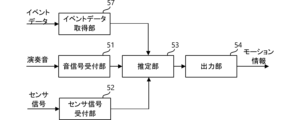
- the CPU 204 configures a sound signal reception section 51, a sensor signal reception section 52, an estimation section 53, an output section 54, and an event data acquisition section 57 using an application program. That is, the CPU 204 of Modification 1 further includes an event data acquisition section 57 functionally.
- the event data acquisition unit 57 acquires event data.
- the event data is, for example, time-series event data based on the MIDI (Musical Instrument Digital Interface) standard, and corresponds to, for example, musical score data for each song.
- the performer specifies the music to be played via the user I/F 202.
- the event data acquisition unit 57 acquires event data by downloading musical score data of a designated song from a server (not shown).
- the estimation unit 53 estimates a performance motion based on a trained model that has been trained on the relationship between performance sounds, sensor signals, event data, and performance motions. Thereby, the estimation unit 53 can particularly improve the estimation accuracy of fingering information.
- Modification 2 The estimation unit 53 of Modification 2 refers to the table and estimates the performance motion.
- the table predefines the relationship between performance sounds, sensor signals, and performance motions.
- the table is registered in advance in the flash memory 203 of the user terminal 12 or in a database in a server (not shown).
- the estimator 53 refers to a table using the performance sound and the sensor signal to identify information on the corresponding performance motion.
- the user terminal 12 can also estimate performance motion without using an artificial intelligence algorithm.
- auxiliary sensor 15 is attached between the nut 74 and the peg 73 of the head 71, it does not interfere with the performance.
- the auxiliary sensor 15 has a magnetic pickup and acquires string vibration as a sensor signal based on changes in the magnetic field.
- the auxiliary sensor 15 is not limited to an example including a magnetic pickup.
- the auxiliary sensor 15 may acquire string vibration as a sensor signal using a camera.
- the auxiliary sensor 15 may acquire images of the left hand and right hand as sensor signals.
- the camera be removably attached to the head 71 of the electric guitar 10 or built in in advance so as not to interfere with the performance.
- the estimation unit 53 estimates the performance motion based on a trained model that has been trained on the relationship between the performance sound, the camera image, and the performance motion.
- the auxiliary sensor 15 may be directly attached to the string located between the nut 74 and the peg 73.
- the auxiliary sensor 15 is, for example, an acceleration sensor.
- the auxiliary sensor 15 detects the acceleration of the string and outputs it as a sensor signal.
- the auxiliary sensor 15 may be a piezoelectric sensor, for example.
- the auxiliary sensor 15 directly contacts the string, detects minute vibrations of the string, and outputs it as a sensor signal.
- These auxiliary sensors 15 come into contact with the string itself and acquire vibrations transmitted inside the string.
- These auxiliary sensors 15 are attached to each of the plurality of strings and detect vibrations of each of the plurality of strings.
- the auxiliary sensors may further include a motion sensor that detects the position or orientation of the instrument.
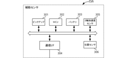
- FIG. 10 is a block diagram showing the configuration of an auxiliary sensor 15A according to modification 5.
- the auxiliary sensor 15A further includes a 3-axis acceleration sensor 305 and a position sensor 306.
- the triaxial acceleration sensor 305 and the position sensor 306 are each examples of motion sensors.
- the triaxial acceleration sensor 305 detects the orientation of the musical instrument.
- Position sensor 306 detects the position of the musical instrument.
- the position sensor 306 may be an indoor positioning sensor such as a BLE (Bluetooth (registered trademark) Low Energy) beacon, or an outdoor positioning sensor such as a GPS (Global Positioning System).
- the estimation unit 53 of the sixth modification detects the position and orientation of the player in addition to the orientation of the musical instrument detected by the triaxial acceleration sensor 305 and the position of the musical instrument detected by the position sensor 306 as in the fifth modification.
- the performer may wear the three-axis acceleration sensor 305 and the position sensor 306 as in Modification 5, and the estimation unit 53 may detect the position and orientation of the performer using these sensors.
- the estimation unit 53 of Modification 6 uses a sensor (for example, a camera installed at a live venue) that is different from the 3-axis acceleration sensor 305 and the position sensor 306 attached to the musical instrument to estimate the position and orientation of the performer. May be detected.
- the estimation unit 53 uses image recognition processing to detect the position of the performer and the position of the musical instrument in the image taken by the camera.
- the estimation unit 53 estimates the positional relationship between the performer and the musical instrument based on the detected position of the performer and the detected position of the musical instrument.
- the output unit 54 outputs motion data indicating the position and orientation of the 3D model of the performer to the 3D model of the instrument placed in the virtual space, based on the positional relationship between the performer and the instrument estimated by the estimation unit 53. generate.
- the performer can control the movement of the instrument and the 3D model of the performer in the virtual space without having to attach motion capture sensors to the body.
- Modification 7 The user terminal 12 of Modification 7 performs acoustic processing on the sound signal based on the sensor signal of the motion sensor described above.
- the user terminal 12 may perform sound image localization processing by convolving a head-related transfer function (HRTF) with a sound signal related to the sound played by the electric guitar 10.
- HRTF head-related transfer function
- Head-related transfer functions are transfer functions from the position of the sound source to the listener's right and left ears.
- the user terminal 12 reads the head-related transfer function corresponding to the position information of the musical instrument from a server or the like and convolves it into the sound signal related to the performance sound. Thereby, the listener can perceive the sound image to be localized at the position of the 3D model in the virtual space.
- the head-related transfer function may differ depending on the orientation of the musical instrument.
- the user terminal 12 reads the head-related transfer function according to the orientation information of the musical instrument from a server or the like, and convolutes it into the sound signal related to the performance sound.
- the listener of the performance sound can localize the sound image to the position of the 3D model in the virtual space, and can also perceive changes in the sound depending on the direction of the musical instrument.
- Modification 8 The user terminal 12 of Modification 8 performs the training stage, which is the generation of a trained model, and the execution stage, which is the estimation of a performance motion.
- the operation in the model training stage and the operation in the trained model execution stage may be performed by one device.
- the server may be the performance motion estimation device of the present invention. That is, the server may perform operations during the model training phase and operations during the trained model execution phase.
- the user terminal 12 transmits information on the sound signal and sensor signal related to the performance sound to the server via the network, and receives information indicating the performance motion from the server.
- the guitar amplifier 11 may be the performance motion estimation device of the present invention.
- the guitar amplifier 11 may perform operations in a model training stage and a trained model execution stage.
- the guitar amplifier 11 receives the sound signal and sensor signal related to the performance sound, and outputs information indicating the performance motion.
- the DSP 106 of the guitar amplifier 11 may perform the acoustic processing shown in the seventh modification. In this case, the DSP 106 functions as an audio processing section.
- the playing motion of the left hand is fingering information
- the playing motion of the right hand is stroke information.
- the playing motions of the left and right hands differ depending on the type of musical instrument. For example, when the musical instrument is a bass, the playing motion of the right hand is information indicating whether it is the index finger or the middle finger of two-finger playing. Alternatively, if the musical instrument is a bass, the playing motion of the right hand becomes information indicating summing or pulling of the slap playing method. If the instrument is a keyboard instrument, both the playing motions of the left hand and the right hand become fingering information.
- the motion data generated in the above embodiment does not need to be distributed in real time.
- the generated motion data may be recorded on the user terminal 12 or a server (not shown).
- a user who performs distribution operates a 3D model that performs virtually in a virtual space using motion data recorded on the user terminal 12 or a server (not shown), etc., and distributes a reproduction of a past performance. It's okay.
- the estimation unit 53 estimated the performance motion based on a trained model that has been trained on the relationship between the performance sound of the electric guitar 10, the sensor signal of the auxiliary sensor 15, and the performance motion.
- the estimation unit 53 may estimate the performance motion based on a trained model that has been trained on the relationship between the sensor signal of the auxiliary sensor 15 and the performance motion. In this case, it is not essential for the estimation unit 53 to input the performance sound of the electric guitar 10.
- the guitar amplifier 11 is not essential in the present invention.
- the DSP of the guitar amplifier 11 to perform signal processing such as effects on the performance sound
- the user terminal 12 does not need to perform such signal processing, and the calculation load on the user terminal 12 can be reduced. .
- Performance motion estimation system 10 Electric guitar 11: Guitar amplifier 12: User terminal 15, 15A: Auxiliary sensor 51: Sound signal reception section 52: Sensor signal reception section 53: Estimation section 54: Output section 57: Event data Acquisition department 71: Head 72: Neck 73: Peg 74: Nut 101: Display 102: User I/F 103: Flash memory 104: CPU 105: RAM 106: DSP 107: Communication I/F 108: Audio I/F 1 09: A/D converter 110: D/A converter 111: Amplifier 112: Speaker 201: Display 202: User I/F 203: Flash memory 204: CPU 205: RAM 206: Communication I/F 301: Pick-up 303: Battery 304: Communication I/F 305: 3-axis acceleration sensor 306: Position sensor
Landscapes
- Physics & Mathematics (AREA)
- Engineering & Computer Science (AREA)
- Acoustics & Sound (AREA)
- Multimedia (AREA)
- Electrophonic Musical Instruments (AREA)
- Auxiliary Devices For Music (AREA)
Abstract
本発明の一実施形態に係る演奏モーション推定方法は、楽器の演奏音に係る音信号を受け付けて、前記楽器に取り付けられた補助センサのセンサ信号を受け付けて、前記音信号および前記センサ信号に基づいて、演奏者の演奏モーションを推定する。
Description
この発明の一実施形態は、演奏者の演奏モーションを推定する方法に関する。
特許文献1には、フレットセンサで指板と指の距離を検出し、フレットを突出させて演奏を補助する弦楽器が開示されている。
特許文献2には、カメラで演奏者を撮影し、撮影結果に基づいて画像認識を用いてハーモニクス奏法を推定する撥弦楽器演奏評価装置が開示されている。
特許文献3には、赤外線センサにより鍵盤楽器の演奏者の手をキャプチャし、ヘッドマウントディスプレイに演奏ガイドを表示する構成が開示されている。
本開示のひとつの態様は、従来よりも演奏者の演奏モーション推定の精度を向上させる演奏モーション推定方法を提供することを目的とする。
本発明の一実施形態に係る演奏モーション推定方法は、楽器の演奏音に係る音信号を受け付けて、前記楽器に取り付けられた補助センサのセンサ信号を受け付けて、前記音信号および前記センサ信号に基づいて、演奏者の演奏モーションを推定する。
本発明の一実施形態によれば、演奏者の演奏モーション推定の精度を向上させることができる。
図1は、演奏モーション推定システム1の一例を示す外観図である。演奏モーション推定システム1は、エレキギター10、ギターアンプ11、ユーザ端末12、および補助センサ15を有する。なお、本発明においてギターアンプ11は必須ではない。エレキギター10は、ギターアンプ11を介さず、ユーザ端末12に接続してもよい。
エレキギター10は、弦楽器の一例である。本実施形態では弦楽器の一例としてエレキギター10を示すが、本発明の弦楽器は、他にも例えばエレキベースや、ヴァイオリン等のアコースティック楽器も含む。また、本発明の楽器は、弦楽器に限らない。本発明の楽器は、例えば、鍵盤楽器あるいは管楽器等の他の種類の楽器も含む。
ギターアンプ11は、オーディオケーブルを介してエレキギター10に接続される。また、ギターアンプ11は、一例としてBluetooth(登録商標)または無線LAN等の無線通信によりユーザ端末12に接続される。無論、ギターアンプ11は、通信ケーブルを介してユーザ端末12に接続してもよい。エレキギター10は、演奏音に係るアナログ音信号をギターアンプ11に出力する。なお、弦楽器がアコースティック楽器の場合、マイクあるいはマグネティックピックアップを用いてギターアンプ11に音信号を入力する。
図2はギターアンプ11の構成を示すブロック図である。ギターアンプ11は、表示器101、ユーザインタフェース(I/F)102、フラッシュメモリ103、CPU104、RAM105、DSP106、通信I/F107、オーディオI/F108、A/D変換器109、D/A変換器110、アンプ111、およびスピーカ112を備えている。
表示器101は、例えばLED、LCD(Liquid Crystal Display)またはOLED(Organic Light-Emitting Diode)等からなり、ギターアンプ11の状態等を表示する。
ユーザI/F102は、摘まみ、スイッチ、またはボタン等からなり、ユーザの操作を受け付ける。また、ユーザI/F102は、表示器101のLCDに積層されるタッチパネルであってもよい。
CPU104は、記憶媒体であるフラッシュメモリ103に記憶されている各種プログラムをRAM105に読み出して、ギターアンプ11を制御する。例えば、CPU104は、ユーザI/F102を介して信号処理に係るパラメータを受け付けて、DSP106およびアンプ111を制御する。
通信I/F107は、Bluetooth(登録商標)または無線LAN等を介して、例えばユーザ端末12等の他装置に接続する。
オーディオI/F108は、アナログオーディオ端子を有する。オーディオI/F108は、オーディオケーブルを介してエレキギター10からアナログ音信号を受け付ける。
A/D変換器109は、オーディオI/F108で受け付けたアナログ音信号をデジタル音信号に変換する。
DSP106は、当該デジタル音信号にエフェクト等の各種の信号処理を施す。信号処理に係るパラメータは、ユーザI/F102を介して受け付ける。DSP106は、信号処理を施した後のデジタル音信号をD/A変換器110に出力する。
CPU104は、DSP106で信号処理を施した後のデジタル音信号、または信号処理を施す前のデジタル音信号を、通信I/F107を介してユーザ端末12に送信する。
D/A変換器110は、DSP106から受け付けたデジタル音信号をアナログ音信号に変換する。アンプ111は、当該アナログ音信号を増幅する。増幅に係るパラメータは、ユーザI/F102を介して受け付ける。
スピーカ112は、アンプ111で増幅されたアナログ音信号に基づいて、エレキギター10の演奏音を出力する。
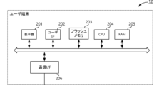
図3はユーザ端末12の構成を示すブロック図である。ユーザ端末12は、パーソナルコンピュータまたはスマートフォン等の情報処理装置である。ユーザ端末12は、表示器201、ユーザI/F202、フラッシュメモリ203、CPU204、RAM205、および通信I/F206を備えている。
表示器201は、例えばLED、LCDまたはOLED等からなり、種々の情報を表示する。ユーザI/F202は、表示器201のLCDまたはOLEDに積層されるタッチパネルである。あるいは、ユーザI/F202は、キーボードまたはマウス等であってもよい。ユーザI/F202がタッチパネルである場合、該ユーザI/F202は、表示器201とともに、GUI(Graphical User Interface)を構成する。
通信I/F206は、Bluetooth(登録商標)または無線LAN等の無線通信によりギターアンプ11および補助センサ15に接続される。ギターアンプ11が通信ケーブルを介してユーザ端末12に接続される場合、通信I/F206は、無線通信で補助センサ15に接続され。ギターアンプ11には通信ケーブルで接続される。
CPU204は、ユーザ端末12の動作を制御する制御部である。CPU204は、記憶媒体であるフラッシュメモリ203に記憶されたアプリケーションプログラム等の所定のプログラムをRAM205に読み出して実行することにより各種の動作を行なう。なお、プログラムは、サーバ(不図示)に記憶されていてもよい。CPU204は、ネットワークを介してサーバからプログラムをダウンロードし、実行してもよい。CPU204は、アプリケーションプログラムを実行することにより演奏モーション推定方法を実行する。
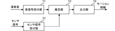
図4は、CPU204の読み出すアプリケーションプログラムの機能ブロック図である。CPU204は、読み出したアプリケーションプログラムにより、音信号受付部51、センサ信号受付部52、推定部53、および出力部54を構成する。
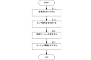
図5は、当該アプリケーションプログラムによる演奏モーション推定方法の動作を示すフローチャートである。音信号受付部51は、通信I/F206を介して、ギターアンプ11からエレキギター10の演奏音に係るデジタル音信号を受け付ける(S11)。また、センサ信号受付部52は、通信I/F206を介して、補助センサ15からセンサ信号を受け付ける(S12)。
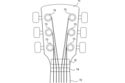
図6は、エレキギター10の一部拡大図である。図7は、補助センサ15の構成を示すブロック図である。
エレキギター10は、ヘッド71およびネック72を有する。ヘッド71には、ペグ73が取り付けられている。ヘッド71およびネック72との境界部分には、ナット74が取り付けられている。
補助センサ15は、ヘッド71のうちナット74からペグ73の間に、例えばヘッド71を表面側および裏面側を挟み込む様な状態で、着脱可能に取り付けられている。そのため、補助センサ15は、演奏の邪魔になることはない。
なお、補助センサ15は、エレキギター10のヘッド71に埋め込まれていてもよいし、粘着剤等でヘッド71に貼り付けてもよい。補助センサ15は、粘着剤等でヘッド71に貼り付ける、あるいはヘッドを挟み込む様に取り付ける場合、本実施形態のエレキギター10に限らず、アコースティックギター等に取り付けることもできる。この様に補助センサ15は、着脱可能に取り付けられることで、センサを内蔵していないギター等の楽器であっても取り付けることができ、どの様な楽器であっても演奏を阻害せずに本実施形態の演奏モーション推定方法を実行することができる。また、補助センサ15は、ヘッド71の裏面側の部分に取り付けてもよい。また、補助センサ15は、ボディの裏面側に取り付けてもよい。これにより、補助センサ15は、演奏の邪魔をせずにヘッド71やボディの裏面側の振動を検出することもできる。
補助センサ15は、図7に示す様に、ピックアップ301、マイクロコントローラユニット(MCU)302、バッテリ303、および通信I/F304を備えている。
ピックアップ301は、ナット74からペグ73の間の弦振動に基づいた音信号を生成する。
MCU302は、メモリおよびプログラムを内蔵し、補助センサ15の動作を制御する。MCU302は、ピックアップ301で生成した音信号をセンサ信号として、通信I/F304を介してユーザ端末12に送信する。
通信I/F206は、Bluetooth(登録商標)または無線LAN等の無線通信により、センサ信号をユーザ端末12に送信する。無論、補助センサ15は、通信ケーブルを介してユーザ端末12に接続してもよい。
ユーザ端末12の推定部53は、補助センサ15から受け付けたセンサ信号およびギターアンプ11から受け付けた音信号に基づいて、演奏者の演奏モーションを推定する(S13)。演奏モーションは、演奏者の右手および左手の演奏モーション情報を含む。
例えば、右利きの演奏者は、左手でネック72のフレットを押さえる。推定部53は、左手の演奏モーションとして、エレキギター10の第1弦から第6弦のそれぞれについて、押さえられているフレットの位置(運指情報)を推定する。
また、右利きの演奏者は、右手で弦を弾く。演奏者は、第1弦側からまたは第6弦側から弦を弾く。推定部53は、右手の演奏モーションとして、第1弦側から弾くアップストロークであるか、第6弦側から弾くダウンストロークであるか、推定する。推定部53は、右手の演奏モーション情報として、ストローク情報を推定する。
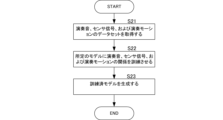
推定部53は、エレキギター10の演奏音と、補助センサ15のセンサ信号と、演奏モーションと、の関係をDNN(Deep Neural Network)で訓練した訓練済モデル(trained model)に基づいて演奏モーションを推定する。訓練は、予め例えば楽器製造者の利用するコンピュータ(サーバ)で実行されるプログラムにより実現する。図8は、訓練段階におけるコンピュータ(サーバ)の動作を示すフローチャートである。
訓練済モデルを生成するコンピュータは、訓練段階として、ある演奏を行った時の左右の手の演奏モーション情報と、エレキギター10の演奏音と、センサ信号と、を含むデータセット(訓練用データ)を多数取得する(S21)。コンピュータは、所定のモデルに、所定のアルゴリズムを用いてエレキギター10の演奏音と、補助センサ15のセンサ信号と、演奏モーション情報と、の関係を訓練させる(S22)。
本実施形態において、モデルを訓練させるためのアルゴリズムは限定されず、CNN(Convolutional Neural Network)やRNN(Recurrent Neural Network)等の任意の機械訓練アルゴリズムを用いることができる。機械訓練アルゴリズムは、教師あり訓練、教師なし訓練、半教師訓練、強化訓練、逆強化訓練、能動訓練、あるいは転移訓練等であってもよい。また、推定部53は、HMM(Hidden Markov Model:隠れマルコフモデル)やSVM(Support Vector Machine)等の機械訓練モデルを用いてモデルを訓練させてもよい。
ある特定の演奏モーションにより演奏を行った時の演奏音(エレキギター10のボディ側の弦振動から取得した音信号)およびセンサ信号(ペグ73およびナット74の間の弦振動から取得した音信号)は一意に決まる。つまり、ある演奏モーションで演奏を行った時の左右の手の演奏モーション情報と、エレキギター10の演奏音と、センサ信号と、は、相関関係を有する。したがって、コンピュータは、所定のモデルに、エレキギター10の演奏音と、補助センサ15のセンサ信号と、演奏モーション情報と、の関係を訓練させ、訓練済モデルを生成する(S23)。
推定部53は、上記の訓練済モデルを、ネットワークを介してコンピュータ(例えば楽器製造者のサーバ)から取得する。推定部53は、実行段階として、当該訓練済モデルにより、受け付けた現在の演奏音信号と、センサ信号と、を入力し、演奏モーション情報を推定する。より具体的には、推定部53は、訓練済モデルにより、左手の運指情報と、右手のストローク情報と、を推定する。
出力部54は、推定部53で推定した演奏モーションに係る情報を出力する(S14)。演奏モーション情報は、例えば仮想空間内で仮想的に演奏を行う3Dモデルを動作させるための時系列のモーションデータに用いられる。
本実施形態のユーザ端末12のユーザは、エレキギター10の演奏者である。エレキギター10の演奏者は、自身の演奏音を配信するとともに仮想空間内で仮想的に演奏を行う自身の分身となる3Dモデルを動作させる。ただし、演奏音の配信を行うユーザと演奏者とは同じ人物である必要はない。ユーザ端末12は、当該3Dモデルの動作を制御するためのモーションデータを生成する。ユーザ端末12は、例えばモーションデータを生成するアプリケーションプログラムをフラッシュメモリ203からRAM205に読み出して実行する。
モーションデータを生成するアプリケーションプログラムは、運指情報に基づいて、楽器の3Dモデルのネックの位置に、演奏者の3Dモデルの左手のボーンを配置するためのモーションデータを生成する。アプリケーションプログラムは、運指情報として例えばCコード(Cの和音)を受け付けた場合、人差し指を第2弦の第1フレットに配置し、中指を第4弦の第2フレットに配置し、薬指を第5弦の第3フレットに配置するモーションデータを生成する。また、アプリケーションプログラムは、ストローク情報に基づいて、演奏者の3Dモデルの右手のボーンをアップストロークまたはダウンストロークで動作させるためのモーションデータを生成する。
以上の様に、推定部53は、音信号だけでなく、補助センサ15のセンサ信号を用いて演奏モーションを推定することで、より高精度に演奏モーションを推定することができる。
また、演奏者は、モーションキャプチャ用のセンサを身体に取り付ける必要なく、仮想空間内の演奏者の3Dモデルの動作を制御することができる。さらに、本実施形態の演奏モーション推定方法の利用者は、仮想空間内における仮想的な演奏をより臨場感を持って提供できるという顧客体験を享受できる。また、仮想的な演奏を試聴するリスナは、仮想空間内の3Dモデルをより臨場感を持って視聴できるという顧客体験を享受できる。
(変形例1)
図9は、変形例1に係るCPU204の機能ブロック図である。CPU204は、アプリケーションプログラムにより、音信号受付部51、センサ信号受付部52、推定部53、出力部54およびイベントデータ取得部57を構成する。すなわち、変形例1のCPU204は、機能的に、さらにイベントデータ取得部57を備えている。
図9は、変形例1に係るCPU204の機能ブロック図である。CPU204は、アプリケーションプログラムにより、音信号受付部51、センサ信号受付部52、推定部53、出力部54およびイベントデータ取得部57を構成する。すなわち、変形例1のCPU204は、機能的に、さらにイベントデータ取得部57を備えている。
イベントデータ取得部57は、イベントデータを取得する。イベントデータは、例えばMIDI(Musical Instrument Digital Interface)規格に準じた時系列のイベントデータであり、例えば曲毎の楽譜データに対応する。演奏者は、ユーザI/F202を介して演奏する曲を指定する。イベントデータ取得部57は、指定された曲の楽譜データをサーバ(不図示)からダウンロードすることで、イベントデータを取得する。
推定部53は、音信号、センサ信号、およびイベントデータに基づいて演奏者の演奏モーションを推定する。イベントデータは、上記の様に楽譜データであり、演奏タイミングおよび音高を示す情報が含まれている。
推定部53は、演奏音、センサ信号、イベントデータ、および演奏モーションの関係を訓練した訓練済モデルに基づいて演奏モーションを推定する。これにより、推定部53は、特に運指情報の推定精度を向上させることができる。
(変形例2)
変形例2の推定部53は、テーブルを参照して、演奏モーションを推定する。テーブルは、予め演奏音、センサ信号、および演奏モーションとの関係を規定している。当該テーブルは、予めユーザ端末12のフラッシュメモリ203または不図示のサーバにおけるデータベースに登録されている。推定部53は、演奏音およびセンサ信号でテーブルを参照して、対応する演奏モーションの情報を特定する。
変形例2の推定部53は、テーブルを参照して、演奏モーションを推定する。テーブルは、予め演奏音、センサ信号、および演奏モーションとの関係を規定している。当該テーブルは、予めユーザ端末12のフラッシュメモリ203または不図示のサーバにおけるデータベースに登録されている。推定部53は、演奏音およびセンサ信号でテーブルを参照して、対応する演奏モーションの情報を特定する。
これにより、ユーザ端末12は、人工知能アルゴリズムを用いることなく演奏モーションを推定することもできる。
(変形例3)
上記実施形態では、補助センサ15は、ヘッド71のうちナット74からペグ73の間に取り付けられていた。しかし、補助センサ15は、例えばネックとボディの境界部分、あるいはブリッジとピックアップの間等に取り付けてもよい。
上記実施形態では、補助センサ15は、ヘッド71のうちナット74からペグ73の間に取り付けられていた。しかし、補助センサ15は、例えばネックとボディの境界部分、あるいはブリッジとピックアップの間等に取り付けてもよい。
ただし、補助センサ15は、ヘッド71のうちナット74からペグ73の間に取り付けられることで、演奏の邪魔になることがない。
(変形例4)
上記実施形態では、補助センサ15は、マグネティックピックアップを有し、磁界変化に基づいて弦振動をセンサ信号として取得した。しかし、補助センサ15は、マグネティックピックアップを備える例に限らない。例えば、補助センサ15は、カメラにより、弦振動をセンサ信号として取得してもよい。あるいは、補助センサ15は、左手および右手の映像をセンサ信号として取得してもよい。この場合も、カメラは、演奏を阻害しないために、エレキギター10のヘッド71に着脱可能に取り付ける、あるいは予め内蔵されていることが好ましい。
上記実施形態では、補助センサ15は、マグネティックピックアップを有し、磁界変化に基づいて弦振動をセンサ信号として取得した。しかし、補助センサ15は、マグネティックピックアップを備える例に限らない。例えば、補助センサ15は、カメラにより、弦振動をセンサ信号として取得してもよい。あるいは、補助センサ15は、左手および右手の映像をセンサ信号として取得してもよい。この場合も、カメラは、演奏を阻害しないために、エレキギター10のヘッド71に着脱可能に取り付ける、あるいは予め内蔵されていることが好ましい。
この場合、推定部53は、演奏音、カメラの映像、および演奏モーションの関係を訓練した訓練済モデルに基づいて演奏モーションを推定する。
また、補助センサ15は、ナット74からペグ73の間に配置されている弦に直接取り付けられてもよい。この場合、補助センサ15は、例えば加速度センサである。補助センサ15は、弦の加速度を検出し、センサ信号として出力する。また、補助センサ15は、例えば圧電センサでもよい。この場合、補助センサ15は、弦に直接接触して弦の微少な振動を検出し、センサ信号として出力する。これらの補助センサ15は、弦自体に接触して弦内部に伝わる振動を取得する。これらの補助センサ15は、複数の弦のそれぞれに取り付けられ、複数の弦のそれぞれの振動を検出する。この場合、補助センサ15は、ナイロン弦等のマグネティックピックアップでは検出できない弦の振動を音信号として出力することができる。また、ヘッド71のうちナット74からペグ73の間に配置されている弦に他の物体が直接接触しても、ボディ側のマグネティックピックアップで取得される演奏音に対する影響はほとんどない。したがって、補助センサ15は、ナット74からペグ73の間に配置されている弦に直接取り付けられることで、演奏音を阻害せず、弦内部に伝わる振動を取得することができ、演奏モーションを推定するためのセンサ信号を適切に検出することができる。
また、補助センサ15は、ダイヤフラム型の振動検出センサであってもよい。この場合、補助センサ15は、ヘッド71またはボディ等に貼り付ける。補助センサ15は、ヘッド71やボディを伝わる弦の振動を検出することができる。
(変形例5)
補助センサは、さらに楽器の位置または向きを検出するモーションセンサを含んでもよい。図10は、変形例5に係る補助センサ15Aの構成を示すブロック図である。
補助センサは、さらに楽器の位置または向きを検出するモーションセンサを含んでもよい。図10は、変形例5に係る補助センサ15Aの構成を示すブロック図である。
補助センサ15Aは、補助センサ15の構成に加えて、さらに3軸加速度センサ305および位置センサ306を備えている。3軸加速度センサ305および位置センサ306は、それぞれモーションセンサの一例である。
3軸加速度センサ305は、楽器の向きを検出する。位置センサ306は、楽器の位置を検出する。位置センサ306は、BLE(Bluetooth(登録商標) Low Energy)ビーコン等の屋内用の測位センサでもよいし、GPS(Global Positioning System)等の屋外用測位センサでもよい。
推定部53は、3軸加速度センサ305で検出した楽器の向き、および位置センサ306で検出した楽器の位置を受け付けて、演奏モーションを推定する。ここで言う演奏モーションは、仮想空間内の楽器および演奏者の3Dモデルの位置および向きを制御するための情報を含む。
出力部54は、左手の運指情報、右手のストローク情報、楽器の位置情報、および楽器の向き情報を演奏モーション情報として出力する。ユーザ端末12のモーションデータを生成するアプリケーションプログラムは、仮想空間内の楽器の3Dモデルの位置および向きを示す時系列のモーションデータを生成する。また、当該アプリケーションプログラムは、仮想空間内に配置した楽器の3Dモデルに合わせて演奏者の3Dモデルの位置および向きを示すモーションデータを生成する。例えば、アプリケーションプログラムは、配置したギターの3Dモデルの背面側に演奏者の3Dモデルを配置し、演奏者の左手のボーンをギターの3Dモデルのネック部分に配置する。また、アプリケーションプログラムは、演奏者の右手のボーンのうち肘に近い部分をギターのボディの上部に配置する。これにより、演奏者は、モーションキャプチャ用のセンサを身体に取り付ける必要なく、仮想空間内の楽器および演奏者3Dモデルの動作を制御することができる。
(変形例6)
変形例6の推定部53は、変形例5の様に3軸加速度センサ305で検出した楽器の向きおよび位置センサ306で検出した楽器の位置に加えて、演奏者の位置および向きを検出する。この場合、変形例5の様に3軸加速度センサ305および位置センサ306を演奏者が身につけて、推定部53がこれらのセンサを用いて演奏者の位置および向きを検出してもよい。一方、変形例6の推定部53は、楽器に取り付けられた3軸加速度センサ305および位置センサ306とは別のセンサ(例えばライブ会場に設置されたカメラ)を用いて演奏者の位置および向きを検出してもよい。例えば、推定部53は、画像認識処理により、カメラで撮影した画像内の演奏者の位置および楽器の位置をそれぞれ検出する。推定部53は、検出した演奏者の位置および楽器の位置に基づいて、演奏者と楽器の位置関係を推定する。出力部54は、推定部53で推定した演奏者と楽器の位置関係に基づいて、仮想空間内に配置した楽器の3Dモデルに対して、演奏者の3Dモデルの位置および向きを示すモーションデータを生成する。この場合も、演奏者は、モーションキャプチャ用のセンサを身体に取り付ける必要なく、仮想空間内の楽器および演奏者の3Dモデルの動作を制御することができる。
変形例6の推定部53は、変形例5の様に3軸加速度センサ305で検出した楽器の向きおよび位置センサ306で検出した楽器の位置に加えて、演奏者の位置および向きを検出する。この場合、変形例5の様に3軸加速度センサ305および位置センサ306を演奏者が身につけて、推定部53がこれらのセンサを用いて演奏者の位置および向きを検出してもよい。一方、変形例6の推定部53は、楽器に取り付けられた3軸加速度センサ305および位置センサ306とは別のセンサ(例えばライブ会場に設置されたカメラ)を用いて演奏者の位置および向きを検出してもよい。例えば、推定部53は、画像認識処理により、カメラで撮影した画像内の演奏者の位置および楽器の位置をそれぞれ検出する。推定部53は、検出した演奏者の位置および楽器の位置に基づいて、演奏者と楽器の位置関係を推定する。出力部54は、推定部53で推定した演奏者と楽器の位置関係に基づいて、仮想空間内に配置した楽器の3Dモデルに対して、演奏者の3Dモデルの位置および向きを示すモーションデータを生成する。この場合も、演奏者は、モーションキャプチャ用のセンサを身体に取り付ける必要なく、仮想空間内の楽器および演奏者の3Dモデルの動作を制御することができる。
(変形例7)
変形例7のユーザ端末12は、上記のモーションセンサのセンサ信号に基づいて音信号に音響処理を施す。
変形例7のユーザ端末12は、上記のモーションセンサのセンサ信号に基づいて音信号に音響処理を施す。
例えば、ユーザ端末12は、エレキギター10の演奏音に係る音信号にパニング処理等の音像定位処理を施す。ユーザ端末12は、演奏音の音信号をLチャンネルおよびRチャンネルに分配し、楽器の位置に基づいてLチャンネルおよびRチャンネルの音量バランスを調整する。例えば、ユーザ端末12は、センサ信号で示される楽器の位置情報が、仮想空間内の右側(リスナから向かって右側)にある場合には、Rチャンネルの音量を大きくし、Lチャンネルの音量を小さくする。これにより、演奏音は、リスナから向かって右側に定位する。したがって、演奏音のリスナは、仮想空間内の3Dモデルの位置に音像が定位する様に知覚することができる。
また、例えば、ユーザ端末12は、エレキギター10の演奏音に係る音信号に頭部伝達関数(HRTF:Head-Related Transfer Function)を畳み込むことで音像定位処理を施してもよい。頭部伝達関数は、音源の位置からリスナの右耳および左耳に至る伝達関数である。ユーザ端末12は、楽器の位置情報に応じた頭部伝達関数をサーバ等から読み出して演奏音に係る音信号に畳み込む。これにより、リスナは、仮想空間内の3Dモデルの位置に音像が定位する様に知覚することができる。
また、頭部伝達関数は、楽器の向きに応じて異なっていてもよい。ユーザ端末12は、楽器の向き情報に応じた頭部伝達関数をサーバ等から読み出して演奏音に係る音信号に畳み込む。これにより、演奏音のリスナは、仮想空間内の3Dモデルの位置に音像が定位し、かつ楽器の向きによる音の変化も知覚することができる。
これにより、リスナは、よりリアルな音像定位を体験することができ、従来では得られなかった顧客体験を得ることができる。
(変形例8)
変形例8のユーザ端末12は、訓練段階である訓練済モデルの生成と、実行段階である演奏モーションの推定と、を行う。つまり、モデルの訓練段階の動作と訓練済モデルの実行段階の動作は、1つの装置で行ってもよい。
変形例8のユーザ端末12は、訓練段階である訓練済モデルの生成と、実行段階である演奏モーションの推定と、を行う。つまり、モデルの訓練段階の動作と訓練済モデルの実行段階の動作は、1つの装置で行ってもよい。
また、サーバが本発明の演奏モーション推定装置であってもよい。つまり、サーバは、モデルの訓練段階の動作と訓練済モデルの実行段階の動作を行ってもよい。この場合、ユーザ端末12は、ネットワークを介して、演奏音に係る音信号およびセンサ信号の情報をサーバに送信し、サーバから演奏モーションを示す情報を受信する。
また、ギターアンプ11が本発明の演奏モーション推定装置であってもよい。ギターアンプ11は、モデルの訓練段階の動作と訓練済モデルの実行段階の動作を行ってもよい。この場合、ギターアンプ11は、演奏音に係る音信号およびセンサ信号を受け付けて、演奏モーションを示す情報を出力する。また、ギターアンプ11のDSP106が変形例7で示した音響処理を行ってもよい。この場合、DSP106が音響処理部として機能する。
(変形例9)
上記実施形態の楽器はエレキギター10であるため、左手の演奏モーションは運指情報であり、右手の演奏モーションは、ストローク情報であった。しかし、左手および右手の演奏モーションは、楽器の種類により異なる。例えば、楽器がベースである場合、右手の演奏モーションは、2フィンガー奏法の人差し指であるか、中指であるかを示す情報になる。あるいは、楽器がベースである場合、右手の演奏モーションは、スラップ奏法のサミングまたはプリングを示す情報になる。楽器が鍵盤楽器である場合、左手および右手の演奏モーションともに運指情報になる。
上記実施形態の楽器はエレキギター10であるため、左手の演奏モーションは運指情報であり、右手の演奏モーションは、ストローク情報であった。しかし、左手および右手の演奏モーションは、楽器の種類により異なる。例えば、楽器がベースである場合、右手の演奏モーションは、2フィンガー奏法の人差し指であるか、中指であるかを示す情報になる。あるいは、楽器がベースである場合、右手の演奏モーションは、スラップ奏法のサミングまたはプリングを示す情報になる。楽器が鍵盤楽器である場合、左手および右手の演奏モーションともに運指情報になる。
(変形例10)
上記実施形態で生成したモーションデータは、リアルタイムに配信する必要はない。例えば、生成したモーションデータは、ユーザ端末12またはサーバ(不図示)等に記録してもよい。配信を行う利用者は、ユーザ端末12またはサーバ(不図示)等に記録したモーションデータを用いて仮想空間内で仮想的に演奏を行う3Dモデルを動作させ、過去の演奏を再現した配信を行ってもよい。
上記実施形態で生成したモーションデータは、リアルタイムに配信する必要はない。例えば、生成したモーションデータは、ユーザ端末12またはサーバ(不図示)等に記録してもよい。配信を行う利用者は、ユーザ端末12またはサーバ(不図示)等に記録したモーションデータを用いて仮想空間内で仮想的に演奏を行う3Dモデルを動作させ、過去の演奏を再現した配信を行ってもよい。
本実施形態の説明は、すべての点で例示であって、制限的なものではないと考えられるべきである。本発明の範囲は、上述の実施形態ではなく、請求の範囲によって示される。さらに、本発明の範囲は、請求の範囲と均等の範囲を含む。
例えば、上記実施形態では、推定部53は、エレキギター10の演奏音と、補助センサ15のセンサ信号と、演奏モーションと、の関係を訓練した訓練済モデルに基づいて演奏モーションを推定した。しかし、例えば、推定部53は、補助センサ15のセンサ信号と、演奏モーションと、の関係を訓練した訓練済モデルに基づいて演奏モーションを推定してもよい。この場合、推定部53は、エレキギター10の演奏音を入力することは必須ではない。
また、上述した様に、本発明においてギターアンプ11は必須ではない。ただし、ギターアンプ11のDSPを用いて演奏音にエフェクト等の信号処理を行うことで、ユーザ端末12がこの様な信号処理を行う必要がなくなり、ユーザ端末12の計算負荷を低減することができる。
また、本実施形態の演奏モーション推定方法は、ユーザ端末12ではなく補助センサ15において行ってもよい。この場合、補助センサ15は、推定した演奏モーション情報をユーザ端末12に送信すればよい。
1 :演奏モーション推定システム10 :エレキギター11 :ギターアンプ12 :ユーザ端末15,15A :補助センサ51 :音信号受付部52 :センサ信号受付部53 :推定部54 :出力部57 :イベントデータ取得部71 :ヘッド72 :ネック73 :ペグ74 :ナット101 :表示器102 :ユーザI/F103 :フラッシュメモリ104 :CPU105 :RAM106 :DSP107 :通信I/F108 :オーディオI/F109 :A/D変換器110 :D/A変換器111 :アンプ112 :スピーカ201 :表示器202 :ユーザI/F203 :フラッシュメモリ204 :CPU205 :RAM206 :通信I/F301 :ピックアップ303 :バッテリ304 :通信I/F305 :3軸加速度センサ306 :位置センサ
Claims (18)
- 楽器の演奏音に係る音信号を受け付けて、
前記楽器に取り付けられた補助センサのセンサ信号を受け付けて、
前記音信号および前記センサ信号に基づいて、演奏者の演奏モーションを推定する、
演奏モーション推定方法。 - 前記楽器はヘッドおよび弦を有する弦楽器であり、
前記補助センサは、前記ヘッドに取り付けられる、
請求項1に記載の演奏モーション推定方法。 - 前記弦楽器はナットおよびペグを有し、
前記補助センサは、前記ナットから前記ペグの間の前記弦に取り付けられる、
請求項2に記載の演奏モーション推定方法。 - 前記補助センサは、前記弦の内部を伝わる振動を検出する、
請求項3に記載の演奏モーション推定方法。 - 前記補助センサは、前記楽器に着脱可能に取り付けられている、
請求項1乃至請求項4のいずれか1項に記載の演奏モーション推定方法。 - 前記演奏モーションは、前記演奏者の右手および左手の演奏モーションを含む、
請求項1乃至請求項4のいずれか1項に記載の演奏モーション推定方法。 - 演奏に関するイベントを示すイベントデータを取得し、
さらに、前記イベントデータに基づいて前記演奏モーションを推定する、
請求項1乃至請求項4のいずれか1項に記載の演奏モーション推定方法。 - 前記補助センサは、前記楽器の位置または向きを検出するモーションセンサを含む、
請求項1乃至請求項4のいずれか1項に記載の演奏モーション推定方法。 - 前記モーションセンサのセンサ信号に基づいて前記音信号の音響処理を行う、
請求項8に記載の演奏モーション推定方法。 - 楽器の演奏音に係る音信号を受け付ける音信号受付部と、
前記楽器に取り付けられた補助センサのセンサ信号を受け付けるセンサ信号受付部と、
前記音信号および前記センサ信号に基づいて、演奏者の演奏モーションを推定する推定部と、
を備えた演奏モーション推定装置。 - 前記楽器はヘッドおよび弦を有する弦楽器であり、
前記補助センサは、前記ヘッドに取り付けられる、
請求項10に記載の演奏モーション推定装置。 - 前記弦楽器はナットおよびペグを有し、
前記補助センサは、前記ナットから前記ペグの間の前記弦に取り付けられる、
請求項11に記載の演奏モーション推定装置。 - 前記補助センサは、前記弦の内部を伝わる振動を検出する、
請求項12に記載の演奏モーション推定装置。 - 前記補助センサは、前記楽器に着脱可能に取り付けられている、
請求項10乃至請求項13のいずれか1項に記載の演奏モーション推定装置。 - 前記演奏モーションは、前記演奏者の右手および左手の演奏モーションを含む、
請求項10乃至請求項13のいずれか1項に記載の演奏モーション推定装置。 - 演奏に関するイベントを示すイベントデータを取得するイベントデータ取得部をさらに備え、
前記推定部は、さらに、前記イベントデータに基づいて前記演奏モーションを推定する、
請求項10乃至請求項13のいずれか1項に記載の演奏モーション推定装置。 - 前記補助センサは、前記楽器の位置または向きを検出するモーションセンサを含む、
請求項10乃至請求項13のいずれか1項に記載の演奏モーション推定装置。 - 前記モーションセンサのセンサ信号に基づいて前記音信号の音響処理を行う音響処理部をさらに備えた、
請求項17に記載の演奏モーション推定装置。
Applications Claiming Priority (2)
| Application Number | Priority Date | Filing Date | Title |
|---|---|---|---|
| JP2022-096219 | 2022-06-15 | ||
| JP2022096219A JP2023182940A (ja) | 2022-06-15 | 2022-06-15 | 演奏モーション推定方法および演奏モーション推定装置 |
Publications (1)
| Publication Number | Publication Date |
|---|---|
| WO2023243293A1 true WO2023243293A1 (ja) | 2023-12-21 |
Family
ID=89191105
Family Applications (1)
| Application Number | Title | Priority Date | Filing Date |
|---|---|---|---|
| PCT/JP2023/018305 Ceased WO2023243293A1 (ja) | 2022-06-15 | 2023-05-16 | 演奏モーション推定方法および演奏モーション推定装置 |
Country Status (2)
| Country | Link |
|---|---|
| JP (1) | JP2023182940A (ja) |
| WO (1) | WO2023243293A1 (ja) |
Citations (6)
| Publication number | Priority date | Publication date | Assignee | Title |
|---|---|---|---|---|
| JPH05127589A (ja) * | 1991-08-12 | 1993-05-25 | Quay-Riang Ho Tracy | 弦楽器の運弓法教授のための方法と装置 |
| JPH0798585A (ja) * | 1993-09-28 | 1995-04-11 | Kenji Tsumura | 電気弦楽器 |
| JP2005279051A (ja) * | 2004-03-30 | 2005-10-13 | Yamaha Corp | 生体情報管理装置および生体情報管理システム |
| JP2010085692A (ja) * | 2008-09-30 | 2010-04-15 | Yamaha Corp | 弦楽器 |
| JP2014523004A (ja) * | 2011-07-12 | 2014-09-08 | オー エム ビー ギターズ リミテッド | 弦楽器と同様の装置を使用する弦楽器、システム及び方法 |
| JP2017181850A (ja) * | 2016-03-31 | 2017-10-05 | 日本テレビ放送網株式会社 | 演奏装置、運指のモーションキャプチャ方法及び演奏支援システム。 |
Family Cites Families (4)
| Publication number | Priority date | Publication date | Assignee | Title |
|---|---|---|---|---|
| JP3767099B2 (ja) * | 1996-07-04 | 2006-04-19 | カシオ計算機株式会社 | 電子弦楽器 |
| US6627808B1 (en) * | 2002-09-03 | 2003-09-30 | Peavey Electronics Corporation | Acoustic modeling apparatus and method |
| JP6756472B2 (ja) * | 2015-10-23 | 2020-09-16 | 医療法人社団皓有会 | 音響処理装置 |
| JP2017173589A (ja) * | 2016-03-24 | 2017-09-28 | ヤマハ株式会社 | 信号処理装置 |
-
2022
- 2022-06-15 JP JP2022096219A patent/JP2023182940A/ja active Pending
-
2023
- 2023-05-16 WO PCT/JP2023/018305 patent/WO2023243293A1/ja not_active Ceased
Patent Citations (6)
| Publication number | Priority date | Publication date | Assignee | Title |
|---|---|---|---|---|
| JPH05127589A (ja) * | 1991-08-12 | 1993-05-25 | Quay-Riang Ho Tracy | 弦楽器の運弓法教授のための方法と装置 |
| JPH0798585A (ja) * | 1993-09-28 | 1995-04-11 | Kenji Tsumura | 電気弦楽器 |
| JP2005279051A (ja) * | 2004-03-30 | 2005-10-13 | Yamaha Corp | 生体情報管理装置および生体情報管理システム |
| JP2010085692A (ja) * | 2008-09-30 | 2010-04-15 | Yamaha Corp | 弦楽器 |
| JP2014523004A (ja) * | 2011-07-12 | 2014-09-08 | オー エム ビー ギターズ リミテッド | 弦楽器と同様の装置を使用する弦楽器、システム及び方法 |
| JP2017181850A (ja) * | 2016-03-31 | 2017-10-05 | 日本テレビ放送網株式会社 | 演奏装置、運指のモーションキャプチャ方法及び演奏支援システム。 |
Also Published As
| Publication number | Publication date |
|---|---|
| JP2023182940A (ja) | 2023-12-27 |
Similar Documents
| Publication | Publication Date | Title |
|---|---|---|
| US10895914B2 (en) | Methods, devices, and methods for creating control signals | |
| US11557269B2 (en) | Information processing method | |
| US20210248986A1 (en) | Stick Controller | |
| US20220180767A1 (en) | Crowd-based device configuration selection of a music teaching system | |
| US20210383714A1 (en) | Information processing device, information processing method, and program | |
| WO2017037342A1 (en) | System for teaching a user to play a musical instrument from musical notation via virtual exercises and a method thereof | |
| JP7528971B2 (ja) | 情報処理方法、情報処理システムおよびプログラム | |
| US20200365123A1 (en) | Information processing method | |
| US11295715B2 (en) | Techniques for controlling the expressive behavior of virtual instruments and related systems and methods | |
| JP7243026B2 (ja) | 演奏解析方法、演奏解析装置およびプログラム | |
| JP2021140065A (ja) | 処理システム、音響システム及びプログラム | |
| US12136351B2 (en) | Information processing apparatus and information processing method | |
| WO2022202264A1 (ja) | 演奏解析方法、演奏解析システムおよびプログラム | |
| JP2023182940A (ja) | 演奏モーション推定方法および演奏モーション推定装置 | |
| WO2023105601A1 (ja) | 情報処理装置、情報処理方法、及びプログラム | |
| JP4665811B2 (ja) | 演奏装置 | |
| Overholt | Advancements in violin-related human-computer interaction | |
| WO2022202267A1 (ja) | 情報処理方法、情報処理システムおよびプログラム | |
| WO2023182005A1 (ja) | データ出力方法、プログラム、データ出力装置および電子楽器 | |
| Nichols | Motion Capture for Musical Expression | |
| Cosentino et al. | Music conductor gesture recognition by using inertial measurement system for human-robot musical interaction | |
| WO2024252918A1 (ja) | 情報処理方法および情報処理装置 | |
| US20250299654A1 (en) | Data processing method and non-transitory computer-readable storage medium | |
| JP7859214B2 (ja) | モデルデータ制御方法、モデルデータ制御装置およびモデルデータ制御プログラム | |
| CN113257210B (zh) | 一种铜制或木制乐器的多模态转谱方法及系统 |
Legal Events
| Date | Code | Title | Description |
|---|---|---|---|
| 121 | Ep: the epo has been informed by wipo that ep was designated in this application |
Ref document number: 23823594 Country of ref document: EP Kind code of ref document: A1 |
|
| NENP | Non-entry into the national phase |
Ref country code: DE |
|
| 122 | Ep: pct application non-entry in european phase |
Ref document number: 23823594 Country of ref document: EP Kind code of ref document: A1 |