WO2023243284A1 - 玩具の可動構造 - Google Patents
玩具の可動構造 Download PDFInfo
- Publication number
- WO2023243284A1 WO2023243284A1 PCT/JP2023/018200 JP2023018200W WO2023243284A1 WO 2023243284 A1 WO2023243284 A1 WO 2023243284A1 JP 2023018200 W JP2023018200 W JP 2023018200W WO 2023243284 A1 WO2023243284 A1 WO 2023243284A1
- Authority
- WO
- WIPO (PCT)
- Prior art keywords
- toy
- movable structure
- outer shell
- skeleton
- shaft
- Prior art date
- Legal status (The legal status is an assumption and is not a legal conclusion. Google has not performed a legal analysis and makes no representation as to the accuracy of the status listed.)
- Ceased
Links
Images






Classifications
-
- A—HUMAN NECESSITIES
- A63—SPORTS; GAMES; AMUSEMENTS
- A63H—TOYS, e.g. TOPS, DOLLS, HOOPS OR BUILDING BLOCKS
- A63H3/00—Dolls
-
- A—HUMAN NECESSITIES
- A63—SPORTS; GAMES; AMUSEMENTS
- A63H—TOYS, e.g. TOPS, DOLLS, HOOPS OR BUILDING BLOCKS
- A63H3/00—Dolls
- A63H3/36—Details; Accessories
Definitions
- the present invention relates to a movable structure for a toy.
- Patent Document 1 an upper arm and a leg are attached to a toy body imitating a robot so as to be movable.
- An object of the present invention is to provide a movable structure for a toy that can increase the interest of the toy.
- the movable structure of the toy is A movable structure for a toy including a first member that is attached to a toy main body constituting a main body portion of the toy so that its direction can be changed,
- the first member is a skeleton connected to the toy body; an outer shell portion surrounding the skeleton portion and forming an outer shell of the first member; Equipped with The outer shell portion is provided to be rotatable about the axis of the skeleton portion with respect to the skeleton portion.
- a movable structure of a toy comprising: A peripheral edge portion on at least one end side of the outer shell portion is configured such that its position in the direction of the axis changes.
- a movable structure of a toy comprising:
- the skeleton portion is configured to be extendable and contractible in length in the direction of the axis.
- a movable structure of a toy comprising:
- the skeleton part has a first shaft (black member in 3D data) having a slide holding hole configured as a long hole along the direction of the axis, and is movable in the direction of the axis within the slide holding hole. It has a second axis.
- a movable structure of a toy comprising: The second shaft is equipped with a pressing member that is biased toward the outer surface in the radial direction of the second shaft, The pressing member is configured to come into contact with the slide holding hole.
- a movable structure of a toy comprising: A contact surface between the pressing member and the slide holding hole is provided with a locking structure by fitting the projections and recesses.
- a movable structure of a toy comprising:
- the outer shell part is configured in a cylindrical shape, and a pair of annular guide walls arranged in the direction of the axis is provided on the inner peripheral surface of the outer shell part,
- the skeleton part has a guide part that protrudes in the radial direction and fits between the pair of guide walls to guide rotation of the outer shell part.
- a movable structure of a toy comprising: An edge guide wall having a surface parallel to the pair of guide walls is provided on the inner circumferential surface of the outer shell at a position aligned with the pair of guide walls and the axis,
- the second shaft is provided with a flange located on the slide holding hole side with respect to the edge guide wall, The position of the flange portion is regulated by the edge guide wall, and the connected state of the first shaft and the second shaft is maintained.
- a movable structure of a toy comprising:
- the skeleton portion has a flat portion on the outer surface of the base portion of the connection portion with the toy main body.
- a movable structure of a toy comprising: The toy body imitates the body of a robot, The first member imitates the thigh of the robot.
- FIG. 1 is a perspective view of a toy according to one embodiment of the present invention.
- FIG. 2 is a front view of the leg portion of the toy shown in FIG. 1 when viewed from the front.
- FIG. 3 is an exploded perspective view of a portion corresponding to the thigh shown in FIG. 2 with the outer shell removed. 2 is a cross-sectional view of a portion taken along line XX shown in FIG. 1.
- FIG. FIG. 3 is an exploded perspective view showing a state in which the skeleton of the portion corresponding to the thigh shown in FIG. 2 is divided into two parts.
- FIG. 3 is an exploded perspective view of the skeleton of a portion corresponding to the thigh shown in FIG. 2, broken down into component parts.
- FIG. 1 is a perspective view of a toy according to one embodiment of the present invention.
- FIG. 2 is a front view of the leg portion of the toy shown in FIG. 1 when viewed from the front.
- FIG. 3 is an exploded
- FIG. 3 is a cross-sectional view of a portion of the thigh shown in FIG. 2 taken along line YY, and shows a state in which the skeleton is short.
- FIG. 3 is a cross-sectional view of a portion of the thigh shown in FIG. 2 along line YY, showing a state in which the skeleton is long.
- FIG. 3 is a side view showing a state in which the thigh is raised forward with the outer shell not rotating and the skeleton being short.
- FIG. 3 is an enlarged front view of the thigh showing a state in which the outer shell is rotated.
- FIG. 3 is a side view showing a state in which the thigh is raised forward after rotating the outer shell. It is a front view showing a state in which the skeleton of one thigh is stretched.
- FIG. 3 is a side view showing a state where the thigh is raised forward with the skeleton of the thigh stretched.
- FIG. 1 is a perspective view of a toy according to one embodiment of the present invention.
- a toy 1 has a structure imitating a humanoid robot, having left and right arm parts 5, left and right leg parts 8, a torso part 2 of the toy main body, and a head part 6.
- the head 6 including the neck portion moves back and forth and left and right.
- the shoulder portion can freely rotate, the upper arm portion 10 and the forearm portion 20 are rotatably and bendably connected by the elbow portion, and the hand portion 30 is also rotatably connected.
- the leg portion 8 is configured such that the thigh portion 40 and the lower leg portion 50 can be bent and rotated by the joint structure of the knee portion.
- the foot portion 60 is also configured to be able to bend and rotate at the ankle.
- the structure of the thigh section 40 which is configured as a first member attached to the body section 2 so that its direction can be changed, will be described.
- the left and right legs 8 are attached to the body 2 on the left and right, and have the same symmetrical configuration, so here, in FIG. The section 40 will be explained.
- FIG. 2 is a front view of the leg portion 8 of the toy 1 shown in FIG. 1, viewed from the front.
- the leg portion 8 has a portion corresponding to the hip joint at the upper end of the thigh portion 40, which is approximately the same as the upper end portion of the skeleton portion 40a (see FIG. 3) extending along the axis CL1.
- a spherical upper connecting portion 42j is connected to the body portion 2.
- the upper connecting portion 42j is rotatably supported via, for example, a shaft pin 81 (see FIG. 6) that passes through the tips of the left and right shaft members 3 extending from the center side of the body portion 2 to the left and right sides in the front and back direction. has been done. Therefore, in FIG.
- the thigh 40 is supported so as to be rotatable about an axis CL2 in the front-rear direction extending in a direction perpendicular to the paper surface. Further, the left and right shaft members 3 supporting the upper connecting portion 42j are attached to the body portion 2 so as to be rotatable about the left and right axis CL3. Therefore, the thigh 40 is supported so as to be rotatable in the front-rear direction about the left and right axis CL3.
- FIG. 3 is an exploded perspective view of the thigh 40 shown in FIG. 2 with the outer shell 43 removed.
- FIG. 4 is a cross-sectional view of a portion taken along line XX shown in FIG.
- the thigh section 40 includes a skeleton section 40a connected to the body section 2 via the left and right shaft members 3, and an outer section that is divided into two parts, for example, in proportion to surround the skeleton section 40a.
- An outer shell portion 43 (43a, 43b) constituting a shell is provided.
- the skeleton portion 40a extends along the axis CL1, and its upper side is connected to the left and right shaft members 3 as described above, and its lower side is connected to the upper end portion 51b of the lower leg portion 50.
- connection part between the lower leg part 50 and the thigh part 40 is such that the upper end part 51b of the lower leg part 50 and the knee side connection part 41b of the skeleton part 40a of the thigh part 40 are penetrated by the knee support shaft 48 and bent. It constitutes a possible knee joint.
- a first axis 41 on the knee joint side (the lower part in the figure) and a second axis 42 on the hip joint side (the upper part in the figure) are connected along the direction of the axis CL1.
- the outer shell portion 43 is rotatably provided with respect to the skeleton portion 40a around the axis CL1 of the skeleton portion 40a.
- the rotatable structure of the outer shell portion 43 is based on a sliding structure between the inner peripheral surface 43is of the outer shell portion 43 and the outer surface of the skeleton portion 40a.
- a pair of annular guide walls 43c arranged in the direction of the axis CL1 are provided on the inner circumferential surface 43is of the outer shell 43, and between the pair of guide walls 43c, a diameter
- the guide portion 41d protruding in the direction is fitted into the guide portion 41d. Therefore, the outer shell portion 43 can rotate in the direction around the axis CL1 with respect to the skeleton portion 40a without being restricted in any way.
- the outer shell portion 43 is configured such that a peripheral edge portion 43e on its upper end side (body portion 2 side) changes position in the direction of the axis CL1. That is, the peripheral portion 43e is configured to have a portion that is close to the body portion 2 and a portion that is remote from the body portion 2.
- FIG. 5 is an exploded perspective view showing a state in which the skeleton of the portion corresponding to the thigh shown in FIG. 2 is divided into two parts.
- the first axis 41 and the second axis 42 of the skeleton part 40a can be separated in the direction of the axis CL1, and in the connected state, the first axis 41 and the second axis 42 have a length along the direction of the axis CL1.
- the first shaft 41 is provided with a slide holding hole 41h that is elongated along the direction of the axis CL1 and has a substantially rectangular cross section
- the second shaft 42 is provided with a slide holding hole 41h.
- a fitting insertion portion 42a having a substantially rectangular cross-sectional shape is provided which can be fitted and inserted into the hole 41h. Therefore, when the first shaft 41 and the second shaft 42 are assembled, the length of the skeleton portion 40a changes as the fitting insertion portion 42a slides within the slide holding hole 41h.
- a disc-shaped flange 42f is provided on the base end side (upper side in the figure) of the fitting insertion portion 42a of the second shaft 42.
- an edge guide is provided on the inner circumferential surface 43is of the outer shell portion 43 with a surface parallel to the pair of guide walls 43c at a position aligned with the guide wall 43c in the direction of the axis CL1 (upper position in the figure).
- a wall 43f is provided.
- the root portion 42b between the upper connecting portion 42j and the collar portion 42f is configured in a semi-cylindrical shape (see FIG. 5) extending in the direction of the axis CL1. That is, the outer circumferential surface of the root portion 42b is configured such that one side thereof is not a circumferential surface but a flat portion 42k that is a flat surface.
- FIG. 6 is an exploded perspective view of the skeleton portion 40a that is finely disassembled into component parts.
- a pressing member 42m that contacts the inner surface of the slide holding hole 41h with a predetermined biasing force is provided on the outer surface in the radial direction of the fitting insertion portion 42a of the second shaft 42 (see FIG. 5). .
- a pressing force applied by an elastic member 42n toward the outer surface in the radial direction of the second shaft 42 is applied to a horizontal hole 42h opened in a direction perpendicular to the sliding direction of the second shaft 42.
- 42 m of members are installed inside. Therefore, when the fitting insertion portion 42a is inserted into the slide holding hole 41h, the pressing member 42m can come into contact with the inner surface of the slide holding hole 41h.
- the first shaft 41 is connected to a holding hole forming portion 41a that forms the slide holding hole 41h and a knee side connecting portion 41b that is connected to the upper end portion 51b on the lower leg portion 50 side and forming a knee joint portion.
- the configuration is as follows.
- the holding hole forming part 41a has a structure that is divided into two parts, and is designed to hold in its mouth a connecting protrusion 41c protruding from the upper end side of the knee side connecting part 41b. Rotatably coupled.
- the two proportionally divided portions are fastened by screws 82 or the like, and the portion where the screws 82 are provided is configured as the above-mentioned protruding guide portion 41d.
- FIG. 7 is a cross-sectional view of a portion taken along line YY in FIG. 2, showing a state in which the skeleton portion 40a is short
- FIG. 8 is a cross-sectional view of a portion taken along line YY of FIG. It is a sectional view showing a state where the skeleton part 40a is long in the figure.
- the fitting insertion portion 42a When the skeleton portion 40a is at its shortest length, as shown in FIG. 7, the fitting insertion portion 42a is inserted deepest into the slide holding hole 41h. In this case, a locking protrusion 42p protruding from the tip end surface of the pressing member 42m fits into the first locking recess 41p. Thereby, the short state of the skeleton portion 40a is maintained. Further, in the short state of the skeleton portion 40a, the peripheral edge portion 43e of the outer shell portion 43 is located close to the upper connecting portion 42j.
- the fitting insertion portion 42a is inserted at the shallowest depth into the slide holding hole 41h.
- the locking protrusion 42p of the pressing member 42m fits into the second locking recess 41q provided on the opening side of the slide holding hole 41h.
- FIG. 9 is a side view showing a state in which the outer shell part 43 is in an initial state (reference state) and the skeleton part 40a is short and the thigh part 40 is raised forward.
- the peripheral edge portion 43e and the lower edge portion 2e of the body portion 2 come into contact with each other at a relatively early stage after the first bending, and the bending angle does not become very large.
- FIG. 10 is an enlarged front view of the thigh 40 showing a state in which the outer shell 43 is rotated from the initial state (reference state).
- FIG. 11 is a side view showing a state in which the thigh 40 is raised forward after the outer shell 43 is rotated.
- the outer shell portion 43 is rotated approximately 90 degrees.
- the peripheral edge portion 43e on the side (inside) that bends the thigh portion 40 becomes distant from the lower end edge portion 2e.
- the peripheral edge portion 43e which is configured to change its position in the direction of the axis CL1, is in a state where the portion retreated toward the knee with respect to the lower edge portion 2e is the inner side of the bend.
- the peripheral portion 43e is bent (rotated about the axis CL3) until it comes into contact with the lower end edge 2e of the body portion 2.
- the bending angle is larger than the bending angle during the bending operation before rotating the outer shell portion 43 (the state shown in FIG. 9).
- the rotation angle of the outer shell portion 43 is described as approximately 90 degrees, it is not limited to this in any way, and the position where the outer shell portion 43 can be bent the most (the position where the thigh portion 40 can be bent the most) is as follows. It depends on the shape of the adjacent lower end edge 2e.
- FIG. 12 is a front view showing the skeleton part 40a in an extended state.
- the distance between the peripheral edge portion 43e and the lower edge portion 2e becomes larger.
- the outer shell portion 43 is rotated 90 degrees to the right as shown in the figure, to further increase the distance between the peripheral edge portion 43e and the lower edge portion 2e on the inside (front side) in the bending direction.
- FIG. 13 is a side view showing a state in which the thigh part 40 is raised forward with the skeleton part 40a extended.
- the bending angle of the thigh 40 becomes very large, as shown in FIG. Bend.
- the flat portion 42k of the root portion 42b of the skeleton portion 40a is largely exposed.
- the bending (rotation) can be performed until the root portion 42b touches the lower end edge 2e.
- the thigh 40 is further moved in the lateral direction (right direction). This further increases the bending angle.
- the outer shell portion 43 is configured to be able to rotate in the outer circumferential direction relative to the skeleton portion 40a, thereby preventing interference with members adjacent to the outer shell portion 43. It becomes possible to change the position, and for example, it becomes possible to widen the permissible range of the connection direction (bending angle, etc.) between the body part 2 and the leg parts 8.
- the skeleton part 40a can expand and contract its length with respect to the length of the outer shell part 43 in the axis CL1 direction, the distance between the outer shell part 43 and the body part 2 can be changed, It becomes possible to avoid interference between the peripheral edge portion 43e of the shell portion and the body portion 2.
- the second shaft 42 can slide while being in contact with the inner surface of the slide holding hole 41h by the pressing member 42m, so that rattling between the second shaft 42 and the slide holding hole 41h can be prevented. It can be eliminated. This allows the first shaft 41 and the second shaft 42 to expand and contract smoothly without wobbling.
- the outer shell part 43 since the pair of circumferential guide walls 43c provided on the inner circumferential surface 43is of the outer shell part 43 are rotatably guided by the protruding guide part 41d of the skeleton part 40a, the outer shell part 43 The portion 43 can be rotated smoothly. Furthermore, since the guide portion 41d is fitted between the pair of guide walls 43c, the axial position of the outer shell portion 43 and the skeleton portion 40a can be regulated (positioned).
- first shaft 41 and the second shaft 42 are connected to each other by engagement between the edge guide wall 43f provided on the outer shell 43 and the flange 42f of the second shaft 42.
- 42 can be regulated to a position where they do not come apart, so a special structure for maintaining the connection between the two shafts 41, 42 is not required between the two shafts 41, 42, and the connection structure can be simplified.
- the outer surface of the base portion 42b of the connecting portion with the body portion 2 of the skeleton portion 40a has a flat portion 42k, so that interference with adjacent members can be suppressed by the flat portion 42k. This allows the range of movement of the connecting parts to be widened.
- the locking protrusion 42p provided on the distal end surface of the pressing member 42m is connected to the first locking protrusion 42p provided on the inner surface of the slide holding hole 41h. Since it is fitted and locked in the recess 41p and the second locking recess 41q, for example, the shortest connected state and the longest connected state of the skeleton part 40a can be maintained.
- the present invention can be modified as appropriate within the scope of its technical concept.
- the movable structure of the thigh 40 has been described, but the movable structure of the toy according to the present invention is not limited to this, and a similar movable structure may be adopted for the upper arm, for example. .
Landscapes
- Toys (AREA)
Abstract
【課題】玩具の興趣性を高めることができる玩具の可動構造を提供する。 【解決手段】玩具の本体部分を構成する玩具本体2対して向きを変更可能に取り付けられる第1部材40を含む玩具の可動構造であって、第1部材40は、玩具本体2に連結された骨格部40aと、骨格部40aを囲み第1部材40の外殻を構成する外殻部43と、を備え、外殻部43は、骨格部40aに対し当該骨格部40aの軸線CL1の回りに回転可能に設けられている、玩具の可動構造。
Description
本発明は、玩具の可動構造に関する。
従来、各種玩具においては、玩具の構成する関節部分の連結構造を備えている。例えば、特許文献1においては、ロボットを模した玩具本体に対して、上腕部や脚部が動くように取り付けられている。
従来のロボットの脚部などの可動構造においては、連結部分を大きく曲げた際に、隣り合う部材間の干渉が生じてしまい、連結部分の曲げ角度が制限される問題が生じる。この結果、例えばロボット玩具のとれる姿勢(ポージング)が制限されてしまうために玩具の興趣性を高めることができない。
本発明は、玩具の興趣性を高めることができる玩具の可動構造を提供することを目的とする。
本発明の一態様の玩具の可動構造は、
玩具の本体部分を構成する玩具本体に対して向きを変更可能に取り付けられる第1部材を含む玩具の可動構造であって、
前記第1部材は、
前記玩具本体に連結された骨格部と、
前記骨格部を囲み前記第1部材の外殻を構成する外殻部と、
を備え、
前記外殻部は、前記骨格部に対し当該骨格部の軸線の回りに回転可能に設けられている、ものである。
玩具の本体部分を構成する玩具本体に対して向きを変更可能に取り付けられる第1部材を含む玩具の可動構造であって、
前記第1部材は、
前記玩具本体に連結された骨格部と、
前記骨格部を囲み前記第1部材の外殻を構成する外殻部と、
を備え、
前記外殻部は、前記骨格部に対し当該骨格部の軸線の回りに回転可能に設けられている、ものである。
本発明の一態様の玩具の可動構造であって、
前記外殻部の少なくとも一端側の周縁部は、前記軸線の方向の位置が変化するように構成されている、ものである。
前記外殻部の少なくとも一端側の周縁部は、前記軸線の方向の位置が変化するように構成されている、ものである。
本発明の一態様の玩具の可動構造であって、
前記骨格部は、前記軸線の方向において、長さが伸縮可能に構成されている、ものである。
前記骨格部は、前記軸線の方向において、長さが伸縮可能に構成されている、ものである。
本発明の一態様の玩具の可動構造であって、
前記骨格部は、前記軸線の方向に沿って長孔に構成されたスライド保持孔を有する第1軸(3Dデータにおける黒の部材)と、前記スライド保持孔内を前記軸線の方向に移動可能な第2軸とを有する、ものである。
前記骨格部は、前記軸線の方向に沿って長孔に構成されたスライド保持孔を有する第1軸(3Dデータにおける黒の部材)と、前記スライド保持孔内を前記軸線の方向に移動可能な第2軸とを有する、ものである。
本発明の一態様の玩具の可動構造であって、
前記第2軸には、当該第2軸の径方向に外面に向って付勢された押圧部材が内装されており、
前記押圧部材が前記スライド保持孔に当接するよう構成されている、ものである。
前記第2軸には、当該第2軸の径方向に外面に向って付勢された押圧部材が内装されており、
前記押圧部材が前記スライド保持孔に当接するよう構成されている、ものである。
本発明の一態様の玩具の可動構造であって、
前記押圧部材と前記スライド保持孔との接触面には、凹凸嵌合による係止構造が設けられている、ものである。
前記押圧部材と前記スライド保持孔との接触面には、凹凸嵌合による係止構造が設けられている、ものである。
本発明の一態様の玩具の可動構造であって、
前記外殻部は筒形に構成され、その内周面には、前記軸線の方向に並んだ環状の一対のガイド壁が設けられ、
前記骨格部は、その径方向に突出して前記一対のガイド壁の間に嵌入し、前記外殻部の回動をガイドするガイド部を有する、ものである。
前記外殻部は筒形に構成され、その内周面には、前記軸線の方向に並んだ環状の一対のガイド壁が設けられ、
前記骨格部は、その径方向に突出して前記一対のガイド壁の間に嵌入し、前記外殻部の回動をガイドするガイド部を有する、ものである。
本発明の一態様の玩具の可動構造であって、
前記外殻部の前記内周面には、前記一対のガイド壁と前記軸線の方向にならんだ位置に前記一対のガイド壁と平行な面を備える縁部ガイド壁が設けられ、
前記第2軸には、前記縁部ガイド壁に対して前記スライド保持孔側に位置する鍔部が設けられ、
前記鍔部が前記縁部ガイド壁にて位置規制されて、前記第1軸と前記第2軸との連結状態が維持される、ものである。
前記外殻部の前記内周面には、前記一対のガイド壁と前記軸線の方向にならんだ位置に前記一対のガイド壁と平行な面を備える縁部ガイド壁が設けられ、
前記第2軸には、前記縁部ガイド壁に対して前記スライド保持孔側に位置する鍔部が設けられ、
前記鍔部が前記縁部ガイド壁にて位置規制されて、前記第1軸と前記第2軸との連結状態が維持される、ものである。
本発明の一態様の玩具の可動構造であって、
前記骨格部は、前記玩具本体との連結部の付根部の外面が偏平部を有している、ものである。
前記骨格部は、前記玩具本体との連結部の付根部の外面が偏平部を有している、ものである。
本発明の一態様の玩具の可動構造であって、
前記玩具本体は、ロボットの胴体部を模し、
前記第1部材は、前記ロボットの大腿部を模している、ものである。
前記玩具本体は、ロボットの胴体部を模し、
前記第1部材は、前記ロボットの大腿部を模している、ものである。
本発明によれば、玩具の興趣性を高めることができる玩具の可動構造を提供することができる。
以下、本発明の一態様について、図面を参照して説明する。なお、以下の説明において、上下、前後、左右の記載については、図1に示す玩具の向きを基準にして記載する。
図1は、本発明の一態様の玩具の斜視図である。
図1において、玩具1は、左右の腕部5、左右の脚部8、玩具本体の胴体部2、及び頭部6を有する、人型のロボットを模した構成である。例えば、頭部6は首部分を含めて前後左右に動く。また、腕部5についても、肩部分が自在に回動し、また、上腕部10と前腕部20とが肘部分によって回動並びに屈曲可能に連結され、更に、手部30も回転可能に連結されている。また、脚部8は、大腿部40、下腿部50が膝部分の関節構造にて屈曲並びに回転可能に構成されている。また、足部60についても足首分において屈曲と回転が可能に構成されている。
図1において、玩具1は、左右の腕部5、左右の脚部8、玩具本体の胴体部2、及び頭部6を有する、人型のロボットを模した構成である。例えば、頭部6は首部分を含めて前後左右に動く。また、腕部5についても、肩部分が自在に回動し、また、上腕部10と前腕部20とが肘部分によって回動並びに屈曲可能に連結され、更に、手部30も回転可能に連結されている。また、脚部8は、大腿部40、下腿部50が膝部分の関節構造にて屈曲並びに回転可能に構成されている。また、足部60についても足首分において屈曲と回転が可能に構成されている。
以下、胴体部2に対して向きを変更可能に取り付けられた第1部材として構成された大腿部40の構造について説明する。なお、左右の脚部8は、胴体部2に左右に取り付けられて、左右対称で同じ構成であるので、ここでは図1において紙面に向って右側(ロボットの左の脚部8)の大腿部40について説明する。
図2は、図1に示す玩具1の脚部8を前面から見た正面図である。
図2に示すように、脚部8は、大腿部40の上端部の股関節に相当する部分には、軸線CL1に沿って延出された骨格部40a(図3参照)の上端部の略球形状の上部連結部42jが胴体部2に連結されている。上部連結部42jは、例えば、胴体部2の中央側から左右側方側に延出された左右軸部材3の先端を前後方向で貫通する軸ピン81(図6参照)を介して回転可能支持されている。したがって、大腿部40は、図2において、紙面に垂直な方向に延びる前後方向のか軸線CL2を中心に回動可能に支持されている。また、上部連結部42jを支えている左右軸部材3は、胴体部2に対して、左右の軸線CL3を中心に回動可能に取付けられている。したがって、大腿部40は、左右の軸線CL3を中心に前後方向に回転可能に支えられている。
図2に示すように、脚部8は、大腿部40の上端部の股関節に相当する部分には、軸線CL1に沿って延出された骨格部40a(図3参照)の上端部の略球形状の上部連結部42jが胴体部2に連結されている。上部連結部42jは、例えば、胴体部2の中央側から左右側方側に延出された左右軸部材3の先端を前後方向で貫通する軸ピン81(図6参照)を介して回転可能支持されている。したがって、大腿部40は、図2において、紙面に垂直な方向に延びる前後方向のか軸線CL2を中心に回動可能に支持されている。また、上部連結部42jを支えている左右軸部材3は、胴体部2に対して、左右の軸線CL3を中心に回動可能に取付けられている。したがって、大腿部40は、左右の軸線CL3を中心に前後方向に回転可能に支えられている。
図3は、図2に示す大腿部40の外殻部43を外した分解斜視図である。図4は、図1に示すX-X線に沿った部分の断面図である。
大腿部40は、図3及び図4に示すように、左右軸部材3を介して胴体部2に連結された骨格部40aと、骨格部40aを囲むように例えば2部材に按分されて外殻を構成する外殻部43(43a,43b)と、を備えている。骨格部40aは、軸線CL1に沿って延出されており、上部側が前掲の如く左右軸部材3に連結され、下部側が下腿部50の上端部51bに連結されている。下腿部50と大腿部40の連結部分は、下腿部50の上端部51bと、大腿部40の骨格部40aの膝側連結部41bと、が膝部支軸48によって貫通され屈曲可能な膝関節を構成している。
骨格部40aは、膝関節部側の第1軸41(図中下側の部分)、及び股関節側の第2軸42(図中上側の部分)が軸線CL1の方向に沿って接続されている。また、外殻部43は、骨格部40aに対し当該骨格部40aの軸線CL1の回りに回転可能に設けられている。この外殻部43の回転可能な構造は、筒形に構成された外殻部43の内周面43isと骨格部40aの外面との摺動構造による。例えば、外殻部43の内周面43isに、軸線CL1の方向に並んだ環状の一対のガイド壁43cが設けられており、この一対のガイド壁43cの間に、骨格部40aの外面に径方向に突出したガイド部41dが嵌り込む構成となっている。したがって、外殻部43は、骨格部40aに対して軸線CL1周りの方向に何ら制限されることなく回転することができる。
また、外殻部43は、その上端側(胴体部2側)における周縁部43eが軸線CL1の方向において位置が変化する構成となっている。すなわち、周縁部43eは、胴体部2に対して接近した部分と離れた部分を有するように構成されている。
図5は、図2に示す大腿部に相当する部分の骨格部を2分した状態を示す分解斜視図である。
図5に示すように、骨格部40aの第1軸41と、第2軸42とは、軸線CL1の方向において分離することができ、連結した状態においては、軸線CL1の方向に沿って長さが伸縮可能に構成されている。この伸縮構造は、例えば、第1軸41には、軸線CL1の方向に沿って長く構成され横断面形状が略矩形のスライド保持孔41hが設けられており、第2軸42には、スライド保持孔41hに嵌合・挿入可能な横断面形状が略矩形状の嵌合挿入部42aが設けられている。したがって、第1軸41と第2軸42とが組み立てられた状態においては、スライド保持孔41h内を嵌合挿入部42aがスライド移動することで骨格部40aの長さが変わる。
図5に示すように、骨格部40aの第1軸41と、第2軸42とは、軸線CL1の方向において分離することができ、連結した状態においては、軸線CL1の方向に沿って長さが伸縮可能に構成されている。この伸縮構造は、例えば、第1軸41には、軸線CL1の方向に沿って長く構成され横断面形状が略矩形のスライド保持孔41hが設けられており、第2軸42には、スライド保持孔41hに嵌合・挿入可能な横断面形状が略矩形状の嵌合挿入部42aが設けられている。したがって、第1軸41と第2軸42とが組み立てられた状態においては、スライド保持孔41h内を嵌合挿入部42aがスライド移動することで骨格部40aの長さが変わる。
また、第2軸42の嵌合挿入部42aの基端側(図中上側)には、円盤状の鍔部42fが設けられている。一方、外殻部43の内周面43isには、一対のガイド壁43cと軸線CL1の方向に並んだ位置(図中において上側の位置)に当該ガイド壁43cと平行な面を備える縁部ガイド壁43fが設けられている。そして、大腿部40が組み立てられた状態(図4に示す状態)においては、鍔部42fは、縁部ガイド壁43fとガイド壁43c(一対のガイド壁43cのうち上側のもの)との間に位置している。これにより、鍔部42fの軸線CL1方向の移動が規制され、且つ第1軸41と第2軸42とが抜けないように連結状態が維持される。
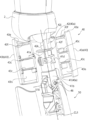
第2軸42においては、上部連結部42jと鍔部42fと間の付根部42bは、軸線CL1方向に延びる半円柱形状(図5参照)に構成されている。すなわち、付根部42bの外周面は、その一方側が円周面ではなく平坦な面の偏平部42kに構成されている。
図6は、骨格部40aを構成要素別に細かく分解した分解斜視図である。
第2軸42の嵌合挿入部42aの径方向の外面(図5参照)には、スライド保持孔41hの内面に対して所定の付勢力を有して接触する押圧部材42mが設けられている。図6に示すように、第2軸42のスライド方向に直交する方向に向って開口した横孔42hに、第2軸42の径方向に外面に向って弾性部材42nにて付勢された押圧部材42mが内装されている。したがって、嵌合挿入部42aがスライド保持孔41hに挿入された状態においては、押圧部材42mは、スライド保持孔41hの内面に当接することができる。
第2軸42の嵌合挿入部42aの径方向の外面(図5参照)には、スライド保持孔41hの内面に対して所定の付勢力を有して接触する押圧部材42mが設けられている。図6に示すように、第2軸42のスライド方向に直交する方向に向って開口した横孔42hに、第2軸42の径方向に外面に向って弾性部材42nにて付勢された押圧部材42mが内装されている。したがって、嵌合挿入部42aがスライド保持孔41hに挿入された状態においては、押圧部材42mは、スライド保持孔41hの内面に当接することができる。
なお、第1軸41は、スライド保持孔41hを構成する保持孔構成部41aと、下腿部50側の上端部51bと連結されて膝関節部分を構成する膝側連結部41bと、が連結された構成となっている。また、保持孔構成部41aは、2つに按分された構造となっており、膝側連結部41bの上端側に突設された連結突起41cを咥え込むようにして、当該連結突起41cに対して回転可能に連結される。また、保持孔構成部41aにおいては、2つに按分部分の締結は、ビス82などによるが、ビス82を設ける部分が前掲の突状のガイド部41dとして構成されている。
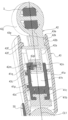
図7は、図2のY-Y線に沿った部分の断面図であって、骨格部40aが短い状態を示す断面図であり、図8は、同じくY-Y線に沿った部分の断面図で骨格部40aが長い状態を示す断面図である。
骨格部40aが最も短くなっている状態においては、図7に示すように、嵌合挿入部42aがスライド保持孔41h内に最も深く挿入されている。この場合、押圧部材42mの先端面に突設された係止突起42pが第1係止凹部41p内に嵌り込んでいる。これにより、骨格部40aの短い状態が維持される。また、この骨格部40aの短い状態においては、外殻部43の周縁部43eは、上部連結部42jに接近した位置となっている。
一方、骨格部40aが最も長くなっている状態においては、図8に示すように、嵌合挿入部42aがスライド保持孔41h内に最も浅く挿入されている。この場合、押圧部材42mの係止突起42pは、スライド保持孔41hの開口側に設けられた第2係止凹部41q内に嵌り込んでいる。これにより、骨格部40aの長い状態が維持される。
図9は、外殻部43を初期状態(基準状態)で且つ骨格部40aが短い状態において大腿部40を前方に上げた状態を示す側面図である。
大腿部40を前方に上げるように曲げ操作するとき、図9に示すように、外殻部43の周縁部43eが上部連結部42jに接近した状態のままで曲げ操作(軸線CL3を中心にした回転)をした場合には、曲げ初めて比較的早い段階で、周縁部43eと胴体部2の下端縁部2eとが接触状態となり、曲げ角度はさほど大きくならない。
大腿部40を前方に上げるように曲げ操作するとき、図9に示すように、外殻部43の周縁部43eが上部連結部42jに接近した状態のままで曲げ操作(軸線CL3を中心にした回転)をした場合には、曲げ初めて比較的早い段階で、周縁部43eと胴体部2の下端縁部2eとが接触状態となり、曲げ角度はさほど大きくならない。
図10は、外殻部43を初期状態(基準状態)から回転させた状態を示す大腿部40の拡大正面図である。図11は、外殻部43を回転させた後に大腿部40を前方に上げた状態を示す側面図である。
脚部8の曲げ操作を行う前に、図10に示すように、例えば、外殻部43を略90度程度回転する操作を行う。このように外殻部43を回転させると、大腿部40を曲げる側(内側)の周縁部43eが下端縁部2eに対して距離が離れるようになる。すなわち、軸線CL1方向の位置が変化するように構成された周縁部43eは、下端縁部2eに対して膝側に後退した部位を、曲げる内側とした状態とされている。この状態で、図11に示すように、周縁部43eが胴体部2の下端縁部2eに接触するまで曲げる(軸線CL3を中心にした回転)。この場合においては、外殻部43を回転させる前の曲げ動作のときの曲がり角度(図9に示す状態)に比べて曲げ角度が大きくなる。
なお、外殻部43の回転角度について、略90度程度と記載したが、これに何ら制限されるものではなく、最も大きく曲がる位置(大腿部40を最も大きく曲げることができる位置)は、隣接する下端縁部2eの形状によって左右される。
脚部8の曲げ操作を行う前に、図10に示すように、例えば、外殻部43を略90度程度回転する操作を行う。このように外殻部43を回転させると、大腿部40を曲げる側(内側)の周縁部43eが下端縁部2eに対して距離が離れるようになる。すなわち、軸線CL1方向の位置が変化するように構成された周縁部43eは、下端縁部2eに対して膝側に後退した部位を、曲げる内側とした状態とされている。この状態で、図11に示すように、周縁部43eが胴体部2の下端縁部2eに接触するまで曲げる(軸線CL3を中心にした回転)。この場合においては、外殻部43を回転させる前の曲げ動作のときの曲がり角度(図9に示す状態)に比べて曲げ角度が大きくなる。
なお、外殻部43の回転角度について、略90度程度と記載したが、これに何ら制限されるものではなく、最も大きく曲がる位置(大腿部40を最も大きく曲げることができる位置)は、隣接する下端縁部2eの形状によって左右される。
図12は、骨格部40aを伸ばした状態を示す正面図である。
図10に示すように、骨格部40aを長くした場合には、周縁部43eと下端縁部2eとの距離は大きくなる。また、外殻部43を図示の如く右方向へ90度回転させて、曲げ方向内側(前方側)における周縁部43eと下端縁部2eの距離を更に大きくする。
図10に示すように、骨格部40aを長くした場合には、周縁部43eと下端縁部2eとの距離は大きくなる。また、外殻部43を図示の如く右方向へ90度回転させて、曲げ方向内側(前方側)における周縁部43eと下端縁部2eの距離を更に大きくする。
図13は、骨格部40aを伸ばした状態において大腿部40を前方に上げた状態を示す側面図である。
前掲のように骨格部40aを引き延ばす操作と共に外殻部43を回転する操作を行った状態で曲げ操作をした場合には、図11に示すように、大腿部40の曲げ角度は非常に大きく曲がる。また、この場合、骨格部40aの付根部42bの偏平部42kが大きく露出する。これにより、付根部42bが下端縁部2eに接するところまで曲げ(回転)を行うことができる。また、図11に示したように、大腿部40を前方に大きく曲げた状態において、更に、上部連結部42jの軸線CL2を中心にして、大腿部40を胴体部2の横方向(右方向)に広げるように回転することができる。これにより、曲がり角度はさらに大きくなる。
前掲のように骨格部40aを引き延ばす操作と共に外殻部43を回転する操作を行った状態で曲げ操作をした場合には、図11に示すように、大腿部40の曲げ角度は非常に大きく曲がる。また、この場合、骨格部40aの付根部42bの偏平部42kが大きく露出する。これにより、付根部42bが下端縁部2eに接するところまで曲げ(回転)を行うことができる。また、図11に示したように、大腿部40を前方に大きく曲げた状態において、更に、上部連結部42jの軸線CL2を中心にして、大腿部40を胴体部2の横方向(右方向)に広げるように回転することができる。これにより、曲がり角度はさらに大きくなる。
以上述べたように、本発明の一態様においては、外殻部43が骨格部40aに対してその外周方向に回転できるように構成されたことで、外殻部43に隣接する部材との干渉位置を変えることが可能となり、例えば、胴体部2と脚部8の連結向き(曲げ角度等)の許容範囲を広げることが可能になる。
本態様においては、外殻部43の周縁部43eが軸線CL1方向に変化するように構成されていることで、外殻部43に隣接する部材との干渉する位置を変えることができる。
本態様においては、骨格部40aが外殻部43の軸線CL1方向の長さに対して、その長さが伸縮できることで、外殻部43と胴体部2との距離を変えることができ、外殻部の周縁部43eと胴体部2との干渉を回避することが可能となる。
本態様の骨格部40aにおいて、第2軸42が第1軸41のスライド保持孔41hによりガイドされた状態でスライド移動できることから、骨格部40aの長さを変更することができる。
本態様においては、第2軸42は、押圧部材42mによってスライド保持孔41hの内面に当接した状態でスライド移動することができるので、第2軸42とスライド保持孔41hとのがた付きを無くすことができる。これにより、第1軸41と第2軸42とがガタ付くことなくスムースに伸縮することができる。
本態様においては、外殻部43の内周面43isに設けられた円周状の一対のガイド壁43cが骨格部40aの突状のガイド部41dにて回転可能にガイドされるので、外殻部43の回転を円滑に行うことができる。また、一対のガイド壁43c間にガイド部41dが嵌入した構成であるので、外殻部43と骨格部40aとの軸方向の位置を規制(位置決め)することができる。
本態様においては、第1軸41と第2軸42との連結状態は、外殻部43に設けられた縁部ガイド壁43fと第2軸42の鍔部42fとの係合により両軸41,42間が外れない位置に位置規制できるので、両軸41,42同士の連結を維持するための特別な構造を当該両軸41,42間において必要とせず、連結構造を簡素化できる。
本態様においては、骨格部40aは、胴体部2との連結部分の付根部42bの外面が偏平部42kを有していることで、この偏平部42kによって隣接する部材との干渉を抑えつことができ、連結部分の可動範囲を広くできる。
本態様においては、スライド保持孔41hと嵌合挿入部42aとの嵌合において、押圧部材42mの先端面に設けられた係止突起42pがスライド保持孔41hの内面に設けられた第1係止凹部41p、及びに第2係止凹部41qに嵌合係止されるので、例えば、骨格部40aの最短連結状態、最長連結状を維持することができる。
以上、本発明の一態様について説明したが、本発明はその技術思想の範囲で適宜変更することができる。例えば、本態様においては、大腿部40の可動構造について説明したが、本発明に係る玩具の可動構造はこれに限るものではなく、例えば上腕部においても同様な可動構造を採用しても良い。
1 玩具
2 胴体部(玩具本体)
40 大腿部(第1部材)
40a 骨格部
41 第1軸
41d ガイド部
41h スライド保持孔
42 第2軸
42b 付根部
42f 鍔部
42j 上部連結部(連結部)
42k 偏平部
42m 押圧部材
43 外殻部
43c 一対のガイド壁
43e 周縁部
43f 縁部ガイド壁
43is 内周面
CL1 骨格部の軸線
2 胴体部(玩具本体)
40 大腿部(第1部材)
40a 骨格部
41 第1軸
41d ガイド部
41h スライド保持孔
42 第2軸
42b 付根部
42f 鍔部
42j 上部連結部(連結部)
42k 偏平部
42m 押圧部材
43 外殻部
43c 一対のガイド壁
43e 周縁部
43f 縁部ガイド壁
43is 内周面
CL1 骨格部の軸線
Claims (10)
- 玩具の本体部分を構成する玩具本体に対して向きを変更可能に取り付けられる第1部材を含む玩具の可動構造であって、
前記第1部材は、
前記玩具本体に連結された骨格部と、
前記骨格部を囲み前記第1部材の外殻を構成する外殻部と、
を備え、
前記外殻部は、前記骨格部に対し当該骨格部の軸線の回りに回転可能に設けられている、
玩具の可動構造。 - 請求項1に記載の玩具の可動構造であって、
前記外殻部の少なくとも一端側の周縁部は、前記軸線の方向の位置が変化するように構成されている、
玩具の可動構造。 - 請求項1または2に記載の玩具の可動構造であって、
前記骨格部は、前記軸線の方向において、長さが伸縮可能に構成されている、
玩具の可動構造。 - 請求項1ないし3のいずれか一項に記載の玩具の可動構造であって、
前記骨格部は、前記軸線の方向に沿って長孔に構成されたスライド保持孔を有する第1軸と、前記スライド保持孔内を前記軸線の方向に移動可能な第2軸とを有する、
玩具の可動構造。 - 請求項4に記載の玩具の可動構造であって、
前記第2軸には、当該第2軸の径方向に外面に向って付勢された押圧部材が内装されており、
前記押圧部材が前記スライド保持孔に当接するよう構成されている、
玩具の可動構造。 - 請求項4または5に記載の玩具の可動構造であって、
前記押圧部材と前記スライド保持孔との接触面には、凹凸嵌合による係止構造が設けられている、
玩具の可動構造。 - 請求項1から6の何れか一項に記載の玩具の可動構造であって、
前記外殻部は筒形に構成され、その内周面には、前記軸線の方向に並んだ環状の一対のガイド壁が設けられ、
前記骨格部は、その径方向に突出して前記一対のガイド壁の間に嵌入し、前記外殻部の回動をガイドするガイド部を有する、
玩具の可動構造。 - 請求項7に記載の玩具の可動構造であって、
前記外殻部の前記内周面には、前記一対のガイド壁と前記軸線の方向にならんだ位置に前記一対のガイド壁と平行な面を備える縁部ガイド壁が設けられ、
前記第2軸には、前記縁部ガイド壁に対して前記スライド保持孔側に位置する鍔部が設けられ、
前記鍔部が前記縁部ガイド壁にて位置規制されて、前記第1軸と前記第2軸との連結状態が維持される、
玩具の可動構造。 - 請求項1から8の何れか一項に記載の玩具の可動構造であって、
前記骨格部は、前記玩具本体との連結部の付根部の外面が偏平部を有している、
玩具の可動構造。 - 請求項1から9の何れか一項に記載の玩具の可動構造であって、
前記玩具本体は、ロボットの胴体部を模し、
前記第1部材は、前記ロボットの大腿部を模している、
玩具の可動構造。
Applications Claiming Priority (2)
| Application Number | Priority Date | Filing Date | Title |
|---|---|---|---|
| JP2022-096686 | 2022-06-15 | ||
| JP2022096686A JP7342201B1 (ja) | 2022-06-15 | 2022-06-15 | 玩具 |
Publications (1)
| Publication Number | Publication Date |
|---|---|
| WO2023243284A1 true WO2023243284A1 (ja) | 2023-12-21 |
Family
ID=87637497
Family Applications (1)
| Application Number | Title | Priority Date | Filing Date |
|---|---|---|---|
| PCT/JP2023/018200 Ceased WO2023243284A1 (ja) | 2022-06-15 | 2023-05-16 | 玩具の可動構造 |
Country Status (3)
| Country | Link |
|---|---|
| JP (2) | JP7342201B1 (ja) |
| CN (1) | CN116617676A (ja) |
| WO (1) | WO2023243284A1 (ja) |
Families Citing this family (5)
| Publication number | Priority date | Publication date | Assignee | Title |
|---|---|---|---|---|
| JP7342200B1 (ja) * | 2022-06-15 | 2023-09-11 | 株式会社バンダイ | 玩具の射出機構 |
| JP7614285B1 (ja) | 2023-10-04 | 2025-01-15 | 株式会社バンダイ | 模型玩具、及び可動構造体 |
| JP7460842B1 (ja) * | 2023-10-04 | 2024-04-02 | 株式会社バンダイ | 模型玩具、及び可動構造体 |
| JP7535205B1 (ja) * | 2024-03-19 | 2024-08-15 | 株式会社バンダイ | 模型玩具用部品、および模型玩具 |
| JP7752272B1 (ja) * | 2025-03-21 | 2025-10-09 | 株式会社バンダイ | 模型玩具、及び模型部品 |
Citations (6)
| Publication number | Priority date | Publication date | Assignee | Title |
|---|---|---|---|---|
| JP2006158542A (ja) * | 2004-12-03 | 2006-06-22 | Volks Inc | 人形の脚部構造及び該脚部構造を備える人形 |
| JP3136840U (ja) * | 2007-08-08 | 2007-11-08 | 株式会社海洋堂 | 可動玩具 |
| WO2009116526A1 (ja) * | 2008-03-18 | 2009-09-24 | 株式会社コナミデジタルエンタテインメント | 変形玩具 |
| JP2012105859A (ja) * | 2010-11-18 | 2012-06-07 | Volks Inc | 人形玩具及び該人形玩具の骨格体 |
| JP2012210459A (ja) * | 2012-07-04 | 2012-11-01 | Konami Digital Entertainment Co Ltd | 人形玩具 |
| JP2013135759A (ja) * | 2011-12-28 | 2013-07-11 | Volks Inc | 腕部構造及び該腕部構造を備えた人形 |
-
2022
- 2022-06-15 JP JP2022096686A patent/JP7342201B1/ja active Active
-
2023
- 2023-05-12 CN CN202310531886.1A patent/CN116617676A/zh active Pending
- 2023-05-16 WO PCT/JP2023/018200 patent/WO2023243284A1/ja not_active Ceased
- 2023-08-30 JP JP2023140207A patent/JP2023183412A/ja active Pending
Patent Citations (6)
| Publication number | Priority date | Publication date | Assignee | Title |
|---|---|---|---|---|
| JP2006158542A (ja) * | 2004-12-03 | 2006-06-22 | Volks Inc | 人形の脚部構造及び該脚部構造を備える人形 |
| JP3136840U (ja) * | 2007-08-08 | 2007-11-08 | 株式会社海洋堂 | 可動玩具 |
| WO2009116526A1 (ja) * | 2008-03-18 | 2009-09-24 | 株式会社コナミデジタルエンタテインメント | 変形玩具 |
| JP2012105859A (ja) * | 2010-11-18 | 2012-06-07 | Volks Inc | 人形玩具及び該人形玩具の骨格体 |
| JP2013135759A (ja) * | 2011-12-28 | 2013-07-11 | Volks Inc | 腕部構造及び該腕部構造を備えた人形 |
| JP2012210459A (ja) * | 2012-07-04 | 2012-11-01 | Konami Digital Entertainment Co Ltd | 人形玩具 |
Non-Patent Citations (2)
| Title |
|---|
| LIVEDOOR.: "Super Robot Chogokin Mazinger ZERO Review ", 26 May 2017 (2017-05-26), pages 1 - 21, XP009551078 * |
| PADO-SAN: "Bandai: Soul of Chogokin GX-45 Mazinger Z", KURUTEN CO., LTD, 1 June 2009 (2009-06-01), pages 1 - 8, XP093117062, Retrieved from the Internet <URL:https://blog.kuruten.jp/bat/76926> [retrieved on 20240109] * |
Also Published As
| Publication number | Publication date |
|---|---|
| JP2023183412A (ja) | 2023-12-27 |
| JP2023183191A (ja) | 2023-12-27 |
| CN116617676A (zh) | 2023-08-22 |
| JP7342201B1 (ja) | 2023-09-11 |
Similar Documents
| Publication | Publication Date | Title |
|---|---|---|
| JP7342201B1 (ja) | 玩具 | |
| CN102397701B (zh) | 人形玩具体的关节构造 | |
| JP6745717B2 (ja) | 人形玩具の手首関節構造及び人形玩具 | |
| JP4235230B2 (ja) | 形態変形玩具用脚部材 | |
| JP6144119B2 (ja) | 人形の関節構造 | |
| CN113101677B (zh) | 玩具部件和人形玩具 | |
| US3942284A (en) | Doll with seven spherical torso joints and five appendages held by three-secured elastic members | |
| JP4853663B2 (ja) | 人形の関節構造及び該関節構造を備えた人形 | |
| WO2022050112A1 (ja) | パーツ連結構造及び人形玩具 | |
| CN104185494B (zh) | 人偶玩具的关节构造 | |
| JP7342200B1 (ja) | 玩具の射出機構 | |
| JP6957696B2 (ja) | 人形玩具の手首関節構造及び人形玩具 | |
| JP5954614B2 (ja) | 腕部構造及び該腕部構造を備えた人形 | |
| JP4853664B2 (ja) | 人形の関節構造及び該関節構造を備えた人形 | |
| JP7738206B1 (ja) | 模型部品、および模型玩具 | |
| JP6061212B1 (ja) | 可動関節構造及び該可動関節構造を備えたフィギュア | |
| JP6290485B2 (ja) | 人形玩具の関節構造 | |
| JP6116205B2 (ja) | 人形玩具の関節構造 | |
| KR200258122Y1 (ko) | 가동형 모형팔 | |
| CN117018637A (zh) | 玩具穿套结构及玩具 | |
| JP2022000266A (ja) | 人形玩具の手首関節構造及び人形玩具 | |
| JP5753107B2 (ja) | 人形体の関節構造 | |
| KR20060039236A (ko) | 완구의 관절장치 | |
| HK1233209A1 (en) | Doll toy shoulder-joint structure and doll toy | |
| JPH0743064U (ja) | 掃除機用伸縮自在吸入パイプ |
Legal Events
| Date | Code | Title | Description |
|---|---|---|---|
| 121 | Ep: the epo has been informed by wipo that ep was designated in this application |
Ref document number: 23823585 Country of ref document: EP Kind code of ref document: A1 |
|
| NENP | Non-entry into the national phase |
Ref country code: DE |
|
| 122 | Ep: pct application non-entry in european phase |
Ref document number: 23823585 Country of ref document: EP Kind code of ref document: A1 |