WO2023243283A1 - 玩具の射出機構 - Google Patents
玩具の射出機構 Download PDFInfo
- Publication number
- WO2023243283A1 WO2023243283A1 PCT/JP2023/018199 JP2023018199W WO2023243283A1 WO 2023243283 A1 WO2023243283 A1 WO 2023243283A1 JP 2023018199 W JP2023018199 W JP 2023018199W WO 2023243283 A1 WO2023243283 A1 WO 2023243283A1
- Authority
- WO
- WIPO (PCT)
- Prior art keywords
- toy
- injection
- injection mechanism
- launch pad
- outer shell
- Prior art date
- Legal status (The legal status is an assumption and is not a legal conclusion. Google has not performed a legal analysis and makes no representation as to the accuracy of the status listed.)
- Ceased
Links
Images




Classifications
-
- A—HUMAN NECESSITIES
- A63—SPORTS; GAMES; AMUSEMENTS
- A63H—TOYS, e.g. TOPS, DOLLS, HOOPS OR BUILDING BLOCKS
- A63H3/00—Dolls
-
- A—HUMAN NECESSITIES
- A63—SPORTS; GAMES; AMUSEMENTS
- A63H—TOYS, e.g. TOPS, DOLLS, HOOPS OR BUILDING BLOCKS
- A63H3/00—Dolls
- A63H3/36—Details; Accessories
Definitions
- the present invention relates to an injection mechanism for a toy.
- Patent Document 1 an upper arm is attached to a toy body imitating a robot, and a forearm is detachable from the distal end of the upper arm, and the forearm is launched by a coil spring.
- Patent Document 1 has an interesting configuration as a toy in which the forearm part of the robot is ejected.
- other functions such as the ability to not only fire but also have joints and bend, and in addition to the firing function of toys, highly interesting toys that also have the joint function of robots etc. is required.
- An object of the present invention is to provide an ejection mechanism for a toy that is highly entertaining.
- the injection mechanism of the toy includes: a launch pad section attached to the toy body; an injection member attached to the launch pad section so as to be able to be ejected from the launch pad section;
- the launch pad section includes a pressing member that presses the injection member in the injection direction,
- the injection member includes a pressed part that receives the force of the pressing member, and an angle variable part that can change the attachment angle with the launch pad part when attached to the launch pad part. It is.
- An injection mechanism for a toy comprising: The launching pad portion is configured such that a portion attached to the toy main body is rotatable.
- An injection mechanism for a toy comprising:
- the launch pad portion includes a cylindrical outer shell portion
- the pressing member includes an elastic member that expands and contracts along the inner surface of the outer shell portion, and a pressing piece that engages with one end of the elastic member and is movable along the inner surface so as to be able to press the pressed portion. It is something that is equipped with.
- An injection mechanism for a toy comprising:
- the injection member includes a cylindrical injection shell, and the pressed portion projects from one end side of the injection shell.
- An injection mechanism for a toy comprising: The pressed portion is provided with the angle variable portion at an end opposite to the launch pad portion.
- An injection mechanism for a toy comprising: The pressed portion has a protruding tip end side protruding from the injection shell portion having an uneven surface.
- An injection mechanism for a toy comprising:
- the launch pad section is provided with a switch member that locks the injection member and enables release of the lock
- the switch member has a shape extending in the injection direction of the injection member from the mounting base side of the launch pad, and includes a locking piece portion for locking the injection member at one end in the longitudinal direction, and a locking piece portion that locks the injection member at the other end. It is equipped with a moving shaft and an operating piece.
- An injection mechanism for a toy comprising:
- the switch member constitutes an outer shell of the launch pad section.
- An injection mechanism for a toy comprising:
- the launch pad portion includes a cylindrical outer shell portion,
- the pressing member includes an elastic member that expands and contracts along the inner surface of the outer shell,
- the switch member is biased by the elastic member in a direction in which the locking piece portion locks the injection member.
- An injection mechanism for a toy comprising: The toy body imitates the body of a robot, The launch pad part imitates the upper arm part of the robot, The injection member imitates a forearm and a hand of the robot, and the angle variable part imitates an elbow.
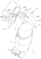
- FIG. 1 is a perspective view of a toy according to one embodiment of the present invention.
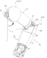
- FIG. 2 is an enlarged perspective view of an arm portion of the toy shown in FIG. 1.
- FIG. 3 is a perspective view showing the arm shown in FIG. 2 in a bent state.
- 3 is an exploded perspective view of the arm shown in FIG. 2.
- FIG. FIG. 2 is a sectional view of the arm portion of the toy shown in FIG. 1 in a separated state taken along line XX when viewed from the front. It is a sectional view showing a state of connection between the upper arm and the injection member.
- FIG. 1 is a perspective view of a toy according to one embodiment of the present invention.
- FIG. 2 is an enlarged perspective view of an arm portion of the toy shown in FIG. 1.
- FIG. 3 is a perspective view showing the arm shown in FIG. 2 in a bent state.
- 3 is an exploded perspective view of the arm shown in FIG. 2.
- FIG. FIG. 2 is a sectional
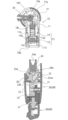
- FIG. 2 is a cross-sectional view of the arm for explaining the injection operation of the injection member, and is a cross-sectional view taken along line YY when the arm of the toy shown in FIG. 1 is viewed from the side. It is a perspective view of an arm part for explaining injection operation of an injection member.
- FIG. 7 is a sectional view of a main part showing a modified example of the pressed part.
- FIG. 1 is a perspective view of a toy according to one embodiment of the present invention.
- a toy 1 has a configuration imitating a humanoid robot, having left and right arms 5, left and right legs 8, a torso 2 of the toy body, and a head 3.
- the head 3 including the neck portion moves back and forth and left and right.
- the shoulder portion can freely rotate, the upper arm portion 10 and the forearm portion 20 are rotatably and bendably connected by the elbow portion, and the hand portion 30 is also rotatably connected.
- the leg portion 8 is configured such that the thigh portion 40 and the lower leg portion 50 can be bent and rotated by the joint structure of the knee portion.
- the foot portion 60 is also configured to be able to bend and rotate at the ankle.
- the left and right arm sections 5 are attached to the body section 2 on the left and right sides, and are symmetrical and have the same configuration. Therefore, the arm 5 on the right side (left arm of the robot) in FIG. 1 will be explained here.
- FIG. 2 is an enlarged perspective view of the arm portion 5 of the toy 1 shown in FIG.
- the arm section 5 includes an upper arm section 10, a forearm section 20, and a hand section 30.
- the upper arm portion 10 is connected to the body portion 2 at the shoulder portion.
- the configuration of the mounting portion 4 of the shoulder portion is made up of a plurality of members rotating in different directions.
- the attachment part 4 includes a first support shaft 16a provided at the upper end of the upper arm part 10 in the front-rear direction of the body part 2, and one end of which is rotatably attached to the first support shaft 16a and the other end of which is attached to the body part 2.
- a disc-shaped second mounting part 2b that rotatably supports the other end of the first mounting part 2a, and a second mounting part 2b that is fixed to the body part 2 and rotates to the right.
- a third mounting portion 2c that protrudes and engages with one end side (front side) portion of the second mounting portion 2b so as to overlap in the vertical direction, and an overlap between the third mounting portion 2c and the one end side of the second mounting portion. It has a second support shaft 16b that penetrates and supports the portion in the vertical direction.
- first support shaft 16a passes through the upper arm portion 10 substantially along the front-rear direction of the body portion 2, and also passes through one end portion of the first attachment portion 2a. Therefore, the upper arm portion 10 is rotatable in the direction just lateral to the body portion 2 about the first rotation axis CL1 extending in the front-rear direction. Moreover, the first attachment part 2a is rotatably provided in the second attachment part 2b around a second rotation axis CL2 extending in the left-right direction. Therefore, the upper arm portion 10 can rotate in the front-back rotation plane. Further, the second attachment portion 2b is rotatable in the horizontal rotation plane about the third rotation axis CL3 in the vertical direction via the second support shaft 16b in the third attachment portion 2c. Therefore, the attachment portion of the upper arm portion 10 can rotate toward the front side of the body portion 2.
- a long hole 10h is formed on the shoulder side of the upper arm portion 10.
- This elongated hole 10h is provided in a spherical part 17 (the spherical part 17 is covered with a spherical cover 17a as shown in FIG. 4) forming a part of the shoulder part. 1.
- This structure allows movement when rotating relative to the mounting portion 2a.
- the shoulder attachment portion 4 is configured to allow rotation of the upper arm portion 10 in the left-right direction and front-back direction, as well as forward rotation of the base portion of the upper arm portion 10, so that the arm portion 5 can be attached to an extremely wide range. can be directed in the direction of
- FIG. 3 is a perspective view showing the arm portion 5 shown in FIG. 2 in a bent state.
- the upper arm part 10 and the forearm part 20 are rotatably and bendably connected by the elbow part, and the hand part 30 is also rotatably connected.
- the upper arm portion 10 and the forearm portion 20 are connected so as to be bendable about a rotation axis CL25 of a pivot shaft 25a of an elbow portion 25, which is an angle variable portion, as shown in FIG.
- the outer portion of the elbow portion 25 is configured as a curved outer surface 25us that swells outward.
- the elbow part 25 is exposed from the forearm outer shell parts 21 and 22 of the forearm part 20, and the bending shape of the upper arm part 10 and the forearm part 20 is changed to a natural shape. Make it into shape.
- FIG. 4 is an exploded perspective view of the arm portion 5 shown in FIG. 2.
- FIG. 5 is a sectional view of the arm 5 of the toy shown in FIG. 1 when viewed from the front with the upper arm 10 and forearm 20 separated.
- the arm portion 5 of the toy 1 is configured such that the upper arm portion 10, the forearm portion 20, and the hand portion 30 are separable. Moreover, the upper arm 10, the forearm 20, and the hand 30 are not only separable, but also the forearm 20 and the hand 30 can be ejected from the upper arm 10 by the force of the biasing means described later.
- the upper arm section 10 attached to the body section 2 is configured as a launch pad section, and from this launch pad section the forearm section 20 and the injection member 28 of the hand section 30 (hereinafter referred to as "the forearm section 20 and the hand section").
- 30'' (collectively referred to as the injection member 28) are ejected.
- the upper arm portion 10 has, for example, half-cylindrical upper arm outer shell portions 11 and 12 that are divided into front and rear portions, and an injection member 28 is installed inside the upper arm outer shell portions 11 and 12.
- a pressing member 13 is provided to enable injection.
- the pressing member 13 is arranged with an elastic member 14 such as a coil spring that expands and contracts in the longitudinal direction of the upper arm 10, and is disposed on one end side (lower side) of the elastic member 14 and is movable by being pushed by the one end side of the elastic member 14.
- a pressing piece 15 is provided. As shown in FIG.
- the pressing piece 15 includes an outer circumferential surface portion 15a that slides into contact with the inner surface 11is of the upper arm outer shell portions 11 and 12, an inner protrusion 15b that engages with one end side of the elastic member 14, and an inner protrusion 15b on the forearm portion 20 side. It has a flat pressing surface 15c and has a substantially E-shaped cross section.
- the elastic member 14 has one end engaged with the pressing piece 15, and the other end held in contact with a spring locking portion 18c, which will be described later, and is arranged so as to be expandable and retractable along the inner surface 11is of the upper arm outer shell portions 11 and 12. ing.
- the spherical cover 17a is provided on the spherical part 17 on the shoulder side to cover the spherical part 17 as described above, and on the forearm part 20 side, in order to maintain its strength,
- the annular member 11c is configured to firmly fix the upper arm outer shell parts 11 and 12, which are the proportioning members.
- the injection member 28 is provided so that the skeleton part 23 is covered by the forearm outer shell parts 21 and 22, which are injection outer shell parts.
- the skeleton part 23 is provided with a hand part 30 rotatable via an attachment shaft 31 on the distal end side (lower side in the figure), and the above-mentioned elbow part 25 is rotatably provided on the proximal end side (upper side in the figure). It is rotatably provided via a support shaft 25a.
- the elbow portion 25 has a substantially 90 degree fan-shaped cross-sectional shape with the pivot shaft 25a serving as the key of the fan.
- a pressed portion 24 that can come into contact with the pressing piece 15 is attached to one end side (the upper side in FIG. 5) of the fan-shaped elbow portion 25.
- the pressed portion 24 has a substantially cylindrical external appearance, and a connecting portion 24b is rotatably attached to the elbow portion 25.
- the connecting portion 24b has a disc-shaped flange structure with a thicker end, and is fitted into a holding groove that widens at the back of the elbow portion 25. Therefore, the pressed portion 24 is rotatably attached to the elbow portion 25.
- the pressed portion 24 has a protruding end so that the side opposite to the connecting portion 24b appears to protrude rearward (upper side in the figure) from the forearm outer shell portions 21 and 22 in a side view (the state shown in FIG. 5). It is organized as a department.
- the protruding end portion is provided with an unevenness 24a on the rear end surface, so that the wavy formation is visible when viewed from the side.
- the pressed portion 24 is inserted into the mounting hole 10a on the distal end side of the upper arm portion 10.
- the pressed portion 24 is pushed in so that the unevenness 24a at the tip thereof presses against the pressing surface 15c of the pressing piece 15.
- the pressing piece 15 is pushed deep into the mounting hole 10a against the urging force of the elastic member 14. Further, the pressed portion 24 is locked in a state of being deeply inserted into the mounting hole 10a (see FIG. 7).
- FIG. 6 is a sectional view showing a state in which the upper arm portion 10 and the injection member 28 are connected.
- the pressed part 24 When the pressed part 24 is inserted into the mounting hole 10a and locked, it can move to bend the elbow around the pivot shaft 25a of the elbow part 25, as shown in FIG. . Further, in this connected state of the arm portion 5, the injection member 28 can rotate around the rotation axis CL24 of the connecting portion 24b. In this manner, in the state in which the pressed portion 24 is inserted, the forearm portion 20 is rotatable with respect to the upper arm portion 10 regardless of whether it is bent or stretched.
- FIG. 7 is a sectional view of the arm portion 5 for explaining the injection operation of the injection member 28.
- FIG. 8 is a perspective view of the arm portion 5 for explaining the injection operation of the injection member 28.
- the injection member 28 is locked by the switch member 18 when the pressed portion 24 is pushed into the mounting hole 10a. That is, as shown in FIG. 7, the plate-shaped switch member 18 extending from the spherical portion 17 (spherical cover 17a) of the shoulder portion to near the tip of the upper arm portion 10 has a locking piece provided on the tip side thereof. The portion 18t locks the pressed portion 24 by being caught in a recess 24c provided on the outer surface of the pressed portion 24.
- the switch member 18 includes a switch body 18a that extends along the outer shells 11 and 12 of the upper arm 10, and a spring locking portion that extends at a substantially right angle from the vicinity of the spherical portion 17 of the switch body 18a toward the inside of the upper arm. 18c, and a switch rotation shaft 19 provided near the protruding base of the spring locking portion 18c.
- the switch body 18a is provided with an operating piece 18b extending on the opposite side of the locking piece 18t across the switch rotation shaft 19.
- the spring locking portion 18c is constantly pressed by the elastic member 14.
- the switch member 18 is biased clockwise in the drawing with the switch rotation shaft 19 as the center. Therefore, when the pressed part 24 is installed in the mounting hole 10a (the state shown in FIG. 7), the locking piece 18t is subjected to a force in the direction of biting into the recess of the pressed part 24, so that the pressed part 18t The locking of the portion 24 is ensured. Further, when the pressed portion 24 is pushed in, the elastic member 14 is in a state in which the pressing piece 15 and the spring locking portion 18c are close to each other. As a result, the biasing force of the elastic member 14 becomes stronger, and the locked portion of the pressed portion 24 is further strengthened.
- the locking piece 18t is urged to protrude from the inner surface 11is of the mounting hole 10a.
- the protruding tip of the locking piece 18t comes into contact with the outer circumferential surface 15a of the pressing piece 15, and is retracted to the inner surface 11is. This makes it easy to attach the pressed portion 24.
- the protruding tip of the locking piece 18t has a surface on the opening side of the mounting hole 10a that is an inclined surface in the guiding direction when the pressed portion 24 is inserted. Due to the guiding shape of the locking piece portion 18t, the pressed portion 24 can be mounted smoothly.
- the switch member 18 has a vertically elongated configuration in the longitudinal direction of the upper arm portion 10, and the length of the locking piece portion 18t is longer than the length on the operation piece portion 18b side with the switch rotation shaft 19 as a fulcrum. It is largely structured. Thereby, the movement stroke of the locking piece 18t can be made larger than the movement stroke of the operating piece 18b.
- the switch member 18 has an outer surface 18us of the switch body 18a that is substantially flush with the outer surface 11us of the cylindrical portion of the upper arm outer shell portions 11 and 12 and the outer surface 17us of the spherical portion 17. is configured to do so. Therefore, when the injection member 28 is attached, the switch member 18 constitutes the outer shell of the upper arm portion 10 without being noticeable.
- FIG. 9 is a sectional view of a main part showing a modified example of the pressed portion 24.
- one recess 24c that engages with the locking piece 18t of the switch member 18 was provided, but in the modified example shown in FIG. 9, two recesses 24c are provided. It is provided. Further, the pair of recesses 24c are provided at symmetrical positions (180 degrees opposite sides) with respect to the rotation axis CL24 of the pressed portion 24.
- FIG. 9 shows a configuration in which two recesses 24c are provided, for example, four recesses 24c may be provided. Further, the recess 24 may be formed as an annular groove on the outer peripheral surface of the recess 24 instead of being divided into a plurality of parts.
- the injection structure of the upper arm part 10 that allows the injection member 28 to be ejected, and the structure that the injection member 28 includes the elbow part 25 that can be bent with respect to the upper arm part 10. Therefore, there is no need to separately prepare a component for injection and a component for bending, unlike in the past, and it is possible to provide a structure that has both functions at the same time.
- the direction of the upper arm part 10 relative to the body part 2 can be changed by the attachment part 4 having a plurality of rotation axes, so the injection direction of the injection member 28 can be changed in any direction. can.
- the pressing member 13 since the pressing member 13 includes the pressing piece 15 that slides along the inner surface 11is of the upper arm outer shell parts 11 and 12, it is possible to accurately press the pressed part 24 in the injection direction.
- the pressed part 24 protrudes from one end side of the forearm outer shell parts 21, 22 on the rear side in the injection direction of the injection member 28, so that the injection member 28 can be attached to the mounting hole 10a.
- the pressed portion 24 can push the elastic member 14 in a compressing direction.
- the pressed part 24 is provided with the elbow part 25 at one end thereof, so that when the pressed part 24 is attached to the upper arm part 10, there is a gap between the upper arm part 10 and the forearm part 20. It is possible to construct joints that can be bent.
- the unevenness 24a of the pressed part 24 is configured to protrude so as to be visible from one end side of the injection member 28 (the rear part during flight), and has a shape imitating a flame, so that the injection member 28 When flying, it can be used as an effect (injection effect) to create a propulsion flame like that of a rocket or missile, for example.
- the switch member 18 is vertically elongated and has a switch rotation shaft 19 and an operation piece portion 18b on the other end side, and has a lever structure with a locking piece portion 18t on the opposite end side. A large movement of the locking piece 18t can be achieved with a small operating stroke of the portion 18b. As a result, the injection member 28 can be securely locked and ejected.
- the switch member 18 is configured such that its outer surface 18us forms substantially the same surface as the outer shell of the upper arm portion 10, so that the switch member 18 can be configured to be inconspicuous in appearance.
- the recess 24c is provided at a symmetrical position (180 degrees opposite side) to the rotation axis CL24 of the pressed part 24, for example, the pressed part 24 can rotate with respect to the elbow part 25.
- the recess 24c and the locking piece 18t engage with each other in the left-right direction
- four recesses 24c are provided, in addition to further improving the ease of assembly, it is possible to enjoy mounting the forearm portion 20 in a different direction.
- the recess 24c is annular, it can be worn in any direction, and even if the connecting part 24b does not rotate with respect to the elbow 25, it can be rotated. It can be done.
- the launch pad section is the upper arm section 10
- the ejection member 28 is configured as the forearm section 20 and the hand section 30, but the ejection mechanism of the toy according to the present invention is not limited to this.
- a similar injection mechanism may be provided in the leg portion.
- a similar injection mechanism may be provided in the head 3 and neck portion.
- Toy 2 Body part (toy body) 10 Upper arm (launching pad) 11, 12 Upper arm outer shell (outer shell) 11is Inner surface 13 Pressing member 14 Elastic member 15 Pressing piece 18 Switch member 18b Operation piece 18t Locking piece 19 Switch rotation axis (rotation axis) 20 Forearm (injection member) 28 Injection members 21, 22 Forearm outer shell part (injection outer shell part) 24 Pressed part 24a Unevenness 25 Elbow part (angle variable part) 30 Hand part (injection member)
Landscapes
- Toys (AREA)
Abstract
【課題】興趣性の高い玩具の射出機構を提供する。 【解決手段】玩具本体2に取り付けられる発射台部10と、発射台部10に取り付けられて発射台部10から射出可能に設けられる射出部材28と、を備え、発射台部10は、射出部材28を射出方向に押圧する押圧部材13を含み、射出部材28は、押圧部材13の力を受ける被押圧部24と、発射台部10に取り付けられているときに、発射台部10との取付角度を変更可能な角度可変部25と、を含む、玩具の射出機構。
Description
本発明は、玩具の射出機構に関する。
従来、各種玩具においては、玩具の構成する一部をばね部材などにより飛翔・発射する射出機構が設けられているものがある。例えば、特許文献1においては、ロボットを模した玩具本体に上腕部を取り付け、この上腕部の先端側に前腕部分を着脱可能した構造であり、この前腕部分をコイルバネによって発射するようにした構成が開示されている。
特許文献1においては、ロボットの前腕部分が発射されるという玩具として面白い構成である。しかし、近年においては、発射されるだけではなく、関節部分を有して曲げることができるなど他の機能の要望があり、玩具の発射機能と共にロボット等における関節機能をも有する興趣性の高い玩具が求められている。
本発明は、興趣性の高い玩具の射出機構を提供することを目的とする。
本発明の一態様の玩具の射出機構は、
玩具本体に取り付けられる発射台部と、
前記発射台部に取り付けられて前記発射台部から射出可能に設けられる射出部材と、を備え、
前記発射台部は、前記射出部材を射出方向に押圧する押圧部材を含み、
前記射出部材は、前記押圧部材の力を受ける被押圧部と、前記発射台部に取り付けられているときに、前記発射台部との取付角度を変更可能な角度可変部と、を含む、ものである。
玩具本体に取り付けられる発射台部と、
前記発射台部に取り付けられて前記発射台部から射出可能に設けられる射出部材と、を備え、
前記発射台部は、前記射出部材を射出方向に押圧する押圧部材を含み、
前記射出部材は、前記押圧部材の力を受ける被押圧部と、前記発射台部に取り付けられているときに、前記発射台部との取付角度を変更可能な角度可変部と、を含む、ものである。
本発明の一態様の玩具の射出機構であって、
前記発射台部は、前記玩具本体との取付部が回動可能に構成されている、ものである。
前記発射台部は、前記玩具本体との取付部が回動可能に構成されている、ものである。
本発明の一態様の玩具の射出機構であって、
前記発射台部は、筒状の外殻部を備え、
前記押圧部材は、前記外殻部の内面に沿って伸縮する弾性部材と、前記弾性部材の一端側に係合し前記被押圧部を押圧可能に前記内面に沿って移動可能な押圧片と、を備える、ものである。
前記発射台部は、筒状の外殻部を備え、
前記押圧部材は、前記外殻部の内面に沿って伸縮する弾性部材と、前記弾性部材の一端側に係合し前記被押圧部を押圧可能に前記内面に沿って移動可能な押圧片と、を備える、ものである。
本発明の一態様の玩具の射出機構であって、
前記射出部材は、筒状の射出外殻部を含み、前記被押圧部が前記射出外殻部の一端側から突出している、ものである。
前記射出部材は、筒状の射出外殻部を含み、前記被押圧部が前記射出外殻部の一端側から突出している、ものである。
本発明の一態様の玩具の射出機構であって、
前記被押圧部は、前記発射台部とは反対側の端部に前記角度可変部が設けられている、ものである。
前記被押圧部は、前記発射台部とは反対側の端部に前記角度可変部が設けられている、ものである。
本発明の一態様の玩具の射出機構であって、
前記被押圧部は、前記射出外殻部から突出した突出先端側が凹凸を有している、ものである。
前記被押圧部は、前記射出外殻部から突出した突出先端側が凹凸を有している、ものである。
本発明の一態様の玩具の射出機構であって、
前記発射台部には、前記射出部材を係止すると共に係止解除を可能とするスイッチ部材が設けられ、
前記スイッチ部材は、前記発射台部の取付基部側から前記射出部材の射出方向に延びる形状で、長手方向の一端側に前記射出部材を係止する係止片部を備え、他端側に回動軸及び操作片部を備える、ものである。
前記発射台部には、前記射出部材を係止すると共に係止解除を可能とするスイッチ部材が設けられ、
前記スイッチ部材は、前記発射台部の取付基部側から前記射出部材の射出方向に延びる形状で、長手方向の一端側に前記射出部材を係止する係止片部を備え、他端側に回動軸及び操作片部を備える、ものである。
本発明の一態様の玩具の射出機構であって、
前記スイッチ部材は、前記発射台部の外殻を構成している、ものである。
前記スイッチ部材は、前記発射台部の外殻を構成している、ものである。
本発明の一態様の玩具の射出機構であって、
前記発射台部は、筒状の外殻部を備え、
前記押圧部材は、前記外殻部の内面に沿って伸縮する弾性部材を含み、
前記スイッチ部材は、前記弾性部材によって前記係止片部が前記射出部材の係止をする方向に付勢されている、ものである。
前記発射台部は、筒状の外殻部を備え、
前記押圧部材は、前記外殻部の内面に沿って伸縮する弾性部材を含み、
前記スイッチ部材は、前記弾性部材によって前記係止片部が前記射出部材の係止をする方向に付勢されている、ものである。
本発明の一態様の玩具の射出機構であって、
前記玩具本体は、ロボットの胴体部を模し、
前記発射台部は、前記ロボットの上腕部を模し、
前記射出部材は、前記ロボットの前腕部及び手部を模し且つ前記角度可変部が肘部を模している、ものである。
前記玩具本体は、ロボットの胴体部を模し、
前記発射台部は、前記ロボットの上腕部を模し、
前記射出部材は、前記ロボットの前腕部及び手部を模し且つ前記角度可変部が肘部を模している、ものである。
本発明によれば、興趣性の高い玩具の射出機構を提供することができる。
以下、本発明の一態様について、図面を参照して説明する。なお、以下の説明において、上下、前後、左右の記載については、図1に示す玩具の向きを基準にして記載する。
図1は、本発明の一態様の玩具の斜視図である。
図1において、玩具1は、左右の腕部5、左右の脚部8、玩具本体の胴体部2、及び頭部3を有する、人型のロボットを模した構成である。例えば、頭部3は首部分を含めて前後左右に動く。また、腕部5についても、肩部分が自在に回動し、また、上腕部10と前腕部20とが肘部分によって回動並びに屈曲可能に連結され、更に、手部30も回転可能に連結されている。また、脚部8は、大腿部40、下腿部50が膝部分の関節構造にて屈曲並びに回転可能に構成されている。また、足部60についても足首分において屈曲と回転が可能に構成されている。
図1において、玩具1は、左右の腕部5、左右の脚部8、玩具本体の胴体部2、及び頭部3を有する、人型のロボットを模した構成である。例えば、頭部3は首部分を含めて前後左右に動く。また、腕部5についても、肩部分が自在に回動し、また、上腕部10と前腕部20とが肘部分によって回動並びに屈曲可能に連結され、更に、手部30も回転可能に連結されている。また、脚部8は、大腿部40、下腿部50が膝部分の関節構造にて屈曲並びに回転可能に構成されている。また、足部60についても足首分において屈曲と回転が可能に構成されている。
以下、腕部5の構造について説明する。なお、左右の腕部5は、胴体部2に左右に取り付けられており、左右対称で同じ構成である。したがって、ここでは図1において向って右側(ロボットの左の腕部)の腕部5について説明する。
図2は、図1に示す玩具1の腕部5を拡大した斜視図である。
図2に示すように、腕部5は、上腕部10、前腕部20、及び手部30にて構成されている。上腕部10は、肩部分において胴体部2側に連結されている。この肩部分の取付部4の構成は、回転方向が異なる複数の部材にて構成されている。例えば、取付部4は、上腕部10の上端部に胴体部2の前後方向に設けられる第1支軸16aと、この第1支軸16aに一端側が回転可能に取付けられ且つ他端側が胴体部2に設けられた軸状の第1取付部2aと、第1取付部2aの他端側を回転可能に支持する円盤状の第2取付部2bと、胴体部2に固定されて右方向に突出して第2取付部2bの一端側(前方側)の部分と上下方向に重なるように係合する第3取付部2cと、この第3取付部2c、及び第2取付部の一端側の重なり合った部分を上下方向に貫通支持する第2支軸16bと、を有している。
図2に示すように、腕部5は、上腕部10、前腕部20、及び手部30にて構成されている。上腕部10は、肩部分において胴体部2側に連結されている。この肩部分の取付部4の構成は、回転方向が異なる複数の部材にて構成されている。例えば、取付部4は、上腕部10の上端部に胴体部2の前後方向に設けられる第1支軸16aと、この第1支軸16aに一端側が回転可能に取付けられ且つ他端側が胴体部2に設けられた軸状の第1取付部2aと、第1取付部2aの他端側を回転可能に支持する円盤状の第2取付部2bと、胴体部2に固定されて右方向に突出して第2取付部2bの一端側(前方側)の部分と上下方向に重なるように係合する第3取付部2cと、この第3取付部2c、及び第2取付部の一端側の重なり合った部分を上下方向に貫通支持する第2支軸16bと、を有している。
また、第1支軸16aは、上腕部10を胴体部2の前後方向に略沿うように貫通すると共に第1取付部2aの一端部を貫通している。したがって、上腕部10は、前後方向に延びる第1回転軸CL1を中心にして胴体部2の真横方向に回転可能である。また、第1取付部2aは、第2取付部2bに左右方向に延びる第2回転軸CL2を中心にして回転可能に設けられている。したがって、上腕部10は、前後方向の回転面において回転することができる。また、第2取付部2bは、第3取付部2cに第2支軸16bを介して上下方向の第3回転軸CL3を中心に水平方向の回転面において回転可能である。したがって、上腕部10の付け部分が胴体部2の前方側に向けて回転することができる。
また、上腕部10の肩部側には、長孔10hが形成されている。この長孔10hは、肩部の一部を成す球形部17(球形部17は、図4に示すように球形カバー17aで覆われる)に設けられているが、これは、上腕部10が第1取付部2aに対して回動するときの移動を許容する構造である。
このように、肩部分の取付部4は、上腕部10の左右方向、前後方向、の回転、並びに上腕部10の付け根部分の前方回転が可能な構成であることで、腕部5を極めて広範囲の方向に向けることができる。
図3は、図2に示す腕部5が曲がった状態を示す斜視図である。
図3に示すように、上腕部10と前腕部20とが肘部分によって回動並びに屈曲可能に連結され、更に、手部30も回転可能に連結されている。
腕部5は、上腕部10と前腕部20とが図3に示す如く角度可変部である肘部25の回動支軸25aの回転軸CL25を中心にして屈曲可能に連結されている。肘部25の外側にあたる部分は外側に膨らむ湾曲外面25usとして構成されている。したがって、上腕部10に対して前腕部20を曲げたときに、前腕部20の前腕外殻部21,22から肘部25が露出し、上腕部10と前腕部20との曲げ形状を自然な形にする。
図3に示すように、上腕部10と前腕部20とが肘部分によって回動並びに屈曲可能に連結され、更に、手部30も回転可能に連結されている。
腕部5は、上腕部10と前腕部20とが図3に示す如く角度可変部である肘部25の回動支軸25aの回転軸CL25を中心にして屈曲可能に連結されている。肘部25の外側にあたる部分は外側に膨らむ湾曲外面25usとして構成されている。したがって、上腕部10に対して前腕部20を曲げたときに、前腕部20の前腕外殻部21,22から肘部25が露出し、上腕部10と前腕部20との曲げ形状を自然な形にする。
図4は、図2に示す腕部5の分解斜視図である。図5は、図1に示す玩具の腕部5を正面方向から見た時の上腕部10と前腕部20を分離した状態の断面図である。
玩具1における腕部5は、図4及び図5に示すように、上腕部10と前腕部20、及び手部30とは分離可能に構成されている。しかも、上腕部10と前腕部20、及び手部30とは、単に分離可能であるだけでなく、後述する付勢手段の力によって、上腕部10から前腕部20、及び手部30を射出することが可能な構成である。例えば、胴体部2に取り付けられる上腕部10が発射台部として構成を備えており、この発射台部から前腕部20、及び手部30の射出部材28(以下、「前腕部20、及び手部30」を纏めて射出部材28とも言う)が発射される構造となっている。
上腕部10は、図4に示すように、例えば、前後に按分された半筒状の上腕外殻部11,12を有し、この上腕外殻部11,12の内側に、射出部材28を射出可能とする押圧部材13が設けられている。押圧部材13は、上腕部10の長手方向に伸縮する例えばコイルバネ等の弾性部材14と、弾性部材14の一端側(下側)に配置されて当該弾性部材14の一端側に押されて移動可能な押圧片15を備えている。押圧片15は、図5に示すように、上腕外殻部11,12の内面11isに摺動接触する外周面部15a、弾性部材14の一端側が係合する内側突起15b、及び前腕部20側に面した平坦な押圧面15cを備えて断面形状が略E字状に構成されている。弾性部材14は、一端側が押圧片15に係合し、他端側が後述するバネ係止部18cに当接して保持され、上腕外殻部11,12の内面11isに沿って伸縮可能に配置されている。
上腕外殻部11,12は、肩部側の球形部17においては、前掲の如く球形部17を覆うように球形カバー17aが設けられ、前腕部20側においては、その強度を保持するべく、例えば環状部材11cが按分部材である上腕外殻部11,12を強固に固定する構成となっている。
射出部材28は、骨格部23を射出外殻部である前腕外殻部21,22が覆うように設けられている。骨格部23には、先端側(図中下側)に手部30が取付け軸31を介して回動可能に設けられ、基端側(図中上側)に、前掲の肘部25が回動支軸25aを介して回動可能に設けられている。また、肘部25は、その断面形状が回動支軸25aを扇のかなめとするような略90度の扇形の形状を成している。そして、肘部25の扇形の形状の一方端辺(図5において上側の辺)には、押圧片15と接触可能な被押圧部24が取り付けられている。これは、発射台部側の押圧片15と肘部25とが直接接触する構造ではなく、射出の付勢力は、被押圧部24を介して射出部材28に伝達されるようになっている。また、肘部25の扇形の形状の他方端辺(図5において左側の辺)には、前腕外殻部22の内側切欠き部22kの部分を埋めるように肘部内側の外殻を構成する肘内側外殻26が設けられている。
被押圧部24は、外観形状が略円柱形に構成されており、肘部25に対して連結部24bが回転可能に取付けられている。例えば、連結部24bは、その先端が先太の円盤状の鍔構造をなしており、肘部25の奥広がりの保持溝内に嵌合される。したがって、被押圧部24は、肘部25に対して回転可能に取付けられている。また、被押圧部24は、連結部24bとは反対側が、側面視(図5の状態)において、前腕外殻部21,22から後方側(図中において上側)に突出して見えるように突出端部として構成されている。この突出端部は、後方端面には凹凸24aが設けられており、側面視で波状の形成が見えるようになっている。
上腕部10と射出部材28との連結は、被押圧部24を、上腕部10の先端側の装着孔10aに挿入する。この被押圧部24を挿入するときは、被押圧部24の先端部分の凹凸24aが押圧片15の押圧面15cを押すように押し込む。この操作によって、押圧片15は、弾性部材14の付勢力に抗して装着孔10aの奥に押される。また、被押圧部24は、装着孔10aに深く挿入された状態で係止(図7参照)される。
図6は、上腕部10と射出部材28との連結状態を示す断面図である。
被押圧部24が装着孔10aに挿入され係止された状態では、図6に示すように、肘部25の回動支軸25aを回動中心にして肘を曲げるように動作することができる。また、この腕部5の連結状態において、射出部材28は、連結部24bの回転軸CL24を中心にして回転が可能である。このように、被押圧部24が挿入された状態では、上腕部10に対して前腕部20は、曲げた状態或いは伸ばした状態に関わらず回転自在である。
被押圧部24が装着孔10aに挿入され係止された状態では、図6に示すように、肘部25の回動支軸25aを回動中心にして肘を曲げるように動作することができる。また、この腕部5の連結状態において、射出部材28は、連結部24bの回転軸CL24を中心にして回転が可能である。このように、被押圧部24が挿入された状態では、上腕部10に対して前腕部20は、曲げた状態或いは伸ばした状態に関わらず回転自在である。
図7は、射出部材28の射出操作を説明するための腕部5の断面図である。図8は、射出部材28の射出操作を説明するための腕部5の斜視図である。
射出部材28は、被押圧部24が装着孔10aに押し込まれた状態では、スイッチ部材18によって係止されている。すなわち、図7に示すように、肩部分の球形部17(球形カバー17a)から上腕部10の先端付近まで延出された板状のスイッチ部材18は、その先端側に設けられた係止片部18tが、被押圧部24の外面に設けられた凹部24cに引っ掛かるようにして当該被押圧部24を係止している。
スイッチ部材18は、上腕部10の外殻部11,12に沿うように延びるスイッチ胴部18aと、スイッチ胴部18aの球形部17付近から上腕部内方に向って略直角に延びるバネ係止部18cと、バネ係止部18cの突出基部近傍に設けられたスイッチ回動軸19と、を備えている。
なお、スイッチ胴部18aには、スイッチ回動軸19を挟んで係止片部18tとは反対側に延びた操作片部18bが設けられている。
なお、スイッチ胴部18aには、スイッチ回動軸19を挟んで係止片部18tとは反対側に延びた操作片部18bが設けられている。
このように構成されたスイッチ部材18は、バネ係止部18cが弾性部材14によって常に押圧されている。これにより、スイッチ部材18は、スイッチ回動軸19を中心にして図中において時計回りの方向に付勢されている。したがって、装着孔10aに被押圧部24が装着された状態(図7に示す状態)において、係止片部18tは、被押圧部24の凹部内に食い込む方向の力が作用して当該被押圧部24の係止を確実にしている。また、被押圧部24が押し込まれた状態においては、弾性部材14は、押圧片15とバネ係止部18cとの距離が接近した状態となっている。これにより、弾性部材14の付勢力はより強くなっており、被押圧部24の係止を更に強くしている。
なお、被押圧部24の装着時において、係止片部18tは、装着孔10aの内面11isから突出するように付勢されている。しかし、係止片部18tは、その突出先端が押圧片15の外周面部15aに当接し、内面11isの位置に退避している。これにより、被押圧部24の装着が容易になっている。また、係止片部18tは、突出先端が装着孔10aの開口側の面が被押圧部24を挿入するときの誘い込み方向の傾斜面に構成されている。係止片部18tの誘い込み形状によって、被押圧部24の装着が円滑に行われる。
また、スイッチ部材18は、上腕部10の長手方向に縦長の構成であり、スイッチ回動軸19を支点にして、操作片部18b側の長さに比べて係止片部18tの長さが大きく構成されている。これにより、操作片部18bの移動ストロークに比べて係止片部18tの移動ストロークを大きくすることができる。
スイッチ部材18は、図7に示すように、スイッチ胴部18aの外面18usが上腕外殻部11,12の筒状部分の外表面11us、及び球形部17の外表面17usとほぼ同一面を形成するように構成されている。したがって、スイッチ部材18は、射出部材28が取り付けられている状態においては、目立つことなく上腕部10の外殻を構成している。
射出部材28を射出するときは、図8に示すように操作片部18bを上腕部10の下方(内側)に向かって押す。この操作によって、係止片部18tが被押圧部24から離れるように回動し、被押圧部24の係止が解除される。この結果、射出部材28は、圧縮されていた弾性部材14の伸び動作によって上腕部10から射出される。
図9は、被押圧部24の変形例を示す要部の断面図である。
図7に示した非押圧部24においては、スイッチ部材18の係止片部18tと係合する凹部24cが1つ設けられていたが、図9に示す変形例においては、凹部24cが2つ設けられている。また、この一対の凹部24cは、被押圧部24の回転軸CL24に対して対称な位置(180度反対側)に設けられている。
なお、図9においては、凹部24cが2つ設けられた構成であるが、例えば、4個設けるように構成しても良い。更に、凹部24は、複数個に分ける構成ではなく凹部24の外周面に環状の溝として設けた構成でもよい。
図7に示した非押圧部24においては、スイッチ部材18の係止片部18tと係合する凹部24cが1つ設けられていたが、図9に示す変形例においては、凹部24cが2つ設けられている。また、この一対の凹部24cは、被押圧部24の回転軸CL24に対して対称な位置(180度反対側)に設けられている。
なお、図9においては、凹部24cが2つ設けられた構成であるが、例えば、4個設けるように構成しても良い。更に、凹部24は、複数個に分ける構成ではなく凹部24の外周面に環状の溝として設けた構成でもよい。
以上述べたように、本発明の一態様においては、射出部材28を射出可能とする上腕部10の射出構造と、射出部材28が上腕部10に対して屈曲できる肘部25を備える構造となっているので、従来のように、射出するときの構成部材と屈曲させるときの構成部材とを別々に用意する必要がなく、両機能を同時に備える構造を提供できる。
本態様においては、上腕部10は胴体部2に対して、複数の回転軸を備える取付部4によって、その向きを変えることができるので、射出部材28の射出方向をあらゆる方向に変更することができる。
本態様においては、押圧部材13が上腕外殻部11,12の内面11isに沿って摺動する押圧片15を備えることで、被押圧部24を射出方向へ正確に押圧することができる。
本態様においては、射出部材28において、被押圧部24が当該射出部材28の射出方向の後方側において前腕外殻部21,22の一端側から突出していることで、射出部材28を装着孔10aに装着するときに、被押圧部24によって弾性部材14を圧縮する方向に押すことができる。
本態様においては、被押圧部24は、その一端側に肘部25が設けられていることで、上腕部10に被押圧部24を取り付けた状態では、上腕部10と前腕部20との間に屈曲できる関節を構成することができる。
本態様においては、被押圧部24の凹凸24aは、射出部材28の一端側(飛翔時の後方部)から見えるように突出した構成となり、炎を模した形状になっており、射出部材28が飛翔しているときに、例えばロケットやミサイルのような推進炎を演出するエフェクト(噴射エフェクト)として使用することができる。
本態様においては、スイッチ部材18が縦長でその他端側にスイッチ回動軸19及び操作片部18bを有する一方、反対の一端側に係止片部18tを備えるテコ構造であることから、操作片部18bの僅かな操作ストロークで係止片部18tの大きな動きを達成できる。この結果、射出部材28の係止と射出を確実にできる。
本態様においては、スイッチ部材18は、その外面18usが上腕部10の外殻とほぼ同一面を形成するように構成されることで、外観上目立たない構成することができる。
本態様においては、射出部材28を射出する付勢力と射出部材28を係止する付勢力を同じ弾性部材14を利用しているので、部品点数を少なくできる。
本態様においては、凹部24cが被押圧部24の回転軸CL24に対して対称な位置(180度反対側)に設けられていることで、例えば、被押圧部24が肘部25に対して回転しない構造であると共に、凹部24cと係止片部18tが左右方向において係合する構造の場合には、左右で別々な部材として製作する必要が無く、部品点数が少なくて済み且つ組付け性を良くすることができる。また、例えば、凹部24cが4個設けられた場合には、組付け性の更なる向上に加え、前腕部20の向きを変えた取り付けを楽しむことができる。更に、凹部24cが環状に構成されている場合には、向きを選ばずに装着することができ、また、肘部25に対して連結部24bが回転しない構成であっても、回転可能な構成とすることができる。
以上、本発明の一態様について説明したが、本発明はその技術思想の範囲で適宜変更することができる。例えば、本態様においては、発射台部が上腕部10で、射出部材28が前腕部20、及び手部30として構成されているが、本発明に係る玩具の射出機構はこれに限るものではなく、脚部において同様な射出機構を設ける構成であっても良い。また、頭部3、及び首部分においても同様な射出機構を設けるようにしても良い。
1 玩具
2 胴体部(玩具本体)
10 上腕部(発射台部)
11,12 上腕外殻部(外殻部)
11is 内面
13 押圧部材
14 弾性部材
15 押圧片
18 スイッチ部材
18b 操作片部
18t 係止片部
19 スイッチ回動軸(回動軸)
20 前腕部(射出部材)
28 射出部材
21,22 前腕外殻部(射出外殻部)
24 被押圧部
24a 凹凸
25 肘部(角度可変部)
30 手部(射出部材)
2 胴体部(玩具本体)
10 上腕部(発射台部)
11,12 上腕外殻部(外殻部)
11is 内面
13 押圧部材
14 弾性部材
15 押圧片
18 スイッチ部材
18b 操作片部
18t 係止片部
19 スイッチ回動軸(回動軸)
20 前腕部(射出部材)
28 射出部材
21,22 前腕外殻部(射出外殻部)
24 被押圧部
24a 凹凸
25 肘部(角度可変部)
30 手部(射出部材)
Claims (10)
- 玩具本体に取り付けられる発射台部と、
前記発射台部に取り付けられて前記発射台部から射出可能に設けられる射出部材と、を備え、
前記発射台部は、前記射出部材を射出方向に押圧する押圧部材を含み、
前記射出部材は、前記押圧部材の力を受ける被押圧部と、前記発射台部に取り付けられているときに、前記発射台部との取付角度を変更可能な角度可変部と、を含む、
玩具の射出機構。 - 請求項1に記載の玩具の射出機構であって、
前記発射台部は、前記玩具本体との取付部が回動可能に構成されている、
玩具の射出機構。 - 請求項1または2に記載の玩具の射出機構であって、
前記発射台部は、筒状の外殻部を備え、
前記押圧部材は、前記外殻部の内面に沿って伸縮する弾性部材と、前記弾性部材の一端側に係合し前記被押圧部を押圧可能に前記内面に沿って移動可能な押圧片と、を備える、
玩具の射出機構。 - 請求項1ないし3のいずれか一項に記載の玩具の射出機構であって、
前記射出部材は、筒状の射出外殻部を含み、前記被押圧部が前記射出外殻部の一端側から突出している、
玩具の射出機構。 - 請求項1ないし4のいずれか一項に記載の玩具の射出機構であって、
前記被押圧部は、前記発射台部とは反対側の端部に前記角度可変部が設けられている、
玩具の射出機構。 - 請求項1ないし5のいずれか一項に記載の玩具の射出機構であって、
前記被押圧部は、前記射出外殻部から突出した突出先端側が凹凸を有している、
玩具の射出機構。 - 請求項1ないし6のいずれか一項に記載の玩具の射出機構であって、
前記発射台部には、前記射出部材を係止すると共に係止解除を可能とするスイッチ部材が設けられ、
前記スイッチ部材は、前記発射台部の取付基部側から前記射出部材の射出方向に延びる形状で、長手方向の一端側に前記射出部材を係止する係止片部を備え、他端側に回動軸及び操作片部を備える、
玩具の射出機構。 - 請求項1ないし7のいずれか一項に記載の玩具の射出機構であって、
前記スイッチ部材は、前記発射台部の外殻を構成している、
玩具の射出機構。 - 請求項1ないし8のいずれか一項に記載の玩具の射出機構であって、
前記発射台部は、筒状の外殻部を備え、
前記押圧部材は、前記外殻部の内面に沿って伸縮する弾性部材を含み、
前記スイッチ部材は、前記弾性部材によって前記係止片部が前記射出部材の係止をする方向に付勢されている、
玩具の射出機構。 - 請求項1ないし9のいずれか一項に記載の玩具の射出機構であって、
前記玩具本体は、ロボットの胴体部を模し、
前記発射台部は、前記ロボットの上腕部を模し、
前記射出部材は、前記ロボットの前腕部及び手部を模し且つ前記角度可変部が肘部を模している、
玩具の射出機構。
Applications Claiming Priority (2)
| Application Number | Priority Date | Filing Date | Title |
|---|---|---|---|
| JP2022-096684 | 2022-06-15 | ||
| JP2022096684A JP7342200B1 (ja) | 2022-06-15 | 2022-06-15 | 玩具の射出機構 |
Publications (1)
| Publication Number | Publication Date |
|---|---|
| WO2023243283A1 true WO2023243283A1 (ja) | 2023-12-21 |
Family
ID=87620571
Family Applications (1)
| Application Number | Title | Priority Date | Filing Date |
|---|---|---|---|
| PCT/JP2023/018199 Ceased WO2023243283A1 (ja) | 2022-06-15 | 2023-05-16 | 玩具の射出機構 |
Country Status (3)
| Country | Link |
|---|---|
| JP (2) | JP7342200B1 (ja) |
| CN (1) | CN116617677A (ja) |
| WO (1) | WO2023243283A1 (ja) |
Cited By (1)
| Publication number | Priority date | Publication date | Assignee | Title |
|---|---|---|---|---|
| JP7760790B1 (ja) * | 2025-05-13 | 2025-10-27 | 株式会社バンダイ | 模型部品、および模型玩具 |
Citations (2)
| Publication number | Priority date | Publication date | Assignee | Title |
|---|---|---|---|---|
| JPS5194792U (ja) * | 1975-01-24 | 1976-07-29 | ||
| JPH09287893A (ja) * | 1996-04-18 | 1997-11-04 | Takara Co Ltd | 弾丸発射玩具 |
Family Cites Families (7)
| Publication number | Priority date | Publication date | Assignee | Title |
|---|---|---|---|---|
| US6280285B1 (en) * | 2000-04-04 | 2001-08-28 | Jeffrey C. Morehouse | Projectile launching action toy having members capable of coordinated movement |
| US20020193045A1 (en) * | 2001-05-08 | 2002-12-19 | Lee James S. W. | Toy robot apparatus and method |
| US8777688B2 (en) * | 2007-09-16 | 2014-07-15 | Mattel, Inc. | Toy action figure |
| CN205699467U (zh) * | 2016-05-24 | 2016-11-23 | 广州灵动创想文化科技有限公司 | 一种可弹射的变形玩具 |
| CN111151015B (zh) * | 2020-02-21 | 2025-06-24 | 杨伟文 | 自动玩具 |
| CN213313343U (zh) * | 2020-09-02 | 2021-06-01 | 王跃辉 | 一种可变成机器人的玩具战艇 |
| JP7342201B1 (ja) * | 2022-06-15 | 2023-09-11 | 株式会社バンダイ | 玩具 |
-
2022
- 2022-06-15 JP JP2022096684A patent/JP7342200B1/ja active Active
-
2023
- 2023-05-12 CN CN202310531891.2A patent/CN116617677A/zh active Pending
- 2023-05-16 WO PCT/JP2023/018199 patent/WO2023243283A1/ja not_active Ceased
- 2023-08-30 JP JP2023140212A patent/JP2023183413A/ja active Pending
Patent Citations (2)
| Publication number | Priority date | Publication date | Assignee | Title |
|---|---|---|---|---|
| JPS5194792U (ja) * | 1975-01-24 | 1976-07-29 | ||
| JPH09287893A (ja) * | 1996-04-18 | 1997-11-04 | Takara Co Ltd | 弾丸発射玩具 |
Cited By (1)
| Publication number | Priority date | Publication date | Assignee | Title |
|---|---|---|---|---|
| JP7760790B1 (ja) * | 2025-05-13 | 2025-10-27 | 株式会社バンダイ | 模型部品、および模型玩具 |
Also Published As
| Publication number | Publication date |
|---|---|
| JP7342200B1 (ja) | 2023-09-11 |
| JP2023183190A (ja) | 2023-12-27 |
| CN116617677A (zh) | 2023-08-22 |
| JP2023183413A (ja) | 2023-12-27 |
Similar Documents
| Publication | Publication Date | Title |
|---|---|---|
| US6224456B1 (en) | Doll having an arm movement mechanism using a rear-facing lever | |
| CN110227271B (zh) | 臂构造和人型玩具 | |
| JP7455158B2 (ja) | 腕構造及び人型玩具 | |
| JP3965384B2 (ja) | 玩具用組立ユニット及び形態変形玩具 | |
| KR102699372B1 (ko) | 인형 | |
| JP7129217B2 (ja) | 人形の腰部関節構造及び人形 | |
| WO2014129065A1 (ja) | 人形体 | |
| JP7342200B1 (ja) | 玩具の射出機構 | |
| WO2023084990A1 (ja) | 玩具部品及び人形玩具 | |
| JP6030615B2 (ja) | 人形玩具の肩関節構造及び人形玩具 | |
| JP2019030684A (ja) | 人形玩具の肩関節構造及び人形玩具 | |
| CN102309856B (zh) | 变形机器人玩具 | |
| JP7105105B2 (ja) | 人形の関節構造及び人形 | |
| JP6144119B2 (ja) | 人形の関節構造 | |
| JP7614285B1 (ja) | 模型玩具、及び可動構造体 | |
| JP7293478B1 (ja) | 模型玩具 | |
| JPS6341025Y2 (ja) | ||
| JP7660546B2 (ja) | 人形体、股関節部、及び回動機構 | |
| JP5504380B1 (ja) | バトル玩具 | |
| JP6411429B2 (ja) | 人形玩具の肩関節構造及び人形玩具 | |
| CN115350481A (zh) | 模型玩具和关节构造 | |
| CN114712865A (zh) | 模型部件和人形玩具 | |
| JP2025063810A (ja) | 模型玩具、及び可動構造体 | |
| JP3105903U (ja) | 球体発射玩具 | |
| JP2007135935A (ja) | 分解組み立て式の人形型玩具 |
Legal Events
| Date | Code | Title | Description |
|---|---|---|---|
| 121 | Ep: the epo has been informed by wipo that ep was designated in this application |
Ref document number: 23823584 Country of ref document: EP Kind code of ref document: A1 |
|
| NENP | Non-entry into the national phase |
Ref country code: DE |
|
| 122 | Ep: pct application non-entry in european phase |
Ref document number: 23823584 Country of ref document: EP Kind code of ref document: A1 |