WO2023243162A1 - カメラ制御装置及び車両制御装置 - Google Patents
カメラ制御装置及び車両制御装置 Download PDFInfo
- Publication number
- WO2023243162A1 WO2023243162A1 PCT/JP2023/008918 JP2023008918W WO2023243162A1 WO 2023243162 A1 WO2023243162 A1 WO 2023243162A1 JP 2023008918 W JP2023008918 W JP 2023008918W WO 2023243162 A1 WO2023243162 A1 WO 2023243162A1
- Authority
- WO
- WIPO (PCT)
- Prior art keywords
- control device
- camera
- vehicle
- imaging
- camera control
- Prior art date
- Legal status (The legal status is an assumption and is not a legal conclusion. Google has not performed a legal analysis and makes no representation as to the accuracy of the status listed.)
- Ceased
Links
Images


Classifications
-
- H—ELECTRICITY
- H04—ELECTRIC COMMUNICATION TECHNIQUE
- H04N—PICTORIAL COMMUNICATION, e.g. TELEVISION
- H04N23/00—Cameras or camera modules comprising electronic image sensors; Control thereof
- H04N23/60—Control of cameras or camera modules
-
- H—ELECTRICITY
- H04—ELECTRIC COMMUNICATION TECHNIQUE
- H04N—PICTORIAL COMMUNICATION, e.g. TELEVISION
- H04N23/00—Cameras or camera modules comprising electronic image sensors; Control thereof
- H04N23/70—Circuitry for compensating brightness variation in the scene
- H04N23/74—Circuitry for compensating brightness variation in the scene by influencing the scene brightness using illuminating means
Definitions
- the present invention improves recognition accuracy at night by utilizing headlight control by the vehicle's own camera at night in a vehicle that has a camera, headlights, and advanced driver assistance system (ADAS) functions.
- ADAS advanced driver assistance system
- the present invention relates to a camera control device and a vehicle control device that can appropriately provide driving support using this recognition.
- a method has been proposed for a vehicle system that is equipped with a camera and uses information from the camera to control the illumination of headlights to assist the driver in driving at night.
- Light distribution control is a technology that has been proposed for a long time. For example, as in Patent Document 1, the distance between the vehicle and the preceding vehicle is measured, and the high beam and low beam are switched depending on the distance between the vehicles at night.
- Various proposals have been made as conditions for switching headlight control, including not only the presence of a preceding vehicle but also the presence or absence of an oncoming vehicle.
- Patent Document 2 proposes a technique that removes reflective objects and facilitates the detection of oncoming vehicle lights.
- the headlights and camera are controlled in synchronization at the same time, and the camera captures images only at the same time as the moment the headlights are turned off, making it possible to remove reflective objects.
- the image captured by the camera is only of the light-emitting object, making it easier to detect the lights of an oncoming vehicle.
- Patent Document 3 discloses that headlights and cameras are controlled in synchronization at the same time, and images are always taken alternately when the headlights are turned off and turned on. , which realizes the detection of reflective objects and luminescent objects. Furthermore, by dividing the irradiation area of the headlight and performing light control independently for each area, for example, it is possible to lengthen the lights-out period only in a specific area to prevent dazzling. On the other hand, since the timing of imaging corresponds to the timing of turning off and lighting up the entire area, the longer the off time of a specific area becomes, the longer the interval between imaging becomes.
- the interval between the imaging timings (imaging time interval) between when the headlights are turned on and when they are turned off is as short as possible.
- variable timing control means for making the camera imaging timing variable; and (2) means for controlling headlight on/off.
- phase control means for shifting the phase of the imaging timing in order to adjust the imaging timing for shortening the imaging timing when the lights are turned on and off and the illumination control timing of the headlights; and (4) providing means for driving support such as automatic emergency braking using the detection information of reflective objects.
- This reflective object 103 may be reflected by a reflector of a person or a bicycle, but it may also be a pseudo object that is visible on the road due to the reflection of headlights or the like.
- FIG. 2B shows an image when the headlights were turned off at the same time t1, in which the reflective object is not displayed on the screen, and only the light-emitting object, the headlight 100 of the oncoming vehicle, is displayed on the screen.
- FIG. 2C shows an image when the headlights are turned off at time t2, which is after time t1.
- FIG. 2 it is possible to determine whether an object is a reflective object because it is not detected in the image when the lights are off, but FIG. 3 shows the determination of moving objects, stationary objects, and pseudo objects among reflective objects.
- the headlights are turned on, and a reflective object 111 and a reflective pseudo object 113 on the inside of the roadway, and a reflective object 112 on the outside of the roadway are detected (FIG. 3(a)). It is assumed that the headlights continue to be turned on at time t2 after time t1, and a reflective object 114 and a reflective pseudo object 116 on the inside of the roadway, and a reflective object 115 on the outside of the roadway are detected (FIG. 3(b)).
- the vector in the moving direction can be calculated from the position of the reflecting object.
- the movement vector of the reflective object inside the roadway is 117, and the movement vector of the reflective object outside the roadway is 118. Since the reflective pseudo object 116 is always at the same location on the screen, the movement vector 119 is zero (FIG. 3(b)).
- pseudo objects can be identified due to the absence of movement vectors. Further, stationary objects and moving objects can be distinguished from the direction and magnitude of the movement vector.
- FIG. 4 shows the principle of imaging at variable timing when the headlights are turned on and off in the first embodiment of the present invention.
- FIG. 4(a) shows a timing chart before phase adjustment of headlight on/off and imaging timing
- FIG. 4(b) shows a timing chart after phase adjustment.
- the camera issues an instruction to the headlights regarding the duty ratio of turning them off and on.
- the headlights receive the duty ratio instruction, and the headlights repeatedly turn off and on according to the duty ratio.
- the duty ratio between turning off and turning on is 1:9, so turning off and turning on is repeated at a time interval of 9 when turning on for 1 when turning off.
- the camera has a shutter control that allows variable imaging timing, and performs imaging at short time intervals and imaging at long time intervals.
- the camera shutter control time interval repeats periodically, independently and asynchronously of the headlights.
- FIG. 4A there are short time intervals between times t1 and t2 and between t2 and t3, and long time intervals between t3 and t4 and between t4 and t5. Capturing images when the headlights are off produces a dark image, while capturing images when the headlights are on produces a bright image.
- time t4, time t9, and time t14 are images when the headlights are turned off, and images at other times are images when the headlights are turned on.
- FIG. 4(b) shows a timing chart after phase adjustment of headlight on/off and imaging timing.
- Time t1, time t2, time t6, time t7, time t11, and time t12 are images when the headlights are turned off, and images at other times are images when the headlights are turned on.
- imaging is performed once when the lights are off, whereas in FIG. 4(b), imaging can be performed twice when the lights are off. Furthermore, it is possible to capture an image in the vicinity of the change in headlight turning off and turning on.
- the on/off duty of the headlights, the corresponding variable imaging timing of the camera, and the number of images to be acquired when the lights are off and when the lights are on are determined in advance, for example, 2 images when the lights are off and 6 images when the lights are on.
- Fig. 4(a) there are 1 image when the lights are off and 7 images when the lights are on.Since the number of images is different, by adjusting the phase of the imaging timing
- Fig. 4(b) there are 2 images when the lights are off and 7 images when the lights are on. Since the number of images is six, which is the same as the predetermined number of images when the lights are off and images when the lights are on, the state is after phase adjustment. Self-adjustment (self-test) of phase adjustment can be performed in this manner.
- FIG. 1 shows an example of the configuration of a vehicle system according to the first embodiment of the present invention, which detects reflective objects with a camera and is used for object detection for driving support.
- the camera is not particularly limited to a monocular camera or a stereo camera, but in the first embodiment, it is a stereo camera that has two left and right lenses and can detect the distance of an object by trigonometry.
- the camera control unit 3 is connected to the camera imaging unit 2 via an LVDS cable, and includes an image processing unit 20 that processes the transferred RAW image, a recognition unit 21 that recognizes objects and lanes on the image, and a recognition unit 21 that controls turning on and off the headlights. It is comprised of a light control section 23 that instructs light distribution control to switch between high beam and low beam depending on timing and the presence or absence of a vehicle, and a CAN-IF section 22 that is connected to a CAN bus and sends and receives data.
- the image processing unit 20 has a function of instructing the camera imaging unit 2 to take a shutter, which is the timing of image capture, and a function of generating an image necessary for recognition from the transferred RAW image.
- the former includes an imaging timing calculation unit 30 that calculates the imaging timing of the camera imaging unit 2, shifts the phase of the imaging timing to match the turning on and off of the light, and issues a shutter instruction to the camera imaging unit 2, which is the imaging timing. This is performed by the imaging phase adjustment section 31.
- the recognition unit 21 includes a lights-off duty calculation unit 40 that determines the duty of the time when the headlights are turned on and off, a pseudo object removal unit 41 that removes pseudo objects that are objects that do not actually exist, such as the reflection of the own vehicle's lights, and a stationary object removal unit 41 a moving object determination unit 42 that determines whether a vehicle is a moving object; a lane/road boundary detection unit 43 that detects lanes from images and detects road boundaries using reflective objects such as lanes, curbs, road shoulders, or guardrails; and light distribution control.
- the light distribution light detection section 44 detects the headlights and taillights of other vehicles.
- the light control unit 23 includes a duty instruction unit 70 for determining the timing of turning on and off the headlights using a duty ratio, and a light distribution instruction unit 71 for instructing light distribution control to switch between high beam and low beam depending on the presence or absence of a vehicle.
- the vehicle control unit 4 includes a lane departure control unit 24 that determines whether the vehicle deviates from the lane and issues a warning or a steering control instruction to return the vehicle to the lane when the vehicle deviates, and a lane departure control unit 24 that determines whether the vehicle will collide with an obstacle. It is comprised of an automatic emergency brake control section 25 that determines whether a collision is occurring and automatically issues an emergency braking instruction when there is a high possibility of a collision, and a CAN-IF section 26 that is connected to the CAN bus and sends and receives data.
- the automatic emergency brake control unit 25 includes an obstacle trajectory calculation unit 60 that calculates the trajectory of an obstacle, a risk calculation unit 61 that calculates the trajectory of the vehicle and the risk of collision with an obstacle, and a risk calculation unit 61 that calculates the trajectory of the own vehicle and the risk of collision with the obstacle.
- the control unit 62 is configured to generate a warning or brake instruction based on the information provided.
- turning on and off the light and taking images with the camera operate independently and asynchronously, but both are cyclic processes, and by adjusting the phase, a specific number of images can be taken when the light is on and when the light is off. I do.
- the light is an example of automatic lighting, the present invention is not limited and can also be applied to manual lighting.
- FIG. 5 shows a flowchart for phase adjustment of light on/off and imaging timing.
- the imaging timing calculation unit 30 causes the camera imaging unit 2 to perform dots at regular intervals and at intervals shorter than the intervals based on a lighting/extinguishing pattern of a predetermined frequency and duty for the headlight unit 10, which will be described later.
- the camera imaging unit 2 sets the shutter timing in the shutter setting unit 27 based on the shutter timing (imaging timing pattern) transferred from the image processing unit 20, and performs imaging at the set timing (S15).
- the light control section 23 receives the lights-off duty and instructs the headlight section 10 to set the lights-off duty using the duty instruction section 70 (S16).
- the duty instruction section 70 sets a predetermined frequency (corresponding to the time interval between turning off and turning on) and a turning-on/off pattern of duty in the headlight section 10. Further, the light distribution instruction section 71 uses the light on/off pattern to control (the light distribution of) the headlight section 10 to turn on/off.
- the headlight section 10 sets a light-off duty (light-on/off pattern) in the light-off duty setting section 28, and periodically turns on and off at the light-off duty determined by the light distribution control section 29 (S17). For example, if the cycle is 1 sec and the light-off duty is 1:9, the light will be turned on and off repeatedly with a light-off time of 100 ms and a lighting time of 900 ms (see FIG. 4(a)).
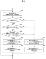
- Figure 6 shows a flowchart of object recognition.
- the camera is assumed to be a stereo camera, but is not particularly limited.
- the image comparison unit 34 determines whether the object is a reflective object or a luminescent object, and adds reflective/luminous object attributes.
- the attributes will be updated as needed until they are finalized. Since the object that can be detected in the illuminated image may be both a luminescent object and a reflective object, it is set to an indeterminate attribute and is set to be undetermined. Objects that can be detected in the unlit image are determined to be luminescent objects. Since the on/off attribute is added to the image, when one of the images taken at a certain time (t1) and the image taken at the previous time (t2) has the on attribute and the other has the off attribute, the image Make a comparison.
- the brightness images when the lights are on and off are compared, and objects that are detected both when the lights are off and when the lights are on are determined (extracted) as luminescent objects, and objects that are detected only when the lights are on are determined (extracted) as reflective objects.
- the types of these luminous objects and reflective objects are added as reflective/luminous object attributes (S36).
- the image comparison unit 34 compares a plurality of brightness images taken at consecutive times, calculates a movement vector from the difference in relative coordinates of the object, and adds it (S37).
- Objects include both reflective objects and luminescent objects.
- the movement vector is calculated by complementing and connecting the brightness images when the reflecting object is on.
- Each object holds as an attribute a movement vector between a certain time (t1) at which the image was taken and a time (t2) immediately before the image was taken.
- t1 time at which the image was taken
- t2 time immediately before the image was taken.
- the light is on at the time (t3) immediately before the time (t2), so the time (t2) and the time
- the relative position at time (t1) is predicted using the relative position at (t3).
- the pseudo object removal unit 41 removes them from among the objects that have reflective/luminous object attributes.
- An object whose movement vector is zero can be determined to be a pseudo object and removed (S38).
- pseudo objects that are objects that do not actually exist such as the reflection of the own vehicle's lights, can be eliminated. It is possible to exclude obstacles from light distribution control.
- the reflective object information is used to detect lanes using reflectors on guardrails on the roadside or delinators. improve rate.
- FIG. 7 shows a flowchart of the lane/road boundary detection unit 43.
- a brightness image is generated in the brightness image generation unit 32 of the image processing unit 20 (S41).
- the edge image generation unit 35 generates an edge image from the gradient of the luminance image (S42).
- the lane/road boundary detection unit 43 detects a lane from the edge image, and calculates a coordinate point according to a certain relative distance from the own vehicle (S43).
- the lane/road boundary detection unit 43 detects a reflective object with a reflective/luminous object attribute, a stationary object with a moving object attribute, and multiple objects detected at equal intervals in relative position from the own vehicle. It is extracted as a road boundary group (S44).
- S44 road boundary group
- reflective objects that are determined to be stationary objects by the lane/road boundary detection unit 43 are placed at equal intervals (at a fixed distance) relative to the host vehicle, they are determined to be a road boundary (group). to decide.
- whether to use lane detection information or road boundary groups is selected as lane information.
- the lane/road boundary detection unit 43 When a lane is detected on the screen (S45), the lane/road boundary detection unit 43 outputs the coordinate point of the lane detection as lane information (S46). If no lane is detected on the screen (S45), the lane/road boundary detection unit 43 outputs a coordinate point that is a certain distance closer to the own vehicle from the coordinates of the road boundary group as lane information (S47).
- Light distribution control is a technology that switches between high beam and low beam depending on the presence or absence of an object, such as high beam when there is no object and low beam when there is an object.
- a feature of the first embodiment of the present invention is that reflective objects including pseudo objects are excluded from light distribution control targets by using the reflection/emission object attributes of the recognition target (pseudo objects removal section 41).
- the light distribution control of the headlights is finely switched between high beam and low beam, the driver will feel uncomfortable, so in order to improve the accuracy of obstacle detection, objects are accumulated from multiple images and saved (S51).
- the presence or absence of the same object in multiple images is checked (S52). If there are identical objects, the reflective/luminous object attributes of the objects are used, and if they are reflective objects, they are treated as if they do not exist (S53). Further, if the object is not a reflective object (S53), it is determined whether the same object is a headlight or taillight of another vehicle detected by the light distribution light detection unit 44 (S54).
- the light distribution instruction unit 71 When the three conditions (S52, S53, S54) are satisfied, it is determined that there is a valid object that should be set to low beam, and the light distribution instruction unit 71 generates a light distribution instruction to set low beam, and the headlight unit A light distribution instruction is sent to 10 (S55).
- the light distribution control section 29 of the headlight section 10 controls the headlights to be set to low beam (S56).
- the light distribution instruction unit 71 generates a light distribution instruction to set the high beam, and sends the light distribution instruction to the headlight unit 10 (S57).
- the light distribution control section 29 of the headlight section 10 controls the headlights to be set to high beam (S58).
- the reflective object determination conditions (S53) and target object determination conditions (S54) for light distribution control can be changed and expanded.
- the light-emitting object is the headlight or taillight of another vehicle, but if the attribute of a pedestrian or bicycle is to be added, then the condition should be added when a reflective object such as a pedestrian or bicycle is detected. You can also do that.
- Figure 9 shows a flowchart of automatic emergency brake control.
- the camera control unit 3 sends reflective/luminescent object attributes, relative position attributes, and moving object attributes as object information for recognition (S61).
- the automatic emergency brake control section 25 uses the accumulated object information to predict the trajectory of the obstacle in the obstacle trajectory calculation section 60 (S62).
- the obstacle trajectory calculation unit 60 predicts the trajectory of the light-emitting object using the relative position information of the object information based on the reflective/light-emitting object attribute, and the trajectory of the light-emitting object determined based on the reflective/light-emitting object attribute during the lights-out period. Since it cannot be detected and the relative position is unknown, the trajectory is predicted by predicting the position using linear interpolation or polynomial interpolation from the relative positions of multiple times back (S63).
- the reflecting object corresponds to both stationary objects and moving objects, so the moving object attribute is not used.
- a stationary object with the moving object attribute may be treated as the target object's trajectory, skipping trajectory prediction and treated as stationary, and calculate the relative position of the own vehicle with respect to the own vehicle trajectory.
- the obstacle trajectory calculation unit 60 determines that the moving object is a pedestrian or a bicycle based on the relative speed of the own vehicle, and calculates the future trajectory based on the past trajectory. Predict the trajectory.
- the risk calculation unit 61 calculates whether the trajectory of the light-emitting object and the reflective object is on the path of the own vehicle, and calculates the risk of collision (S64).
- the control unit 62 issues a warning or an emergency brake control instruction based on the collision risk calculated by the risk calculation unit 61 (when it is determined that the risk of collision with the host vehicle is high) (S65). Thereafter, the brake unit 13 of the actuator receives the emergency brake control instruction via the CAN 6, and performs brake control of the own vehicle based on the control instruction.
- FIG. 10 shows a flowchart of automatic lane departure control.
- the camera control unit 3 sends out reflective/luminous object attributes, relative position attributes, moving object attributes, and recognition lane information as recognition object information (S71).
- the own vehicle trajectory calculation unit 52 predicts the trajectory of the own vehicle from the steering information of the own vehicle (S72).
- the deviation determination unit 53 inputs the trajectory predicted from the steering information and the recognized lane information, and calculates the risk of deviating from the lane (S73).
- the control unit 51 issues a warning or a steering control instruction to avoid lane departure (to prevent entry into the road boundary) (S74).
- the steering unit 12 of the actuator receives the steering control instruction via the CAN 6, and performs steering control of the own vehicle based on the control instruction.
- the principle of the second embodiment is shown in FIG. It is assumed that there are two cycles, and the ratio of lights off and lights on in the first cycle is 1:9, and the ratio of lights off and lights on in the second cycle is 1:4. That is, the headlights are turned on and off periodically at different duties (1:9 in the first cycle, 1:4 in the second cycle).
- the imaging timing of the camera is also variable according to the two-cycle on/off duty. By performing phase adjustment, in the first cycle, images are taken twice when the lights are off, and six times when the lights are on, and in the second cycle, images are taken three times when the lights are off, and five times when the lights are on. Repeat this cycle. Two cycles is one example; by using a multi-duty system with three or four cycles and multiple cycles, the possibility of synchronization with other vehicles can be significantly reduced.
- the first embodiment and second embodiment of the present invention can also be expanded as follows.
- the headlight turn-off duty calculation of the recognition unit 21 can be set variably instead of fixedly in the light-off duty calculation unit 40.
- the light-off duty it can be set based on a random number when the ignition is turned on, for example. Further, in order to reduce the frequency of turning off the headlights, it is also possible to turn off the headlights only during a specific period or at a specific location based on the map information of the map section 11.
- the camera control device (camera control section 3) of this embodiment is a camera that controls the headlight section 10 that illuminates the front of the own vehicle and the camera imaging section 2 that takes an image of the front of the own vehicle.
- the camera control device sets a lighting/extinguishing pattern of a predetermined frequency and duty in the headlight section 10 (duty instruction section 70), and turns on/off using the lighting/extinguishing pattern.
- the headlight unit 10 (light distribution) is controlled (light distribution instruction unit 71), and the camera imaging unit 2 receives a periodic first signal based on a predetermined frequency and duty for the headlight unit 10.
- An imaging timing pattern different from the lighting/extinguishing pattern is set for an imaging time interval of 1 and a second imaging time interval shorter than the first imaging time interval (imaging timing calculation unit 30), and the imaging timing pattern of the camera imaging unit 2 is set.
- imaging timing calculation unit 30 By adjusting the time phase (imaging phase) of the timing pattern, the imaging time interval when the headlight section 10 is switched between turning off and turning on is reduced (shortened) (imaging phase adjustment section 31).
- the camera control device adjusts the imaging timing pattern of the camera imaging unit 2 based on the number of images at the time of lighting and the number of images at the time of turning off of each image captured by the camera imaging unit 2 with the time phase shifted. Adjust the time phase (imaging phase adjustment section 31).
- the camera control device measures the brightness of a specific pixel of each image captured by the camera imaging unit 2 while shifting the time phase, determines an image when the light is on and an image when the light is off based on the luminance, and
- the time phase of the imaging timing pattern of the camera imaging unit 2 is adjusted by checking the number of images when the light is on and the number of images when the light is off periodically at the shutter timing in the time phase (imaging phase adjustment unit 31). .
- the camera control device compares a first brightness image and a second brightness image obtained by turning off and turning on the headlight unit 10 captured by the camera imaging unit 2, extracts a reflective object, and generates a plurality of brightness images.
- the moving vector of the reflecting object in the image is calculated by comparing the moving vectors of the reflecting object, and when the moving vector of the reflecting object is opposite to the moving vector of the own vehicle, the reflecting object is regarded as a stationary object and the moving vector of the reflecting object is zero.
- the reflective object is determined to be a pseudo object, and in all other cases, the reflective object is determined to be a moving object (luminance image generation section 32, image comparison section 34, pseudo object removal section 41, and moving object determination section 42).
- the camera control device variably sets the duty of the headlight section 10 (light-off duty calculation section 40).
- the camera control device sets the duty of the headlight unit 10 based on a random number (light-off duty calculation unit 40).
- the camera control device periodically turns on and off the headlight section 10 at different duties a plurality of times (light-off duty calculation section 40, duty instruction section 70, light distribution instruction section 71).
- the camera control device causes the headlight section 10 to be turned off only during a specific period or at a specific location based on the map information (lights-off duty calculation section 40).
- the camera control device excludes the pseudo object of the reflective object from the obstacle target of the light distribution control. removal section 41, light distribution instruction section 71).
- the vehicle control device (vehicle control unit 4) of this embodiment is a vehicle control device that controls the own vehicle based on information output from the camera control device, and the vehicle control device controls the own vehicle based on the information output from the camera control device. If the reflective object is the moving object, it is determined that the moving object is a pedestrian or a bicycle based on the relative speed of the vehicle, the future trajectory is predicted from the past trajectory, and the vehicle The risk of a collision with the own vehicle is calculated, and when it is determined that the risk of a collision with the own vehicle is high, a warning or automatic emergency brake control is performed (automatic emergency brake control unit 25).
- control lines and information lines are shown that are considered necessary for explanation, and not all control lines and information lines are necessarily shown in the product. In reality, almost all components may be considered to be interconnected.
- Pseudo object removal unit 42 Moving object determination unit 43... Lane/road boundary detection unit 44... Light distribution light detection unit 51, 62... Control unit 52... Self-vehicle Trajectory calculation unit 53... Deviation determination unit 60... Obstacle trajectory calculation unit 61... Risk calculation unit 70... Duty instruction unit 71... Light distribution instruction unit 100... Oncoming vehicle at time t1 Headlights 101...Reflection on a reflective object on the curb at time t1 102...Reflection on a reflective object on a guardrail at time t1 103...Reflection on the own vehicle's headlight at time t1 (pseudo object) 104... Headlight of an oncoming vehicle at time t2 111...
- Reflective object of a bicycle in the roadway at time t1 For example, Reflective object of a bicycle in the roadway at time t1; Reflective object of a stationary object outside the roadway at time t1 113... Inside the roadway at time t1 Pseudo object 114 due to the reflection of the headlights...Reflection object 115 of a bicycle on the roadway at time t2...Reflection object 116 of a stationary object outside the roadway at time t2...Reflection of the headlights on the roadway at time t2 Pseudo object due to reflection 117...Movement vector of the reflective object of the bicycle on the roadway at time t2-t1...Movement vector of the reflective object of a stationary object outside the roadway at time t2-t1...Time t2- Movement vector of the pseudo object due to reflection of headlights in the roadway at t1
Landscapes
- Engineering & Computer Science (AREA)
- Multimedia (AREA)
- Signal Processing (AREA)
- Lighting Device Outwards From Vehicle And Optical Signal (AREA)
Priority Applications (3)
| Application Number | Priority Date | Filing Date | Title |
|---|---|---|---|
| JP2024528298A JP7745101B2 (ja) | 2022-06-17 | 2023-03-08 | カメラ制御装置及び車両制御装置 |
| DE112023000647.4T DE112023000647T5 (de) | 2022-06-17 | 2023-03-08 | Kamerasteuervorrichtung und fahrzeugsteuervorrichtung |
| CN202380027972.7A CN119032578A (zh) | 2022-06-17 | 2023-03-08 | 摄像机控制装置及车辆控制装置 |
Applications Claiming Priority (2)
| Application Number | Priority Date | Filing Date | Title |
|---|---|---|---|
| JP2022097965 | 2022-06-17 | ||
| JP2022-097965 | 2022-06-17 |
Publications (1)
| Publication Number | Publication Date |
|---|---|
| WO2023243162A1 true WO2023243162A1 (ja) | 2023-12-21 |
Family
ID=89192563
Family Applications (1)
| Application Number | Title | Priority Date | Filing Date |
|---|---|---|---|
| PCT/JP2023/008918 Ceased WO2023243162A1 (ja) | 2022-06-17 | 2023-03-08 | カメラ制御装置及び車両制御装置 |
Country Status (4)
| Country | Link |
|---|---|
| JP (1) | JP7745101B2 (https=) |
| CN (1) | CN119032578A (https=) |
| DE (1) | DE112023000647T5 (https=) |
| WO (1) | WO2023243162A1 (https=) |
Citations (4)
| Publication number | Priority date | Publication date | Assignee | Title |
|---|---|---|---|---|
| JP2007076429A (ja) * | 2005-09-13 | 2007-03-29 | Koito Mfg Co Ltd | ヘッドランプシステム |
| JP2010235045A (ja) * | 2009-03-31 | 2010-10-21 | Toyota Central R&D Labs Inc | 照明制御装置及びプログラム |
| JP2011205619A (ja) * | 2010-01-29 | 2011-10-13 | Shinsedai Kk | 画像処理装置、画像処理方法、コンピュータプログラム、及び、電子機器 |
| JP2011209961A (ja) * | 2010-03-29 | 2011-10-20 | Kyocera Corp | 車載用撮像装置 |
Family Cites Families (2)
| Publication number | Priority date | Publication date | Assignee | Title |
|---|---|---|---|---|
| JPH0742717B2 (ja) | 1991-06-28 | 1995-05-10 | 照文 郷戸 | 便状廃棄物処理装置 |
| JP5415237B2 (ja) | 2009-11-25 | 2014-02-12 | 株式会社小糸製作所 | 車両用前照灯システム |
-
2023
- 2023-03-08 JP JP2024528298A patent/JP7745101B2/ja active Active
- 2023-03-08 CN CN202380027972.7A patent/CN119032578A/zh active Pending
- 2023-03-08 WO PCT/JP2023/008918 patent/WO2023243162A1/ja not_active Ceased
- 2023-03-08 DE DE112023000647.4T patent/DE112023000647T5/de active Pending
Patent Citations (4)
| Publication number | Priority date | Publication date | Assignee | Title |
|---|---|---|---|---|
| JP2007076429A (ja) * | 2005-09-13 | 2007-03-29 | Koito Mfg Co Ltd | ヘッドランプシステム |
| JP2010235045A (ja) * | 2009-03-31 | 2010-10-21 | Toyota Central R&D Labs Inc | 照明制御装置及びプログラム |
| JP2011205619A (ja) * | 2010-01-29 | 2011-10-13 | Shinsedai Kk | 画像処理装置、画像処理方法、コンピュータプログラム、及び、電子機器 |
| JP2011209961A (ja) * | 2010-03-29 | 2011-10-20 | Kyocera Corp | 車載用撮像装置 |
Also Published As
| Publication number | Publication date |
|---|---|
| DE112023000647T5 (de) | 2025-03-06 |
| JP7745101B2 (ja) | 2025-09-26 |
| CN119032578A (zh) | 2024-11-26 |
| JPWO2023243162A1 (https=) | 2023-12-21 |
Similar Documents
| Publication | Publication Date | Title |
|---|---|---|
| JP4253271B2 (ja) | 画像処理システム及び車両制御システム | |
| US10552688B2 (en) | Method and device for detecting objects in the surroundings of a vehicle | |
| JP4253275B2 (ja) | 車両制御システム | |
| CN103249597B (zh) | 车辆配光控制装置以及方法 | |
| JP7381388B2 (ja) | 信号灯状態識別装置、信号灯状態識別方法及び信号灯状態識別用コンピュータプログラムならびに制御装置 | |
| JP4538468B2 (ja) | 画像処理装置,画像処理方法、及び画像処理システム | |
| EP3517363A1 (en) | Vehicle headlight control device | |
| CN102470793B (zh) | 用于光特征变化的基于间距的去抖动的方法和装置 | |
| CN115151955A (zh) | 用于监控机动车辆的环境的系统 | |
| EP2525302A1 (en) | Image processing system | |
| US20140347872A1 (en) | Method and device for recognizing an illuminated roadway ahead of a vehicle | |
| JP5251680B2 (ja) | 照明制御装置及びプログラム | |
| RU2760074C1 (ru) | Способ управления фарами и устройство управления фарами | |
| JP7793072B2 (ja) | 前照灯制御装置及び前照灯制御方法 | |
| JP7745101B2 (ja) | カメラ制御装置及び車両制御装置 | |
| WO2019156087A1 (ja) | 画像処理装置および車両用灯具 | |
| CN112565618B (zh) | 曝光控制装置 | |
| JP7084223B2 (ja) | 画像処理装置および車両用灯具 | |
| JP6335065B2 (ja) | 車外環境認識装置 | |
| CN110774976A (zh) | 用于控制车辆前灯的装置和方法 | |
| JP6539191B2 (ja) | 車外環境認識装置 | |
| JP6549974B2 (ja) | 車外環境認識装置 | |
| WO2019044434A1 (ja) | 物体検出システム | |
| US12028621B2 (en) | Object detection system for a motor vehicle | |
| JP6278217B1 (ja) | 車両用ヘッドライト制御装置 |
Legal Events
| Date | Code | Title | Description |
|---|---|---|---|
| 121 | Ep: the epo has been informed by wipo that ep was designated in this application |
Ref document number: 23823466 Country of ref document: EP Kind code of ref document: A1 |
|
| ENP | Entry into the national phase |
Ref document number: 2024528298 Country of ref document: JP Kind code of ref document: A |
|
| WWE | Wipo information: entry into national phase |
Ref document number: 202380027972.7 Country of ref document: CN |
|
| WWE | Wipo information: entry into national phase |
Ref document number: 112023000647 Country of ref document: DE |
|
| WWP | Wipo information: published in national office |
Ref document number: 112023000647 Country of ref document: DE |
|
| 122 | Ep: pct application non-entry in european phase |
Ref document number: 23823466 Country of ref document: EP Kind code of ref document: A1 |