WO2023242915A1 - 無線通信装置及び無線通信方法 - Google Patents
無線通信装置及び無線通信方法 Download PDFInfo
- Publication number
- WO2023242915A1 WO2023242915A1 PCT/JP2022/023661 JP2022023661W WO2023242915A1 WO 2023242915 A1 WO2023242915 A1 WO 2023242915A1 JP 2022023661 W JP2022023661 W JP 2022023661W WO 2023242915 A1 WO2023242915 A1 WO 2023242915A1
- Authority
- WO
- WIPO (PCT)
- Prior art keywords
- links
- wireless communication
- sleep
- communication device
- delay time
- Prior art date
- Legal status (The legal status is an assumption and is not a legal conclusion. Google has not performed a legal analysis and makes no representation as to the accuracy of the status listed.)
- Ceased
Links
Images




Classifications
-
- H—ELECTRICITY
- H04—ELECTRIC COMMUNICATION TECHNIQUE
- H04W—WIRELESS COMMUNICATION NETWORKS
- H04W74/00—Wireless channel access
- H04W74/08—Non-scheduled access, e.g. ALOHA
-
- H—ELECTRICITY
- H04—ELECTRIC COMMUNICATION TECHNIQUE
- H04W—WIRELESS COMMUNICATION NETWORKS
- H04W84/00—Network topologies
- H04W84/02—Hierarchically pre-organised networks, e.g. paging networks, cellular networks, WLAN [Wireless Local Area Network] or WLL [Wireless Local Loop]
- H04W84/10—Small scale networks; Flat hierarchical networks
- H04W84/12—WLAN [Wireless Local Area Networks]
-
- Y—GENERAL TAGGING OF NEW TECHNOLOGICAL DEVELOPMENTS; GENERAL TAGGING OF CROSS-SECTIONAL TECHNOLOGIES SPANNING OVER SEVERAL SECTIONS OF THE IPC; TECHNICAL SUBJECTS COVERED BY FORMER USPC CROSS-REFERENCE ART COLLECTIONS [XRACs] AND DIGESTS
- Y02—TECHNOLOGIES OR APPLICATIONS FOR MITIGATION OR ADAPTATION AGAINST CLIMATE CHANGE
- Y02D—CLIMATE CHANGE MITIGATION TECHNOLOGIES IN INFORMATION AND COMMUNICATION TECHNOLOGIES [ICT], I.E. INFORMATION AND COMMUNICATION TECHNOLOGIES AIMING AT THE REDUCTION OF THEIR OWN ENERGY USE
- Y02D30/00—Reducing energy consumption in communication networks
- Y02D30/70—Reducing energy consumption in communication networks in wireless communication networks
Definitions
- the present disclosure relates to a wireless communication device and a wireless communication method.
- IEEE 802.11be a wireless LAN communication standard, is equipped with a multi-link transmission function that allows multiple frequency bands to be used together. Multilink transmission allows different data to be transmitted simultaneously in multiple frequency bands, thereby achieving higher speeds. Furthermore, each link used in multilink transmission implements CSMA/CA.
- IEEE 802.11be standardization document IEEE 802.11-20/1935r64, “Compendium of straw polls and potential changes to the Specification Framework Document”, “6 Multi-link operation” (https://mentor.ieee.org/802.11/dcn/ 20/11-20-1935-64-00be-compendium-of-straw-polls-and-potential-changes-to-the-specification-framework-document-part-2.docx)
- the present disclosure solves the above-mentioned problems by putting some links to sleep for a certain period of time when there is little data or when data quality requirements are met. Thereby, it is an object of the present invention to provide a wireless communication device and a wireless communication method that can reduce power consumption and improve transmission efficiency.
- a first aspect of the present disclosure is a wireless communication device that accommodates at least one traffic flow and performs multilink transmission using a plurality of links, the wireless communication device compares delay time requirements of each of the traffic flows, A function that determines the conditions, a function that predicts the total delay time for all combinations of links to be put to sleep, and a function that compares the delay conditions and the total delay time for all combinations and determines whether or not the combination of links allows sleep. It is preferable that the wireless communication device has a function of making a determination, a function of selecting a combination of links to be put to sleep based on the result of the determination, and a function of performing wireless communication based on the determined combination of links.
- a second aspect of the present disclosure is a wireless communication method performed by a wireless communication device that accommodates at least one traffic flow and performs multilink transmission using a plurality of links, the method comprising: A process of comparing requirements and determining delay conditions, a process of estimating the total delay time for all combinations of links to be put to sleep, and a process of comparing delay conditions and total delay time for all combinations to determine the links that can be put to sleep. a step of determining whether or not a combination of links exists, a step of determining a combination of links to be put to sleep from the result of the determination, and a step of performing wireless communication based on the determined combination of links. preferable.
- some links when there is little data or when data quality requirements are met, some links can be put to sleep for a certain period of time to reduce power consumption and improve transmission efficiency. can be achieved.
- FIG. 1 is a diagram illustrating conventional multilink transmission
- FIG. FIG. 2 is a diagram illustrating multilink transmission according to Embodiment 1 of the present disclosure.
- 2 is a flowchart illustrating a process in which an AP determines a delay condition according to Embodiment 1 of the present disclosure.
- 2 is a flowchart illustrating a process of estimating the total delay time when the AP goes into link sleep according to Embodiment 1 of the present disclosure. It is a flow which shows the process which determines the link in which AP sleeps based on Embodiment 1 of this indication.
- FIG. 2 is a functional block diagram of an AP according to Embodiment 1 of the present disclosure.
- FIG. 1 is a diagram illustrating conventional multilink transmission. First, a process for transmitting information from one device to another device used in multilink will be explained.
- the multi-link 200 includes an MLD (Multi Link Device) 2.
- the MLD 2 has a MAC (Multi Access Controller) 3.
- the MAC 3 is a controller that performs communication control, and transmits information transmitted from a higher level to APs (Access Points) 4a, 4b, and 4c.
- the AP 4a converts the transmitted information into a packet 6a and transmits it to the MLD 10 via the link 8a.
- the AP 4b converts the transmitted information into a packet 6b and transmits it to the MLD 10 via the link 8b.
- the AP 4c converts the transmitted information into a packet 6c and transmits it to the MLD 10 via a link 8c.
- the MLD 10 receives packets 6a, 6b, and 6c at the STAs 12a, 12b, and 12c, respectively.
- the STA 12a transmits the information included in the packet 6a to the MAC 14.
- the STA 12b transmits the information included in the packet 6b to the MAC 14.
- the STA 12c transmits the information included in the packet 6c to the MAC 14.
- the MAC 14 transmits the received information to a higher level.
- FIG. 2 is a diagram showing multilink transmission according to Embodiment 1 of the present disclosure.
- the multi-link transmission of this embodiment puts some links to sleep for a certain period of time when there is little data or when data quality requirements are met.
- the multilink 100 includes an MLD2.
- MLD2 has MAC3.
- the MAC 3 transmits information transmitted from the upper level to the APs 4a, 4b, and 4c.
- the APs 4a, 4b, and 4c determine the link to be used by performing predetermined processing. Multilink transmission is then performed using only the determined links. The details of the predetermined processing will be described later.
- FIG. 2 shows a case where information is transmitted using only the link 8a. That is, the AP 4a converts the transmitted information into packets 6a, 6b, and 6c, and transmits them to the MLD 10 via the link 8a. Links 8b and 8c go into a sleep state.
- the MLD 10 receives packets 6a, 6b, and 6c at the STA 12a.
- the STA 12a transmits the information contained in packets 6a, 6b, and 6c to the MAC 14.
- the MAC 14 transmits the received information to a higher level.
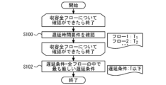
- FIG. 3 is a flowchart showing a process in which the AP determines a delay condition according to Embodiment 1 of the present disclosure.
- the delay time is determined from the delay time requirements inherent to each traffic flow.
- step 100 the AP checks the delay time requirements.
- the multilink transmission in question accommodates n traffic flows.
- delay time requirements are checked for all accommodated flows.
- step 102 the AP determines the delay conditions.
- the delay condition a case is shown in which the strictest delay time requirement of all flows is selected as the delay condition. This determines the delay conditions for the target multilink transmission.
- FIG. 4 is a flowchart showing a process for estimating the total delay time when the AP goes into link sleep according to Embodiment 1 of the present disclosure.
- the AP estimates the total delay time d n that would occur if a particular link were put to sleep.
- the total delay time d n is defined as the sum of the transmission time T n and the queuing time Q n .
- the transmission time T n is the channel use time of the own station, and is determined from MCS (Modulation and Coding Scheme) or the like.
- the queuing time Qn is the waiting time due to channel use by other stations, and is determined based on the degree of interference and the like. Furthermore, this prediction is performed for all combinations of all links included in the target multilink.
- One example of a method for predicting the total delay time d n is to add the transmission time T n of a link that has been put to sleep to the transmission time T n of a link that has not been put to sleep. For example, consider a case where link 8a in multilink 100 is put to sleep. In this case, the packet 6b flowing on the link 8a will be transmitted using the link 8b or link 8c. Therefore, the transmission time Tn of link 8a is added to the transmission time Tn of link 8b or link 8c. Thereby, the total delay time d n of link 8b and link 8c can be predicted.
- FIG. 5 is a flowchart illustrating a process for determining a link on which an AP sleeps, according to Embodiment 1 of the present disclosure.
- step 106 it is investigated whether the expected total delay time d n satisfies the delay condition. This investigation is performed on one combination of all links included in the target multilink. If the conditions are met, proceed to step 108. If the conditions are not met, proceed to step 110.
- step 108 the investigated combination of links is determined to be a combination that allows sleep, and is stored. Thereafter, the process returns to step 106 to investigate the next link combination.
- step 110 the investigated combination of links is determined to be a combination in which sleep is not possible and is stored. Thereafter, the process returns to step 106 to investigate the next link combination.
- step 112 the link combination with the largest number of links is selected from among the link combinations determined to be sleep-enabled combinations. Then, it is decided to put that combination of links to sleep.
- the first method is to select based on the total delay time d n . For example, by selecting a combination of links with the shortest total delay time d n , it is possible to perform multilink transmission that is most excellent in terms of total delay time. Note that depending on other requirements, it is also possible to select a combination of links in which the length of the total delay time d n is in an arbitrary order.
- the second method is to select based on transmission efficiency. For example, by selecting a combination of links with the best transmission efficiency, it is possible to perform multi-link transmission that is most excellent in terms of transmission efficiency. Note that depending on other requirements, it is also possible to select a combination of links that have an arbitrary ranking of transmission efficiency.
- the third method is to select based on the number of links to be used. For example, by selecting a combination of links that uses the least number of links, it is possible to put the maximum number of terminals to sleep, and therefore it is possible to perform multi-link transmission that is most excellent in terms of power consumption. Note that depending on other requirements, it is also possible to select a combination of links in which the number of links used is in an arbitrary order.
- the delay condition is 8 ms or less for flow 1.
- the transmission time of link 1, 2 ms is distributed to link 2 and link 3. That is, the total delay time of each link is as shown in Table 3. In this case, the total delay time for the entire multilink is the longest, 7 ms.
- multilink transmission is performed using all links and traffic flows. That is, three links and four traffic flows perform multi-link transmission using 12 transmitting and receiving circuits.
- link 1 is used to perform multilink transmission. That is, one link and four traffic flows perform multi-link transmission using four transmitting/receiving circuits.
- multi-link transmission can be performed using two-thirds of the transmitting and receiving circuits compared to the conventional example. As a result, reduction in power consumption and improvement in transmission efficiency can be achieved.
- FIG. 6 is a functional block diagram of the AP according to Embodiment 1 of the present disclosure.
- the AP 4 includes a wired NW connection function 16.
- the wired NW connection function 16 transmits the information transmitted from the MAC 3 to the transmission data distribution function 18.
- the transmission data distribution function 18 determines the link to sleep by performing the above-described predetermined processing. If AP4 is connected to a sleeping link, AP4 will be in a standby state. If the AP 4 is not connected to the sleep link, the transmission data distribution function 18 transmits the information transmitted from the MAC 3 to the access right acquisition function 20 .
- the access right acquisition function 20 implements CSMA/CA. If the access right can be obtained by CSMA/CA, the data transmission function 22 to the wireless medium performs wireless communication. As a result, multilink transmission is performed.
Landscapes
- Engineering & Computer Science (AREA)
- Computer Networks & Wireless Communication (AREA)
- Signal Processing (AREA)
- Mobile Radio Communication Systems (AREA)
Priority Applications (3)
| Application Number | Priority Date | Filing Date | Title |
|---|---|---|---|
| PCT/JP2022/023661 WO2023242915A1 (ja) | 2022-06-13 | 2022-06-13 | 無線通信装置及び無線通信方法 |
| JP2024527918A JP7827144B2 (ja) | 2022-06-13 | 2022-06-13 | 無線通信装置及び無線通信方法 |
| US19/025,309 US20260027436A1 (en) | 2022-06-13 | 2025-01-16 | Fencing reaction time training assembly and method of use |
Applications Claiming Priority (1)
| Application Number | Priority Date | Filing Date | Title |
|---|---|---|---|
| PCT/JP2022/023661 WO2023242915A1 (ja) | 2022-06-13 | 2022-06-13 | 無線通信装置及び無線通信方法 |
Related Child Applications (2)
| Application Number | Title | Priority Date | Filing Date |
|---|---|---|---|
| US18873791 A-371-Of-International | 2022-06-13 | ||
| US19/025,309 Continuation-In-Part US20260027436A1 (en) | 2022-06-13 | 2025-01-16 | Fencing reaction time training assembly and method of use |
Publications (1)
| Publication Number | Publication Date |
|---|---|
| WO2023242915A1 true WO2023242915A1 (ja) | 2023-12-21 |
Family
ID=89192604
Family Applications (1)
| Application Number | Title | Priority Date | Filing Date |
|---|---|---|---|
| PCT/JP2022/023661 Ceased WO2023242915A1 (ja) | 2022-06-13 | 2022-06-13 | 無線通信装置及び無線通信方法 |
Country Status (2)
| Country | Link |
|---|---|
| JP (1) | JP7827144B2 (https=) |
| WO (1) | WO2023242915A1 (https=) |
Citations (1)
| Publication number | Priority date | Publication date | Assignee | Title |
|---|---|---|---|---|
| JP2011146784A (ja) * | 2010-01-12 | 2011-07-28 | Nippon Telegr & Teleph Corp <Ntt> | 光加入者線終端装置 |
Family Cites Families (2)
| Publication number | Priority date | Publication date | Assignee | Title |
|---|---|---|---|---|
| JP7168082B2 (ja) * | 2019-06-10 | 2022-11-09 | 日本電信電話株式会社 | 無線通信システム、無線通信方法および無線局装置 |
| US20230354186A1 (en) * | 2020-07-27 | 2023-11-02 | Nippon Telegraph And Telephone Corporation | Base station and terminal apparatus |
-
2022
- 2022-06-13 JP JP2024527918A patent/JP7827144B2/ja active Active
- 2022-06-13 WO PCT/JP2022/023661 patent/WO2023242915A1/ja not_active Ceased
Patent Citations (1)
| Publication number | Priority date | Publication date | Assignee | Title |
|---|---|---|---|---|
| JP2011146784A (ja) * | 2010-01-12 | 2011-07-28 | Nippon Telegr & Teleph Corp <Ntt> | 光加入者線終端装置 |
Non-Patent Citations (1)
| Title |
|---|
| RONNY YONGHO KIM (KNUT): "Issues on MLD Power Saving", IEEE DRAFT; 11-20-1402-01-00BE-ISSUES-ON-MLD-POWER-SAVING, IEEE-SA MENTOR, PISCATAWAY, NJ USA, vol. 802.11 EHT; 802.11be, no. 1, 28 October 2020 (2020-10-28), Piscataway, NJ USA , pages 1 - 13, XP068174070 * |
Also Published As
| Publication number | Publication date |
|---|---|
| JP7827144B2 (ja) | 2026-03-10 |
| JPWO2023242915A1 (https=) | 2023-12-21 |
Similar Documents
| Publication | Publication Date | Title |
|---|---|---|
| US11889557B2 (en) | Wireless communication system, wireless communication method, wireless LAN access point, and wireless LAN station | |
| US7738374B2 (en) | Channel allocation for access point in mesh network | |
| RU2391798C2 (ru) | Использование сообщений использования ресурсов в мас с множеством несущих для достижения равноправности | |
| Wen et al. | QoS-aware mode selection and resource allocation scheme for device-to-device (D2D) communication in cellular networks | |
| US10264592B2 (en) | Method and radio network node for scheduling of wireless devices in a cellular network | |
| US20090059877A1 (en) | Wireless communication device and method for controlling wireless communication device | |
| US8934361B2 (en) | Downlink inter-cell interference coordination method and eNB | |
| CN102017768A (zh) | 用于多载波通信系统中的频率再用的方法和设备 | |
| Ko et al. | Joint optimization of channel selection and frame scheduling for coexistence of LTE and WLAN | |
| CN101755476A (zh) | 链路适配方案 | |
| WO2012174916A1 (zh) | 异系统间频谱共享情况下的干扰抑制方法和设备 | |
| US7899459B2 (en) | Call admission control device and call admission control method | |
| Elgendi et al. | Traffic offloading for 5G: L-LTE or Wi-Fi | |
| Vučević et al. | Reinforcement learning for joint radio resource management in LTE-UMTS scenarios | |
| Merlhe et al. | Hybrid joint-transmission multi-point coordination for inter-cell interference management | |
| JP7827144B2 (ja) | 無線通信装置及び無線通信方法 | |
| RU2364043C2 (ru) | Согласованное автономное и запланированное выделение ресурсов в распределенной системе связи | |
| Zeinali et al. | AI-based radio resource and transmission opportunity allocation for 5G-V2X hetnets: NR and NR-U networks | |
| CN104429131A (zh) | 选择无线接入网络的方法和装置 | |
| Ruan et al. | Efficient traffic scheduling for coexistence of eMBB and uRLLC in industrial IoT networks | |
| JP7772213B2 (ja) | 無線通信システム、無線通信方法及び無線通信装置 | |
| Chao et al. | Cooperative spectrum sharing and scheduling in self-organizing femtocell networks | |
| Alorainy | Buffer-aware packet scheduling in multi-flow carrier aggregation | |
| Ge et al. | Access point selection for WLANs with cognitive radio: A restless bandit approach | |
| Zalghout et al. | Optimizing context-aware resource and network assignment in heterogeneous wireless networks |
Legal Events
| Date | Code | Title | Description |
|---|---|---|---|
| 121 | Ep: the epo has been informed by wipo that ep was designated in this application |
Ref document number: 22946735 Country of ref document: EP Kind code of ref document: A1 |
|
| WWE | Wipo information: entry into national phase |
Ref document number: 2024527918 Country of ref document: JP |
|
| WWE | Wipo information: entry into national phase |
Ref document number: 18873791 Country of ref document: US |
|
| NENP | Non-entry into the national phase |
Ref country code: DE |
|
| 122 | Ep: pct application non-entry in european phase |
Ref document number: 22946735 Country of ref document: EP Kind code of ref document: A1 |