WO2023242915A1 - 無線通信装置及び無線通信方法 - Google Patents
無線通信装置及び無線通信方法 Download PDFInfo
- Publication number
- WO2023242915A1 WO2023242915A1 PCT/JP2022/023661 JP2022023661W WO2023242915A1 WO 2023242915 A1 WO2023242915 A1 WO 2023242915A1 JP 2022023661 W JP2022023661 W JP 2022023661W WO 2023242915 A1 WO2023242915 A1 WO 2023242915A1
- Authority
- WO
- WIPO (PCT)
- Prior art keywords
- links
- wireless communication
- sleep
- communication device
- delay time
- Prior art date
Links
- 238000004891 communication Methods 0.000 title claims abstract description 34
- 238000000034 method Methods 0.000 title claims abstract description 26
- 230000005540 biological transmission Effects 0.000 claims abstract description 58
- 230000007958 sleep Effects 0.000 claims abstract description 41
- 101100172132 Mus musculus Eif3a gene Proteins 0.000 description 8
- 238000010586 diagram Methods 0.000 description 6
- 238000005315 distribution function Methods 0.000 description 3
- 238000011835 investigation Methods 0.000 description 3
- 108091023231 Ap4A Proteins 0.000 description 2
- 238000010187 selection method Methods 0.000 description 1
- 239000010902 straw Substances 0.000 description 1
Images


Classifications
-
- H—ELECTRICITY
- H04—ELECTRIC COMMUNICATION TECHNIQUE
- H04W—WIRELESS COMMUNICATION NETWORKS
- H04W74/00—Wireless channel access
- H04W74/08—Non-scheduled access, e.g. ALOHA
-
- H—ELECTRICITY
- H04—ELECTRIC COMMUNICATION TECHNIQUE
- H04W—WIRELESS COMMUNICATION NETWORKS
- H04W84/00—Network topologies
- H04W84/02—Hierarchically pre-organised networks, e.g. paging networks, cellular networks, WLAN [Wireless Local Area Network] or WLL [Wireless Local Loop]
- H04W84/10—Small scale networks; Flat hierarchical networks
- H04W84/12—WLAN [Wireless Local Area Networks]
-
- Y—GENERAL TAGGING OF NEW TECHNOLOGICAL DEVELOPMENTS; GENERAL TAGGING OF CROSS-SECTIONAL TECHNOLOGIES SPANNING OVER SEVERAL SECTIONS OF THE IPC; TECHNICAL SUBJECTS COVERED BY FORMER USPC CROSS-REFERENCE ART COLLECTIONS [XRACs] AND DIGESTS
- Y02—TECHNOLOGIES OR APPLICATIONS FOR MITIGATION OR ADAPTATION AGAINST CLIMATE CHANGE
- Y02D—CLIMATE CHANGE MITIGATION TECHNOLOGIES IN INFORMATION AND COMMUNICATION TECHNOLOGIES [ICT], I.E. INFORMATION AND COMMUNICATION TECHNOLOGIES AIMING AT THE REDUCTION OF THEIR OWN ENERGY USE
- Y02D30/00—Reducing energy consumption in communication networks
- Y02D30/70—Reducing energy consumption in communication networks in wireless communication networks
Definitions
- the present disclosure relates to a wireless communication device and a wireless communication method.
- IEEE 802.11be a wireless LAN communication standard, is equipped with a multi-link transmission function that allows multiple frequency bands to be used together. Multilink transmission allows different data to be transmitted simultaneously in multiple frequency bands, thereby achieving higher speeds. Furthermore, each link used in multilink transmission implements CSMA/CA.
- IEEE 802.11be standardization document IEEE 802.11-20/1935r64, “Compendium of straw polls and potential changes to the Specification Framework Document”, “6 Multi-link operation” (https://mentor.ieee.org/802.11/dcn/ 20/11-20-1935-64-00be-compendium-of-straw-polls-and-potential-changes-to-the-specification-framework-document-part-2.docx)
- the present disclosure solves the above-mentioned problems by putting some links to sleep for a certain period of time when there is little data or when data quality requirements are met. Thereby, it is an object of the present invention to provide a wireless communication device and a wireless communication method that can reduce power consumption and improve transmission efficiency.
- a first aspect of the present disclosure is a wireless communication device that accommodates at least one traffic flow and performs multilink transmission using a plurality of links, the wireless communication device compares delay time requirements of each of the traffic flows, A function that determines the conditions, a function that predicts the total delay time for all combinations of links to be put to sleep, and a function that compares the delay conditions and the total delay time for all combinations and determines whether or not the combination of links allows sleep. It is preferable that the wireless communication device has a function of making a determination, a function of selecting a combination of links to be put to sleep based on the result of the determination, and a function of performing wireless communication based on the determined combination of links.
- a second aspect of the present disclosure is a wireless communication method performed by a wireless communication device that accommodates at least one traffic flow and performs multilink transmission using a plurality of links, the method comprising: A process of comparing requirements and determining delay conditions, a process of estimating the total delay time for all combinations of links to be put to sleep, and a process of comparing delay conditions and total delay time for all combinations to determine the links that can be put to sleep. a step of determining whether or not a combination of links exists, a step of determining a combination of links to be put to sleep from the result of the determination, and a step of performing wireless communication based on the determined combination of links. preferable.
- some links when there is little data or when data quality requirements are met, some links can be put to sleep for a certain period of time to reduce power consumption and improve transmission efficiency. can be achieved.
- FIG. 1 is a diagram illustrating conventional multilink transmission
- FIG. FIG. 2 is a diagram illustrating multilink transmission according to Embodiment 1 of the present disclosure.
- 2 is a flowchart illustrating a process in which an AP determines a delay condition according to Embodiment 1 of the present disclosure.
- 2 is a flowchart illustrating a process of estimating the total delay time when the AP goes into link sleep according to Embodiment 1 of the present disclosure. It is a flow which shows the process which determines the link in which AP sleeps based on Embodiment 1 of this indication.
- FIG. 2 is a functional block diagram of an AP according to Embodiment 1 of the present disclosure.
- FIG. 1 is a diagram illustrating conventional multilink transmission. First, a process for transmitting information from one device to another device used in multilink will be explained.
- the multi-link 200 includes an MLD (Multi Link Device) 2.
- the MLD 2 has a MAC (Multi Access Controller) 3.
- the MAC 3 is a controller that performs communication control, and transmits information transmitted from a higher level to APs (Access Points) 4a, 4b, and 4c.
- the AP 4a converts the transmitted information into a packet 6a and transmits it to the MLD 10 via the link 8a.
- the AP 4b converts the transmitted information into a packet 6b and transmits it to the MLD 10 via the link 8b.
- the AP 4c converts the transmitted information into a packet 6c and transmits it to the MLD 10 via a link 8c.
- the MLD 10 receives packets 6a, 6b, and 6c at the STAs 12a, 12b, and 12c, respectively.
- the STA 12a transmits the information included in the packet 6a to the MAC 14.
- the STA 12b transmits the information included in the packet 6b to the MAC 14.
- the STA 12c transmits the information included in the packet 6c to the MAC 14.
- the MAC 14 transmits the received information to a higher level.
- FIG. 2 is a diagram showing multilink transmission according to Embodiment 1 of the present disclosure.
- the multi-link transmission of this embodiment puts some links to sleep for a certain period of time when there is little data or when data quality requirements are met.
- the multilink 100 includes an MLD2.
- MLD2 has MAC3.
- the MAC 3 transmits information transmitted from the upper level to the APs 4a, 4b, and 4c.
- the APs 4a, 4b, and 4c determine the link to be used by performing predetermined processing. Multilink transmission is then performed using only the determined links. The details of the predetermined processing will be described later.
- FIG. 2 shows a case where information is transmitted using only the link 8a. That is, the AP 4a converts the transmitted information into packets 6a, 6b, and 6c, and transmits them to the MLD 10 via the link 8a. Links 8b and 8c go into a sleep state.
- the MLD 10 receives packets 6a, 6b, and 6c at the STA 12a.
- the STA 12a transmits the information contained in packets 6a, 6b, and 6c to the MAC 14.
- the MAC 14 transmits the received information to a higher level.
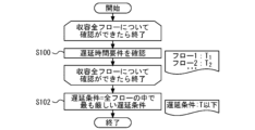
- FIG. 3 is a flowchart showing a process in which the AP determines a delay condition according to Embodiment 1 of the present disclosure.
- the delay time is determined from the delay time requirements inherent to each traffic flow.
- step 100 the AP checks the delay time requirements.
- the multilink transmission in question accommodates n traffic flows.
- delay time requirements are checked for all accommodated flows.
- step 102 the AP determines the delay conditions.
- the delay condition a case is shown in which the strictest delay time requirement of all flows is selected as the delay condition. This determines the delay conditions for the target multilink transmission.
- FIG. 4 is a flowchart showing a process for estimating the total delay time when the AP goes into link sleep according to Embodiment 1 of the present disclosure.
- the AP estimates the total delay time d n that would occur if a particular link were put to sleep.
- the total delay time d n is defined as the sum of the transmission time T n and the queuing time Q n .
- the transmission time T n is the channel use time of the own station, and is determined from MCS (Modulation and Coding Scheme) or the like.
- the queuing time Qn is the waiting time due to channel use by other stations, and is determined based on the degree of interference and the like. Furthermore, this prediction is performed for all combinations of all links included in the target multilink.
- One example of a method for predicting the total delay time d n is to add the transmission time T n of a link that has been put to sleep to the transmission time T n of a link that has not been put to sleep. For example, consider a case where link 8a in multilink 100 is put to sleep. In this case, the packet 6b flowing on the link 8a will be transmitted using the link 8b or link 8c. Therefore, the transmission time Tn of link 8a is added to the transmission time Tn of link 8b or link 8c. Thereby, the total delay time d n of link 8b and link 8c can be predicted.
- FIG. 5 is a flowchart illustrating a process for determining a link on which an AP sleeps, according to Embodiment 1 of the present disclosure.
- step 106 it is investigated whether the expected total delay time d n satisfies the delay condition. This investigation is performed on one combination of all links included in the target multilink. If the conditions are met, proceed to step 108. If the conditions are not met, proceed to step 110.
- step 108 the investigated combination of links is determined to be a combination that allows sleep, and is stored. Thereafter, the process returns to step 106 to investigate the next link combination.
- step 110 the investigated combination of links is determined to be a combination in which sleep is not possible and is stored. Thereafter, the process returns to step 106 to investigate the next link combination.
- step 112 the link combination with the largest number of links is selected from among the link combinations determined to be sleep-enabled combinations. Then, it is decided to put that combination of links to sleep.
- the first method is to select based on the total delay time d n . For example, by selecting a combination of links with the shortest total delay time d n , it is possible to perform multilink transmission that is most excellent in terms of total delay time. Note that depending on other requirements, it is also possible to select a combination of links in which the length of the total delay time d n is in an arbitrary order.
- the second method is to select based on transmission efficiency. For example, by selecting a combination of links with the best transmission efficiency, it is possible to perform multi-link transmission that is most excellent in terms of transmission efficiency. Note that depending on other requirements, it is also possible to select a combination of links that have an arbitrary ranking of transmission efficiency.
- the third method is to select based on the number of links to be used. For example, by selecting a combination of links that uses the least number of links, it is possible to put the maximum number of terminals to sleep, and therefore it is possible to perform multi-link transmission that is most excellent in terms of power consumption. Note that depending on other requirements, it is also possible to select a combination of links in which the number of links used is in an arbitrary order.
- the delay condition is 8 ms or less for flow 1.
- the transmission time of link 1, 2 ms is distributed to link 2 and link 3. That is, the total delay time of each link is as shown in Table 3. In this case, the total delay time for the entire multilink is the longest, 7 ms.
- multilink transmission is performed using all links and traffic flows. That is, three links and four traffic flows perform multi-link transmission using 12 transmitting and receiving circuits.
- link 1 is used to perform multilink transmission. That is, one link and four traffic flows perform multi-link transmission using four transmitting/receiving circuits.
- multi-link transmission can be performed using two-thirds of the transmitting and receiving circuits compared to the conventional example. As a result, reduction in power consumption and improvement in transmission efficiency can be achieved.
- FIG. 6 is a functional block diagram of the AP according to Embodiment 1 of the present disclosure.
- the AP 4 includes a wired NW connection function 16.
- the wired NW connection function 16 transmits the information transmitted from the MAC 3 to the transmission data distribution function 18.
- the transmission data distribution function 18 determines the link to sleep by performing the above-described predetermined processing. If AP4 is connected to a sleeping link, AP4 will be in a standby state. If the AP 4 is not connected to the sleep link, the transmission data distribution function 18 transmits the information transmitted from the MAC 3 to the access right acquisition function 20 .
- the access right acquisition function 20 implements CSMA/CA. If the access right can be obtained by CSMA/CA, the data transmission function 22 to the wireless medium performs wireless communication. As a result, multilink transmission is performed.
Landscapes
- Engineering & Computer Science (AREA)
- Computer Networks & Wireless Communication (AREA)
- Signal Processing (AREA)
- Mobile Radio Communication Systems (AREA)
Abstract
この開示は、無線通信装置及び無線通信方法に関する。この無線通信装置は、少なくとも一つのトラヒックフローを収容し、複数のリンクを用いてマルチリンク伝送を行う無線通信装置であって、以下の機能を含む。トラヒックフローの各々が有する遅延時間要件を比較し、遅延条件を決定する(機能1)。スリープさせるリンクの全ての組み合わせについて、合計遅延時間を予想する(機能2)。全ての組み合わせについて、遅延条件と合計遅延時間を比較し、スリープ可能なリンクの組み合わせか否かを判断する(機能3)。判断の結果から、スリープさせるリンクの組み合わせを選択する(機能4)。決定されたリンクの組み合わせに基づき、無線通信を行う(機能5)。
Description
本開示は、無線通信装置及び無線通信方法に関する。
無線LAN通信規格であるIEEE 802.11beでは、複数の周波数帯を併用できるマルチリンク伝送の機能が搭載されている。マルチリンク伝送では、異なるデータを複数の周波数帯で同時に伝送でき、これにより高速化を実現している。また、マルチリンク伝送で用いるリンクは、各々がCSMA/CAを実施している。
IEEE 802.11be標準化資料、IEEE 802.11-20/1935r64, "Compendium of straw polls and potential changes to the Specification Framework Document", "6 Multi-link operation" (https://mentor.ieee.org/802.11/dcn/20/11-20-1935-64-00be-compendium-of-straw-polls-and-potential-changes-to-the-specification-framework-document-part-2.docx)
しかし、複数のリンクでCSMA/CAを実施すると、常にキャリアセンス等を行う必要があるため、消費電力が増大する。特に、送信データが少ない場合、常に複数のリンクでCSMA/CAを実施すると、消費電力が増大するだけでなく、伝送効率も悪くなる。以上のように、マルチリンク伝送では、消費電力及び伝送効率の面で課題があった。
本開示は上述の問題を解決するため、データが少ない場合、またはデータ品質要件が満たされる場合は、一部のリンクを一定時間スリープさせる。これにより、消費電力の削減及び伝送効率の向上を達成できる無線通信装置及び無線通信方法を提供することを目的とする。
本開示の第一の態様は、少なくとも一つのトラヒックフローを収容し、複数のリンクを用いてマルチリンク伝送を行う無線通信装置であって、トラヒックフローの各々が有する遅延時間要件を比較し、遅延条件を決定する機能と、スリープさせるリンクの全ての組み合わせについて、合計遅延時間を予想する機能と、全ての組み合わせについて、遅延条件と合計遅延時間を比較し、スリープ可能なリンクの組み合わせか否かを判断する機能と、判断の結果から、スリープさせるリンクの組み合わせを選択する機能と、決定されたリンクの組み合わせに基づき、無線通信を行う機能を備える無線通信装置であることが好ましい。
本開示の第二の態様は、少なくとも一つのトラヒックフローを収容し、複数のリンクを用いてマルチリンク伝送を行う無線通信装置によって行われる無線通信方法であって、トラヒックフローの各々が有する遅延時間要件を比較し、遅延条件を決定する工程と、スリープさせるリンクの全ての組み合わせについて、合計遅延時間を予想する工程と、全ての組み合わせについて、遅延条件と合計遅延時間を比較し、スリープ可能なリンクの組み合わせか否かを判断する工程と、判断の結果から、スリープさせるリンクの組み合わせを決定する工程と、決定されたリンクの組み合わせに基づき、無線通信を行う工程を備える無線通信方法であることが好ましい。
本開示の第一及び第二の態様によれば、データが少ない場合、またはデータ品質要件が満たされる場合は、一部のリンクを一定時間スリープさせることで、消費電力の削減及び伝送効率の向上を達成できる。
実施の形態1
図1は、従来のマルチリンク伝送を示す図である。まず、マルチリンクで用いる一方のデバイスから、もう一方のデバイスへ情報伝達を行う場合の処理を説明する。
図1は、従来のマルチリンク伝送を示す図である。まず、マルチリンクで用いる一方のデバイスから、もう一方のデバイスへ情報伝達を行う場合の処理を説明する。
マルチリンク200は、MLD(Multi Link Device)2を備える。MLD2は、MAC(Multi Access Controller)3を有する。MAC3は、通信制御を行うコントローラであり、上位から伝達された情報をAP(Access Point)4a、4b及び4cへ伝達する。AP4aは、伝達された情報をパケット6aに変換し、リンク8aを介してMLD10へ伝達する。AP4bは、伝達された情報をパケット6bに変換し、リンク8bを介してMLD10へ伝達する。AP4cは、伝達された情報をパケット6cに変換し、リンク8cを介してMLD10へ伝達する。
MLD10は、パケット6a、6b及び6cを、STA12a、12b及び12cでそれぞれ受信する。STA12aは、パケット6aに含まれる情報をMAC14へ伝達する。STA12bは、パケット6bに含まれる情報をMAC14へ伝達する。STA12cは、パケット6cに含まれる情報をMAC14へ伝達する。MAC14は、受信した情報を上位に伝達する。
マルチリンク200でMLD2からMLD10へ情報伝達を行う場合、上述の処理を行う。MLD10からMLD2へ情報伝達を行う場合も、パケットの伝達方向が逆になるものの、同様の処理を行う。
上述の通り、マルチリンク伝送では、異なるデータを複数のリンクで双方向に伝送できる。すなわち、各リンクで異なる周波数帯を使用していれば、異なるデータを複数の周波数帯で同時に伝送できる。これにより、高速化を実現している。
しかし、従来のマルチリンク伝送では、消費電力及び伝送効率の面で課題がある。マルチリンク伝送で用いる複数のリンクは、各々がCSMA/CAを実施している。複数のリンクでCSMA/CAを実施すると、常にキャリアセンス等を行う必要があることから、消費電力が増大する。特に、送信データが少ない場合、常に複数のリンクでCSMA/CAを実施すると、消費電力が増大するだけでなく、伝送効率も悪くなる。本開示は、上述の課題を解決する。
図2は、本開示の実施の形態1に係るマルチリンク伝送を示す図である。本実施形態のマルチリンク伝送は、データが少ない場合、またはデータ品質要件が満たされる場合は、一部のリンクを一定時間スリープさせる。
実施の形態1に係るマルチリンク100は、MLD2を備える。MLD2は、MAC3を有する。MAC3は、上位から伝達された情報をAP4a、4b及び4cに伝達する。
AP4a、4b及び4cは、所定の処理を行うことで、使用するリンクを決定する。そして、決定されたリンクのみを用いてマルチリンク伝送を行う。所定の処理の内容については後述する。
図2では、リンク8aのみを用いて情報伝達を行う場合を示している。すなわち、AP4aが、伝達された情報をパケット6a、6b及び6cに変換し、リンク8aを介してMLD10へ伝達する。リンク8b及び8cは、スリープ状態となる。MLD10は、パケット6a、6b及び6cを、STA12aで受信する。STA12aは、パケット6a、6b及び6cに含まれる情報をMAC14へ伝達する。MAC14は、受信した情報を上位に伝達する。
図3は、本開示の実施の形態1に係る、APが遅延条件を決定する処理を示すフローである。遅延時間は、各トラヒックフローが固有に有する遅延時間要件から決定される。
まずステップ100で、APが遅延時間要件を確認する。対象となるマルチリンク伝送は、n通りのトラヒックフローを収容している。ステップ100では、収容している全フローについて、遅延時間要件を確認する。
次に、ステップ102でAPが遅延条件を決定する。ここでは、遅延条件として、全フローの遅延時間要件の中で最も厳しいものを選択する場合を示す。これにより、対象となるマルチリンク伝送での遅延条件が決定される。
図4は、本開示の実施の形態1に係る、APがリンクスリープ時の合計遅延時間を予想する処理を示すフローである。まずステップ104で、APが、特定のリンクをスリープさせた場合に生じる合計遅延時間dnを予想する。ここでは、合計遅延時間dnを、伝送時間Tnとキューイング時間Qnの和として定義する。伝送時間Tnは、自局のチャネル使用時間であり、MCS(Modulation and Coding Scheme)等から決定される。キューイング時間Qnは、他局のチャネル使用による待ち時間であり、干渉度合い等から決定される。また、この予想は、対象となるマルチリンクが有する全リンクの、全組み合わせについて実施する。
合計遅延時間dnの予想方法の一例として、スリープさせたリンクの伝送時間Tnを、スリープさせていないリンクの伝送時間Tnに上乗せする方法がある。例えば、マルチリンク100で、リンク8aをスリープさせる場合を考える。この場合、リンク8aに流れていたパケット6bは、リンク8bあるいはリンク8cを用いて伝送することとなる。そこで、リンク8aの伝送時間Tnを、リンク8bあるいはリンク8cの伝送時間Tnに上乗せする。これにより、リンク8b及びリンク8cの合計遅延時間dnを予想することができる。
図5は、本開示の実施の形態1に係る、APがスリープするリンクを決定する処理を示すフローである。まずステップ106で、予想される合計遅延時間dnが遅延条件を満たすかを調査する。この調査は、対象となるマルチリンクが有する全リンクの、組み合わせの一つについて行う。条件を満たす場合、ステップ108に進む。条件を満たさない場合、ステップ110に進む。
ステップ108では、調査したリンクの組み合わせについて、スリープ可能な組み合わせであると判断し、記憶する。その後、次のリンクの組み合わせについて調査するため、ステップ106に戻る。
ステップ110では、調査したリンクの組み合わせについて、スリープ不可能な組み合わせであると判断し、記憶する。その後、次のリンクの組み合わせについて調査するため、ステップ106に戻る。
上述のステップ106、108、110で行う調査は、対象となるマルチリンクが有する全リンクの、全組み合わせについて実施する。調査が完了したら、ステップ112へ進む。
ステップ112では、スリープ可能な組み合わせと判断したリンクの組み合わせの中から、リンク数が最も多いリンクの組み合わせを選択する。そして、そのリンクの組み合わせについて、スリープさせることを決定する。
候補となるリンクの組み合わせが複数ある場合の選択方法としては、3通りの方法が例示できる。1つ目の方法は、合計遅延時間dnに基づいて選択する方法である。例えば、合計遅延時間dnが最も短いリンクの組み合わせを選択することで、合計遅延時間の観点で最も優れたマルチリンク伝送を行うことができる。なお、その他の要件によっては、合計遅延時間dnの長さが任意の順位となるリンクの組み合わせを選択することも可能である。
2つ目の方法は、伝送効率に基づいて選択する方法である。例えば、伝送効率が最も良いリンクの組み合わせを選択することで、伝送効率の観点で最も優れたマルチリンク伝送を行うことができる。なお、その他の要件によっては、伝送効率の良さが任意の順位となるリンクの組み合わせを選択することも可能である。
3つ目の方法は、使用するリンクの数に基づいて選択する方法である。例えば、最も少ないリンクを用いるリンクの組み合わせを選択することで、最も多くの端末をスリープさせることができるため、消費電力の観点で最も優れたマルチリンク伝送を行うことができる。なお、その他の要件によっては、使用するリンクの数が任意の順位となるリンクの組み合わせを選択することも可能である。
これ以降、本実施形態において、スリープするリンクを決定する処理の具体例を示す。ここでは、リンク数が3であり、トラヒックフロー数が4であるマルチリンク伝送について考える。各リンクの合計遅延時間dnは、表1の通りとする。

また、各トラヒックフローの遅延時間要件は表2の通りとする。

まず、遅延条件を決定する。ここでは、4つのフローが有する遅延時間要件を比較し、最も厳しいものを遅延条件とする。すなわち、フロー1の8ms以下が遅延条件となる。
続けて、リンクスリープ時の合計遅延時間を予想する。ここでは、3つのリンクの全組み合わせについて、合計遅延時間を予想する。
例えば、リンク1をスリープさせる場合、リンク1の伝送時間である2msを、リンク2及びリンク3に分配する。すなわち、各リンクの合計遅延時間は表3の通りとなる。この場合、マルチリンク全体での合計遅延時間は、最も長い7msとなる。

同様の手順で、全リンクの全組み合わせについて、合計遅延時間を予想する。さらに、予想した合計遅延時間を、遅延条件と比較し、スリープ可能なリンクの組み合わせであるかを判断する。予想される合計遅延時間と、スリープ可能なリンクの組み合わせであるかの判断結果は、ここでは表4の通りとなる。

表4より、スリープ可能なリンクの組み合わせは4通りである。ここでは、消費電力を低減させるため、最も少ないリンクを用いるリンクの組み合わせを選択することとする。その場合、リンク2及び3をスリープさせる組み合わせ、すなわちリンク1のみを用いてマルチリンク伝送を行うことを選択する。
従来例では、全てのリンク及びトラヒックフローを用いてマルチリンク伝送を行う。すなわち、3つのリンクと4つのトラヒックフローにより、12の送受信回路を用いたマルチリンク伝送を行う。一方本実施形態では、上述の通り、リンク1のみを用いてマルチリンク伝送を行う。すなわち、1つのリンクと4つのトラヒックフローにより、4の送受信回路を用いたマルチリンク伝送を行う。これにより、従来例と比較して、2/3の送受信回路でマルチリンク伝送を行うことができる。その結果、消費電力の低減及び伝送効率の向上が達成できる。
図6は、本開示の実施の形態1に係るAPの機能ブロック図である。AP4は、有線NW接続機能16を備える。有線NW接続機能16は、MAC3から伝達された情報を、送信データ振り分け機能18へ伝達する。
送信データ振り分け機能18は、前述した所定の処理を行うことで、スリープするリンクを決定する。AP4がスリープするリンクと接続されている場合、AP4は待機状態となる。AP4がスリープするリンクと接続されていない場合、送信データ振り分け機能18は、MAC3から伝達された情報を、アクセス権取得機能20へ伝達する。
アクセス権取得機能20は、CSMA/CAを実施する。CSMA/CAによってアクセス権が取得できた場合、無線媒体へのデータ送信機能22が、無線通信を実施する。これにより、マルチリンク伝送が行われる。
1 フロー
8a リンク
8b リンク
8c リンク
100 マルチリンク
200 マルチリンク
8a リンク
8b リンク
8c リンク
100 マルチリンク
200 マルチリンク
Claims (8)
- 少なくとも一つのトラヒックフローを収容し、複数のリンクを用いてマルチリンク伝送を行う無線通信装置であって、
前記トラヒックフローの各々が有する遅延時間要件を比較し、遅延条件を決定する機能と、
スリープさせるリンクの全ての組み合わせについて、合計遅延時間を予想する機能と、
前記全ての組み合わせについて、前記遅延条件と前記合計遅延時間を比較し、スリープ可能なリンクの組み合わせか否かを判断する機能と、
前記判断の結果から、スリープさせるリンクの組み合わせを選択する機能と、
決定されたリンクの組み合わせに基づき、無線通信を行う機能
を備える無線通信装置。 - 前記遅延条件が、前記遅延時間要件の中で最も厳しいものに決定される
請求項1に記載の無線通信装置。 - 前記合計遅延時間が、自局のチャネル使用時間である伝送時間と、他局のチャネル使用による待ち時間であるキューイング時間から決定される
請求項1または2に記載の無線通信装置。 - 前記合計遅延時間の予想が、スリープさせたリンクの前記伝送時間を、スリープさせていないリンクの前記伝送時間に上乗せすることで行われる
請求項3に記載の無線通信装置。 - 前記選択が、合計遅延時間に基づいて行われる、請求項1に記載の無線通信装置。
- 前記選択が、伝送効率に基づいて行われる、請求項1に記載の無線通信装置。
- 前記選択が、使用するリンクの数に基づいて行われる、請求項1に記載の無線通信装置。
- 少なくとも一つのトラヒックフローを収容し、複数のリンクを用いてマルチリンク伝送を行う無線通信装置によって行われる無線通信方法であって、
前記トラヒックフローの各々が有する遅延時間要件を比較し、遅延条件を決定する工程と、
スリープさせるリンクの全ての組み合わせについて、合計遅延時間を予想する工程と、
前記全ての組み合わせについて、前記遅延条件と前記合計遅延時間を比較し、スリープ可能なリンクの組み合わせか否かを判断する工程と、
前記判断の結果から、スリープさせるリンクの組み合わせを決定する工程と、
決定されたリンクの組み合わせに基づき、無線通信を行う工程
を備える無線通信方法。
Priority Applications (1)
| Application Number | Priority Date | Filing Date | Title |
|---|---|---|---|
| PCT/JP2022/023661 WO2023242915A1 (ja) | 2022-06-13 | 2022-06-13 | 無線通信装置及び無線通信方法 |
Applications Claiming Priority (1)
| Application Number | Priority Date | Filing Date | Title |
|---|---|---|---|
| PCT/JP2022/023661 WO2023242915A1 (ja) | 2022-06-13 | 2022-06-13 | 無線通信装置及び無線通信方法 |
Publications (1)
| Publication Number | Publication Date |
|---|---|
| WO2023242915A1 true WO2023242915A1 (ja) | 2023-12-21 |
Family
ID=89192604
Family Applications (1)
| Application Number | Title | Priority Date | Filing Date |
|---|---|---|---|
| PCT/JP2022/023661 WO2023242915A1 (ja) | 2022-06-13 | 2022-06-13 | 無線通信装置及び無線通信方法 |
Country Status (1)
| Country | Link |
|---|---|
| WO (1) | WO2023242915A1 (ja) |
Citations (1)
| Publication number | Priority date | Publication date | Assignee | Title |
|---|---|---|---|---|
| JP2011146784A (ja) * | 2010-01-12 | 2011-07-28 | Nippon Telegr & Teleph Corp <Ntt> | 光加入者線終端装置 |
-
2022
- 2022-06-13 WO PCT/JP2022/023661 patent/WO2023242915A1/ja unknown
Patent Citations (1)
| Publication number | Priority date | Publication date | Assignee | Title |
|---|---|---|---|---|
| JP2011146784A (ja) * | 2010-01-12 | 2011-07-28 | Nippon Telegr & Teleph Corp <Ntt> | 光加入者線終端装置 |
Non-Patent Citations (1)
| Title |
|---|
| RONNY YONGHO KIM (KNUT): "Issues on MLD Power Saving", IEEE DRAFT; 11-20-1402-01-00BE-ISSUES-ON-MLD-POWER-SAVING, IEEE-SA MENTOR, PISCATAWAY, NJ USA, vol. 802.11 EHT; 802.11be, no. 1, 28 October 2020 (2020-10-28), Piscataway, NJ USA , pages 1 - 13, XP068174070 * |
Similar Documents
| Publication | Publication Date | Title |
|---|---|---|
| US11889557B2 (en) | Wireless communication system, wireless communication method, wireless LAN access point, and wireless LAN station | |
| US7738374B2 (en) | Channel allocation for access point in mesh network | |
| RU2391798C2 (ru) | Использование сообщений использования ресурсов в мас с множеством несущих для достижения равноправности | |
| Wen et al. | QoS-aware mode selection and resource allocation scheme for device-to-device (D2D) communication in cellular networks | |
| Singh et al. | Optimal traffic aggregation in multi-RAT heterogeneous wireless networks | |
| US20090059877A1 (en) | Wireless communication device and method for controlling wireless communication device | |
| US7899459B2 (en) | Call admission control device and call admission control method | |
| US10264592B2 (en) | Method and radio network node for scheduling of wireless devices in a cellular network | |
| MX2010011771A (es) | Metodo y aparato para reutilizacion de frecuencia en un sistema de comunicaciones de multi-portadora. | |
| JP2008118656A (ja) | セルラー通信システムにおける上りリンク資源のスケジューリング方法 | |
| US20120033570A1 (en) | Downlink inter-cell interference coordination method and enb | |
| EP2445276A2 (en) | Method for cooperative control of power among base stations and base station device using same | |
| Ko et al. | Joint optimization of channel selection and frame scheduling for coexistence of LTE and WLAN | |
| WO2012174916A1 (zh) | 异系统间频谱共享情况下的干扰抑制方法和设备 | |
| Vučević et al. | Reinforcement learning for joint radio resource management in LTE-UMTS scenarios | |
| Song et al. | Adaptive and distributed radio resource allocation in densely deployed wireless LANs: A game-theoretic approach | |
| US20120063404A1 (en) | Method and Apparatus | |
| Elgendi et al. | Traffic offloading for 5G: L-LTE or Wi-Fi | |
| WO2023242915A1 (ja) | 無線通信装置及び無線通信方法 | |
| Merlhe et al. | Hybrid joint-transmission multi-point coordination for inter-cell interference management | |
| RU2364043C2 (ru) | Согласованное автономное и запланированное выделение ресурсов в распределенной системе связи | |
| WO2023242918A1 (ja) | 無線通信システム、無線通信方法及び無線通信装置 | |
| Ge et al. | Access point selection for WLANs with cognitive radio: A restless bandit approach | |
| Ruan et al. | Efficient traffic scheduling for coexistence of eMBB and uRLLC in industrial IoT networks | |
| Zeinali et al. | AI-based Radio Resource and Transmission Opportunity Allocation for 5G-V2X HetNets: NR and NR-U networks |
Legal Events
| Date | Code | Title | Description |
|---|---|---|---|
| 121 | Ep: the epo has been informed by wipo that ep was designated in this application |
Ref document number: 22946735 Country of ref document: EP Kind code of ref document: A1 |