WO2023242886A1 - 顔向き推定装置、脇見判断システム、及び顔向き推定方法 - Google Patents
顔向き推定装置、脇見判断システム、及び顔向き推定方法 Download PDFInfo
- Publication number
- WO2023242886A1 WO2023242886A1 PCT/JP2022/023559 JP2022023559W WO2023242886A1 WO 2023242886 A1 WO2023242886 A1 WO 2023242886A1 JP 2022023559 W JP2022023559 W JP 2022023559W WO 2023242886 A1 WO2023242886 A1 WO 2023242886A1
- Authority
- WO
- WIPO (PCT)
- Prior art keywords
- occupant
- unit
- nose
- calculation unit
- calculates
- Prior art date
- Legal status (The legal status is an assumption and is not a legal conclusion. Google has not performed a legal analysis and makes no representation as to the accuracy of the status listed.)
- Ceased
Links
Images




Classifications
-
- B—PERFORMING OPERATIONS; TRANSPORTING
- B60—VEHICLES IN GENERAL
- B60W—CONJOINT CONTROL OF VEHICLE SUB-UNITS OF DIFFERENT TYPE OR DIFFERENT FUNCTION; CONTROL SYSTEMS SPECIALLY ADAPTED FOR HYBRID VEHICLES; ROAD VEHICLE DRIVE CONTROL SYSTEMS FOR PURPOSES NOT RELATED TO THE CONTROL OF A PARTICULAR SUB-UNIT
- B60W40/00—Estimation or calculation of non-directly measurable driving parameters for road vehicle drive control systems not related to the control of a particular sub unit, e.g. by using mathematical models
- B60W40/08—Estimation or calculation of non-directly measurable driving parameters for road vehicle drive control systems not related to the control of a particular sub unit, e.g. by using mathematical models related to drivers or passengers
-
- G—PHYSICS
- G08—SIGNALLING
- G08G—TRAFFIC CONTROL SYSTEMS
- G08G1/00—Traffic control systems for road vehicles
- G08G1/16—Anti-collision systems
Definitions
- the present disclosure relates to a face orientation estimation device, an inattentiveness determination system, and a face orientation estimation method.
- the driver monitoring device described in Patent Document 1 which is common to the face direction estimation device according to the present disclosure in that it detects the face direction of the driver of a vehicle, detects the direction of the driver's face, for example, by detecting the direction of the driver's left and right eyes. Detection is performed using the ratio of the distance between the line connecting the line and the distance between the line connecting the nose tip and the intersection of a perpendicular line drawn from the tip of the driver's nose to the line.
- a face orientation estimation device includes a photographing unit that photographs an image of an occupant in a vehicle, and a first distance between the occupant's eyes based on the image of the occupant.
- a photographing unit that photographs an image of an occupant in a vehicle
- a first distance between the occupant's eyes based on the image of the occupant.
- a second calculation unit that calculates a second distance between the inferred position of the passenger's nose and the midpoint between the passenger's eyes; , a third calculation unit that calculates the ratio between the first distance calculated by the first calculation unit and the second distance calculated by the second calculation unit; It includes a comparison section that compares the ratio with a predetermined reference value, and an estimation section that estimates whether the position of the occupant's nose inferred by the inference section is correct based on the comparison result by the comparison section.
- the face orientation estimation device it is possible to estimate whether the inferred position of the nose of the occupant in the vehicle, which is difficult to visually recognize, is appropriate.
- FIG. 2 is a functional block diagram of a face orientation estimation device KS according to the first embodiment.
- the first distance KR1, the second distance KR2, and the ratio HI of the occupant JI in the first embodiment are shown.
- FIG. 3A shows the black three-dimensional mask MA (original position) of occupant JI in the first embodiment.
- FIG. 3B shows the black three-dimensional mask MA (shifted position) of occupant JI in the first embodiment.
- 1 shows a hardware configuration of a face orientation estimation device KS according to the first embodiment.
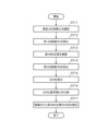
- 3 is a flowchart showing the operation of the face orientation estimation device KS of the first embodiment. An image GZ of a modification of the first embodiment is shown.
- FIG. 3 is a functional block diagram of a face orientation estimation device KS according to a second embodiment.
- the face direction KM and the face direction angle KK of the passenger JI in Embodiment 2 are shown.
- 7 is a flowchart showing the operation of the face orientation estimation device KS of the second embodiment.
- the configuration of the inattentiveness determination system WH of Embodiment 3 is shown.
- Embodiment 1 The face direction estimation device KS of Embodiment 1 will be described.
- FIG. 1 is a functional block diagram of the face orientation estimation device KS of the first embodiment.
- FIG. 2 shows the first distance KR1, the second distance KR2, and the ratio HI of the occupant JI in the first embodiment.
- FIG. 3 shows the black three-dimensional mask MA of the passenger JI of Embodiment 1.
- the face orientation estimation device KS of the first embodiment includes an imaging section SE, a first calculation section SS1, an inference section SR, a second calculation section SS2, and a third calculation section. It includes SS3, a comparison section HK, and an estimation section ST.
- the face orientation estimation device KS also includes a learned model GM and a reference value KJ, as shown in FIG.
- the photographing section SE corresponds to the "photographing section”
- the first calculation section SS1 corresponds to the “first calculation section”
- the reasoning section SR corresponds to the "reasoning section”
- the second calculation section SS1 corresponds to the "first calculation section”.
- SS2 corresponds to the "second calculation section”
- the third calculation section SS3 corresponds to the "third calculation section”
- the comparison section HK corresponds to the "comparison section”
- the estimation section ST corresponds to the "comparison section”.
- the photographing unit SE photographs an image GZ (shown in FIG. 1) of a passenger JI (for example, shown in FIG. 1) riding in a vehicle SY (not shown) such as a car. More specifically, the imaging unit SE is wearing, for example, a black three-dimensional mask MA (shown in FIGS. 3A and 3B), and it is difficult to visually recognize the position of the nose HN (shown in FIG. 2). Capture image GZ of crew member JI. For example, the photographing unit SE captures an image GZ of the passenger JI with the black 3D mask MA in its original position (as shown in FIG. 3A), and an image GZ of the passenger JI with the black 3D mask MA in a position shifted downward (as shown in FIG. 3B).
- the position of the nasal HN refers to, for example, the overall position of the nasal HN, and the partial position of the nasal HN (for example, the position of the nasal tip of the nasal HN, the position of the nasal bridge of the nasal HN, the nasal root of the nasal HN). position of the nasal alar of the nasal HN).
- the first calculation unit SS1 calculates a first distance KR1 (shown in FIGS. 1 and 2), which is the distance between the eyes of the passenger JI, based on the image GZ of the passenger JI.
- the inference unit SR infers the position of the occupant JI's nose HN in the photographed image GZ by referring to the learned model GM.
- the learned model GM has a predetermined relationship between multiple images of people whose nose positions are difficult to visually recognize and the position of the nose of said person, regardless of whether or not crew member JI is included. being learned.
- the second calculation unit SS2 calculates a second distance KR2 (Figs. 1, 2 ) is calculated.
- the third calculation unit SS3 calculates a ratio HI between the first distance KR1 calculated by the first calculation unit SS1 and the second distance KR2 calculated by the second calculation unit SS2 (FIGS. 1 and 2). ) is calculated.
- the comparison unit HK compares the ratio HI calculated by the third calculation unit SS3 with the reference value KJ.
- the reference value KJ is, for example, a predetermined value obtained by analyzing a plurality of ratios HI for the plurality of people described above.
- the estimation unit ST determines whether or not the position of the nose HN of the occupant JI inferred by the inference unit SR is valid, based on the above-described comparison result by the comparison unit HK, that is, whether or not the inferred position of the nose HN is valid. Estimate.
- FIG. 4 shows the hardware configuration of the face direction estimation device KS of the first embodiment.
- the input section N and the output section S include, for example, an input interface and an output interface for exchanging input signals NS and output signals SS related to the operation of the processor P with the outside of the face orientation estimation device KS. be done.
- the processor P executes the program PR stored in the storage medium K using the memory M, and also executes the program PR as necessary.
- the input section N, and the output section S, the functions of each section from the photographing section SE to the estimating section ST are realized.
- FIG. 5 is a flowchart showing the operation of the face direction estimation device KS of the first embodiment.
- the operation of the face direction estimation device KS of the first embodiment will be explained with reference to the flowchart of FIG. 5.
- Step ST13 The inference unit SR (shown in FIG. 1) infers the position of the passenger JI's nose HN by referring to the learned model GM (shown in FIG. 1) based on the image GZ of the passenger JI. .
- Step ST14 The second calculation unit SS2 (shown in FIG. 1) calculates a second distance, which is the distance between the position of the nose HN inferred by the inference unit SR and the midpoint between the eyes of the occupant JI. KR2 (shown in FIGS. 1 and 2) is calculated.
- Step ST15 The second calculation unit SS2 (shown in FIG. 1) calculates the first distance KR1 (shown in FIGS. 1 and 2) calculated by the first calculation unit SS1 and the second calculation unit SS2.
- the ratio HI shown in FIGS. 1 and 2) to the second distance KR2 (shown in FIGS. 1 and 2) calculated by is calculated.
- Step ST16 The comparison unit HK (shown in FIG. 1) compares the ratio HI calculated by the third calculation unit SS3 and the reference value KJ (shown in FIG. 1).
- Step ST17 The estimation unit ST (shown in FIG. 1) estimates whether or not the position of the passenger JI's nose HN inferred by the inference unit SR is appropriate based on the comparison result by the comparison unit HK. .
- the third calculation unit SS3 calculates a plurality of images GZ of the occupant JI of the vehicle SY taken by the imaging unit SE, for example, a predetermined number n (n is For each image GZ of images GZ(1), GZ(2), GZ(3), .
- the third calculation unit SS3 calculates the ratio HI of each of the n images GZ, that is, the average value of the n ratios HI by averaging the n ratios HI. Good too.
- the estimating unit ST calculates the value of the occupant JI inferred by the inferring unit SR, which may occur, for example, when the occupant JI temporarily looks aside or temporarily looks down. It becomes possible to reduce the negative influence on the estimation by the estimation unit ST due to a large change in the position of the nose HN.
- Embodiment 2 A face direction estimation device KS according to a second embodiment will be described.
- FIG. 7 is a functional block diagram of the face orientation estimation device KS according to the second embodiment.
- the face direction estimation device KS of Embodiment 2 estimates that the face direction of the passenger JI is as if he is looking down, due to the fact that the black three-dimensional mask MA is in a shifted position (as shown in FIG. 3B). (Illustrated in FIG. 8B), and as a result, the objective is to suppress erroneous judgment that the nose HN of the occupant JI is at a lower position than its original position.
- the face orientation estimation device KS of the second embodiment differs from the face orientation estimation device KS of the first embodiment in that it further includes a fourth calculation unit SS4 and a correction unit HS. include.
- the fourth calculation unit SS4 corresponds to a “fourth calculation unit”, and the “correction unit HS” corresponds to a “correction unit”.
- the fourth calculation unit SS4 calculates the face direction angle KK of the occupant JI (hereinafter referred to as "face direction angle KK") based on the ratio HI (shown in FIGS. 2 and 7) and the reference value KJ (shown in FIG. 7). ), for example, the black 3D mask MA is in a shifted position (as shown in FIG. 3B) with respect to the horizontal direction SU, so that the face of the passenger JI appears to be tilted downward. A certain angle (illustrated in FIG. 8B), the so-called pitch angle, is calculated.
- the fourth calculation unit SS4 calculates that when the ratio HI is slightly smaller than the reference value KJ, in other words, when the second distance KR2 is photographed as if it were slightly smaller, for example, the face of the passenger JI is The angle that appears to be pointing slightly downward is calculated to be ⁇ (not shown).
- the correction unit HS adjusts the fourth correction unit according to the degree to which the position of the nose HN of the occupant JI is inappropriate.
- the face direction angle KK of the passenger JI calculated by the calculation unit SS4 is corrected. More specifically, the correction unit HS corrects the face orientation KM of the occupant JI (illustrated in FIG. 8B) caused by the shifted position of the black three-dimensional mask MA from the original facial orientation KM of the occupant JI (illustrated in FIG. 8A). ), the larger the extent to which the position of the nose HN of the occupant JI is inappropriate, the larger the correction is made to the face orientation angle KK of the occupant JI.
- FIG. 9 is a flowchart showing the operation of the face orientation estimation device KS of the second embodiment.
- the operation of the face direction estimation device KS of the second embodiment will be explained with reference to the flowchart of FIG. 9.
- Step ST26 The comparison unit HK (shown in FIG. 7) compares the ratio HI and the reference value KJ. As shown in FIG. 9, when the ratio HI is not smaller than the reference value KJ, that is, when the position of the passenger JI's nose HN inferred by the inference unit SR is appropriate (“NO”), the process is performed. , proceed to step ST27. On the other hand, when the ratio HI is smaller than the reference value KJ, that is, when the position of the occupant JI's nose HN inferred by the inference unit SR is not valid (“YES”), the process proceeds to step ST28.
- Step ST27 For example, the estimation unit ST (shown in FIG. 1) directly outputs the position of the passenger JI's nose HN inferred by the inference unit SR.
- Step ST28 The fourth calculation unit SS4 (shown in FIG. 7) calculates the face orientation angle KK of the occupant JI based on the ratio HI (shown in FIG. 2) and the reference value KJ.
- Step ST29 The correction unit HS (shown in FIG. 7) calculates the position of the occupant JI calculated by the fourth calculation unit SS4 as The face orientation angle KK of the passenger JI due to the shifted position of the black 3D mask MA (shown in FIG. 8B) is the original face orientation KM of the passenger JI (shown in FIG. 8A). Make larger corrections to get closer to .
- Step ST30 The correction unit HS outputs the corrected face orientation angle KK of the occupant JI, that is, the corrected position of the nose HN of the occupant JI.
- Embodiment 3 An inattentiveness determination system according to a third embodiment will be described.
- FIG. 10 shows the configuration of the inattentiveness determination system WH of the third embodiment.
- the inattentiveness determination system WH of the third embodiment includes the face direction estimation device KS of the first or second embodiment, the inattentiveness detection device WKS, and the inattentiveness warning device WKH.
- the face orientation estimation device KS infers the position of the nose HN of the occupant JI and corrects it as necessary, and the inattentiveness detection device WKS infers the position of the nose HN of the occupant JI.
- the inattentiveness warning device WKH detects whether or not the occupant JI is inattentive, and the inattentiveness warning device WKH issues an alarm (for example, display For example, the passenger JI is notified by the warning sound and warning sound). Thereby, the occupant JI can be encouraged to concentrate on driving the vehicle SY in which the occupant JI is riding.
- a face orientation estimation device KS having a photographing unit SE that photographs only the driver of the vehicle SY, when it is difficult to visually recognize the position of the driver's nose HN, multiple images of the driver are photographed.
- GZ is the target image in the embodiment.
- a face orientation estimation device KS having an imaging unit SE that captures images including the driver and fellow passengers in the imaging range, such as the entire interior of the vehicle SY, it is difficult to visually recognize the position of the nose HN of a person within the vehicle SY.
- a plurality of images in which crew member A is photographed are images targeted for the embodiment.
- a face orientation estimation device KS having an imaging unit SE that captures images including the driver and fellow passengers in the imaging range, such as the entire interior of the vehicle SY
- each of the plurality of images in which occupant A is photographed and the plurality of images in which occupant B is photographed is a target image of the embodiment.
- the face orientation estimation device can be used to estimate whether the inferred position of the nose of an occupant in a vehicle, which is difficult to visually recognize, is appropriate.
- GM trained model GZ image, HI ratio, HK comparison section, HN nose, JI passenger, KJ reference value, KK face direction angle, KM face direction, KR1 first distance, KR2 second distance, KS face direction estimation Apparatus, MA black 3D mask, SE imaging unit, SR inference unit, SS1 first calculation unit, SS2 second calculation unit, SS3 third calculation unit, SS4 fourth calculation unit, ST estimation unit.
Landscapes
- Engineering & Computer Science (AREA)
- Physics & Mathematics (AREA)
- General Physics & Mathematics (AREA)
- Automation & Control Theory (AREA)
- Mathematical Physics (AREA)
- Transportation (AREA)
- Mechanical Engineering (AREA)
- Control Of Driving Devices And Active Controlling Of Vehicle (AREA)
- Traffic Control Systems (AREA)
- Image Analysis (AREA)
- Image Processing (AREA)
Priority Applications (2)
| Application Number | Priority Date | Filing Date | Title |
|---|---|---|---|
| JP2024527895A JP7523726B2 (ja) | 2022-06-13 | 2022-06-13 | 顔向き推定装置、脇見判断システム、及び顔向き推定方法 |
| PCT/JP2022/023559 WO2023242886A1 (ja) | 2022-06-13 | 2022-06-13 | 顔向き推定装置、脇見判断システム、及び顔向き推定方法 |
Applications Claiming Priority (1)
| Application Number | Priority Date | Filing Date | Title |
|---|---|---|---|
| PCT/JP2022/023559 WO2023242886A1 (ja) | 2022-06-13 | 2022-06-13 | 顔向き推定装置、脇見判断システム、及び顔向き推定方法 |
Publications (1)
| Publication Number | Publication Date |
|---|---|
| WO2023242886A1 true WO2023242886A1 (ja) | 2023-12-21 |
Family
ID=89192475
Family Applications (1)
| Application Number | Title | Priority Date | Filing Date |
|---|---|---|---|
| PCT/JP2022/023559 Ceased WO2023242886A1 (ja) | 2022-06-13 | 2022-06-13 | 顔向き推定装置、脇見判断システム、及び顔向き推定方法 |
Country Status (2)
| Country | Link |
|---|---|
| JP (1) | JP7523726B2 (https=) |
| WO (1) | WO2023242886A1 (https=) |
Citations (3)
| Publication number | Priority date | Publication date | Assignee | Title |
|---|---|---|---|---|
| JP2010157073A (ja) * | 2008-12-26 | 2010-07-15 | Fujitsu Ltd | 顔認識装置、顔認識方法及び顔認識プログラム |
| WO2021156914A1 (ja) * | 2020-02-03 | 2021-08-12 | 三菱電機株式会社 | 注意方向判定装置および注意方向判定方法 |
| JP2021193624A (ja) * | 2019-11-22 | 2021-12-23 | パイオニア株式会社 | 認識装置、認識方法及び認識プログラム |
-
2022
- 2022-06-13 WO PCT/JP2022/023559 patent/WO2023242886A1/ja not_active Ceased
- 2022-06-13 JP JP2024527895A patent/JP7523726B2/ja active Active
Patent Citations (3)
| Publication number | Priority date | Publication date | Assignee | Title |
|---|---|---|---|---|
| JP2010157073A (ja) * | 2008-12-26 | 2010-07-15 | Fujitsu Ltd | 顔認識装置、顔認識方法及び顔認識プログラム |
| JP2021193624A (ja) * | 2019-11-22 | 2021-12-23 | パイオニア株式会社 | 認識装置、認識方法及び認識プログラム |
| WO2021156914A1 (ja) * | 2020-02-03 | 2021-08-12 | 三菱電機株式会社 | 注意方向判定装置および注意方向判定方法 |
Also Published As
| Publication number | Publication date |
|---|---|
| JPWO2023242886A1 (https=) | 2023-12-21 |
| JP7523726B2 (ja) | 2024-07-26 |
Similar Documents
| Publication | Publication Date | Title |
|---|---|---|
| JP5127583B2 (ja) | 対象物判定装置及びプログラム | |
| JP4728432B2 (ja) | 顔姿勢推定装置、顔姿勢推定方法、及び、顔姿勢推定プログラム | |
| CN104573623B (zh) | 人脸检测装置、方法 | |
| JP6573193B2 (ja) | 判定装置、判定方法、および判定プログラム | |
| WO2017208529A1 (ja) | 運転者状態推定装置、運転者状態推定システム、運転者状態推定方法、運転者状態推定プログラム、対象者状態推定装置、対象者状態推定方法、対象者状態推定プログラム、および記録媒体 | |
| CN107527000A (zh) | 利用眼睛跟踪来监视驾驶员的集中度的装置和方法 | |
| US20210370956A1 (en) | Apparatus and method for determining state | |
| CN118097628A (zh) | 一种面向遮挡脸部的驾驶员疲劳检测方法及装置 | |
| JP4173083B2 (ja) | 覚醒状態判定装置及び覚醒状態判定方法 | |
| CN111784759A (zh) | 基于计算机视觉的船舶高度计算方法、系统和存储介质 | |
| CN110192224A (zh) | 驾驶员状态推断装置以及驾驶员状态推断方法 | |
| WO2023242886A1 (ja) | 顔向き推定装置、脇見判断システム、及び顔向き推定方法 | |
| JP2010003116A (ja) | 対象物判定装置及びプログラム | |
| JP7384158B2 (ja) | 画像処理装置、移動装置、および方法、並びにプログラム | |
| JP5004923B2 (ja) | 車両の運転支援装置 | |
| WO2021199124A1 (ja) | 検出装置 | |
| WO2022135589A1 (zh) | 安全带佩戴检测方法、装置、存储介质及处理器 | |
| US11587336B2 (en) | Gaze target detector | |
| US12594953B2 (en) | Driver monitor, method, and computer program for monitoring driver | |
| JP2001043377A (ja) | フェールセーフ機能を有する車外監視装置 | |
| KR102906380B1 (ko) | 운전자의 뇌졸증 전조증상을 검출하기 위한 장치 및 방법 | |
| JP2022012829A (ja) | ドライバモニタ装置及びドライバモニタ方法 | |
| JP2024061803A (ja) | 判定装置 | |
| JP2002190027A (ja) | 画像認識による速度測定システム及び速度測定方法 | |
| JP7770574B2 (ja) | 体調異常検出装置及び体調異常検出方法 |
Legal Events
| Date | Code | Title | Description |
|---|---|---|---|
| 121 | Ep: the epo has been informed by wipo that ep was designated in this application |
Ref document number: 22946706 Country of ref document: EP Kind code of ref document: A1 |
|
| ENP | Entry into the national phase |
Ref document number: 2024527895 Country of ref document: JP Kind code of ref document: A |
|
| NENP | Non-entry into the national phase |
Ref country code: DE |
|
| 122 | Ep: pct application non-entry in european phase |
Ref document number: 22946706 Country of ref document: EP Kind code of ref document: A1 |