WO2023238545A1 - 原水処理方法及び原水処理装置 - Google Patents
原水処理方法及び原水処理装置 Download PDFInfo
- Publication number
- WO2023238545A1 WO2023238545A1 PCT/JP2023/016543 JP2023016543W WO2023238545A1 WO 2023238545 A1 WO2023238545 A1 WO 2023238545A1 JP 2023016543 W JP2023016543 W JP 2023016543W WO 2023238545 A1 WO2023238545 A1 WO 2023238545A1
- Authority
- WO
- WIPO (PCT)
- Prior art keywords
- treatment tank
- raw water
- activated sludge
- treated
- concentration
- Prior art date
- Legal status (The legal status is an assumption and is not a legal conclusion. Google has not performed a legal analysis and makes no representation as to the accuracy of the status listed.)
- Ceased
Links
Images
Classifications
-
- C—CHEMISTRY; METALLURGY
- C02—TREATMENT OF WATER, WASTE WATER, SEWAGE, OR SLUDGE
- C02F—TREATMENT OF WATER, WASTE WATER, SEWAGE, OR SLUDGE
- C02F3/00—Biological treatment of water, waste water, or sewage
- C02F3/02—Aerobic processes
- C02F3/12—Activated sludge processes
-
- C—CHEMISTRY; METALLURGY
- C02—TREATMENT OF WATER, WASTE WATER, SEWAGE, OR SLUDGE
- C02F—TREATMENT OF WATER, WASTE WATER, SEWAGE, OR SLUDGE
- C02F1/00—Treatment of water, waste water, or sewage
- C02F1/44—Treatment of water, waste water, or sewage by dialysis, osmosis or reverse osmosis
-
- C—CHEMISTRY; METALLURGY
- C02—TREATMENT OF WATER, WASTE WATER, SEWAGE, OR SLUDGE
- C02F—TREATMENT OF WATER, WASTE WATER, SEWAGE, OR SLUDGE
- C02F3/00—Biological treatment of water, waste water, or sewage
- C02F3/006—Regulation methods for biological treatment
-
- C—CHEMISTRY; METALLURGY
- C02—TREATMENT OF WATER, WASTE WATER, SEWAGE, OR SLUDGE
- C02F—TREATMENT OF WATER, WASTE WATER, SEWAGE, OR SLUDGE
- C02F3/00—Biological treatment of water, waste water, or sewage
- C02F3/02—Aerobic processes
- C02F3/12—Activated sludge processes
- C02F3/1236—Particular type of activated sludge installations
- C02F3/1268—Membrane bioreactor systems
-
- C—CHEMISTRY; METALLURGY
- C02—TREATMENT OF WATER, WASTE WATER, SEWAGE, OR SLUDGE
- C02F—TREATMENT OF WATER, WASTE WATER, SEWAGE, OR SLUDGE
- C02F3/00—Biological treatment of water, waste water, or sewage
- C02F3/30—Aerobic and anaerobic processes
- C02F3/308—Biological phosphorus removal
-
- C—CHEMISTRY; METALLURGY
- C02—TREATMENT OF WATER, WASTE WATER, SEWAGE, OR SLUDGE
- C02F—TREATMENT OF WATER, WASTE WATER, SEWAGE, OR SLUDGE
- C02F2209/00—Controlling or monitoring parameters in water treatment
- C02F2209/18—PO4-P
-
- C—CHEMISTRY; METALLURGY
- C02—TREATMENT OF WATER, WASTE WATER, SEWAGE, OR SLUDGE
- C02F—TREATMENT OF WATER, WASTE WATER, SEWAGE, OR SLUDGE
- C02F2209/00—Controlling or monitoring parameters in water treatment
- C02F2209/40—Liquid flow rate
-
- C—CHEMISTRY; METALLURGY
- C02—TREATMENT OF WATER, WASTE WATER, SEWAGE, OR SLUDGE
- C02F—TREATMENT OF WATER, WASTE WATER, SEWAGE, OR SLUDGE
- C02F2301/00—General aspects of water treatment
- C02F2301/04—Flow arrangements
- C02F2301/043—Treatment of partial or bypass streams
-
- Y—GENERAL TAGGING OF NEW TECHNOLOGICAL DEVELOPMENTS; GENERAL TAGGING OF CROSS-SECTIONAL TECHNOLOGIES SPANNING OVER SEVERAL SECTIONS OF THE IPC; TECHNICAL SUBJECTS COVERED BY FORMER USPC CROSS-REFERENCE ART COLLECTIONS [XRACs] AND DIGESTS
- Y02—TECHNOLOGIES OR APPLICATIONS FOR MITIGATION OR ADAPTATION AGAINST CLIMATE CHANGE
- Y02W—CLIMATE CHANGE MITIGATION TECHNOLOGIES RELATED TO WASTEWATER TREATMENT OR WASTE MANAGEMENT
- Y02W10/00—Technologies for wastewater treatment
- Y02W10/10—Biological treatment of water, waste water, or sewage
Definitions
- the present disclosure relates to a raw water treatment method and a raw water treatment device.
- a technology for treating organic wastewater As a technology for treating organic wastewater, a technology that combines biological treatment using a carrier (hereinafter sometimes referred to as the carrier method) and membrane separation activated sludge treatment (hereinafter sometimes referred to as MBR treatment) is known. It is being This technology has two advantages: it is possible to perform high-speed treatment using a carrier method, and it is also possible to obtain clear treated water through MBR treatment.
- the carrier method hereinafter sometimes referred to as the carrier method
- MBR treatment membrane separation activated sludge treatment
- Patent Document 1 discloses a technology for treating organic wastewater by arranging two or more biological treatment tanks in series. As the load decreases, the nitrogen content in the sludge elutes into the treated water, and the nitrogen content that is not used for bacterial cell synthesis remains, so when wastewater containing a large amount of nitrogen is treated, nitrogen It is said that there is a problem with exceeding standards. In such cases, a method has been proposed in which a separate anoxic tank is provided to conduct denitrification treatment and reduce the nitrogen content, but this requires a large amount of installation space and makes the treatment system more complex. Furthermore, phosphorus, which is likely to remain in treated water like nitrogen, cannot be reduced.
- Patent Documents 2 and 3 disclose a technique in which a part of organic wastewater is supplied to a subsequent MBR treatment tank by bypassing a previous biological treatment tank.
- Patent Documents 2 and 3 have a process of measuring the wastewater load of the biological treatment tank at the front stage and automatically controlling the amount of bypass. It may not be possible to keep up with the deterioration of treated water, and it may not be possible to suppress the elution of nitrogen and phosphorus.
- the substances to be removed in organic wastewater are measured online, if the organic wastewater contains a large amount of solids, the stability of the measurement will decrease and the accuracy will not be sufficient, making it difficult to operate properly. It may be difficult to control.
- Patent Document 4 when wastewater with a relatively high concentration is to be measured, maintenance and configuration of the sensor may take time and effort, and the burden of operation management work may become heavy.
- the purpose of the present disclosure is to suppress the outflow of nitrogen and phosphorus into treated water in raw water treatment that combines biological treatment using a carrier and membrane-separated activated sludge treatment.
- the raw water treatment method of the present disclosure includes a biological treatment tank that stores carriers holding aerobic microorganisms, and an activated sludge treatment tank that stores activated sludge while first treated water that has been biologically treated in the biological treatment tank flows into the biological treatment tank. and a membrane separation activated sludge treatment unit equipped with a membrane separation device that performs membrane treatment on the second treated water that has been biologically treated in the activated sludge treatment tank; an inflow step of bypassing a portion of the raw water into the activated sludge treatment tank without passing through the treatment tank, and in the inflow step, the nitrogen concentration and
- the method is characterized in that the inflow amount of the raw water that is caused to flow into the bypass is controlled based on the phosphorus concentration.
- the raw water treatment method further includes a nitrogen source/phosphorus source addition step of adding a nitrogen source and/or a phosphorus source to the biological treatment tank, and in the addition step, the raw water is added to the biological treatment tank based on the amount of raw water flowing into the bypass. It is preferable to control the amount of the nitrogen source and/or the phosphorus source added.
- an inorganic flocculant is added to the activated sludge treatment tank. It is preferable to include an addition step.
- the present disclosure also provides a raw water treatment device for treating raw water, which includes a biological treatment tank that accommodates a carrier carrying aerobic microorganisms, and a first treated water biologically treated in the biological treatment tank flows into the raw water treatment device, and includes: A membrane separation activated sludge treatment unit comprising an activated sludge treatment tank that accommodates activated sludge, and a membrane separation device that performs membrane treatment on second treated water that has been biologically treated in the activated sludge treatment tank, and without using the biological treatment tank.
- a bypass line that allows a portion of the raw water to bypass flow into the activated sludge treatment tank, and an inflow of the raw water that flows through the bypass line based on the nitrogen concentration and phosphorus concentration in the third treated water treated with the membrane separation device.
- a control unit that controls the amount.
- the raw water treatment apparatus further includes a nitrogen source/phosphorus source addition means for adding a nitrogen source and/or a phosphorus source to the biological treatment tank, and the nitrogen source/phosphorus source addition means is configured to add a nitrogen source and/or a phosphorus source to the biological treatment tank. It is preferable to control the amount of the nitrogen source and/or the phosphorus source added based on the inflow amount of raw water.
- the raw water treatment device further includes an inorganic flocculant addition means for adding an inorganic flocculant to the activated sludge treatment tank, and the inorganic flocculant addition means is configured to add an inorganic flocculant to the third treated water treated with the membrane separation device. It is preferable that the inorganic flocculant is added to the activated sludge treatment tank when the phosphorus concentration is equal to or higher than a predetermined value.
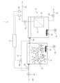
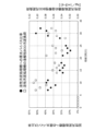
- FIG. 1 is a schematic diagram showing an example of the configuration of a raw water treatment device according to the present embodiment. It is a graph showing the raw water bypass ratio to the activated sludge treatment tank and the daily change of the soluble BOD sludge load with respect to the raw water flow rate in the example.
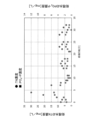
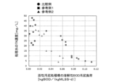
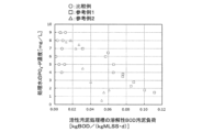
- FIG. 3 is a graph showing daily changes in the total nitrogen concentration (TN concentration) and the phosphate phosphorus concentration (PO 4 -P concentration) in the treated water treated by the membrane separation device of the example. It is a graph showing the relationship between the soluble BOD sludge load of the activated sludge treatment tank and the TN concentration of the treated water in Comparative Examples and Reference Examples 1 and 2.
- 2 is a graph showing the relationship between the soluble BOD sludge load of the activated sludge treatment tank and the PO 4 -P concentration of the treated water in Comparative Examples and Reference Examples 1 and 2.
- FIG. 1 is a schematic diagram showing an example of the configuration of a raw water treatment device according to the present embodiment.
- the raw water treatment device 1 shown in FIG. 1 includes a biological treatment tank 10, a membrane separation activated sludge treatment unit 12, a control device 14, pumps (16a, 16b, 16c), a nitrogen concentration detector 18, and a phosphorus concentration detector. 20, an inflow line (22a, 22b), a bypass line 24, a treated water discharge line 26, a sludge discharge line 28, and a flow rate adjustment valve (30a, 30b).
- the membrane separation activated sludge treatment unit 12 includes an activated sludge treatment tank 32 and a membrane separation device 34.
- the membrane separation device 34 is, for example, a separation membrane module including a separation membrane.
- a membrane separation device 34 is installed within the activated sludge treatment tank 32.
- the inflow line 22a is connected to the biological treatment tank 10. Further, a pump 16a and a flow rate regulating valve 30a are installed in the inflow line 22a. One end of the inflow line 22b is connected to the biological treatment tank 10, and the other end of the inflow line 22b is connected to the activated sludge treatment tank 32. One end of the bypass line 24 is connected to the inflow line 22a, and the other end of the bypass line 24 is connected to the inflow line 22b. Further, a flow rate adjustment valve 30b is installed in the bypass line 24.
- the treated water discharge line 26 is connected to the treated water outlet of the membrane separation device 34. Further, a pump 16b, a nitrogen concentration detector 18, and a phosphorus concentration detector 20 are installed in the treated water discharge line 26.
- the sludge discharge line 28 is connected to an activated sludge treatment tank 32. Further, a pump 16c is installed in the sludge discharge line 28.
- the control device 14 and the flow rate regulating valves (30a, 30b), and the control device 14 and the nitrogen concentration detector 18 and the phosphorus concentration detector 20 are electrically connected.
- the biological treatment tank 10 is filled with carriers 36 holding aerobic microorganisms.
- the aerobic microorganisms held in the carrier 36 are microorganisms that can decompose organic matter in the raw water flowing into the biological treatment tank 10 under aerobic conditions.
- Activated sludge is accommodated in the activated sludge treatment tank 32.
- Activated sludge is sludge containing microorganisms that can decompose organic matter in treated water and raw water flowing into the activated sludge treatment tank 32 under aerobic conditions.
- An aeration device 38 is installed at the bottom of the biological treatment tank 10 and the activated sludge treatment tank 32.
- a blower 40 is connected to the aeration device 38, and the air supplied from the blower 40 is configured to be supplied from the aeration device 38 into the biological treatment tank 10 and the activated sludge treatment tank 32.
- the nitrogen concentration detector 18 may be any device that can detect the nitrogen concentration in the treated water, and examples thereof include a total nitrogen concentration meter (TN meter), an ammonia concentration meter, and the like.
- the phosphorus concentration detector 20 may be any device that can detect the phosphorus concentration in the treated water, and examples thereof include a total phosphorus concentration meter (TP meter), a phosphoric acid concentration meter, and the like.
- the control device 14 is composed of, for example, a microcomputer and an electronic circuit including a CPU for calculating programs, a ROM and a RAM for storing programs and calculation results, and reads out a predetermined program stored in the ROM etc. and executes the corresponding program.
- the program is executed to control the operation of the raw water treatment device 1.
- the control device 14 controls the amount of raw water flowing through the bypass line 24 by controlling the degree of opening and closing of the flow rate regulating valves 30a and 30b based on the nitrogen concentration and phosphorus concentration in the treated water.
- the control device 14 may be configured to control the operation of the pump 16 and the blower 40, for example.
- a flow rate measuring device may be provided in the inflow line 22a and the bypass line 24.
- a total organic carbon meter may be installed in the treated water discharge line 26 in order to check the quality of the treated water.
- the control device 14 operates the pump 16a, opens the flow rate adjustment valve 30a to a predetermined opening degree, and supplies raw water to the biological treatment tank 10 from the inflow line 22a. At this time, the control device 14 may open the flow rate adjustment valve 30b to a predetermined opening degree to cause a portion of the raw water passing through the inflow line 22a to bypass flow into the activated sludge treatment tank 32 from the bypass line 24.
- the control device 14 operates the blower 40 to supply air from the aeration device 38 into the biological treatment tank 10. Then, in the biological treatment tank 10, the organic matter in the raw water is biologically treated by the microorganisms held on the carrier 36 under aerobic conditions. The treated water (first treated water) treated in the biological treatment tank 10 flows into the activated sludge treatment tank 32 through the inflow line 22b.
- control device 14 operates the blower 40 to supply air from the aeration device 38 into the activated sludge treatment tank 32. Then, in the activated sludge treatment tank 32, under aerobic conditions, organic matter in the first treated water flowing in from the inflow line 22b and the raw water bypassed from the bypass line 24 is biologically treated with activated sludge. Further, the control device 14 operates the pump 16b to flow the treated water (second treated water) that has been biologically treated in the activated sludge treatment tank 32 to the membrane separation device 34, and removes the sludge in the second treated water.
- treated water second treated water
- the treated water that has been removed and passed through the separation membrane of the membrane separation device 34 (third treated water: filtrated water from which sludge has been removed) is discharged from the treated water discharge line 26 to the outside of the system. Further, the control device 14 operates the pump 16c to discharge the sludge accumulated in the activated sludge treatment tank 32 from the sludge discharge line 28 to the outside of the system.
- the nitrogen concentration and phosphorus concentration in the third treated water detected by the nitrogen concentration detector 18 and the phosphorus concentration detector 20 are input to the control device 14 .
- the control device 14 then adjusts at least one of the input nitrogen concentration and phosphorus concentration to a predetermined value (the predetermined value may be determined for each of the nitrogen concentration and the phosphorus concentration).
- the opening degrees of the flow rate regulating valves 30a and 30b are controlled so that the amount of raw water flowing through the bypass line 24 increases.
- the opening degrees of the flow rate regulating valves 30a and 30b are controlled so that a predetermined amount of raw water flows into the bypass line 24.
- the flow rate adjustment valve 30a when raw water is flowing into the bypass line 24, the flow rate adjustment valve 30a, The opening degree of 30b is controlled.
- the control device 14 preferably controls the opening degrees of the flow rate regulating valves 30a and 30b so that the amount of raw water flowing through the bypass line 24 decreases.
- the opening degrees of the flow rate regulating valves 30a and 30b are controlled so that the flow of raw water into the bypass line 24 is stopped. Further, for example, the opening degrees of the flow rate adjustment valves 30a and 30b are controlled so that the inflow amount of raw water that is reduced to a predetermined ratio with respect to the current inflow amount of raw water flowing through the bypass line 24 flows through the bypass line 24. .
- the predetermined value is preferably in the range of 0.6 to 1 times the processing target value. Further, in order to stabilize the treatment in the biological treatment reaction tank, it is preferable that the upper limit of the inflow amount of raw water flowing through the bypass line 24 is 90% of the raw water flow rate.
- the treatment progresses in the activated sludge treatment tank 32 in the latter stage than in the biological treatment tank 10 in the former stage, so the BOD volume load of the activated sludge treatment tank 32 in the latter stage must be low.
- nitrogen and phosphorus may be eluted from microbial cells such as activated sludge, or nitrogen and phosphorus that have not been used for microbial cell synthesis may remain, which may deteriorate the quality of the treated water.
- the amount of raw water that bypasses the activated sludge treatment tank 32 is controlled based on the nitrogen concentration and phosphorus concentration of the treated water. It is possible to prevent the BOD volume load from becoming a low load. As a result, it is possible to suppress excessive elution of nitrogen and phosphorus from the bacterial cells of the activated sludge in the activated sludge treatment tank 32, and to suppress the outflow of nitrogen and phosphorus into the treated water.
- the raw water to be treated is, for example, organic wastewater discharged from sewage treatment, food factories, chemical factories, semiconductor factories/LCD factories, pulp and paper factories, and other fields, and biological treatment is not applicable. It's good to have.
- the BOD volumetric load of each of the biological treatment tank 10 and the activated sludge treatment tank 32 should be, for example, 0.5 kg BOD/( m3 ⁇ d) or more in order to further suppress the outflow of nitrogen and phosphorus into the treated water. It is preferably at least 1.0 kgBOD/(m 3 ⁇ d), more preferably at least 1.5 kgBOD/(m 3 ⁇ d).
- the upper limit of the BOD volume load is preferably 6 kg BOD/(m 3 ⁇ d) or less, considering the residual organic matter in the treated water and the outflow of nitrogen and phosphorus.
- the BOD sludge load of the activated sludge treatment tank 32 is preferably in the range of 0.005 to 0.15 kg BOD/(kg MLSS ⁇ d), for example, in order to further suppress the outflow of nitrogen and phosphorus into the treated water.
- the sludge retention time (SRT) of the activated sludge treatment tank 32 depends on the volume load, but is preferably in the range of 5 to 50 days, and more preferably in the range of 20 to 40 days.
- SRT sludge retention time
- the pH of the water in the biological treatment tank 10 and the activated sludge treatment tank 32 is not particularly limited as long as it is within a range suitable for general biological treatment, but is preferably in the range of 6 to 9, for example. The range of 5 to 7.5 is more preferable.
- the pH of the water in the biological treatment tank 10 and the activated sludge treatment tank 32 is adjusted by adding a pH adjuster to each tank.
- the pH adjuster include acid agents such as hydrochloric acid, alkaline agents such as sodium hydroxide, and the like.
- Dissolved oxygen (DO) in the water in the biological treatment tank 10 and activated sludge treatment tank 32 is not particularly limited as long as it is the amount of oxygen necessary for general biological treatment, but for example, it is 0.5 mg/ It is preferably at least 1 mg/L, more preferably at least 1 mg/L.
- the temperature of the water in the biological treatment tank 10 and the activated sludge treatment tank 32 is not particularly limited as long as it is within a range suitable for general biological treatment, but is preferably in the range of 15 to 35°C, for example. A temperature range of 20 to 30°C is more preferable.
- a nitrogen source and/or phosphorus source as nutrients to the biological treatment tank 10.
- a nitrogen source supply line equipped with a first pump and a phosphorus source supply line equipped with a second pump are installed in the biological treatment tank 10. Further, an inflow meter is installed in the bypass line 24 to detect the inflow amount of raw water per unit time.
- the inflow amount per unit time detected by the inflow meter is input to the control device 14, and if the inflow amount is less than a predetermined value, the control device 14 turns on the first pump and the second pump.
- the biological treatment tank 10 is operated to supply a nitrogen source from the nitrogen source supply line and a phosphorus source from the phosphorus source supply line. Then, when the inflow amount exceeds a predetermined value, the control device 14 stops the operation of the first pump and the second pump, and stops the supply of the nitrogen source and the phosphorus source.
- control device 14 may use a map (or formula, table, etc.) that predefines the inflow amount per unit time and the addition amount of the nitrogen source, and the inflow amount per unit time and the addition amount of the phosphorus source. Apply the inflow amount per unit time detected by the inflow meter to a predefined map (or formula, table, etc.) to determine the added amount of nitrogen source and phosphorus source, and calculate the added amount.
- the outputs of the first pump and the second pump are controlled so that the nitrogen source and the phosphorus source are supplied.
- the above map defines a relationship in which the amounts of nitrogen and phosphorus sources added decrease as the amount of inflow increases, and the amounts of nitrogen and phosphorus sources increase as the amount of inflow decreases.
- the nitrogen source is not particularly limited, and examples thereof include ammonium chloride, ammonium sulfate, diammonium hydrogen phosphate, urea, and the like.
- the phosphorus source is not particularly limited, and examples thereof include phosphoric acid, sodium phosphate, potassium phosphate, and the like.
- inorganic salts such as iron, manganese, and calcium may be supplied to the biological treatment tank 10 as nutrients. Note that it is preferable that no nitrogen source or phosphorus source be added to the activated sludge treatment tank 32.
- the carrier 36 in the biological treatment tank 10 may be a conventionally known carrier, such as a plastic carrier, a sponge-like carrier, a gel-like carrier, etc. Among these, a sponge-like carrier is preferable in terms of cost and durability, and for example, a sponge-like carrier made of polyurethane is preferable.
- the carrier 36 is not limited to a fluid type in which it flows within the biological treatment tank 10, but may be a fixed type in which a cartridge or the like filled with the carrier 36 is installed in the biological treatment tank 10.
- the shape of the carrier 36 is not particularly limited, and examples thereof include quadrangular shapes such as cubes, grains, spheres, pellets, cylinders, fibers, and films.
- the amount of carrier 36 added to the biological treatment tank 10 is preferably in the range of 10 to 70% of the tank volume, for example. Note that the carrier 36 may also be introduced into the activated sludge treatment tank 32.
- the membrane separation device 34 of the present embodiment is an immersion type membrane separation device 34 installed inside the activated sludge treatment tank 32, but is not limited to this. type membrane separation device 34 may be used. Among these, it is desirable to adopt the submerged membrane separation device 34 from the viewpoint of the installation area and operating power of the device.
- Examples of the shape of the separation membrane installed in the membrane separation device 34 include a flat membrane type, hollow fiber type, tubular type, and spiral type.
- the material of the immersion membrane is, for example, polyethylene (PE), polyvinylidene fluoride (PVDF), polytetrafluoroethylene (PTFE), polyvinyl chloride (PVC), polyethersulfone (PES), cellulose acetate (CA), etc.
- Examples include organic membranes and inorganic membranes made of ceramic.
- the pore size of the separation membrane is, for example, preferably 1.0 ⁇ m or less, and preferably a microfiltration membrane or ultrafiltration membrane with a pore size of 0.1 ⁇ m or less.
- the permeation flow rate of the separation membrane is preferably operated within a range of, for example, 0.1 to 0.8 m/day, more preferably within a range of 0.2 to 0.6 m/day.
- an inorganic flocculant to the activated sludge treatment tank 32.
- an inorganic flocculant supply line equipped with a pump is installed in the activated sludge treatment tank 32.
- the control device 14 operates the pump to supply the inorganic flocculant from the inorganic flocculant supply line to the activated sludge treatment tank. 32. Such operations can quickly reduce the phosphorus concentration in the treated water.
- the inorganic flocculant may be any conventionally known flocculant, such as polyaluminum chloride (PAC), ferric chloride, and the like.
- the amount of the inorganic flocculant added is preferably greater than the theoretically required amount.
- Example> A continuous flow test of simulated wastewater (raw water) was conducted using the raw water treatment equipment shown in FIG. 1. However, no control device was used, and the opening/closing control of the flow rate adjustment valve and the operation control of the pump were performed manually. In addition, an acclimatization step was provided before conducting the continuous water flow test. Specifically, raw water was passed only through the biological treatment tank, and while checking the BOD concentration of the treated water, the BOD volume load was increased and microorganisms were sufficiently attached to the carrier. After this acclimatization process, a continuous water flow test was started by combining the biological treatment tank with the membrane-separated activated sludge treatment unit. Activated sludge that had been acclimatized with raw water was put into the activated sludge treatment tank.
- Biological treatment tank volume 12L
- Carrier of biological treatment tank Hydrophobic polyurethane sponge carrier
- Filling rate of carrier of biological treatment tank 20% filling as bulk volume
- Separation membrane of membrane separation device PVDF hollow fiber membrane Filtration flux of membrane separation device: 0.4 m/d *Filtration flux is the amount of water processed per unit membrane area of a separation membrane, and is calculated as follows.
- Filtration flux raw water flow rate ⁇ membrane area of separation membrane Volume of activated sludge treatment tank: 24L Sludge concentration (MLSS) in activated sludge treatment tank: 8000mg/L Sludge withdrawal from activated sludge treatment tank: Sludge is withdrawn once a day so that MLSS is 8000 mg/L.
- Sludge concentration 8000mg/L
- the soluble BOD removal rate of the biological treatment tank was 95% or more during all experimental periods, and the ammonia nitrogen concentration and phosphate phosphorus concentration were also removed by 95% or more.
- the soluble BOD concentration in the biological treatment tank is the BOD concentration after filtering with a 0.45 ⁇ m filter to remove suspended components.
- FIG. 2 shows the daily changes in the raw water bypass ratio to the activated sludge treatment tank and the soluble BOD sludge load with respect to the raw water flow rate in the example.
- FIG. 3 shows the daily changes in the total nitrogen concentration (TN concentration) and the phosphate phosphorus concentration (PO 4 -P concentration) in the treated water treated by the membrane separation device of the example.
- TN concentration total nitrogen concentration
- PO 4 -P concentration phosphate phosphorus concentration
- the raw water BOD concentration was set to 1000 mg/L from the start of water flow to the 18th day, the raw water BOD concentration was set to 1500 mg/L from the 19th to the 25th day, and thereafter the raw water BOD concentration was set to 500 mg/L. .
- the target values in this experiment were TN concentration: 10 mg/L or less, and PO 4 -P: 2 mg/L or less.
- the TN concentration and PO 4 -P concentration of the treated water treated by the membrane separation device increase.
- the target value was exceeded. Since the TN concentration and PO 4 -P concentration of the treated water exceeded the target values, during the period from 7th to 11th day, the raw water bypass ratio to the activated sludge treatment tank was set to 28% to 39%, and the raw water was transferred to the activated sludge treatment tank.
- the TN concentration and PO 4 -P concentration of the treated water could be brought to the target values.
- the soluble BOD sludge load in the activated sludge treatment tank remained at 0.08 to 0.1 kgBOD/(kgMLSS ⁇ d).
- operation was carried out with the raw water bypass ratio to the activated sludge treatment tank reduced to 17 to 22%, and although the TN and PO 4 -P concentrations in the treated water increased, they still reached the target. were able to maintain the value.
- the soluble BOD sludge load in the activated sludge treatment tank remained at 0.05 to 0.06 kg BOD/(kg MLSS ⁇ d).
- the operation was performed with the raw water BOD concentration varied, but even if the raw water concentration fluctuated, the raw water bypassed into the activated sludge treatment tank was adjusted according to the TN concentration and PO 4 -P concentration of the treated water.
- the inflow rate i.e. raw water bypass ratio to the activated sludge treatment tank
- the soluble BOD sludge load to the activated sludge treatment tank during the experiment period varied from 0.03 to 0.11 kg BOD/(kg MLSS ⁇ d).
- FIG. 4 shows the relationship between the soluble BOD sludge load in the activated sludge treatment tank and the TN concentration in the treated water in Comparative Example, Reference Examples 1 and 2.
- FIG. 5 shows the relationship between the soluble BOD sludge load in the activated sludge treatment tank and the PO 4 -P concentration in the treated water in Comparative Examples and Reference Examples 1 and 2.
- the soluble BOD sludge load in the activated sludge treatment tank was less than 0.02 kg BOD/(kg MLSS ⁇ d)
- the TN concentration in the treated water was 20 mg/L or more
- the PO 4 -P concentration was 4 mg/L or more. It remained at .
- the soluble BOD sludge load required to set the TN concentration and PO 4 -P concentration to the target values is 0.1 kgBOD/(kgMLSS ⁇ d) or more in Reference Example 1 and 0.05 kgBOD/in Reference Example 2. (kgMLSS ⁇ d) or more, each having a different numerical range. Therefore, in order to manage the soluble BOD sludge load, it is necessary to grasp the numerical range in which the target water quality can be obtained in advance or during actual operation. However, since the range is thought to vary depending on the operating conditions, it is assumed that it is difficult to manage the soluble BOD sludge load during actual operation.
- Table 1 shows the daily increase in suction pressure of the separation membrane, the sludge retention time in the activated sludge treatment tank, and the BOD sludge conversion rate during the operation period of Examples, Comparative Examples, and Reference Examples 1 and 2.
- Comparative examples in which raw water does not flow into the activated sludge treatment tank by bypass have a lower BOD sludge conversion rate than Examples in which raw water flows by bypass. This is because by not implementing bypass inflow of raw water, the organic matter load in the activated sludge treatment tank was lowered and sludge decomposition progressed. As a result, it appears that in the comparative example, the sludge retention time became longer and substances that promote membrane clogging, such as biopolymers, accumulated, resulting in a larger amount of increase in suction pressure per day. On the other hand, in the examples in which bypass inflow of raw water was performed, no significant increase in suction pressure was observed.
Landscapes
- Life Sciences & Earth Sciences (AREA)
- Water Supply & Treatment (AREA)
- Hydrology & Water Resources (AREA)
- Engineering & Computer Science (AREA)
- Environmental & Geological Engineering (AREA)
- Chemical & Material Sciences (AREA)
- Organic Chemistry (AREA)
- Biodiversity & Conservation Biology (AREA)
- Microbiology (AREA)
- Health & Medical Sciences (AREA)
- Molecular Biology (AREA)
- Purification Treatments By Anaerobic Or Anaerobic And Aerobic Bacteria Or Animals (AREA)
- Separation Using Semi-Permeable Membranes (AREA)
- Activated Sludge Processes (AREA)
Abstract
Description
図1に示す原水処理装置を用いて、模擬廃水(原水)の連続通水試験を実施した。但し、制御装置は使用せず、流量調整弁の開閉制御、ポンプの稼働制御は手動で行った。また、連続通水試験を実施する前には、馴養工程を設けた。具体的には、生物処理槽のみに原水を通水し、処理水BOD濃度を確認しながら、BOD容積負荷を増加させつつ、担体に十分に微生物を付着させた。この馴養工程後の生物処理槽と膜分離活性汚泥処理ユニットとを組み合わせて連続通水試験を開始した。なお、活性汚泥処理槽には本原水で馴養された活性汚泥を投入した。
生物処理槽の容積:12L
生物処理槽の担体:疎水性ポリウレタン製のスポンジ担体
生物処理槽の担体充填率:嵩体積として20%充填
膜分離装置の分離膜:PVDF中空糸膜
膜分離装置のろ過Flux:0.4m/d
※ろ過Fluxとは分離膜の単位膜面積当たりの処理水量であり、以下のように算出される。ろ過Flux=原水流量÷分離膜の膜面積
活性汚泥処理槽の容積:24L
活性汚泥処理槽の汚泥濃度(MLSS):8000mg/L
活性汚泥処理槽の汚泥の引抜:MLSSが8000mg/Lとなるように一日に1回汚泥を引き抜く。
原水BOD濃度の代表値:500、1000、1500mg/L(後述する比較例、参考例1、2:1000mg/L)
原水中の基質:スクロース、酢酸ナトリウム、プロピオン酸、2-プロパノール
原水中の窒素及びリン:塩化アンモニウムとリン酸を用いてBOD:N:P=100:5:1となるように調整
その他必要な微量元素:微量元素溶液を原水に添加
原水SS:無し
原水流量:54L/d(活性汚泥処理槽に適宜バイパス)
全体BOD容積負荷:1.5kgBOD/(m3・d)
※全体BOD容積負荷は以下のようにして算出される。全体BOD容積負荷=原水BOD濃度×流入水量÷生物処理槽と活性汚泥処理槽の合計槽容積
生物処理槽の溶解性BOD除去率=(原水BOD濃度-生物処理槽の溶解性BOD濃度)÷原水BOD濃度
なお、原水にはSSが無いことから原水BOD=溶解性BODである。生物処理槽の溶解性BOD濃度は0.45μmフィルターでろ過して、懸濁成分を除去した後のBOD濃度である。
(1)活性汚泥処理槽の溶解性BOD汚泥負荷=((生物処理槽の溶解性BOD濃度×生物処理槽への原水流量)+(活性汚泥処理槽への原水のバイパス流入量×原水溶解性BOD濃度))÷(槽内汚泥濃度×槽容積)
なお、原水にはSSが無いことから原水BOD=溶解性BODである。
(2)活性汚泥処理槽の汚泥滞留時間=(槽内汚泥濃度×槽容積)÷(引抜汚泥濃度×引抜水量)
(3)BOD汚泥転換率=活性汚泥処理槽の発生汚泥量÷全体BOD除去量
(4)活性汚泥処理槽の発生汚泥量=((所定期間経過後の活性汚泥処理槽の汚泥濃度-初期の活性汚泥処理槽の汚泥濃度)×活性汚泥処理槽の槽容積)+(引抜汚泥濃度×引抜水量)
(5)全体BOD除去量=(原水BOD濃度-活性汚泥処理槽の膜分離処理水のBOD濃度)×原水流量
(6)吸引圧力は、処理水排出ラインに設置した圧力計(長野計器社製、GC67型)により測定した値である。吸引圧力はロギングし、所定期間における1日当たりの吸引圧力上昇量として示した。
比較例では、原水を活性汚泥処理槽へバイパス流入させないこと以外は実施例と同様に試験した。また、参考例1、2では、原水を活性汚泥処理槽へバイパス流入させたが、処理水のTN濃度及びPO4-P濃度に応じて原水バイパス比率を制御せず、単純に原水バイパス比率を増やす制御を行った。それ以外は、実施例と同様に試験した。参考例1と2では、活性汚泥処理槽の汚泥滞留時間が異なること以外は同じ条件である。活性汚泥処理槽の汚泥滞留時間において、参考例1を30日とし、参考例2を40日とした。

Claims (6)
- 好気性微生物を保持した担体を収容する生物処理槽と、前記生物処理槽で生物処理された第1処理水が流入すると共に、活性汚泥を収容する活性汚泥処理槽及び前記活性汚泥処理槽で生物処理された第2処理水を膜処理する膜分離装置を備える膜分離活性汚泥処理ユニットとを備える原水処理装置を用いて原水を処理する原水処理工程と、
前記生物処理槽を介さずに前記原水の一部を前記活性汚泥処理槽にバイパス流入させる流入工程と、を有し、
前記流入工程では、前記膜分離装置で処理された第3処理水中の窒素濃度及びリン濃度に基づいて、前記バイパス流入させる前記原水の流入量を制御することを特徴とする原水処理方法。 - 前記生物処理槽に窒素源及び/又はリン源を添加する窒素源・リン源添加工程を有し、
前記添加工程では、前記バイパス流入させる前記原水の流入量に基づいて、前記窒素源及び/又は前記リン源の添加量を制御することを特徴とする請求項1に記載の原水処理方法。 - 前記膜分離装置で処理された前記第3処理水中の前記リン濃度が、所定値以上の場合には、前記活性汚泥処理槽に無機凝集剤を添加する無機凝集剤添加工程を有することを特徴とする請求項1又は2に記載の原水処理方法。
- 原水を処理する原水処理装置であって、
好気性微生物を担持した担体を収容する生物処理槽と、
前記生物処理槽で生物処理された第1処理水が流入すると共に、活性汚泥を収容する活性汚泥処理槽、及び前記活性汚泥処理槽で生物処理された第2処理水を膜処理する膜分離装置を備える膜分離活性汚泥処理ユニットと、
前記生物処理槽を介さずに前記原水の一部を前記活性汚泥処理槽にバイパス流入させるバイパスラインと、
前記膜分離装置で処理された第3処理水中の窒素濃度及びリン濃度に基づいて、前記バイパスラインを流れる前記原水の流入量を制御する制御部と、を有することを特徴とする原水処理装置。 - 前記生物処理槽に窒素源及び/又はリン源を添加する窒素源・リン源添加手段を有し、
前記窒素源・リン源添加手段は、前記バイパスラインを流れる前記原水の流入量に基づいて、前記窒素源及び/又は前記リン源の添加量を制御することを特徴とする請求項4に記載の原水処理装置。 - 前記活性汚泥処理槽に無機凝集剤を添加する無機凝集剤添加手段を有し、
前記無機凝集剤添加手段は、前記膜分離装置で処理された前記第3処理水中の前記リン濃度が所定値以上の場合に、前記活性汚泥処理槽に前記無機凝集剤を添加することを特徴とする請求項4又は5に記載の原水処理装置。
Priority Applications (2)
| Application Number | Priority Date | Filing Date | Title |
|---|---|---|---|
| CN202380043980.0A CN119301079A (zh) | 2022-06-09 | 2023-04-26 | 原水处理方法及原水处理装置 |
| US18/871,321 US20250320143A1 (en) | 2022-06-09 | 2023-04-26 | Raw water treatment method and raw water treatment device |
Applications Claiming Priority (2)
| Application Number | Priority Date | Filing Date | Title |
|---|---|---|---|
| JP2022-093960 | 2022-06-09 | ||
| JP2022093960A JP2023180565A (ja) | 2022-06-09 | 2022-06-09 | 原水処理方法及び原水処理装置 |
Publications (1)
| Publication Number | Publication Date |
|---|---|
| WO2023238545A1 true WO2023238545A1 (ja) | 2023-12-14 |
Family
ID=89118087
Family Applications (1)
| Application Number | Title | Priority Date | Filing Date |
|---|---|---|---|
| PCT/JP2023/016543 Ceased WO2023238545A1 (ja) | 2022-06-09 | 2023-04-26 | 原水処理方法及び原水処理装置 |
Country Status (5)
| Country | Link |
|---|---|
| US (1) | US20250320143A1 (ja) |
| JP (1) | JP2023180565A (ja) |
| CN (1) | CN119301079A (ja) |
| TW (1) | TW202408946A (ja) |
| WO (1) | WO2023238545A1 (ja) |
Citations (5)
| Publication number | Priority date | Publication date | Assignee | Title |
|---|---|---|---|---|
| JP2000325991A (ja) * | 1999-05-24 | 2000-11-28 | Mitsubishi Electric Corp | 生物学的水処理装置の制御装置 |
| JP2003170185A (ja) * | 2001-12-11 | 2003-06-17 | Takane Kitao | ろ過装置を備えた浄化槽及びろ材による被処理水の浄化方法 |
| JP2016002514A (ja) * | 2014-06-16 | 2016-01-12 | 株式会社日立製作所 | 膜分離活性汚泥処理装置及びその運転方法 |
| JP2016123920A (ja) * | 2014-12-26 | 2016-07-11 | オルガノ株式会社 | 排水処理装置及び排水処理方法 |
| JP2022010607A (ja) * | 2020-06-29 | 2022-01-17 | 前澤工業株式会社 | 汚水処理装置及び汚水処理方法 |
Family Cites Families (1)
| Publication number | Priority date | Publication date | Assignee | Title |
|---|---|---|---|---|
| JP7587943B2 (ja) * | 2020-09-02 | 2024-11-21 | オルガノ株式会社 | 有機性排水の処理方法及び有機性排水の処理装置 |
-
2022
- 2022-06-09 JP JP2022093960A patent/JP2023180565A/ja active Pending
-
2023
- 2023-04-26 US US18/871,321 patent/US20250320143A1/en active Pending
- 2023-04-26 WO PCT/JP2023/016543 patent/WO2023238545A1/ja not_active Ceased
- 2023-04-26 CN CN202380043980.0A patent/CN119301079A/zh active Pending
- 2023-06-07 TW TW112121149A patent/TW202408946A/zh unknown
Patent Citations (5)
| Publication number | Priority date | Publication date | Assignee | Title |
|---|---|---|---|---|
| JP2000325991A (ja) * | 1999-05-24 | 2000-11-28 | Mitsubishi Electric Corp | 生物学的水処理装置の制御装置 |
| JP2003170185A (ja) * | 2001-12-11 | 2003-06-17 | Takane Kitao | ろ過装置を備えた浄化槽及びろ材による被処理水の浄化方法 |
| JP2016002514A (ja) * | 2014-06-16 | 2016-01-12 | 株式会社日立製作所 | 膜分離活性汚泥処理装置及びその運転方法 |
| JP2016123920A (ja) * | 2014-12-26 | 2016-07-11 | オルガノ株式会社 | 排水処理装置及び排水処理方法 |
| JP2022010607A (ja) * | 2020-06-29 | 2022-01-17 | 前澤工業株式会社 | 汚水処理装置及び汚水処理方法 |
Non-Patent Citations (1)
| Title |
|---|
| BAI YANG, QUAN XIE, ZHANG YAOBIN, CHEN SHUO: "Enhancing nitrogen and phosphorus removal in the BUCT–IFAS process by bypass flow strategy", WATER SCIENCE & TECHNOLOGY, vol. 72, no. 4, 1 August 2015 (2015-08-01), pages 528 - 534, XP009551163, ISSN: 0273-1223, DOI: 10.2166/wst.2015.242 * |
Also Published As
| Publication number | Publication date |
|---|---|
| JP2023180565A (ja) | 2023-12-21 |
| CN119301079A (zh) | 2025-01-10 |
| US20250320143A1 (en) | 2025-10-16 |
| TW202408946A (zh) | 2024-03-01 |
Similar Documents
| Publication | Publication Date | Title |
|---|---|---|
| US9856160B2 (en) | Biological two-stage contaminated water treatment system | |
| WO2000027756A1 (en) | Water treating method | |
| JP2014061486A (ja) | 水処理方法および水処理システム | |
| JP2014065008A (ja) | 水処理方法および水処理システム | |
| JP5782931B2 (ja) | 水処理方法及び水処理装置 | |
| JP2001334285A (ja) | 有機性排水の生物処理装置 | |
| JP2022042385A (ja) | 有機性排水の処理方法及び有機性排水の処理装置 | |
| CN115968357B (zh) | 有机性排水的处理方法以及有机性排水的处理装置 | |
| JP2011200767A (ja) | 排水処理方法および排水処理システム | |
| JP4997724B2 (ja) | 有機性排水の処理方法 | |
| WO2023238545A1 (ja) | 原水処理方法及び原水処理装置 | |
| JP7173718B2 (ja) | 排水処理方法及び排水処理装置 | |
| KR100882230B1 (ko) | 축산 폐수 처리 장치 및 그 처리 방법 | |
| JP7718882B2 (ja) | 有機性排水の処理方法および有機性排水の処理装置 | |
| JP4101539B2 (ja) | 排水処理装置 | |
| Krauth | Sustainable sewage treatment plants—application of nanofiltration and ultrafiltration to a pressurized bioreactor | |
| JP7587942B2 (ja) | 有機性排水の処理方法及び有機性排水の処理装置 | |
| JP2023022723A (ja) | 排水処理装置及び排水処理方法 | |
| CN107848850A (zh) | 生物处理装置 | |
| KR100882228B1 (ko) | 과염소산염을 포함한 폐수의 처리 장치 및 그 처리 방법 | |
| JP2003094091A (ja) | 硝酸性窒素の除去装置 | |
| US9862629B2 (en) | Anoxic membrane filtration system | |
| CN114906924A (zh) | 水处理方法以及水处理装置 | |
| JP4894791B2 (ja) | 有機物含有水の生物処理方法および装置 | |
| HK1198331B (en) | Biological two-stage contaminated water treatment system |
Legal Events
| Date | Code | Title | Description |
|---|---|---|---|
| 121 | Ep: the epo has been informed by wipo that ep was designated in this application |
Ref document number: 23819532 Country of ref document: EP Kind code of ref document: A1 |
|
| WWE | Wipo information: entry into national phase |
Ref document number: 202380043980.0 Country of ref document: CN |
|
| WWE | Wipo information: entry into national phase |
Ref document number: 18871321 Country of ref document: US |
|
| NENP | Non-entry into the national phase |
Ref country code: DE |
|
| WWP | Wipo information: published in national office |
Ref document number: 202380043980.0 Country of ref document: CN |
|
| 122 | Ep: pct application non-entry in european phase |
Ref document number: 23819532 Country of ref document: EP Kind code of ref document: A1 |
|
| WWP | Wipo information: published in national office |
Ref document number: 18871321 Country of ref document: US |