WO2023238319A1 - 加工システム及び加工方法 - Google Patents
加工システム及び加工方法 Download PDFInfo
- Publication number
- WO2023238319A1 WO2023238319A1 PCT/JP2022/023275 JP2022023275W WO2023238319A1 WO 2023238319 A1 WO2023238319 A1 WO 2023238319A1 JP 2022023275 W JP2022023275 W JP 2022023275W WO 2023238319 A1 WO2023238319 A1 WO 2023238319A1
- Authority
- WO
- WIPO (PCT)
- Prior art keywords
- molten pool
- processing
- imaging
- energy beam
- processing system
- Prior art date
- Legal status (The legal status is an assumption and is not a legal conclusion. Google has not performed a legal analysis and makes no representation as to the accuracy of the status listed.)
- Ceased
Links
Images










Classifications
-
- B—PERFORMING OPERATIONS; TRANSPORTING
- B23—MACHINE TOOLS; METAL-WORKING NOT OTHERWISE PROVIDED FOR
- B23K—SOLDERING OR UNSOLDERING; WELDING; CLADDING OR PLATING BY SOLDERING OR WELDING; CUTTING BY APPLYING HEAT LOCALLY, e.g. FLAME CUTTING; WORKING BY LASER BEAM
- B23K26/00—Working by laser beam, e.g. welding, cutting or boring
- B23K26/02—Positioning or observing the workpiece, e.g. with respect to the point of impact; Aligning, aiming or focusing the laser beam
- B23K26/06—Shaping the laser beam, e.g. by masks or multi-focusing
- B23K26/0604—Shaping the laser beam, e.g. by masks or multi-focusing by a combination of beams
-
- B—PERFORMING OPERATIONS; TRANSPORTING
- B22—CASTING; POWDER METALLURGY
- B22F—WORKING METALLIC POWDER; MANUFACTURE OF ARTICLES FROM METALLIC POWDER; MAKING METALLIC POWDER; APPARATUS OR DEVICES SPECIALLY ADAPTED FOR METALLIC POWDER
- B22F10/00—Additive manufacturing of workpieces or articles from metallic powder
- B22F10/20—Direct sintering or melting
- B22F10/25—Direct deposition of metal particles, e.g. direct metal deposition [DMD] or laser engineered net shaping [LENS]
-
- B—PERFORMING OPERATIONS; TRANSPORTING
- B22—CASTING; POWDER METALLURGY
- B22F—WORKING METALLIC POWDER; MANUFACTURE OF ARTICLES FROM METALLIC POWDER; MAKING METALLIC POWDER; APPARATUS OR DEVICES SPECIALLY ADAPTED FOR METALLIC POWDER
- B22F10/00—Additive manufacturing of workpieces or articles from metallic powder
- B22F10/30—Process control
- B22F10/36—Process control of energy beam parameters
- B22F10/366—Scanning parameters, e.g. hatch distance or scanning strategy
-
- B—PERFORMING OPERATIONS; TRANSPORTING
- B22—CASTING; POWDER METALLURGY
- B22F—WORKING METALLIC POWDER; MANUFACTURE OF ARTICLES FROM METALLIC POWDER; MAKING METALLIC POWDER; APPARATUS OR DEVICES SPECIALLY ADAPTED FOR METALLIC POWDER
- B22F10/00—Additive manufacturing of workpieces or articles from metallic powder
- B22F10/30—Process control
- B22F10/36—Process control of energy beam parameters
- B22F10/368—Temperature or temperature gradient, e.g. temperature of the melt pool
-
- B—PERFORMING OPERATIONS; TRANSPORTING
- B22—CASTING; POWDER METALLURGY
- B22F—WORKING METALLIC POWDER; MANUFACTURE OF ARTICLES FROM METALLIC POWDER; MAKING METALLIC POWDER; APPARATUS OR DEVICES SPECIALLY ADAPTED FOR METALLIC POWDER
- B22F12/00—Apparatus or devices specially adapted for additive manufacturing; Auxiliary means for additive manufacturing; Combinations of additive manufacturing apparatus or devices with other processing apparatus or devices
- B22F12/40—Radiation means
- B22F12/49—Scanners
-
- B—PERFORMING OPERATIONS; TRANSPORTING
- B22—CASTING; POWDER METALLURGY
- B22F—WORKING METALLIC POWDER; MANUFACTURE OF ARTICLES FROM METALLIC POWDER; MAKING METALLIC POWDER; APPARATUS OR DEVICES SPECIALLY ADAPTED FOR METALLIC POWDER
- B22F12/00—Apparatus or devices specially adapted for additive manufacturing; Auxiliary means for additive manufacturing; Combinations of additive manufacturing apparatus or devices with other processing apparatus or devices
- B22F12/90—Means for process control, e.g. cameras or sensors
-
- B—PERFORMING OPERATIONS; TRANSPORTING
- B23—MACHINE TOOLS; METAL-WORKING NOT OTHERWISE PROVIDED FOR
- B23K—SOLDERING OR UNSOLDERING; WELDING; CLADDING OR PLATING BY SOLDERING OR WELDING; CUTTING BY APPLYING HEAT LOCALLY, e.g. FLAME CUTTING; WORKING BY LASER BEAM
- B23K26/00—Working by laser beam, e.g. welding, cutting or boring
- B23K26/02—Positioning or observing the workpiece, e.g. with respect to the point of impact; Aligning, aiming or focusing the laser beam
- B23K26/03—Observing, e.g. monitoring, the workpiece
- B23K26/032—Observing, e.g. monitoring, the workpiece using optical means
-
- B—PERFORMING OPERATIONS; TRANSPORTING
- B23—MACHINE TOOLS; METAL-WORKING NOT OTHERWISE PROVIDED FOR
- B23K—SOLDERING OR UNSOLDERING; WELDING; CLADDING OR PLATING BY SOLDERING OR WELDING; CUTTING BY APPLYING HEAT LOCALLY, e.g. FLAME CUTTING; WORKING BY LASER BEAM
- B23K26/00—Working by laser beam, e.g. welding, cutting or boring
- B23K26/08—Devices involving relative movement between laser beam and workpiece
- B23K26/082—Scanning systems, i.e. devices involving movement of the laser beam relative to the laser head
-
- B—PERFORMING OPERATIONS; TRANSPORTING
- B23—MACHINE TOOLS; METAL-WORKING NOT OTHERWISE PROVIDED FOR
- B23K—SOLDERING OR UNSOLDERING; WELDING; CLADDING OR PLATING BY SOLDERING OR WELDING; CUTTING BY APPLYING HEAT LOCALLY, e.g. FLAME CUTTING; WORKING BY LASER BEAM
- B23K26/00—Working by laser beam, e.g. welding, cutting or boring
- B23K26/34—Laser welding for purposes other than joining
- B23K26/342—Build-up welding
-
- B—PERFORMING OPERATIONS; TRANSPORTING
- B33—ADDITIVE MANUFACTURING TECHNOLOGY
- B33Y—ADDITIVE MANUFACTURING, i.e. MANUFACTURING OF THREE-DIMENSIONAL [3D] OBJECTS BY ADDITIVE DEPOSITION, ADDITIVE AGGLOMERATION OR ADDITIVE LAYERING, e.g. BY 3D PRINTING, STEREOLITHOGRAPHY OR SELECTIVE LASER SINTERING
- B33Y30/00—Apparatus for additive manufacturing; Details thereof or accessories therefor
-
- B—PERFORMING OPERATIONS; TRANSPORTING
- B33—ADDITIVE MANUFACTURING TECHNOLOGY
- B33Y—ADDITIVE MANUFACTURING, i.e. MANUFACTURING OF THREE-DIMENSIONAL [3D] OBJECTS BY ADDITIVE DEPOSITION, ADDITIVE AGGLOMERATION OR ADDITIVE LAYERING, e.g. BY 3D PRINTING, STEREOLITHOGRAPHY OR SELECTIVE LASER SINTERING
- B33Y50/00—Data acquisition or data processing for additive manufacturing
- B33Y50/02—Data acquisition or data processing for additive manufacturing for controlling or regulating additive manufacturing processes
Definitions
- Patent Document 1 An example of a processing system for processing an object is described in Patent Document 1.
- One of the technical challenges for such processing systems is properly processing objects.
- a processing head forms a molten pool on the object by irradiating the object with an energy beam and processes the object by supplying a modeling material to the molten pool
- the processing head a processing device equipped with a position change device capable of changing the irradiation position of the energy beam on the processing head; and a processing device that is attached to the processing head and capable of generating a molten pool image by capturing an image of the molten pool formed by the processing device.
- generating molten pool image information based on the molten pool image generated by the imaging device; and processing the molten pool area so that the size of the molten pool region becomes a target size based on the molten pool image information.
- a processing system is provided, including a control device that controls the device, and in which the molten pool image information is generated based on a plurality of the molten pool images captured by the imaging device.
- a processing device that forms a molten pool on the object by irradiating the object with an energy beam and processes the object by supplying a modeling material to the molten pool; an imaging device capable of generating a molten pool image by capturing an image of a control device that controls the processing device so that the size of the molten pool region becomes a target size, the control device changing the predetermined threshold value based on conditions for processing the object by the processing device; system is provided.
- a processing device that forms a molten pool on the object by irradiating the object with an energy beam and processes the object by supplying a modeling material to the molten pool;
- An imaging device capable of generating multiple images by capturing an area including the area multiple times, and a comparison result of adding signal values for each pixel of the multiple images and comparing the addition result for each pixel with a predetermined threshold value.
- a processing device that forms a molten pool on the object by irradiating the object with an energy beam and processes the object by supplying a modeling material to the molten pool; an imaging device capable of generating a molten pool image by capturing an image; and an imaging device capable of generating a molten pool image by capturing an image of the molten pool, and generating molten pool image information based on the molten pool image generated by the imaging device;
- a control device that controls the processing device so that the size becomes a target size, and a recording device that records information regarding the target size of the molten pool in association with wobble conditions of the energy beam, the control device comprising:
- a processing system is provided that controls the processing device based on a target size of the molten pool obtained from the recording device.
- a processing device that forms a molten pool on the object by irradiating the object with an energy beam and processes the object by supplying a modeling material to the molten pool; an imaging device capable of generating a molten pool image by imaging the molten pool; and a control device, the control device continuously moving the energy beam to different positions based on the molten pool image generated by the imaging device.
- a processing system that is capable of acquiring shape information regarding a molten pool that is formed in a conventional manner, and that controls the processing device based on the shape information.
- a processing device that forms a molten pool on the object by irradiating the object with an energy beam and processes the object by supplying a modeling material to the molten pool; an imaging device capable of generating a molten pool image by imaging the molten pool; and a control device, the control device continuously moving the energy beam to different positions based on the molten pool image generated by the imaging device.
- a processing system that is capable of acquiring center position information of a molten pool that is formed in a conventional manner, and that controls the processing apparatus based on the center position information.
- a processing head forms a molten pool on the object by irradiating the object with an energy beam and processes the object by supplying a modeling material to the molten pool
- the processing head a processing device equipped with a position change device capable of changing the irradiation position of the energy beam on the processing head; and a processing device that is attached to the processing head and capable of generating a molten pool image by capturing an image of the molten pool formed by the processing device.
- generating molten pool image information based on the molten pool image generated by the imaging device; and processing the molten pool area so that the size of the molten pool region becomes a target size based on the molten pool image information.
- a processing system is provided, including a control device that controls the device, and the molten pool image information is generated based on multiple exposure by the imaging device.
- a processing device that irradiates an energy beam onto an object to form a molten pool on the object, an imaging device capable of generating a molten pool image by imaging the molten pool, and the imaging device a control device that generates molten pool image information based on the molten pool image generated by the molten pool image and controls the processing device based on the molten pool image information, and the molten pool image information is generated by the imaging device. It is generated based on the plurality of captured images of the molten pool, and the control device changes the imaging conditions for the imaging device to image the molten pool based on the processing conditions of the object by the processing device.
- a processing system is provided.
- a processing device that processes the object by irradiating the object with an energy beam to form a molten pool on the object, and a processing device capable of generating a molten pool image by capturing an image of the molten pool.
- an imaging device ; and a processing device that generates molten pool image information based on the molten pool image generated by the imaging device, and adjusts the size of the molten pool region to a target size based on the molten pool image information.
- a processing system comprising: a control device for controlling the target size, wherein the control device changes the target size based on conditions for processing the object by the processing device.
- a processing apparatus that processes the object by irradiating the object with an energy beam to form a molten pool on the object; an image capturing device capable of generating an image of the molten pool area in the image, and at least one of emitted light and reflected light other than the molten pool, based on the addition result of signal values for each pixel of the plurality of images.
- a processing system is provided that includes a control device that detects at least one of a non-molten pool region and a non-molten pool region.
- a processing device that processes the object by irradiating the object with an energy beam to form a molten pool on the object, and a processing device capable of generating a molten pool image by capturing an image of the molten pool.
- an imaging device a control device that generates molten pool image information based on the molten pool image generated by the imaging device and controls the processing device based on the molten pool image information, and wobble conditions for the energy beam.
- a recording device that records information regarding the target size of the molten pool, the control device controlling the processing system that controls the processing device based on the target size of the molten pool obtained from the recording device.
- a processing device that processes the object by irradiating the object with an energy beam to form a molten pool on the object, and a processing device capable of generating a molten pool image by capturing an image of the molten pool.
- the method includes an imaging device and a control device, and the control device acquires shape information regarding the molten pool continuously formed at different positions by the energy beam based on the molten pool image generated by the imaging device.
- a processing system is provided that controls the processing apparatus based on the shape information.
- a processing device that processes the object by irradiating the object with an energy beam to form a molten pool on the object, and a processing device capable of generating a molten pool image by capturing an image of the molten pool.
- the control device includes an imaging device and a control device, and the control device obtains center position information of the molten pool successively formed at different positions by the energy beam based on the molten pool image generated by the imaging device.
- a processing system is provided that controls the processing device based on the center position information.
- a processing device that processes the object by irradiating the object with an energy beam to form a molten pool on the object, and a processing device capable of generating a molten pool image by capturing an image of the molten pool.
- an imaging device a control device that generates molten pool image information based on the molten pool image generated by the imaging device and controls the processing device based on the molten pool image information; The information is generated based on the molten pool image generated by multiple exposure by the imaging device, and the control device adjusts the conditions for the multiple exposure by the imaging device based on the processing conditions of the object by the processing device.
- a processing system is provided for changing the.
- a processing head that processes the object by irradiating the object with an energy beam to form a molten pool on the object, and a position where the irradiation position of the energy beam relative to the processing head can be changed.
- a processing device including a changing device; an imaging device that is attached to the processing head and is capable of generating a molten pool image by capturing an image of the molten pool formed by the processing device; a control device that generates molten pool image information based on the molten pool image and controls the processing device based on the molten pool image information, and the molten pool image information is generated based on multiple exposure by the imaging device.
- a processing system is provided that generates the following information.
- a processing device that forms a molten pool on the object by irradiating the object with an energy beam and forms a shaped object on the object along a target trajectory; and a processing device that images the molten pool. and a control device that controls the processing device based on the molten pool image generated by the imaging device, and a control device that controls the processing device based on the molten pool image generated by the imaging device.
- Forming the object includes moving the irradiation position of the energy beam on the surface of the object along a scanning direction intersecting the target trajectory, and the control device is configured to move the irradiation position of the energy beam on the surface of the object along a scanning direction that intersects the target trajectory, and the control device
- a processing system is provided that controls the processing device based on a plurality of the molten pool images.
- the processing device includes a processing device that forms a molten pool on the object by irradiating the object with an energy beam, and an imaging device that can generate a molten pool image by capturing an image of the molten pool.
- the imaging device is capable of imaging a molten pool appearing at a first position at a first time and a molten pool appearing at a second position different from the first position at a second time different from the first time. system is provided.
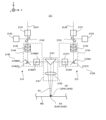
- FIG. 1 is a sectional view showing the configuration of a processing system according to this embodiment.
- FIG. 2 is a block diagram showing the configuration of the processing system of this embodiment.
- FIG. 3 is a perspective view showing the structure of the irradiation optical system.
- FIG. 4(a) is a plan view showing the movement trajectory of the target irradiation area within the processing unit area
- FIG. 4(b) is a plan view showing the movement trajectory of the target irradiation area on the modeling surface.
- FIGS. 5(a) and 5(b) is a plan view showing the movement locus of the target irradiation area within the processing unit area
- FIG. 5(c) is a plan view showing the movement locus of the target irradiation area on the modeling surface.
- FIG. 3 is a plan view showing a movement trajectory.
- FIGS. 6(a) to 6(e) is a cross-sectional view showing a situation in which a certain area on a workpiece is irradiated with processing light and a modeling material is supplied.
- FIG. 7(a) is a plan view showing the target movement trajectory of the processing unit area
- FIG. 7(b) is a plan view showing the target movement trajectory of the processing unit area
- FIG. FIG. 3 is a plan view showing a linear shaped object formed on a surface.
- FIG. 8(a) to 8(c) is a cross-sectional view showing the process of modeling a three-dimensional structure.
- FIG. 9 is a flowchart showing the flow of the molten pool feedback control operation based on the molten pool image.
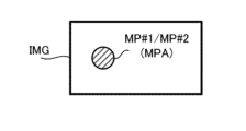
- FIG. 10 shows a molten pool image.
- FIG. 11 shows an added image generated by adding (that is, combining) a plurality of molten pool images.
- FIG. 12 is a timing chart showing the relationship between the size of the molten pool region and the target size.
- FIG. 13 shows a molten pool image in which a molten pool region and a non-molten pool region are reflected.
- FIG. 14 shows multiple molten pool images.
- FIG. 14 shows multiple molten pool images.
- FIG. 15 shows an added image generated by adding (that is, combining) the plurality of molten pool images shown in FIG. 14.
- FIG. 16(a) is a timing chart showing the imaging timing of the imaging unit
- FIG. 16(b) is a timing chart showing the exposure time of the imaging unit
- FIG. 16(c) is the imaging period of the imaging unit. and a timing chart showing the imaging rate.
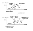
- FIG. 17 shows a histogram of brightness values in the molten pool image when the intensity of the processing light is the first intensity, and a histogram of brightness values in the molten pool image when the intensity of the processing light is the second intensity. .
- FIG. 18 shows a histogram of brightness values in the molten pool image when the intensity of the processing light is the first intensity, and a histogram of brightness values in the molten pool image when the intensity of the processing light is the second intensity.
- FIG. 19 shows a histogram of brightness values in the molten pool image when the speed of movement of the target irradiation area is the first speed, and a histogram of brightness values in the molten pool image when the speed of movement of the target irradiation area is the second speed. The histogram is shown.
- FIG. 20 shows a histogram of brightness values in the molten pool image when the speed of movement of the target irradiation area is the first speed, and a histogram of brightness values in the molten pool image when the speed of movement of the target irradiation area is the second speed.
- the histogram is shown.
- FIG. 21(a) shows a histogram of brightness values in the molten pool image when the intensity of the processing light is the first intensity
- FIG. 21(b) shows the histogram of the brightness values in the molten pool image when the intensity of the processing light is the second intensity and the addition frame
- a histogram of the brightness values in the molten pool image when the number is not changed is shown, and FIG.
- FIG. 21(c) shows the brightness values in the molten pool image when the intensity of the processing light is the second intensity and the number of addition frames is changed.
- the histogram of FIG. 22(a) shows a histogram of brightness values in the molten pool image when the intensity of the processing light is the first intensity
- FIG. 22(b) shows the histogram of the brightness values in the molten pool image when the intensity of the processing light is the second intensity and the addition frame
- FIG. 22(c) shows a histogram of brightness values in the molten pool image when the number is not changed
- FIG. 22(c) shows the brightness values in the molten pool image when the processing light intensity is the second intensity and the number of addition frames is changed.
- the histogram of 23(a) shows a histogram of brightness values in the molten pool image when the speed of movement of the target irradiation area is the first speed
- FIG. 23(b) shows the histogram of the brightness values in the molten pool image when the speed of movement of the target irradiation area is the second
- FIG. 23(c) shows a histogram of brightness values in the molten pool image when the speed is the second speed and the number of added frames is not changed
- FIG. The histogram of brightness values in the molten pool image is shown.
- 24(a) shows a histogram of brightness values in the molten pool image when the speed of movement of the target irradiation area is the first speed
- FIG. 24(b) shows the histogram of the brightness values in the molten pool image when the speed of movement of the target irradiation area is the second
- FIG. 24(c) shows a histogram of brightness values in the molten pool image when the speed is the second speed and the number of added frames is not changed
- FIG. The histogram of brightness values in the molten pool image is shown.
- FIG. 25 is a timing chart showing the relationship between the size of the molten pool region and the target size.
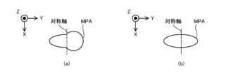
- FIGS. 26(a) and 26(b) shows the shape of the molten pool region.
- FIGS. 27(a) to 27(b) is a cross-sectional view showing a linear object formed when the molten pool region shown in FIG.
- FIG. 26(a) is detected
- FIG. ) to FIG. 27(d) are cross-sectional views showing linear objects formed when the molten pool region shown in FIG. 26(b) is detected.
- FIG. 28(a) shows a movement locus of the molten pool region
- FIG. 28(b) is a cross-section showing a linear model formed when the molten pool region shown in FIG. 28(a) is detected.
- 28(c) shows a movement locus of the molten pool region
- FIG. 28(d) shows a linear shape formed when the molten pool region shown in FIG. 28(c) is detected.
- FIG. 28(e) is a cross-sectional view showing the object
- FIG. 28(e) shows a movement locus of the molten pool region.
- FIG. 29 is a cross-sectional view showing the center position of the molten pool region in the process of stacking a plurality of linear shaped objects.
- a processing apparatus and a processing method will be described using a processing system SYS that can process a workpiece W, which is an example of an object.
- a processing system SYS that performs additional processing based on laser metal deposition (LMD).
- Additional processing based on the laser metallization welding method melts the modeling material M supplied to the workpiece W with processing light EL (that is, an energy beam in the form of light), so that the material M that is integrated with the workpiece W or the workpiece W This is an additive process that creates a model that can be separated from the original.
- processing light EL that is, an energy beam in the form of light
- each of the X-axis direction and the Y-axis direction is a horizontal direction (that is, a predetermined direction within a horizontal plane), and the Z-axis direction is a vertical direction (that is, a direction perpendicular to the horizontal plane). (and substantially in the vertical direction).
- the rotation directions (in other words, the tilt directions) around the X-axis, Y-axis, and Z-axis are referred to as the ⁇ X direction, the ⁇ Y direction, and the ⁇ Z direction, respectively.
- the Z-axis direction may be the direction of gravity.
- the XY plane may be set in the horizontal direction.
- the processing system SYS is capable of performing additional processing on the workpiece W.
- the processing system SYS can form a molded object that is integrated with (or is separable from) the workpiece W by performing additional processing on the workpiece W.
- the additional processing performed on the work W corresponds to processing that adds to the work W a shaped object that is integrated with (or separable from) the work W.
- the modeled object in this embodiment may mean any object modeled by the processing system SYS.
- the processing system SYS uses a three-dimensional structure (that is, a three-dimensional structure that has a size in any three-dimensional direction) as an example of a modeled object. , a structure having dimensions in the Y-axis direction and the Z-axis direction) ST can be modeled.
- the processing system SYS can perform additional processing on the stage 31.
- the work W is a placed object, which is an object placed on the stage 31, the processing system SYS can perform additional processing on the placed object.
- the object placed on the stage 31 may be another three-dimensional structure ST (that is, an existing structure) modeled by the processing system SYS.
- FIG. 1 shows an example in which the workpiece W is an existing structure placed on a stage 31. Further, the explanation will be continued below using an example in which the workpiece W is an existing structure placed on the stage 31.
- the workpiece W may be an item that requires repair and has a defective part.
- the processing system SYS may perform repair processing to repair the item requiring repair by performing additional processing to form a modeled object to compensate for the missing portion. That is, the additional processing performed by the processing system SYS may include additional processing that adds a shaped object to the workpiece W to compensate for a missing portion.
- the processing system SYS is capable of performing additional processing based on the laser overlay welding method.
- the processing system SYS can be said to be a 3D printer that processes objects using layered processing technology.
- the layered processing technology may also be referred to as rapid prototyping, rapid manufacturing, or additive manufacturing.
- the laser deposition welding method may also be referred to as DED (Directed Energy Deposition).
- the processing system SYS using the layered processing technique forms a three-dimensional structure ST in which the plurality of structural layers SL are stacked by sequentially forming a plurality of structural layers SL (see FIG. 7 described later).
- the processing system SYS first sets the surface of the workpiece W as a modeling surface MS for actually modeling the object, and models the first structural layer SL on the modeling surface MS.
- the processing system SYS sets the surface of the first structural layer SL as a new modeling surface MS, and models the second structural layer SL on the new modeling surface MS.
- the processing system SYS repeats the same operation to form a three-dimensional structure ST in which a plurality of structural layers SL are stacked.
- processing unit 2 may also be referred to as a processing device.
- An apparatus including at least one of the material supply source 1, the stage unit 3, the light source 4, and the gas supply source 5 and the processing unit 2 may be referred to as a processing apparatus.
- the control unit 7 may also be referred to as a control device.
- the imaging unit 8 may be referred to as an imaging device.
- a material supply source 1 supplies a modeling material M to a processing unit 2.
- the material supply source 1 supplies a desired amount of modeling material M according to the required amount so that the amount of modeling material M required per unit time to perform additional processing is supplied to the processing unit 2. do.
- processing light EL when it is necessary to distinguish between the two processing lights EL emitted by the irradiation optical system 211, the processing light EL generated by the light source 4#1 may be referred to as “processing light EL” as necessary. #1”, and the processing light EL generated by the light source 4#2 is called “processing light EL#2”.
- the irradiation optical system 211 may change the processing light EL as necessary.
- the target irradiation area EA to which the processing light EL#1 is irradiated is referred to as the "target irradiation area EA#1"
- the target irradiation area EA to which the irradiation optical system 211 irradiates the processing light EL#2 is referred to as the "target irradiation area EA#2”. ”.
- the molten pool MP#1 may not be formed on the modeling surface MS by the irradiation with the processing light EL#1.
- the molten pool MP#2 may not be formed on the modeling surface MS by the irradiation with the processing light EL#2.
- the material may be pumped through the material nozzle 212 .
- the material nozzle 212 supplies the modeling material M together with the transport gas.
- the transport gas for example, purge gas supplied from the gas supply source 5 is used.
- a gas supplied from a gas supply source different from the gas supply source 5 may be used.
- the material nozzle 212 is drawn in a tube shape in FIG. 1, the shape of the material nozzle 212 is not limited to this shape.
- the material nozzle 212 supplies the modeling material M downward (that is, to the -Z side).
- a stage 31 is arranged below the material nozzle 212. When the workpiece W is mounted on the stage 31, the material nozzle 212 supplies the modeling material M toward the modeling surface MS.
- a predetermined angle for example, an acute angle
- the irradiation optical system 211 and the material nozzle 212 may be housed in a head housing 213 included in the processing head 21.
- the head housing 213 is a housing in which a housing space for housing the irradiation optical system 211 and the material nozzle 212 is formed.
- the irradiation optical system 211 and the material nozzle 212 may be housed in a housing space inside the head housing 213.
- the head drive system 22 moves the processing head 21 under the control of the control unit 7. That is, the head drive system 22 moves the irradiation optical system 211 and the material nozzle 212 under the control of the control unit 7.
- the head drive system 22 moves the processing head 21 along at least one of the X-axis direction, the Y-axis direction, the Z-axis direction, the ⁇ X direction, the ⁇ Y direction, and the ⁇ Z direction, for example.
- the operation of moving the processing head 21 along at least one of the ⁇ X direction, ⁇ Y direction, and ⁇ Z direction includes the rotational axis along the X-axis, the Y-axis, and the Z-axis. It may be considered that the operation is equivalent to rotating the processing head 21 around at least one rotation.
- the head drive system 22 moves the processing head 21, the relative positional relationship between the processing head 21 and the stage 31 and the work W placed on the stage 31 changes. As a result, the relative positional relationship between each of the stage 31 and the workpiece W and the irradiation optical system 211 included in the processing head 21 changes. Therefore, the head drive system 22 may be considered to function as a position changing device that can change the relative positional relationship between the stage 31 and the workpiece W, and the irradiation optical system 211. Furthermore, when the relative positional relationship between each of the stage 31 and the workpiece W and the processing head 21 changes, the difference between each of the target irradiation areas EA#1 and EA#2 and the target supply area MA and the workpiece W changes. Relative positions also change.
- the target irradiation areas EA#1 and EA#2 and the target supply area MA are arranged in the X-axis direction and the Y-axis on the surface of the workpiece W (more specifically, the modeling surface MS on which additional processing is performed). direction, the Z-axis direction, the ⁇ X direction, the ⁇ Y direction, and the ⁇ Z direction.
- the head drive system 22 may be considered to be moving the processing head 21 so that each of the target irradiation areas EA#1 and EA#2 and the target supply area MA moves on the modeling surface MS. .
- the stage unit 3 includes a stage 31 and a stage drive system 32.
- the stage drive system 32 moves the stage 31, the relative positional relationship between the processing head 21, the stage 31, and the workpiece W changes. As a result, the relative positional relationship between each of the stage 31 and the workpiece W and the irradiation optical system 211 included in the processing head 21 changes. Therefore, like the head drive system 22, the stage drive system 32 functions as a position change device that can change the relative positional relationship between the stage 31 and the workpiece W, and the irradiation optical system 211. It may be considered as Furthermore, when the relative positional relationship between each of the stage 31 and the workpiece W and the processing head 21 changes, the difference between each of the target irradiation areas EA#1 and EA#2 and the target supply area MA and the workpiece W changes.
- the processing system SYS includes a plurality of light sources 4 (specifically, light sources 4#1 and 4#2).
- the characteristics of the processing light EL#1 emitted by the light source 4#1 and the characteristics of the processing light EL#2 emitted by the light source 4#2 may be the same.
- the wavelength of processing light EL#1 typically, the peak wavelength that is the wavelength at which the intensity is maximum in the wavelength band of processing light EL#1
- the wavelength of processing light EL#2 typically, peak wavelength
- the intensity of processing light EL#1 and the intensity of processing light EL#2 may be different.
- the absorption rate of the workpiece W to the processing light EL#1 and the absorption rate of the workpiece W to the processing light EL#2 may be different.
- the absorption rate of the workpiece W with respect to the peak wavelength of the processing light EL#1 and the absorption rate of the workpiece W with respect to the peak wavelength of the processing light EL#2 may be different.
- the processing system SYS includes a plurality of light sources 4 .
- the processing system SYS does not need to include the plurality of light sources 4.
- the processing system SYS does not need to include a single light source 4.
- the processing system may include, as a single light source 4, a light source that emits (supplies) light in a wide wavelength band or multiple wavelengths.
- the processing system SYS may generate processing light EL#1 and processing light EL#2 having different wavelengths by wavelength-dividing the light emitted from the light source.
- the gas supply source 5 is a purge gas supply source for purging the chamber space 63IN inside the housing 6.
- the purge gas includes an inert gas.
- An example of the inert gas is nitrogen gas or argon gas.
- the gas supply source 5 is connected to the chamber space 63IN via a supply port 62 formed in the partition member 61 of the housing 6 and a supply pipe 51 connecting the gas supply source 5 and the supply port 62.
- the gas supply source 5 supplies purge gas to the chamber space 63IN via the supply pipe 51 and the supply port 62.
- the chamber space 63IN becomes a space purged with the purge gas.
- the purge gas supplied to the chamber space 63IN may be exhausted from an outlet (not shown) formed in the partition member 61.
- the gas supply source 5 may be a cylinder containing an inert gas.
- the gas supply source 5 may be a nitrogen gas generator that generates nitrogen gas using the atmosphere as a raw material.
- the gas supply source 5 supplies the purge gas to the mixing device 12 to which the modeling material M from the material supply source 1 is supplied.
- the gas supply source 5 may be connected to the mixing device 12 via a supply pipe 52 that connects the gas supply source 5 and the mixing device 12.
- the gas supply source 5 supplies purge gas to the mixing device 12 via the supply pipe 52.
- the modeling material M from the material supply source 1 is supplied (specifically, , pumping). That is, the gas supply source 5 may be connected to the material nozzle 212 via the supply pipe 52, the mixing device 12, and the supply pipe 11. In that case, the material nozzle 212 supplies the modeling material M together with the purge gas for pumping the modeling material M.
- the control unit 7 controls the operation of the processing system SYS.
- the control unit 7 may control the processing unit 2 (for example, at least one of the processing head 21 and the head drive system 22) included in the processing system SYS to perform additional processing on the workpiece W.
- the control unit 7 may control the stage unit 3 (for example, the stage drive system 32) included in the processing system SYS so as to perform additional processing on the workpiece W.
- the control unit 7 may control the material supply source 1 included in the processing system SYS so as to perform additional processing on the workpiece W.
- the control unit 7 may control the light source 4 included in the processing system SYS so as to perform additional processing on the workpiece W.
- the control unit 7 may control the gas supply source 5 included in the processing system SYS so as to perform additional processing on the workpiece W.
- the control unit 7 may include, for example, a calculation device 71 and a storage device 72.
- the arithmetic device 71 may include, for example, at least one of a CPU (Central Processing Unit) and a GPU (Graphics Processing Unit).
- Storage device 72 may include, for example, memory.
- the control unit 7 functions as a device that controls the operation of the processing system SYS by the arithmetic device 71 executing a computer program.
- This computer program is a computer program for causing the arithmetic device 71 to perform (that is, execute) the operation to be performed by the control unit 7, which will be described later. That is, this computer program is a computer program for causing the control unit 7 to function so as to cause the processing system SYS to perform the operations described below.
- the computer program executed by the arithmetic device 71 may be recorded in the storage device 72 (that is, a recording medium) included in the control unit 7, or may be stored in any program that is built into the control unit 7 or can be externally attached to the control unit 7. may be recorded on a storage medium (for example, a hard disk or a semiconductor memory). Alternatively, the computing device 71 may download the computer program to be executed from a device external to the control unit 7 via a network interface. Note that the storage device 72 may also be referred to as a recording device.
- the control unit 7 may control the emission mode of the processing light EL by the irradiation optical system 211.
- the injection mode may include, for example, at least one of the intensity of the processing light EL and the emission timing of the processing light EL.
- the emission mode is, for example, the light emission time of the pulsed light, the light emission period of the pulsed light, and the ratio of the length of the light emission time of the pulsed light to the light emission period of the pulsed light. (so-called duty ratio).
- the control unit 7 may control the manner in which the processing head 21 is moved by the head drive system 22.
- the control unit 7 may control the manner in which the stage 31 is moved by the stage drive system 32.
- the movement mode may include, for example, at least one of a movement amount, a movement speed, a movement direction, and a movement timing (movement timing). Furthermore, the control unit 7 may control the manner in which the modeling material M is supplied by the material nozzle 212.
- the supply mode may include, for example, at least one of the supply amount (particularly the supply amount per unit time) and the supply timing (supply timing).
- the control unit 7 does not need to be provided inside the processing system SYS.
- the control unit 7 may be provided as a server or the like outside the processing system SYS.
- the control unit 7 and the processing system SYS may be connected via a wired and/or wireless network (or a data bus and/or a communication line).
- a wired network for example, a network using a serial bus type interface represented by at least one of IEEE1394, RS-232x, RS-422, RS-423, RS-485, and USB may be used.
- a network using a parallel bus interface may be used.
- a network using an interface compliant with Ethernet typified by at least one of 10BASE-T, 100BASE-TX, and 1000BASE-T may be used.
- a network using radio waves may be used.
- An example of a network using radio waves is a network compliant with IEEE802.1x (for example, at least one of a wireless LAN and Bluetooth (registered trademark)).
- a network using infrared rays may be used.
- a network using optical communication may be used as the wireless network.
- the control unit 7 and the processing system SYS may be configured to be able to transmit and receive various information via a network.
- control unit 7 may be able to transmit information such as commands and control parameters to the processing system SYS via a network.
- the processing system SYS may include a receiving device that receives information such as commands and control parameters from the control unit 7 via the network.
- the processing system SYS may include a transmitter that transmits information such as commands and control parameters to the control unit 7 via the network (that is, an output device that outputs information to the control unit 7). good.
- a first control device that performs some of the processes performed by the control unit 7 is provided inside the processing system SYS, while a second control device that performs other parts of the processes performed by the control unit 7 is provided inside the processing system SYS.
- the control device may be provided outside the processing system SYS.
- an arithmetic model that can be constructed by machine learning may be implemented by the arithmetic device 71 executing a computer program.
- An example of a calculation model that can be constructed by machine learning is a calculation model that includes a neural network (so-called artificial intelligence (AI)).
- learning the computational model may include learning parameters (eg, at least one of weights and biases) of the neural network.
- the control unit 7 may control the operation of the processing system SYS using the calculation model. That is, the operation of controlling the operation of the processing system SYS may include the operation of controlling the operation of the processing system SYS using a calculation model.
- the control unit 7 may be equipped with an arithmetic model that has been constructed by offline machine learning using teacher data.
- the recording medium for recording the computer program executed by the control unit 7 includes CD-ROM, CD-R, CD-RW, flexible disk, MO, DVD-ROM, DVD-RAM, DVD-R, DVD+R, and DVD.
- At least one of optical disks such as RW, DVD+RW and Blu-ray (registered trademark), magnetic media such as magnetic tape, magneto-optical disks, semiconductor memories such as USB memory, and any other arbitrary medium capable of storing programs is used. It's okay to be hit.
- the recording medium may include a device capable of recording a computer program (for example, a general-purpose device or a dedicated device in which a computer program is implemented in an executable state in the form of at least one of software and firmware).
- each process or function included in the computer program may be realized by a logical processing block that is realized within the control unit 7 when the control unit 7 (that is, the computer) executes the computer program, or
- the control unit 7 may be realized by hardware such as a predetermined gate array (FPGA (Field Programmable Gate Array), ASIC (Application Specific Integrated Circuit), etc., or may be realized by a combination of logical processing blocks and hardware. Some elements of clothing It may also be realized in a mixed format with partial hardware modules that realize it.
- the imaging unit 8 is an imaging device that can image an object to be imaged under the control of the control unit 7.
- the imaging unit 8 may include a camera capable of imaging the object to be imaged.
- the camera may include an image sensor.
- the image sensor may include a CCD (Charged Coupled Device) sensor.
- the image sensor may include a complementary metal oxide semiconductor (CMOS) sensor.
- CMOS complementary metal oxide semiconductor
- the imaging unit 8 may image the object to be imaged by receiving light from the object to be imaged by the image sensor. That is, the imaging unit 8 may image the object to be imaged by exposing the image sensor to light from the object to be imaged.
- Exposure of the image sensor using light from the object to be imaged may also be referred to as "exposure by the image sensor (that is, by the imaging unit 8) (exposure of the object to be imaged)".
- the imaging unit 8 may be capable of imaging the molten pool MP. That is, the imaging unit 8 may be able to image the area including the molten pool MP (that is, the area on the modeling surface MS including the molten pool MP).
- the imaging unit 8 images the molten pool MP. That is, in the following description, an example will be described in which the imaging unit 8 images an area including the molten pool MP (that is, an area on the modeling surface MS including the molten pool MP).
- the imaging unit 8 may be installed in the processing head 21.
- the imaging unit 8 may be installed in a head housing 213 of the processing head 21.
- the imaging unit 8 attached to the processing head 21 also moves together with the processing head 21.
- the relative positional relationship between the processing head 21 and the imaging unit 8 is fixed.
- the imaging unit 8 does not need to be attached to the processing head 21.
- the imaging unit 8 may be attached to an object different from the processing head 21.
- the imaging unit 8 generates an image in which the imaging target is reflected by imaging the imaging target.
- the imaging unit 8 since the imaging unit 8 images the molten pool MP as described above, the imaging unit 8 generates an image in which the molten pool MP is reflected.
- the image generated by the imaging unit 8 (that is, the image in which the molten pool MP is reflected) will be referred to as a "molten pool image IMG.”
- control unit 7 may control the light source 4 to perform additional processing on the workpiece W based on the molten pool image IMG.
- control unit 7 may control the gas supply source 5 to perform additional processing on the workpiece W based on the molten pool image IMG.
- FIG. 3 is a cross-sectional view showing the structure of the irradiation optical system 211.
- the irradiation optical system 211 includes a first optical system 214, a second optical system 215, and a third optical system 216.
- the first optical system 214 is an optical system into which the processing light EL#1 emitted from the light source 4#1 enters.
- the first optical system 214 is an optical system that emits processing light EL#1 emitted from the light source 4#1 toward the third optical system 216.
- the second optical system 215 is an optical system into which the processing light EL#2 emitted from the light source 4#2 enters.
- the second optical system 215 is an optical system that emits processing light EL#2 emitted from the light source 4#2 toward the third optical system 216.
- the first optical system 214 includes a collimator lens 2141, a parallel plate 2142, a power meter 2143, and a galvano scanner 2144.
- the galvano scanner 2144 includes a focus control optical system 2145 and a galvanometer mirror 2146.
- the first optical system 214 does not need to include at least one of the collimator lens 2141, the parallel plate 2142, the power meter 2143, and the galvano scanner 2144.
- the galvano scanner 2144 does not need to include at least one of the focus control optical system 2145 and the galvanometer mirror 2146.
- the processing light EL#1 that has passed through the parallel plate 2142 is incident on the galvano scanner 2144. Specifically, the processing light EL#1 that has passed through the parallel plate 2142 is incident on the focus control optical system 2145 of the galvano scanner 2144.
- the focus control optical system 2145 is an optical member that can change the focusing position CP of the processing light EL#1 (hereinafter referred to as "focusing position CP#1"). Specifically, the focus control optical system 2145 can change the focusing position CP#1 of the processing light EL#1 along the irradiation direction of the processing light EL#1 irradiated onto the modeling surface MS. In the example shown in FIG. 3, the irradiation direction of the processing light EL#1 irradiated onto the modeling surface MS is a direction in which the Z-axis direction is the main component. In this case, the focus control optical system 2145 can change the focusing position CP#1 of the processing light EL#1 along the Z-axis direction.
- the focus optical system 2145 considers that the focusing position CP#1 of the processing light EL#1 can be changed along the direction of the optical axis AX of the irradiation optical system 211 (typically the third optical system 216). It's okay.
- the focus control optical system 2145 may include, for example, a plurality of lenses arranged along the irradiation direction of the processing light EL#1. In this case, the focus control optical system 2145 moves at least one of the plurality of lenses along its optical axis direction to change the focusing position CP#1 of the processing light EL#1. good.
- the focus control optical system 2145 changes the focusing position CP#1 of the processing light EL#1, the positional relationship between the focusing position CP#1 of the processing light EL#1 and the modeling surface MS changes. In particular, the positional relationship between the focusing position CP#1 of the processing light EL#1 and the modeling surface MS in the irradiation direction of the processing light EL#1 changes. Therefore, the focus control optical system 2145 changes the focus position CP#1 of the processing light EL#1 and the modeling surface MS by changing the focus position CP#1 of the processing light EL#1. It may be considered that the positional relationship between the two is being changed.
- the processing system SYS can adjust the focus position CP#1 of the processing light EL#1 in the irradiation direction of the processing light EL#1 and the The positional relationship with the surface MS can be changed.
- the processing system SYS uses the head drive system 22 to move the processing head 21 along the irradiation direction of the processing light EL#1.
- the positional relationship between the condensing position CP#1 and the modeling surface MS may be changed.
- Processing light EL#1 emitted from the focus control optical system 2145 enters the galvanometer mirror 2146.
- the galvanometer mirror 2146 changes the emission direction of the processing light EL#1 emitted from the galvanometer mirror 2146 by deflecting the processing light EL#1. For this reason, the galvano mirror 2146 may be referred to as a deflection optical system.
- the direction of the processing light EL#1 emitted from the galvanometer mirror 2146 is changed, the position from which the processing light EL#1 is emitted from the processing head 21 is changed.
- the galvanometer mirror 2146 includes, for example, an X-scanning mirror 2146MX, an X-scanning motor 2146AX, a Y-scanning mirror 2146MY, and a Y-scanning motor 2146AY.
- Processing light EL#1 emitted from the focus control optical system 2145 enters the X scanning mirror 2146MX.
- the X-scanning mirror 2146MX reflects the processing light EL#1 that has entered the X-scanning mirror 2146MX toward the Y-scanning mirror 2146MY.
- the Y scanning mirror 2146MY reflects the processing light EL#1 that has entered the Y scanning mirror 2146MY toward the third optical system 216. Note that each of the X scanning mirror 2146MX and the Y scanning mirror 2146MY may be referred to as a galvano mirror.
- the X-scanning motor 2146AX swings or rotates the X-scanning mirror 2146MX around a rotation axis along the Y-axis.
- the angle of the X-scanning mirror 2146MX with respect to the optical path of the processing light EL#1 incident on the X-scanning mirror 2146MX is changed.
- the processing light EL#1 scans the modeling surface MS along the X-axis direction by swinging or rotating the X-scanning mirror 2146MX. That is, the target irradiation area EA#1 (that is, the irradiation position of the processing light EL#1) moves on the modeling surface MS along the X-axis direction.
- the Y scanning motor 2146AY swings or rotates the Y scanning mirror 2146MY around a rotation axis along the X axis.
- the angle of the Y scanning mirror 2146MY with respect to the optical path of the processing light EL#1 incident on the Y scanning mirror 2146MY is changed.
- the processing light EL#1 scans the modeling surface MS along the Y-axis direction by swinging or rotating the Y-scanning mirror 2146MY. That is, the target irradiation area EA#1 (that is, the irradiation position of the processing light EL#1) moves on the modeling surface MS along the Y-axis direction.
- the virtual area in which the galvano mirror 2146 moves the target irradiation area EA#1 on the modeling surface MS is referred to as a processing unit area BSA (particularly processing unit area BSA#1).
- the target irradiation area EA#1 may be considered to move on a surface of the modeling surface MS that overlaps with the processing unit area BSA#1.
- the galvanometer mirror 2146 moves the target irradiation area EA#1 on the printing surface MS while the positional relationship between the irradiation optical system 211 and the printing surface MS is fixed (that is, without changing).
- This area is referred to as a processing unit area BSA (particularly, processing unit area BSA#1).
- the target irradiation area EA#1 moves on the modeling surface MS.
- the relative positional relationship between galvanometer mirror 2146 and modeling surface MS changes.
- the processing unit area BSA#1 determined based on the processing head 21 that is, the processing unit area BSA#1 in which the galvanometer mirror 2146 moves the target irradiation area EA#1 on the printing surface MS
- the operation of moving at least one of the processing head 21 and the stage 31 may be considered to be equivalent to the operation of moving the processing unit area BSA#1 with respect to the modeling surface MS.
- FIGS. As another example of the operation of moving the molten pool MP#1 within the processing unit area BSA#1, as shown in FIGS. is stationary (that is, not moving) on the printing surface MS, and within the processing unit area BSA#1, the target irradiation area EA#1 is located at multiple points along the printing surface MS. Processing light EL#1 may be deflected so as to move along the scanning direction. In other words, the galvanometer mirror 2146 deflects the processing light EL#1 so that the target irradiation area EA#1 moves along a plurality of scanning directions within a coordinate system determined based on the processing unit area BSA#1. Good too.
- the target irradiation area EA#1 is moved in the X-axis direction and in the X-axis direction within the processing unit area BSA#1 so that the movement locus of the target irradiation area EA#1 within the processing unit area BSA#1 is circular.
- An example of reciprocating movement along each of the Y-axis directions is shown.
- the shape of the processing unit area BSA#1 to which the target irradiation area EA#1 moves may be circular.
- the target irradiation area EA#1 within the processing unit area BSA#1 is An example of reciprocating movement along each of the axial direction and the Y-axis direction is shown.
- the shape of the processing unit area BSA#1 to which the target irradiation area EA#1 moves may be rectangular.
- the operation of periodically moving the target irradiation area EA#1 on the modeling surface MS as shown in FIGS. 4(a), 5(a), and 5(b) is referred to as a wobbling operation.
- the operation of periodically moving (in other words, deflecting) the processing light EL#1 so that the target irradiation area EA#1 periodically moves on the modeling surface MS may be referred to as a wobbling operation.
- the control unit 7 controls the processing unit area BSA#1 to move on the modeling surface MS while the target irradiation area EA#1 is being moved within the processing unit area BSA#1 using the galvanometer mirror 2146. , at least one of the processing head 21 and the stage 31 may be moved. In other words, the control unit 7 controls the processing unit area BSA#1 to move on the modeling surface MS during the period in which the target irradiation area EA#1 is moved within the processing unit area BSA#1 using the galvanometer mirror 2146. Thus, at least one of the head drive system 22 and the stage drive system 32 may be controlled.
- FIG. 5(c) shows the target irradiation area EA on the modeling surface MS when the processing unit area BSA#1 shown in FIG. 5(a) moves on the modeling surface MS along the target movement trajectory MT0. #1 movement trajectory MT#1 is shown.
- a molten pool MP#1 is formed in at least a part of the processing unit area BSA#1.
- a modeled object is modeled within the processing unit area BSA#1.
- the machining unit area BSA#1 is arranged in a direction intersecting the movement direction of the machining unit area BSA#1 on the modeling surface MS (specifically, the direction in which the target movement trajectory MT0 extends). This is an area with a width.
- a modeled object having a width along the direction intersecting the target movement trajectory MT0 of the processing unit area BSA#1 is modeled on the modeling surface MS.
- a shaped object is formed that has a width along the X-axis direction and extends along the Y-axis direction.
- a shaped object is formed that has a width along the X-axis direction and extends along the Y-axis direction.
- the processing unit area BSA#1 is scanned by the processing light EL#1 by the galvanometer mirror 2146. Therefore, the amount of energy transmitted from the processing light EL#1 to the processing unit area BSA#1 is greater than when the processing light EL#1 is irradiated onto the modeling surface MS without using the galvano mirror 2146.
- the possibility of variation within the processing unit area BSA#1 is reduced. That is, it is possible to equalize the distribution of the amount of energy transmitted from the processing light EL#1 to the processing unit area BSA#1.
- the processing system SYS is able to model the object on the modeling surface MS with relatively high modeling accuracy.
- the processing system SYS does not need to irradiate the modeling surface MS with the processing light EL#1 in units of processing unit areas BSA#1.
- the processing system SYS may irradiate the modeling surface MS with the processing light EL#1 without using the galvanometer mirror 2146.
- the target irradiation area EA#1 may move on the modeling surface MS as at least one of the processing head 21 and the stage 31 moves.
- the processing light EL#1 reflected by the parallel plate 2142 is incident on the power meter 2143.
- the power meter 2143 can detect the intensity of the processing light EL#1 that is incident on the power meter 2143.
- the power meter 2143 may include a light receiving element that detects the processing light EL#1 as light.
- the power meter 2143 may detect the intensity of the processing light EL#1 by detecting the processing light EL#1 as heat.
- the power meter 2143 may include a heat detection element that detects the heat of the processing light EL#1.
- the power meter 2143 can stably detect the intensity of the processing light EL#1 without being affected by the deflection of the processing light EL#1 by the galvanometer mirror 2146.
- the arrangement position of the power meter 2143 is not limited to the example shown in FIG. 3.
- the power meter 2143 may detect the intensity of the processing light EL#1 traveling on the optical path between the galvanometer mirror 2146 and the modeling surface MS.
- the power meter 2143 may detect the intensity of the processing light EL#1 traveling along the optical path within the galvanometer mirror 2146.
- the detection result of the power meter 2143 is output to the control unit 7.
- the control unit 7 may control (in other words, change) the intensity of the processing light EL#1 based on the detection result of the power meter 2143 (that is, the detection result of the intensity of the processing light EL#1).
- the control unit 7 may control the intensity of the processing light EL#1 so that the intensity of the processing light EL#1 on the modeling surface MS becomes a desired intensity.
- the control unit 7 changes the intensity of the processing light EL#1 emitted from the light source 4#1 based on the detection result of the power meter 2143.
- the light source 4#1 may be controlled.
- the processing system SYS can appropriately model the object on the modeling surface MS by irradiating the processing light EL#1 having an appropriate intensity onto the modeling surface MS.
- the first optical system 214 controls the processing light EL#1 that is incident on the power meter 2143 so that the processing light EL#1 having an intensity that is not high enough to damage the power meter 2143 is incident on the power meter 2143.
- the strength may be weakened.
- the reflectance of the parallel plate 2142 for the processing light EL#1 may be set to an appropriate value. Specifically, the lower the reflectance of the parallel plate 2142 for the processing light EL#1, the lower the intensity of the processing light EL#1 that enters the power meter 2143. Therefore, the reflectance of the parallel plate 2142 is set to a value low enough to allow processing light EL#1 having an intensity that is not high enough to damage the power meter 2143 to enter the power meter 2143. May be set.
- the reflectance of the parallel plate 2142 may be less than 10%.
- the reflectance of the parallel plate 2142 may be less than a few percent. Raw glass may be used as the parallel flat plate 2142 with low reflectance.
- the first optical system 214 may cause the processed light EL#1 to enter the power meter 2143 via a plurality of parallel plates 2142. good. Specifically, the processing light EL#1 that has been reflected multiple times by each of the parallel flat plates 2142 may be incident on the power meter 2143. In this case, the intensity of the processing light EL#1 reflected multiple times by the plurality of parallel flat plates 2142 is weaker than the intensity of the processing light EL#1 reflected once by one parallel plate 2142. Therefore, there is a high possibility that the processing light EL#1 having an intensity that is not high enough to damage the power meter 2143 will be incident on the power meter 2143.
- the surface of the parallel plate 2142 (particularly at least one of the incident surface on which the processing light EL#1 is incident and the reflective surface on which the processing light EL#1 is reflected) may be subjected to a desired coating treatment.
- the surface of the parallel plate 2142 may be subjected to anti-reflection coating treatment (AR).
- AR anti-reflection coating treatment
- the second optical system 215 includes a collimator lens 2151, a parallel plate 2152, a power meter 2153, and a galvano scanner 2154.
- the galvano scanner 2154 includes a focus control optical system 2155 and a galvanometer mirror 2156.
- the second optical system 215 does not need to include at least one of the collimator lens 2151, the parallel plate 2152, the power meter 2153, and the galvano scanner 2154.
- the galvano scanner 2154 does not need to include at least one of the focus control optical system 2155 and the galvanometer mirror 2156.
- the processing light EL#2 that has passed through the parallel plate 2152 is incident on the galvano scanner 2154. Specifically, the processing light EL#2 that has passed through the parallel plate 2152 is incident on the focus control optical system 2155 of the galvano scanner 2154.
- the focus control optical system 2155 is an optical member that can change the focusing position CP of the processing light EL#2 (hereinafter referred to as "focusing position CP#2"). Specifically, the focus control optical system 2155 can change the focusing position CP#2 of the processing light EL#2 along the irradiation direction of the processing light EL#2 that is irradiated onto the modeling surface MS. In the example shown in FIG. 3, the irradiation direction of the processing light EL#2 irradiated onto the modeling surface MS is a direction in which the Z-axis direction is the main component. In this case, the focus control optical system 2155 can change the focusing position CP#2 of the processing light EL#2 along the Z-axis direction.
- the focus control optical system 2155 can change the focusing position CP#2 of the processing light EL#2 along the direction intersecting the modeling surface MS (for example, the surface of the workpiece W or the structural layer SL).
- the focus optical system 2155 considers that the focusing position CP#2 of the processing light EL#2 can be changed along the direction of the optical axis AX of the irradiation optical system 211 (typically the third optical system 216). It's okay.
- the irradiation direction of the processing light EL#2 may mean the irradiation direction of the processing light EL#2 emitted from the third optical system 216.
- the irradiation direction of the processing light EL#2 may be the same as the direction along the optical axis of the third optical system 216.
- the irradiation direction of the processing light EL#2 may be the same as the direction along the optical axis of the final optical member disposed closest to the modeling surface MS among the optical members constituting the third optical system 216.
- the final optical member may be an f ⁇ lens 2162, which will be described later.
- the final optical member may be the optical member disposed closest to the modeling surface MS among the plurality of optical members configuring the f ⁇ lens 2162. good.
- the focus control optical system 2155 may include, for example, a plurality of lenses arranged along the irradiation direction of the processing light EL#2. In this case, the focus control optical system 2155 may change the focusing position CP of the processing light EL#2 by moving at least one of the plurality of lenses along its optical axis direction.
- the focus control optical system 2155 changes the focusing position CP#2 of the processing light EL#2, the positional relationship between the focusing position CP#2 of the processing light EL#2 and the modeling surface MS changes. In particular, the positional relationship between the focusing position CP#2 of the processing light EL#2 and the modeling surface MS in the irradiation direction of the processing light EL#2 changes. Therefore, the focus control optical system 2155 changes the focus position CP#2 of the processing light EL#2 and the modeling surface MS by changing the focus position CP#2 of the processing light EL#2. It may be considered that the positional relationship between the
- the galvano scanner 2154 does not need to include the focus control optical system 2155. Even in this case, if the positional relationship between the irradiation optical system 211 and the modeling surface MS in the irradiation direction of the processing light EL#2 changes, the condensing position of the processing light EL#2 in the irradiation direction of the processing light EL#2 The positional relationship between CP#2 and the modeling surface MS changes.
- the processing system SYS can adjust the focus position CP#2 of the processing light EL#2 in the irradiation direction of the processing light EL#2 and the The positional relationship with the surface MS can be changed.
- the processing system SYS uses the head drive system 22 to move the processing head 21 along the irradiation direction of the processing light EL#2, thereby increasing the processing light EL#2 in the irradiation direction of the processing light EL#2.
- the positional relationship between the condensing position CP#2 and the modeling surface MS may be changed.
- the processing system SYS uses the stage drive system 32 to move the stage 31 along the irradiation direction of the processing light EL#2, thereby concentrating the processing light EL#2 in the irradiation direction of the processing light EL#2.
- the positional relationship between optical position CP#2 and modeling surface MS may be changed.
- the galvano mirror 2156 changes the emission direction of the processing light EL#2 emitted from the galvano mirror 2156 by deflecting the processing light EL#2. For this reason, the galvanometer mirror 2156 may be referred to as a deflection optical system.
- the direction of the processing light EL#2 emitted from the galvanometer mirror 2156 is changed, the position from which the processing light EL#2 is emitted from the processing head 21 is changed.
- the galvano mirror 2156 may be considered to function as an irradiation position moving device that can move the irradiation position of the processing light EL#2 on the modeling surface MS.
- the galvanometer mirror 2156 may be considered to function as a position changing device that can change the irradiation position of the processing light EL#2 with respect to the processing head 21.
- the galvanometer mirror 2156 includes, for example, an X-scanning mirror 2156MX, an X-scanning motor 2156AX, a Y-scanning mirror 2156MY, and a Y-scanning motor 2156AY.
- Processing light EL#2 emitted from the focus control optical system 2155 enters the X scanning mirror 2156MX.
- the X-scanning mirror 2156MX reflects the processing light EL#2 that has entered the X-scanning mirror 2156MX toward the Y-scanning mirror 2156MY.
- the Y scanning mirror 2156MY reflects the processing light EL#2 that has entered the Y scanning mirror 2156MY toward the third optical system 216. Note that each of the X scanning mirror 2156MX and the Y scanning mirror 2156MY may be referred to as a galvano mirror.
- the X-scanning motor 2156AX swings or rotates the X-scanning mirror 2156MX around a rotation axis along the Y-axis.
- the angle of the X-scanning mirror 2156MX with respect to the optical path of the processing light EL#2 incident on the X-scanning mirror 2156MX is changed.
- the processing light EL#2 scans the modeling surface MS along the X-axis direction by swinging or rotating the X-scanning mirror 2156MX. That is, the target irradiation area EA#2 (that is, the irradiation position of the processing light EL#2) moves on the modeling surface MS along the X-axis direction.
- the Y scan motor 2156AY swings or rotates the Y scan mirror 2156MY around a rotation axis along the X axis.
- the angle of the Y scanning mirror 2156MY with respect to the optical path of the processing light EL#2 incident on the Y scanning mirror 2156MY is changed.
- the processing light EL#2 scans the modeling surface MS along the Y-axis direction by swinging or rotating the Y-scanning mirror 2156MY. That is, the target irradiation area EA#2 (that is, the irradiation position of the processing light EL#2) moves on the modeling surface MS along the Y-axis direction.
- the virtual area in which the galvano mirror 2156 moves the target irradiation area EA#2 on the modeling surface MS is referred to as a processing unit area BSA (particularly processing unit area BSA#2).
- the target irradiation area EA#2 may be considered to move on the surface (first surface) of the modeling surface MS that overlaps with the processing unit area BSA#2.
- the galvanometer mirror 2156 moves the target irradiation area EA#2 on the printing surface MS while the positional relationship between the irradiation optical system 211 and the printing surface MS is fixed (that is, without changing).
- This area is referred to as a processing unit area BSA (particularly, processing unit area BSA#2).
- the processing unit area BSA#2 is a virtual area where the processing head 21 actually performs additional processing using the processing light EL#2 while the positional relationship between the irradiation optical system 211 and the modeling surface MS is fixed (in other words, , range).
- the processing unit area BSA#2 is a virtual area (in other words, a range) that the processing head 21 actually scans with the processing light EL#2 while the positional relationship between the irradiation optical system 211 and the modeling surface MS is fixed. show.
- the processing unit area BSA#2 indicates an area (in other words, a range) in which the target irradiation area EA#2 actually moves while the positional relationship between the irradiation optical system 211 and the modeling surface MS is fixed.
- the processing unit area BSA#2 may be considered to be a virtual area determined based on the processing head 21 (in particular, the irradiation optical system 211). That is, the processing unit area BSA#2 may be considered to be a virtual area located on the modeling surface MS at a position determined based on the processing head 21 (in particular, the irradiation optical system 211). Note that the maximum area in which the galvanometer mirror 2146 can move the target irradiation area EA#2 on the printing surface MS with the positional relationship between the irradiation optical system 211 and the printing surface MS fixed is defined as the processing unit area BSA#. It may be called 2.
- the processing system SYS can use the galvanometer mirror 2156 to move the target irradiation area EA#2 within the processing unit area BSA#2. Therefore, the operation of deflecting the processing light EL#2 using the galvano mirror 2156 may be considered to be equivalent to the operation of moving the target irradiation area EA#2 within the processing unit area BSA#2. Furthermore, as described above, the molten pool MP#2 is formed by irradiating the target irradiation area EA#2 with the processing light EL#2. In this case, the processing system SYS may be considered to be moving the molten pool MP#2 within the processing unit area BSA#2 using the galvanometer mirror 2156.
- the operation of deflecting the processing light EL#2 using the galvanometer mirror 2156 may be considered to be equivalent to the operation of moving the molten pool MP#2 within the processing unit area BSA#2. That is, the operation of moving the target irradiation area EA#2 within the processing unit area BSA#2 may be considered to be equivalent to the operation of moving the molten pool MP#2 within the processing unit area BSA#2.
- the target irradiation area EA#2 moves on the modeling surface MS.
- the relative positional relationship between galvanometer mirror 2146 and modeling surface MS changes.
- the processing unit area BSA#2 determined based on the processing head 21 that is, the processing unit area BSA#2 in which the galvanometer mirror 2156 moves the target irradiation area EA#2 on the printing surface MS
- the operation of moving at least one of the processing head 21 and the stage 31 may be considered to be equivalent to the operation of moving the processing unit area BSA#2 with respect to the modeling surface MS.
- the characteristics of the processing unit area BSA#2 may be the same as the characteristics of the processing unit area BSA#1 described above.
- the manner of movement of the target irradiation area EA#2 within the processing unit area BSA#2 is the same as the movement manner of the target irradiation area EA#1 within the processing unit area BSA#1 described above. There may be. Therefore, a detailed explanation of the characteristics of the processing unit area BSA#2 and the movement mode (for example, movement trajectory, etc.) of the target irradiation area EA#2 within the processing unit area BSA#2 will be omitted, but an example thereof is provided below. Let's briefly explain.
- the galvano mirror 2156 controls the processing unit area BSA #2 under the assumption that the processing unit area BSA #2 is stationary (that is, not moving) on the modeling surface MS.
- the processing light EL#2 may be deflected so that the target irradiation area EA#2 moves along a single scanning direction along the modeling surface MS.
- the galvanometer mirror 2156 operates under the assumption that the processing unit area BSA#2 is stationary (that is, not moving) on the modeling surface MS.
- the processing light EL#2 may be deflected so that the target irradiation area EA#2 moves along a plurality of scanning directions within the processing unit area BSA#2.
- the operation of periodically moving the target irradiation area EA#2 on the modeling surface MS as shown in FIGS. 4(a), 5(a), and 5(b) is referred to as a wobbling operation.
- the operation of periodically moving (in other words, deflecting) the processing light EL#2 so as to periodically move the target irradiation area EA#2 on the modeling surface MS may be referred to as a wobbling operation. .
- the processing unit area BSA#1 and the processing unit area BSA#2 match. That is, the processing unit area BSA#1 is the same as the processing unit area BSA#2. Therefore, the galvanometer mirror 2156 may be considered to deflect the processing light EL#2 so that the target irradiation area EA#2 moves within the processing unit area BSA#1.
- the galvanometer mirror 2146 may be regarded as deflecting the processing light EL#1 so that the target irradiation area EA#1 moves within the processing unit area BSA#2.
- the processing unit area BSA#1 and the processing unit area BSA#2 may be partially different.
- a molten pool MP#2 is formed in at least a part of the processing unit area BSA#2.
- a modeled object is modeled within the processing unit area BSA#2.
- the machining unit area BSA#2 is arranged in a direction intersecting the movement direction of the machining unit area BSA#2 on the modeling surface MS (specifically, the direction in which the target movement trajectory MT0 extends). This is an area with a width.
- a modeled object having a width along the direction intersecting the target movement trajectory MT0 of the processing unit area BSA#2 is modeled on the modeling surface MS.
- a shaped object is formed that has a width along the X-axis direction and extends along the Y-axis direction.
- a shaped object is formed that has a width along the X-axis direction and extends along the Y-axis direction.
- the processing unit area BSA#2 is scanned by the processing light EL#2 by the galvanometer mirror 2156. Therefore, the amount of energy transmitted from the processing light EL#2 to the processing unit area BSA#2 is greater than when the processing light EL#2 is irradiated onto the modeling surface MS without using the galvanometer mirror 2156.
- the possibility of variation within the processing unit area BSA#2 is reduced. That is, it is possible to equalize the amount of energy transmitted from the processing light EL#2 to the processing unit area BSA#2.
- the processing system SYS is able to model the object on the modeling surface MS with relatively high modeling accuracy.
- the processing system SYS does not need to irradiate the modeling surface MS with the processing light EL#2 in units of processing unit areas BSA#2.
- the processing system SYS may irradiate the modeling surface MS with the processing light EL#2 without using the galvanometer mirror 2156.
- the target irradiation area EA#2 may move on the modeling surface MS as at least one of the processing head 21 and the stage 31 moves.
- Power meter 2153 is a specific example of an electrical component used to control processing light EL#2.
- the power meter 2153 can detect the intensity of the processing light EL#2 that is incident on the power meter 2153.
- the power meter 2153 may include a light receiving element that detects the processing light EL#2 as light.
- the power meter 2153 may detect the intensity of the processing light EL#2 by detecting the processing light EL#2 as heat.
- the power meter 2153 may include a heat detection element that detects the heat of the processing light EL#2.
- the power meter 2153 detects the intensity of the processing light EL#2 reflected by the parallel plate 2152. Since the parallel plate 2152 is placed on the optical path of the processing light EL#2 between the light source 4#2 and the galvano mirror 2156, the power meter 2153 is arranged on the optical path of the processing light EL#2 between the light source 4#2 and the galvano mirror 2156. It may be considered that the intensity of the processing light EL#2 traveling is detected.
- the power meter 2153 can stably detect the intensity of the processing light EL#2 without being affected by the deflection of the processing light EL#2 by the galvanometer mirror 2156.
- the arrangement position of the power meter 2153 is not limited to the example shown in FIG. 3.
- the power meter 2153 may detect the intensity of the processing light EL#2 traveling on the optical path between the galvanometer mirror 2156 and the modeling surface MS.
- the power meter 2153 may detect the intensity of the processing light EL#2 traveling along the optical path within the galvanometer mirror 2156.
- the detection result of the power meter 2153 is output to the control unit 7.
- the control unit 7 may control (in other words, change) the intensity of the processing light EL#2 based on the detection result of the power meter 2153 (that is, the detection result of the intensity of the processing light EL#2).
- the control unit 7 may control the intensity of the processing light EL#2 so that the intensity of the processing light EL#2 on the modeling surface MS becomes a desired intensity.
- the control unit 7 changes the intensity of the processing light EL#2 emitted from the light source 4#2 based on the detection result of the power meter 2153.
- the light source 4#2 may be controlled.
- the processing system SYS can appropriately model a model on the model surface MS by irradiating the model surface MS with the processing light EL#2 having an appropriate intensity.
- the processing light EL#2 has an intensity capable of melting the modeling material M. Therefore, the processing light EL#2 incident on the power meter 2153 may have an intensity capable of melting the modeling material M. However, if the processing light EL#2 having an intensity capable of melting the modeling material M enters the power meter 2153, the power meter 2153 may be damaged by the processing light EL#2. Therefore, processing light EL#2 having an intensity that is not high enough to damage the power meter 2153 may be incident on the power meter 2153.
- the reflectance of the parallel plate 2152 with respect to the processing light EL#2 may be set to an appropriate value. Specifically, the lower the reflectance of the parallel plate 2152 for the processing light EL#2, the lower the intensity of the processing light EL#2 that enters the power meter 2153. Therefore, the reflectance of the parallel plate 2152 is set to a value low enough to allow processing light EL#2 having an intensity that is not high enough to damage the power meter 2153 to enter the power meter 2153. May be set.
- the reflectance of the parallel plate 2152 may be less than 10%.
- the reflectance of the parallel plate 2152 may be less than a few percent. Raw glass may be used as the parallel flat plate 2152 with low reflectance.
- the second optical system 215 may cause the processed light EL#2 to enter the power meter 2153 via a plurality of parallel plates 2152. good. Specifically, the processing light EL#2 reflected multiple times by the parallel flat plates 2152 may enter the power meter 2153. In this case, the intensity of the processing light EL#2 reflected multiple times by the plurality of parallel flat plates 2152 is weaker than the intensity of the processing light EL#2 reflected once by the single parallel plate 2152. Therefore, there is a high possibility that the processing light EL#2 having an intensity not high enough to damage the power meter 2153 will be incident on the power meter 2153.
- a desired coating treatment may be applied to the surface of the parallel plate 2152 (particularly at least one of the incident surface on which the processing light EL#2 is incident and the reflective surface on which the processing light EL#2 is reflected).
- the surface of the parallel plate 2152 may be subjected to anti-reflection coating treatment (AR).
- the third optical system 216 includes a prism mirror 2161 and an f ⁇ lens 2162.
- the three-optical system 216 does not need to include the prism mirror 2161.
- the f ⁇ lens 2162 may be an optical element that can condense each of the processing lights EL#1 and EL#2 onto a condensing surface.
- the f ⁇ lens 2162 may be referred to as a condensing optical system.
- the condensing surface of the f ⁇ lens 2162 may be set, for example, on the modeling surface MS.
- the third optical system 216 may be considered to include a condensing optical system with a projection characteristic of f ⁇ .
- the third optical system 216 may include a condensing optical system whose projection characteristics are different from f ⁇ .
- the third optical system 216 may include a condensing optical system with a projection characteristic of f ⁇ tan ⁇ .
- the third optical system 216 may include a condensing optical system with a projection characteristic of f ⁇ sin ⁇ .
- the optical axis AX of the f ⁇ lens 2162 is an axis along the Z-axis. Therefore, the f ⁇ lens 2162 emits each of the processing lights EL#1 and EL#2 along the Z-axis direction.
- the irradiation direction of the processing light EL#1 and the irradiation direction of the processing light EL#2 may be the same direction. Both the irradiation direction of processing light EL#1 and the irradiation direction of processing light EL#2 may be in the Z-axis direction.
- the irradiation direction of the processing light EL#1 and the irradiation direction of the processing light EL#2 may both be directions along the optical axis AX of the f ⁇ lens 2162. However, the irradiation direction of the processing light EL#1 and the irradiation direction of the processing light EL#2 may not be the same direction. The irradiation direction of processing light EL#1 and the irradiation direction of processing light EL#2 may be different directions.
- the additional processing performed on the workpiece W corresponds to an operation of forming a formed object such that a formed object integrated with the workpiece W (or separable from it) is added to the workpiece W.
- additional processing for forming a three-dimensional structure ST which is a modeled object having a desired shape, will be described.
- the processing system SYS forms the three-dimensional structure ST by performing additional processing based on the laser overlay welding method. Therefore, the processing system SYS may model the three-dimensional structure ST by performing existing additional processing based on the laser overlay welding method.
- an example of the operation of modeling the three-dimensional structure ST using the laser overlay welding method will be briefly described.
- the processing system SYS forms a three-dimensional structure ST on the workpiece W based on three-dimensional model data (in other words, three-dimensional model information) of the three-dimensional structure ST to be formed.
- three-dimensional model data measurement data of a three-dimensional object measured by at least one of a measuring device provided within the processing system SYS and a three-dimensional shape measuring machine provided separately from the processing system SYS may be used.
- the processing system SYS sequentially models, for example, a plurality of layered partial structures (hereinafter referred to as "structural layers") SL arranged along the Z-axis direction.
- the processing system SYS sequentially shapes a plurality of structural layers SL one layer at a time based on data on the plurality of layers obtained by cutting the three-dimensional model of the three-dimensional structure ST into rounds along the Z-axis direction. To go.
- a three-dimensional structure ST which is a layered structure in which a plurality of structural layers SL are stacked, is modeled.
- the structural layer SL does not necessarily have to be a shaped object having a layered shape.
- a flow of operations for modeling a three-dimensional structure ST by sequentially modeling a plurality of structural layers SL one by one will be described.
- processing unit areas BSA#1 and BSA#2 are set in desired areas on the modeling surface MS corresponding to the surface of the workpiece W or the surface of the structured layer SL that has been modeled. At least one of the processing head 21 and the stage 31 is moved so that the processing head 21 and the stage 31 are moved. After that, the irradiation optical system 211 irradiates the processing unit areas BSA#1 and BSA#2 with processing lights EL#1 and EL#2, respectively.
- condensing positions CP#1 and CP#2 at which processing lights EL#1#1 and EL#2 are condensed, respectively, in the Z-axis direction may coincide with the modeling surface MS.
- the focusing positions CP#1 and CP#2 at which the processing lights EL#1#1 and EL#2 are focused, respectively, in the Z-axis direction may be located outside the modeling surface MS.
- molten pools MP#1 and MP#2 are formed on the modeling surface MS irradiated with the processing beams EL#1 and EL#2, respectively. Further, as shown in FIG.
- the processing system SYS supplies the modeling material M from the material nozzle 212 under the control of the control unit 7.
- the modeling material M is supplied to each of the molten pools MP#1 and MP#2.
- the modeling material M supplied to the molten pool MP#1 is melted by the processing light EL#1 that is irradiated to the molten pool MP#1.
- the modeling material M supplied to the molten pool MP#2 is melted by the processing light EL#2 that is irradiated to the molten pool MP#2.
- the irradiation optical system 211 uses galvano mirrors 2146 and 2156 to move target irradiation areas EA#1 and EA#2 within processing unit areas BSA#1 and BSA#2, respectively. That is, the irradiation optical system 211 scans the processing unit areas BSA#1 and BSA#2 with the processing light beams EL#1 and EL#2, respectively, using the galvanometer mirrors 2146 and 2156, respectively.
- the processing light EL#1 is no longer irradiated to the molten pool MP#1 due to the movement of the target irradiation area EA#1
- the modeling material M melted in the molten pool MP#1 is cooled and solidified (that is, solidified). do.
- the processing light EL#2 stops irradiating the molten pool MP#2 with the movement of the target irradiation area EA#2 with the movement of the target irradiation area EA#2, the modeling material M melted in the molten pool MP#2 is cooled and solidified (i.e. , coagulation). Furthermore, as the target irradiation areas EA#1 and EA#2 move, the molten pools MP#1 and MP#2 also move. As a result, as shown in FIG. 6(c), within the processing unit areas BSA#1 and BSA#2 where the molten pools MP#1 and MP#2 move, the modeled object made of the solidified modeling material M is It is deposited on the modeling surface MS.
- a modeled object is composed of a modeling material M solidified in the processing unit area BSA#1
- a modeled object is composed of a modeling material M solidified in the processing unit area BSA#2.
- the model is physically separated from the model.
- the modeled object made of the solidified modeling material M in the processing unit area BSA#1 and the modeled object made of the solidified modeling material M in the processing unit area BSA#2 may be integrated. .
- the processing unit areas BSA#1 and BSA#2 match (or partially overlap)
- the modeling made of the solidified modeling material M within the processing unit area BSA#1 The object and the modeled object made of the model material M solidified within the processing unit area BSA#2 may be integrated.
- the processing system SYS processes the modeling surface MS. At least one of the processing head 21 and the stage 31 may be moved so that the unit areas BSA#1 and BSA#2 are moved.
- the processing system SYS moves the target irradiation areas EA#1 and EA#2 within the processing unit areas BSA#1 and BSA#2, and moves the processing unit areas BSA#1 and BSA on the modeling surface MS. Movement #2 may be performed in parallel.
- the processing system SYS moves the processing unit area BSA#1 on the modeling surface MS. It is not necessary to move the processing head 21 and the stage 31 so that BSA #2 does not move. In this case, after the additional processing (that is, modeling) is completed in the processing unit areas BSA#1 and BSA#2, the processing system SYS moves the processing unit areas BSA#1 and BSA#1 to another area on the modeling surface MS. At least one of the processing head 21 and the stage 31 may be moved so that BSA #2 is set.
- the processing system SYS moves the processing unit areas BSA#1 and BSA#2 on the modeling surface MS after additional processing (that is, modeling) is completed within the processing unit areas BSA#1 and BSA#2.
- the processing head 21 and the stage 31 may be moved.
- the machining system SYS selects the area where machining unit areas BSA#1 and BSA#2 have already been set on the printing surface MS (that is, the area where additional machining has already been performed) and the machining unit area on the printing surface MS.
- At least one of the processing head 21 and the stage 31 may be moved so that the areas BSA#1 and BSA#2 are adjacent to the newly set area (that is, the area where additional processing will now be performed).
- the machining system SYS has an area where machining unit areas BSA#1 and BSA#2 have already been set on the printing surface MS, and a newly set machining unit area BSA#1 and BSA#2 on the printing surface MS. At least one of the processing head 21 and the stage 31 may be moved so that the regions do not overlap. However, the machining system SYS is configured so that the machining unit areas BSA#1 and BSA#2 are already set on the printing surface MS, and the machining unit areas BSA#1 and BSA#2 are newly set on the printing surface MS. At least one of the processing head 21 and the stage 31 may be moved so that the areas partially overlap with each other.
- the processing system SYS forms a molten pool MP#1 by irradiating the processing light EL#1 within the processing unit area BSA#1, and forms a molten pool MP by irradiating the processing light EL#2 within the processing unit area BSA#2.
- a series of modeling processes including forming #2, supplying the modeling material M to the molten pools MP#1 and MP#2, melting the supplied modeling material M, and solidifying the melted modeling material M are shown in FIG. 6(d). ), the processing is repeated while moving the processing unit areas BSA#1 and BSA#2 along the target movement trajectory MT0 on the modeling surface MS.
- a modeled object having a width along the direction intersecting the target movement trajectory MT0 is modeled on the modeling surface MS.
- a modeled object extending along the line is modeled.
- FIGS. 5(a) and 5(c) when each of processing unit areas BSA#1 and BSA#2 moves as shown in FIGS. 5(a) and 5(c), it has a width along the X-axis direction and a width along the Y-axis direction.
- a modeled object extending along is modeled.
- a structural layer SL corresponding to a modeled object which is an aggregate of the modeling material M that has been melted and then solidified, is modeled on the modeling surface MS.
- a structural layer SL corresponding to a collection of objects formed on the modeling surface MS is formed in a pattern according to the target movement locus MT0 of the processing unit areas BSA#1 and BSA#2. That is, in plan view, the structural layer SL is formed having a shape according to the target movement trajectory MT0 of the processing unit areas BSA#1 and BSA#2.
- the processing system SYS does not need to irradiate the target irradiation area EA#1 with the processing light EL#1.
- the processing system SYS may irradiate the target irradiation area EA#1 with the processing light EL#1 and stop supplying the modeling material M.
- the processing system SYS may supply the modeling material M to the target irradiation area EA#1, and may also irradiate the target irradiation area EA#1 with the processing light EL#1 having an intensity that does not produce the molten pool MP.
- the target irradiation area EA#2 is set in an area where it is not desired to model a modeled object.
- the target movement trajectory MT0 of each of the machining unit areas BSA#1 and BSA#2 may be referred to as a machining path (in other words, a tool path).
- the control unit 7 causes each of the machining unit areas BSA#1 and BSA#2 to move toward the target movement on the modeling surface MS based on the path information indicating the target movement trajectory MT0 (that is, the path information indicating the machining path). At least one of the processing head 21 and the stage 31 may be moved so as to move along the trajectory MT0.
- the path information may also include information regarding the target value of the width of the object (hereinafter referred to as "target width").
- target width may also be referred to as line width or bead width.
- the modeling surface MS A linear shaped object having a width along the X-axis direction and extending along the Y-axis direction is formed on the top.
- the path information may include information regarding the target value (that is, the target width) of the width D of the linear shaped object, as shown in FIG. 7(b). That is, the path information may include information regarding the width of a linear object (that is, a line) to be formed on the modeling surface MS.
- information regarding the target width of a linear object that is, information regarding the width of a line to be formed
- line width information may be referred to as line width information.
- the control unit 7 controls the galvanometer mirrors 2146 and 2156 so that the target irradiation areas EA#1 and EA#2 move within the processing unit areas BSA#1 and BSA#2, respectively, based on the line width information.
- Each may be controlled.
- the control unit 7 may control the galvano mirrors 2146 and 2156, respectively, so that the target irradiation areas EA#1 and EA#2 move periodically within the width of the line indicated by the line width information. That is, the control unit 7 may control the galvanometer mirrors 2146 and 2156, respectively, so that the target irradiation areas EA#1 and EA#2 do not deviate outside the width of the line indicated by the line width information.
- control unit 7 controls the galvano mirrors 2146 and 2156, respectively, so that the target irradiation areas EA#1 and EA#2 move periodically inside the target width of the model indicated by the line width information.
- control unit 7 may control the galvano mirrors 2146 and 2156, respectively, so that the target irradiation areas EA#1 and EA#2 do not deviate outside the target width of the object indicated by the line width information.
- molten pools MP#1 and MP#2 also move periodically within the width of the line indicated by the line width information. In other words, molten pools MP#1 and MP#2 do not deviate outside the width of the line indicated by the line width information. In other words, molten pools MP#1 and MP#2 periodically move inside the target width of the model indicated by the line width information. In other words, molten pools MP#1 and MP#2 do not deviate outside the target width of the model indicated by the line width information. Therefore, the processing system SYS can appropriately model a linear object having the target width indicated by the line width information.
- the width of the line indicated by the line width information may be the same as the width of each of the processing unit areas BSA#1 and BSA#2.
- the width of the line indicated by the line width information may be smaller than the width of each of the processing unit areas BSA#1 and BSA#2.
- the size in the X-axis direction and the size in the Y-axis direction of each of the processing unit areas BSA#1 and BSA#2 may be several millimeters.
- the size of each of the processing unit areas BSA#1 and BSA#2 is not limited to several millimeters.
- the processing system SYS repeatedly performs operations for modeling such a structural layer SL based on three-dimensional model data under the control of the control unit 7. Specifically, first, before performing an operation for modeling the structural layer SL, the control unit 7 slices the three-dimensional model data at a stacking pitch to create slice data. The processing system SYS performs an operation for modeling the first structural layer SL#1 on the modeling surface MS corresponding to the surface of the work W based on the slice data corresponding to the structural layer SL#1. Specifically, the control unit 7 acquires path information for modeling the first structural layer SL#1, which is generated based on the slice data corresponding to the structural layer SL#1. Note that the control unit 7 may generate the path information after or before the processing system SYS starts additional processing.
- the control unit 7 controls the processing unit 2 and the stage unit 3 to model the first structural layer SL#1 based on the path information.
- a structural layer SL#1 is formed on the modeling surface MS, as shown in FIG. 8(a).
- the processing system SYS sets the surface (that is, the upper surface) of the structural layer SL#1 as a new modeling surface MS, and then builds the second structural layer SL#2 on the new modeling surface MS. do.
- the control unit 7 first operates at least one of the head drive system 22 and the stage drive system 32 so that the processing head 21 moves along the Z-axis relative to the stage 31. Control.
- control unit 7 controls at least one of the head drive system 22 and the stage drive system 32 so that the processing unit areas BSA#1 and BSA#2 are located on the surface of the structural layer SL#1 (that is, on the new surface of the structural layer SL#1).
- the processing head 21 is moved toward the +Z side and/or the stage 31 is moved toward the ⁇ Z side so as to be set on the modeling surface MS).
- the processing system SYS creates a model on the structural layer SL#1 based on the slice data corresponding to the structural layer SL#2 in an operation similar to that for modeling the structural layer SL#1.
- a structural layer SL#2 is formed.
- the structural layer SL#2 is formed as shown in FIG.
- a three-dimensional structure ST is formed by a layered structure in which a plurality of structural layers SL are stacked.
- the processing system SYS performs the molten pool feedback control operation based on the molten pool image IMG generated by the imaging unit 8 in parallel with the above-mentioned additional processing operation. It's okay. That is, the processing system SYS may perform the molten pool feedback control operation during at least part of the period in which the above-described additional processing operation is performed.
- the molten pool feedback control operation is an operation of controlling the processing unit 2 based on the molten pool image IMG so that the size of the molten pool area MPA in the molten pool image IMG becomes the target size TS. Note that the molten pool area MPA will be detailed later.
- FIG. 9 is a flowchart showing the flow of the molten pool feedback control operation.
- the control unit 7 acquires the molten pool image IMG from the imaging unit 8 (step S11). Specifically, the imaging unit 8 images the workpiece W or the structural layer SL in which the molten pools MP#1 and MP#2 are formed. That is, the imaging unit 8 images the molten pools MP#1 and MP#2. As a result, the imaging unit 8 generates a molten pool image IMG in which the molten pools MP#1 and MP#2 are reflected. The imaging unit 8 outputs the generated molten pool image IMG to the control unit 7. As a result, the control unit 7 acquires the molten pool image IMG.
- the imaging unit 8 images the molten pools MP#1 and MP#2 so that the molten pools MP#1 and MP#2 fall within the imaging range of the imaging unit 8. Specifically, the imaging unit 8 captures the work W or the structural layer in which the molten pools MP#1 and MP#2 are formed so that the molten pools MP#1 and MP#2 fall within the imaging range of the imaging unit 8. It may be aligned with respect to SL. The imaging unit 8 may be aligned with the processing head 21 so that the molten pools MP#1 and MP#2 formed on the modeling surface MS by the processing head 21 are within the imaging range of the imaging unit 8. . As a result, the imaging unit 8 can appropriately image the molten pools MP#1 and MP#2.
- the imaging unit 8 may image the molten pool MP such that the movement range of the molten pools MP#1 and MP#2 falls within the imaging range of the imaging unit 8. That is, the imaging unit 8 may image the molten pool MP such that the processing unit areas BSA#1 and BSA#2 fall within the imaging range of the imaging unit 8. Specifically, the imaging unit 8 moves the molten pool so that the movement range of the molten pools MP#1 and MP#2 (that is, the processing unit areas BSA#1 and BSA#2) falls within the imaging range of the imaging unit 8.
- the imaging unit 8 is arranged so that the movement range of the molten pools MP#1 and MP#2 formed on the modeling surface MS by the processing head 21 (that is, the processing unit areas BSA#1 and BSA#2) is within the imaging range of the imaging unit 8. It may be aligned with respect to the processing head 21 so that it fits. As a result, the imaging unit 8 can appropriately image the molten pools MP#1 and MP#2 moving within the processing unit areas BSA#1 and BSA#2, respectively.
- the imaging unit 8 may repeatedly image the workpiece W or the structural layer SL in which the molten pool MP is formed at a predetermined imaging rate. That is, the imaging unit 8 may continuously image the workpiece W or the structural layer SL in which the molten pool MP is formed a plurality of times at a predetermined imaging rate.
- the imaging rate may be an index value indicating the number of times the imaging unit 8 images the workpiece W or the structural layer SL per unit time (for example, per second). In other words, the imaging unit 8 may repeatedly image the workpiece W or the structural layer SL every time a predetermined imaging period elapses.
- the imaging unit 8 may image the workpiece W or the structural layer SL at a first time, and then image the workpiece W or the structural layer SL at a second time when a predetermined imaging cycle has elapsed from the first time.
- the imaging period may be the reciprocal of the imaging rate.
- the imaging unit 8 may generate a plurality of molten pool images IMG as time-series data.
- the control unit 7 may acquire a plurality of molten pool images IMG as time series data.
- the galvanometer mirror 2146 moves the molten pool MP#1 within the processing unit area BSA#1.
- the imaging unit 8 images the molten pool MP#1 formed at the first position on the modeling surface MS at a first time, and then at a second time different from the first time, The molten pool MP#1 formed at the second position on a different modeling surface MS may be imaged. That is, the imaging unit 8 images the molten pool MP#1 that appeared at the first position on the modeling surface MS at the first time, and then imaged the molten pool MP#1 that appeared at the second position on the modeling surface MS at the second time. MP#1 may be imaged.
- the plurality of molten pool images IMG generated by the imaging unit 8 include the molten pool image IMG in which the molten pool MP#1 formed at the first position on the modeling surface MS is reflected, and the molten pool image IMG in which the molten pool MP#1 formed at the first position on the modeling surface MS is reflected
- the molten pool image IMG may include a molten pool image IMG in which the molten pool MP#1 formed at two positions is reflected.
- the plurality of molten pool images IMG include a molten pool image IMG showing the molten pool MP#1 formed at the first position on the modeling surface MS, and a molten pool MP #1 formed at the second position on the modeling surface MS.
- the molten pool image IMG indicating #1 may also be included.
- the plurality of molten pool images IMG include a molten pool image IMG generated by imaging a molten pool MP#1 formed at a first position on the modeling surface MS, and a molten pool image IMG generated at a second position on the modeling surface MS.
- the molten pool image IMG may also include a molten pool image IMG generated by imaging the molten pool MP#1.
- the galvanometer mirror 2156 moves the molten pool MP#2 within the processing unit area BSA#2.
- the imaging unit 8 images the molten pool MP#2 formed at the third position on the modeling surface MS at the first time, and then returns to the third position at a second time different from the first time.
- the molten pool MP#2 formed at the fourth position on a different modeling surface MS may be imaged. That is, the imaging unit 8 images the molten pool MP#2 that appeared at the third position on the modeling surface MS at the first time, and then imaged the molten pool MP#2 that appeared at the fourth position on the modeling surface MS at the second time. MP#2 may also be imaged.
- the plurality of molten pool images IMG generated by the imaging unit 8 include the molten pool image IMG in which the molten pool MP#2 formed at the third position on the modeling surface MS is reflected, and the molten pool image IMG in which the molten pool MP#2 formed at the third position on the modeling surface MS is reflected
- the molten pool image IMG may include a molten pool image IMG in which the molten pool MP#2 formed at the 4 positions is reflected.
- the plurality of molten pool images IMG include a molten pool image IMG indicating the molten pool MP #2 formed at the third position on the modeling surface MS, and a molten pool image IMG indicating the molten pool MP #2 formed at the fourth position on the modeling surface MS.
- the molten pool image IMG indicating #2 may also be included.
- the plurality of molten pool images IMG include a molten pool image IMG generated by imaging the molten pool MP#2 formed at the third position on the modeling surface MS, and a molten pool image IMG generated at the fourth position on the modeling surface MS.
- the molten pool image IMG may also include a molten pool image IMG generated by imaging the molten pool MP#2.
- the imaging unit 8 may be considered to have exposed the imaging element multiple times with light from the workpiece W or the structural layer SL.
- multiple exposures of the image sensor may be referred to as multiple exposures. That is, the imaging unit 8 may generate a plurality of molten pool images IMG as time-series data by performing multiple exposure of the imaging element. In other words, the imaging unit 8 may generate a plurality of molten pool images IMG as time-series data by performing multiple exposure of the molten pool MP using the imaging element. That is, the imaging unit 8 may generate multiple molten pool images IMG as a result of multiple exposure by performing multiple exposure of the molten pool MP using the imaging element.
- the imaging unit 8 when the imaging unit 8 repeatedly images the workpiece W or the structural layer SL, the imaging unit 8 repeatedly images the workpiece W or the structural layer SL in one imaging operation to image one molten pool image IMG.
- the image sensor may be exposed multiple times to light from the source.
- a plurality of exposures in one image capturing for capturing one molten pool image IMG of the image sensor may be referred to as multiple exposure. That is, the imaging unit 8 may generate one molten pool image IMG by performing multiple exposure of the imaging element.
- the imaging unit 8 may generate a plurality of molten pool images IMG as time-series data by repeatedly performing multiple exposures of the imaging element to generate one molten pool image IMG. That is, the imaging unit 8 may generate multiple molten pool images IMG as a result of multiple exposure by performing multiple exposure of the molten pool MP using the imaging element.
- control unit 7 After that, the control unit 7 generates molten pool image information MPI based on at least one molten pool image IMG acquired in step S11 (step S12).
- the molten pool image information MPI is information regarding the molten pools MP#1 and MP#2 reflected in the molten pool image IMG.
- the control unit 7 may generate information regarding the molten pool area MPA as an example of the molten pool image information MPI.
- the molten pool area MPA may include an area where molten pools MP#1 and MP#2 are reflected in the molten pool image IMG, as shown in FIG. 10 showing the molten pool image IMG.
- the control unit 7 may use at least two of the plurality of molten pool images IMG acquired as time-series data in step S10. That is, the control unit 7 generates information regarding the molten pool area MPA using a plurality of molten pool images IMG corresponding to at least a part of the plurality of molten pool images IMG acquired as time-series data in step S10. You may.
- the left side of FIG. 11 shows a plurality of molten pool images IMG acquired as time-series data.
- the position where the molten pool MP#1 is reflected may change between the multiple molten pool images IMG. There is. This is because, when the molten pool MP#1 is being moved by the galvanometer mirror 2146, the imaging unit 8 can detect the molten pool MP#1 formed at the first position on the modeling surface MS at the first time, as described above.
- molten pool MP#1 formed at a second position on the modeling surface MS different from the first position may be imaged at a second time different from the first time after imaging #1. be.
- the exposure time of the imaging unit 8 is shorter than a certain period of time, the position where the molten pool MP#1 is reflected may change between the plurality of molten pool images IMG.
- the position where the molten pool MP#2 is reflected may change between the plurality of molten pool images IMG.
- the control unit 7 selects at least two consecutive molten pool images from among the plurality of molten pool images IMG acquired in step S10 in order to generate information regarding the molten pool area MPA.
- the added image IMG_C may be generated by adding the IMGs. That is, the control unit 7 may generate the added image IMG_C by combining at least two consecutive molten pool images IMG. Note that the added image IMG_C may be referred to as a composite image.
- the control unit 7 may add at least two consecutive molten pool images IMG in units of pixels.
- the control unit 7 may add the signal values of at least two consecutive molten pool images IMG in units of pixels.
- An example of the signal value of the molten pool image IMG is a value related to brightness (that is, a brightness value).
- the number of molten pool images IMG to be added may be set in advance.
- the number of molten pool images IMG to be added may be appropriately set by the control unit 7.
- the number of frames to be added which is the number of molten pool images IMG to be added, may be set as appropriate by the user of the processing system SYS.
- the added image IMG_C may be an image in which the signal value of each pixel of the added image IMG_C is the sum of the signal values of each pixel of the at least two added molten pool images IMG.
- the addition image IMG_C is such that the signal value of the pixel in the x-th row and y-th column of the addition image IMG_C is equal to the signal value of the pixel in the x-th row and y-th column of the at least two added molten pool images IMG. It may be an image that is a summation.
- x is a variable indicating an integer greater than or equal to 1 and less than or equal to the total number of pixels in the horizontal direction of each of the addition image IMG_C and the molten pool image IMG.
- y is a variable indicating an integer greater than or equal to 1 and less than or equal to the total number of pixels in the vertical direction of each of the addition image IMG_C and the molten pool image IMG.
- the added image IMG_C may be an image in which the signal value of each pixel of the added image IMG_C is the average value of the signal values of each pixel of the at least two added molten pool images IMG.
- the signal value of the pixel in the x-th row and y-th column of the addition image IMG_C is the average value of the signal values of the pixels in the x-th row and y-th column of at least two molten pool images IMG that have been added (
- the image may be a value obtained by dividing the sum of signal values by the number of frames to be added.
- control unit 7 may generate the addition image IMG_C by calculating the sum of the signal values of each pixel of at least two molten pool images IMG, and then dividing the calculated sum by the number of addition frames. .
- control unit 7 divides the signal value of each pixel of at least two molten pool images IMG by the number of addition frames, and then generates the addition image IMG_C by calculating the sum of the signal values of each pixel. It's okay.
- the added image IMG_C may be an image in which the signal value of each pixel of the added image IMG_C is a moving average value of the signal value of each pixel of the at least two added molten pool images IMG.
- the control unit 7 may generate the added image IMG_C by calculating a moving average value of the signal values of each pixel of at least two recently acquired molten pool images IMG.
- the control unit 7 calculates the moving average value of the signal value of each pixel of ten molten pool images IMG to which frames 1 to 10 are assigned as indexes, so that the first added image By generating IMG_C and then calculating the moving average value of the signal value of each pixel of the ten molten pool images IMG to which frames 2 to 11 are assigned as indexes, the second added image IMG_C is generated. Then, by calculating the moving average value of the signal value of each pixel of the ten molten pool images IMG to which frames 3 to 12 are assigned as indexes, the third added image IMG_C is generated. May be generated. Thereafter, the control unit 7 may generate the addition image IMG_C using the same method.
- the control unit 7 typically acquires a molten pool image IMG indicated by a digital signal from the imaging unit 8.
- the control unit 7 may add the plurality of molten pool images IMG by adding a plurality of digital signals respectively indicating the plurality of molten pool images IMG.
- the control unit 7 adds a plurality of molten pool images IMG by adding a plurality of digital signals using an adder that adds input digital signals (that is, an adder as hardware). Good too.
- the control unit 7 adds a plurality of molten pool images IMG by adding the digital signals expanded to the buffer (that is, adding the digital signals as software processing) after expanding the digital signal to the buffer. You may.
- control unit 7 performs predetermined image processing on the plurality of molten pool images IMG, and then adds a plurality of digital signals each representing the plurality of molten pool images IMG on which the predetermined image processing has been performed. Then, a plurality of molten pool images IMG may be added.
- predetermined signal processing include at least one of gamma processing, noise removal processing, and HDR (High Dynamic Range) processing.
- control unit 7 may acquire the molten pool image IMG indicated by the analog signal from the imaging unit 8.
- the control unit 7 may add the plurality of molten pool images IMG by adding a plurality of analog signals respectively indicating the plurality of molten pool images IMG.
- the control unit 7 may convert the analog signal into a digital signal. After that, similarly to the case of acquiring the molten pool image IMG indicated by the digital signal from the imaging unit 8, the control unit 7 adds up the plurality of digital signals each indicating the plurality of molten pool images IMG, thereby obtaining the plurality of molten pool images IMG. Pond image IMG may be added.
- the control unit 7 may detect the molten pool area MPA in which the molten pools MP#1 and MP#2 are reflected in the added image IMG_C. Specifically, as shown on the left side of FIG. 11, in the molten pool image IMG, the signal value in the area where the molten pool MP is reflected is different from the signal value in the area where the molten pool MP is not reflected. . This is because the molten pool MP emits light strongly. Therefore, in the molten pool image IMG, the brightness value of the area where the molten pool MP is reflected is different from the brightness value of the area where the molten pool MP is not reflected.
- the control unit 7 may detect the molten pool area MPA in the addition image IMG_C by comparing the signal value (for example, brightness value) of each pixel of the addition image IMG_C with a predetermined signal threshold. .
- control unit 7 may detect pixels in the added image IMG_C that have a signal value (for example, a luminance value) that is larger than a predetermined signal threshold. That is, the control unit 7 may detect a pixel in the added image IMG_C for which the added signal value (for example, luminance value) is larger than a predetermined signal threshold. In this case, the control unit 7 may detect the area including the detected pixels as the molten pool area MPA.
- a signal value for example, a luminance value
- the control unit 7 may set the signal value of a pixel having a signal value (for example, a luminance value) larger than a predetermined signal threshold value as the first signal value in the addition image IMG_C.
- the control unit 7 converts the signal value of a pixel having a signal value (for example, a luminance value) smaller than a predetermined signal threshold value into a second signal value different from the first signal value in the addition image IMG_C. (For example, it may be set to 0).
- the control unit 7 may detect the area including the pixel whose signal value is the first signal value as the molten pool area MPA.
- a signal value of "1" may be used as the first signal value
- a signal value of "0" may be used as the second signal value. That is, the control unit 7 may set the signal value of a pixel having a signal value larger than a predetermined signal threshold value to 1 in the addition image IMG_C. On the other hand, the control unit 7 may set the signal value of a pixel having a signal value smaller than a predetermined signal threshold value to 0 in the addition image IMG_C. After that, the control unit 7 may detect an area including a pixel with a signal value of 1 as the molten pool area MPA.
- the signal threshold value may be set to an appropriate value that allows the molten pool area MPA and an area different from the molten pool area MPA to be distinguished from the signal value (for example, brightness value).
- the signal threshold may be set in advance.
- the signal threshold value may be set by the control unit 7 as appropriate.
- the signal threshold value may be appropriately set by the user of the processing system SYS.
- the molten pool area MPA detected in the added image IMG_C may be considered to be substantially equivalent to the area to which molten pools MP#1 and MP#2 have moved.
- the molten pool area MPA detected in the added image IMG_C is substantially the same as that of the molten pool MP#1 during the period in which at least two molten pool images IMG used to generate the added image IMG_C were captured. and MP#2 may be considered to be equivalent to the area to which they moved. Therefore, the molten pool area MPA may mean the area to which the molten pools MP#1 and MP#2 have moved.
- the molten pool area MPA detected in the added image IMG_C is considered to be substantially equivalent to the area where the processing system SYS continuously forms molten pools MP#1 and MP#2 at different positions, good. Therefore, the molten pool area MPA may mean an area where the processing system SYS continuously forms molten pools MP#1 and MP#2 at different positions.
- the control unit 7 may generate information regarding the molten pool area MPA as the molten pool image information MPI based on the detection result of the molten pool area MPA. For example, the control unit 7 may generate information regarding the size of the molten pool area MPA as an example of information regarding the molten pool area MPA. As an example, the control unit 7 may calculate the area of the molten pool area MPA, and generate information regarding the calculated area of the molten pool area MPA as information regarding the size of the molten pool area MPA. In this case, the control unit 7 may calculate the number of pixels forming the molten pool area MPA as the area of the molten pool area MPA.
- control unit 7 obtains information regarding the size of the molten pool area MPA by calculating the number of pixels having a signal value (for example, a brightness value) larger than a predetermined signal threshold based on the addition image IMG_C. may be generated.
- a signal value for example, a brightness value
- the control unit 7 may generate information regarding the molten pool area MPA using a single molten pool image IMG instead of using a plurality of molten pool images IMG. Specifically, the control unit 7 detects the molten pool area MPA in the molten pool image IMG by comparing the signal value (for example, brightness value) of each pixel of the molten pool image IMG with a predetermined signal threshold. You may. For example, the control unit 7 may detect pixels in the molten pool image IMG that have a signal value (for example, a brightness value) that is larger than a predetermined signal threshold. In this case, the control unit 7 may detect the area including the detected pixels as the molten pool area MPA. Thereafter, the control unit 7 may generate information regarding the molten pool area MPA as the molten pool image information MPI based on the detection result of the molten pool area MPA.
- the signal value for example, brightness value
- the exposure time of the imaging unit 8 becomes longer than a certain period of time, there is a possibility that a molten pool area MPA similar to the molten pool area MPA reflected in the added image IMG_C may be reflected in one molten pool image IMG. It gets expensive. For example, if the exposure time of the imaging unit 8 becomes longer than a certain time determined according to the period of periodic movement of the molten pools MP#1 and MP#2, one molten pool image IMG and the added image IMG_C There is a high possibility that a molten pool area MPA similar to the reflected molten pool area MPA will be reflected.
- the control unit 7 may generate the molten pool image information MPI without using the plurality of molten pool images IMG. Note that this certain period of time may be a period required for one period of periodic movement of molten pools MP#1 and MP#2.
- This certain period of time may be half of the period required for one period of periodic movement of the molten pools MP#1 and MP#2. This certain period of time may be 1 ⁇ 3 of the period required for one period of periodic movement of the molten pools MP#1 and MP#2.
- the control unit 7 may generate the molten pool image information MPI using a single molten pool image IMG in which the molten pool area MPA is reflected.
- the exposure time of the imaging unit 8 may mean the time during which the imaging element of the imaging unit 8 is exposed to light.
- the exposure time of the imaging unit 8 may mean the time during which the mechanical shutter is in an open state. That is, the exposure time of the imaging unit 8 may mean the time from the timing when the state of the mechanical shutter is switched to the open state to the timing when the state of the mechanical shutter is switched to the closed state.
- the open state may mean a state in which the mechanical shutter is open.
- the closed state may mean a state in which the mechanical shutter is closed.
- the exposure time of the imaging unit 8 may mean the time during which the electronic shutter is in the on state.
- the exposure time of the imaging unit 8 may mean the time from the timing when the state of the electronic shutter is switched to the on state to the timing when the state of the electronic shutter is switched to the off state.
- the on state may mean a state in which the electronic shutter is on.
- the state in which the electronic shutter is turned on may mean a state in which each pixel of the image sensor is exposed to light in one image capture and a charge can be stored in each pixel of the image sensor based on the amount of light.
- the imaging unit 8 may open and close the mechanical shutter multiple times at a timing synchronized with the above-mentioned imaging rate. Even in this case, the imaging unit 8 may be considered to be performing multiple exposure. After that, the imaging unit 8 may read out the charges accumulated in each pixel of the imaging element. Even in this case, there is a high possibility that a molten pool area MPA similar to the molten pool area MPA reflected in the addition image IMG_C will be reflected in one molten pool image IMG generated by the imaging unit 8. For this reason, the control unit 7 may generate the molten pool image information MPI using a single molten pool image IMG in which the molten pool area MPA is reflected.
- the imaging unit 8 may turn on and off the electronic shutter multiple times at a timing synchronized with the above-mentioned imaging rate. Even in this case, the imaging unit 8 may be considered to be performing multiple exposure. After that, the imaging unit 8 may read out the charges accumulated in each pixel of the imaging element. Even in this case, there is a high possibility that a molten pool area MPA similar to the molten pool area MPA reflected in the addition image IMG_C will be reflected in one molten pool image IMG generated by the imaging unit 8. For this reason, the control unit 7 may generate the molten pool image information MPI using a single molten pool image IMG in which the molten pool area MPA is reflected.
- the imaging unit 8 may read out the charges accumulated in each pixel of the imaging element each time the electronic shutter is turned on and off.
- the imaging unit 8 may be considered to substantially generate a plurality of molten pool images IMG as time-series data.
- control unit 7 then controls the processing system SYS based on the molten pool image information MPI generated in step S12 (step S13). For example, as shown in FIG. 12, the control unit 7 controls the processing system SYS based on the molten pool image information MPI so that the size of the molten pool area MPA becomes a predetermined target size TS.
- the control unit 7 controls the processing light EL#1 emitted from the light source 4#1 and the processing light EL#2 emitted from the light source 4#2 so that the size of the molten pool area MPA becomes a predetermined target size TS.
- the intensity of at least one of the two may be controlled. That is, the control unit 7 may perform DC modulation control to control the DC component of the intensity of at least one of the processing lights EL#1 and EL#2. That is, when the intensity of processing light EL#1 changes, the size of molten pool MP#1 changes. For example, as the intensity of processing light EL#1 increases, the amount of modeling material M (or material constituting modeling surface MS) melted by processing light EL#1 increases.
- the control unit 7 can control the size of the molten pool area MPA by controlling the intensity of at least one of the processing lights EL#1 and EL#2.
- the control unit 7 controls at least one of galvanometer mirrors 2146 and 2156 that move the molten pools MP#1 and MP#2, respectively, so that the size of the molten pool area MPA becomes a predetermined target size TS. You may.
- the range in which the galvano mirror 2146 moves the molten pool MP#1 changes, the size of the molten pool area MPA reflected in the molten pool image IMG or addition image IMG_C changes.
- the control unit 7 can control the size of the molten pool area MPA by controlling at least one of the galvanometer mirrors 2146 and 2156.
- the operation of controlling the processing system SYS so that the size of the molten pool area MPA becomes the target size TS includes the operation of controlling the processing system SYS so that the difference between the size of the molten pool area MPA and the target size TS becomes small. It's okay to stay.
- the operation of controlling the processing system SYS so that the size of the molten pool area MPA becomes the target size TS includes the operation of controlling the processing system SYS so that the size of the molten pool area MPA approaches the target size TS. Good too.
- the operation of controlling the processing system SYS so that the size of the molten pool area MPA becomes the target size TS is to control the processing system SYS so that the difference between the size of the molten pool area MPA and the target size TS becomes zero. May include actions.
- the operation of controlling the processing system SYS so that the size of the molten pool area MPA becomes the target size TS includes the operation of controlling the processing system SYS so that the size of the molten pool area MPA matches the target size TS. You can stay there.
- the control unit 7 may be considered to be performing feedback control of the processing system SYS based on the size of the molten pool area MPA.
- the size of the molten pool area MPA is maintained at the target size TS.
- the molten pool area MPA corresponds to the area where the molten pools MP#1 and MP#2 move. Therefore, the size of the molten pool area MPA substantially has a correlation with the size of the processing unit areas BSA#1 and BSA#2 to which the molten pools MP#1 and MP#2 move, respectively. Therefore, when the size of the molten pool area MPA is maintained at the target size TS, the respective sizes of the processing unit areas BSA#1 and BSA#2 are also maintained at a size corresponding to the target size TS.
- the size (typically, the width) of the linear object that is created by moving the processing unit areas BSA#1 and BSA#2 on the modeling surface MS also changes according to the target size TS. Maintained in size. This is because the size of the linear shaped object has a correlation with the size of the processing unit areas BSA#1 and BSA#2. Therefore, the processing system SYS can form a linear object having a desired size (typically, a desired width) by performing the molten pool feedback control operation. In other words, by performing the molten pool feedback control operation, the processing system SYS reduces the possibility of erroneously forming a linear object having a size different from the desired size. Therefore, the processing system SYS can model objects with high modeling accuracy.
- the control unit 7 adds at least two molten pool images IMG to generate molten pool image information MPI that has a correlation with the sizes of processing unit areas BSA#1 and BSA#2. There is. However, the control unit 7 determines the size of the processing unit areas BSA#1 and BSA#2 (that is, the size of the molten pool MP#1 and An index value having a correlation with the size of the area in which MP #2 moves may be calculated. In this case, the control unit 7 may control the processing system SYS in step S13 of FIG. 9 so that the calculated index value becomes the above-mentioned target size TS (or a value according to the target size TS). .
- the control unit 7 may calculate the sizes of at least two molten pools MP that are respectively reflected in at least two molten pool images IMG. For example, the control unit 7 calculates the size of the molten pool MP reflected in the first molten pool image IMG, and calculates the size of the molten pool MP reflected in the second molten pool image IMG, which is different from the first molten pool image IMG. The sizes of the molten pools MP#1 and MP#2 may be calculated. After that, the control unit 7 may add the calculated sizes of at least two molten pools MP.
- the control unit 7 determines the size of the molten pools MP#1 and MP#2 reflected in the first molten pool image IMG, and the sizes of the molten pools MP#1 and MP#2 reflected in the second molten pool image IMG.
- the size of MP#2 may also be added.
- the value obtained by adding the sizes of at least two molten pools MP is the size of the processing unit areas BSA#1 and BSA#2 (that is, the size of the area where molten pools MP#1 and MP#2 move). It may also be used as an index value that has a correlation with size).
- control unit 7 may calculate the positions of at least two molten pools MP that are respectively reflected in at least two molten pool images IMG. For example, the control unit 7 calculates the positions of the molten pools MP#1 and MP#2 reflected in the first molten pool image IMG, and calculates the positions of the molten pools MP#1 and MP#2 reflected in the first molten pool image IMG, and The positions of molten pools MP#1 and MP#2 reflected in the pond image IMG may be calculated.
- the control unit 7 determines the size of the processing unit areas BSA#1 and BSA#2 (that is, the size of the area to which the molten pools MP#1 and MP#2 move) based on the calculated positions of the at least two molten pools MP. size) may also be calculated. For example, as described above, since the target irradiation area EA#1 periodically moves along one direction within the processing unit area BSA#1, the molten pool MP#1 also periodically moves along one direction. move in a specific direction. In this case, the control unit 7 may calculate the positions of both ends in one direction of the area in which the molten pool MP#1 moves based on the calculated position of the molten pool MP#1.
- the control unit 7 moves the molten pool MP#1 between a position where the coordinates indicating the position of the molten pool MP#1 are maximum and a position where the coordinates indicating the position of the molten pool MP#1 are the minimum. It may also be calculated as the positions of both ends of the region in one direction. After that, the control unit 7 calculates the distance between the calculated positions of both ends as the size of the processing unit areas BSA#1 and BSA#2 (that is, the size of the area where the molten pools MP#1 and MP#2 move). It may be calculated as an index value having a correlation with In this case, the control unit 7 may control the processing system SYS in step S13 of FIG. 9 so that the calculated index value becomes a distance corresponding to the target size TS described above.
- the control unit 7 detects the molten pool area MPA. At this time, the control unit 7 may perform an area detection operation in order to accurately detect the molten pool area MPA. That is, the control unit 7 may perform a molten pool feedback control operation including an area detection operation, which is an example of an operation for accurately detecting the molten pool area MPA.
- the area detection operation is an operation of detecting at least one of the molten pool area MPA and the non-molten pool area NPA in the molten pool image IMG (or addition image IMG_C).
- the area detection operation may be an operation of determining (in other words, determining) whether each area in the molten pool image IMG (or added image IMG_C) is the molten pool area MPA.
- the area detection operation may be an operation of determining (in other words, determining) whether each area in the molten pool image IMG (or addition image IMG_C) is a non-molten pool area NPA.
- the non-molten pool area NPA is an area where molten pools MP#1 and MP#2 are not reflected.
- the non-molten pool area NPA may be an area in which the molten pools MP#1 and MP#2 are not reflected, but light is reflected.
- the non-molten pool area NPA may be an area in which at least one of the emitted light and the reflected light other than the molten pools MP#1 and MP#2 is reflected.
- the non-molten pool area NPA may include an area in which light emission from an object different from the molten pools MP#1 and MP#2 is reflected.
- the non-molten pool area NPA may include an area where reflected light from an object different from the molten pools MP#1 and MP#2 is reflected. That is, the non-molten pool area NPA may be an area in which noise light, which is light different from light generated due to molten pools MP#1 and MP#2, is reflected.
- the noise light may include light caused by spatter generated by scattering of the melt melt in at least one of the molten pools MP#1 and MP#2.
- the noise light may include at least one of light emitted by sputtering and light reflected by sputtering.
- the non-molten pool area NPA may include an area where spatter is reflected.
- the noise light may include light caused by fume generated by evaporation of the melt melt in at least one of the molten pools MP#1 and MP#2.
- the noise light may include at least one of light emitted by the fume and light reflected by the fume.
- the non-molten pool area NPA may include an area where fumes are reflected.
- the noise light may include light generated due to irradiation of the processing light EL to the workpiece W on which the modeling surface MS is formed or to the film on the surface of the structural layer SL.
- the non-molten pool area NPA may include an area where light generated due to irradiation of the processing light EL onto the film on the surface of the workpiece W or the structural layer SL is reflected.
- the noise light may include light caused by the modeling material M that has not reached the molten pools MP#1 and MP#2.
- the noise light may include light caused by the modeling material M that has been melted by at least one of the processing lights EL#1 and EL#2 but has not reached the molten pools MP#1 and MP#2.
- the noise light may include at least one of light emitted by the modeling material M and light reflected by the modeling material M.
- the noise light may include at least one of light emitted by the molten modeling material M and light reflected by the molten modeling material M.
- the non-molten pool area NPA may include an area in which the modeling material M (in particular, the molten modeling material M) is reflected.
- the control unit 7 may add at least two molten pool images IMG to generate an added image IMG_C, and may also perform a region detection operation based on the generated added image IMG_C. That is, the control unit 7 may detect at least one of the molten pool area MPA and the non-molten pool area NPA based on the addition image IMG_C.
- FIG. 13 shows a molten pool image IMG in which the molten pool area MPA and the non-molten pool area NPA are reflected.
- FIG. 13 shows a molten pool area MPA corresponding to the area where molten pools MP#1 and MP#2 are reflected, and noise light different from light generated due to molten pools MP#1 and MP#2.
- This shows a molten pool image IMG in which a non-molten pool area NPA corresponding to the area in which is reflected is reflected.
- light generated in the molten pools MP#1 and MP#2 is reflected in the molten pool area MPA, and noise light is reflected in the non-molten pool area NPA.
- the difference between the signal value of a pixel included in the molten pool area MPA and the signal value of a pixel included in the non-molten pool area NPA may not be so large.
- the difference between the brightness value of a pixel included in the molten pool area MPA and the brightness value of a pixel included in the non-molten pool area NPA may not be so large. For this reason, it may not necessarily be easy to distinguish the molten pool area MPA from the non-molten pool area NPA using the above-mentioned signal threshold within one molten pool image IMG.
- control unit 7 may erroneously detect the non-molten pool area NPA as the molten pool area MPA.
- the galvano mirrors 2146 and 2156 periodically move the molten pools MP#1 and MP#2 within the processing unit areas BSA#1 and BSA#2 determined based on the processing head 21. ing. Furthermore, since the imaging unit 8 is attached to the processing head 21, the relative positional relationship between the imaging unit 8 and each of the processing unit areas BSA#1 and BSA#2 is fixed. Therefore, it is highly likely that the positions of the regions where the molten pools MP#1 and MP#2 move within the molten pool image IMG will remain the same over time. As a result, the position where the molten pool area MPA is reflected in the molten pool image IMG is likely to remain the same over time.
- FIG. 14 which shows a plurality of molten pool images IMG as time-series data, the position where the molten pool area MPA is reflected is unlikely to change significantly between the plurality of molten pool images IMG.
- the position where the noise light that causes the non-molten pool area NPA is generated is not necessarily determined. Therefore, the position where the noise light that causes the non-molten pool area NPA is generated is likely to change over time. Furthermore, there is a high possibility that the position where the noise light that causes the non-molten pool area NPA is generated changes with random probability. The position where the noise light that causes the non-molten pool area NPA is generated is likely to vary randomly. Therefore, the position where the non-molten pool area NPA is reflected in the molten pool image IMG is likely to vary randomly over time. That is, as shown in FIG. 14, which shows a plurality of molten pool images IMG as time-series data, the position where the non-molten pool area NPA is reflected may vary greatly between the plurality of molten pool images IMG.
- the non-molten pool area NPA is not reflected in the molten pool image IMG in the first place.
- the plurality of molten pool images IMG include a molten pool image IMG in which the non-molten pool area NPA is reflected, and a molten pool image IMG in which the non-molten pool area NPA is reflected.
- both the molten pool image IMG and the molten pool image IMG in which the NPA is not included are included.
- FIG. 15 which shows an added image IMG_C generated by adding the plurality of molten pool images IMG shown in FIG.
- the difference from the signal value of the pixel included in the non-molten pool area NPA will be sufficiently large to be able to distinguish between the two.
- the brightness values of pixels included in the molten pool area MPA are sufficiently high compared to the brightness values of pixels included in the non-molten pool area NPA to be able to distinguish between the two. There is a high possibility that it will.
- the control unit 7 can detect at least one of the molten pool area MPA and the non-molten pool area NPA based on the signal value (for example, brightness value) of the addition image IMG_C. Specifically, the control unit 7 compares the signal value (for example, brightness value) of each pixel of the addition image IMG_C with a predetermined signal threshold, thereby determining whether at least the molten pool area MPA and the non-molten pool area NPA are One can be detected.
- the signal value for example, brightness value
- the control unit 7 may detect, as the molten pool area MPA, an area including pixels having a signal value (for example, a brightness value) larger than a predetermined signal threshold in the addition image IMG_C.
- the control unit 7 detects, as the molten pool area MPA, an area including pixels corresponding to the addition result of a signal value (for example, a brightness value) that is larger than a predetermined signal threshold in the addition image IMG_C. good.
- the control unit 7 may generate molten pool image information MPI including information regarding the molten pool area MPA based on the detected molten pool area MPA.
- the control unit 7 may detect, as the non-molten pool area NPA, a region including pixels having a signal value (for example, a brightness value) smaller than a predetermined signal threshold in the addition image IMG_C. That is, the control unit 7 detects, as the non-molten pool area NPA, an area including pixels corresponding to the addition result of a signal value (for example, a brightness value) that is smaller than a predetermined signal threshold in the addition image IMG_C. Good too. In this case, the control unit 7 may generate the molten pool image information MPI including information regarding the molten pool area MPA without using the detected non-molten pool area NPA.
- a signal value for example, a brightness value
- the control unit 7 generates a signal value in the addition image IMG_C that is smaller than the first signal threshold, which is the above-mentioned predetermined signal threshold, and that is larger than the second signal threshold, which is smaller than the first signal threshold.
- a brightness value may be detected as a non-molten pool area NPA.
- the second signal threshold is typically greater than zero.
- the signal threshold value is an appropriate value that can distinguish the molten pool area MPA and the non-molten pool area NPA from the signal value (for example, the brightness value). It may be set to a value.
- the processing system SYS can detect at least one of the molten pool area MPA and the non-molten pool area NPA by performing the area detection operation. Therefore, compared to the processing system of the comparative example that does not perform the area detection operation, the processing system SYS is less likely to erroneously detect the non-molten pool area NPA as the molten pool area MPA. Therefore, the size of the molten pool area MPA is maintained at the target size TS. As a result, the respective sizes of processing unit areas BSA#1 and BSA#2 are also maintained at a size corresponding to the target size TS. Therefore, the processing system SYS can form a linear object having a desired size (typically, a desired width) by performing the molten pool feedback control operation. In other words, the processing system SYS can model objects with high modeling accuracy.
- a desired size typically, a desired width
- the control unit 7 estimates the range in which the galvano mirrors 2146 and 2156 move the molten pools MP#1 and MP#2, respectively, estimates the boundary of the range in which the molten pool area MPA is distributed from the estimation results, and estimates The area outside the boundary may be detected as the non-molten pool area NPA.
- Imaging condition change operation (2-4-1) Overview of Imaging Condition Changing Operation
- the processing system SYS performs an imaging condition changing operation in parallel with or in succession to the molten pool feedback control operation described above. Good too. That is, the processing system SYS may perform the imaging condition changing operation during at least part of the period in which the above-described molten pool feedback control operation is performed.
- the processing system SYS may perform an imaging condition changing operation before the above-described molten pool feedback control operation is performed.
- the processing system SYS may perform the imaging condition changing operation after the above-described molten pool feedback control operation is performed.
- the control unit 7 may perform the imaging condition changing operation.
- the imaging condition changing operation is an operation of changing (in other words, controlling, adjusting, or setting) the imaging conditions for the imaging unit 8 to image the molten pools MP#1 and MP#2. That is, the imaging condition changing operation is an operation of changing the imaging conditions used by the imaging unit 8 to image the molten pools MP#1 and MP#2. The imaging condition changing operation is an operation of changing the imaging conditions set in the imaging unit 8 to image the molten pools MP#1 and MP#2.
- the control unit 7 may change the imaging conditions so that the imaging unit 8 can appropriately image the molten pools MP#1 and MP#2.
- the control unit 7 may change the imaging conditions so that the imaging unit 8 can generate the molten pool image IMG that can appropriately perform the molten pool feedback control operation described above.
- the control unit 7 can realize a state in which the processing system SYS can form a linear object having a desired size (typically, a desired width) by the molten pool feedback control operation described above.
- the imaging conditions may be changed so that the imaging unit 8 can generate the molten pool image IMG.
- the imaging unit 8 images the molten pools MP#1 and MP#2 based on the imaging conditions changed by the control unit 7. That is, the control unit 7 controls the imaging unit 8 to image the molten pools MP#1 and MP#2 based on the imaging conditions changed by the control unit 7.
- the imaging conditions may include conditions related to the imaging timing at which the imaging unit 8 images the molten pools MP#1 and MP#2.
- the control unit 7 may change the imaging timing.
- the control unit 7 may change the imaging timing so that the imaging timing is earlier than the imaging timing before the change, as shown in FIG. 16(a).
- the control unit 7 may change the imaging timing so that the imaging timing is delayed compared to the imaging timing before the change, as shown in FIG. 16(a).
- the conditions regarding the imaging timing may include the timing at which the imaging unit 8 starts imaging the molten pools MP#1 and MP#2, as shown in FIG. 16(a).
- the conditions regarding the imaging timing may include the timing at which the imaging unit 8 finishes imaging the molten pools MP#1 and MP#2, as shown in FIG. 16(a).
- the timing at which the imaging unit 8 starts imaging the molten pools MP#1 and MP#2 may mean the timing at which the imaging unit 8 switches the state of the mechanical shutter from the closed state to the open state.
- the timing at which the imaging unit 8 starts imaging the molten pools MP#1 and MP#2 may mean the timing at which the imaging unit 8 switches the state of the electronic shutter from the off state to the on state.
- the timing at which the imaging unit 8 finishes imaging the molten pools MP#1 and MP#2 may mean the timing at which the imaging unit 8 switches the state of the mechanical shutter from the open state to the closed state.
- the timing at which the imaging unit 8 starts imaging the molten pools MP#1 and MP#2 may mean the timing at which the imaging unit 8 switches the state of the electronic shutter from the on state to the off state.
- the imaging timing shown in FIG. 16(a) is the timing at which each of the multiple exposures in the multiple exposure is performed. It may be considered as In other words, one pulse-like waveform shown in FIG. 16(a) may be regarded as indicating the timing at which one exposure in multiple exposure is performed.
- the imaging conditions may include conditions regarding the exposure time for the imaging unit 8 to image the molten pools MP#1 and MP#2.
- the control unit 7 may change the exposure time.
- the control unit 7 may change the exposure time so that the exposure time becomes shorter than the exposure time before the change, as shown in FIG. 16(b).
- the control unit 7 may change the exposure time so that the exposure time becomes longer than the exposure time before the change, as shown in FIG. 16(b).
- the exposure time is such that after the imaging unit 8 starts imaging the molten pools MP#1 and MP#2, the imaging unit 8 starts imaging the molten pools MP#1 and MP#2. It may also mean the time until the end of the process.
- the exposure time shown in FIG. 16(b) is the time for performing each of the multiple exposures in the multiple exposure. It may be considered as That is, one pulse-like waveform shown in FIG. 16(b) may be regarded as indicating a period during which one exposure in multiple exposure is performed.
- the imaging conditions may include conditions regarding the imaging cycle or imaging rate at which the imaging unit 8 images the molten pools MP#1 and MP#2.
- the control unit 7 may change the imaging cycle or imaging rate.
- the control unit 7 may change the imaging cycle so that the imaging cycle becomes longer than the imaging cycle before the change, as shown in FIG. 16(c).
- the control unit 7 may change the imaging cycle so that the imaging cycle becomes shorter than the imaging cycle before the change, as shown in FIG. 16(c).
- the control unit 7 may change the imaging rate so that the imaging rate becomes lower than the imaging rate before the change, as shown in FIG. 16(c).
- the control unit 7 may change the imaging rate so that the imaging rate becomes higher than the imaging rate before the change, as shown in FIG. 16(c).
- the imaging cycle is such that after the imaging unit 8 starts imaging the molten pools MP#1 and MP#2, the imaging unit 8 starts imaging the molten pools MP#1 and MP#2. It may also mean the time until the next start.
- the imaging rate may mean the number of times the imaging unit 8 starts imaging the molten pools MP#1 and MP#2 per unit time (for example, per second).
- the imaging rate may be the reciprocal of the imaging period.
- the imaging period may be the reciprocal of the imaging rate.
- the operation of changing the imaging rate so that the imaging rate becomes lower may be considered to be equivalent to the operation of changing the imaging cycle so that the imaging cycle becomes longer.
- the operation of changing the imaging rate so that the imaging rate becomes higher may be considered to be equivalent to the operation of changing the imaging cycle so that the imaging cycle becomes shorter.
- the imaging cycle shown in FIG. 16(c) is the cycle in which each of the multiple exposures in the multiple exposure is performed. It may be assumed that there is. In other words, the interval between two adjacent pulse-like waveforms shown in FIG. 16(b) may be considered to indicate the cycle in which one exposure in multiple exposure is performed. Furthermore, if the imaging unit 8 can be considered to be performing multiple exposure as described above, the imaging rate shown in FIG. 16(c) indicates the number of times exposure is performed per unit time in multiple exposure. It may be regarded as an index value (this index value may also be referred to as an exposure rate).
- the operation of the imaging unit 8 for generating a plurality of molten pool images IMG as time-series data changes.
- the imaging unit 8 can be considered to generate multiple molten pool images IMG as time-series data by performing multiple exposures as described above, the operation of changing the imaging conditions can be performed using multiple exposures. This may be considered to be equivalent to the operation of changing the exposure conditions.
- the control unit 7 may change the imaging conditions based on the processing conditions of the workpiece W by the processing system SYS. For example, when the processing system SYS processes the workpiece W based on the first processing conditions, the control unit 7 controls the imaging unit 8 to process the molten pools MP#1 and MP#2 based on the first imaging conditions. The imaging conditions may be changed so that the image is captured. For example, when the machining system SYS processes the workpiece W based on second machining conditions different from the first machining conditions, the control unit 7 controls the image pickup unit 8 to process the work W based on the second machining conditions different from the first machining conditions. The imaging conditions may be changed so that the molten pools MP#1 and MP#2 are imaged based on the imaging conditions.
- the control unit 7 may change the imaging conditions so that the imaging unit 8 can appropriately image the molten pools MP#1 and MP#2.
- the control unit 7 controls the molten pools MP#1 and MP# formed by the processing system SYS based on the first processing conditions.
- the imaging condition may be changed to the first imaging condition so that the imaging unit 8 can appropriately image the second image.
- the control unit 7 controls the molten pools MP#1 and MP# formed by the machining system SYS based on the second machining conditions.
- the imaging condition may be changed to the second imaging condition so that the imaging unit 8 can appropriately image the second imaging condition.
- the control unit 7 may change the imaging conditions based on the processing conditions using an imaging condition table that defines the correspondence between processing conditions and imaging conditions.
- the imaging condition table may be a table that specifies imaging conditions to be used by the imaging unit 8 when the processing conditions of the workpiece W are one processing condition.
- the imaging condition table may be a table that records information regarding imaging conditions to be used by the imaging unit 8 in association with processing conditions of the workpiece W.
- the photographing condition table may be stored (in other words, recorded) in the storage device 72.
- the imaging condition table is used to repeatedly perform the above-mentioned molten pool feedback control operation while changing at least one of the processing conditions and imaging conditions, and to obtain the desired modeling accuracy of the linear object formed as a result of the molten pool feedback control operation. It may be generated in advance by specifying the correspondence between processing conditions and imaging conditions that can achieve a state of accuracy.
- the processing conditions may include light conditions regarding at least one of the processing lights EL#1 and EL#2. Note that since each of the processing lights EL#1 and EL#2 is an example of an energy beam, the light conditions may be referred to as beam conditions.
- the light conditions may include intensity conditions regarding the intensity of at least one of the processing lights EL#1 and EL#2.
- the control unit 7 may change the imaging conditions based on the intensity of at least one of the processing lights EL#1 and EL#2 that are irradiated onto the workpiece W in order to process the workpiece W.
- the intensity of the processing light EL#k (k is a variable indicating 1 and 2, respectively) is from a first intensity to a first intensity higher than the first intensity.
- An example of the operation of changing the imaging condition when the intensity is changed to 2 will be described.
- the control unit 7 controls the pixels in which the molten pool MP#k is reflected in the molten pool image IMG even if the intensity of the processing light EL#k is changed from the first intensity to the second intensity.
- the imaging conditions may be changed so that the amount of change in the brightness value is suppressed to a first allowable amount or less.
- the control unit 7 determines the brightness value of the pixel in which the molten pool MP#k is reflected in the molten pool image IMG generated when the intensity of the processing light EL#k is the first intensity, and the processing light EL#k.
- the imaging conditions are set so that the difference between the brightness value of the pixel in which the molten pool MP#k is reflected in the molten pool image IMG generated when the intensity of k is the second intensity is equal to or less than the first tolerance. May be changed.
- the control unit 7 controls whether the molten pool MP#k is reflected in the molten pool image IMG even when the intensity of the processing light EL#k is changed from the first intensity to the second intensity.
- the imaging conditions may be changed so that the brightness value of the pixel is maintained constant. In other words, the control unit 7 determines the brightness value of the pixel in which the molten pool MP#k is reflected in the molten pool image IMG generated when the intensity of the processing light EL#k is the first intensity, and the processing light EL#k.
- the imaging conditions may be changed so that the brightness value of the pixel in which the molten pool MP#k is reflected in the molten pool image IMG generated when the intensity of k is the second intensity is the same.
- the control unit 7 changes the imaging conditions so that the brightness value of the pixel in which the molten pool MP#k is reflected in the molten pool image IMG becomes lower than when the imaging conditions are not changed.
- the control unit 7 may change the exposure time so that the exposure time becomes shorter.
- control unit 7 sets the exposure time so that the exposure time when the intensity of the processing light EL#k is the second intensity is shorter than the exposure time when the intensity of the processing light EL#k is the first intensity.
- the exposure time may be changed.
- the amount of change in the brightness value of the pixel in which the molten pool MP#k is reflected in the molten pool image IMG is suppressed to be less than or equal to the first tolerance.
- the brightness value of a pixel in which molten pool MP#k is reflected in molten pool image IMG is maintained constant.
- control unit 7 may change the exposure time so that the higher the intensity of the processing light EL#k is, the shorter the exposure time is. .
- the control unit 7 may change the exposure time so that the lower the intensity of the processing light EL#k, the longer the exposure time becomes.
- the optical conditions may include conditions regarding the density of the processing light EL#k.
- the operation of changing the imaging conditions based on the intensity of the processing light EL#k may be considered to be equivalent to the operation of changing the imaging conditions based on the density of the processing light EL#k.
- the control unit 7 may change the imaging conditions based on the density of the processing light EL#k, similarly to the case where the imaging conditions are changed based on the intensity of the processing light EL#k. For example, the control unit 7 may change the exposure time so that the higher the density of the processing light EL#k, the shorter the exposure time. The control unit 7 may change the exposure time so that the lower the density of the processing light EL#k, the longer the exposure time becomes.
- the processing conditions may include movement mode conditions regarding the movement mode of at least one of target irradiation areas EA#1 and EA#2.
- the control unit 7 may change the imaging conditions based on the movement mode of at least one of the target irradiation areas EA#1 and EA#2.
- the operation of moving each of the target irradiation areas EA#1 and EA#2 may be referred to as a wobbling operation. Therefore, the movement mode condition regarding the movement mode of at least one of the target irradiation areas EA#1 and EA#2 may be referred to as a wobble condition.
- the movement mode condition is such that the irradiation position of at least one of the processing lights EL#1 and EL#2 is may be considered to be equivalent to the condition regarding the movement mode of .
- the movement mode conditions are This may be considered to be equivalent to the condition regarding the movement mode of the irradiation position of at least one of the ponds MP#1 and MP#2.
- the movement mode condition is such that at least one of the processing lights EL#1 and EL#2 moves. This may be considered to be equivalent to the condition regarding the deflection mode.
- the movement mode of the target irradiation area EA#k may include the speed of movement of the target irradiation area EA#k.
- the movement mode of the target irradiation area EA#k may include the speed of movement of the target irradiation area EA#k on the modeling surface MS.
- the speed of movement of the target irradiation area EA#k may be considered to be equivalent to the speed of movement of the irradiation position of the processing light EL#k.
- the speed of movement of the target irradiation area EA#k may be considered to be equivalent to the speed of movement of the irradiation position of the processing light EL#k on the modeling surface MS.
- the speed of movement of the target irradiation area EA#k may be considered to be equivalent to the speed of deflection of the processing light EL#k.
- the speed of deflection of the processing light EL#1 is considered to be equivalent to the rotation speed (oscillation speed) of at least one of the X scanning mirror 2146MX and the Y scanning mirror 2146MY included in the galvanometer mirror 2146 that deflects the processing light EL#1. It's okay.
- the speed of deflection of the processing light EL#2 is considered to be equivalent to the rotation speed (swinging speed) of at least one of the X scanning mirror 2156MX and the Y scanning mirror 2156MY included in the galvano mirror 2156 that deflects the processing light EL#2. It's okay.
- the movement mode of the target irradiation area EA#k may include a period of movement of the target irradiation area EA#k.
- the movement mode of the target irradiation area EA#k may include a period of periodic movement of the target irradiation area EA#k on the modeling surface MS.
- the period of movement of the target irradiation area EA#k may be considered to be equivalent to the period of movement of the irradiation position of the processing light EL#k.
- the period of movement of the target irradiation area EA#k may be considered to be equivalent to the period of periodic movement of the irradiation position of the processing light EL#k on the modeling surface MS.
- the period of movement of the target irradiation area EA#k may be considered to be equivalent to the period of deflection of the processing light EL#k.
- the period of deflection of the processing light EL#1 is considered to be equivalent to the rotation period (oscillation period) of at least one of the X scanning mirror 2146MX and the Y scanning mirror 2146MY included in the galvanometer mirror 2146 that deflects the processing light EL#1. It's okay.
- the period of deflection of the processing light EL#2 is considered to be equivalent to the rotation period (oscillation period) of at least one of the X scanning mirror 2156MX and the Y scanning mirror 2156MY included in the galvano mirror 2156 that deflects the processing light EL#1. It's okay.
- the movement mode of the target irradiation area EA#k may include the stroke (that is, the stroke amount or stroke width) of the movement of the target irradiation area EA#k. Stroke of movement may refer to amplitude of reciprocating movement.
- the movement mode of the target irradiation area EA#k may include a stroke of movement of the target irradiation area EA#k on the modeling surface MS. Note that the stroke of movement of the target irradiation area EA#k may be considered to be equivalent to the stroke of movement of the irradiation position of the processing light EL#k. In particular, the stroke of movement of the target irradiation area EA#k may be considered to be equivalent to the stroke of movement of the irradiation position of the processing light EL#k on the modeling surface MS.
- the movement mode of the target irradiation area EA#k may include a pattern of the movement locus of the target irradiation area EA#k.
- the movement mode of the target irradiation area EA#k may include a pattern of a periodic movement locus of the target irradiation area EA#k on the modeling surface MS.
- An example of a pattern of the movement locus of the target irradiation area EA#k is a waveform (for example, a sine wave shape) pattern shown in FIG. 4(b).
- An example of a pattern of the movement locus of the target irradiation area EA#k is a spiral pattern (for example, a circular shape whose center position gradually shifts) shown in FIG. 5C.
- the pattern of the movement trajectory of the target irradiation area EA#k may be considered to be equivalent to the pattern of the movement trajectory of the irradiation position of the processing light EL#k.
- the pattern of the movement trajectory of the target irradiation area EA#k may be considered to be equivalent to the pattern of the periodic movement trajectory of the irradiation position of the processing light EL#k on the modeling surface MS.
- the control unit 7 since the movement mode of the target irradiation area EA#1 is determined by control signals that control the operation modes of the X scanning mirror 2146MX and the Y scanning mirror 2146MY as the deflection optical system, the control unit 7 The imaging conditions may be changed based on control signals that control the scanning mirror 2146MX and the Y scanning mirror 2146MY. Similarly, since the movement mode of the target irradiation area EA#2 is determined by the control signal that controls the operation mode of the X scanning mirror 2156MX and the Y scanning mirror 2156MY as the deflection optical system, the control unit 7 operates as the deflection optical system. The imaging conditions may be changed based on control signals that control the X scanning mirror 2156MX and the Y scanning mirror 2156MY.
- the imaging condition is changed when the speed of movement of the target irradiation area EA#k is changed from the first speed to the second speed faster than the first speed.
- An example of the operation will be described.
- the control unit 7 controls the unit in which the target irradiation area EA#k moves by the unit movement amount.
- the imaging conditions may be changed so that the amount of change in the number of times the imaging unit 8 images the molten pool MP#k during the movement period is suppressed to a second tolerance or less.
- control unit 7 determines the number of times the imaging unit 8 images the molten pool MP#k during the unit movement period under the condition that the movement speed of the target irradiation area EA#k is the first speed, and the number of times the imaging unit 8 images the molten pool MP#k during the unit movement period, and
- the imaging conditions are set so that the difference between the number of times the imaging unit 8 images the molten pool MP#k during the unit movement period under the situation where the speed of movement of #k is the second speed is equal to or less than the second allowable amount. May be changed.
- control unit 7 controls the movement of the target irradiation area EA#k by a unit movement amount even if the speed of movement of the target irradiation area EA#k is changed from the first speed to the second speed.
- the imaging conditions may be changed so that the number of times the imaging unit 8 images the molten pool MP#k during the unit movement period is maintained constant.
- control unit 7 determines the number of times the imaging unit 8 images the molten pool MP#k during the unit movement period under the condition that the movement speed of the target irradiation area EA#k is the first speed, and the number of times the imaging unit 8 images the molten pool MP#k during the unit movement period, and The imaging conditions may be changed so that the number of times the imaging unit 8 images the molten pool MP#k during the unit movement period is the same under the situation where the movement speed of #k is the second speed.
- the control unit 7 controls the speed of movement of the target irradiation area EA#k.
- the imaging conditions may be changed in the same way as when the first speed is changed to a second speed faster than the first speed.
- the control unit 7 allows the imaging unit 8 to detect the molten pool MP#k during the unit movement period.
- the imaging conditions may be changed so that the amount of change in the number of times images are taken is suppressed to a second tolerance or less.
- the control unit 7 controls the imaging unit 8 to move the molten pool MP during the unit movement period even if the period of movement of the target irradiation area EA#k is changed from the first period to the second period.
- the imaging conditions may be changed so that the number of times #k is imaged is maintained constant.
- the control unit 7 may change the imaging cycle so that the imaging cycle becomes shorter. In other words, the control unit 7 determines that the imaging period when the movement speed of the target irradiation area EA#k is the second speed is higher than the imaging period when the movement speed of the target irradiation area EA#k is the first speed. The imaging cycle may be changed so that .
- the control unit 7 has a shorter imaging cycle when the movement cycle of the target irradiation area EA#k is the second cycle than when the movement cycle of the target irradiation area EA#k is the first cycle.
- the imaging cycle may be changed so that.
- the amount of change in the number of times the imaging unit 8 images the molten pool MP#k during the unit movement period is suppressed to the second tolerance or less.
- the number of times the imaging unit 8 images the molten pool MP#k during the unit movement period is maintained constant.
- the control unit 7 may change the imaging rate so that the imaging rate becomes higher.
- the control unit 7 has a higher imaging rate when the moving speed of the target irradiation area EA#k is the second speed than the imaging rate when the moving speed of the target irradiation area EA#k is the first speed.
- the imaging rate may be changed so that the value becomes higher.
- the control unit 7 has a higher imaging rate when the period of movement of the target irradiation area EA#k is the second period than when the period of movement of the target irradiation area EA#k is the first period.
- the imaging rate may be changed so that
- the control unit 7 changes the imaging cycle so that the faster the target irradiation area EA#k moves, the shorter the imaging cycle becomes. It's okay.
- the control unit 7 may change the imaging period so that the slower the speed of movement of the target irradiation area EA#k, the longer the imaging period.
- the control unit 7 may change the imaging period so that the shorter the period of movement of the target irradiation area EA#k, the shorter the imaging period.
- the control unit 7 may change the imaging period so that the longer the period of movement of the target irradiation area EA#k, the longer the imaging period.
- the control unit 7 may change the imaging rate so that the faster the movement speed of the target irradiation area EA#k, the higher the imaging rate.
- the control unit 7 may change the imaging rate so that the slower the movement speed of the target irradiation area EA#k, the lower the imaging rate.
- the control unit 7 may change the imaging rate so that the shorter the period of movement of the target irradiation area EA#k, the higher the imaging rate.
- the control unit 7 may change the imaging rate so that the longer the period of movement of the target irradiation area EA#k, the lower the imaging rate.
- the control unit 7 may change the imaging timing. For example, the control unit 7 causes the imaging unit 8 to image the molten pool MP#k at an appropriate timing even if the speed of movement of the target irradiation area EA#k is changed from the first speed to the second speed.
- the imaging timing may be changed so that it is possible to do so.
- the control unit 7 causes the imaging unit 8 to image the molten pool MP#k even when the speed of movement of the target irradiation area EA#k is changed from the first speed to the second speed.
- the imaging timing may be changed so that the amount of change in the position of the molten pool MP#k within the processing unit area BSA#k at the timing is suppressed to a third tolerance or less. That is, the control unit 7 controls the position of the molten pool MP#k in the processing unit area BSA#k, which is imaged by the imaging unit 8 when the speed of movement of the target irradiation area EA#k is the first speed, and the target irradiation area EA#k. When the speed of movement of the irradiation area EA#k is the second speed, the difference between the position of the molten pool MP#k imaged by the imaging unit 8 within the processing unit area BSA#k is equal to or less than the third tolerance.
- the imaging timing may be changed as shown in FIG.
- the control unit 7 causes the imaging unit 8 to image the molten pool MP#k even when the speed of movement of the target irradiation area EA#k is changed from the first speed to the second speed.
- the imaging timing may be changed so that the position of the molten pool MP#k within the processing unit area BSA#k at the timing does not change. That is, the control unit 7 controls the position of the molten pool MP#k in the processing unit area BSA#k, which is imaged by the imaging unit 8 when the speed of movement of the target irradiation area EA#k is the first speed, and the target irradiation area EA#k.
- the imaging timing is set so that the position of the molten pool MP#k imaged by the imaging unit 8 in the processing unit area BSA#k is the same when the speed of movement of the irradiation area EA#k is the second speed. May be changed.
- the processing system SYS can appropriately image the molten pools MP#1 and MP#2 using the imaging unit 8 by performing the imaging condition changing operation.
- the processing system SYS can appropriately image the molten pools MP#1 and MP#2 using the imaging unit 8 even when the processing conditions are changed. Therefore, the processing system SYS can appropriately perform the above-described molten pool feedback control operation using the molten pool image IMG generated by the imaging unit 8.
- the processing system SYS performs a signal threshold value changing operation in parallel or in sequence with the molten pool feedback control operation described above. Good too. That is, the processing system SYS may perform the signal threshold value changing operation during at least part of the period in which the molten pool feedback control operation described above is performed. The processing system SYS may perform a signal threshold value changing operation before the above-described molten pool feedback control operation is performed. The processing system SYS may perform the signal threshold value changing operation after the molten pool feedback control operation described above is performed. Typically, the control unit 7 may perform the signal threshold changing operation.
- the signal threshold changing operation is an operation of changing (in other words, controlling, adjusting, or setting) the signal threshold used to detect the molten pool area MPA. That is, the signal threshold value changing operation is an operation for changing the signal threshold value used by the control unit 7 to detect the molten pool area MPA.
- the control unit 7 may change the signal threshold so that the control unit 7 can appropriately detect the molten pool area MPA.
- the control unit 7 may change the signal threshold so that the control unit 7 can detect a molten pool area MPA that is capable of generating appropriate molten pool image information MPI.
- the control unit 7 changes the signal threshold so that the control unit 7 can appropriately detect the molten pool area MPA having a size that correlates with the size of the processing unit areas BSA#1 and BSA#2. It's okay.
- the control unit 7 sets a signal threshold so that the control unit 7 can appropriately detect the molten pool area MPA having a size that correlates with the size of the linear model to be modeled on the model surface MS. May be changed.
- control unit 7 may change the signal threshold so that the control unit 7 can detect a molten pool area MPA in which the above-described molten pool feedback control operation can be appropriately performed.
- control unit 7 can realize a state in which the processing system SYS can form a linear object having a desired size (typically, a desired width) by the molten pool feedback control operation described above.
- the signal threshold may be changed so that the control unit 7 can detect the molten pool area MPA.
- control unit 7 detects the molten pool area MPA using the signal threshold value changed by the control unit 7. That is, the control unit 7 performs the molten pool feedback control operation using the signal threshold value changed by the control unit 7.
- the control unit 7 may change the signal threshold based on the processing conditions of the workpiece W by the processing system SYS. For example, the control unit 7 detects the molten pool area MPA using the first signal threshold when the processing system SYS processes the workpiece W based on the first processing conditions.
- the signal threshold may be changed. For example, when the machining system SYS processes the workpiece W based on second machining conditions different from the first machining conditions, the control unit 7 processes a second signal threshold different from the first signal threshold.
- the signal threshold value may be changed so that the molten pool area MPA is detected using the signal threshold value of .
- the control unit 7 may change the signal threshold so that the control unit 7 can appropriately detect the molten pool area MPA even when the processing conditions are changed. For example, when the processing system SYS processes the workpiece W based on the first processing conditions, the control unit 7 controls The signal threshold may be changed to a first signal threshold so that the control unit 7 can appropriately detect the molten pool area MPA. For example, when the processing system SYS processes the workpiece W based on the second processing conditions, the control unit 7 controls The signal threshold may be changed to a second signal threshold so that the control unit 7 can properly detect the molten pool area MPA.
- the control unit 7 may change the signal threshold based on the processing conditions using a signal threshold table that defines the correspondence between processing conditions and signal thresholds.
- the signal threshold table may be a table that specifies a signal threshold to be used by the control unit 7 when the processing condition of the workpiece W is one processing condition.
- the signal threshold table may be a table that records information regarding signal thresholds to be used by the control unit 7 in association with processing conditions of the workpiece W.
- the signal threshold table may be stored (in other words, recorded) in the storage device 72.
- the signal threshold value table is used to repeatedly perform the above-described molten pool feedback control operation while changing at least one of the processing conditions and the signal threshold value, and to obtain the desired modeling accuracy of the linear object formed as a result of the molten pool feedback control operation. It may be generated in advance by specifying the correspondence between processing conditions and signal thresholds that can achieve a state of accuracy.
- the processing conditions may include intensity conditions regarding the intensity of at least one of the processing lights EL#1 and EL#2. be.
- the control unit 7 may change the signal threshold based on the intensity of at least one of the processing lights EL#1 and EL#2 that are irradiated onto the workpiece W in order to process the workpiece W.
- the control unit 7 may change the signal threshold value so that the signal threshold value becomes larger. That is, the control unit 7 may change the signal threshold value so that the signal threshold value becomes larger as the intensity of the processing light EL#k becomes higher. The control unit 7 may change the signal threshold value so that the signal threshold value becomes smaller as the intensity of the processing light EL#k becomes lower.
- the control unit 7 can appropriately detect the area that should be detected as the molten pool area MPA as the molten pool area MPA.
- FIG. 17 shows a histogram of brightness values in the molten pool image IMG when the intensity of the processing light EL#k is the first intensity, and a histogram of the brightness values when the intensity of the processing light EL#k is the second intensity.
- a histogram of brightness values in the molten pool image IMG is shown. As shown in FIG.
- the control unit 7 may erroneously detect as the molten pool area MPA an area that should not originally be detected as the molten pool area MPA.
- the signal threshold is changed in a situation where the intensity of the processing light EL#k is changed from the first intensity to the second intensity, the molten pool area MPA should originally be detected.
- the control unit 7 is less likely to erroneously detect as the molten pool area MPA an area that should not originally be detected as the molten pool area MPA.
- the control unit 7 can appropriately detect the area that should be detected as the molten pool area MPA as the molten pool area MPA. That is, the control unit 7 can accurately detect the molten pool area MPA.
- FIG. 18 also shows a histogram of brightness values in the molten pool image IMG when the intensity of the processing light EL#k is the first intensity, and a molten pool image IMG when the intensity of the processing light EL#k is the second intensity. shows a histogram of brightness values at .
- the unaltered signal threshold can distinguish between the molten pool area MPA and the non-molten pool area NPA in the molten pool image IMG when the intensity of the processing light EL#k is the first intensity. is set to a value. In this case, when the intensity of the processing light EL#k is changed from the first intensity to the second intensity, the brightness of the area to be detected as the non-molten pool area NPA may become higher.
- the non-molten pool area NPA includes an area where noise light generated due to the irradiation of the processing light EL is reflected, and as the intensity of the processing light EL increases, the intensity of the noise light may also increase. This is because there is.
- the signal threshold is not changed in a situation where the intensity of processing light EL#k is changed from the first intensity to the second intensity, it should be detected as a non-molten pool area NPA.
- the brightness value of the region may be higher than the unaltered signal threshold. For this reason, the control unit 7 may erroneously detect an area that should be detected as the non-molten pool area NPA as the molten pool area MPA.
- the control unit 7 when the signal threshold is changed in a situation where the intensity of processing light EL#k is changed from the first intensity to the second intensity, the area to be detected as the non-molten pool area NPA becomes lower than the modified signal threshold. Therefore, the control unit 7 is less likely to erroneously detect an area that should be detected as a non-molten pool area NPA as a molten pool area MPA. As a result, the control unit 7 can appropriately detect the area that should be detected as the molten pool area MPA as the molten pool area MPA. That is, the control unit 7 can accurately detect the molten pool area MPA.
- the processing conditions may include conditions regarding the density of the processing light EL#k.
- the operation of changing the signal threshold based on the intensity of the processing light EL#k may be considered to be equivalent to the operation of changing the signal threshold based on the density of the processing light EL#k.
- the control unit 7 may change the signal threshold based on the density of the processed light EL#k, similarly to the case where the signal threshold is changed based on the intensity of the processed light EL#k.
- the control unit 7 may change the signal threshold value such that the signal threshold value becomes larger as the density of the processing light EL#k becomes higher.
- the control unit 7 may change the signal threshold value so that the lower the density of the processing light EL#k, the smaller the signal threshold value becomes.
- processing conditions may include movement mode conditions regarding the movement mode of at least one of target irradiation areas EA#1 and EA#2.
- the control unit 7 may change the signal threshold based on the movement mode of at least one of the target irradiation areas EA#1 and EA#2.
- the signal threshold is changed when the speed of movement of the target irradiation area EA#k is changed from the first speed to the second speed faster than the first speed.
- An example of the operation will be described.
- the control unit 7 may change the signal threshold value so that the signal threshold value becomes smaller.
- control unit 7 may change the signal threshold value so that the faster the speed of movement of the target irradiation area EA#k, the smaller the signal threshold value becomes.
- the control unit 7 may change the signal threshold value such that the signal threshold value becomes larger as the speed of movement of the target irradiation area EA#k becomes slower.
- the control unit 7 can appropriately detect the area that should be detected as the molten pool area MPA as the molten pool area MPA.
- FIG. 19 shows a histogram of brightness values in the molten pool image IMG when the speed of movement of the target irradiation area EA#k is the first speed, and a histogram of the brightness values in the molten pool image IMG when the speed of movement of the target irradiation area EA#k is the first speed.
- a histogram of brightness values in the molten pool image IMG in the case of two speeds is shown. As shown in FIG.
- the control unit 7 may not detect the area that should be detected as the molten pool area MPA as the molten pool area MPA.
- the control unit 7 can appropriately detect the area that should be detected as the molten pool area MPA as the molten pool area MPA. That is, the control unit 7 can accurately detect the molten pool area MPA.
- FIG. 20 also shows a histogram of brightness values in the molten pool image IMG when the speed of movement of the target irradiation area EA#k is the first speed, and a histogram of the brightness values in the case where the speed of movement of the target irradiation area EA#k is the second speed.
- 3 shows a histogram of brightness values in the molten pool image IMG in the case of FIG.
- the unaltered signal threshold is different from the molten pool area MPA and the non-molten pool area NPA in the molten pool image IMG when the speed of movement of the target irradiation area EA#k is the first speed. is set to a distinguishable value.
- the control unit 7 should detect it as the molten pool area MPA. There is a possibility that the area is erroneously detected as a non-molten pool area NPA.
- the control unit 7 can appropriately detect the area that should be detected as the molten pool area MPA as the molten pool area MPA. That is, the control unit 7 can accurately detect the molten pool area MPA.
- the control unit 7 controls the speed of movement of the target irradiation area EA#k.
- the signal threshold value may be changed in the same way as when the first speed is changed to a second speed faster than the first speed. In other words, the control unit 7 may change the signal threshold so that the shorter the period of movement of the target irradiation area EA#k, the smaller the signal threshold. The control unit 7 may change the signal threshold value so that the signal threshold value becomes larger as the period of movement of the target irradiation area EA#k becomes longer.
- the processing system SYS can appropriately detect the molten pool area MPA by performing the signal threshold value changing operation.
- the processing system SYS can appropriately (for example, accurately) detect the molten pool area MPA using the control unit 7 even when the processing conditions are changed. . Therefore, the processing system SYS can appropriately perform the above-described molten pool feedback control operation using the molten pool area MPA detected by the control unit 7.
- the processing system SYS adds multiple molten pool images IMG in order to detect the molten pool area MPA.
- the added image IMG_C is generated.
- the processing system SYS under the control of the control unit 7, may perform the addition frame number changing operation in parallel with or in succession to the molten pool feedback control operation described above. That is, the processing system SYS may perform the addition frame number changing operation during at least part of the period in which the above-described molten pool feedback control operation is performed.
- the processing system SYS may perform an addition frame number changing operation before the above-described molten pool feedback control operation is performed.
- the processing system SYS may perform an operation for changing the number of additional frames after the above-described molten pool feedback control operation is performed.
- the control unit 7 may perform the operation of changing the number of frames to be added.
- the addition frame number changing operation is an operation of changing (in other words, controlling, adjusting, or setting) the number of molten pool images IMG to be added to generate the addition image IMG_C. That is, the addition frame number changing operation is an operation in which the control unit 7 changes the number of molten pool images IMG to be added in order to generate the addition image IMG_C.
- the number of molten pool images IMG to be added to generate the addition image IMG_C will be referred to as the "number of frames to be added.”
- the control unit 7 may change the number of frames to be added so that the control unit 7 can appropriately detect the molten pool area MPA.
- the control unit 7 may change the number of frames to be added so that the control unit 7 can detect a molten pool area MPA that can generate appropriate molten pool image information MPI.
- the control unit 7 changes the number of added frames so that the control unit 7 can appropriately detect the molten pool area MPA having a size that correlates with the size of the processing unit areas BSA#1 and BSA#2. You may.
- the control unit 7 determines the number of frames to be added so that the control unit 7 can appropriately detect the molten pool area MPA having a size that correlates with the size of the linear model to be modeled on the model surface MS.
- control unit 7 may change the number of added frames so that the control unit 7 can detect the molten pool area MPA in which the above-described molten pool feedback control operation can be performed appropriately.
- control unit 7 can realize a state in which the processing system SYS can form a linear object having a desired size (typically, a desired width) by the molten pool feedback control operation described above.
- the number of added frames may be changed so that the control unit 7 can detect the molten pool area MPA.
- control unit 7 generates the addition image IMG_C using the number of addition frames changed by the control unit 7. That is, the control unit 7 generates the addition image IMG_C by adding the same number of molten pool images IMG as the number of addition frames changed by the control unit 7.
- the operation of the imaging unit 8 for generating a plurality of molten pool images IMG as time-series data changes.
- the imaging unit 8 may generate multiple molten pool images IMG as time series data by performing multiple exposure as described above
- the operation of changing the number of frames to be added is as follows. This may be considered to be equivalent to the operation of changing the conditions of multiple exposure.
- the number of additional frames may be considered to be equivalent to the number of exposures that should be performed to generate one molten pool image IMG generated by multiple exposure.
- the operation of changing the number of frames to be added may be considered to be equivalent to the operation of changing the number of exposures to be performed to generate one molten pool image IMG generated by multiple exposure.
- the control unit 7 may change the number of added frames based on the processing conditions of the workpiece W by the processing system SYS. For example, when the processing system SYS processes the workpiece W based on the first processing conditions, the control unit 7 adds the same number of molten pool images IMG as the first number of frames. The number of added frames may be changed so as to generate added image IMG_C. For example, when the processing system SYS processes the workpiece W based on second processing conditions different from the first processing conditions, the control unit 7 controls The number of addition frames may be changed so that the addition image IMG_C is generated by adding the same number of molten pool images IMG as the number of frames.
- the control unit 7 may change the number of added frames so that the control unit 7 can appropriately detect the molten pool area MPA even when the processing conditions are changed. For example, when the processing system SYS processes the workpiece W based on the first processing conditions, the control unit 7 controls The number of additional frames may be changed to the first number of frames so that the control unit 7 can appropriately detect the molten pool area MPA. For example, when the processing system SYS processes the workpiece W based on the second processing conditions, the control unit 7 controls The number of additional frames may be changed to the second frame so that the control unit 7 can appropriately detect the molten pool area MPA.
- the control unit 7 may change the number of added frames based on the processing conditions using a number of added frames table that defines the correspondence between the processing conditions and the number of added frames.
- the addition frame number table may be a table that specifies the addition frame number to be used by the control unit 7 when the processing condition of the workpiece W is one processing condition.
- the addition frame number table may be a table that records information regarding the addition frame number to be used by the control unit 7 in association with the machining conditions of the workpiece W.
- the addition frame number table may be stored (in other words, recorded) in the storage device 72.
- the addition frame number table is used to repeatedly perform the above-mentioned molten pool feedback control operation while changing at least one of the processing conditions and the addition frame number, and to calculate the modeling accuracy of the linear object formed as a result of the molten pool feedback control operation.
- the processing conditions may include intensity conditions regarding the intensity of at least one of the processing lights EL#1 and EL#2. be.
- the control unit 7 may change the number of frames to be added based on the intensity of at least one of the processing lights EL#1 and EL#2 that are irradiated onto the workpiece W in order to process the workpiece W.
- the control unit 7 may change the number of added frames so that the number of added frames becomes smaller. In other words, the control unit 7 may change the number of frames to be added so that the higher the intensity of the processing light EL#k, the smaller the number of frames to be added. The control unit 7 may change the number of frames to be added so that the lower the intensity of the processing light EL#k, the larger the number of frames to be added.
- the control unit 7 can appropriately detect the area that should be detected as the molten pool area MPA as the molten pool area MPA.
- FIG. 21(a) shows a histogram of brightness values in the molten pool image IMG when the intensity of the processing light EL#k is the first intensity and the number of added frames is the first number of frames FN11. It shows.
- FIG. 21(b) shows a histogram of brightness values in the molten pool image IMG when the intensity of the processing light EL#k is the second intensity and the number of added frames remains the first number of frames FN11. .
- the intensity of the processing light EL#k is the second intensity, and the number of added frames is changed from the first number of frames FN11 to the second number of frames FN12, which is smaller than the first number of frames FN11.
- 3 shows a histogram of brightness values in the molten pool image IMG when As shown in FIG. 21(b), if the number of added frames is not changed in a situation where the intensity of processed light EL#k is changed from the first intensity to the second intensity higher than the first intensity, the original There is a possibility that the brightness value of the area that should not be detected as the molten pool area MPA becomes higher than the signal threshold value.
- the control unit 7 may erroneously detect as the molten pool area MPA an area that should not originally be detected as the molten pool area MPA.
- the control unit 7 may be less likely to erroneously detect as the molten pool area MPA an area that should not originally be detected as the molten pool area MPA.
- the control unit 7 can appropriately detect the area that should be detected as the molten pool area MPA as the molten pool area MPA. That is, the control unit 7 can accurately detect the molten pool area MPA.
- FIG. 22(a) shows a histogram of brightness values in the molten pool image IMG when the intensity of the processed light EL#k is the first intensity and the number of added frames is the first number of frames FN21.
- FIG. 22(b) shows a histogram of brightness values in the molten pool image IMG when the intensity of the processing light EL#k is the second intensity and the number of added frames remains the first number of frames FN21.
- the intensity of the processing light EL#k is the second intensity, and the number of added frames is changed from the first number of frames FN21 to the second number of frames FN22, which is smaller than the first number of frames FN21.
- the signal threshold is such that the molten pool area MPA and the non-molten pool area NPA can be distinguished in the molten pool image IMG when the intensity of the processing light EL#k is the first intensity. set to the value.
- the intensity of the processing light EL#k is changed from the first intensity to the second intensity, the brightness of the area to be detected as the non-molten pool area NPA may increase. be.
- FIG. 22(a) shows a histogram of brightness values in the molten pool image IMG when As shown in FIG. 22(a), the signal threshold is such that the molten pool area MPA and the non-molten pool area NPA can be distinguished in the molten pool image IMG when the intensity of the processing light EL#k is the first intensity. set to the value.
- the control unit 7 may erroneously detect an area that should be detected as the non-molten pool area NPA as the molten pool area MPA.
- the number of added frames is changed to become smaller in a situation where the intensity of processed light EL#k is changed from the first intensity to the second intensity, the brightness value of each pixel of the added image IMG_C becomes lower. . As a result, as shown in FIG.
- the control unit 7 is less likely to erroneously detect an area that should be detected as a non-molten pool area NPA as a molten pool area MPA.
- the control unit 7 can appropriately detect the area that should be detected as the molten pool area MPA as the molten pool area MPA. That is, the control unit 7 can accurately detect the molten pool area MPA.
- the processing conditions may include conditions regarding the density of the processing light EL#k.
- the operation of changing the number of added frames based on the intensity of processed light EL#k may be considered to be equivalent to the operation of changing the number of added frames based on the density of processed light EL#k.
- Control unit 7 may change the number of addition frames based on the density of processing light EL#k, similarly to the case where the number of addition frames is changed based on the intensity of processing light EL#k. For example, the control unit 7 may change the number of added frames so that the higher the density of the processing light EL#k, the smaller the number of added frames.
- the control unit 7 may change the number of frames to be added so that the lower the density of the processing light EL#k, the larger the number of frames to be added.
- processing conditions may include movement mode conditions regarding the movement mode of at least one of target irradiation areas EA#1 and EA#2.
- the control unit 7 may change the number of frames to be added based on the movement mode of at least one of the target irradiation areas EA#1 and EA#2.
- the control unit 7 may change the number of frames to be added so that the number of frames to be added becomes larger.
- control unit 7 may change the number of frames to be added so that the number of frames to be added increases as the speed of movement of the target irradiation area EA#k increases.
- the control unit 7 may change the number of frames to be added so that the number of frames to be added becomes smaller as the speed of movement of the target irradiation area EA#k becomes slower.
- the control unit 7 can appropriately detect the area that should be detected as the molten pool area MPA as the molten pool area MPA.
- FIG. 23(a) shows the brightness value in the molten pool image IMG when the speed of movement of the target irradiation area EA#k is the first speed and the number of added frames is the first number of frames FN31. The histogram is shown.
- FIG. 23(b) shows a histogram of brightness values in the molten pool image IMG when the speed of movement of the target irradiation area EA#k is the second speed and the number of added frames remains unchanged at the first number of frames FN31. It shows.
- FIG. 23(b) shows a histogram of brightness values in the molten pool image IMG when the speed of movement of the target irradiation area EA#k is the second speed and the number of added frames remains unchanged at the first number of frames FN31. It shows.
- the speed of movement of the target irradiation area EA#k is the second speed and the number of added frames is from the first number of frames FN31 to the second number of frames FN32 larger than the first number of frames FN31.
- the histogram of the brightness values in the molten pool image IMG when changed to is shown.
- the brightness value of the area to be detected as the molten pool area MPA may be lower than the signal threshold.
- the control unit 7 may not detect the area that should be detected as the molten pool area MPA as the molten pool area MPA.
- the number of added frames is changed to increase in a situation where the speed of movement of the target irradiation area EA#k is changed from the first speed to the second speed, the brightness value of each pixel of the added image IMG_C becomes higher.
- the control unit 7 can appropriately detect the area that should be detected as the molten pool area MPA as the molten pool area MPA. That is, the control unit 7 can accurately detect the molten pool area MPA.
- FIG. 24(a) shows a histogram of brightness values in the molten pool image IMG when the speed of movement of the target irradiation area EA#k is the first speed and the number of added frames is the first number of frames FN41. It shows.
- FIG. 24(b) shows a histogram of brightness values in the molten pool image IMG when the speed of movement of the target irradiation area EA#k is the second speed and the number of added frames remains unchanged at the first number of frames FN41. It shows.
- FIG. 24(b) shows a histogram of brightness values in the molten pool image IMG when the speed of movement of the target irradiation area EA#k is the second speed and the number of added frames remains unchanged at the first number of frames FN41. It shows.
- FIG. 24(b) shows a histogram of brightness values in the molten pool image IMG when the speed of movement of the target irradiation area EA#k is the second speed and the number
- 24(c) shows that the speed of movement of the target irradiation area EA#k is the second speed and the number of added frames is from the first number of frames FN41 to the second number of frames FN42 which is larger than the first number of frames FN41.
- the histogram of the brightness values in the molten pool image IMG when changed to is shown.
- the signal threshold value distinguishes between the molten pool area MPA and the non-molten pool area NPA in the molten pool image IMG when the speed of movement of the target irradiation area EA#k is the first speed. It is set to a distinguishable value.
- the control unit 7 may erroneously detect an area that should be detected as the molten pool area MPA as the non-molten pool area NPA.
- the control unit 7 can appropriately detect the area that should be detected as the molten pool area MPA as the molten pool area MPA. That is, the control unit 7 can accurately detect the molten pool area MPA.
- the control unit 7 controls the speed of movement of the target irradiation area EA#k to be the first period.
- the number of frames to be added may be changed in the same way as when the speed is changed to a second speed faster than the first speed. In other words, the control unit 7 may change the number of frames to be added so that the shorter the period of movement of the target irradiation area EA#k, the larger the number of frames to be added. The control unit 7 may change the number of added frames so that the longer the period of movement of the target irradiation area EA#k, the smaller the number of added frames.
- the processing system SYS can appropriately detect the molten pool area MPA by performing the operation of changing the number of added frames. By performing the operation of changing the number of added frames, the processing system SYS can appropriately (for example, accurately) detect the molten pool area MPA using the control unit 7 even when the processing conditions are changed. can. Therefore, the processing system SYS can appropriately perform the above-described molten pool feedback control operation using the molten pool area MPA detected by the control unit 7.
- control unit 7 may change the number of frames to be added based on the exposure time of the imaging unit 8. For example, when the exposure time is changed from the first time to the second time shorter than the first time, the brightness value (or any signal value) of the pixel in which the molten pool MP#k is reflected in the molten pool image IMG ) becomes lower. In other words, when the exposure time becomes shorter, the brightness value of the pixel in which the molten pool MP#k is reflected in the molten pool image IMG (or any arbitrary signal value) becomes low.
- control unit 7 may change the number of frames to be added based on the exposure time, similarly to the case where the number of frames to be added is changed based on the speed of movement of the target irradiation area EA#k. In other words, the control unit 7 may change the number of frames to be added so that the shorter the exposure time, the larger the number of frames to be added. The control unit 7 may change the number of frames to be added so that the longer the exposure time is, the smaller the number of frames to be added becomes.
- Target size change operation (2-7-1) Overview of target size changing operation
- the control unit 7 controls the processing system SYS so that the size of the molten pool area MPA becomes the target size TS. are doing.
- the processing system SYS may perform the target size changing operation under the control of the control unit 7 in parallel with or in succession to the molten pool feedback control operation described above. That is, the processing system SYS may perform the target size changing operation during at least part of the period in which the molten pool feedback control operation described above is performed.
- the processing system SYS may perform a target size changing operation before the above-described molten pool feedback control operation is performed.
- the processing system SYS may perform the target size changing operation after the above-described molten pool feedback control operation is performed.
- the control unit 7 may perform the target size changing operation.
- the target size changing operation is an operation of changing (in other words, controlling, adjusting, or setting) the target size TS. That is, the target size changing operation is an operation for changing the target size TS used by the control unit 7 to control the processing system SYS.
- the control unit 7 controls the processing system SYS so that the size of the molten pool area MPA becomes the target size TS changed by the control unit 7.
- FIG. 25 which is a timing chart showing the relationship between the size of the molten pool area and the target size TS
- the control unit 7 controls the size of the molten pool area MPA before the target size TS is changed.
- the processing system SYS is controlled so that the size becomes the target size TS before the change.
- the control unit 7 controls the processing system SYS so that the size of the molten pool area MPA becomes the changed target size TS.
- the control unit 7 sets the target size TS so that the processing system SYS can form a linear object having a desired size (typically, a desired width) by the molten pool feedback control operation described above. May be changed.
- the processing system SYS can form a linear object having a desired size (typically, a desired width).
- the processing system SYS can model objects with high modeling accuracy.
- the control unit 7 may change the target size TS based on the processing conditions of the workpiece W by the processing system SYS. For example, when the processing system SYS processes the workpiece W based on the first processing conditions, the control unit 7 changes the target size TS so that the control unit 7 uses the first size as the target size TS. You may. For example, when the machining system SYS processes the workpiece W based on second machining conditions different from the first machining conditions, the control unit 7 controls The target size TS may be changed so that the size is used as the target size TS.
- the control unit 7 controls the target size so that the processing system SYS can print a linear object having a desired size (typically, a desired width) even when processing conditions are changed.
- the TS may be changed.
- the control unit 7 controls the processing system SYS to produce a linear shaped object having a desired size according to the first processing conditions.
- the target size TS may be changed to the first size so that the object can be modeled.
- the control unit 7 controls the processing system SYS to produce a linear shaped object having a desired size according to the second processing conditions.
- the target size TS may be changed to a second size so that the object can be modeled.
- the control unit 7 determines the size (for example, width) of a linear object to be formed when the processing system SYS processes the workpiece W based on the first processing conditions, and the size (for example, width) of the linear object that is formed when the processing system SYS processes the workpiece W based on the first processing conditions. Even if the target size TS is changed so that the difference from the size (e.g. width) of the linear object to be formed when processing the workpiece W based on the good. Typically, the control unit 7 determines the size (e.g., width) of a linear object to be formed when the processing system SYS processes the workpiece W based on the first processing conditions and the processing system SYS.
- the target size TS may be changed so that the size (for example, width) of the linear object formed when processing the workpiece W based on the second processing conditions is the same.
- the control unit 7 may control the size (e.g., width) of a linear object to be formed when the processing system SYS processes the workpiece W based on the first processing conditions, and the size (for example, width) of the linear object that the processing system SYS Even if the target size TS is changed so that the difference from the size (for example, width) of a linear object formed when processing the workpiece W based on the processing conditions becomes a predetermined target difference amount. good.
- the control unit 7 may change the target size TS based on the processing conditions using a target size table that defines the correspondence between the processing conditions and the target size TS.
- the target size table may be a table that specifies the target size TS to be used by the control unit 7 when the machining condition of the workpiece W is one machining condition.
- the target size table may be a table that records information regarding the target size TS to be used by the control unit 7 in association with the machining conditions of the workpiece W.
- the target size table may be stored (in other words, recorded) in the storage device 72.
- the target size table is created by repeatedly performing the above-described molten pool feedback control operation while changing at least one of the processing conditions and the target size TS, and also by determining the modeling accuracy of the linear object formed as a result of the molten pool feedback control operation. It may be generated in advance by specifying the correspondence between the target size TS and the machining conditions that can achieve the desired accuracy.
- the processing conditions may include intensity conditions regarding the intensity of at least one of the processing lights EL#1 and EL#2. be.
- the control unit 7 may change the target size TS based on the intensity of at least one of the processing lights EL#1 and EL#2 that are irradiated onto the workpiece W in order to process the workpiece W.
- the target size TS is changed when the intensity of the processing light EL#k is changed from the first intensity to the second intensity higher than the first intensity.
- An example of the operation will be explained.
- the intensity of the processing light EL#k increases, the brightness value (or any signal value) of the pixel in which the molten pool MP#k is reflected in the molten pool image IMG also increases.
- the number of pixels having signal values (eg, brightness values) that are greater than the signal threshold may increase.
- the size of the molten pool area MPA calculated in the molten pool feedback control operation It has the potential to become larger.
- the size of the molten pool area MPA calculated when the intensity of the processing light EL is the second intensity is larger than the size of the molten pool area MPA calculated when the intensity of the processing light EL is the first intensity. It has the potential to become larger.
- the control unit 7 controls the processing system SYS so that the size of the molten pool area MPA becomes smaller.
- the area where the molten pool MP#k actually moves on the modeling surface MS when the intensity of the processing light EL#k is the second intensity is different from the area where the intensity of the processing light EL#k is the first intensity.
- the size of the processing unit area BSA#k in which the molten pool MP#k is formed when the intensity of the processing light EL#k is the second intensity is the same as when the intensity of the processing light EL#k is the first intensity.
- the size of the linear object formed when the intensity of the processing light EL#k is the second intensity is the same as the size of the linear object formed when the intensity of the processing light EL#k is the first intensity.
- the size of the model will be smaller than the size of the object.
- the control unit 7 changes the target size TS so that the target size TS becomes larger. You may. That is, the control unit 7 may change the target size TS so that the higher the intensity of the processing light EL#k, the larger the target size TS. The control unit 7 may change the target size TS so that the lower the intensity of the processing light EL#k, the smaller the target size TS.
- the processing system SYS can print a linear object having a desired size (typically, a desired width) even if the intensity of the processing light EL#k changes. . Therefore, the processing system SYS can model objects with high modeling accuracy.
- the processing conditions may include conditions regarding the density of the processing light EL#k.
- the operation of changing the target size TS based on the intensity of the processing light EL#k may be considered to be equivalent to the operation of changing the target size TS based on the density of the processing light EL#k.
- the control unit 7 may change the target size TS based on the density of the processing light EL#k, similarly to the case where the target size TS is changed based on the intensity of the processing light EL#k.
- the control unit 7 may change the target size TS so that the higher the density of the processing light EL#k, the smaller the target size TS.
- the control unit 7 may change the target size TS so that the lower the density of the processing light EL#k, the larger the target size TS.
- processing conditions may include movement mode conditions regarding the movement mode of at least one of target irradiation areas EA#1 and EA#2.
- the control unit 7 may change the target size TS based on the movement mode of at least one of the target irradiation areas EA#1 and EA#2.
- the control unit 7 determines the size (e.g., width) of a linear object to be formed when the target irradiation area EA#k moves in the first movement mode, and
- the target size is set so that the difference between the size (e.g., width) of the linear object that is created when moving in the second movement mode that is different from the second movement mode is suppressed to a predetermined fourth tolerance or less.
- the TS may be changed.
- the control unit 7 determines the size (e.g., width) of a linear object to be formed when the target irradiation area EA#k moves in the first movement mode and the target irradiation area EA#k.
- the target size TS may be changed so that the size (for example, width) of the linear object that is formed when the object moves in the second movement mode is the same.
- the control unit 7 determines the size (e.g., width) of the linear object to be formed when the target irradiation area EA#k moves in the first movement mode and the size (e.g., width) of the linear object to be formed when the target irradiation area EA#k moves in the first movement mode.
- the target size TS may be changed so that the difference from the size (for example, width) of the linear object that is formed when moving in the movement mode becomes a predetermined target difference amount.
- the movement mode of the target irradiation area EA#k may include the stroke of movement of the target irradiation area EA#k.
- the size for example, width
- the control unit 7 may change the target size TS so that the larger the stroke, the larger the target size TS.
- the control unit 7 may change the target size TS so that the smaller the stroke, the smaller the target size TS.
- the processing system SYS can form a linear object having a size according to the stroke.
- the movement mode of the target irradiation area EA#k may include the pattern of the movement locus of the target irradiation area EA#k.
- the control unit 7 may acquire the target size TS corresponding to the movement locus pattern of the target irradiation area EA#k from the target size table.
- the pattern of the movement locus of the target irradiation area EA#k is a waveform pattern (for example, a sine wave shape) shown in FIG.
- a target size TS corresponding to a pattern of a movement locus of a shape (for example, a sine wave shape) may be acquired.
- the control unit 7 From the size table, a target size TS corresponding to a pattern of a spiral movement trajectory (for example, a circular shape whose center position gradually shifts) may be obtained. After that, the control unit 7 may control the processing system SYS so that the size of the molten pool area MPA becomes the acquired target size TS.
- the processing system SYS can appropriately change the target size TS by performing the target size changing operation.
- the processing system SYS can appropriately model a linear object having a desired size even if the processing conditions are changed. Therefore, the processing system SYS can model objects with high modeling accuracy.
- the first modification control unit 7 can acquire shape information regarding the molten pool MP#k continuously formed at different positions by the processing light EL#k based on the molten pool image IMG. It's okay.
- the control unit 7 may control the processing system SYS based on the shape information.
- the shape information may be information indicating the shape of the molten pool area MPA described above. As described above, the molten pool area MPA corresponds to the area where the molten pool MP#k moves. In this case, the shape information may be information indicating the shape of the region where the molten pool MP#k moves. In other words, the shape information may be information indicating the shape of the movement trajectory of the molten pool MP#k.
- the control unit 7 may control the processing system SYS so that the shape of the molten pool area MPA becomes a desired shape. For example, if the shape of the molten pool area MPA is different from the desired shape, the control unit 7 may control the processing system SYS so that the shape of the molten pool area MPA returns to the desired shape. good. As an example, the control unit 7 controls at least one of the processing light EL#1 emitted from the light source 4#1 and the processing light EL#2 emitted from the light source 4#2 so that the shape of the molten pool area MPA returns to the desired shape. may be controlled. That is, the control unit 7 may perform DC modulation control to control the DC component of the intensity of at least one of the processing lights EL#1 and EL#2 so that the shape of the molten pool area MPA returns to the desired shape.
- FIG. 26(a) shows an example in which the shape of the molten pool area MPA is not axisymmetric with respect to the axis of symmetry (for example, the axis of symmetry along the X-axis).
- FIG. 27(a) which is a cross-sectional view showing a linear shaped object that is formed when the molten pool area MPA shown in FIG. 26(a) is detected, the linear shaped object is There is a possibility that the height of the left half and the height of the right half of the linear shaped object are not the same.
- FIG. 27(b) which is a cross-sectional view showing a linear shaped object that is formed when the molten pool area MPA shown in FIG. 26(a) is detected
- the linear shaped object is
- the curvature of the corner of the left half and the curvature of the corner of the right half of the linear shaped object are not the same.
- the modeling accuracy of the object will deteriorate.
- control unit 7 controls the processing system so that the shape of the molten pool area MPA is line symmetrical with respect to the axis of symmetry (for example, the axis of symmetry along the X-axis), as shown in FIG. 26(b). It may also control SYS.
- FIG. 27(c) which is a cross-sectional view showing a linear shaped object that is formed when the molten pool area MPA shown in FIG. 26(b) is detected, a linear shaped object is formed. The height of the left half and the height of the right half of the linear object are the same. Furthermore, as shown in FIG.
- FIG. 27(d) which is a cross-sectional view showing a linear shaped object that is formed when the molten pool area MPA shown in FIG. 26(b) is detected
- the linear shaped object is The curvature of the corner of the left half is the same as the curvature of the corner of the right half of the linear object. In other words, the modeling accuracy of the object is improved.
- the second modification control unit 7 can acquire center position information regarding the molten pool MP#k continuously formed at different positions by the processing light EL#k based on the molten pool image IMG. There may be.
- the control unit 7 may control the processing system SYS based on the center information.
- the center position information may be information indicating the center position of the molten pool area MPA described above.
- the molten pool area MPA corresponds to the area where the molten pool MP#k moves.
- the center position information may be information indicating the center position of the area where the molten pool MP#k moves.
- An example of the center position of the molten pool area MPA is the center of gravity position of the molten pool area MPA.
- the control unit 7 may control the processing system SYS so that the center position of the molten pool area MPA moves along a desired trajectory. For example, when the center position of the molten pool area MPA is located at a position away from the desired trajectory, the control unit 7 controls the processing system SYS so that the center position of the molten pool area MPA moves along the desired trajectory. May be controlled. As an example, the control unit 7 may control the stroke of at least one of the target irradiation areas EA#1 and EA#2 so that the center position of the molten pool area MPA moves along a desired trajectory. That is, the control unit 7 may control at least one of the galvanometer mirrors 2146 and 2156 that can control the stroke of at least one of the target irradiation areas EA#1 and EA#2.
- An example of the desired trajectory is the target movement trajectory MT0 of the processing unit area BSA#k.
- the control unit 7 controls the processing system SYS so that the center position of the molten pool area MPA moves along the target movement trajectory MT0 of the processing unit area BSA#k, as shown in FIG. 28(a). You may.
- FIG. 28(b) which is a cross-sectional view showing a linear object that is formed when the molten pool area MPA shown in FIG. 28(a) is detected
- the control unit 7 A linear shaped object extending along the target movement trajectory MT0 of the unit area BSA#k can be appropriately modeled.
- the control unit 7 controls the processing unit area BSA#k.
- a linear shaped object extending along a direction intersecting the target movement locus MT0 becomes irregularly shaped.
- the control unit 7 moves the center position of the molten pool area MPA along a movement trajectory different from the target movement trajectory MT0 of the processing unit area BSA#k. The center position of the molten pool area MPA may be corrected.
- the control unit 7 controls the processing system SYS so that the amount of displacement in the left-right direction of the center position of the molten pool area MPA is equal to or less than the fifth tolerance in the process of stacking a plurality of linear objects. good.
- the processing system SYS may be controlled so that the center position of the molten pool area MPA is located at the same position in the left-right direction during the process of stacking a plurality of linear shaped objects.
- the control unit 7 controls the center position of the molten pool area MPA-1 detected when printing a first linear object, and The center position of the molten pool area MPA-2 detected when forming a second linear object on the N-th linear object...
- the processing system SYS may be controlled so that the center position of the molten pool area MPA-N detected when modeling an object is located at the same position in the left-right direction.
- the light source 4 included in the modification processing system SYS may be replaceable.
- the first light source 4 when the processing system SYS includes a first light source 4 that emits processing light EL having a first wavelength, the first light source 4 emits a second wavelength different from the first wavelength.
- the second light source 4 may be replaced with a second light source 4 that emits the processing light EL.
- the processing system SYS includes a third light source 4 that emits processing light EL having a first intensity
- the third light source 4 emits a fourth wavelength different from the first intensity.
- the fourth light source 4 may be replaced with a fourth light source 4 that emits the processing light EL. If the processing system SYS includes a light source 4 that has deteriorated over time, the light source 4 may be replaced with a new light source 4.
- the control unit 7 performs processing based on the brightness value of the molten pool area MPA in the molten pool image IMG or addition image IMG_C obtained by imaging the molten pool MP by the imaging unit 8 included in the processing system SYS as described above.
- the intensities of the lights EL#1 and EL#2 may be calculated.
- the control unit 7 uses the intensities of the processing lights EL#1 and EL#2 estimated from the imaging results of the imaging unit 8 and the intensities of the processing lights EL#1 and EL#2 detected by the power meters 2143 and 2153. , deterioration of optical members within the irradiation optical system 211 may be estimated.
- the processing unit 2 melts the modeling material M by irradiating the modeling material M with the processing light EL.
- the processing unit 2 may melt the modeling material M by irradiating the modeling material M with an arbitrary energy beam.
- arbitrary energy beams include at least one of charged particle beams and electromagnetic waves.
- charged particle beams include at least one of electron beams and ion beams.
- the processing unit 2 forms the three-dimensional structure ST by performing additional processing based on the laser overlay welding method.
- the processing unit 2 may model the three-dimensional structure ST by performing additional processing based on other methods capable of modeling the three-dimensional structure ST.
- other methods capable of manufacturing the three-dimensional structure ST include powder bed fusion methods such as powder sintering additive manufacturing method (SLS: Selective Laser Sintering), and binder jetting method. At least one of the following methods may be used: Binder Jetting, Material Jetting, Stereolithography, and Laser Metal Fusion (LMF).
- the processing system SYS may perform both addition processing and removal processing. For example, the processing system SYS performs additive processing using one of processing lights EL#1 and EL#2, and performs removal processing using the other of processing lights EL#1 and EL#2. Good too. In this case, the processing system SYS can perform addition processing and removal processing simultaneously. Note that if the processing system SYS does not need to perform the addition processing and the removal processing at the same time, the processing system SYS may perform the addition processing and the removal processing using the same processing light EL.
- the processing system SYS reduces the flatness of the surface of the workpiece W (or the object formed on the workpiece W) processed by the addition processing or the removal processing. , to reduce surface roughness, or to make the surface close to a flat surface).
- the processing system SYS performs at least one of addition processing and removal processing using one of the processing lights EL#1 and EL#2, and also uses the other of the processing lights EL#1 and EL#2. You may also perform remelt processing.
- the processing system SYS can simultaneously perform at least one of addition processing and removal processing, and remelt processing.
- the processing system SYS can perform at least one of the addition processing and removal processing using the same processing light EL. and remelt processing may be performed.
- the processing unit 2 (particularly the processing head 21) described above may be attached to a robot (typically an articulated robot).
- the processing unit 2 may be attached to a welding robot for performing welding.
- the processing unit 2 (particularly the processing head 21) may be attached to a self-propelled mobile robot.
- a processing device that forms a molten pool on the object by irradiating the object with an energy beam, and processes the object by supplying a modeling material to the molten pool; an imaging device capable of generating a molten pool image by imaging the molten pool; A control device that generates molten pool image information based on the molten pool image generated by the imaging device, and controls the processing device so that the size of the molten pool region becomes a target size based on the molten pool image information.
- the processing device includes an irradiation optical system for irradiating the energy beam, and a position changing device that can change the positional relationship between the object and the irradiation optical system,
- the irradiation optical system includes a deflection optical system that can move the irradiation position of the energy beam on the surface of the object by deflecting the energy beam. Processing system described.
- the control device controls the position change device so that a molded object is formed on the object along a target trajectory based on the path information, and the irradiation position of the energy beam is on the surface of the object.
- the plurality of molten pool images include an image showing a molten pool formed at a first position and an image showing a molten pool formed at a second position different from the first position by the deflection optical system; or 3. The processing system described in 3.
- control device changes the imaging condition based on a control signal that controls the deflection optical system.
- the control device changes the imaging cycle for imaging the molten pool based on the speed of movement of the irradiation position, and changes the imaging cycle for imaging the molten pool based on the deflection cycle of the energy beam. an operation of changing an imaging cycle for imaging the molten pool based on a speed of deflection of the energy beam; and an operation of changing an imaging rate for imaging the molten pool based on a speed of movement of the irradiation position.
- the processing system according to any one of Supplementary Notes 2 to 5, wherein the processing system performs at least one of the following.
- the control device operates to shorten the imaging cycle for imaging the molten pool as the speed of movement of the irradiation position becomes faster, and to shorten the imaging cycle for imaging the molten pool as the deflection cycle of the energy beam becomes shorter.
- the molten pool image information is generated by adding the plurality of molten pool images captured by the imaging device,
- the control device changes the number of molten pool images to be added based on the speed of movement of the irradiation position, and changes the number of molten pool images to be added based on a period of deflection of the energy beam.
- the processing system according to any one of Supplementary Notes 2 to 6, wherein at least one of an operation of changing the number of the molten pool images to be added is performed based on a speed of deflection of the energy beam.
- the molten pool image information is generated by adding the plurality of molten pool images captured by the imaging device,
- the control device increases the number of molten pool images to be added as the speed of movement of the irradiation position becomes faster, and increases the number of molten pool images to be added as the period of deflection of the energy beam becomes shorter.
- the imaging conditions include conditions regarding the timing at which the imaging device images the molten pool.
- the molten pool image information is generated by adding the plurality of molten pool images captured by the imaging device, The processing system according to appendix 13, wherein the control device increases the number of the molten pool images to be added as the exposure time is shorter.
- the energy beam is a first energy beam
- the deflection optical system is a first deflection optical system
- a second deflection capable of moving an irradiation position of the second energy beam on the surface of the object on the surface of the object by deflecting a second energy beam different from the first energy beam.
- the processing system according to any one of Supplementary Notes 2 to 9, further comprising an optical system.
- the processing conditions include at least one of the speed, period, and stroke of the movement of the irradiation position of the first energy beam, and at least one of the speed, period, and stroke of the movement of the irradiation position of the second energy beam.
- the processing device includes an irradiation position moving device that can move the irradiation position of the energy beam on the object, The processing system according to any one of Supplementary Notes 1 to 17, wherein the processing conditions include movement mode conditions regarding the movement mode of the irradiation position.
- the control device is configured such that when the processing device processes the object based on first processing conditions, the imaging device images the molten pool based on the first imaging conditions, and the processing device processes the object based on the first processing conditions. When processing the object based on second processing conditions different from the first processing conditions, the imaging device detects the molten pool based on the second imaging conditions different from the first imaging conditions.
- the processing system according to any one of Supplementary Notes 1 to 18, wherein the imaging conditions are changed so that the image is captured.
- a processing head that forms a molten pool on the object by irradiating the object with an energy beam and processes the object by supplying a modeling material to the molten pool, and a processing head that processes the object with respect to the irradiation position of the energy beam with respect to the processing head.
- a processing device having a changeable position change device; an imaging device installed in the processing head and capable of generating a molten pool image by capturing an image of the molten pool formed by the processing device; Control for generating molten pool image information based on the molten pool image generated by the imaging device, and controlling the processing device so that the size of the molten pool region becomes a target size based on the molten pool image information.
- the position change device is a first position change device
- the processing device further includes a second position changing device that can change the positional relationship between the object and the processing head
- the first position changing device includes a deflection optical system capable of moving the irradiation position of the energy beam on the surface of the object by deflecting the energy beam.
- the control device controls the second position changing device so that a model is formed on the object along the target trajectory based on the path information, and the control device controls the second position changing device so that the irradiation position of the energy beam is on the object.
- the plurality of molten pool images include an image showing a molten pool formed at a first position and an image showing a molten pool formed at a second position different from the first position by the deflection optical system. 23.
- the processing system according to 22 The processing system according to 22.
- the control device operates to shorten the imaging cycle for imaging the molten pool as the speed of movement of the irradiation position becomes faster, and to shorten the imaging cycle for imaging the molten pool as the deflection cycle of the energy beam becomes shorter.
- an operation of shortening the imaging cycle for imaging the molten pool as the speed of deflection of the energy beam increases; an operation of increasing the imaging rate of imaging the molten pool as the speed of movement of the irradiation position increases; , an operation of increasing the imaging rate for imaging the molten pool as the deflection period of the energy beam becomes shorter; and an operation of increasing the imaging rate of imaging the molten pool as the deflection speed of the energy beam becomes faster.
- the processing system performs at least one of the following.
- the molten pool image information is generated by adding the plurality of molten pool images captured by the imaging device, The control device increases the number of molten pool images to be added as the speed of movement of the irradiation position becomes faster, and increases the number of molten pool images to be added as the period of deflection of the energy beam becomes shorter. 25.
- the processing system according to any one of appendices 21 to 24, wherein the processing system performs at least one of an operation of increasing the number of the molten pool images to be added as the speed of deflection of the energy beam becomes faster.
- the control device changes imaging conditions for the imaging device to image the molten pool, The processing system according to any one of appendices 20 to 25, wherein the imaging conditions include conditions regarding the timing at which the imaging device images the molten pool.
- the control device changes imaging conditions for the imaging device to image the molten pool, The processing system according to any one of appendices 20 to 26, wherein the imaging conditions include conditions regarding an exposure time for the imaging device to image the molten pool.
- the control device changes imaging conditions for the imaging device to image the molten pool, The processing system according to any one of appendices 20 to 27, wherein the imaging conditions include conditions regarding an imaging cycle or an imaging rate at which the imaging device images the molten pool.
- the processing system according to any one of appendices 20 to 28, wherein the control device controls the imaging device so that the higher the intensity or density of the energy beam, the shorter the exposure time for imaging the molten pool.
- the molten pool image information is generated by adding the plurality of molten pool images captured by the imaging device, The processing system according to attachment 29, wherein the control device increases the number of the molten pool images to be added as the exposure time is shorter.
- the control device is configured such that when the processing device processes the object based on first processing conditions, the imaging device images the molten pool based on the first imaging conditions, and the processing device processes the object based on the first processing conditions.
- the imaging device When processing the object based on second processing conditions different from the first processing conditions, the imaging device detects the molten pool based on the second imaging conditions different from the first imaging conditions.
- the processing system according to any one of appendices 20 to 30, wherein the imaging conditions for the imaging device to image the molten pool are changed so as to image the molten pool.
- a processing device that forms a molten pool on the object by irradiating the object with an energy beam, and processes the object by supplying a modeling material to the molten pool; an imaging device capable of generating a molten pool image by imaging the molten pool; The size of the molten pool area in the molten pool image is calculated based on the comparison result between the signal value of the molten pool image and a predetermined threshold value, and the processing device is operated so that the size of the molten pool area becomes a target size.
- a control device for controlling the The processing system wherein the control device changes the predetermined threshold value based on processing conditions of the object by the processing device.
- the processing device includes an irradiation optical system for irradiating the energy beam, and a position changing device that can change the positional relationship between the object and the irradiation optical system,
- the irradiation optical system includes a deflection optical system capable of moving the irradiation position of the energy beam on the surface of the object by deflecting the energy beam. Processing system described.
- the control device controls the position change device so that a molded object is formed on the object along a target trajectory based on the path information, and the irradiation position of the energy beam is on the surface of the object.
- the processing system according to attachment 33 wherein the deflection optical system is controlled so as to periodically move along a scanning direction intersecting the target trajectory.
- the imaging device generates a plurality of the molten pool images
- the control device calculates the size of a molten pool area in the molten pool image based on a comparison result between the addition result of the plurality of molten pool images and a predetermined threshold value,
- the plurality of molten pool images include an image showing a molten pool formed at a first position and an image showing a molten pool formed at a second position different from the first position by the deflection optical system.
- Supplementary note 33 Or the processing system described in 34.
- the control device operates to reduce the threshold value as the speed of movement of the irradiation position becomes faster, to reduce the threshold value as the period of deflection of the energy beam becomes shorter, and to reduce the speed of deflection of the energy beam.
- the signal value is a value related to the brightness of the molten pool image.
- the predetermined threshold is changed so that the size of the molten pool region is calculated.
- the processing system according to any one of 41.
- the imaging device generates a plurality of molten pool images as time series data by continuously imaging the molten pool a plurality of times,
- the control device adds the signal values of a predetermined number of successive molten pool images among the plurality of molten pool images in pixel units, and compares the addition result of the signal values with the predetermined threshold value.
- the control device adds signal values of the first number of the molten pool images in units of pixels.
- the control device processes a second number of objects different from the first number of objects.
- the processing system according to attachment 44 wherein the predetermined number of images is changed so that the signal values of the molten pool images are added in units of pixels.
- a processing device that forms a molten pool on the object by irradiating the object with an energy beam, and processes the object by supplying a modeling material to the molten pool; an imaging device capable of generating a molten pool image by imaging the molten pool; Control for generating molten pool image information based on the molten pool image generated by the imaging device, and controlling the processing device so that the size of the molten pool region becomes a target size based on the molten pool image information. Equipped with equipment and The processing system, wherein the control device changes the target size based on processing conditions of the object by the processing device.
- the processing device includes an irradiation optical system for irradiating the energy beam, and a position changing device that can change the positional relationship between the object and the irradiation optical system,
- the irradiation optical system includes a deflection optical system capable of moving the irradiation position of the energy beam on the surface of the object by deflecting the energy beam. Processing system described.
- the control device controls the position change device so that a molded object is formed on the object along a target trajectory based on the path information, and the irradiation position of the energy beam is on the surface of the object.
- the processing system according to attachment 47 wherein the deflection optical system is controlled so as to periodically move along a scanning direction intersecting the target trajectory.
- the control device increases the target size as the intensity or density of the energy beam increases.
- the processing device includes an irradiation position moving device that can move the irradiation position of the energy beam on the object, 51.
- the processing system according to any one of appendices 46 to 50, wherein the processing conditions include a movement mode condition regarding a movement mode of the irradiation position of the energy beam by the deflection optical system.
- the processing conditions include a stroke of movement of the irradiation position of the energy beam
- the processing system according to any one of appendices 46 to 51, wherein the control device increases the target size as the stroke increases.
- the control device is configured such that when the processing device processes the object based on first processing conditions, the control device controls the size of the molten pool region to be the first size as the target size.
- the size of the molten pool region is equal to the first size.
- the control device controls the processing device so that the size of the molten pool region becomes the target size, thereby changing the target size so as to form a model of a desired size on the object.
- a processing device that forms a molten pool on the object by irradiating the object with an energy beam, and processes the object by supplying a modeling material to the molten pool; an imaging device capable of generating a plurality of images by imaging a region including the molten pool a plurality of times; The signal values for each pixel of the plurality of images are added, and based on the comparison result of the addition result for each pixel and a predetermined threshold, the molten pool area in the image and the emitted and reflected light outside the molten pool are determined. and a control device for detecting at least one of a non-molten pool area in which at least one of the areas is reflected.
- the processing device includes an irradiation optical system for irradiating the energy beam, and a position changing device that can change the positional relationship between the object and the irradiation optical system,
- the irradiation optical system includes a deflection optical system capable of moving the irradiation position of the energy beam on the surface of the object by deflecting the energy beam.
- the processing system according to 56.
- the control device controls the position change device so that a molded object is formed on the object along a target trajectory based on the path information, and the irradiation position of the energy beam is on the surface of the object.
- the processing system according to attachment 57 wherein the deflection optical system is controlled so as to periodically move along a scanning direction intersecting the target trajectory.
- the signal value is a brightness value of the image.
- the control device detects, as the molten pool region, an area including pixels corresponding to an addition result of a signal value higher than the threshold, and detects an area including pixels corresponding to an addition result of a luminance value lower than the luminance threshold as the molten pool region. is detected as the non-molten pool region.
- the processing system according to any one of appendices 54 to 59 is
- the imaging device is capable of generating the plurality of images as time series data.
- the processing system according to any one of appendices 55 to 60.
- the processing system according to any one of appendices 55 to 61, wherein the imaging device generates the plurality of images by continuously capturing images of the molten pool.
- a processing device that forms a molten pool on the object by irradiating the object with an energy beam, and processes the object by supplying a modeling material to the molten pool; an imaging device capable of multiple exposure of a region including the molten pool; By comparing the result of multiple exposure by the imaging device with a predetermined threshold value, it is possible to determine whether the molten pool area in the image generated by the multiple exposure and at least one of the emitted light and the reflected light other than the molten pool are reflected in the image. and a control device for detecting at least one of a non-molten pool region and a non-molten pool region.
- the processing device includes an irradiation optical system for irradiating the energy beam, and a position changing device that can change the positional relationship between the object and the irradiation optical system, Supplementary Note 63 or 64.
- the processing system described in 64 The control device controls the position change device so that a molded object is formed on the object along a target trajectory based on the path information, and the irradiation position of the energy beam is on the surface of the object.
- the processing system according to attachment 65 wherein the deflection optical system is controlled so as to periodically move along a scanning direction intersecting the target trajectory.
- the processing system according to any one of attachments 63 to 66, wherein the multiple exposure result includes a brightness value of the image.
- the control device detects a region including pixels corresponding to a result of multiple exposure higher than the threshold as the molten pool region, and detects a region including pixels corresponding to a result of multiple exposure lower than the threshold as the molten pool region.
- the processing system according to any one of appendices 63 to 67, which is detected as a non-molten pool region.
- a processing device that forms a molten pool on the object by irradiating the object with an energy beam, and processes the object by supplying a modeling material to the molten pool; an imaging device capable of generating a molten pool image by imaging the molten pool; A control device that generates molten pool image information based on the molten pool image generated by the imaging device, and controls the processing device so that the size of the molten pool region becomes a target size based on the molten pool image information.
- the processing device includes an irradiation optical system for irradiating the energy beam, and a position changing device that can change the positional relationship between the object and the irradiation optical system,
- the irradiation optical system includes a deflection optical system capable of moving the irradiation position of the energy beam on the surface of the object by deflecting the energy beam. Processing system described.
- the control device controls the position change device so that a molded object is formed on the object along a target trajectory based on the path information, and the irradiation position of the energy beam is on the surface of the object.
- a processing device that forms a molten pool on the object by irradiating the object with an energy beam, and processes the object by supplying a modeling material to the molten pool; an imaging device capable of generating a molten pool image by imaging the molten pool; Equipped with a control device and The control device is capable of acquiring shape information regarding the molten pool continuously formed at different positions by the energy beam based on the molten pool image generated by the imaging device, and based on the shape information.
- a processing system that controls the processing device.
- the processing device includes an irradiation optical system for irradiating the energy beam, and a position changing device that can change the positional relationship between the object and the irradiation optical system,
- the irradiation optical system includes a deflection optical system capable of moving the irradiation position of the energy beam on the surface of the object by deflecting the energy beam. Processing system described.
- the control device controls the position change device so that a molded object is formed on the object along a target trajectory based on the path information, and the irradiation position of the energy beam is on the surface of the object.
- a processing device that forms a molten pool on the object by irradiating the object with an energy beam, and processes the object by supplying a modeling material to the molten pool; an imaging device capable of generating a molten pool image by imaging the molten pool; Equipped with a control device and The control device is capable of acquiring center position information of a molten pool continuously formed at different positions by the energy beam based on the molten pool image generated by the imaging device, and A processing system that controls the processing device based on the processing information.
- the processing device includes an irradiation optical system for irradiating the energy beam, and a position changing device that can change the positional relationship between the object and the irradiation optical system,
- the irradiation optical system includes a deflection optical system capable of moving the irradiation position of the energy beam on the surface of the object by deflecting the energy beam. Processing system described.
- the control device controls the position change device so that a molded object is formed on the object along a target trajectory based on the path information, and the irradiation position of the energy beam is on the surface of the object.
- the processing system according to attachment 76, wherein the deflection optical system is controlled so as to periodically move along a scanning direction intersecting the target trajectory.
- the path information includes line width information, Supplementary notes 3, 22, 34, wherein the control device controls the deflection optical system so that the irradiation position of the energy beam moves periodically within the width of the line to be modeled based on the line width information. 48, 58, 64, 70, 73 or 76.
- the control device controls the deflection optical system so that the deflection optical system periodically moves the irradiation position of the energy beam within a target width indicating the width of the model in a direction intersecting the target trajectory.
- the molten pool image information is generated based on a plurality of molten pool images obtained by capturing images of molten pools formed at different positions within the imaging range of the imaging device. Supplementary notes 1 to 31, 46 to 54, and 69 to 71 The processing system according to any one of the above. [Additional note 83] The control device controls the deflection optical system to perform a wobbling operation that periodically moves the energy beam. The processing system according to any one of 71, 73 to 74, and 76 to 81. [Additional note 84] The deflection optical system includes a galvano mirror. Processing system described.
- a processing device that forms a molten pool on the object by irradiating the object with an energy beam, and processes the object by supplying a modeling material to the molten pool; an imaging device capable of generating a molten pool image by imaging the molten pool; Control for generating molten pool image information based on the molten pool image generated by the imaging device, and controlling the processing device so that the size of the molten pool region becomes a target size based on the molten pool image information. Equipped with equipment and The molten pool image information is generated based on the molten pool image generated by multiple exposure by the imaging device, The control device changes conditions for the multiple exposure by the imaging device based on conditions for processing the object by the processing device.
- a processing head that forms a molten pool on the object by irradiating the object with an energy beam and processes the object by supplying a modeling material to the molten pool, and a processing head that processes the object with respect to the irradiation position of the energy beam with respect to the processing head.
- a processing device having a changeable position change device; an imaging device installed in the processing head and capable of generating a molten pool image by capturing an image of the molten pool formed by the processing device; Control for generating molten pool image information based on the molten pool image generated by the imaging device, and controlling the processing device so that the size of the molten pool region becomes a target size based on the molten pool image information.
- molten pool image information is generated based on multiple exposure by the imaging device.
- Processing system [Additional note 94] a processing device that irradiates an object with an energy beam to form a molten pool on the object; an imaging device capable of generating a molten pool image by imaging the molten pool; a control device that generates molten pool image information based on the molten pool image generated by the imaging device and controls the processing device based on the molten pool image information, The molten pool image information is generated based on the plurality of molten pool images captured by the imaging device, The processing system wherein the control device changes imaging conditions for the imaging device to image the molten pool based on processing conditions of the object by the processing device.
- a processing device comprising a processing head that processes the object by irradiating the object with an energy beam to form a molten pool on the object, and a position changing device that can change the irradiation position of the energy beam with respect to the processing head. and, an imaging device installed in the processing head and capable of generating a molten pool image by capturing an image of the molten pool formed by the processing device; A control device that generates molten pool image information based on the molten pool image generated by the imaging device and controls the processing device based on the molten pool image information.
- a processing device that processes the object by irradiating the object with an energy beam to form a molten pool on the object; an imaging device capable of generating a molten pool image by imaging the molten pool; a control device that controls the processing device based on a comparison result between the signal value of the molten pool image and a predetermined threshold; The processing system, wherein the control device changes the predetermined threshold value based on processing conditions of the object by the processing device.
- a processing device that processes the object by irradiating the object with an energy beam to form a molten pool on the object; an imaging device capable of generating a molten pool image by imaging the molten pool; Control for generating molten pool image information based on the molten pool image generated by the imaging device, and controlling the processing device so that the size of the molten pool region becomes a target size based on the molten pool image information. Equipped with equipment and The processing system, wherein the control device changes the target size based on processing conditions of the object by the processing device.
- a processing device that processes the object by irradiating the object with an energy beam to form a molten pool on the object; an imaging device capable of generating a plurality of images by imaging a region including the molten pool a plurality of times; Based on the addition result of signal values for each pixel of the plurality of images, detect at least one of a molten pool area in the image and a non-molten pool area containing at least one of emitted light and reflected light other than the molten pool.
- a processing system comprising a control device and a control device.
- a processing device that processes the object by irradiating the object with an energy beam to form a molten pool on the object; an imaging device capable of multiple exposure of a region including the molten pool; Based on a comparison result between the multiple exposure result by the imaging device and a predetermined threshold value, at least one of the molten pool area in the image generated by the multiple exposure and the emitted light and reflected light other than the molten pool are reflected. and a control device for detecting at least one of a non-molten pool region.
- a processing device that processes the object by irradiating the object with an energy beam to form a molten pool on the object; an imaging device capable of generating a molten pool image by imaging the molten pool; a control device that generates molten pool image information based on the molten pool image generated by the imaging device and controls the processing device based on the molten pool image information; a recording device that records information regarding the target size of the molten pool in association with the wobble condition of the energy beam; The processing system, wherein the control device controls the processing device based on the target size of the molten pool obtained from the recording device.
- a processing device that processes the object by irradiating the object with an energy beam to form a molten pool on the object; an imaging device capable of generating a molten pool image by imaging the molten pool; Equipped with a control device and The control device is capable of acquiring shape information regarding the molten pool continuously formed at different positions by the energy beam based on the molten pool image generated by the imaging device, and based on the shape information.
- a processing system that controls the processing device.
- a processing device that processes the object by irradiating the object with an energy beam to form a molten pool on the object; an imaging device capable of generating a molten pool image by imaging the molten pool; Equipped with a control device and The control device is capable of acquiring center position information of a molten pool continuously formed at different positions by the energy beam based on the molten pool image generated by the imaging device, and A processing system that controls the processing device based on the processing information.
- a processing device that processes the object by irradiating the object with an energy beam to form a molten pool on the object; an imaging device capable of generating a molten pool image by imaging the molten pool; a control device that generates molten pool image information based on the molten pool image generated by the imaging device and controls the processing device based on the molten pool image information,
- the molten pool image information is generated based on the molten pool image generated by multiple exposure by the imaging device,
- the control device changes conditions for the multiple exposure by the imaging device based on conditions for processing the object by the processing device.
- a processing device comprising a processing head that processes the object by irradiating the object with an energy beam to form a molten pool on the object, and a position changing device that can change the irradiation position of the energy beam with respect to the processing head. and, an imaging device installed in the processing head and capable of generating a molten pool image by capturing an image of the molten pool formed by the processing device; a control device that generates molten pool image information based on the molten pool image generated by the imaging device and controls the processing device based on the molten pool image information, The molten pool image information is generated based on multiple exposure by the imaging device. Processing system.
- a processing device that forms a molten pool on the object by irradiating the object with an energy beam and forms a shaped object on the object along a target trajectory; an imaging device capable of generating a molten pool image by imaging the molten pool; a control device that controls the processing device based on the molten pool image generated by the imaging device; Forming a shaped object on the object along the target trajectory includes moving the irradiation position of the energy beam on the surface of the object along a scanning direction intersecting the target trajectory, The processing system, wherein the control device controls the processing device based on the plurality of molten pool images captured by the imaging device.
- a processing device that forms a molten pool on the object by irradiating the object with an energy beam; an imaging device capable of generating a molten pool image by imaging the molten pool; Equipped with The imaging device is capable of imaging a molten pool appearing at a first position at a first time and a molten pool appearing at a second position different from the first position at a second time different from the first time. Processing system .
- [Additional note 109] forming a molten pool on the object by irradiating the object with an energy beam using a processing device, and processing the object by supplying a modeling material to the molten pool; Generating a molten pool image by imaging the molten pool; Generating molten pool image information based on the molten pool image; controlling the processing device so that the size of the molten pool region becomes a target size based on the molten pool image information; changing imaging conditions for imaging the molten pool based on processing conditions of the object;
- the processing method, wherein generating the molten pool image information includes generating the molten pool image information based on a plurality of the molten pool images.
- the processing method, wherein generating the molten pool image information includes generating the molten pool image information based on a plurality of the molten pool images captured by the imaging device.
- [Additional note 111] forming a molten pool on the object by irradiating the object with an energy beam using a processing device, and processing the object by supplying a modeling material to the molten pool; Generating a molten pool image by imaging the molten pool; Calculating the size of a molten pool region in the molten pool image based on a comparison result between a signal value of the molten pool image and a predetermined threshold; A processing method comprising: controlling the processing device so that the size of the molten pool region becomes a target size; and changing the predetermined threshold based on processing conditions of the object.
- [Additional note 112] forming a molten pool on the object by irradiating the object with an energy beam using a processing device, and processing the object by supplying a modeling material to the molten pool; Generating a molten pool image by imaging the molten pool; Generating molten pool image information based on the molten pool image; controlling the processing device so that the size of the molten pool region becomes a target size based on the molten pool image information; A processing method comprising: changing the target size based on processing conditions of the object.
- [Additional note 113] forming a molten pool on the object by irradiating the object with an energy beam, and processing the object by supplying a modeling material to the molten pool; Generating a plurality of images by imaging a region including the molten pool a plurality of times; The signal values for each pixel of the plurality of images are added, and based on the comparison result of the addition result for each pixel and a predetermined threshold, the molten pool area in the image and the emitted and reflected light outside the molten pool are determined.
- a processing method comprising detecting at least one of the region and the region.
- [Additional note 115] forming a molten pool on the object by irradiating the object with an energy beam using a processing device, and processing the object by supplying a modeling material to the molten pool; Generating a molten pool image by imaging the molten pool; Generating molten pool image information based on the molten pool image; controlling the processing device so that the size of the molten pool region becomes a target size based on the molten pool image information; acquiring information about the target size of the molten pool from a recording device that records information about the target size of the molten pool in association with the wobble condition of the energy beam; Controlling the processing device includes controlling the processing device based on a target size of the molten pool obtained from the recording device.
- [Additional note 116] forming a molten pool on the object by irradiating the object with an energy beam, and processing the object by supplying a modeling material to the molten pool; Generating a molten pool image by imaging the molten pool; Obtaining shape information regarding a molten pool continuously formed at different positions by the energy beam based on the molten pool image; A processing method comprising: controlling the processing device based on the shape information.
- [Additional note 117] forming a molten pool on the object by irradiating the object with an energy beam, and processing the object by supplying a modeling material to the molten pool; Generating a molten pool image by imaging the molten pool; Obtaining center position information of a molten pool continuously formed at different positions by the energy beam based on the molten pool image; A processing method comprising: controlling the processing device based on the center position information.
- [Additional note 118] forming a molten pool on the object by irradiating the object with an energy beam using a processing device, and processing the object by supplying a modeling material to the molten pool; Generating a molten pool image by performing multiple exposure and imaging the molten pool; Generating molten pool image information based on the molten pool image generated by the imaging device; controlling the processing device so that the size of the molten pool region becomes a target size based on the molten pool image information;
- a processing method comprising: changing conditions for the multiple exposure based on processing conditions for the object.
- [Additional note 120] irradiating an object with an energy beam using a processing device to form a molten pool on the object; Generating a molten pool image by imaging the molten pool; Generating molten pool image information based on the molten pool image; controlling the processing device based on the molten pool image information; changing imaging conditions for imaging the molten pool based on processing conditions of the object;
- the processing method, wherein generating the molten pool image information includes generating the molten pool image information based on a plurality of the molten pool images.
- processing the object by irradiating the object with an energy beam to form a molten pool in the object; Generating a plurality of images by imaging a region including the molten pool a plurality of times; Based on the addition result of signal values for each pixel of the plurality of images, detect at least one of a molten pool area in the image and a non-molten pool area containing at least one of emitted light and reflected light other than the molten pool. Processing method including and.
- processing the object by irradiating the object with an energy beam to form a molten pool in the object; Generating a molten pool image by imaging the molten pool; Obtaining shape information regarding a molten pool continuously formed at different positions by the energy beam based on the molten pool image;
- a processing method comprising: controlling the processing device based on the shape information.
- processing the object by irradiating the object with an energy beam to form a molten pool in the object; Generating a molten pool image by imaging the molten pool; Obtaining center position information of a molten pool continuously formed at different positions by the energy beam based on the molten pool image;
- a processing method comprising: controlling the processing device based on the center position information.
- processing the object by irradiating the object with an energy beam to form a molten pool in the object; Generating a molten pool image by performing multiple exposure and imaging the molten pool; Generating molten pool image information based on the molten pool image; controlling the processing device based on the molten pool image information; A processing method comprising: changing conditions for the multiple exposure based on processing conditions for the object.
- [Additional note 132] forming a molten pool in the object by irradiating the object with an energy beam; Generating a molten pool image by imaging the molten pool; including; Imaging the molten pool includes imaging the molten pool appearing at a first position at a first time, and at a second position different from the first position at a second time different from the first time.
- a processing method that includes imaging the emerging weld pool.
- SYS Processing system 2 Processing unit 21 Processing head 211 Irradiation optical system 2146, 2156 Galvano mirror 2162 f ⁇ lens 212 Material nozzle 22 Head drive system 3 Stage unit 31 Stage 32 Stage drive system 8 Imaging unit W Work MS Printing surface EL Processing light EA Target Irradiation area BSA Processing unit area MP Molten pool MPA Molten pool area NPA Non-molten pool area MPI Molten pool image information IMG Molten pool image IMG_C Added image
Landscapes
- Engineering & Computer Science (AREA)
- Optics & Photonics (AREA)
- Physics & Mathematics (AREA)
- Chemical & Material Sciences (AREA)
- Plasma & Fusion (AREA)
- Mechanical Engineering (AREA)
- Manufacturing & Machinery (AREA)
- Materials Engineering (AREA)
- Automation & Control Theory (AREA)
- Toxicology (AREA)
- General Health & Medical Sciences (AREA)
- Health & Medical Sciences (AREA)
- Analytical Chemistry (AREA)
- Laser Beam Processing (AREA)
Priority Applications (5)
| Application Number | Priority Date | Filing Date | Title |
|---|---|---|---|
| US18/868,293 US20250339921A1 (en) | 2022-06-09 | 2022-06-09 | Processing system and processing method |
| EP22945821.1A EP4537971A4 (en) | 2022-06-09 | 2022-06-09 | TREATMENT SYSTEM AND TREATMENT PROCESS |
| CN202280096944.6A CN119343199A (zh) | 2022-06-09 | 2022-06-09 | 加工系统及加工方法 |
| PCT/JP2022/023275 WO2023238319A1 (ja) | 2022-06-09 | 2022-06-09 | 加工システム及び加工方法 |
| JP2024526149A JPWO2023238319A1 (https=) | 2022-06-09 | 2022-06-09 |
Applications Claiming Priority (1)
| Application Number | Priority Date | Filing Date | Title |
|---|---|---|---|
| PCT/JP2022/023275 WO2023238319A1 (ja) | 2022-06-09 | 2022-06-09 | 加工システム及び加工方法 |
Publications (1)
| Publication Number | Publication Date |
|---|---|
| WO2023238319A1 true WO2023238319A1 (ja) | 2023-12-14 |
Family
ID=89117761
Family Applications (1)
| Application Number | Title | Priority Date | Filing Date |
|---|---|---|---|
| PCT/JP2022/023275 Ceased WO2023238319A1 (ja) | 2022-06-09 | 2022-06-09 | 加工システム及び加工方法 |
Country Status (5)
| Country | Link |
|---|---|
| US (1) | US20250339921A1 (https=) |
| EP (1) | EP4537971A4 (https=) |
| JP (1) | JPWO2023238319A1 (https=) |
| CN (1) | CN119343199A (https=) |
| WO (1) | WO2023238319A1 (https=) |
Cited By (1)
| Publication number | Priority date | Publication date | Assignee | Title |
|---|---|---|---|---|
| WO2025150109A1 (ja) * | 2024-01-10 | 2025-07-17 | 株式会社ニコン | 造形システム、制御装置、制御回路、制御方法、コンピュータプログラム及び造形方法 |
Families Citing this family (1)
| Publication number | Priority date | Publication date | Assignee | Title |
|---|---|---|---|---|
| US20230347412A1 (en) * | 2022-04-28 | 2023-11-02 | Intelligent Manufacturing Systems International | Additive processing device, additive processing device control method, and computer-readable recording medium storing additive processing device control program |
Citations (8)
| Publication number | Priority date | Publication date | Assignee | Title |
|---|---|---|---|---|
| JPH06126475A (ja) * | 1992-10-16 | 1994-05-10 | Toyota Motor Corp | レーザクラッド加工の異常判定方法 |
| JP2005014027A (ja) * | 2003-06-24 | 2005-01-20 | Enshu Ltd | 溶接部のイメージ処理方法、溶接管理システム、溶接機のためのフィードバックシステム、突合わせ線検出システム |
| US20160311059A1 (en) | 2014-03-18 | 2016-10-27 | Kabushiki Kaisha Toshiba | Nozzle device and manufacturing method of layered object |
| JP2016221538A (ja) * | 2015-05-29 | 2016-12-28 | パナソニックIpマネジメント株式会社 | 撮像装置、金属加工装置、及び撮像方法 |
| WO2017163429A1 (ja) * | 2016-03-25 | 2017-09-28 | 技術研究組合次世代3D積層造形技術総合開発機構 | 3次元積層造形装置、3次元積層造形装置の制御方法および3次元積層造形装置の制御プログラム |
| WO2019239531A1 (ja) * | 2018-06-13 | 2019-12-19 | 株式会社ニコン | 演算装置、検出システム、造形装置、演算方法、検出方法、造形方法、演算プログラム、検出プログラムおよび造形プログラム |
| WO2021149683A1 (ja) * | 2020-01-20 | 2021-07-29 | 株式会社ニコン | 加工システム |
| JP2021159922A (ja) * | 2020-03-30 | 2021-10-11 | 三菱重工工作機械株式会社 | 三次元積層装置、制御方法、及びプログラム |
Family Cites Families (3)
| Publication number | Priority date | Publication date | Assignee | Title |
|---|---|---|---|---|
| US4998005A (en) * | 1989-05-15 | 1991-03-05 | General Electric Company | Machine vision system |
| JP6579983B2 (ja) * | 2016-03-18 | 2019-09-25 | 日立オートモティブシステムズ株式会社 | 高エネルギービーム溶接品質判定方法、その判定方法を利用した品質判定装置、その判定方法を利用した溶接管理システム |
| US20230405729A1 (en) * | 2020-11-18 | 2023-12-21 | Nikon Corporation | Imaging head, control system, and processing system |
-
2022
- 2022-06-09 CN CN202280096944.6A patent/CN119343199A/zh active Pending
- 2022-06-09 US US18/868,293 patent/US20250339921A1/en active Pending
- 2022-06-09 EP EP22945821.1A patent/EP4537971A4/en active Pending
- 2022-06-09 JP JP2024526149A patent/JPWO2023238319A1/ja active Pending
- 2022-06-09 WO PCT/JP2022/023275 patent/WO2023238319A1/ja not_active Ceased
Patent Citations (8)
| Publication number | Priority date | Publication date | Assignee | Title |
|---|---|---|---|---|
| JPH06126475A (ja) * | 1992-10-16 | 1994-05-10 | Toyota Motor Corp | レーザクラッド加工の異常判定方法 |
| JP2005014027A (ja) * | 2003-06-24 | 2005-01-20 | Enshu Ltd | 溶接部のイメージ処理方法、溶接管理システム、溶接機のためのフィードバックシステム、突合わせ線検出システム |
| US20160311059A1 (en) | 2014-03-18 | 2016-10-27 | Kabushiki Kaisha Toshiba | Nozzle device and manufacturing method of layered object |
| JP2016221538A (ja) * | 2015-05-29 | 2016-12-28 | パナソニックIpマネジメント株式会社 | 撮像装置、金属加工装置、及び撮像方法 |
| WO2017163429A1 (ja) * | 2016-03-25 | 2017-09-28 | 技術研究組合次世代3D積層造形技術総合開発機構 | 3次元積層造形装置、3次元積層造形装置の制御方法および3次元積層造形装置の制御プログラム |
| WO2019239531A1 (ja) * | 2018-06-13 | 2019-12-19 | 株式会社ニコン | 演算装置、検出システム、造形装置、演算方法、検出方法、造形方法、演算プログラム、検出プログラムおよび造形プログラム |
| WO2021149683A1 (ja) * | 2020-01-20 | 2021-07-29 | 株式会社ニコン | 加工システム |
| JP2021159922A (ja) * | 2020-03-30 | 2021-10-11 | 三菱重工工作機械株式会社 | 三次元積層装置、制御方法、及びプログラム |
Non-Patent Citations (1)
| Title |
|---|
| See also references of EP4537971A4 |
Cited By (1)
| Publication number | Priority date | Publication date | Assignee | Title |
|---|---|---|---|---|
| WO2025150109A1 (ja) * | 2024-01-10 | 2025-07-17 | 株式会社ニコン | 造形システム、制御装置、制御回路、制御方法、コンピュータプログラム及び造形方法 |
Also Published As
| Publication number | Publication date |
|---|---|
| EP4537971A4 (en) | 2026-04-15 |
| CN119343199A (zh) | 2025-01-21 |
| EP4537971A1 (en) | 2025-04-16 |
| US20250339921A1 (en) | 2025-11-06 |
| JPWO2023238319A1 (https=) | 2023-12-14 |
Similar Documents
| Publication | Publication Date | Title |
|---|---|---|
| US20230001645A1 (en) | Method For Calibrating A Device For Producing A Three-Dimensional Object And Device Configured For Implementing Said Method | |
| JP6576593B1 (ja) | 積層造形装置 | |
| JP7140829B2 (ja) | 演算装置、検出システム、造形装置、演算方法、検出方法、造形方法、演算プログラム、検出プログラムおよび造形プログラム | |
| JP7140828B2 (ja) | 演算装置、検出システム、造形装置、演算方法、検出方法、造形方法、演算プログラム、検出プログラムおよび造形プログラム | |
| JP6765569B1 (ja) | 積層造形装置、積層造形方法、および積層造形プログラム | |
| JP7639823B2 (ja) | 加工システム | |
| WO2023238319A1 (ja) | 加工システム及び加工方法 | |
| JP6896193B1 (ja) | 積層造形装置 | |
| JP2020073719A (ja) | 三次元物体を付加的に製造する装置及び方法 | |
| CN114630721B (zh) | 层叠造形装置 | |
| WO2021149683A1 (ja) | 加工システム | |
| WO2023188005A1 (ja) | 造形システム、照射条件設定方法、入力システム、コンピュータプログラム及び記録媒体 | |
| CN118234584A (zh) | 造型系统 | |
| JPWO2023238319A5 (https=) | ||
| WO2022107238A1 (ja) | 撮像ヘッド、制御システム及び加工システム | |
| WO2024189765A1 (ja) | 加工システム及び加工方法 | |
| WO2024189768A1 (ja) | 加工システム及び加工方法 | |
| WO2024189767A1 (ja) | 加工システム及び加工方法 | |
| EP4588607A1 (en) | Processing system, data structure, and processing method | |
| JP7416246B2 (ja) | 加工システム及び光学装置 | |
| CN118785997A (zh) | 加工装置 | |
| WO2025115135A1 (ja) | 加工システム、加工方法、造形方法 | |
| JP7786586B2 (ja) | 造形システム | |
| WO2024013930A1 (ja) | 造形システム、加工システム、造形方法及び加工方法 | |
| WO2024154203A1 (ja) | データ生成方法、データ構造、加工方法及び付加加工装置 |
Legal Events
| Date | Code | Title | Description |
|---|---|---|---|
| 121 | Ep: the epo has been informed by wipo that ep was designated in this application |
Ref document number: 22945821 Country of ref document: EP Kind code of ref document: A1 |
|
| WWE | Wipo information: entry into national phase |
Ref document number: 2024526149 Country of ref document: JP |
|
| WWE | Wipo information: entry into national phase |
Ref document number: 18868293 Country of ref document: US |
|
| WWE | Wipo information: entry into national phase |
Ref document number: 202280096944.6 Country of ref document: CN |
|
| WWE | Wipo information: entry into national phase |
Ref document number: 2022945821 Country of ref document: EP |
|
| NENP | Non-entry into the national phase |
Ref country code: DE |
|
| ENP | Entry into the national phase |
Ref document number: 2022945821 Country of ref document: EP Effective date: 20250109 |
|
| WWP | Wipo information: published in national office |
Ref document number: 202280096944.6 Country of ref document: CN |
|
| WWP | Wipo information: published in national office |
Ref document number: 2022945821 Country of ref document: EP |
|
| WWP | Wipo information: published in national office |
Ref document number: 18868293 Country of ref document: US |