WO2023238220A1 - プログラム作成装置、プログラム作成方法及びプログラム - Google Patents
プログラム作成装置、プログラム作成方法及びプログラム Download PDFInfo
- Publication number
- WO2023238220A1 WO2023238220A1 PCT/JP2022/022927 JP2022022927W WO2023238220A1 WO 2023238220 A1 WO2023238220 A1 WO 2023238220A1 JP 2022022927 W JP2022022927 W JP 2022022927W WO 2023238220 A1 WO2023238220 A1 WO 2023238220A1
- Authority
- WO
- WIPO (PCT)
- Prior art keywords
- control
- program
- priority
- task
- unit
- Prior art date
- Legal status (The legal status is an assumption and is not a legal conclusion. Google has not performed a legal analysis and makes no representation as to the accuracy of the status listed.)
- Ceased
Links
Images




Classifications
-
- G—PHYSICS
- G05—CONTROLLING; REGULATING
- G05B—CONTROL OR REGULATING SYSTEMS IN GENERAL; FUNCTIONAL ELEMENTS OF SUCH SYSTEMS; MONITORING OR TESTING ARRANGEMENTS FOR SUCH SYSTEMS OR ELEMENTS
- G05B19/00—Program-control systems
- G05B19/02—Program-control systems electric
- G05B19/04—Program control other than numerical control, i.e. in sequence controllers or logic controllers
- G05B19/05—Programmable logic controllers, e.g. simulating logic interconnections of signals according to ladder diagrams or function charts
Definitions
- the present disclosure relates to a program creation device, a program creation method, and a program.
- Patent Document 1 in order to shorten the response time of a safety system, a period slot is provided in which a period for receiving input values and a period for executing a safety program are sequentially executed in parallel.
- a safety controller that forcibly stops the operation of the device when the reception of input values is not completed within the period for executing the safety program, or when the calculation of the output value is not completed during the period for executing the safety program. ing.
- This safety controller allows for results to be obtained within the response time or to stop the operation of the equipment within the response time.
- the safety controller of Patent Document 1 has a problem in that if the execution time of the program exceeds the response time, the user must improve the program itself, which increases the burden on the user in managing the response time.
- the present disclosure has been made in view of the above circumstances, and aims to provide a program creation device and the like that can easily manage response time.
- a program creation device includes: a program creation means for creating a control program to be executed by the programmable logic controller based on user input; Priority setting means for dividing a plurality of control processes executed by the control program into task units for time-sharing processing, and setting a priority for each control process divided in task units; cycle determining means for determining an execution cycle in the time-sharing process based on priorities set for each of the control processes; associating means for associating the priority and the execution cycle with the control program; Equipped with.
- response time can be easily managed.
- a diagram showing the overall configuration of a control system according to Embodiment 1 of the present disclosure A diagram showing a functional configuration of a program creation device according to Embodiment 1 of the present disclosure
- a diagram showing an example of a control program and tasks according to Embodiment 1 of the present disclosure A diagram showing an example of task priority and processing time according to Embodiment 1 of the present disclosure
- a diagram showing an example of response time and execution cycle of a task according to Embodiment 1 of the present disclosure A diagram showing a functional configuration of a control module according to Embodiment 1 of the present disclosure
- a diagram showing a functional configuration of an expansion module according to Embodiment 1 of the present disclosure A diagram illustrating an example of blocking control communication between a control module and an expansion module according to Embodiment 1 of the present disclosure.
- a diagram showing an example of the hardware configuration of a control module and an expansion module according to Embodiment 1 of the present disclosure Flowchart illustrating an example of execution cycle determination operation by the program creation device according to Embodiment 1 of the present disclosure Flowchart illustrating an example of communication cutoff operation by the expansion module according to Embodiment 1 of the present disclosure
- the control system 1 is installed, for example, at a production site in a factory.
- the control system 1 includes a PLC (Programmable Logic Controller) 10, an input device 20, an output device 30, and a program creation device 40.
- PLC Process Control Controller
- the input device 20 includes safety input devices such as a light curtain, an emergency stop switch, and a position detection circuit.
- the input device 20 outputs a safety control signal to the PLC 10 when a specific situation occurs.
- the input device 20 includes an emergency stop switch, and when the worker presses the emergency stop switch, the input device 20 outputs a safety control signal indicating that the emergency stop switch has been pressed to the PLC 10.
- the PLC 10 controls an output device 30, which will be described later, to ensure safety at the production site.
- the output device 30 includes, for example, safety output devices such as a conductor, a drive device, and an STO (Safe Torque Off) terminal.
- safety output devices such as a conductor, a drive device, and an STO (Safe Torque Off) terminal.
- the output device 30 ensures the safety of the production site by controlling the PLC 10.
- the output device 30 includes a driving device, the driving device stops operating based on the control of the PLC 10.
- the output device 30 includes an STO terminal, the STO terminal enables the STO function of the drive device connected to the terminal based on the control of the PLC 10.
- the PLC 10 continuously executes a control program created by a user using a program creation device 40 described below, and controls the output device 30.
- the PLC 10 controls the output device 30 to operate normally.
- the normal operation here is a normal operation for production at a production site.
- the PLC 10 controls the output device 30 to ensure safety at the production site.
- PLC 10 is an example of a programmable logic controller according to the present disclosure.
- the PLC 10 includes a control module 100 and an expansion module 110. More specifically, in FIG. 1, the PLC 10 includes a control module 100, an expansion module 110 that receives a signal from an input device 20, and an expansion module 110 that outputs a signal to an output device 30. Both expansion modules 110 communicate with control module 100.
- the program creation device 40 is connected to the control module 100 of the PLC 10 and transmits a control program executed by the PLC 10 and various information described below to the control module 100 of the PLC 10.
- a user operates the program creation device 40 to create a control program to be executed by the PLC 10.
- the program creation device 40 is, for example, a PC (Personal Computer) in which an engineering tool program is installed.
- the program creation device 40 is an example of a program creation device according to the present disclosure.
- the program creation device 40 operates with a communication section 401, a program creation section 402, a priority setting section 403, a cycle determination section 404, a correspondence section 405, a PLC setting section 406, a screen generation section 407, a storage section 408, a display section 409, 410.
- the communication unit 401 communicates with the control module 100 of the PLC 10.
- the storage unit 408 stores a control program created by a program creation unit 402 (described later), information indicating priorities set by a priority setting unit 403 (described later), and information indicating priorities determined by a cycle determination unit 404 (described later). Information indicating the execution cycle is saved.
- the display unit 409 displays a screen generated by the screen generation unit 407 based on the control of the screen generation unit 407, which will be described later.
- the display unit 409 is, for example, a liquid crystal display.
- the operation unit 410 is a user interface that accepts user input operations.
- the operation unit 410 is, for example, a keyboard and a mouse.
- the operation unit 410 may be a touch screen integrated with the display unit 409.
- the program creation unit 402 creates a control program to be executed by the PLC 10 based on input by the user via the operation unit 410.
- the program creation unit 402 is an example of a program creation unit according to the present disclosure.
- the control program is, for example, as shown in FIG. 3, a program that is created in function block (FB) units and includes a plurality of control processes.
- a task is a division of processing to the extent that the result of one processing does not affect the processing of the other. For example, in FIG. 3, the control program executes task A, task B, and task C. The control program continues to execute each task repeatedly.
- control program is executed in units of tasks by the control module 100 of the PLC 10. Furthermore, the control module 100 executes each task by time-sharing processing. For example, the processing execution unit 102 executes all of task A, then executes only half of task B, then executes only half of task C, then executes all of task A again, and then It is conceivable to perform time-sharing processing in which the remaining half of task B is executed first, and the remaining half of task C is executed last.
- time-sharing processing is performed is based on the priority of each task set by the priority setting unit 403 (described later) and the task priority determined by the cycle determining unit 404 (described later). Determined according to the execution cycle.
- a priority and processing time are set for each task based on user input.
- the priority and processing time of each task are expressed, for example, in a table shown in FIG. 4.
- the priority of task A is high
- the priority of task B and the priority of task C are low.
- the user sets high priority for tasks with high importance in safety control.
- a task with a "high" priority has the highest priority among the tasks.
- the processing time shown in FIG. 4 is the time required from the start to the completion of a task. This processing time is used by a cycle determination unit 404, which will be described later.
- the priority setting unit 403 divides the plurality of control processes executed by the control program into the above-mentioned task units for time-sharing processing.
- the priority setting unit 403 sets a priority to each control process divided on a task basis.
- the priority setting unit 403 is an example of priority setting means according to the present disclosure.
- the period determination unit 404 determines the execution period of the high priority task and the execution period of the entire task in the above-mentioned time-sharing process.
- the cycle determining unit 404 is an example of cycle determining means according to the present disclosure. A detailed explanation will be given below with reference to FIGS. 5 and 6. Note that the priority and processing time of each task are shown in FIG.
- FIG. 5 shows that among high-priority tasks, the relevant task is task A, and the set response time is 5 ms, and the set response time for all tasks is 20 ms.
- the period determination unit 404 determines the execution period of the high priority task and the execution period of the entire task so that task A, which is a high priority task, can be executed within 5 ms and the entire task can be executed within a total of 20 ms.
- the period determining unit 404 first determines that all high-priority tasks are to be executed in one cycle of time-sharing processing.
- the processes executed in one cycle of the time-sharing process include, for example, all the processes of task A, some or all of the processes of task B, and some or all of the processes of task C.
- the cycle determination unit 404 determines that the total processing time of the processing executed in one cycle and the processing time of the high priority task executed in the next cycle exceeds the set response time of the high priority task. Decide on time-sharing processing for other tasks so that there is no problem.
- the reason for considering up to the next cycle is that when a situation arises that requires a response from the high-priority task again immediately after the high-priority task in the first cycle has been executed, the next cycle is considered, not the response from the high-priority task in the first cycle. This is because it is necessary to wait for the response of the high-priority task in the cycle.
- Processing time of high priority task + processing time per cycle of other tasks total processing time of processes executed in 1 cycle
- Processing time Total processing time of processes executed in 1 cycle + high priority task Processing time ⁇ Setting response time of high priority task
- the cycle determining unit 404 determines time-sharing processing for other tasks so that the relationship (iii) above holds.
- Descriptions A, B, and C in FIG. 6 indicate tasks A, B, and C, respectively. Furthermore, the descriptions of 1/2 and 2/2 written together with tasks B and C represent the front half and rear half of the tasks. For example, as shown in FIG. 6, if task B and task C are each executed only half in one cycle, the total processing time for one cycle is 4.5 ms. This total processing time becomes the high priority task execution cycle. Then, when 0.5 ms, which is the processing time of task A, is added to this high priority task execution period, the total becomes 5 ms. This 5ms becomes the high priority task response time. Since this response time is less than or equal to the set response time for the high priority task, it is an appropriate response time. Therefore, the period determination unit 404 determines the high priority task execution period of 4.5 ms calculated above as the execution period of the high priority task.
- the period determination unit 404 determines the execution period of the entire task so that the remaining processing for each task is executed in a time-sharing manner.
- the entire task execution period is 9 ms
- the entire task response time is 18 ms.
- the period determination unit 404 executes high-priority tasks in one cycle without dividing the processing content in time-sharing processing, and executes other tasks over multiple cycles in time-sharing processing. Almost reduce response time for high-priority tasks.
- the association unit 405 associates the control program created by the program creation unit 402, the priority set for each task by the priority setting unit 403, and the execution cycle determined by the cycle determination unit.
- the control program, the information indicating the associated priority, and the information indicating the associated execution cycle are stored in the storage unit 408.
- the association unit 405 is an example of an association unit according to the present disclosure.
- the PLC setting unit 406 sends the control program created by the program creation unit 402 to the control module of the PLC 10 via the communication unit 401 along with information indicating the associated priority and information indicating the associated execution cycle. Send to 100. By transmitting these to the control module 100, the control program and related information are set in the PLC 10.
- the screen generation unit 407 generates a screen necessary for the user to operate and confirm information, and controls the display unit 409 to display the generated screen on the display unit 409.
- the screen generation unit 407 is an example of a screen generation unit according to the present disclosure.
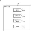
- the functional configuration of the control module 100 will be explained with reference to FIG.
- the control module 100 includes a communication section 101 , a processing execution section 102 , a program acquisition section 103 , and a storage section 104 .
- the communication unit 101 communicates with the expansion module 110 and the program creation device 40.
- the storage unit 104 stores a control program that is acquired from the program creation device 40 by a program acquisition unit 103 (described later) and executed by a processing execution unit 102 (described later). Furthermore, the storage unit 104 stores information indicating the priority of tasks associated with the control program and information indicating the execution cycle.
- the process execution unit 102 executes the control program stored in the storage unit 104 and repeatedly executes a plurality of control processes. As the processing execution unit 102 executes the control program, the safety control signal output from the input device 20 via the expansion module 110 is processed, and the output device 30 is controlled via the expansion module 110.
- the processing execution unit 102 executes the processing on a task-by-task basis. Further, the processing execution unit 102 executes the task by time-sharing processing as described above. For example, as described above, the processing execution unit 102 executes all of task A, then executes only half of task B, then executes only half of task C, and then executes all of task A again. It is conceivable to perform time-sharing processing in which the remaining half of task B is executed, then the remaining half of task B is executed, and finally the remaining half of task C is executed.
- how the processing execution unit 102 performs time-sharing processing is determined according to the priority of each task associated with the control program and the execution cycle of the task.
- the processing execution unit 102 executes each task in a time-sharing process based on the execution cycle of the high-priority task and the execution cycle of the entire task.
- the program acquisition unit 103 acquires the control program, information indicating the priority associated with the control program, and information indicating the execution cycle from the program creation device 40 via the communication unit 101, and stores the acquired information in the storage unit 104. do.
- the control program and related information are set in the PLC 10.
- the expansion module 110 includes a communication section 111 , a processing execution section 112 , a mode switching section 113 , a trigger detection section 114 , and a storage section 115 .
- the communication unit 111 communicates with the control module 100, the input device 20, and the output device 30.
- the storage unit 115 stores a control program executed by the processing execution unit 112, which will be described later.
- the processing execution unit 112 executes the control program stored in the storage unit 115. In normal times, the processing execution unit 112 performs control communication with the control module 100 and operates cooperatively with the control module 100 by executing a control program. Furthermore, by executing the control program, the processing execution unit 112 transmits a signal received from the input device 20 to the control module 100, and transmits a signal related to control of the output device 30 received from the control module 100 to the output device 30. do. Communication related to the input device 20 and output device 30 and performed with the control module 100 will be referred to as "input/output communication" below. The processing execution unit 112 performs cooperative operations based on control communication, and also executes processing related to input/output communication.
- the processing execution unit 112 blocks part or all of the communication with the control module. At this time, the processing execution unit 112 executes processing according to the communication that has been interrupted by the expansion module 110. For example, when only control communication is cut off, the processing execution unit 112 continues to execute only processing related to input/output communication. Further, for example, when both control communication and input/output communication are cut off, the processing execution unit 112 causes the expansion module 110 to operate independently while continuing communication with the input device 20 or communication with the output device 30. Execute the process. Whether communication with the control module is partially or completely blocked may vary depending on the settings of the expansion module 110.
- the mode switching unit 113 switches the operation mode of the expansion module 110 at the timing when a trigger detection unit 114 (described later) detects a trigger.
- the expansion module 110 operates in the first mode, which is the normal operating mode.
- This first mode is a mode in which the expansion module 110 performs cooperative operations with the control module 100 through control communication without interrupting communication with the control module 100. Normally, the expansion module 110 operates in this first mode.
- the mode switching unit 113 switches the operation mode to a second mode in which part or all of the communication between the expansion module 110 and the control module 100 is cut off.
- the processing execution unit 112 executes an operation corresponding to the second mode, that is, an operation corresponding to cutting off part or all of communication with the control module 100.
- the trigger detection unit 114 detects the situation as a trigger. Specifically, the trigger detection unit 114 detects, for example, at a predetermined timing, when the control module 100 executes a predetermined program command, and when an abnormality in the control module 100 is detected. Detect at least one of them as a trigger.
- FIG. 9 shows a case where only control communication is cut off
- FIG. 10 shows a case where not only control communication but also input/output communication between the control module 100 and the expansion module 110 is cut off.
- control communication is cut off.
- the control module 100 and the expansion module 110 no longer execute processes that depend on control communication, which reduces the processing load and shortens the response time.
- control communication is cut off, and input/output communication between the control module 100 and the expansion module 110 is also cut off.
- the expansion module 110 then operates independently rather than in a cooperative manner. As a result, the control module 100 no longer executes processes that depend on communication, and the expansion module 110 no longer executes processes that depend on control communication, which reduces the processing load and shortens the response time.
- control module 100 an example of the hardware configuration of the control module 100, the expansion module 110, and the program creation device 40 (hereinafter referred to as the control module 100, etc.) will be described with reference to FIG.
- the control module 100 and the like shown in FIG. 11 are realized by, for example, a computer such as a personal computer or a microcontroller.
- the control module 100 and the like include a processor 1001, a memory 1002, an interface 1003, and a secondary storage device 1004, which are connected to each other via a bus 1000.
- the processor 1001 is, for example, a CPU (Central Processing Unit). Each function of the control module 100 and the like is realized by the processor 1001 reading an operating program stored in the secondary storage device 1004 into the memory 1002 and executing it.
- CPU Central Processing Unit
- the memory 1002 is a main storage device composed of, for example, RAM (Random Access Memory).
- the memory 1002 stores an operating program read from the secondary storage device 1004 by the processor 1001. This operating program is, for example, firmware. Furthermore, the memory 1002 functions as a work memory when the processor 1001 executes an operating program.
- the interface 1003 is an I/O (Input/Output) interface such as a serial port, a USB (Universal Serial Bus) port, or a network interface.
- the interface 1003 realizes the functions of the communication unit 101, communication unit 111, and communication unit 401.
- the secondary storage device 1004 is, for example, a flash memory, an HDD (Hard Disk Drive), or an SSD (Solid State Drive). Secondary storage device 1004 stores operating programs executed by processor 1001. The functions of the storage unit 104, the storage unit 115, and the storage unit 408 are realized by the secondary storage device 1004.
- the priority setting unit 403 of the program creation device 40 sets the priority of each task (step S101).
- the cycle determination unit 404 of the program creation device 40 sets the relationship (iii) above so that the above relationship (iii) holds. In other words, the processing time of the high-priority task x 2 + the processing time per cycle of other tasks ⁇ the set response time of the high-priority task.
- the time-sharing processing is determined so that the following relationship holds true (step S102).
- the cycle determining unit 404 determines the execution cycle of the high priority task and the execution cycle of the entire task based on the time sharing process determined in step S102 (step S103).
- the association unit 405 of the program creation device 40 associates the control program with the priority set in step S101 and the execution cycle determined in step S103 (step S104). Then, the program creation device 40 ends the operation of determining the execution cycle. Note that after this, the PLC setting unit 406 of the program creation device 40 transmits the control program, information indicating the priority, and information indicating the execution cycle to the control module 100 of the PLC 10. Thereby, the processing execution unit 102 of the control module 100 can execute the control program based on the set priority and the determined execution cycle.
- the expansion module 110 is operating in the first mode, which is the normal operation mode.
- the trigger detection unit 114 of the expansion module 110 determines whether a trigger is detected (step S201).
- step S201: No When no trigger is detected (step S201: No), the expansion module 110 repeats the operation of step S201.
- step S201 When a trigger is detected (step S201: Yes), the mode switching unit 113 of the expansion module 110 switches the operation mode from the first mode to the second mode (step S202).
- the processing execution unit 112 cuts off communication with the control module 100 in response to the operation mode being switched to the second mode (step S203). Here, depending on the settings of the expansion module, whether some or all communications with the control module 100 are blocked may change. The expansion module 110 then ends the communication cutoff operation.
- the control system 1 has been described above.
- the program creation device 40 determines the execution cycle so that the high-priority task can be executed within the set response time, so the response time of the high-priority task can be easily shortened. In other words, response time can be easily managed.
- the expansion module 110 cuts off communication with the control module 100 when a trigger is detected, so there is no need to perform processing related to the communication, and the processing load is reduced. As a result, response time is reduced. In other words, response time can be easily managed.
- the program creation device 40 displays a GUI (Graphical User Interface) as shown in FIG. 14, for example, when the user creates a control program.
- the program creation device 40 displays the number of function blocks (FBs) that can be added while maintaining the current setting response time and the execution time of each FB in the "Number that can be added" column.
- the program creation device 40 displays information indicating the set response time and processing time in the current control program, and the current set value and settable range for the program execution cycle. Note that the descriptions such as 0.1 ms and 0.2 ms displayed at the bottom of each FB shown in FIG. 14 indicate the execution time of each FB.
- the program creation device 40 By displaying the GUI shown in FIG. 14 by the program creation device 40, the user can understand what kind of FB can be added while maintaining the set response time. In other words, response time can be easily managed. Furthermore, since the user can set the program execution cycle while checking the processing time, the program execution cycle can be easily changed.
- the functional configuration of the program creation device 40 according to the second embodiment is generally the same as that shown in FIG. 2, but there is an additional feature in the function of the screen generation unit 407.
- the screen generation unit 407 according to the second embodiment generates a screen showing the created control program.
- the screen generation unit 407 displays the control program in units of FBs using a GUI as shown in FIG. 14, for example. Further, the screen generation unit 407 generates a display indicating the set response time, processing time, and program execution cycle on the screen. In addition, the screen generation unit 407 generates a display on the screen indicating the types of commands that can be added to the control program and the number of commands that can be added for each command within a range where the response time is within the set response time. . In FIG.
- the types of instructions that can be added are represented by FBs.
- the number of instructions that can be added for each FB and the execution time of the instructions are displayed.
- the current response time of the control program is 0.5 ms, which is the sum of the execution times of each FB. Since the set response time is 5 ms, commands can be added for 4.5 ms.
- control system 1 according to the second embodiment has been described above. According to the control system 1 according to the second embodiment, since the control program of the PLC 10 is displayed on the GUI, the user can visually recognize the control program. Further, according to the control system 1 according to the second embodiment, the user can grasp which commands and how many commands can be added within a range where the response time is within the set response time. Therefore, the user can easily manage response time when adding a new command to the control program.
- the processing execution unit 102 of the control module 100 executes the control program, but not only the processing execution unit 102 of the control module 100 but also the processing execution unit 112 of the expansion module 110 executes the control program. may be executable.
- control module 100 and the like are equipped with a secondary storage device 1004.
- the present invention is not limited to this, and the secondary storage device 1004 may be provided outside the control module 100 or the like, and the control module 100 or the like may be connected to the secondary storage device 1004 via the interface 1003.
- removable media such as a USB flash drive or a memory card can also be used as the secondary storage device 1004.
- control module 100 etc. may be configured with a dedicated circuit using an ASIC (Application Specific Integrated Circuit), FPGA (Field Programmable Gate Array), etc. good.
- ASIC Application Specific Integrated Circuit
- FPGA Field Programmable Gate Array
- part of the functions of the control module 100 and the like may be realized by a dedicated circuit connected to the interface 1003, for example.
- the programs used in the control module 100 and the like are stored and distributed in computer-readable recording media such as CD-ROMs (Compact Disc Read Only Memory), DVDs (Digital Versatile Discs), USB flash drives, memory cards, HDDs, etc. Is possible.
- CD-ROMs Compact Disc Read Only Memory
- DVDs Digital Versatile Discs
- USB flash drives memory cards
- HDDs HDDs, etc.
- the above-mentioned program may be stored in a storage device of another server on the Internet, and the above-mentioned program may be downloaded from the server.
- control system 10 PLC, 20 input device, 30 output device, 40 program creation device, 100 control module, 101 communication section, 102 processing execution section, 103 program acquisition section, 104 storage section, 110 expansion module, 111 communication section, 112 Process execution unit, 113 Mode switching unit, 114 Trigger detection unit, 115 Storage unit, 401 Communication unit, 402 Program creation unit, 403 Priority setting unit, 404 Period determination unit, 405 Correlation unit, 406 PLC setting unit, 407 Screen generation unit, 408 storage unit, 409 display unit, 410 operation unit, 1000 bus, 1001 processor, 1002 memory, 1003 interface, 1004 secondary storage device.
Landscapes
- Physics & Mathematics (AREA)
- General Physics & Mathematics (AREA)
- Engineering & Computer Science (AREA)
- Automation & Control Theory (AREA)
- Programmable Controllers (AREA)
Priority Applications (2)
| Application Number | Priority Date | Filing Date | Title |
|---|---|---|---|
| PCT/JP2022/022927 WO2023238220A1 (ja) | 2022-06-07 | 2022-06-07 | プログラム作成装置、プログラム作成方法及びプログラム |
| JP2022566473A JP7241989B1 (ja) | 2022-06-07 | 2022-06-07 | プログラム作成装置、プログラム作成方法及びプログラム |
Applications Claiming Priority (1)
| Application Number | Priority Date | Filing Date | Title |
|---|---|---|---|
| PCT/JP2022/022927 WO2023238220A1 (ja) | 2022-06-07 | 2022-06-07 | プログラム作成装置、プログラム作成方法及びプログラム |
Publications (1)
| Publication Number | Publication Date |
|---|---|
| WO2023238220A1 true WO2023238220A1 (ja) | 2023-12-14 |
Family
ID=85600316
Family Applications (1)
| Application Number | Title | Priority Date | Filing Date |
|---|---|---|---|
| PCT/JP2022/022927 Ceased WO2023238220A1 (ja) | 2022-06-07 | 2022-06-07 | プログラム作成装置、プログラム作成方法及びプログラム |
Country Status (2)
| Country | Link |
|---|---|
| JP (1) | JP7241989B1 (https=) |
| WO (1) | WO2023238220A1 (https=) |
Families Citing this family (2)
| Publication number | Priority date | Publication date | Assignee | Title |
|---|---|---|---|---|
| CN116700135B (zh) | 2023-08-09 | 2023-10-20 | 长江三峡集团实业发展(北京)有限公司 | 可编程逻辑控制器任务调度方式的测试方法及装置 |
| WO2025229720A1 (ja) * | 2024-04-30 | 2025-11-06 | 三菱電機株式会社 | シーケンスロジックの作成方法、作成システムおよびプログラム |
Citations (3)
| Publication number | Priority date | Publication date | Assignee | Title |
|---|---|---|---|---|
| JP2012194682A (ja) * | 2011-03-15 | 2012-10-11 | Omron Corp | 制御装置およびシステムプログラム |
| WO2019097800A1 (ja) * | 2017-11-16 | 2019-05-23 | 株式会社日立産機システム | コントロール装置 |
| JP2021082027A (ja) * | 2019-11-19 | 2021-05-27 | 株式会社キーエンス | 安全コントローラ |
Family Cites Families (1)
| Publication number | Priority date | Publication date | Assignee | Title |
|---|---|---|---|---|
| DE19500957A1 (de) * | 1994-07-19 | 1996-01-25 | Bosch Gmbh Robert | Verfahren zur Steuerung von technischen Vorgängen oder Prozessen |
-
2022
- 2022-06-07 JP JP2022566473A patent/JP7241989B1/ja active Active
- 2022-06-07 WO PCT/JP2022/022927 patent/WO2023238220A1/ja not_active Ceased
Patent Citations (3)
| Publication number | Priority date | Publication date | Assignee | Title |
|---|---|---|---|---|
| JP2012194682A (ja) * | 2011-03-15 | 2012-10-11 | Omron Corp | 制御装置およびシステムプログラム |
| WO2019097800A1 (ja) * | 2017-11-16 | 2019-05-23 | 株式会社日立産機システム | コントロール装置 |
| JP2021082027A (ja) * | 2019-11-19 | 2021-05-27 | 株式会社キーエンス | 安全コントローラ |
Also Published As
| Publication number | Publication date |
|---|---|
| JPWO2023238220A1 (https=) | 2023-12-14 |
| JP7241989B1 (ja) | 2023-03-17 |
Similar Documents
| Publication | Publication Date | Title |
|---|---|---|
| WO2023238220A1 (ja) | プログラム作成装置、プログラム作成方法及びプログラム | |
| JP2010170536A (ja) | プログラマブル・コントローラ | |
| US20160091889A1 (en) | Numerical control system | |
| JP2012123673A (ja) | 給電切替装置、給電切替装置制御方法、及び給電制御プログラム | |
| US10956238B2 (en) | Programmable controller, management device, and control system | |
| JP2017187992A (ja) | 制御装置、制御方法およびプログラム | |
| US9582369B2 (en) | Monitoring method, monitoring device, and information processing system | |
| EP2733613B1 (en) | Controller and program | |
| EP3979148B1 (en) | Presenting method and system of machine learning automatic modeling process | |
| US20210187742A1 (en) | Control device and control method | |
| WO2023238221A1 (ja) | 拡張モジュール、動作モード切替方法及びプログラム | |
| US10983772B2 (en) | Method, apparatus and program for generating application program | |
| US20160266808A1 (en) | Information processing device, information processing method, and recording medium | |
| US12153532B2 (en) | Method for controlling a target memory by programmably selecting an action execution circuit module corresponding to a triggered preset state | |
| JP5365875B2 (ja) | 産業用コントローラ | |
| EP4141590A1 (en) | Support device, support program, and control system | |
| JP6191625B2 (ja) | インバータ制御装置およびその周辺装置 | |
| CN119487463A (zh) | 设定辅助装置、控制系统、设定辅助方法以及程序 | |
| CN114326507A (zh) | 机台控制方法、装置、电子设备及计算机可读存储介质 | |
| JPWO2014188764A1 (ja) | 機能安全制御装置 | |
| JP7399372B1 (ja) | 通信システム、通信方法、プログラム及び通信装置 | |
| US20170060666A1 (en) | Controller capable of detecting factor at time of abnormality of pc function | |
| JP3442083B2 (ja) | ジョブ制御システム | |
| WO2020235095A1 (ja) | プログラマブルロジックコントローラ、コンピュータ、方法、及びプログラム | |
| JP2009032060A (ja) | ロボット制御装置 |
Legal Events
| Date | Code | Title | Description |
|---|---|---|---|
| ENP | Entry into the national phase |
Ref document number: 2022566473 Country of ref document: JP Kind code of ref document: A |
|
| 121 | Ep: the epo has been informed by wipo that ep was designated in this application |
Ref document number: 22945729 Country of ref document: EP Kind code of ref document: A1 |
|
| NENP | Non-entry into the national phase |
Ref country code: DE |
|
| 122 | Ep: pct application non-entry in european phase |
Ref document number: 22945729 Country of ref document: EP Kind code of ref document: A1 |