WO2023234385A1 - 地図生成装置、地図生成方法、及びコンピュータ読み取り可能な記録媒体 - Google Patents
地図生成装置、地図生成方法、及びコンピュータ読み取り可能な記録媒体 Download PDFInfo
- Publication number
- WO2023234385A1 WO2023234385A1 PCT/JP2023/020403 JP2023020403W WO2023234385A1 WO 2023234385 A1 WO2023234385 A1 WO 2023234385A1 JP 2023020403 W JP2023020403 W JP 2023020403W WO 2023234385 A1 WO2023234385 A1 WO 2023234385A1
- Authority
- WO
- WIPO (PCT)
- Prior art keywords
- feature point
- feature points
- feature
- interest
- specific
- Prior art date
- Legal status (The legal status is an assumption and is not a legal conclusion. Google has not performed a legal analysis and makes no representation as to the accuracy of the status listed.)
- Ceased
Links
Images



Classifications
-
- G—PHYSICS
- G05—CONTROLLING; REGULATING
- G05D—SYSTEMS FOR CONTROLLING OR REGULATING NON-ELECTRIC VARIABLES
- G05D1/00—Control of position, course, altitude or attitude of land, water, air or space vehicles, e.g. using automatic pilots
- G05D1/02—Control of position or course in two dimensions
-
- G—PHYSICS
- G06—COMPUTING OR CALCULATING; COUNTING
- G06T—IMAGE DATA PROCESSING OR GENERATION, IN GENERAL
- G06T17/00—Three-dimensional [3D] modelling for computer graphics
- G06T17/05—Geographic models
-
- G—PHYSICS
- G06—COMPUTING OR CALCULATING; COUNTING
- G06T—IMAGE DATA PROCESSING OR GENERATION, IN GENERAL
- G06T7/00—Image analysis
- G06T7/50—Depth or shape recovery
- G06T7/55—Depth or shape recovery from multiple images
-
- G—PHYSICS
- G09—EDUCATION; CRYPTOGRAPHY; DISPLAY; ADVERTISING; SEALS
- G09B—EDUCATIONAL OR DEMONSTRATION APPLIANCES; APPLIANCES FOR TEACHING, OR COMMUNICATING WITH, THE BLIND, DEAF OR MUTE; MODELS; PLANETARIA; GLOBES; MAPS; DIAGRAMS
- G09B29/00—Maps; Plans; Charts; Diagrams, e.g. route diagram
Definitions
- the present disclosure relates to a map generation device and a map generation method for generating an environmental map constructed from point cloud data, and further relates to a program for realizing these.
- SLAM Simultaneous Localization and Mapping
- SLAM is a technology in which a moving body equipped with a camera simultaneously estimates its own position and creates an environmental map (for example, see Patent Document 1).
- a mobile object such as an autonomously traveling robot does not need to move randomly and can move along an autonomously traveling map obtained from an environmental map, thereby improving its movement efficiency.
- the moving object acquires image data output from a camera frame by frame, searches for feature points in the latest frame that correspond to feature points extracted from past frames, and searches for the corresponding feature points in the latest frame. Extract a set of feature points made up of the same feature points. Then, the moving object calculates the camera matrix in the latest frame using the set of feature points, and calculates the feature point for each set of feature points using the camera matrix and the two-dimensional coordinates of the feature point in the frame. Calculate the three-dimensional coordinates of
- the moving object calculates the position of the camera from the camera matrix and performs self-position estimation. Further, the mobile object uses the feature points whose three-dimensional coordinates have been calculated to generate or update an environmental map (hereinafter referred to as a "three-dimensional environmental map") made up of a three-dimensional point group. Thereafter, the mobile object generates an autonomous driving map by converting the three-dimensional environmental map into a two-dimensional one, and performs autonomous driving using the autonomous driving map.
- an environmental map hereinafter referred to as a "three-dimensional environmental map”
- a depth sensor that can measure the distance (depth) to an object for each pixel of image data is also used as the sensor.
- the density of the point cloud that makes up the environmental map can be made higher than when using a camera, and highly accurate autonomous driving becomes possible.
- a specific example of the depth sensor is a LiDAR (light detection and ranging) sensor (for example, see Patent Document 2).
- An example of the purpose of the present disclosure is to suppress a decrease in the accuracy of an environmental map even when a shield exists between a sensor and an object.
- a map generation device includes: a data acquisition unit that acquires image data output from the depth sensor in frame units; a feature point extraction unit that extracts feature points from the image data for each frame; For each frame, a specific feature point is selected from among the extracted feature points, and the depth of the selected feature point is aligned with the selected feature point in a specific direction of the image. a filtering unit that excludes the selected specific feature point when the minimum value of the depth of each feature point is greater than a threshold value; A set of corresponding feature points is identified between frames, further, the three-dimensional coordinates of the feature points identified as a set are calculated, and the calculation results are used to create a set of feature points identified as a set.
- an environmental map generation unit that generates an environmental map; It is characterized by having the following.
- a map generation method includes: a data acquisition step of acquiring image data output from the depth sensor in frame units; a feature point extraction step of extracting feature points from the image data for each frame; For each frame, a specific feature point is selected from among the extracted feature points, and the depth of the selected feature point is aligned with the selected feature point in a specific direction of the image. a filtering step of excluding the selected specific feature point when the minimum value of the depth of each feature point is greater than a threshold value; A set of corresponding feature points is identified between frames, further, the three-dimensional coordinates of the feature points identified as a set are calculated, and the calculation results are used to create a set of feature points identified as a set. an environmental map generation step of generating an environmental map based on the It is characterized by having.
- a program includes: to the computer, a data acquisition step of acquiring image data output from the depth sensor in frame units; a feature point extraction step of extracting feature points from the image data for each frame; For each frame, a specific feature point is selected from among the extracted feature points, and the depth of the selected feature point is aligned with the selected feature point in a specific direction of the image.
- an environmental map generation step of generating an environmental map based on the It is characterized by causing the execution of.
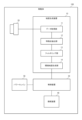
- FIG. 1 is a configuration diagram showing a schematic configuration of a map generation device.
- FIG. 2 is a configuration diagram specifically showing the configuration of the map generation device.
- FIG. 3 is an explanatory diagram for explaining the function of the filtering section.
- FIG. 4 is a diagram showing an example of a three-dimensional environmental map.
- FIG. 5 is a flow diagram showing the operation of the map generation device.
- FIG. 6 is a block diagram showing an example of a computer that implements the map generation device.
- FIG. 1 is a configuration diagram showing a schematic configuration of a map generation device.
- a map generation device 10 in the embodiment shown in FIG. 1 is a device for generating an environmental map constructed from point cloud data.
- the map generation device 10 includes a data acquisition section 11, a feature point extraction section 12, a filtering section 13, and an environmental map generation section 14.
- the data acquisition unit 11 acquires image data output from the depth sensor in units of frames.
- the feature point extraction unit 12 extracts feature points from the image data acquired by the data acquisition unit 11 for each frame.
- the filtering unit 13 selects specific feature points from the extracted feature points for each frame. In addition, the filtering unit 13 determines that the depth of the selected specific feature point is greater than or equal to a threshold value than the minimum value of the depths of each of a plurality of other feature points that are aligned with the selected specific feature point in a specific direction of the image. If it is larger, the selected feature point is excluded.
- the environmental map generation unit 14 identifies a set of corresponding feature points between frames, further calculates the three-dimensional coordinates of the feature points identified as the set, and uses the calculation result to determine the features identified as the set. Generate an environmental map composed of a set of points.
- the map generation device 10 selects a specific feature point, for example, a feature point that is an edge of an object, and determines that the depth of the selected feature point is different from that of another feature point arranged in the horizontal direction. If the depth is greater than a certain value than the minimum value, the selected feature point is excluded. In this case, the selected feature point is a feature point created by the shadow of an obstruction between the sensor and the object. As a result, according to the embodiment, even if a shield exists between the sensor and the object, it is possible to suppress a decrease in the accuracy of the environmental map.
- FIG. 2 is a configuration diagram specifically showing the configuration of the map generation device.
- FIG. 3 is an explanatory diagram for explaining the function of the filtering section.
- the map generation device 10 is mounted on a mobile object 100 that can autonomously travel, such as a robot.
- the mobile body 100 includes a depth sensor 20, a control device 30, a steering device 40, and a power train 50.
- the depth sensor 20 is attached to the moving body 100 so that the moving direction side of the moving body 100 is photographed. Further, the depth sensor 20 is a sensor capable of capturing images with depth, and outputs image data with depth at a set frame rate. In the example of FIG. 2, three-dimensional LiDAR is used as the depth sensor 20.
- the control device 30 is constructed by a computer mounted on the mobile object 100.
- the control device 30 controls the traveling direction and moving speed of the mobile object 100 using the environmental map generated by the map generation device 10. For example, the control device 30 uses an environmental map to set a route from the current location to a destination, and determines the traveling direction and speed of the moving object 100 so that the moving object 100 moves on the set route. to control the power train 50 and the steering device 40.
- the power train 50 is composed of an electric motor for driving, a power transmission mechanism, and the like. Tires, caterpillars, etc. are connected to the power train 50. The power train 50 rotates tires, caterpillars, etc. according to instructions from the control device 30.
- the steering device 40 includes a mechanism for controlling the direction of the steering wheels of the moving body 100.
- the steering device 40 determines the direction of the steered wheels in response to instructions from the control device 30. Further, the steering device 40 may include a mechanism that controls the direction of movement by controlling the torque of the left and right drive wheels.
- the map generation device 10 is constructed on a computer installed in the mobile object 100 using a program in the embodiment described later. Furthermore, the map generation device 10 may be constructed by a device (for example, an electronic circuit, etc.) that is different from the computer installed in the mobile object 100.
- the data acquisition unit 11 acquires image data with depth from the depth sensor 20 in units of frames.
- the data acquisition unit 11 sequentially inputs the acquired image data (frames) to the feature point extraction unit 12.
- the feature point extraction unit 12 when a frame is input, extracts feature points of the object for each frame using, for example, a general FAST algorithm. Then, the feature point extraction unit 12 inputs information specifying the feature points extracted for each frame to the filtering unit 13.
- the filtering unit 13 selects a specific feature point from among the extracted feature points for each frame.
- the filtering unit 13 calculates the curvature of a trajectory connecting the feature point of interest and a plurality of other feature points arranged in a specific direction of the image, and the calculated curvature is the threshold value. If this is the case, the feature point of interest is selected as a specific feature point. That is, as shown in FIG. 3, the filtering unit 13 selects a feature point of a portion that becomes an edge of the object as a specific feature point (hereinafter referred to as an "edge feature point").
- the feature points indicated by “ ⁇ ” are selected.
- the feature points indicated by “ ⁇ ” are feature points at the edge of the object (edge feature points), and the curvature there is greater than or equal to the threshold value.
- the feature points indicated by “ ⁇ ” are feature points of the plane portion of the object (hereinafter referred to as "plane feature points").
- 21 indicates the imaging area of the depth sensor 20.
- Reference numeral 22 indicates a wall existing in the real space
- reference numeral 23 indicates a shielding object existing between the depth sensor 20 and the wall (object) 22.
- the specific direction is the scanning direction of the depth sensor 20 near the feature point of interest. If the depth sensor 20 is a LiDAR, its scanning direction is determined by the specifications of the LiDAR.
- the filtering unit 13 first focuses on one of the extracted feature points, and identifies a plurality of other feature points that are lined up with this feature point (hereinafter referred to as "feature point of interest") in the scanning direction. . For example, in the scanning direction, the filtering unit 13 specifies five different feature points before and after the feature point of interest (10 in total), centering on the feature point of interest.
- the filtering unit 13 calculates the curvature c of the trajectory connecting the feature point of interest and a plurality of other feature points using, for example, Equation 1 below.
- Equation 1 i indicates a feature point of interest, and j indicates another feature point aligned with the feature point of interest.
- S indicates the number of other feature points that line up with the feature point of interest.
- X L (k, i) indicates the coordinates of the feature point i of interest in frame k
- X L (k, j) indicates the coordinates of feature point j in frame k.
- the filtering unit 13 selects the feature point of interest as an edge feature point when the calculated value of the curvature c is greater than or equal to the threshold (curvature c i ⁇ threshold). Furthermore, the filtering unit 13 can also select edge feature points only when the number of feature points whose curvature c value is equal to or greater than a threshold does not exceed an upper limit within the same frame. This is because if the number of feature points exceeds the upper limit, there is a high possibility that the feature point of interest is not a feature point created by shadows.
- the filtering unit 13 determines whether the depth d i of the edge feature point is greater than or equal to a threshold value than the minimum value of the depths of each of a plurality of other feature points arranged in the scanning direction. judge whether Specifically, the filtering unit 13 determines whether the following equation 2 is satisfied. As a result of the determination, if the depth is greater than or equal to the threshold (depth d i ⁇ MIN(d j ) ⁇ threshold), the filtering unit 13 excludes the selected edge feature point.
- the environmental map generation unit 14 first uses the feature points of each frame that were not excluded by the filtering unit 13 to associate the feature points extracted from each frame with the feature points extracted from past frames. , identify a set of feature points.
- the environmental map generation unit 14 calculates the camera matrix for each frame using the set of feature points identified in that frame.
- the environmental map generation unit 14 then calculates the three-dimensional coordinates of the feature point using the calculated camera matrix and the two-dimensional coordinates of the feature point in the frame.
- the environmental map generation unit 14 calculates the position of the camera from the camera matrix and performs self-position estimation. Further, the mobile object uses the feature points whose three-dimensional coordinates have been calculated to generate or update an environmental map (hereinafter referred to as a "three-dimensional environmental map") made up of a three-dimensional point group.
- FIG. 4 is a diagram showing an example of a three-dimensional environmental map.
- the environmental map generation unit 14 inputs the generated three-dimensional environmental map to the control device 30. Furthermore, the environmental map generation unit 14 can also generate a two-dimensional environmental map by converting a three-dimensional environmental map into a two-dimensional one. In this case, the environmental map generation unit 14 passes the generated two-dimensional environmental map to the control device 30. Thereafter, the control device 30 uses the obtained environmental map to control the moving direction and moving speed of the moving object.
- the depth sensor 20 is not limited to this.
- the depth sensor 20 may also include a two-dimensional LiDAR with a fixed angle of view and a TOF (Time Of Flight) camera that measures depth on a specific plane.
- the LiDAR used as the depth sensor 20 may be of a fixed type with a fixed angle of view, or may be of a rotating type with an unfixed angle of view.
- FIG. 5 is a flow diagram showing the operation of the map generation device.
- FIGS. 1 to 4 the map generation method is implemented by operating the map generation device 10. Therefore, the explanation of the map generation method in the embodiment will be replaced with the following explanation of the operation of the map generation device 10.
- the data acquisition unit 11 acquires the output image data (step A1). Further, after acquiring image data for the set number of frames, the data acquisition unit 11 inputs the acquired image data to the feature point extraction unit 12.
- the feature point extraction unit 12 extracts feature points for each frame (step A2). Further, the feature point extraction unit 12 outputs the extracted feature points to the filtering unit 13 for each frame.
- the filtering unit 13 selects edge feature points from the extracted feature points for each frame (step A3).
- step A3 the filtering 13 calculates, for each frame, the curvature of a trajectory connecting the feature point of interest and a plurality of other feature points lined up in the scanning direction of the depth sensor 20. If the calculated curvature is greater than or equal to a threshold, the feature point of interest is selected as an edge feature point.
- the filtering unit 13 determines that the depth of the edge feature point is greater than the minimum value of the depths of other feature points arranged in the scanning direction by more than a threshold value. Determine whether or not. (Step A4).
- the filtering unit 13 excludes edge feature points determined to be larger than the threshold in step A4 (step A5).
- the environmental map generation unit 14 associates the feature points extracted from the feature points extracted from the feature points extracted from the past frames with the feature points extracted from the past frames for each frame, and (Step A6).
- the environmental map generation unit 14 calculates the three-dimensional coordinates of the feature points identified as a set in step A6, and uses the calculation results to create an environmental map composed of a set of feature points identified as a set. Generate (step A7).
- the environmental map generation unit 14 inputs the environmental map generated in step A7 to the control device 30.
- the control device 30 uses the obtained environmental map to control the moving direction and moving speed of the moving object.
- the program in the embodiment may be any program that causes a computer to execute steps A1 to A7 shown in FIG. By installing and executing this program on a computer, the map generation device 10 and map generation method in the embodiment can be realized.
- the processor of the computer functions as a data acquisition unit 11, a feature point extraction unit 12, a filtering unit 13, and an environmental map generation unit 14 to perform processing.
- examples of the computer include a computer mounted on the mobile object 100.
- Other examples of computers include general-purpose PCs, smartphones, and tablet terminal devices.
- each computer may function as one of the data acquisition section 11, the feature point extraction section 12, the filtering section 13, and the environmental map generation section 14, respectively.
- FIG. 6 is a block diagram showing an example of a computer that implements the map generation device.
- the computer 110 includes a CPU (Central Processing Unit) 111, a main memory 112, a storage device 113, an input interface 114, a display controller 115, a data reader/writer 116, and a communication interface 117. Equipped with. These units are connected to each other via a bus 121 so that they can communicate data.
- CPU Central Processing Unit
- the computer 110 may include a GPU (Graphics Processing Unit) or an FPGA (Field-Programmable Gate Array) in addition to or in place of the CPU 111.
- the GPU or FPGA can execute the program in the embodiment.
- the CPU 111 loads the program in the embodiment, which is stored in the storage device 113 and is composed of a group of codes, into the main memory 112, and executes each code in a predetermined order to perform various calculations.
- Main memory 112 is typically a volatile storage device such as DRAM (Dynamic Random Access Memory).
- the program in the embodiment is provided stored in a computer-readable recording medium 120.
- the program in this embodiment may be distributed on the Internet connected via the communication interface 117.
- the storage device 113 includes semiconductor storage devices such as flash memory, in addition to hard disk drives.
- Input interface 114 mediates data transmission between CPU 111 and input devices 118 such as a keyboard and mouse.
- the display controller 115 is connected to the display device 119 and controls the display on the display device 119.
- the data reader/writer 116 mediates data transmission between the CPU 111 and the recording medium 120, reads programs from the recording medium 120, and writes processing results in the computer 110 to the recording medium 120.
- Communication interface 117 mediates data transmission between CPU 111 and other computers.
- the recording medium 120 include general-purpose semiconductor storage devices such as CF (Compact Flash (registered trademark)) and SD (Secure Digital), magnetic recording media such as flexible disks, or CD-ROMs. Examples include optical recording media such as ROM (Compact Disk Read Only Memory).
- map generation device 10 in the embodiment can also be realized by using hardware corresponding to each part, for example, an electronic circuit, instead of a computer with a program installed. Furthermore, a part of the map generation device 10 may be realized by a program, and the remaining part may be realized by hardware.
- the computer is not limited to the computer shown in FIG.
- a data acquisition unit that acquires image data output from the depth sensor in frame units; a feature point extraction unit that extracts feature points from the image data for each frame; For each frame, a specific feature point is selected from among the extracted feature points, and the depth of the selected feature point is aligned with the selected feature point in a specific direction of the image. a filtering unit that excludes the selected specific feature point when the minimum value of the depth of each feature point is greater than a threshold value; A set of corresponding feature points is identified between frames, further, the three-dimensional coordinates of the feature points identified as a set are calculated, and the calculation results are used to create a set of feature points identified as a set.
- an environmental map generation unit that generates an environmental map; It is equipped with A map generation device characterized by:
- the specific direction is a scanning direction of the depth sensor
- the filtering unit calculates a curvature of a trajectory connecting the feature point of interest and a plurality of other feature points that are aligned with the feature point of interest in the specific direction with the feature point of interest as the center.
- Map generation device according to appendix 2.
- an environmental map generation step of generating an environmental map based on the has A map generation method characterized by:
- a curvature of a trajectory connecting the feature point of interest and a plurality of other feature points lined up in the specific direction is calculated, and the calculated curvature is equal to or greater than a threshold value.
- the specific direction is a scanning direction of the depth sensor,
- a curvature of a trajectory connecting the feature point of interest and a plurality of other feature points that are aligned with the feature point of interest in the specific direction centered around the feature point of interest is calculated; Map generation method described in Appendix 6.
- a curvature of a trajectory connecting the feature point of interest and a plurality of other feature points lined up in the specific direction is calculated, and the calculated curvature is equal to or greater than a threshold value.
- the specific direction is a scanning direction of the depth sensor,
- a curvature of a trajectory connecting the feature point of interest and a plurality of other feature points that are aligned with the feature point of interest in the specific direction centered around the feature point of interest is calculated; The program described in Appendix 10.
- the present disclosure even when a shield exists between a sensor and an object, it is possible to suppress a decrease in the accuracy of an environmental map.
- the present disclosure is useful in fields where SLAM is used.
- Map generation device 11 Data acquisition section 12 Feature point extraction section 13 Filtering section 14 Environmental map generation section 20 Depth sensor 30 Control device 40 Steering device 50 Power train 100 Mobile object 110 Computer 111 CPU 112 Main memory 113 Storage device 114 Input interface 115 Display controller 116 Data reader/writer 117 Communication interface 118 Input device 119 Display device 120 Recording medium 121 Bus
Landscapes
- Engineering & Computer Science (AREA)
- Physics & Mathematics (AREA)
- General Physics & Mathematics (AREA)
- Theoretical Computer Science (AREA)
- Software Systems (AREA)
- Remote Sensing (AREA)
- Geometry (AREA)
- Computer Vision & Pattern Recognition (AREA)
- Educational Technology (AREA)
- Educational Administration (AREA)
- Business, Economics & Management (AREA)
- Mathematical Physics (AREA)
- Computer Graphics (AREA)
- Aviation & Aerospace Engineering (AREA)
- Radar, Positioning & Navigation (AREA)
- Automation & Control Theory (AREA)
- Processing Or Creating Images (AREA)
Priority Applications (1)
| Application Number | Priority Date | Filing Date | Title |
|---|---|---|---|
| JP2024524937A JP7744064B2 (ja) | 2022-06-03 | 2023-06-01 | 地図生成装置、地図生成方法、及びプログラム |
Applications Claiming Priority (2)
| Application Number | Priority Date | Filing Date | Title |
|---|---|---|---|
| JP2022091129 | 2022-06-03 | ||
| JP2022-091129 | 2022-06-03 |
Publications (1)
| Publication Number | Publication Date |
|---|---|
| WO2023234385A1 true WO2023234385A1 (ja) | 2023-12-07 |
Family
ID=89024974
Family Applications (1)
| Application Number | Title | Priority Date | Filing Date |
|---|---|---|---|
| PCT/JP2023/020403 Ceased WO2023234385A1 (ja) | 2022-06-03 | 2023-06-01 | 地図生成装置、地図生成方法、及びコンピュータ読み取り可能な記録媒体 |
Country Status (2)
| Country | Link |
|---|---|
| JP (1) | JP7744064B2 (https=) |
| WO (1) | WO2023234385A1 (https=) |
Citations (1)
| Publication number | Priority date | Publication date | Assignee | Title |
|---|---|---|---|---|
| WO2021200432A1 (ja) * | 2020-03-30 | 2021-10-07 | パナソニックIpマネジメント株式会社 | 撮影指示方法、撮影方法、撮影指示装置及び撮影装置 |
Family Cites Families (1)
| Publication number | Priority date | Publication date | Assignee | Title |
|---|---|---|---|---|
| CN109961021B (zh) * | 2019-03-05 | 2020-11-10 | 北京超维度计算科技有限公司 | 一种深度图像中人脸检测方法 |
-
2023
- 2023-06-01 JP JP2024524937A patent/JP7744064B2/ja active Active
- 2023-06-01 WO PCT/JP2023/020403 patent/WO2023234385A1/ja not_active Ceased
Patent Citations (1)
| Publication number | Priority date | Publication date | Assignee | Title |
|---|---|---|---|---|
| WO2021200432A1 (ja) * | 2020-03-30 | 2021-10-07 | パナソニックIpマネジメント株式会社 | 撮影指示方法、撮影方法、撮影指示装置及び撮影装置 |
Non-Patent Citations (1)
| Title |
|---|
| TAZAKI, YUICHI: "A Survey of LiDAR-Based SLAM Techniques", SYSTEMS, CONTROL AND INFORMATION, SHISUTEMU SEIGYO JOHO GAKKAI, KYOTO, JP, vol. 64, no. 2, 15 February 2020 (2020-02-15), JP , pages 51 - 56, XP009551408, ISSN: 0916-1600, DOI: 10.11509/isciesci.64.2_51 * |
Also Published As
| Publication number | Publication date |
|---|---|
| JP7744064B2 (ja) | 2025-09-25 |
| JPWO2023234385A1 (https=) | 2023-12-07 |
Similar Documents
| Publication | Publication Date | Title |
|---|---|---|
| CN109084746B (zh) | 用于具有辅助传感器的自主平台引导系统的单目模式 | |
| KR101776622B1 (ko) | 다이렉트 트래킹을 이용하여 이동 로봇의 위치를 인식하기 위한 장치 및 그 방법 | |
| US9990736B2 (en) | Robust anytime tracking combining 3D shape, color, and motion with annealed dynamic histograms | |
| KR101725060B1 (ko) | 그래디언트 기반 특징점을 이용한 이동 로봇의 위치를 인식하기 위한 장치 및 그 방법 | |
| KR101784183B1 (ko) | ADoG 기반 특징점을 이용한 이동 로봇의 위치를 인식하기 위한 장치 및 그 방법 | |
| EP2671384B1 (en) | Mobile camera localization using depth maps | |
| KR101708659B1 (ko) | 이동 로봇의 맵을 업데이트하기 위한 장치 및 그 방법 | |
| AU2020317303B2 (en) | Information processing device, data generation method, and program | |
| CN110807350A (zh) | 用于面向扫描匹配的视觉slam的系统和方法 | |
| JP2019537715A (ja) | 障害物検出システム及び方法 | |
| EP3159126A1 (en) | Device and method for recognizing location of mobile robot by means of edge-based readjustment | |
| KR20200050246A (ko) | 2차원 영상으로부터 3차원 객체를 검출하는 방법 및 장치 | |
| KR20220160850A (ko) | 소실점을 추정하는 방법 및 장치 | |
| KR102917989B1 (ko) | 동적 장면에서의 차간 거리 보정을 위한 광학 흐름 기반 차량 자세 추정 방법 및 시스템 | |
| CN112700486B (zh) | 对图像中路面车道线的深度进行估计的方法及装置 | |
| Costa et al. | Robust 3/6 DoF self-localization system with selective map update for mobile robot platforms | |
| JP7517675B2 (ja) | 地図データ生成装置、地図データ生成方法、及びプログラム | |
| CN114509079A (zh) | 用于自主驾驶的地面投影的方法和系统 | |
| WO2021098666A1 (zh) | 手部姿态检测方法和装置、及计算机存储介质 | |
| WO2020079309A1 (en) | Obstacle detection | |
| WO2023234385A1 (ja) | 地図生成装置、地図生成方法、及びコンピュータ読み取り可能な記録媒体 | |
| JP7740683B2 (ja) | 位置推定装置、位置推定方法、及びプログラム | |
| CN116740160B (zh) | 一种复杂交通场景中的毫秒级多平面实时提取方法及装置 | |
| JP7701101B2 (ja) | 地図生成装置、地図生成方法、及びプログラム | |
| JP7553090B2 (ja) | 位置推定装置、位置推定方法、及びプログラム |
Legal Events
| Date | Code | Title | Description |
|---|---|---|---|
| 121 | Ep: the epo has been informed by wipo that ep was designated in this application |
Ref document number: 23816142 Country of ref document: EP Kind code of ref document: A1 |
|
| WWE | Wipo information: entry into national phase |
Ref document number: 2024524937 Country of ref document: JP |
|
| NENP | Non-entry into the national phase |
Ref country code: DE |
|
| 122 | Ep: pct application non-entry in european phase |
Ref document number: 23816142 Country of ref document: EP Kind code of ref document: A1 |