WO2023233538A1 - 電動機のコア - Google Patents
電動機のコア Download PDFInfo
- Publication number
- WO2023233538A1 WO2023233538A1 PCT/JP2022/022184 JP2022022184W WO2023233538A1 WO 2023233538 A1 WO2023233538 A1 WO 2023233538A1 JP 2022022184 W JP2022022184 W JP 2022022184W WO 2023233538 A1 WO2023233538 A1 WO 2023233538A1
- Authority
- WO
- WIPO (PCT)
- Prior art keywords
- core
- pin
- cross
- section
- pin hole
- Prior art date
- Legal status (The legal status is an assumption and is not a legal conclusion. Google has not performed a legal analysis and makes no representation as to the accuracy of the status listed.)
- Ceased
Links
Images




Classifications
-
- H—ELECTRICITY
- H02—GENERATION; CONVERSION OR DISTRIBUTION OF ELECTRIC POWER
- H02K—DYNAMO-ELECTRIC MACHINES
- H02K1/00—Details of the magnetic circuit
- H02K1/06—Details of the magnetic circuit characterised by the shape, form or construction
- H02K1/12—Stationary parts of the magnetic circuit
- H02K1/18—Means for mounting or fastening magnetic stationary parts on to, or to, the stator structures
-
- H—ELECTRICITY
- H02—GENERATION; CONVERSION OR DISTRIBUTION OF ELECTRIC POWER
- H02K—DYNAMO-ELECTRIC MACHINES
- H02K1/00—Details of the magnetic circuit
- H02K1/06—Details of the magnetic circuit characterised by the shape, form or construction
- H02K1/22—Rotating parts of the magnetic circuit
- H02K1/28—Means for mounting or fastening rotating magnetic parts on to, or to, the rotor structures
- H02K1/30—Means for mounting or fastening rotating magnetic parts on to, or to, the rotor structures using intermediate parts, e.g. spiders
Definitions
- Embodiments of the present invention relate to a core of an electric motor.
- a core of an electric motor includes a stator and a rotor that rotates with respect to the stator (for example, Japanese Patent Application Publication No. 2010-259256).
- the core of such a motor may be a laminate formed by laminating a plurality of magnetic plates, such as iron plates, carbon steel plates, and electromagnetic steel plates, in the axial direction of the core.
- a plurality of through holes are formed in each of the plurality of magnetic plates.
- a plurality of through holes in adjacent magnetic plates are aligned with each other to form a plurality of pin holes. Therefore, inside the core, a plurality of pin holes extend in the stacking direction of the core (in the axial direction of the core). Then, a plurality of pins are press-fitted into the plurality of pin holes from the end face of the core, thereby bonding the plurality of magnetic plates to each other and forming a strong core.
- a plurality of pin holes are formed in an end surface of the core, and further includes a plurality of pins inserted into each of the plurality of pin holes.
- At least one of the plurality of pins includes a curved portion that is at least partially curved with respect to the axial direction of the at least one pin, and the at least one pin is inserted into the plurality of pins.
- a core is provided, wherein at least one of the pin holes is configured to fit the curved portion of the at least one pin.
- FIG. 1 is a sectional view of an electric motor according to a first embodiment of the present invention.
- 2 is a radial cross-sectional view of the rotor shown in FIG. 1;
- FIG. 2B is a partial axial cross-sectional view of the rotor taken along line A-A' in FIG. 2A; It is a figure which shows the first modification of a pin hole. It is a figure which shows the second modification of a pin hole. It is a figure which shows the third modification of a pin hole. It is a figure which shows the fourth modification of a pin hole.
- FIG. 3 is a perspective view of a pin having a C-shaped cross section and a pin having an annular cross section.
- FIG. 3 is a partial radial cross-sectional view of a rotor according to a second embodiment of the invention.
- FIG. 7 is a partial radial cross-sectional view of a rotor according to a third embodiment of the invention.
- FIG. 7 is a partial radial cross-sectional view of a rotor according to a fourth embodiment of the present invention.
- FIG. 7 is a partial radial cross-sectional view of a rotor based on another modification of the fourth embodiment.
- FIG. 7 is a partial radial cross-sectional view of a rotor based on yet another modification of the fourth embodiment.
- FIG. 7 is a partial radial cross-sectional view of a rotor according to a fifth embodiment of the invention.
- FIG. 7 is another partial radial cross-sectional view of a rotor according to a fifth embodiment of the invention.
- FIG. 7 is a partial axial cross-sectional view of a rotor according to
- FIG. 1 is a sectional view of an electric motor according to a first embodiment of the present invention.
- the electric motor 1 includes a stator 9 and a rotor 10 rotatably supported by the stator 9.
- a first bearing 7 and a second bearing 8 are arranged on the inner peripheral surface of the stator 9.
- a shaft portion 5 passing through the rotor 9 is rotatably supported by the stator 9 by a first bearing 7 and a second bearing 8.
- a detector 6 is attached to one end of the stator 9 to detect the rotational speed of the shaft portion 5 and the like.
- the rotor 10 of the electric motor 1 will be used as the "core of the electric motor” in this specification.
- the “core of the motor” includes the stator 9 of the motor 1 and that the following description also applies to the core as stator 9.
- FIG. 2A is a radial cross-sectional view of the rotor shown in FIG. 1
- FIG. 2B is a partial axial cross-sectional view of the rotor taken along line A-A' in FIG. 2A.
- the rotor 10 is annular and has a hole formed in its center into which the shaft 5 (not shown in FIG. 2A) is inserted.
- the rotor 10 is formed by laminating a plurality of magnetic plates (core plates) 11 having the same shape, such as iron plates, carbon steel plates, and electromagnetic steel plates in the axial direction of the rotor 10.
- the rotor 10 and the stator 9 do not need to be formed from a plurality of magnetic plates 11, and the rotor 10 and the stator 9 may be made of a ferrite core, a powdered iron core, or the like. It may be an integral member made from a magnetic material.
- each of the plurality of magnetic plates 11 is formed with (a plurality of) through holes.
- the through holes are aligned with each other to form the pin holes 12 described above.
- a pin 20 is inserted into each of the plurality of pin holes 12 in the axial direction of the rotor 10. Strictly speaking, the pins 20 are press-fitted into corresponding pin holes 12 for the purpose of fastening adjacent magnetic plates 11 to each other.
- the pin 20 may have a curved portion 21 that is at least partially curved in its axial direction. Such a curved portion 21 contacts the inner wall of the pin hole 12, and as a result, frictional resistance increases and it may be difficult to press fit the pin 20 into the pin hole 12.
- At least one pin hole 12 among the plurality of pin holes 12 is formed to fit the curved portion 21 of the pin 20.
- the pin hole 12 is formed to accommodate the curved portion 21 of the pin 20.
- such a pin hole 12 has an elliptical cross section in the radial direction of the rotor 10.
- the contact area between the pin 20 and the rotor 10 is reduced, and the frictional resistance when the pin 20 is press-fitted into the pin hole 12 is reduced. Therefore, the pin 20 can be easily press-fitted into the pin hole 12, and the plurality of magnetic plates 11 can be firmly connected. As a result, the production efficiency of the rotor 10 can be improved.
- FIG. 4 is a perspective view of a pin with a C-shaped cross section and a pin with an annular cross section.
- a pin 20 with a C-shaped cross section is shown on the left side of FIG. 4, and a pin 20' with an annular cross section is shown on the right side of FIG.
- C-shaped pins 20 were often used in order to easily press-fit the pins 20 into the pin holes 12, but the C-shaped pins 20 had the disadvantage of being relatively expensive.
- the pin hole 12 is formed to fit the curved portion 21 of the pin 20, so the pin 20 can be press-fitted relatively easily. Therefore, in the first embodiment, it is not necessary to use the relatively expensive C-shaped pin 20, and it is possible to use the relatively inexpensive annular pin 20'. As can be seen, the manufacturing cost of the rotor 10 can therefore be reduced. Note that, as a matter of course, the C-shaped pin 20 may also be used in the first embodiment.
- FIGS. 3A to 3D are diagrams showing modified examples of pin holes.
- FIG. 3A shows a pin hole 12a having an oval cross section, similar to FIG. 2A and the like.
- the longest line segment R1a that connects the center of the cross section and the edge of the cross section with the longest distance and the shortest line segment that connects the center of the cross section and the edge of the cross section with the shortest distance.
- R2a can be defined.
- the longest line segment R1a and the shortest line segment R2a correspond to the long axis and short axis of the ellipse, respectively.
- FIG. 3B shows a pin hole 12b with a rectangular cross section.
- the longest line segment R1b that connects the center of the cross section and the edge of the cross section with the longest distance and the shortest line segment R2b that connects the center of the cross section and the edge of the cross section with the shortest distance.
- FIG. 3C shows a pin hole 12c with an oval cross section
- FIG. 3D shows a pin hole 12d with an elongated hexagonal cross section.
- the shortest line segment R2c that connects the center of the cross section and the edge of the cross section with the shortest distance.
- the longest line segment R1d that connects the center of the cross section and the edge of the cross section with the longest distance can be defined.
- the pin holes 12a to 12d overlap the original pin holes 12a to 12d when rotated by 180 degrees around the center of each cross section. Therefore, the pin holes 12a to 12d have "two-fold symmetry.”
- the diameter of the pin 20 is approximately equal to the shortest line segment R2a to R2d of the pin holes 12a to 12d. Therefore, the pin 20 is arranged so that the curved portion 21 of the pin 20 is directed toward the side edge of the longest line segment R1a to R1d of the pin holes 12a to 12d, or so that the curved portion 21 is located on the longest line segment R1a to R1d. is preferably positioned relative to the pin hole 12. After or while positioning, the pins 20 are press-fitted into the pin holes 12a to 12d.
- the curved portion 21 of the pin 20 does not or hardly contacts the side edges of the longest line segments R1a to R1d. Therefore, the frictional resistance when press-fitting the pin 20 into the pin hole 12 is reduced, and the pin 20 can be press-fitted easily. Therefore, effects similar to those described above can be obtained.
- the cross section of the pin hole 12 may have another shape having two-fold symmetry, such as an elongated polygon. In such a case, it will be understood that the manufacturing cost of the rotor 10 can be reduced.
- FIGS. 5A and 5B are partial radial cross-sectional views of rotors according to the second and third embodiments of the present invention.
- FIGS. 5A and 5B only a portion of the rotor 10 is shown when the electric motor 1 incorporating the rotor 10 is being driven.
- centrifugal force FC due to rotation of rotor 10 acts in the radial direction of rotor 10
- force FR due to torque reaction acts in the circumferential direction of rotor 10.
- a plurality of pin holes 12 having an oval cross section are formed in the rotor 10.
- the electric motor 1 in the second embodiment is, for example, a large torque motor.
- the pin 20 may move in the circumferential direction of the rotor 10 when the electric motor 1 is driven, and the coupling between the plurality of magnetic plates 11 may become insufficient. be.
- the pin 20 comes into contact with the pin hole 12 without any gap in the circumferential direction of the rotor 10. Therefore, in the second embodiment, the pin 20 does not move in the circumferential direction even when the electric motor 1 is driven, and as a result, the electric motor 1 can be driven stably.
- the centrifugal force FC is greater than the reaction force FR. That is, the electric motor 1 in the third embodiment is, for example, a high-speed rotation type motor. In such an electric motor 1, as shown in FIG. 5B, it is preferable to form the pin hole 12 so that the longest line segment R1a (see FIG. 3A, etc.) of the pin hole 12 extends in the circumferential direction of the rotor 10. preferable.
- the pin 20 does not move in the radial direction even when the electric motor 1 is driven, and as a result, the electric motor 1 can be driven stably.
- FIG. 6 is a partial radial cross-sectional view of a rotor according to a fourth embodiment of the present invention, and is a view similar to FIGS. 5A and 5B.
- the centrifugal force FC and the reaction force FR are approximately equal to each other.
- a plurality of pin holes 12e, 12f, 12g, 12h, and 12i are formed at equal intervals in the circumferential direction of the rotor 10.
- the pin holes 12e, 12g, 12i are inclined clockwise with respect to the radial direction of the rotor 10
- the pin holes 12f, 12h are inclined counterclockwise with respect to the radial direction of the rotor 10. ing.
- clockwise inclined pin holes 12e, 12g, 12i and counterclockwise inclined pin holes 12f, 12h are arranged alternately.
- the angle A1 at which the pin hole 12h is inclined counterclockwise with respect to the radial direction of the rotor 10 is approximately equal to the angle A2 at which the pin hole 12i is inclined clockwise with respect to the radial direction of the rotor 10. preferable.
- the electric motor 1 can be driven more stably.
- FIG. 7A is a partial radial sectional view of a rotor based on another modification of the fourth embodiment
- FIG. 7B is a partial radial sectional view of a rotor based on still another modification of the fourth embodiment. It is. 7A and 7B are similar to FIGS. 5A and 5B, and in these drawings as well, it is assumed that the centrifugal force FC and the reaction force FR are approximately equal to each other.
- a plurality of pin holes 12j, 12k, 12l, 12m, 12n, 12o, and 12p are formed at equal intervals in the circumferential direction of the rotor 10.
- the pin holes 12j, 12m, and 12n are inclined clockwise with respect to the radial direction of the rotor 10.
- the pin holes 12k, 12l, 12o, and 12p are inclined counterclockwise with respect to the radial direction of the rotor 10. Therefore, every second pin hole 12k, 12l, 12o, 12p tilted counterclockwise and pin hole 12j, 12m, 12n tilted clockwise are arranged. It is clear that even in such a case, the same effects as described above can be obtained. Further, a counterclockwise inclined pin hole and a clockwise inclined pin hole may be arranged every plurality (three or more).
- a plurality of pin holes 12q, 12r, 12s, 12t, 12u, 12v, and 12w are formed at equal intervals in the circumferential direction of the rotor 10.
- the pin holes 12s and 12w are inclined clockwise with respect to the radial direction of the rotor 10.
- the pin holes 12q, 12r, 12t, 12u, and 12v are inclined counterclockwise with respect to the radial direction of the rotor 10. Therefore, the counterclockwise inclined pin holes 12q, 12r, 12t, 12u, and 12v and the clockwise inclined pin holes 12s and 12w are randomly arranged.
- some of the pin holes are tilted counterclockwise, and the remaining pin holes are tilted clockwise.
- the number of pin holes tilted counterclockwise and the number of pin holes tilted clockwise are approximately equal to each other. It is obvious that the same effects as described above can be obtained with such a configuration as well.
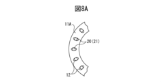
- FIG. 8A is a partial radial cross-sectional view of a rotor according to a fifth embodiment of the present invention
- FIG. 8B is another partial radial cross-sectional view of a rotor according to a fifth embodiment of the present invention
- FIG. 8C is a partial radial cross-sectional view of a rotor according to a fifth embodiment of the present invention
- FIG. 3 is a partial axial sectional view of a rotor according to a fifth embodiment of the present invention.
- a plurality of pin holes 12 are formed at equal intervals in the circumferential direction of the magnetic plate 11A.
- a plurality of pin holes 12' are formed at equal intervals in the circumferential direction of the magnetic plate 11B.
- the plurality of pin holes 12' in FIG. 8B are arranged radially outward than the plurality of pin holes 12 shown in FIG. 8A.
- the cross section of the pin hole 12 in the fifth embodiment does not need to have two-fold symmetry, and the cross section of the pin hole 12 in the fifth embodiment may be circular.
- a plurality of magnetic plates 11B are arranged above and below the rotor 10.
- the plurality of magnetic plates 11A are arranged between the plurality of upper magnetic plates 11B and the plurality of lower magnetic plates 11B.
- a pin hole 12x having a stepped inner surface is formed.
- the curved portion 21 of the pin 20 will fit along the stepped portion of the pin hole 12x. That is, in the fifth embodiment, the positions of the plurality of through holes in each of the magnetic plates 11A and 11B are made different from each other depending on the curved portion 21 of the pin 20. With such a configuration, the frictional resistance when press-fitting the pin 20 into the pin hole 12x is reduced, and the pin 20 can be press-fitted easily. Therefore, effects similar to those described above can be obtained.
- the number of magnetic plates 11B on the upper and lower sides of the rotor 10 and the number of the plurality of magnetic plates 11A are changed as appropriate depending on the shape of the curved portion 21 of the pin 20. Further, the number of magnetic plates 11B above or below the rotor 10 may be zero. Furthermore, it is within the scope of the fifth embodiment to use three or more types of magnetic plates with different positions of through holes so that a plurality of steps are formed.
- the pin hole 12 has a shape that matches/accommodates the curved portion 21 of the pin 20. Therefore, since the pin hole 12 has such a shape, when the pin 20 is press-fitted into the pin hole 12, the contact area between the pin 20 and the rotor 10 can be reduced, and the frictional resistance can be reduced. Therefore, the pin 20 can be easily press-fitted into the pin hole 12, and the plurality of magnetic plates 11 can be firmly connected. As a result, the production efficiency of the rotor 10 can be improved.
- the core in the embodiment described above may be applied to an electromagnetic device other than an electric motor, such as a core of a reactor or a transformer, and even such a case is within the scope of the present invention.
Landscapes
- Engineering & Computer Science (AREA)
- Power Engineering (AREA)
- Iron Core Of Rotating Electric Machines (AREA)
Priority Applications (2)
| Application Number | Priority Date | Filing Date | Title |
|---|---|---|---|
| PCT/JP2022/022184 WO2023233538A1 (ja) | 2022-05-31 | 2022-05-31 | 電動機のコア |
| JP2024524039A JPWO2023233538A1 (https=) | 2022-05-31 | 2022-05-31 |
Applications Claiming Priority (1)
| Application Number | Priority Date | Filing Date | Title |
|---|---|---|---|
| PCT/JP2022/022184 WO2023233538A1 (ja) | 2022-05-31 | 2022-05-31 | 電動機のコア |
Publications (1)
| Publication Number | Publication Date |
|---|---|
| WO2023233538A1 true WO2023233538A1 (ja) | 2023-12-07 |
Family
ID=89026000
Family Applications (1)
| Application Number | Title | Priority Date | Filing Date |
|---|---|---|---|
| PCT/JP2022/022184 Ceased WO2023233538A1 (ja) | 2022-05-31 | 2022-05-31 | 電動機のコア |
Country Status (2)
| Country | Link |
|---|---|
| JP (1) | JPWO2023233538A1 (https=) |
| WO (1) | WO2023233538A1 (https=) |
Citations (3)
| Publication number | Priority date | Publication date | Assignee | Title |
|---|---|---|---|---|
| JPS54152103A (en) * | 1978-05-23 | 1979-11-30 | Fuji Electric Co Ltd | Lamination of stator core of revolving armature |
| JPS59226632A (ja) * | 1983-06-02 | 1984-12-19 | Matsushita Electric Ind Co Ltd | ブラシレス電動機 |
| JPS63198372U (https=) * | 1988-05-26 | 1988-12-21 |
-
2022
- 2022-05-31 JP JP2024524039A patent/JPWO2023233538A1/ja active Pending
- 2022-05-31 WO PCT/JP2022/022184 patent/WO2023233538A1/ja not_active Ceased
Patent Citations (3)
| Publication number | Priority date | Publication date | Assignee | Title |
|---|---|---|---|---|
| JPS54152103A (en) * | 1978-05-23 | 1979-11-30 | Fuji Electric Co Ltd | Lamination of stator core of revolving armature |
| JPS59226632A (ja) * | 1983-06-02 | 1984-12-19 | Matsushita Electric Ind Co Ltd | ブラシレス電動機 |
| JPS63198372U (https=) * | 1988-05-26 | 1988-12-21 |
Also Published As
| Publication number | Publication date |
|---|---|
| JPWO2023233538A1 (https=) | 2023-12-07 |
Similar Documents
| Publication | Publication Date | Title |
|---|---|---|
| JP5310872B2 (ja) | ロータ | |
| US7766133B2 (en) | Insert and retainer for securing same to an aircraft brake disk | |
| JP6627082B2 (ja) | 電動機 | |
| US7019428B2 (en) | Induction motor and rotor therefor | |
| CN110462984B (zh) | 转子和马达 | |
| US11303172B2 (en) | Rotor for rotating electrical machine and rotor core support structure for rotating electrical machine | |
| CN110383636A (zh) | 旋转电机的转子以及旋转电机 | |
| WO2018116738A1 (ja) | 回転電機の回転子、及び回転電機 | |
| JP6601169B2 (ja) | 回転電機 | |
| JPWO2019150527A1 (ja) | 回転電機のロータ及び回転電機 | |
| CN112055929B (zh) | 转子单元和电动机 | |
| US20200227963A1 (en) | Rotor core of rotating electrical machine | |
| US20170093233A1 (en) | Brushless Motor | |
| US20170093262A1 (en) | Brushless Motor | |
| WO2023233538A1 (ja) | 電動機のコア | |
| JP7544871B2 (ja) | 端板を備える回転子及び電動機 | |
| US9106116B2 (en) | Rotor of rotating electrical machine | |
| JP4056725B2 (ja) | ターボ分子ポンプ用ディスク | |
| US12218548B2 (en) | Embedded magnet rotor and rotary electric machine | |
| US20170093264A1 (en) | Brushless Motor | |
| US20170093259A1 (en) | Brushless Motor | |
| JP4244325B2 (ja) | 回転電機のロータ | |
| JP2021196030A (ja) | 玉軸受用保持器 | |
| US20230112429A1 (en) | Rotor and motor including same | |
| US11125273B1 (en) | Bearing cage assembly including metal shell |
Legal Events
| Date | Code | Title | Description |
|---|---|---|---|
| 121 | Ep: the epo has been informed by wipo that ep was designated in this application |
Ref document number: 22944825 Country of ref document: EP Kind code of ref document: A1 |
|
| ENP | Entry into the national phase |
Ref document number: 2024524039 Country of ref document: JP Kind code of ref document: A |
|
| NENP | Non-entry into the national phase |
Ref country code: DE |
|
| 122 | Ep: pct application non-entry in european phase |
Ref document number: 22944825 Country of ref document: EP Kind code of ref document: A1 |