WO2023233538A1 - Core of electric motor - Google Patents
Core of electric motor Download PDFInfo
- Publication number
- WO2023233538A1 WO2023233538A1 PCT/JP2022/022184 JP2022022184W WO2023233538A1 WO 2023233538 A1 WO2023233538 A1 WO 2023233538A1 JP 2022022184 W JP2022022184 W JP 2022022184W WO 2023233538 A1 WO2023233538 A1 WO 2023233538A1
- Authority
- WO
- WIPO (PCT)
- Prior art keywords
- core
- pin
- cross
- section
- pin hole
- Prior art date
Links
- 238000006243 chemical reaction Methods 0.000 claims description 10
- 238000010030 laminating Methods 0.000 claims description 3
- 230000004048 modification Effects 0.000 description 8
- 238000012986 modification Methods 0.000 description 8
- XEEYBQQBJWHFJM-UHFFFAOYSA-N Iron Chemical compound [Fe] XEEYBQQBJWHFJM-UHFFFAOYSA-N 0.000 description 5
- 230000000694 effects Effects 0.000 description 4
- 238000004519 manufacturing process Methods 0.000 description 4
- 229910000975 Carbon steel Inorganic materials 0.000 description 2
- 229910000831 Steel Inorganic materials 0.000 description 2
- 239000010962 carbon steel Substances 0.000 description 2
- 230000008878 coupling Effects 0.000 description 2
- 238000010168 coupling process Methods 0.000 description 2
- 238000005859 coupling reaction Methods 0.000 description 2
- 229910052742 iron Inorganic materials 0.000 description 2
- 239000010959 steel Substances 0.000 description 2
- 238000007792 addition Methods 0.000 description 1
- 238000012217 deletion Methods 0.000 description 1
- 230000037430 deletion Effects 0.000 description 1
- 238000010586 diagram Methods 0.000 description 1
- 239000000696 magnetic material Substances 0.000 description 1
- 238000000034 method Methods 0.000 description 1
- 230000002093 peripheral effect Effects 0.000 description 1
- 239000012256 powdered iron Substances 0.000 description 1
- 238000006467 substitution reaction Methods 0.000 description 1
- 229910000859 α-Fe Inorganic materials 0.000 description 1
Images


Classifications
-
- H—ELECTRICITY
- H02—GENERATION; CONVERSION OR DISTRIBUTION OF ELECTRIC POWER
- H02K—DYNAMO-ELECTRIC MACHINES
- H02K1/00—Details of the magnetic circuit
- H02K1/06—Details of the magnetic circuit characterised by the shape, form or construction
- H02K1/12—Stationary parts of the magnetic circuit
- H02K1/18—Means for mounting or fastening magnetic stationary parts on to, or to, the stator structures
-
- H—ELECTRICITY
- H02—GENERATION; CONVERSION OR DISTRIBUTION OF ELECTRIC POWER
- H02K—DYNAMO-ELECTRIC MACHINES
- H02K1/00—Details of the magnetic circuit
- H02K1/06—Details of the magnetic circuit characterised by the shape, form or construction
- H02K1/22—Rotating parts of the magnetic circuit
- H02K1/28—Means for mounting or fastening rotating magnetic parts on to, or to, the rotor structures
- H02K1/30—Means for mounting or fastening rotating magnetic parts on to, or to, the rotor structures using intermediate parts, e.g. spiders
Definitions
- Embodiments of the present invention relate to a core of an electric motor.
- a core of an electric motor includes a stator and a rotor that rotates with respect to the stator (for example, Japanese Patent Application Publication No. 2010-259256).
- the core of such a motor may be a laminate formed by laminating a plurality of magnetic plates, such as iron plates, carbon steel plates, and electromagnetic steel plates, in the axial direction of the core.
- a plurality of through holes are formed in each of the plurality of magnetic plates.
- a plurality of through holes in adjacent magnetic plates are aligned with each other to form a plurality of pin holes. Therefore, inside the core, a plurality of pin holes extend in the stacking direction of the core (in the axial direction of the core). Then, a plurality of pins are press-fitted into the plurality of pin holes from the end face of the core, thereby bonding the plurality of magnetic plates to each other and forming a strong core.
- a plurality of pin holes are formed in an end surface of the core, and further includes a plurality of pins inserted into each of the plurality of pin holes.
- At least one of the plurality of pins includes a curved portion that is at least partially curved with respect to the axial direction of the at least one pin, and the at least one pin is inserted into the plurality of pins.
- a core is provided, wherein at least one of the pin holes is configured to fit the curved portion of the at least one pin.
- FIG. 1 is a sectional view of an electric motor according to a first embodiment of the present invention.
- 2 is a radial cross-sectional view of the rotor shown in FIG. 1;
- FIG. 2B is a partial axial cross-sectional view of the rotor taken along line A-A' in FIG. 2A; It is a figure which shows the first modification of a pin hole. It is a figure which shows the second modification of a pin hole. It is a figure which shows the third modification of a pin hole. It is a figure which shows the fourth modification of a pin hole.
- FIG. 3 is a perspective view of a pin having a C-shaped cross section and a pin having an annular cross section.
- FIG. 3 is a partial radial cross-sectional view of a rotor according to a second embodiment of the invention.
- FIG. 7 is a partial radial cross-sectional view of a rotor according to a third embodiment of the invention.
- FIG. 7 is a partial radial cross-sectional view of a rotor according to a fourth embodiment of the present invention.
- FIG. 7 is a partial radial cross-sectional view of a rotor based on another modification of the fourth embodiment.
- FIG. 7 is a partial radial cross-sectional view of a rotor based on yet another modification of the fourth embodiment.
- FIG. 7 is a partial radial cross-sectional view of a rotor according to a fifth embodiment of the invention.
- FIG. 7 is another partial radial cross-sectional view of a rotor according to a fifth embodiment of the invention.
- FIG. 7 is a partial axial cross-sectional view of a rotor according to
- FIG. 1 is a sectional view of an electric motor according to a first embodiment of the present invention.
- the electric motor 1 includes a stator 9 and a rotor 10 rotatably supported by the stator 9.
- a first bearing 7 and a second bearing 8 are arranged on the inner peripheral surface of the stator 9.
- a shaft portion 5 passing through the rotor 9 is rotatably supported by the stator 9 by a first bearing 7 and a second bearing 8.
- a detector 6 is attached to one end of the stator 9 to detect the rotational speed of the shaft portion 5 and the like.
- the rotor 10 of the electric motor 1 will be used as the "core of the electric motor” in this specification.
- the “core of the motor” includes the stator 9 of the motor 1 and that the following description also applies to the core as stator 9.
- FIG. 2A is a radial cross-sectional view of the rotor shown in FIG. 1
- FIG. 2B is a partial axial cross-sectional view of the rotor taken along line A-A' in FIG. 2A.
- the rotor 10 is annular and has a hole formed in its center into which the shaft 5 (not shown in FIG. 2A) is inserted.
- the rotor 10 is formed by laminating a plurality of magnetic plates (core plates) 11 having the same shape, such as iron plates, carbon steel plates, and electromagnetic steel plates in the axial direction of the rotor 10.
- the rotor 10 and the stator 9 do not need to be formed from a plurality of magnetic plates 11, and the rotor 10 and the stator 9 may be made of a ferrite core, a powdered iron core, or the like. It may be an integral member made from a magnetic material.
- each of the plurality of magnetic plates 11 is formed with (a plurality of) through holes.
- the through holes are aligned with each other to form the pin holes 12 described above.
- a pin 20 is inserted into each of the plurality of pin holes 12 in the axial direction of the rotor 10. Strictly speaking, the pins 20 are press-fitted into corresponding pin holes 12 for the purpose of fastening adjacent magnetic plates 11 to each other.
- the pin 20 may have a curved portion 21 that is at least partially curved in its axial direction. Such a curved portion 21 contacts the inner wall of the pin hole 12, and as a result, frictional resistance increases and it may be difficult to press fit the pin 20 into the pin hole 12.
- At least one pin hole 12 among the plurality of pin holes 12 is formed to fit the curved portion 21 of the pin 20.
- the pin hole 12 is formed to accommodate the curved portion 21 of the pin 20.
- such a pin hole 12 has an elliptical cross section in the radial direction of the rotor 10.
- the contact area between the pin 20 and the rotor 10 is reduced, and the frictional resistance when the pin 20 is press-fitted into the pin hole 12 is reduced. Therefore, the pin 20 can be easily press-fitted into the pin hole 12, and the plurality of magnetic plates 11 can be firmly connected. As a result, the production efficiency of the rotor 10 can be improved.
- FIG. 4 is a perspective view of a pin with a C-shaped cross section and a pin with an annular cross section.
- a pin 20 with a C-shaped cross section is shown on the left side of FIG. 4, and a pin 20' with an annular cross section is shown on the right side of FIG.
- C-shaped pins 20 were often used in order to easily press-fit the pins 20 into the pin holes 12, but the C-shaped pins 20 had the disadvantage of being relatively expensive.
- the pin hole 12 is formed to fit the curved portion 21 of the pin 20, so the pin 20 can be press-fitted relatively easily. Therefore, in the first embodiment, it is not necessary to use the relatively expensive C-shaped pin 20, and it is possible to use the relatively inexpensive annular pin 20'. As can be seen, the manufacturing cost of the rotor 10 can therefore be reduced. Note that, as a matter of course, the C-shaped pin 20 may also be used in the first embodiment.
- FIGS. 3A to 3D are diagrams showing modified examples of pin holes.
- FIG. 3A shows a pin hole 12a having an oval cross section, similar to FIG. 2A and the like.
- the longest line segment R1a that connects the center of the cross section and the edge of the cross section with the longest distance and the shortest line segment that connects the center of the cross section and the edge of the cross section with the shortest distance.
- R2a can be defined.
- the longest line segment R1a and the shortest line segment R2a correspond to the long axis and short axis of the ellipse, respectively.
- FIG. 3B shows a pin hole 12b with a rectangular cross section.
- the longest line segment R1b that connects the center of the cross section and the edge of the cross section with the longest distance and the shortest line segment R2b that connects the center of the cross section and the edge of the cross section with the shortest distance.
- FIG. 3C shows a pin hole 12c with an oval cross section
- FIG. 3D shows a pin hole 12d with an elongated hexagonal cross section.
- the shortest line segment R2c that connects the center of the cross section and the edge of the cross section with the shortest distance.
- the longest line segment R1d that connects the center of the cross section and the edge of the cross section with the longest distance can be defined.
- the pin holes 12a to 12d overlap the original pin holes 12a to 12d when rotated by 180 degrees around the center of each cross section. Therefore, the pin holes 12a to 12d have "two-fold symmetry.”
- the diameter of the pin 20 is approximately equal to the shortest line segment R2a to R2d of the pin holes 12a to 12d. Therefore, the pin 20 is arranged so that the curved portion 21 of the pin 20 is directed toward the side edge of the longest line segment R1a to R1d of the pin holes 12a to 12d, or so that the curved portion 21 is located on the longest line segment R1a to R1d. is preferably positioned relative to the pin hole 12. After or while positioning, the pins 20 are press-fitted into the pin holes 12a to 12d.
- the curved portion 21 of the pin 20 does not or hardly contacts the side edges of the longest line segments R1a to R1d. Therefore, the frictional resistance when press-fitting the pin 20 into the pin hole 12 is reduced, and the pin 20 can be press-fitted easily. Therefore, effects similar to those described above can be obtained.
- the cross section of the pin hole 12 may have another shape having two-fold symmetry, such as an elongated polygon. In such a case, it will be understood that the manufacturing cost of the rotor 10 can be reduced.
- FIGS. 5A and 5B are partial radial cross-sectional views of rotors according to the second and third embodiments of the present invention.
- FIGS. 5A and 5B only a portion of the rotor 10 is shown when the electric motor 1 incorporating the rotor 10 is being driven.
- centrifugal force FC due to rotation of rotor 10 acts in the radial direction of rotor 10
- force FR due to torque reaction acts in the circumferential direction of rotor 10.
- a plurality of pin holes 12 having an oval cross section are formed in the rotor 10.
- the electric motor 1 in the second embodiment is, for example, a large torque motor.
- the pin 20 may move in the circumferential direction of the rotor 10 when the electric motor 1 is driven, and the coupling between the plurality of magnetic plates 11 may become insufficient. be.
- the pin 20 comes into contact with the pin hole 12 without any gap in the circumferential direction of the rotor 10. Therefore, in the second embodiment, the pin 20 does not move in the circumferential direction even when the electric motor 1 is driven, and as a result, the electric motor 1 can be driven stably.
- the centrifugal force FC is greater than the reaction force FR. That is, the electric motor 1 in the third embodiment is, for example, a high-speed rotation type motor. In such an electric motor 1, as shown in FIG. 5B, it is preferable to form the pin hole 12 so that the longest line segment R1a (see FIG. 3A, etc.) of the pin hole 12 extends in the circumferential direction of the rotor 10. preferable.
- the pin 20 does not move in the radial direction even when the electric motor 1 is driven, and as a result, the electric motor 1 can be driven stably.
- FIG. 6 is a partial radial cross-sectional view of a rotor according to a fourth embodiment of the present invention, and is a view similar to FIGS. 5A and 5B.
- the centrifugal force FC and the reaction force FR are approximately equal to each other.
- a plurality of pin holes 12e, 12f, 12g, 12h, and 12i are formed at equal intervals in the circumferential direction of the rotor 10.
- the pin holes 12e, 12g, 12i are inclined clockwise with respect to the radial direction of the rotor 10
- the pin holes 12f, 12h are inclined counterclockwise with respect to the radial direction of the rotor 10. ing.
- clockwise inclined pin holes 12e, 12g, 12i and counterclockwise inclined pin holes 12f, 12h are arranged alternately.
- the angle A1 at which the pin hole 12h is inclined counterclockwise with respect to the radial direction of the rotor 10 is approximately equal to the angle A2 at which the pin hole 12i is inclined clockwise with respect to the radial direction of the rotor 10. preferable.
- the electric motor 1 can be driven more stably.
- FIG. 7A is a partial radial sectional view of a rotor based on another modification of the fourth embodiment
- FIG. 7B is a partial radial sectional view of a rotor based on still another modification of the fourth embodiment. It is. 7A and 7B are similar to FIGS. 5A and 5B, and in these drawings as well, it is assumed that the centrifugal force FC and the reaction force FR are approximately equal to each other.
- a plurality of pin holes 12j, 12k, 12l, 12m, 12n, 12o, and 12p are formed at equal intervals in the circumferential direction of the rotor 10.
- the pin holes 12j, 12m, and 12n are inclined clockwise with respect to the radial direction of the rotor 10.
- the pin holes 12k, 12l, 12o, and 12p are inclined counterclockwise with respect to the radial direction of the rotor 10. Therefore, every second pin hole 12k, 12l, 12o, 12p tilted counterclockwise and pin hole 12j, 12m, 12n tilted clockwise are arranged. It is clear that even in such a case, the same effects as described above can be obtained. Further, a counterclockwise inclined pin hole and a clockwise inclined pin hole may be arranged every plurality (three or more).
- a plurality of pin holes 12q, 12r, 12s, 12t, 12u, 12v, and 12w are formed at equal intervals in the circumferential direction of the rotor 10.
- the pin holes 12s and 12w are inclined clockwise with respect to the radial direction of the rotor 10.
- the pin holes 12q, 12r, 12t, 12u, and 12v are inclined counterclockwise with respect to the radial direction of the rotor 10. Therefore, the counterclockwise inclined pin holes 12q, 12r, 12t, 12u, and 12v and the clockwise inclined pin holes 12s and 12w are randomly arranged.
- some of the pin holes are tilted counterclockwise, and the remaining pin holes are tilted clockwise.
- the number of pin holes tilted counterclockwise and the number of pin holes tilted clockwise are approximately equal to each other. It is obvious that the same effects as described above can be obtained with such a configuration as well.
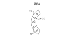
- FIG. 8A is a partial radial cross-sectional view of a rotor according to a fifth embodiment of the present invention
- FIG. 8B is another partial radial cross-sectional view of a rotor according to a fifth embodiment of the present invention
- FIG. 8C is a partial radial cross-sectional view of a rotor according to a fifth embodiment of the present invention
- FIG. 3 is a partial axial sectional view of a rotor according to a fifth embodiment of the present invention.
- a plurality of pin holes 12 are formed at equal intervals in the circumferential direction of the magnetic plate 11A.
- a plurality of pin holes 12' are formed at equal intervals in the circumferential direction of the magnetic plate 11B.
- the plurality of pin holes 12' in FIG. 8B are arranged radially outward than the plurality of pin holes 12 shown in FIG. 8A.
- the cross section of the pin hole 12 in the fifth embodiment does not need to have two-fold symmetry, and the cross section of the pin hole 12 in the fifth embodiment may be circular.
- a plurality of magnetic plates 11B are arranged above and below the rotor 10.
- the plurality of magnetic plates 11A are arranged between the plurality of upper magnetic plates 11B and the plurality of lower magnetic plates 11B.
- a pin hole 12x having a stepped inner surface is formed.
- the curved portion 21 of the pin 20 will fit along the stepped portion of the pin hole 12x. That is, in the fifth embodiment, the positions of the plurality of through holes in each of the magnetic plates 11A and 11B are made different from each other depending on the curved portion 21 of the pin 20. With such a configuration, the frictional resistance when press-fitting the pin 20 into the pin hole 12x is reduced, and the pin 20 can be press-fitted easily. Therefore, effects similar to those described above can be obtained.
- the number of magnetic plates 11B on the upper and lower sides of the rotor 10 and the number of the plurality of magnetic plates 11A are changed as appropriate depending on the shape of the curved portion 21 of the pin 20. Further, the number of magnetic plates 11B above or below the rotor 10 may be zero. Furthermore, it is within the scope of the fifth embodiment to use three or more types of magnetic plates with different positions of through holes so that a plurality of steps are formed.
- the pin hole 12 has a shape that matches/accommodates the curved portion 21 of the pin 20. Therefore, since the pin hole 12 has such a shape, when the pin 20 is press-fitted into the pin hole 12, the contact area between the pin 20 and the rotor 10 can be reduced, and the frictional resistance can be reduced. Therefore, the pin 20 can be easily press-fitted into the pin hole 12, and the plurality of magnetic plates 11 can be firmly connected. As a result, the production efficiency of the rotor 10 can be improved.
- the core in the embodiment described above may be applied to an electromagnetic device other than an electric motor, such as a core of a reactor or a transformer, and even such a case is within the scope of the present invention.
Abstract
A plurality of pin holes (12) are formed in an end surface of a core (10) of this electric motor. The core includes a plurality of pins (20) inserted into the respective plurality of pin holes. At least one of the pins includes a curved portion (21) at least partly curved relative to an axial direction of the pin. The pin hole into which said at least one pin is inserted is formed in such a manner as to conform to the curved portion.
Description
本発明の実施形態は、電動機のコアに関する。
Embodiments of the present invention relate to a core of an electric motor.
電動機としての電動機のコアは、ステータと、該ステータに対して回転するロータとを含んでいる(例えば、特開2010-259256号公報)。このような電動機のコアは、複数の磁性板、例えば鉄板、炭素鋼板、電磁鋼板をコアの軸線方向に積層することにより形成された積層体でありうる。
A core of an electric motor includes a stator and a rotor that rotates with respect to the stator (for example, Japanese Patent Application Publication No. 2010-259256). The core of such a motor may be a laminate formed by laminating a plurality of magnetic plates, such as iron plates, carbon steel plates, and electromagnetic steel plates, in the axial direction of the core.
複数の磁性板のそれぞれには、複数の貫通孔が形成されている。積層体としてのコアにおいては、隣接する磁性板における複数の貫通孔が互いに整列して複数のピン穴を形成する。従って、コアの内部には、複数のピン穴がコアの積層方向(コアの軸線方向)に延びることになる。そして、コアの端面から複数のピンを複数のピン穴にそれぞれ圧入し、それにより、複数の磁性板を互いに結合させ、堅固なコアを形成している。
A plurality of through holes are formed in each of the plurality of magnetic plates. In the core as a laminate, a plurality of through holes in adjacent magnetic plates are aligned with each other to form a plurality of pin holes. Therefore, inside the core, a plurality of pin holes extend in the stacking direction of the core (in the axial direction of the core). Then, a plurality of pins are press-fitted into the plurality of pin holes from the end face of the core, thereby bonding the plurality of magnetic plates to each other and forming a strong core.
ピンをピン穴に挿入するために、比較的大きな力が必要とされる。このため、ピンをピン穴に容易に圧入でき、且つ複数の磁性板を堅固に結合させることのできる、電動機のコアが臨まれている。
A relatively large force is required to insert the pin into the pin hole. For this reason, there is a need for an electric motor core in which a pin can be easily press-fitted into a pin hole and a plurality of magnetic plates can be firmly connected.
本開示の1番目の態様によれば、電動機のコアにおいて、前記コアの端面には複数のピン穴が形成されており、さらに、前記複数のピン穴のそれぞれに挿入される複数のピンを具備し、前記複数のピンのうちの少なくとも一つのピンは、該少なくとも一つのピンの軸線方向に対して少なくとも部分的に湾曲する湾曲部分を含んでおり、前記少なくとも一つのピンが挿入される前記複数のピン穴のうちの少なくとも一つのピン穴は前記少なくとも一つのピンの前記湾曲部分に適合するように形成されている、コアが提供される。
According to a first aspect of the present disclosure, in the core of an electric motor, a plurality of pin holes are formed in an end surface of the core, and further includes a plurality of pins inserted into each of the plurality of pin holes. At least one of the plurality of pins includes a curved portion that is at least partially curved with respect to the axial direction of the at least one pin, and the at least one pin is inserted into the plurality of pins. A core is provided, wherein at least one of the pin holes is configured to fit the curved portion of the at least one pin.
本発明の目的、特徴及び利点は、添付図面に関連した以下の実施形態の説明により一層明らかになろう。
The objects, features, and advantages of the present invention will become more apparent from the following description of the embodiments in conjunction with the accompanying drawings.
以下、添付図面を参照して本発明の実施の形態を説明する。全図面に渡り、対応する構成要素には共通の参照符号を付す。
図1は本発明の第一の実施形態に基づく電動機の断面図である。図1に示されるように、電動機1はステータ9と、ステータ9に回転可能に支持されたロータ10とを含んでいる。ステータ9の内周面には第一軸受7および第二軸受8が配置されている。そして、ロータ9を貫通する軸部5が第一軸受7および第二軸受8によりステータ9に回転可能に支持されている。なお、ステータ9の一端には、軸部5の回転数などを検出する検出器6が取付けられている。 Embodiments of the present invention will be described below with reference to the accompanying drawings. Corresponding components are given common reference numerals throughout the drawings.
FIG. 1 is a sectional view of an electric motor according to a first embodiment of the present invention. As shown in FIG. 1, theelectric motor 1 includes a stator 9 and a rotor 10 rotatably supported by the stator 9. A first bearing 7 and a second bearing 8 are arranged on the inner peripheral surface of the stator 9. A shaft portion 5 passing through the rotor 9 is rotatably supported by the stator 9 by a first bearing 7 and a second bearing 8. Note that a detector 6 is attached to one end of the stator 9 to detect the rotational speed of the shaft portion 5 and the like.
図1は本発明の第一の実施形態に基づく電動機の断面図である。図1に示されるように、電動機1はステータ9と、ステータ9に回転可能に支持されたロータ10とを含んでいる。ステータ9の内周面には第一軸受7および第二軸受8が配置されている。そして、ロータ9を貫通する軸部5が第一軸受7および第二軸受8によりステータ9に回転可能に支持されている。なお、ステータ9の一端には、軸部5の回転数などを検出する検出器6が取付けられている。 Embodiments of the present invention will be described below with reference to the accompanying drawings. Corresponding components are given common reference numerals throughout the drawings.
FIG. 1 is a sectional view of an electric motor according to a first embodiment of the present invention. As shown in FIG. 1, the
本願明細書における「電動機のコア」として、電動機1のロータ10を用いて説明する。しかしながら、「電動機のコア」は電動機1のステータ9を含んでおり、以下の説明はステータ9としてのコアにも適用できることに留意されたい。
The rotor 10 of the electric motor 1 will be used as the "core of the electric motor" in this specification. However, it should be noted that the "core of the motor" includes the stator 9 of the motor 1 and that the following description also applies to the core as stator 9.
図2Aは図1に示されるロータの半径方向断面図であり、図2Bは図2Aの線A-A’に沿ってみたロータの軸線方向部分断面図である。図2Aから分かるように、ロータ10は環状であり、その中心には、軸部5(図2Aには示さない)が挿入されるべき孔が形成されている。また、図2Bから分かるように、ロータ10は、複数の同一形状の磁性板(コア板)11、例えば鉄板、炭素鋼板、電磁鋼板をロータ10の軸線方向に積層することにより形成されている。
2A is a radial cross-sectional view of the rotor shown in FIG. 1, and FIG. 2B is a partial axial cross-sectional view of the rotor taken along line A-A' in FIG. 2A. As can be seen from FIG. 2A, the rotor 10 is annular and has a hole formed in its center into which the shaft 5 (not shown in FIG. 2A) is inserted. Further, as can be seen from FIG. 2B, the rotor 10 is formed by laminating a plurality of magnetic plates (core plates) 11 having the same shape, such as iron plates, carbon steel plates, and electromagnetic steel plates in the axial direction of the rotor 10.
なお、第一の実施形態および後述する幾つかの実施形態においては、ロータ10およびステータ9は複数の磁性板11から形成されていなくてもよく、ロータ10およびステータ9がフェライトまたは圧粉鉄心などの磁性材料から作成された一体部材であってもよい。
In addition, in the first embodiment and some embodiments to be described later, the rotor 10 and the stator 9 do not need to be formed from a plurality of magnetic plates 11, and the rotor 10 and the stator 9 may be made of a ferrite core, a powdered iron core, or the like. It may be an integral member made from a magnetic material.
図2Aを参照すると、ロータ10には複数のピン穴12が周方向に等間隔で形成されている。図2Bを参照して分かるように、複数の磁性板11のそれぞれには(複数の)貫通孔が形成されている。複数の磁性板11を積層するときに、貫通孔は互いに整列して、前述したピン穴12を形成する。
Referring to FIG. 2A, a plurality of pin holes 12 are formed in the rotor 10 at equal intervals in the circumferential direction. As can be seen with reference to FIG. 2B, each of the plurality of magnetic plates 11 is formed with (a plurality of) through holes. When a plurality of magnetic plates 11 are stacked, the through holes are aligned with each other to form the pin holes 12 described above.
複数のピン穴12のそれぞれには、ピン20がロータ10の軸線方向に挿入されている。厳密にいえば、隣接する磁性板11を互いに締結する目的で、ピン20は、対応するピン穴12に圧入されている。
A pin 20 is inserted into each of the plurality of pin holes 12 in the axial direction of the rotor 10. Strictly speaking, the pins 20 are press-fitted into corresponding pin holes 12 for the purpose of fastening adjacent magnetic plates 11 to each other.
図2Bから分かるように、ピン20はその軸線方向に少なくとも部分的に湾曲する湾曲部分21を有する場合がある。そのような湾曲部分21はピン穴12の内壁に接触し、その結果、摩擦抵抗が増えてピン20をピン穴12に圧入するのが困難になる場合がある。
As can be seen from FIG. 2B, the pin 20 may have a curved portion 21 that is at least partially curved in its axial direction. Such a curved portion 21 contacts the inner wall of the pin hole 12, and as a result, frictional resistance increases and it may be difficult to press fit the pin 20 into the pin hole 12.
このため、第一の実施形態においては、複数のピン穴12のうちの少なくとも一つのピン穴12はピン20の湾曲部分21に適合するように形成されている。言い換えれば、ピン穴12はピン20の湾曲部分21を吸収するように形成されている。そのようなピン穴12は、例えばロータ10の半径方向におけるピン穴12の断面が楕円である。図2Bから分かるように、このような構成においては、ピン20とロータ10との間の接触面積が減り、ピン20をピン穴12に圧入するときの摩擦抵抗が低下する。従って、ピン20をピン穴12に容易に圧入でき、且つ複数の磁性板11を堅固に結合させることが可能となる。その結果、ロータ10の生産効率を向上させられる。
Therefore, in the first embodiment, at least one pin hole 12 among the plurality of pin holes 12 is formed to fit the curved portion 21 of the pin 20. In other words, the pin hole 12 is formed to accommodate the curved portion 21 of the pin 20. For example, such a pin hole 12 has an elliptical cross section in the radial direction of the rotor 10. As can be seen from FIG. 2B, in such a configuration, the contact area between the pin 20 and the rotor 10 is reduced, and the frictional resistance when the pin 20 is press-fitted into the pin hole 12 is reduced. Therefore, the pin 20 can be easily press-fitted into the pin hole 12, and the plurality of magnetic plates 11 can be firmly connected. As a result, the production efficiency of the rotor 10 can be improved.
ところで、図4は断面がC字形状のピンおよび断面が環状のピンの斜視図である。図4の左方には、断面がC字形状のピン20が示されており、図4の右方には、断面が環状のピン20’が示されている。従前は、ピン20をピン穴12に容易に圧入するために、C字形状のピン20を使用することが多かったが、C字形状のピン20は比較的高価であるという欠点がある。
By the way, FIG. 4 is a perspective view of a pin with a C-shaped cross section and a pin with an annular cross section. A pin 20 with a C-shaped cross section is shown on the left side of FIG. 4, and a pin 20' with an annular cross section is shown on the right side of FIG. In the past, C-shaped pins 20 were often used in order to easily press-fit the pins 20 into the pin holes 12, but the C-shaped pins 20 had the disadvantage of being relatively expensive.
前述したように、第一の実施形態においては、ピン穴12がピン20の湾曲部分21に適合するように形成されているので、ピン20を比較的容易に圧入できる。このため、第一の実施形態においては、比較的高価なC字形状のピン20を必ずしも使用する必要はなく、比較的安価な環状のピン20’を使用することが可能となる。このため、ロータ10の製造費用を抑えられるのが分かるであろう。なお、当然のことながら、第一の実施形態においても、C字形状のピン20を使用しても良い。
As described above, in the first embodiment, the pin hole 12 is formed to fit the curved portion 21 of the pin 20, so the pin 20 can be press-fitted relatively easily. Therefore, in the first embodiment, it is not necessary to use the relatively expensive C-shaped pin 20, and it is possible to use the relatively inexpensive annular pin 20'. As can be seen, the manufacturing cost of the rotor 10 can therefore be reduced. Note that, as a matter of course, the C-shaped pin 20 may also be used in the first embodiment.
図3Aから図3Dはピン穴の変形例をそれぞれ示す図である。図3Aには、図2A等と同様に断面が楕円形のピン穴12aが示されている。図3Aにおいては、ピン穴12aの断面について、該断面の中心と断面の縁部とを最長距離で結ぶ最長線分R1aと、断面の中心と断面の縁部とを最短距離で結ぶ最短線分R2aとを定義できる。図3Aにおいては、最長線分R1aおよび最短線分R2aは楕円の長軸および短軸にそれぞれ相当する。
FIGS. 3A to 3D are diagrams showing modified examples of pin holes. FIG. 3A shows a pin hole 12a having an oval cross section, similar to FIG. 2A and the like. In FIG. 3A, regarding the cross section of the pin hole 12a, the longest line segment R1a that connects the center of the cross section and the edge of the cross section with the longest distance, and the shortest line segment that connects the center of the cross section and the edge of the cross section with the shortest distance. R2a can be defined. In FIG. 3A, the longest line segment R1a and the shortest line segment R2a correspond to the long axis and short axis of the ellipse, respectively.
図3Bには、断面が長方形のピン穴12bが示されている。同様にして、ピン穴12bの断面について、該断面の中心と断面の縁部とを最長距離で結ぶ最長線分R1bと、断面の中心と断面の縁部とを最短距離で結ぶ最短線分R2bとを定義できる。
FIG. 3B shows a pin hole 12b with a rectangular cross section. Similarly, regarding the cross section of the pin hole 12b, the longest line segment R1b that connects the center of the cross section and the edge of the cross section with the longest distance, and the shortest line segment R2b that connects the center of the cross section and the edge of the cross section with the shortest distance. can be defined.
さらに、図3Cには、断面が長円形のピン穴12cが示されており、図3Dには、断面が細長六角形のピン穴12dが示されている。同様にして、ピン穴12cの断面について、該断面の中心と断面の縁部とを最長距離で結ぶ最長線分R1cと、断面の中心と断面の縁部とを最短距離で結ぶ最短線分R2cとを定義できる。さらに、ピン穴12dの断面について、該断面の中心と断面の縁部とを最長距離で結ぶ最長線分R1dと、断面の中心と断面の縁部とを最短距離で結ぶ最短線分R2dとを定義できる。
Further, FIG. 3C shows a pin hole 12c with an oval cross section, and FIG. 3D shows a pin hole 12d with an elongated hexagonal cross section. Similarly, regarding the cross section of the pin hole 12c, the longest line segment R1c that connects the center of the cross section and the edge of the cross section with the longest distance, and the shortest line segment R2c that connects the center of the cross section and the edge of the cross section with the shortest distance. can be defined. Furthermore, regarding the cross section of the pin hole 12d, the longest line segment R1d that connects the center of the cross section and the edge of the cross section with the longest distance, and the shortest line segment R2d that connects the center of the cross section and the edge of the cross section with the shortest distance. Can be defined.
ところで、一つの点を中心に、或る図形を360/n度だけ回転させたとき(nは2以上の整数)、元の図形に完全に重なり合う性質を有する図形は、「n回対称性」を有する、と一般に言う。
By the way, a figure that has the property of completely overlapping the original figure when it is rotated by 360/n degrees around a single point (n is an integer of 2 or more) has "n-fold symmetry". It is generally said to have.
図3Aから図3Dより分かるように、ピン穴12a~12dは、それぞれの断面の中心回りに180°回転させたときに、元のピン穴12a~12dに重なり合う。従って、ピン穴12a~12dは「2回対称性」を有する。
As can be seen from FIGS. 3A to 3D, the pin holes 12a to 12d overlap the original pin holes 12a to 12d when rotated by 180 degrees around the center of each cross section. Therefore, the pin holes 12a to 12d have "two-fold symmetry."
ピン20の直径はピン穴12a~12dの最短線分R2a~R2dに概ね等しい。このため、ピン20の湾曲部分21がピン穴12a~12dの最長線分R1a~R1d側縁部に向かうように、または湾曲部分21が最長線分R1a~R1d上に位置するように、ピン20をピン穴12に対して位置決めするのが好ましい。そして、そのように位置決めした後で、または位置決めしながら、ピン20をピン穴12a~12dに圧入する。
The diameter of the pin 20 is approximately equal to the shortest line segment R2a to R2d of the pin holes 12a to 12d. Therefore, the pin 20 is arranged so that the curved portion 21 of the pin 20 is directed toward the side edge of the longest line segment R1a to R1d of the pin holes 12a to 12d, or so that the curved portion 21 is located on the longest line segment R1a to R1d. is preferably positioned relative to the pin hole 12. After or while positioning, the pins 20 are press-fitted into the pin holes 12a to 12d.
この場合には、ピン20の湾曲部分21が最長線分R1a~R1d側縁部に接触しないか、または殆ど接触しない。従って、ピン20をピン穴12に圧入するときの摩擦抵抗が低下して、ピン20を容易に圧入できる。このため、前述したのと同様な効果を得ることができる。なお、ピン穴12の断面が、2回対称性を有する他の形状、例えば細長多角形などであってもよい。このような場合には、ロータ10の製造費用を抑えられるのが分かるであろう。
In this case, the curved portion 21 of the pin 20 does not or hardly contacts the side edges of the longest line segments R1a to R1d. Therefore, the frictional resistance when press-fitting the pin 20 into the pin hole 12 is reduced, and the pin 20 can be press-fitted easily. Therefore, effects similar to those described above can be obtained. Note that the cross section of the pin hole 12 may have another shape having two-fold symmetry, such as an elongated polygon. In such a case, it will be understood that the manufacturing cost of the rotor 10 can be reduced.
図5Aおよび図5Bは本発明の第二の実施形態および第三の実施形態に基づくロータの半径方向部分断面図である。図5Aおよび図5Bにおいては、ロータ10が組込まれた電動機1が駆動している際の、ロータ10を部分的にのみ示している。これら図面においては、ロータ10の回転による遠心力FCがロータ10の半径方向に作用し、トルクの反作用による力FRがロータ10の周方向に作用している。そして、楕円形の断面を有する複数のピン穴12がロータ10に形成されている。
FIGS. 5A and 5B are partial radial cross-sectional views of rotors according to the second and third embodiments of the present invention. In FIGS. 5A and 5B, only a portion of the rotor 10 is shown when the electric motor 1 incorporating the rotor 10 is being driven. In these drawings, centrifugal force FC due to rotation of rotor 10 acts in the radial direction of rotor 10, and force FR due to torque reaction acts in the circumferential direction of rotor 10. A plurality of pin holes 12 having an oval cross section are formed in the rotor 10.
図5Aに示される第二の実施形態においては、遠心力FCは反作用による力FRよりも小さいものとする。つまり、第二の実施形態における電動機1は例えば大トルクのモータである。このような電動機1においては、図5Aに示されるように、ピン穴12の最長線分R1a(図3A等を参照)がロータ10の半径方向に延びるように、ピン穴12を形成するのが好ましい。
In the second embodiment shown in FIG. 5A, it is assumed that the centrifugal force FC is smaller than the reaction force FR. That is, the electric motor 1 in the second embodiment is, for example, a large torque motor. In such an electric motor 1, as shown in FIG. 5A, it is preferable to form the pin hole 12 so that the longest line segment R1a (see FIG. 3A, etc.) of the pin hole 12 extends in the radial direction of the rotor 10. preferable.
遠心力FCが反作用による力FRよりも小さい場合には、電動機1の駆動時にピン20がロータ10の周方向に移動して、複数の磁性板11の間の結合が不十分になる可能性がある。しかしながら、第二の実施形態においては、ピン20は、ロータ10の周方向において隙間を有することなしにピン穴12に接触することになる。このため、第二の実施形態においては、電動機1の駆動時であってもピン20が周方向に移動せず、その結果、電動機1を安定して駆動させられる。
If the centrifugal force FC is smaller than the reaction force FR, the pin 20 may move in the circumferential direction of the rotor 10 when the electric motor 1 is driven, and the coupling between the plurality of magnetic plates 11 may become insufficient. be. However, in the second embodiment, the pin 20 comes into contact with the pin hole 12 without any gap in the circumferential direction of the rotor 10. Therefore, in the second embodiment, the pin 20 does not move in the circumferential direction even when the electric motor 1 is driven, and as a result, the electric motor 1 can be driven stably.
図5Bに示される第三の実施形態においては、遠心力FCは反作用による力FRよりも大きいものとする。つまり、第三の実施形態における電動機1は例えば高速回転型のモータである。このような電動機1においては、図5Bに示されるように、ピン穴12の最長線分R1a(図3A等を参照)がロータ10の周方向に延びるように、ピン穴12を形成するのが好ましい。
In the third embodiment shown in FIG. 5B, the centrifugal force FC is greater than the reaction force FR. That is, the electric motor 1 in the third embodiment is, for example, a high-speed rotation type motor. In such an electric motor 1, as shown in FIG. 5B, it is preferable to form the pin hole 12 so that the longest line segment R1a (see FIG. 3A, etc.) of the pin hole 12 extends in the circumferential direction of the rotor 10. preferable.
遠心力FCが反作用による力FRよりも大きい場合には、電動機1の駆動時にピン20がロータ10の半径方向に移動して、複数の磁性板11の間の結合が不十分になる可能性がある。しかしながら、第三の実施形態においては、ピン20は、ロータ10の半径方向において隙間を有することなしにピン穴12に接触することになる。このため、第三の実施形態においては、電動機1の駆動時であってもピン20が半径方向に移動せず、その結果、電動機1を安定して駆動させられる。
If the centrifugal force FC is larger than the reaction force FR, there is a possibility that the pin 20 will move in the radial direction of the rotor 10 when the electric motor 1 is driven, resulting in insufficient coupling between the plurality of magnetic plates 11. be. However, in the third embodiment, the pin 20 contacts the pin hole 12 without any gap in the radial direction of the rotor 10. Therefore, in the third embodiment, the pin 20 does not move in the radial direction even when the electric motor 1 is driven, and as a result, the electric motor 1 can be driven stably.
図6は本発明の第四の実施形態に基づくロータの半径方向部分断面図であり、図5Aおよび図5Bと同様の図である。第四の実施形態においては、遠心力FCと反作用による力FRとが互いに概ね等しいものとする。図6においては、複数のピン穴12e、12f、12g、12h、12iがロータ10の周方向に等間隔で形成されている。図6においては、ピン穴12e、12g、12iは、ロータ10の半径方向に対して時計回りに傾斜しており、ピン穴12f、12hはロータ10の半径方向に対して反時計回りに傾斜している。言い換えれば、図6においては、時計回りに傾斜したピン穴12e、12g、12iと、反時計回りに傾斜したピン穴12f、12hとが交互に配置されている。
FIG. 6 is a partial radial cross-sectional view of a rotor according to a fourth embodiment of the present invention, and is a view similar to FIGS. 5A and 5B. In the fourth embodiment, it is assumed that the centrifugal force FC and the reaction force FR are approximately equal to each other. In FIG. 6, a plurality of pin holes 12e, 12f, 12g, 12h, and 12i are formed at equal intervals in the circumferential direction of the rotor 10. In FIG. 6, the pin holes 12e, 12g, 12i are inclined clockwise with respect to the radial direction of the rotor 10, and the pin holes 12f, 12h are inclined counterclockwise with respect to the radial direction of the rotor 10. ing. In other words, in FIG. 6, clockwise inclined pin holes 12e, 12g, 12i and counterclockwise inclined pin holes 12f, 12h are arranged alternately.
このような構成においては、電動機1の駆動時において、ピン20がロータ10の半径方向にも周方向にも移動せず、その結果、電動機1を安定して駆動させられるのが分かるであろう。
It will be seen that in such a configuration, when the electric motor 1 is driven, the pin 20 does not move in either the radial direction or the circumferential direction of the rotor 10, and as a result, the electric motor 1 can be driven stably. .
また、図6においてピン穴12hがロータ10の半径方向に対して反時計回りに傾斜する角度A1はピン穴12iがロータ10の半径方向に対して時計回りに傾斜する角度A2に概ね等しいのが好ましい。他のピン穴の反時計回りまたは時計回りに傾斜する角度も同様である。この場合には、電動機1をさらに安定して駆動させられる。
Further, in FIG. 6, the angle A1 at which the pin hole 12h is inclined counterclockwise with respect to the radial direction of the rotor 10 is approximately equal to the angle A2 at which the pin hole 12i is inclined clockwise with respect to the radial direction of the rotor 10. preferable. The same applies to the counterclockwise or clockwise inclined angles of other pin holes. In this case, the electric motor 1 can be driven more stably.
さらに、図7Aは第四の実施形態における他の変形例に基づくロータの半径方向部分断面図であり、図7Bは第四の実施形態におけるさらに他の変形例に基づくロータの半径方向部分断面図である。図7Aおよび図7Bは図5Aおよび図5Bと同様の図であり、これら図面においても、遠心力FCと反作用による力FRとが互いに概ね等しいものとする。
Furthermore, FIG. 7A is a partial radial sectional view of a rotor based on another modification of the fourth embodiment, and FIG. 7B is a partial radial sectional view of a rotor based on still another modification of the fourth embodiment. It is. 7A and 7B are similar to FIGS. 5A and 5B, and in these drawings as well, it is assumed that the centrifugal force FC and the reaction force FR are approximately equal to each other.
図7Aにおいては複数のピン穴12j、12k、12l、12m、12n、12o、12pがロータ10の周方向に等間隔で形成されている。図示されるように、ピン穴12j、12m、12nはロータ10の半径方向に対して時計回りに傾斜している。さらに、ピン穴12k、12l、12o、12pはロータ10の半径方向に対して反時計回りに傾斜している。従って、反時計回りに傾斜したピン穴12k、12l、12o、12pと、時計回りに傾斜したピン穴12j、12m、12nとが二つおきに配置されている。このような場合であっても、前述したのと同様な効果が得られるのは明らかであろう。また、反時計回りに傾斜したピン穴と、時計回りに傾斜したピン穴とが、複数個(三つ以上)おきに配置されていてもよい。
In FIG. 7A, a plurality of pin holes 12j, 12k, 12l, 12m, 12n, 12o, and 12p are formed at equal intervals in the circumferential direction of the rotor 10. As illustrated, the pin holes 12j, 12m, and 12n are inclined clockwise with respect to the radial direction of the rotor 10. Furthermore, the pin holes 12k, 12l, 12o, and 12p are inclined counterclockwise with respect to the radial direction of the rotor 10. Therefore, every second pin hole 12k, 12l, 12o, 12p tilted counterclockwise and pin hole 12j, 12m, 12n tilted clockwise are arranged. It is clear that even in such a case, the same effects as described above can be obtained. Further, a counterclockwise inclined pin hole and a clockwise inclined pin hole may be arranged every plurality (three or more).
図7Bにおいては、複数のピン穴12q、12r、12s、12t、12u、12v、12wがロータ10の周方向に等間隔で形成されている。図示されるように、ピン穴12s、12wはロータ10の半径方向に対して時計回りに傾斜している。さらに、ピン穴12q、12r、12t、12u、12vはロータ10の半径方向に対して反時計回りに傾斜している。従って、反時計回りに傾斜したピン穴12q、12r、12t、12u、12vと、時計回りに傾斜したピン穴12s、12wとがランダムに配置されている。言い換えれば、複数のピン穴のうちの一部分のピン穴は反時計回りに傾斜していて、残りのピン穴は時計回りに傾斜している。そして、反時計回りに傾斜したピン穴の数と、時計回りに傾斜したピン穴の数とは互いに概ね等しいのが好ましい。このような構成においても、前述したのと同様な効果が得られるのは明らかであろう。
In FIG. 7B, a plurality of pin holes 12q, 12r, 12s, 12t, 12u, 12v, and 12w are formed at equal intervals in the circumferential direction of the rotor 10. As illustrated, the pin holes 12s and 12w are inclined clockwise with respect to the radial direction of the rotor 10. Furthermore, the pin holes 12q, 12r, 12t, 12u, and 12v are inclined counterclockwise with respect to the radial direction of the rotor 10. Therefore, the counterclockwise inclined pin holes 12q, 12r, 12t, 12u, and 12v and the clockwise inclined pin holes 12s and 12w are randomly arranged. In other words, some of the pin holes are tilted counterclockwise, and the remaining pin holes are tilted clockwise. Preferably, the number of pin holes tilted counterclockwise and the number of pin holes tilted clockwise are approximately equal to each other. It is obvious that the same effects as described above can be obtained with such a configuration as well.
図8Aは本発明の第五の実施形態に基づくロータの半径方向部分断面図であり、図8Bは本発明の第五の実施形態に基づくロータの他の半径方向部分断面図であり、図8Cは本発明の第五の実施形態に基づくロータの軸線方向部分断面図である。
8A is a partial radial cross-sectional view of a rotor according to a fifth embodiment of the present invention, FIG. 8B is another partial radial cross-sectional view of a rotor according to a fifth embodiment of the present invention, and FIG. 8C is a partial radial cross-sectional view of a rotor according to a fifth embodiment of the present invention. FIG. 3 is a partial axial sectional view of a rotor according to a fifth embodiment of the present invention.
図8Aにおいては複数のピン穴12が磁性板11Aの周方向に等間隔で形成されている。図8Bにおいても複数のピン穴12’が磁性板11Bの周方向に等間隔で形成されている。しかしながら、図8Bにおける複数のピン穴12’は、図8Aに示される複数のピン穴12よりも、半径方向外側に配置されている。なお、第五の実施形態におけるピン穴12の断面は2回対称性を有する必要はなく、第五の実施形態におけるピン穴12の断面は円形であってもよい。
In FIG. 8A, a plurality of pin holes 12 are formed at equal intervals in the circumferential direction of the magnetic plate 11A. Also in FIG. 8B, a plurality of pin holes 12' are formed at equal intervals in the circumferential direction of the magnetic plate 11B. However, the plurality of pin holes 12' in FIG. 8B are arranged radially outward than the plurality of pin holes 12 shown in FIG. 8A. Note that the cross section of the pin hole 12 in the fifth embodiment does not need to have two-fold symmetry, and the cross section of the pin hole 12 in the fifth embodiment may be circular.
そして、図8Cに示されるように、複数の磁性板11Bがロータ10の上方および下方に配置されている。そして、複数の磁性板11Aが、上方側の複数の磁性板11Bと、下方側の複数の磁性板11Bとの間に配置されている。その結果、段差の付いた内面を有するピン穴12xが形成される。
As shown in FIG. 8C, a plurality of magnetic plates 11B are arranged above and below the rotor 10. The plurality of magnetic plates 11A are arranged between the plurality of upper magnetic plates 11B and the plurality of lower magnetic plates 11B. As a result, a pin hole 12x having a stepped inner surface is formed.
図8Cに示されるようにピン20が略C字形状に湾曲している場合には、ピン20の湾曲部分21が、ピン穴12xの段差部分に沿って適合するようになる。つまり、第五の実施形態においては、磁性板11A、11Bのそれぞれにおける複数の貫通孔の位置は、ピン20の湾曲部分21に応じて、互いに異ならせている。このような構成であるので、従って、ピン20をピン穴12xに圧入するときの摩擦抵抗が低下して、ピン20を容易に圧入できる。このため、前述したのと同様な効果を得ることができる。
If the pin 20 is curved in a substantially C-shape as shown in FIG. 8C, the curved portion 21 of the pin 20 will fit along the stepped portion of the pin hole 12x. That is, in the fifth embodiment, the positions of the plurality of through holes in each of the magnetic plates 11A and 11B are made different from each other depending on the curved portion 21 of the pin 20. With such a configuration, the frictional resistance when press-fitting the pin 20 into the pin hole 12x is reduced, and the pin 20 can be press-fitted easily. Therefore, effects similar to those described above can be obtained.
なお、ロータ10の上方および下方側の磁性板11Bの数、ならびに複数の磁性板11Aの数は、ピン20の湾曲部分21の形状に応じて適宜変更されるものとする。また、ロータ10の上方または下方側の磁性板11Bの数がゼロであってもよい。さらに、複数の段差が形成されるように、貫通孔の位置が異なる3種以上の磁性板を使用することは、第五の実施形態の範囲に含まれる。
Note that the number of magnetic plates 11B on the upper and lower sides of the rotor 10 and the number of the plurality of magnetic plates 11A are changed as appropriate depending on the shape of the curved portion 21 of the pin 20. Further, the number of magnetic plates 11B above or below the rotor 10 may be zero. Furthermore, it is within the scope of the fifth embodiment to use three or more types of magnetic plates with different positions of through holes so that a plurality of steps are formed.
このように、本発明の全ての実施形態においては、ピン穴12がピン20の湾曲部分21に適合する形状/湾曲部分21を吸収する形状を有する。従って、このようなピン穴12であるために、ピン20をピン穴12に圧入するときに、ピン20とロータ10との間の接触面積を減らし、その摩擦抵抗を低下できる。従って、ピン20をピン穴12に容易に圧入でき、且つ複数の磁性板11を堅固に結合させることが可能となる。その結果、ロータ10の生産効率を向上させられる。
Thus, in all embodiments of the invention, the pin hole 12 has a shape that matches/accommodates the curved portion 21 of the pin 20. Therefore, since the pin hole 12 has such a shape, when the pin 20 is press-fitted into the pin hole 12, the contact area between the pin 20 and the rotor 10 can be reduced, and the frictional resistance can be reduced. Therefore, the pin 20 can be easily press-fitted into the pin hole 12, and the plurality of magnetic plates 11 can be firmly connected. As a result, the production efficiency of the rotor 10 can be improved.
また、前述した実施形態におけるコアを電動機以外の電磁機器、例えばリアクトルや変圧器のコアに適用してもよく、そのような場合であっても、本発明の範囲に含まれる。
Furthermore, the core in the embodiment described above may be applied to an electromagnetic device other than an electric motor, such as a core of a reactor or a transformer, and even such a case is within the scope of the present invention.
本開示の実施形態について詳述したが、本開示は上述した個々の実施形態に限定されるものではない。これらの実施形態は、発明の要旨を逸脱しない範囲で、または請求の範囲に記載された内容とその均等物から導き出される本発明の思想および趣旨を逸脱しない範囲で、種々の追加、置き換え、変更、部分的削除などが可能である。例えば、上述した実施形態において、各動作の順序や各処理の順序は、一例として示したものであり、これらに限定されるものではない。
Although the embodiments of the present disclosure have been described in detail, the present disclosure is not limited to the individual embodiments described above. These embodiments are subject to various additions, substitutions, and changes without departing from the gist of the invention or the spirit and spirit of the present invention derived from the contents described in the claims and equivalents thereof. , partial deletion, etc. are possible. For example, in the embodiments described above, the order of each operation and the order of each process are shown as examples, and are not limited to these.
1 電動機
5 軸部
7、8 軸受
9 ステータ(コア)
10 ロータ(コア)
11、11A、11B 磁性板(コア板)
12、12a~12x ピン穴
20、20’ ピン
21 湾曲部分
R1a~R1d 最長線分
R2a~R2d 最短線分 1Electric motor 5 Shaft part 7, 8 Bearing 9 Stator (core)
10 Rotor (core)
11, 11A, 11B Magnetic plate (core plate)
12, 12a to 12xPin hole 20, 20' Pin 21 Curved portion R1a to R1d Longest line segment R2a to R2d Shortest line segment
5 軸部
7、8 軸受
9 ステータ(コア)
10 ロータ(コア)
11、11A、11B 磁性板(コア板)
12、12a~12x ピン穴
20、20’ ピン
21 湾曲部分
R1a~R1d 最長線分
R2a~R2d 最短線分 1
10 Rotor (core)
11, 11A, 11B Magnetic plate (core plate)
12, 12a to 12x
Claims (10)
- 電動機のコアにおいて、
前記コアの端面には複数のピン穴が形成されており、
さらに、前記複数のピン穴のそれぞれに挿入される複数のピンを具備し、
前記複数のピンのうちの少なくとも一つのピンは、該少なくとも一つのピンの軸線方向に対して少なくとも部分的に湾曲する湾曲部分を含んでおり、
前記少なくとも一つのピンが挿入される前記複数のピン穴のうちの少なくとも一つのピン穴は前記少なくとも一つのピンの前記湾曲部分に適合するように形成されている、コア。 In the core of the electric motor,
A plurality of pin holes are formed in the end surface of the core,
further comprising a plurality of pins inserted into each of the plurality of pin holes,
At least one of the plurality of pins includes a curved portion that is at least partially curved with respect to the axial direction of the at least one pin,
At least one pin hole of the plurality of pin holes into which the at least one pin is inserted is formed to fit the curved portion of the at least one pin. - 前記コアの半径方向における前記少なくとも一つのピン穴の断面は、2回対称性を有する請求項1に記載のコア。 The core according to claim 1, wherein a cross section of the at least one pin hole in the radial direction of the core has two-fold symmetry.
- 前記断面は、楕円形、長円形、長方形、または細長六角形から選択される請求項2に記載のコア。 3. The core of claim 2, wherein the cross section is selected from an ellipse, an oval, a rectangle, or an elongated hexagon.
- 前記複数のピンのそれぞれの断面は環状である請求項1に記載のコア。 The core according to claim 1, wherein each of the plurality of pins has an annular cross section.
- 前記コアに作用すべき遠心力が前記コアに作用すべきトルクの反作用より小さい場合には、前記少なくとも一つのピン穴の断面の中心と該断面の縁部とを最長距離で結ぶ最長線分が前記コアの半径方向に配置されるようにした請求項2に記載のコア。 When the centrifugal force that should act on the core is smaller than the reaction of the torque that should act on the core, the longest line segment connecting the center of the cross section of the at least one pin hole and the edge of the cross section by the longest distance is 3. The core of claim 2, wherein the core is arranged in a radial direction of the core.
- 前記コアに作用すべき遠心力が前記コアに作用すべきトルクの反作用より大きい場合には、前記少なくとも一つのピン穴の断面の中心と該断面の縁部とを最長距離で結ぶ最長線分が前記コアの周方向に配置されるようにした請求項2に記載のコア。 When the centrifugal force that should act on the core is larger than the reaction of the torque that should act on the core, the longest line segment connecting the center of the cross section of the at least one pin hole and the edge of the cross section by the longest distance is The core according to claim 2, wherein the core is arranged in a circumferential direction of the core.
- 前記コアに作用すべき遠心力が前記コアに作用すべきトルクの反作用に等しい場合には、前記少なくとも一つのピン穴のうちの一部のピン穴の断面の中心と該断面の縁部とを最長距離で結ぶ最長線分は前記コアの半径方向に対して前記コアの時計回りに傾斜するよう配置されていると共に、前記少なくとも一つのピン穴のうちの残りのピン穴の最長部分は前記コアの半径方向に対して前記コアの反時計回りに傾斜するよう配置されている、請求項2に記載のコア。 When the centrifugal force that should act on the core is equal to the reaction of the torque that should act on the core, the center of the cross section of some of the at least one pin hole and the edge of the cross section. The longest line segment connecting the longest distance is arranged so as to be inclined clockwise in the core with respect to the radial direction of the core, and the longest portion of the remaining pin hole among the at least one pin hole The core according to claim 2, wherein the core is arranged to be inclined counterclockwise with respect to a radial direction of the core.
- 前記一部のピン穴の断面の前記最長線分が前記コアの半径方向に対して前記コアの時計回りに傾斜する傾斜角度は、前記残りのピン穴の前記最長線分が前記コアの半径方向に対して前記コアの反時計回りに傾斜する傾斜角度に等しいようにした、請求項7に記載のコア。 The inclination angle at which the longest line segment of the cross section of some of the pin holes is inclined in the clockwise direction of the core with respect to the radial direction of the core is such that the longest line segment of the remaining pin holes is inclined in the radial direction of the core. 8. The core of claim 7, wherein the inclination angle of the core is equal to the counterclockwise inclination angle of the core.
- 前記一部のピン穴と前記残りのピン穴とは、一つまたは複数個おきに配置されている、請求項7または8に記載のコア。 The core according to claim 7 or 8, wherein the part of the pin holes and the remaining pin holes are arranged every other pin hole or every other pin hole.
- 前記コアは、複数のコア板を積層することにより形成されており、
前記複数のコア板のそれぞれには、前記複数のピン穴に対応する複数の貫通孔が形成されており、
前記複数のコア板の前記複数の貫通孔は互いに整列して前記複数のピン穴を形成しており、
前記複数のコア板のそれぞれにおける前記複数の貫通孔の位置は、前記少なくとも一つのピンの前記湾曲部分に応じて、互いに異なるようにした、請求項1または2に記載のコア。 The core is formed by laminating a plurality of core plates,
A plurality of through holes corresponding to the plurality of pin holes are formed in each of the plurality of core plates,
The plurality of through holes of the plurality of core plates are aligned with each other to form the plurality of pin holes,
The core according to claim 1 or 2, wherein the positions of the plurality of through holes in each of the plurality of core plates are different from each other depending on the curved portion of the at least one pin.
Priority Applications (1)
| Application Number | Priority Date | Filing Date | Title |
|---|---|---|---|
| PCT/JP2022/022184 WO2023233538A1 (en) | 2022-05-31 | 2022-05-31 | Core of electric motor |
Applications Claiming Priority (1)
| Application Number | Priority Date | Filing Date | Title |
|---|---|---|---|
| PCT/JP2022/022184 WO2023233538A1 (en) | 2022-05-31 | 2022-05-31 | Core of electric motor |
Publications (1)
| Publication Number | Publication Date |
|---|---|
| WO2023233538A1 true WO2023233538A1 (en) | 2023-12-07 |
Family
ID=89026000
Family Applications (1)
| Application Number | Title | Priority Date | Filing Date |
|---|---|---|---|
| PCT/JP2022/022184 WO2023233538A1 (en) | 2022-05-31 | 2022-05-31 | Core of electric motor |
Country Status (1)
| Country | Link |
|---|---|
| WO (1) | WO2023233538A1 (en) |
Citations (3)
| Publication number | Priority date | Publication date | Assignee | Title |
|---|---|---|---|---|
| JPS54152103A (en) * | 1978-05-23 | 1979-11-30 | Fuji Electric Co Ltd | Lamination of stator core of revolving armature |
| JPS59226632A (en) * | 1983-06-02 | 1984-12-19 | Matsushita Electric Ind Co Ltd | Brushless motor |
| JPS63198372U (en) * | 1988-05-26 | 1988-12-21 |
-
2022
- 2022-05-31 WO PCT/JP2022/022184 patent/WO2023233538A1/en unknown
Patent Citations (3)
| Publication number | Priority date | Publication date | Assignee | Title |
|---|---|---|---|---|
| JPS54152103A (en) * | 1978-05-23 | 1979-11-30 | Fuji Electric Co Ltd | Lamination of stator core of revolving armature |
| JPS59226632A (en) * | 1983-06-02 | 1984-12-19 | Matsushita Electric Ind Co Ltd | Brushless motor |
| JPS63198372U (en) * | 1988-05-26 | 1988-12-21 |
Similar Documents
| Publication | Publication Date | Title |
|---|---|---|
| JP5118920B2 (en) | Rotor and rotating electric machine | |
| US8901796B2 (en) | Rotor having concentric deformation absorbing parts around shaft-fastening hole | |
| US7019428B2 (en) | Induction motor and rotor therefor | |
| JP2010011681A (en) | Rotor structure of permanent magnet rotating machine | |
| US20080296991A1 (en) | Synchronous reluctance motor | |
| US20150061443A1 (en) | Rotor and rotary electric machine having the same | |
| US10637310B2 (en) | Synchronous reluctance type rotary electric machine | |
| WO2018116738A1 (en) | Rotor for dynamo-electric machine, and dynamo-electric machine | |
| US11303172B2 (en) | Rotor for rotating electrical machine and rotor core support structure for rotating electrical machine | |
| US7772734B2 (en) | Rotor structure of rotating electric machine | |
| JP6601169B2 (en) | Rotating electric machine | |
| US20170093233A1 (en) | Brushless Motor | |
| US20170093262A1 (en) | Brushless Motor | |
| WO2023233538A1 (en) | Core of electric motor | |
| JP2017093059A (en) | Rotary electric machine | |
| US11462962B2 (en) | Rotor for dynamo-electric machine, and dynamo-electric machine | |
| US20200227963A1 (en) | Rotor core of rotating electrical machine | |
| JP4056725B2 (en) | Turbo molecular pump disc | |
| US9106116B2 (en) | Rotor of rotating electrical machine | |
| US20170093264A1 (en) | Brushless Motor | |
| US20170093259A1 (en) | Brushless Motor | |
| JP2005051826A (en) | Fixed structure of permanent magnet in rotor of rotating electric machine | |
| JP5025258B2 (en) | Rotating electrical machine rotor | |
| JP2018189199A (en) | Stator | |
| JP4244325B2 (en) | Rotating electrical machine rotor |
Legal Events
| Date | Code | Title | Description |
|---|---|---|---|
| 121 | Ep: the epo has been informed by wipo that ep was designated in this application |
Ref document number: 22944825 Country of ref document: EP Kind code of ref document: A1 |