WO2023228995A1 - ポンプ装置のドライアップ方法、クールダウン方法、およびホットアップ方法 - Google Patents
ポンプ装置のドライアップ方法、クールダウン方法、およびホットアップ方法 Download PDFInfo
- Publication number
- WO2023228995A1 WO2023228995A1 PCT/JP2023/019444 JP2023019444W WO2023228995A1 WO 2023228995 A1 WO2023228995 A1 WO 2023228995A1 JP 2023019444 W JP2023019444 W JP 2023019444W WO 2023228995 A1 WO2023228995 A1 WO 2023228995A1
- Authority
- WO
- WIPO (PCT)
- Prior art keywords
- flow path
- pump
- gas
- suction
- submersible pump
- Prior art date
- Legal status (The legal status is an assumption and is not a legal conclusion. Google has not performed a legal analysis and makes no representation as to the accuracy of the status listed.)
- Ceased
Links
Images












Classifications
-
- F—MECHANICAL ENGINEERING; LIGHTING; HEATING; WEAPONS; BLASTING
- F04—POSITIVE - DISPLACEMENT MACHINES FOR LIQUIDS; PUMPS FOR LIQUIDS OR ELASTIC FLUIDS
- F04D—NON-POSITIVE-DISPLACEMENT PUMPS
- F04D29/00—Details, component parts, or accessories
- F04D29/58—Cooling; Heating; Diminishing heat transfer
- F04D29/586—Cooling; Heating; Diminishing heat transfer specially adapted for liquid pumps
- F04D29/588—Cooling; Heating; Diminishing heat transfer specially adapted for liquid pumps cooling or heating the machine
-
- F—MECHANICAL ENGINEERING; LIGHTING; HEATING; WEAPONS; BLASTING
- F04—POSITIVE - DISPLACEMENT MACHINES FOR LIQUIDS; PUMPS FOR LIQUIDS OR ELASTIC FLUIDS
- F04D—NON-POSITIVE-DISPLACEMENT PUMPS
- F04D15/00—Control, e.g. regulation, of pumps, pumping installations or systems
- F04D15/0005—Control, e.g. regulation, of pumps, pumping installations or systems by using valves
-
- F—MECHANICAL ENGINEERING; LIGHTING; HEATING; WEAPONS; BLASTING
- F04—POSITIVE - DISPLACEMENT MACHINES FOR LIQUIDS; PUMPS FOR LIQUIDS OR ELASTIC FLUIDS
- F04D—NON-POSITIVE-DISPLACEMENT PUMPS
- F04D13/00—Pumping installations or systems
- F04D13/02—Units comprising pumps and their driving means
- F04D13/06—Units comprising pumps and their driving means the pump being electrically driven
- F04D13/08—Units comprising pumps and their driving means the pump being electrically driven for submerged use
-
- F—MECHANICAL ENGINEERING; LIGHTING; HEATING; WEAPONS; BLASTING
- F04—POSITIVE - DISPLACEMENT MACHINES FOR LIQUIDS; PUMPS FOR LIQUIDS OR ELASTIC FLUIDS
- F04D—NON-POSITIVE-DISPLACEMENT PUMPS
- F04D13/00—Pumping installations or systems
- F04D13/02—Units comprising pumps and their driving means
- F04D13/06—Units comprising pumps and their driving means the pump being electrically driven
- F04D13/08—Units comprising pumps and their driving means the pump being electrically driven for submerged use
- F04D13/086—Units comprising pumps and their driving means the pump being electrically driven for submerged use the pump and drive motor are both submerged
-
- F—MECHANICAL ENGINEERING; LIGHTING; HEATING; WEAPONS; BLASTING
- F04—POSITIVE - DISPLACEMENT MACHINES FOR LIQUIDS; PUMPS FOR LIQUIDS OR ELASTIC FLUIDS
- F04D—NON-POSITIVE-DISPLACEMENT PUMPS
- F04D13/00—Pumping installations or systems
- F04D13/12—Combinations of two or more pumps
- F04D13/14—Combinations of two or more pumps the pumps being all of centrifugal type
-
- F—MECHANICAL ENGINEERING; LIGHTING; HEATING; WEAPONS; BLASTING
- F04—POSITIVE - DISPLACEMENT MACHINES FOR LIQUIDS; PUMPS FOR LIQUIDS OR ELASTIC FLUIDS
- F04D—NON-POSITIVE-DISPLACEMENT PUMPS
- F04D15/00—Control, e.g. regulation, of pumps, pumping installations or systems
- F04D15/0072—Installation or systems with two or more pumps, wherein the flow path through the stages can be changed, e.g. series-parallel
-
- F—MECHANICAL ENGINEERING; LIGHTING; HEATING; WEAPONS; BLASTING
- F04—POSITIVE - DISPLACEMENT MACHINES FOR LIQUIDS; PUMPS FOR LIQUIDS OR ELASTIC FLUIDS
- F04D—NON-POSITIVE-DISPLACEMENT PUMPS
- F04D15/00—Control, e.g. regulation, of pumps, pumping installations or systems
- F04D15/02—Stopping of pumps, or operating valves, on occurrence of unwanted conditions
-
- F—MECHANICAL ENGINEERING; LIGHTING; HEATING; WEAPONS; BLASTING
- F04—POSITIVE - DISPLACEMENT MACHINES FOR LIQUIDS; PUMPS FOR LIQUIDS OR ELASTIC FLUIDS
- F04D—NON-POSITIVE-DISPLACEMENT PUMPS
- F04D29/00—Details, component parts, or accessories
- F04D29/58—Cooling; Heating; Diminishing heat transfer
- F04D29/586—Cooling; Heating; Diminishing heat transfer specially adapted for liquid pumps
- F04D29/5886—Cooling; Heating; Diminishing heat transfer specially adapted for liquid pumps cooling by injection
-
- F—MECHANICAL ENGINEERING; LIGHTING; HEATING; WEAPONS; BLASTING
- F04—POSITIVE - DISPLACEMENT MACHINES FOR LIQUIDS; PUMPS FOR LIQUIDS OR ELASTIC FLUIDS
- F04D—NON-POSITIVE-DISPLACEMENT PUMPS
- F04D7/00—Pumps adapted for handling specific fluids, e.g. by selection of specific materials for pumps or pump parts
- F04D7/02—Pumps adapted for handling specific fluids, e.g. by selection of specific materials for pumps or pump parts of centrifugal type
-
- F—MECHANICAL ENGINEERING; LIGHTING; HEATING; WEAPONS; BLASTING
- F04—POSITIVE - DISPLACEMENT MACHINES FOR LIQUIDS; PUMPS FOR LIQUIDS OR ELASTIC FLUIDS
- F04D—NON-POSITIVE-DISPLACEMENT PUMPS
- F04D9/00—Priming; Preventing vapour lock
- F04D9/004—Priming of not self-priming pumps
- F04D9/005—Priming of not self-priming pumps by adducting or recycling liquid
-
- F—MECHANICAL ENGINEERING; LIGHTING; HEATING; WEAPONS; BLASTING
- F04—POSITIVE - DISPLACEMENT MACHINES FOR LIQUIDS; PUMPS FOR LIQUIDS OR ELASTIC FLUIDS
- F04D—NON-POSITIVE-DISPLACEMENT PUMPS
- F04D9/00—Priming; Preventing vapour lock
- F04D9/004—Priming of not self-priming pumps
- F04D9/006—Priming of not self-priming pumps by venting gas or using gas valves
-
- F—MECHANICAL ENGINEERING; LIGHTING; HEATING; WEAPONS; BLASTING
- F17—STORING OR DISTRIBUTING GASES OR LIQUIDS
- F17C—VESSELS FOR CONTAINING OR STORING COMPRESSED, LIQUEFIED OR SOLIDIFIED GASES; FIXED-CAPACITY GAS-HOLDERS; FILLING VESSELS WITH, OR DISCHARGING FROM VESSELS, COMPRESSED, LIQUEFIED, OR SOLIDIFIED GASES
- F17C13/00—Details of vessels or of the filling or discharging of vessels
-
- F—MECHANICAL ENGINEERING; LIGHTING; HEATING; WEAPONS; BLASTING
- F04—POSITIVE - DISPLACEMENT MACHINES FOR LIQUIDS; PUMPS FOR LIQUIDS OR ELASTIC FLUIDS
- F04D—NON-POSITIVE-DISPLACEMENT PUMPS
- F04D1/00—Radial-flow pumps, e.g. centrifugal pumps; Helico-centrifugal pumps
- F04D1/06—Multi-stage pumps
-
- F—MECHANICAL ENGINEERING; LIGHTING; HEATING; WEAPONS; BLASTING
- F05—INDEXING SCHEMES RELATING TO ENGINES OR PUMPS IN VARIOUS SUBCLASSES OF CLASSES F01-F04
- F05D—INDEXING SCHEME FOR ASPECTS RELATING TO NON-POSITIVE-DISPLACEMENT MACHINES OR ENGINES, GAS-TURBINES OR JET-PROPULSION PLANTS
- F05D2260/00—Function
- F05D2260/60—Fluid transfer
- F05D2260/606—Bypassing the fluid
-
- F—MECHANICAL ENGINEERING; LIGHTING; HEATING; WEAPONS; BLASTING
- F05—INDEXING SCHEMES RELATING TO ENGINES OR PUMPS IN VARIOUS SUBCLASSES OF CLASSES F01-F04
- F05D—INDEXING SCHEME FOR ASPECTS RELATING TO NON-POSITIVE-DISPLACEMENT MACHINES OR ENGINES, GAS-TURBINES OR JET-PROPULSION PLANTS
- F05D2260/00—Function
- F05D2260/85—Starting
-
- F—MECHANICAL ENGINEERING; LIGHTING; HEATING; WEAPONS; BLASTING
- F17—STORING OR DISTRIBUTING GASES OR LIQUIDS
- F17C—VESSELS FOR CONTAINING OR STORING COMPRESSED, LIQUEFIED OR SOLIDIFIED GASES; FIXED-CAPACITY GAS-HOLDERS; FILLING VESSELS WITH, OR DISCHARGING FROM VESSELS, COMPRESSED, LIQUEFIED, OR SOLIDIFIED GASES
- F17C2223/00—Handled fluid before transfer, i.e. state of fluid when stored in the vessel or before transfer from the vessel
- F17C2223/01—Handled fluid before transfer, i.e. state of fluid when stored in the vessel or before transfer from the vessel characterised by the phase
- F17C2223/0146—Two-phase
- F17C2223/0153—Liquefied gas, e.g. LPG, GPL
Definitions
- the present invention provides a dry-up method, a cool-down method, and
- the present invention relates to a hot-up method, and particularly to a technique for drying, cooling, and warming a submersible pump while preventing the impeller of the submersible pump from rotating while the submersible pump is stopped.
- Natural gas is widely used for thermal power generation and as a chemical raw material. Furthermore, hydrogen is expected to be an energy source that does not generate carbon dioxide, which causes global warming. Applications of hydrogen as energy include fuel cells and turbine power generation. Natural gas and hydrogen are in a gaseous state at room temperature, so in order to store and transport them, natural gas and hydrogen are cooled and liquefied. Liquefied gases such as liquefied natural gas (LNG) and liquid hydrogen are once stored in liquefied gas storage tanks and then transported to power plants, factories, etc. by pumps.
- LNG liquefied natural gas
- liquid hydrogen are once stored in liquefied gas storage tanks and then transported to power plants, factories, etc. by pumps.
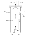
- FIG. 34 is a schematic diagram showing a conventional example of a pump device for pumping liquefied gas.
- Pump 500 is installed in a vertical suction vessel 505 connected to a liquefied gas storage tank (not shown) in which liquefied gas is stored.
- the liquefied gas is introduced into the suction container 505 through the suction port 501, and the suction container 505 is filled with the liquefied gas.
- the entire pump 500 is immersed in the liquefied gas. Therefore, pump 500 is a submersible pump that can be operated in liquefied gas.
- pump 500 When pump 500 is operated, liquefied gas is discharged by pump 500 through discharge port 502 .
- a portion of the liquefied gas in suction vessel 505 vaporizes to gas, which is exhausted from suction vessel 505 through vent line 503.
- a dry-up process in which air is removed from the suction container 505 using purge gas, and a cool-down process in which the pump 500 is cooled with liquefied gas are performed.
- the air present in the suction container 505 comes into contact with the ultra-low temperature liquefied gas
- the moisture in the air is cooled by the liquefied gas and solidifies, thereby inhibiting the rotational operation of the pump 500.
- the pump 500 is at room temperature when the pump 500 is started, when the ultra-low temperature liquefied gas comes into contact with the pump 500, the liquefied gas will vaporize. To prevent such an event, dry-up and cool-down are performed before pump 500 is operated.
- Dry-up is performed by injecting purge gas (e.g., nitrogen gas) into suction container 505, and cool-down is performed by injecting liquefied gas (e.g., liquefied natural gas) into suction container 505.
- purge gas e.g., nitrogen gas
- liquefied gas e.g., liquefied natural gas
- a hot-up process is performed in which the pump 500 is heated with a heating gas (for example, an inert gas at room temperature).
- a heating gas for example, an inert gas at room temperature.
- This hot-up is performed before the pump 500 contacts the surrounding air, so that components such as nitrogen in the air do not liquefy on the surface of the pump 500.
- hot-up is effective when the liquefied gas is liquid hydrogen. That is, when the pump 500 that has been immersed in liquid hydrogen is pulled up from the suction container 505, it is at an extremely low temperature equivalent to that of liquid hydrogen.
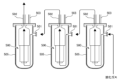
- multiple pump devices may be connected in series, as shown in FIG. 35.
- the liquefied gas is sequentially pressurized by the pumps 500 of the plurality of pump devices.
- the present invention provides a method of performing dry-up, cool-down, and hot-up on a submersible pump while preventing rotation of the impeller of the submersible pump while the submersible pump is not in operation.
- a dry-up method includes purging air from a plurality of pump devices including at least a first pump device and a second pump device connected in series, the method comprising and passing the purge gas through a first flow path switching device in the first suction container while bypassing a first submersible pump in the first suction container, and introducing the purge gas into the first flow path.
- the purge gas that has passed through the path switching device is introduced into the second suction container of the second pump device, and the purge gas is introduced while bypassing the second submersible pump in the second suction container.
- a dry-up method is provided, which includes passing through a second flow path switching device in the second suction container.
- each of the first flow path switching device and the second flow path switching device includes a flow path structure having a pump side flow path, a container side flow path, and an outflow flow path, and a flow path structure inside the flow path structure. and includes a valve body that selectively communicates the outflow channel with either the pump-side channel or the container-side channel, and the pump-side channel is connected to the corresponding submersible pump.
- the container-side flow path communicates with the interior of the corresponding suction container, and the outlet flow path communicates with the discharge port of the corresponding suction container.
- a dry-up method includes removing air from a suction vessel in which a submersible pump is housed, the method comprising: forming a vacuum within the suction vessel; and then introducing a purge gas into the suction vessel; A dry-up method is provided in which the purge gas is passed through a flow path switching device in the suction container while bypassing the submersible pump.
- a cool-down method for supplying liquefied gas to a plurality of pump devices including at least a first pump device and a second pump device connected in series, the method comprising: supplying liquefied gas to a first suction of the first pump device; introducing the liquefied gas into a container, passing the liquefied gas through a first flow path switching device in the first suction container while bypassing a first submersible pump in the first suction container; The liquefied gas that has passed through the first flow path switching device is introduced into a second suction container of the second pump device, and the liquefied gas bypasses a second submersible pump in the second suction container.
- a cool-down method is provided, in which the liquefied gas is passed through a second flow path switching device in the second suction container while causing the liquefied gas to pass through a second flow path switching device within the second suction container.
- each of the first flow path switching device and the second flow path switching device includes a flow path structure having a pump side flow path, a container side flow path, and an outflow flow path, and a flow path structure inside the flow path structure. and includes a valve body that selectively communicates the outflow channel with either the pump-side channel or the container-side channel, and the pump-side channel is connected to the corresponding submersible pump.
- the container-side flow path communicates with the interior of the corresponding suction container, and the outlet flow path communicates with the discharge port of the corresponding suction container.
- a cool-down method for cooling a submersible pump housed in a suction vessel comprising introducing liquefied gas into the suction vessel, and introducing the liquefied gas into the submersible pump while bypassing the submersible pump.
- a cool-down method is provided in which the liquefied gas is passed through a flow path switching device in the suction container.
- a hot-up method for supplying heated gas to a plurality of pump devices including at least a first pump device and a second pump device connected in series, the method comprising: a first flow path switching device in the first suction container; and introducing the heated gas that has passed through the first flow path switching device into a second suction container of the second pump device, and introduces the heated gas into a second suction container in the second suction container.
- a hot-up method is provided in which the heated gas is passed through a second flow switching device in the second suction vessel while bypassing the submersible pump.
- each of the first flow path switching device and the second flow path switching device includes a flow path structure having a pump side flow path, a container side flow path, and an outflow flow path, and a flow path structure inside the flow path structure. and includes a valve body that selectively communicates the outflow channel with either the pump-side channel or the container-side channel, and the pump-side channel is connected to the corresponding submersible pump.
- the container-side flow path communicates with the interior of the corresponding suction container, and the outlet flow path communicates with the discharge port of the corresponding suction container.
- a hot-up method for heating a submersible pump housed in a suction vessel comprising: introducing a heated gas into the suction vessel; A hot-up method is provided in which the heated gas is passed through a flow path switching device in the suction vessel while being bypassed.
- the flow path switching device can prevent gas (purge gas, warming gas) or liquefied gas introduced into the suction vessel during dry-up, cool-down, and hot-up from being introduced into the submersible pump. . Therefore, the impeller of the submersible pump that is not in operation does not rotate, and as a result, damage to sliding parts such as bearings of the submersible pump can be prevented.
- FIG. 1 shows an embodiment of a pump device for transporting liquefied gas
- FIG. FIG. 2 is a cross-sectional view showing an embodiment of a detailed configuration of a flow path switching device. This shows the state of the flow path switching device when the submersible pump is operating. It is a figure for explaining one embodiment of dry-up.
- FIG. 3 illustrates an embodiment of a process for creating a vacuum within a suction vessel.
- FIG. 3 is a diagram illustrating an embodiment of a process for introducing purge gas into a suction vessel.
- FIG. 2 is a diagram for explaining one embodiment of cool down. It is a figure for explaining other embodiments of cool down.
- FIG. 3 is a diagram for explaining an embodiment of hot-up.
- FIG. 1 is a schematic diagram showing an embodiment of a pump system including a plurality of pump devices connected in series.
- FIG. 12 is a diagram illustrating how dry-up is performed on the serially connected submersible pumps shown in FIG. 11.
- FIG. 3 illustrates an embodiment of a process for creating a vacuum within a plurality of suction vessels.
- FIG. 3 is a diagram illustrating an embodiment of a process for introducing purge gas into multiple suction vessels.
- FIG. 12 is a diagram illustrating an embodiment of a cool-down for cooling the serially connected submersible pumps shown in FIG. 11; FIG.
- FIG. 12 is a diagram illustrating another embodiment of a cool-down for cooling the serially connected submersible pumps shown in FIG. 11;
- FIG. 12 is a diagram illustrating an embodiment of a hot-up for heating the serially connected submersible pumps shown in FIG. 11;
- FIG. 12 is a diagram illustrating another embodiment of a hot-up for heating the series-connected submersible pumps shown in FIG. 11;
- FIG. 3 is a schematic diagram showing another embodiment of a pump system including a plurality of pump devices connected in series.
- FIG. 20 is a diagram showing how dry-up is performed on a plurality of pump devices of the pump system shown in FIG. 19;
- FIG. 3 illustrates an embodiment of a process for creating a vacuum within a plurality of suction vessels.
- FIG. 20 is a diagram showing how dry-up is performed on a plurality of pump devices of the pump system shown in FIG. 19;
- FIG. 3 illustrates an embodiment of a process for creating a vacuum within a plurality of su
- FIG. 3 is a diagram illustrating an embodiment of a process for introducing purge gas into multiple suction vessels.
- FIG. 20 is a diagram illustrating how the serially connected submersible pumps shown in FIG. 19 are cooled down.
- FIG. 20 is a diagram illustrating an embodiment in which a plurality of submersible pumps of the pump system shown in FIG. 19 are cooled down.
- 20 is a diagram illustrating an embodiment in which a plurality of pump devices of the pump system illustrated in FIG. 19 are heated up;
- FIG. 20 is a diagram showing another embodiment in which a plurality of pump devices of the pump system shown in FIG. 19 are heated up.
- FIG. FIG. 3 is a schematic diagram showing yet another embodiment of a pump system including a plurality of pump devices connected in series.
- FIG. 7 is a sectional view showing another embodiment of the flow path switching device. It is a sectional view showing still another embodiment of a flow path switching device. It is a sectional view showing other embodiments of a submersible pump. It is a sectional view showing still other embodiment of a submersible pump.
- FIG. 3 is a cross-sectional view showing an embodiment in which a gas vent valve is open. It is a sectional view showing one embodiment of a state where a gas vent valve is closed.
- FIG. 1 is a schematic diagram showing a conventional example of a pump device for pumping liquefied gas. It is a schematic diagram showing an example of a plurality of pump devices connected in series.
- FIG. 1 shows an embodiment of a pump device for transporting liquefied gas.
- Examples of the liquefied gas transferred by the pump device 100 shown in FIG. 1 include liquid hydrogen, liquid nitrogen, liquefied ammonia, liquefied natural gas, liquefied ethylene gas, and liquefied petroleum gas.
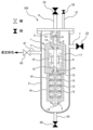
- the pump device 100 includes a submersible pump 1 for transferring liquefied gas, a suction container 2 in which the submersible pump 1 is housed, and a submersible pump that is not in operation.
- a flow path switching device 5 is provided to prevent rotation of the first impeller 15.
- the suction container 2 has a suction port 7 and a discharge port 8.
- the liquefied gas is introduced into the suction container 2 through the suction port 7, and the inside of the suction container 2 is filled with the liquefied gas.
- the submersible pump 1 is configured to be operable in liquefied gas.
- the submersible pump 1 includes an electric motor 11 having a motor rotor 9 and a motor stator 10, a rotating shaft 12 connected to the electric motor 11, a plurality of bearings 14 that rotatably supports the rotating shaft 12, and a plurality of bearings 14 fixed to the rotating shaft 12.
- the pump has an impeller 15 and a pump casing 16 that accommodates the impeller 15.
- the flow path switching device 5 is arranged within the suction container 2 . More specifically, the flow path switching device 5 is connected to both the discharge port 4 of the submersible pump 1 and the discharge port 8 of the suction container 2. The specific configuration of the flow path switching device 5 will be described later.
- the motor rotor 9 and the motor stator 10 are arranged within the motor housing 13.
- the electric motor 11 rotates the rotating shaft 12 and the impeller 15 together.
- the impeller 15 rotates, liquefied gas is sucked into the submersible pump 1 through the suction port 3 and discharged into the flow path switching device 5 through the discharge channel 17 and the discharge port 4. Furthermore, the liquefied gas passes through the flow path switching device 5 and is discharged through the discharge port 8 of the suction container 2 .
- a suction valve 22 is connected to the suction port 7, and a discharge valve 23 is connected to the discharge port 8.
- a drain line 25 is connected to the bottom of the suction container 2, and a drain valve 26 is connected to the drain line 25.
- the suction port 7 is provided on the side wall of the suction container 2 and is located at a higher position than the bottom of the suction container 2.
- the discharge port 8 is provided in the upper part of the suction container 2 and is located at a higher position than the suction port 7.
- a vent line 31 is connected to the upper part of the suction container 2.
- a portion of the liquefied gas is vaporized into gas due to the heat generated by the submersible pump 1, and this gas is discharged from the suction container 2 through the vent line 31.
- a vent valve 32 is connected to the vent line 31.
- this gas may be directed through vent line 31 to a gas treatment device (not shown).
- a gas processing device is a device that processes gas (for example, natural gas or hydrogen gas) vaporized from liquefied gas. Examples of gas treatment devices include gas incinerators (flaring devices), chemical gas treatment devices, gas adsorption devices, and the like.
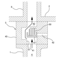
- FIG. 2 is a sectional view showing an embodiment of the detailed configuration of the flow path switching device 5.
- the flow path switching device 5 includes a flow path structure 45 having a pump side flow path 41, a container side flow path 42, and an outflow flow path 43, and a flow path structure 45 disposed within the flow path structure 45.
- a valve body 47 is provided.
- the pump-side flow path 41 communicates with the discharge port 4 of the submersible pump 1
- the container-side flow path 42 communicates with the inside of the suction container 2
- the outflow flow path 43 communicates with the discharge port of the suction container 2 It is connected to 8.
- the valve body 47 is arranged to selectively communicate the outflow passage 43 with either the pump-side passage 41 or the container-side passage 42.
- the configuration of the flow path switching device 5 is not limited to the embodiment shown in FIG. 2 as long as it can perform its intended function.
- FIG. 2 shows the state of the flow path switching device 5 when the submersible pump 1 is not operating.
- the valve body 47 is pressed against the flow path structure 45 by the spring 50 to close the pump side flow path 41 .
- the flow path structure 45 has a valve seat 51 formed around the outlet of the pump side flow path 41, and the valve body 47 is pressed against the valve seat 51 by a spring 50. Therefore, while the valve body 47 is pressed against the valve seat 51, the pump side flow path 41 is closed, and the container side flow path 42 and the outflow flow path 43 are in communication.
- the container-side flow path 42 is open within the suction container 2 and communicates with the suction port 7 through the interior of the suction container 2.
- FIG. 3 shows the state of the flow path switching device 5 when the submersible pump 1 is operating.
- liquefied gas is discharged from the discharge port 4 of the submersible pump 1 and flows into the pump-side channel 41 of the channel switching device 5.
- the liquefied gas flowing through the pump-side channel 41 moves the valve body 47 against the force of the spring 50 to open the pump-side channel 41 and close the container-side channel 42 with the valve body 47 .
- the pump side flow path 41 and the outflow flow path 43 communicate with each other.
- the valve body 47 When the submersible pump 1 stops operating, the valve body 47 is pressed against the valve seat 51 by the spring 50. As a result, as shown in FIG. 2, the pump side flow path 41 is closed, and the container side flow path 42 and the outflow flow path 43 are communicated. In this way, the flow path switching device 5 of this embodiment operates only by the spring 50 and the flow of liquefied gas.
- a dry-up process in which air is removed from the suction container 2 with purge gas and a cool-down process in which the submersible pump 1 is cooled with liquefied gas are performed. Dry-up and cool-down are performed while the submersible pump 1 is not operating. More specifically, dry-up and cool-down are performed with the pump-side flow path 41 closed by the valve body 47 and the container-side flow path 42 and the outflow flow path 43 communicating with each other, as shown in FIG. .
- Drying up is an operation in which purge gas at room temperature is introduced into the suction container 2 to dry the submersible pump 1.
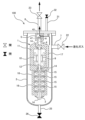
- purge gas is supplied into the suction container 2 through the suction port 7. Drain valve 26 and vent valve 32 are closed, and suction valve 22 and discharge valve 23 are open. Vent valve 32 may be opened.
- the purge gas pushes out the air present in the suction container 2 and is discharged together with the air through the container side flow path 42 and outflow flow path 43 of the flow path switching device 5 and the discharge port 8.
- the interior of the suction container 2 is filled with purge gas, thereby drying the submersible pump 1.
- the pump-side flow path 41 is closed by the valve body 47. Therefore, the purge gas introduced into the suction container 2 does not flow through the submersible pump 1. As a result, unintended rotation of the impeller 15 of the submersible pump 1 is prevented, and damage to sliding parts such as the bearing 14 is prevented.
- the purge gas used for dry-up is an inert gas consisting of an element having a lower boiling point than the elements constituting the liquefied gas. This is to prevent the purge gas from liquefying when it comes into contact with the extremely low temperature liquefied gas introduced after drying.
- the purge gas used is nitrogen gas.
- the purge gas used is helium gas.
- FIGS. 5 and 6 are diagrams illustrating other embodiments of dry-up. The configuration and operation of this embodiment, which are not particularly described, are the same as those of the above embodiment described with reference to FIG. 4, so the redundant explanation will be omitted.
- the pump device 100 includes a vacuum port 61 connected to the suction container 2 and a vacuum valve 63 connected to the vacuum port 61.
- the vacuum port 61 communicates with the inside of the suction container 2 and is connected to a vacuum source (for example, a vacuum pump) not shown.
- drying up includes the steps of creating a vacuum within the suction vessel 2 and introducing a purge gas into the suction vessel 2. The steps of creating a vacuum within the suction vessel 2 and introducing purge gas into the suction vessel 2 may be repeated multiple times until the amount of air within the suction vessel 2 is reduced to an acceptable level.
- FIG. 5 shows an embodiment of the process of creating a vacuum within the suction vessel 2.
- Suction valve 22, discharge valve 23, drain valve 26, and vent valve 32 are closed.
- the vacuum valve 63 When the vacuum valve 63 is opened, a vacuum is created within the suction vessel 2 .
- FIG. 6 shows an embodiment of the process of introducing purge gas into the suction vessel 2.
- FIG. When a vacuum is created in the suction vessel 2, the vacuum valve 63 is closed and the suction valve 22 is opened. Purge gas is supplied into the suction vessel 2 through the suction port 7. Thereafter, when the pressure inside the suction container 2 becomes equal to or higher than atmospheric pressure, the discharge valve 23 is opened.
- the flow path switching device 5 is in the state shown in FIG. 2.
- the purge gas bypasses the submersible pump 1 (that is, the purge gas does not flow inside the submersible pump 1) and passes through the flow path switching device 5.
- the amount of air in the suction container 2 is reduced to an allowable level by repeating the process of evacuating the inside of the suction container 2 shown in FIG. 5 and the step of introducing purge gas into the suction container 2 shown in FIG. 6 multiple times. be able to.
- the vacuum port 61 is connected to the side wall of the suction container 2, but the position of the vacuum port 61 is not limited to this embodiment. In one embodiment, the vacuum port 61 may be connected to the top wall of the suction vessel 2.
- FIG. 7 is a diagram for explaining one embodiment of cool-down of the submersible pump 1.
- liquefied gas is supplied into the suction container 2 through the suction port 7. Drain valve 26 and vent valve 32 are closed, and suction valve 22 and discharge valve 23 are open. Vent valve 32 may be opened.
- the liquefied gas comes into contact with the submersible pump 1 in the suction container 2 and is discharged through the container side flow path 42 and the outflow flow path 43 of the flow path switching device 5, and the discharge port 8.
- the interior of the suction container 2 is filled with liquefied gas, and the submersible pump 1 is thereby cooled.
- the submersible pump 1 During cool-down, the submersible pump 1 is in a stopped state. In FIG. 7, the pump-side flow path 41 is closed by a valve body 47. Therefore, the liquefied gas introduced into the suction container 2 does not flow through the submersible pump 1. That is, the liquefied gas bypasses the submersible pump 1 and passes through the flow path switching device 5. As a result, unintended rotation of the impeller 15 of the submersible pump 1 is prevented, and damage to sliding parts such as the bearing 14 is prevented.
- FIG. 8 is a diagram for explaining another embodiment of cooling down the submersible pump 1.
- liquefied gas is supplied into the suction container 2 through the drain line 25 connected to the bottom of the suction container 2.
- Suction valve 22 and vent valve 32 are closed, and drain valve 26 and discharge valve 23 are open. Vent valve 32 may be opened. While the liquefied gas is introduced from the bottom of the suction container 2, the liquid level of the liquefied gas in the suction container 2 gradually rises.
- the liquefied gas comes into contact with the submersible pump 1 in the suction container 2 and passes through the container-side flow path 42 and outflow path 43 of the flow path switching device 5, and the discharge port 8. be discharged.
- the interior of the suction container 2 is filled with liquefied gas, and the submersible pump 1 is thereby cooled.
- the submersible pump 1 During cool-down, the submersible pump 1 is in a stopped state. In FIG. 8, the pump-side flow path 41 is closed by a valve body 47. Therefore, the liquefied gas introduced into the suction container 2 does not flow through the submersible pump 1. That is, the liquefied gas bypasses the submersible pump 1 and passes through the flow path switching device 5. As a result, unintended rotation of the impeller 15 of the submersible pump 1 is prevented, and damage to sliding parts such as the bearing 14 is prevented.
- hot-up process For maintenance or replacement of the submersible pump 1, before the ultra-low-temperature submersible pump 1 is lifted from the suction container 2, a hot-up process is performed in which the submersible pump 1 is heated with heating gas. Since this hot-up is performed before the submersible pump 1 comes into contact with the surrounding air, components such as nitrogen in the air do not liquefy on the surface of the submersible pump 1. In particular, hot-up is effective when the liquefied gas is liquid hydrogen. That is, when the submersible pump 1 that has been immersed in liquid hydrogen is pulled up from the suction container 2, it is at an extremely low temperature equivalent to that of liquid hydrogen.
- the heated gas is an inert gas at room temperature made of an element having a boiling point lower than the boiling point of the elements constituting the liquefied gas. This is to prevent the heated gas from liquefying when it comes into contact with the submersible pump 1 at a very low temperature.
- the liquefied gas is liquefied natural gas (LNG)
- the warming gas used is nitrogen gas.
- the warming gas used is helium gas.
- the warming gas may be a vaporized liquefied gas (also referred to as boil-off gas (BOG)).
- boil-off gas in a liquefied gas storage tank (not shown) disposed upstream of the submersible pump 1 for storing liquefied gas may be used as the heating gas.
- FIG. 9 is a diagram for explaining an embodiment in which the submersible pump 1 is heated up.
- the heated gas is supplied into the suction container 2 through the suction port 7. Drain valve 26 and vent valve 32 are closed, and suction valve 22 and discharge valve 23 are open. Vent valve 32 may be opened.
- the heated gas bypasses the submersible pump 1 (that is, the heated gas does not flow inside the submersible pump 1) and passes through the flow path switching device 5.
- the heated gas comes into contact with the submersible pump 1 in the suction container 2 and is discharged through the container side flow path 42 and the outflow flow path 43 of the flow path switching device 5, and the discharge port 8.
- the interior of the suction container 2 is filled with heated gas, and the submersible pump 1 is thereby heated.
- FIG. 10 is a diagram for explaining another embodiment of hot-up of the submersible pump 1.
- the heated gas is supplied into the suction container 2 through the drain line 25 connected to the bottom of the suction container 2. .
- Suction valve 22 and vent valve 32 are closed, and drain valve 26 and discharge valve 23 are open. Vent valve 32 may be opened.
- the heated gas contacts the submersible pump 1 in the suction container 2, and flows through the container-side flow path 42, the outflow flow path 43, and the discharge port of the flow path switching device 5. It is discharged through 8.
- the interior of the suction container 2 is filled with heated gas, and the submersible pump 1 is thereby heated.
- the submersible pump 1 During hot-up, the submersible pump 1 is in a stopped state. In FIG. 10, the pump-side flow path 41 is closed by a valve body 47. Therefore, the heated gas introduced into the suction container 2 does not flow through the submersible pump 1. That is, the heated gas bypasses the submersible pump 1 and passes through the flow path switching device 5 . As a result, unintended rotation of the impeller 15 of the submersible pump 1 is prevented, and damage to sliding parts such as the bearing 14 is prevented.
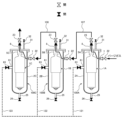
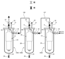
- FIG. 11 is a schematic diagram showing an embodiment of a pump system including a plurality of pump devices 100A, 100B, and 100C connected in series.
- the plurality of pump devices 100A, 100B, and 100C have the same configuration as the pump device 100 described with reference to FIGS. 1 to 10.
- the submersible pump, suction container, and flow path switching device of the pump device 100A are respectively referred to as a submersible pump 1A, suction container 2A, and flow path switching device 5A
- the submersible pump of the pump device 100B is referred to as a submersible pump 1A, a suction container 2A, and a flow path switching device 5A
- the suction container, and the flow path switching device are respectively referred to as a submersible pump 1B, a suction container 2B, and a flow path switching device 5B. They are respectively referred to as a pump 1C, a suction container 2C, and a flow path switching device 5C.
- the pump device 100A is arranged upstream of the pump device 100B, and the pump device 100B is arranged upstream of the pump device 100C.
- the suction port 7 of the pump device 100A is connected to a liquefied gas storage tank 105 in which liquefied gas is stored.
- Pump device 100A is connected in series to pump device 100B by communication line 107, and pump device 100B is connected in series to pump device 100C by communication line 108. More specifically, the discharge port 8 of the pump device 100A is connected to the suction port 7 of the pump device 100B by a communication line 107, and the discharge port 8 of the pump device 100B is connected to the suction port 7 of the pump device 100C. They are connected by a line 108.
- the submersible pumps 1A, 1B, and 1C are connected in series in the order of submersible pump 1A, submersible pump 1B, and submersible pump 1C.
- the liquefied gas is sequentially pressurized by these submersible pumps 1A, 1B, and 1C.
- the flow path switching devices 5A, 5B, and 5C are in the state shown in FIG. 3.
- FIG. 12 is a diagram illustrating an embodiment in which dry-up is performed on the serially connected submersible pumps 1A, 1B, and 1C shown in FIG. 11.
- the purge gas sequentially flows into the suction containers 2A, 2B, and 2C of the pump devices 100A, 100B, and 100C through the respective suction ports 7.
- the submersible pumps 1A, 1B, and 1C are in a stopped state. Therefore, the flow path switching devices 5A, 5B, and 5C are in the state shown in FIG. 2.
- the purge gas bypasses the submersible pumps 1A, 1B, and 1C (that is, the purge gas does not flow inside the submersible pumps 1A, 1B, and 1C), and enters the flow path switching devices 5A, 5B, and 5C. pass through.
- purge gas is first introduced into the suction container 2A of the pump device 100A through the suction port 7.
- the purge gas is passed through the flow path switching device 5A while bypassing the submersible pump 1A.
- the purge gas that has passed through the flow path switching device 5A is introduced into the suction container 2B through the communication line 107 and the suction port 7 of the pump device 100B.
- the purge gas is passed through the flow path switching device 5B while bypassing the submersible pump 1B.
- the purge gas that has passed through the flow path switching device 5B is introduced into the suction container 2C through the communication line 108 and the suction port 7 of the pump device 100C.
- the purge gas is passed through the flow path switching device 5C while bypassing the submersible pump 1C.
- the purge gas is discharged through the discharge port 8 of the pump device 100C.
- the flow path switching devices 5A, 5B, 5C prevent the purge gas introduced into the suction containers 2A, 2B, 2C during dry-up from being introduced into the submersible pumps 1A, 1B, 1C. be able to. Therefore, the impellers of the submersible pumps 1A, 1B, 1C that are not in operation do not rotate, and as a result, damage to sliding parts such as bearings of the submersible pumps 1A, 1B, 1C can be prevented.
- FIGS. 13 and 14 are diagrams illustrating an embodiment in which dry-up is performed for the plurality of pump devices 100A, 100B, and 100C of the embodiment described with reference to FIGS. 5 and 6.
- the configuration and operation of this embodiment, which are not particularly described, are the same as those of the embodiment described with reference to FIG. 12, so the redundant explanation will be omitted.
- Vacuum ports 61 and vacuum valves 63 of pump devices 100A, 100B, and 100C are connected to vacuum lines 121, 122, and 123, respectively.
- FIG. 13 shows an embodiment of the process of forming a vacuum in the suction containers 2A, 2B, 2C of the pump devices 100A, 100B, 100C.
- the suction valve 22, discharge valve 23, drain valve 26, and vent valve 32 of the pump devices 100A, 100B, and 100C are closed, and the vacuum valve 63 is opened. This creates a vacuum within the suction containers 2A, 2B, and 2C.
- FIG. 14 shows an embodiment of the process of introducing purge gas into the suction vessels 2A, 2B, and 2C.
- the vacuum valves 63 of the pump devices 100A, 100B, 100C are closed and the suction valves 22 are opened.
- the purge gas sequentially flows into the suction vessels 2A, 2B, 2C of the pump devices 100A, 100B, 100C through the respective suction ports 7. Thereafter, when the pressure in the suction containers 2A, 2B, 2C becomes equal to or higher than atmospheric pressure, the discharge valves 23 of the pump devices 100A, 100B, 100C are opened.
- the submersible pumps 1A, 1B, and 1C are in a stopped state. Therefore, the flow path switching devices 5A, 5B, and 5C are in the state shown in FIG. 2.
- the purge gas bypasses the submersible pumps 1A, 1B, and 1C (that is, the purge gas does not flow inside the submersible pumps 1A, 1B, and 1C), and passes through the flow path switching devices 5A, 5B, and 5C. do.
- FIG. 15 is a diagram showing an embodiment of cool down for cooling the submersible pumps 1A, 1B, and 1C.
- the liquefied gas sequentially flows into the suction containers 2A, 2B, and 2C of the pump devices 100A, 100B, and 100C through the respective suction ports 7.
- the submersible pumps 1A, 1B, and 1C are in a stopped state. Therefore, the flow path switching devices 5A, 5B, and 5C are in the state shown in FIG. 2.
- the liquefied gas bypasses the submersible pumps 1A, 1B, 1C (that is, the liquefied gas does not flow inside the submersible pumps 1A, 1B, 1C), and the flow path switching devices 5A, 5B, Pass through 5C.
- liquefied gas is first introduced into the suction container 2A of the pump device 100A through the suction port 7.
- the liquefied gas is passed through the flow path switching device 5A while bypassing the submersible pump 1A.
- the liquefied gas that has passed through the flow path switching device 5A is introduced into the suction container 2B through the communication line 107 and the suction port 7 of the pump device 100B.
- the liquefied gas is passed through the flow path switching device 5B while bypassing the submersible pump 1B.
- the liquefied gas that has passed through the flow path switching device 5B is introduced into the suction container 2C through the communication line 108 and the suction port 7 of the pump device 100C.
- the liquefied gas is passed through the flow path switching device 5C while bypassing the submersible pump 1C.
- the liquefied gas is discharged through the discharge port 8 of the pump device 100C.
- the flow path switching devices 5A, 5B, 5C prevent the liquefied gas introduced into the suction containers 2A, 2B, 2C during cool-down from being introduced into the submersible pumps 1A, 1B, 1C. be able to. Therefore, the impellers of the submersible pumps 1A, 1B, 1C that are not in operation do not rotate, and as a result, damage to sliding parts such as bearings of the submersible pumps 1A, 1B, 1C can be prevented.
- FIG. 16 is a diagram showing another embodiment of the cool-down method for cooling the submersible pumps 1A, 1B, and 1C. As shown in FIG. 16, the drain line 25 and drain valve 26 of the pump device 100A are connected to a liquefied gas storage tank 105 in which liquefied gas is stored.
- the drain line 25 and drain valve 26 of the pump device 100B are connected to the discharge port 8 of the pump device 100A through a communication line 131.
- a portion of the communication line 107 connecting the suction port 7 of the pump device 100B and the discharge port 8 of the pump device 100A may constitute a portion of the communication line 131.
- the drain line 25 and drain valve 26 of the pump device 100C are connected to the discharge port 8 of the pump device 100B through a communication line 132.
- a portion of the communication line 108 connecting the suction port 7 of the pump device 100C and the discharge port 8 of the pump device 100B may constitute a portion of the communication line 132.
- the liquefied gas is sequentially supplied into the suction containers 2A, 2B, and 2C through the drain lines 25 connected to the bottoms of the suction containers 2A, 2B, and 2C.
- Suction valve 22 and vent valve 32 are closed, and drain valve 26 and discharge valve 23 are open. While the liquefied gas is introduced from the bottom of the suction containers 2A, 2B, 2C, the liquid level of the liquefied gas in the suction containers 2A, 2B, 2C gradually rises.
- the submersible pumps 1A, 1B, and 1C are in a stopped state. Therefore, the flow path switching devices 5A, 5B, and 5C are in the state shown in FIG. 2. Therefore, the liquefied gas bypasses the submersible pumps 1A, 1B, 1C (that is, the liquefied gas does not flow inside the submersible pumps 1A, 1B, 1C), and the flow path switching devices 5A, 5B, Pass through 5C.
- the liquefied gas is first introduced into the suction container 2A of the pump device 100A through the drain line 25.
- the liquefied gas is passed through the flow path switching device 5A while bypassing the submersible pump 1A.
- the liquefied gas that has passed through the flow path switching device 5A is introduced into the suction container 2B through the communication line 131 and the drain line 25 of the pump device 100B.
- the liquefied gas is passed through the flow path switching device 5B while bypassing the submersible pump 1B.
- the liquefied gas that has passed through the flow path switching device 5B is introduced into the suction container 2C through the communication line 132 and the drain line 25 of the pump device 100C.
- the liquefied gas is passed through the flow path switching device 5C while bypassing the submersible pump 1C.
- the liquefied gas is discharged through the discharge port 8 of the pump device 100C.
- FIG. 17 is a diagram showing an embodiment of hot-up for heating the submersible pumps 1A, 1B, and 1C.
- the heated gas sequentially flows into the suction containers 2A, 2B, and 2C of the pump devices 100A, 100B, and 100C through the respective suction ports 7.
- the submersible pumps 1A, 1B, and 1C are in a stopped state. Therefore, the flow path switching devices 5A, 5B, and 5C are in the state shown in FIG. 2. Therefore, the heated gas bypasses the submersible pumps 1A, 1B, 1C (that is, the heated gas does not flow inside the submersible pumps 1A, 1B, 1C), and the flow path switching device 5A, Pass through 5B and 5C.
- the heated gas is first introduced into the suction container 2A of the pump device 100A through the suction port 7.
- the heated gas is passed through the flow path switching device 5A while bypassing the submersible pump 1A.
- the heated gas that has passed through the flow path switching device 5A is introduced into the suction container 2B through the communication line 107 and the suction port 7 of the pump device 100B.
- the heated gas is passed through the flow path switching device 5B while bypassing the submersible pump 1B.
- the heated gas that has passed through the flow path switching device 5B is introduced into the suction container 2C through the communication line 108 and the suction port 7 of the pump device 100C.
- the heated gas is passed through the flow path switching device 5C while bypassing the submersible pump 1C.
- the heated gas is discharged through the discharge port 8 of the pump device 100C.
- the flow path switching devices 5A, 5B, 5C prevent the heated gas introduced into the suction containers 2A, 2B, 2C during hot-up from being introduced into the submersible pumps 1A, 1B, 1C. can be prevented. Therefore, the impellers of the submersible pumps 1A, 1B, 1C that are not in operation do not rotate, and as a result, damage to sliding parts such as bearings of the submersible pumps 1A, 1B, 1C can be prevented.
- FIG. 18 is a diagram showing another embodiment of hot-up for heating the submersible pumps 1A, 1B, and 1C.
- the drain line 25 and drain valve 26 of the pump device 100B are connected to the discharge port 8 of the pump device 100A through a communication line 131.
- a portion of the communication line 107 connecting the suction port 7 of the pump device 100B and the discharge port 8 of the pump device 100A may constitute a portion of the communication line 131.
- the drain line 25 and drain valve 26 of the pump device 100C are connected to the discharge port 8 of the pump device 100B through a communication line 132.
- a portion of the communication line 108 connecting the suction port 7 of the pump device 100C and the discharge port 8 of the pump device 100B may constitute a portion of the communication line 132.
- heated gas is sequentially supplied into the suction vessels 2A, 2B, 2C through the drain lines 25 connected to the bottoms of the suction vessels 2A, 2B, 2C.
- Suction valve 22 and vent valve 32 are closed, and drain valve 26 and discharge valve 23 are open.
- the heated gas comes into contact with the submersible pumps 1A, 1B, 1C in the suction containers 2A, 2B, 2C while being introduced from the bottoms of the suction containers 2A, 2B, 2C.
- the submersible pumps 1A, 1B, and 1C are in a stopped state. Therefore, the flow path switching devices 5A, 5B, and 5C are in the state shown in FIG. 2. Therefore, the heated gas bypasses the submersible pumps 1A, 1B, 1C (that is, the heated gas does not flow inside the submersible pumps 1A, 1B, 1C), and the flow path switching device 5A, Pass through 5B and 5C.
- the heated gas is first introduced into the suction container 2A of the pump device 100A through the drain line 25.
- the heated gas is passed through the flow path switching device 5A while bypassing the submersible pump 1A.
- the heated gas that has passed through the flow path switching device 5A is introduced into the suction container 2B through the communication line 131 and the drain line 25 of the pump device 100B.
- the heated gas is passed through the flow path switching device 5B while bypassing the submersible pump 1B.
- the heated gas that has passed through the flow path switching device 5B is introduced into the suction container 2C through the communication line 132 and the drain line 25 of the pump device 100C.
- the heated gas is passed through the flow path switching device 5C while bypassing the submersible pump 1C.
- the heated gas is discharged through the discharge port 8 of the pump device 100C.
- the pump system of the embodiment shown in FIGS. 11 to 18 includes three pump devices 100A, 100B, and 100C connected in series, the number of pump devices is not limited to this embodiment. In one embodiment, the pump system may include only two pump devices connected in series, or it may include four or more pump devices connected in series.
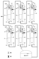
- FIG. 19 is a schematic diagram showing another embodiment of a pump system including a plurality of pump devices connected in series.
- the configuration and operation of this embodiment, which are not particularly described, are the same as those of the embodiment described with reference to FIG. 11, so the redundant explanation will be omitted.
- the pump system of the embodiment shown in FIG. 19 further includes pump devices 100D, 100E, and 100F that are connected in series in addition to pump devices 100A, 100B, and 100C that are connected in series.
- the pump device 100D includes a suction container 2D, a submersible pump 1D disposed in the suction container 2D, and a flow path switching device 5D
- the pump device 100E includes a suction container 2E and a submersible pump 1D disposed in the suction container 2D
- the pump device 100F includes a submersible pump 1E and a flow path switching device 5E, and includes a suction container 2F, a submersible pump 1F and a flow path switching device 5F disposed in the suction container 2F.
- the pump device 100D is connected in series to the pump device 100E by a communication line 109, and the pump device 100E is connected in series to the pump device 100F by a communication line 110. More specifically, the discharge port 23 of the pump device 100D is connected to the suction port 7 of the pump device 100E by a communication line 109, and the discharge port 23 of the pump device 100E is connected to the suction port 7 of the pump device 100F. They are connected by a line 110.
- Pump devices 100D, 100E, and 100F are arranged in parallel with pump devices 100A, 100B, and 100C. Since the plurality of pump devices 100A, 100B, 100C, 100D, 100E, and 100F have the same configuration as the pump device 100 described with reference to FIGS. 1 to 3, their overlapping description will be omitted.
- the pump device 100A and the pump device 100D are connected to a liquefied gas storage tank 105 in which liquefied gas is stored. According to the embodiment shown in FIG. 19, liquefied gas is pumped by submersible pumps 1A to 1C of pump devices 100A to 100C and submersible pumps 1D to 1F of pump devices 100D to 100F arranged in parallel. Ru.
- FIG. 20 is a diagram showing how dry-up is performed on the plurality of pump devices 100A to 100F of the pump system shown in FIG. 19.
- the suction valves 22 and discharge valves 23 of the pump devices 100A to 100F are opened, and the drain valves 26 and vent valves 32 are closed.
- the purge gas flows through the pump devices 100A to 100C and the pump devices 100D to 100F in parallel. More specifically, the purge gas is introduced into the suction vessels 2A, 2B, 2C, 2D, 2E, 2F through the respective suction ports 7. Further, as described with reference to FIG. 4, the purge gas is supplied to the flow path switching devices 5A to 5F while bypassing the submersible pumps 1A to 1F (without flowing inside the submersible pumps 1A to 1F). flows through.
- FIGS. 21 and 22 are diagrams showing an embodiment in which dry-up is performed on the plurality of pump devices 100A to 100F of the embodiment described with reference to FIGS. 5 and 6.
- the arrangement of the pump devices 100A to 100F, which is not particularly described, is the same as that in the embodiment described with reference to FIG. 19, so a redundant description thereof will be omitted.
- Vacuum ports 61 and vacuum valves 63 of pump devices 100A, 100B, and 100C are connected to vacuum lines 121, 122, and 123, respectively, and vacuum ports 61 and vacuum valves 63 of pump devices 100D, 100E, and 100F are connected to vacuum lines 124, 125 and 126, respectively.
- the vacuum lines 121, 122, 123, 124, 125, and 126 are connected to a vacuum source (for example, a vacuum pump) not shown.
- FIG. 21 shows an embodiment of the process of forming a vacuum in the suction containers 2A to 2F of the pump devices 100A to 100F.
- the suction valve 22, discharge valve 23, drain valve 26, and vent valve 32 of the pump devices 100A to 100F are closed, and the vacuum valve 63 is opened. As a result, a vacuum is formed within the suction containers 2A to 2F.
- FIG. 22 shows an embodiment of the process of introducing purge gas into the suction containers 2A to 2F.
- the vacuum valves 63 of the pump devices 100A to 100F are closed and the suction valves 22 are opened.
- the purge gas sequentially flows into the suction vessels 2A to 2F of the pump devices 100A to 100F through the respective suction ports 7. Thereafter, when the pressure inside the suction containers 2A to 2F becomes equal to or higher than atmospheric pressure, the discharge valves 23 of the pump devices 100A to 100F are opened.
- the submersible pumps 1A to 1F are in a stopped state. Therefore, the flow path switching devices 5A to 5F are in the state shown in FIG. 2.
- the purge gas bypasses the submersible pumps 1A to 1F (that is, the purge gas does not flow inside the submersible pumps 1A to 1F) and passes through the flow path switching devices 5A to 5F.
- the step of forming a vacuum in the suction containers 2A to 2F shown in FIG. 21 and the step of introducing purge gas to the suction containers 2A to 2F shown in FIG. may be repeated multiple times until reduced.
- FIG. 23 is a diagram showing an embodiment in which a plurality of pump devices 100A to 100F of the pump system shown in FIG. 19 are cooled down.
- the suction valves 22 and discharge valves 23 of the pump devices 100A to 100F are opened, and the drain valves 26 and vent valves 32 are closed.
- the liquefied gas flows in parallel through the pump devices 100A to 100C and the pump devices 100D to 100F. More specifically, the liquefied gas is introduced into the suction containers 2A, 2B, 2C, 2D, 2E, 2F through the respective suction ports 7. Furthermore, as described with reference to FIG. 7, the liquefied gas is transferred to the flow path switching devices 5A to 1F while bypassing the submersible pumps 1A to 1F (without flowing inside the submersible pumps 1A to 1F). It flows through 5F.
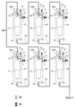
- FIG. 24 is a diagram showing another embodiment in which a plurality of pump devices 100A to 100F of the pump system shown in FIG. 19 are cooled down. As shown in FIG. 24, the drain lines 25 and drain valves 26 of the pump devices 100A and 100D are connected to a liquefied gas storage tank 105 in which liquefied gas is stored.
- the drain line 25 and drain valve 26 of the pump device 100B are connected to the discharge port 8 of the pump device 100A through a communication line 131.
- the drain line 25 and drain valve 26 of the pump device 100C are connected to the discharge port 8 of the pump device 100B through a communication line 132.
- the drain line 25 and drain valve 26 of the pump device 100E are connected to the discharge port 8 of the pump device 100D through a communication line 133.
- the drain line 25 and drain valve 26 of the pump device 100F are connected to the discharge port 8 of the pump device 100E through a communication line 134.
- the suction valves 22 and vent valves 32 of the pump devices 100A to 100F are closed, and the drain valves 26 and discharge valves 23 are opened.
- the liquefied gas flows in parallel through the pump devices 100A to 100C and the pump devices 100D to 100F. More specifically, the liquefied gas is introduced into the suction containers 2A, 2B, 2C, 2D, 2E, 2F through the respective drain lines 25. While the liquefied gas is introduced from the bottoms of the suction containers 2A to 2F, the liquid level of the liquefied gas in the suction containers 2A to 2F gradually rises.
- the flow path switching devices 5A to 5F are in the state shown in FIG. 2. As explained with reference to FIG. 8, the liquefied gas passes through the flow path switching devices 5A to 5F while bypassing the submersible pumps 1A to 1F (without flowing inside the submersible pumps 1A to 1F). flows through.
- FIG. 25 is a diagram showing how the plurality of pump devices 100A to 100F of the pump system shown in FIG. 19 are heated up.
- the suction valves 22 and discharge valves 23 of the pump devices 100A to 100F are opened, and the drain valves 26 and vent valves 32 are closed.
- the heated gas flows through pump devices 100A to 100C and pump devices 100D to 100F in parallel. More specifically, the heated gas is introduced into the suction vessels 2A, 2B, 2C, 2D, 2E, 2F through the respective suction ports 7. Further, as described with reference to FIG. 9, the heated gas is supplied to the flow path switching device 5A while bypassing the submersible pumps 1A to 1F (without flowing inside the submersible pumps 1A to 1F). It flows through ⁇ 5F.
- FIG. 26 is a diagram showing another embodiment in which a plurality of pump devices 100A to 100F of the pump system shown in FIG. 19 are heated up.
- the drain line 25 and drain valve 26 of the pump device 100B are connected to the discharge port 8 of the pump device 100A through a communication line 131.
- the drain line 25 and drain valve 26 of the pump device 100C are connected to the discharge port 8 of the pump device 100B through a communication line 132.
- the drain line 25 and drain valve 26 of the pump device 100E are connected to the discharge port 8 of the pump device 100D through a communication line 133.
- the drain line 25 and drain valve 26 of the pump device 100F are connected to the discharge port 8 of the pump device 100E through a communication line 134.
- the suction valves 22 and vent valves 32 of the pump devices 100A to 100F are closed, and the drain valves 26 and discharge valves 23 are opened.
- the heated gas flows through pump devices 100A to 100C and pump devices 100D to 100F in parallel. More specifically, the heated gas is introduced into the suction vessels 2A, 2B, 2C, 2D, 2E, 2F through respective drain lines 25. The heated gas comes into contact with the submersible pumps 1A to 1F inside the suction containers 2A to 2F while being introduced from the bottoms of the suction containers 2A to 2F.
- the flow path switching devices 5A to 5F are in the state shown in FIG. 2. As explained with reference to FIG. 10, the heated gas is passed through the flow path switching devices 5A to 5F while bypassing the submersible pumps 1A to 1F (without flowing inside the submersible pumps 1A to 1F). flows through.
- FIG. 27 is a schematic diagram showing still another embodiment of a pump system including a plurality of pump devices connected in series.
- the configuration and operation of this embodiment, which are not particularly described, are the same as those of the embodiment described with reference to FIG. 19, so the redundant explanation will be omitted.
- a communication line 107 that connects the pump device 100A and the pump device 100B is connected by an intermediate header 111 to a communication line 109 that connects the pump device 100D and the pump device 100E.
- a communication line 108 connecting the pump device 100B and the pump device 100C is connected by an intermediate header 112 to a communication line 110 connecting the pump device 100E and the pump device 100F.
- the pump devices 100A to 100C are also connected in series to the pump devices 100D to 100F by intermediate headers 111 and 112. As a result, various flows of liquefied gas are formed, allowing various operations of the pump devices 100A to 100C and pump devices 100D to 100F. For example, it is also possible to stop the operation of the pump device 100C or the pump device 100F for maintenance or depending on the pressure required on the demand side.
- the dry-up, cool-down, and hot-up of the pump system shown in FIG. 27 is performed in a manner similar to the embodiment described with reference to FIGS. 20-26.
- Purge gas, liquefied gas, and warm gas may flow through intermediate headers 111, 112 in various manners.
- pump devices 100A to 100C and pump devices 100D to 100F are provided in parallel, but three or more rows of pump devices may be provided in parallel. .
- FIG. 28 is a sectional view showing another embodiment of the flow path switching device 5.
- the channel structure 45 includes a bypass channel 55 that communicates the pump side channel 41 and the outflow channel 43.
- the cross-sectional area of the bypass flow path 55 is smaller than the cross-sectional area of the pump-side flow path 41. More specifically, the cross-sectional area of the bypass flow path 55 is such that the valve body 47 closes the pump side flow path 41 and the fluid (purge gas, liquefied gas, or heated gas) flows through the submersible pump 1 and the bypass flow path. 55, the impeller 15 of the submersible pump 1 has a cross-sectional area that does not rotate due to the flow of the fluid.
- the bypass passage 55 may be a through hole as shown in FIG. 28, or a groove formed in the valve seat 51.
- a plurality of bypass channels 55 may be provided as long as the fluid does not rotate the impeller 15.
- fluid such as purge gas, liquefied gas, or heated gas can be smoothly introduced into the submersible pump 1 during dry-up, cool-down, and hot-up. As a result, dry-up, cool-down, and hot-up of the submersible pump 1 can be completed in a shorter time.
- bypass channel 55 eliminates the liquid level difference between the inside and outside of the submersible pump 1 when liquefied gas is introduced into the suction container 2 during cool-down, and The stress generated within the submersible pump 1 due to the temperature difference between the inside and outside can be reduced.
- the flow path switching device 5 described with reference to FIG. 28 may be applied to the flow path switching devices 5, 5A to 5F in the embodiments described with reference to FIGS. 4 to 27.
- FIG. 29 is a sectional view showing still another embodiment of the flow path switching device 5.
- the valve body 47 includes a through hole 57 that allows the pump-side flow path 41 and the outflow flow path 43 to communicate with each other.
- the through hole 57 extends from the pump side of the valve body 47 to the opposite side of the pump.
- the cross-sectional area of the through hole 57 is smaller than the cross-sectional area of the pump side flow path 41.
- the cross-sectional area of the through hole 57 is such that the valve body 47 closes the pump side flow path 41 and the fluid (purge gas, liquefied gas, or heated gas) passes through the submersible pump 1 and the through hole 57.
- This is the cross-sectional area where the impeller 15 of the submersible pump 1 does not rotate due to the flow of the fluid when the fluid flows.
- a plurality of through holes 57 may be provided in the valve body 47.
- fluid such as purge gas, liquefied gas, or heated gas can be smoothly introduced into the submersible pump 1 during dry-up, cool-down, and hot-up.
- dry-up, cool-down, and hot-up of the submersible pump 1 can be completed in a shorter time.
- the through hole 57 eliminates the liquid level difference between the inside and outside of the submersible pump 1. It is possible to reduce the stress generated within the submersible pump 1 due to the temperature difference between the submersible pump 1 and the outside.
- the flow path switching device 5 described with reference to FIG. 29 may be applied to the flow path switching devices 5, 5A to 5F in the embodiments described with reference to FIGS. 4 to 27.
- FIG. 30 is a sectional view showing another embodiment of the submersible pump 1.
- the motor housing 13 of the electric motor 11 has a through hole 70.
- Motor rotor 9 and motor stator 10 are arranged within motor housing 13 .
- the through hole 70 is formed in the upper part of the submersible pump 1 (in this embodiment, the upper wall of the motor housing 13), and is located above the impeller 15, the motor rotor 9, and the motor stator 10.
- the through hole 70 communicates the inside and outside of the submersible pump 1.
- the cross-sectional area of the through hole 70 is smaller than the cross-sectional area of the pump side flow path 41 of the flow path switching device 5. More specifically, the cross-sectional area of the through hole 70 is such that the valve body 47 closes the pump side flow path 41 and the fluid (purge gas, liquefied gas, or heated gas) flows through the submersible pump 1 and the through hole 70. This is the cross-sectional area where the impeller 15 of the submersible pump 1 does not rotate due to the flow of the fluid when the fluid flows.
- a fluid such as purge gas, liquefied gas, or heated gas
- a fluid such as purge gas, liquefied gas, or heated gas
- a portion of the fluid passes through the suction port 3 to the submersible pump. 1.
- a portion of the fluid further flows into the motor housing 13 of the electric motor 11.
- the gas present in the submersible pump 1 is removed from the submersible pump 1 through the through hole 70 by the inflowing fluid.
- fluid such as purge gas, liquefied gas, or heated gas
- fluid such as purge gas, liquefied gas, or heated gas
- the through hole 70 eliminates the liquid level difference between the inside and outside of the submersible pump 1, and It is possible to reduce the stress generated within the submersible pump 1 due to the temperature difference between the submersible pump 1 and the outside.
- a plurality of through holes 70 may be provided in the motor housing 13 as long as the fluid does not cause the impeller 15 to rotate.
- the submersible pump 1 may further include a gas vent valve 75 connected to the through hole 70.
- the gas vent valve 75 is fixed to the motor housing 13.
- the gas vent valve 75 is configured to close when the submersible pump 1 is in operation, and open when the submersible pump 1 is stopped.
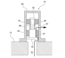
- FIG. 32 is a sectional view showing one embodiment of the gas vent valve 75.
- the gas vent valve 75 includes a seal valve body 78, a valve rod 79 connected to the seal valve body 78, and a valve pedestal 82 having a flow path 81 that allows passage of a fluid such as purge gas, liquefied gas, or heated gas.
- a rod support structure 85 that supports the valve rod 79 so as to be movable in its axial direction; a spring 88 as a biasing member that biases the seal valve body 78 and the valve rod 79 in a direction away from the valve seat 82;
- a valve housing 90 is provided that accommodates a seal valve body 78, a valve rod 79, and a valve seat 82 therein.
- the valve housing 90 has a relief hole 91 that communicates with the flow path 81 of the valve pedestal 82.
- the relief hole 91 communicates the inside and outside of the valve housing 90.
- the inside of the valve housing 90 communicates with the through hole 70 of the motor housing 13, and the valve housing 90 covers the outlet of the through hole 70.
- Spring 88 is disposed between rod support structure 85 and seal valve body 78 . More specifically, one end of spring 88 contacts rod support structure 85 and the other end of spring 88 contacts valve rod 79. The spring 88 pushes down the valve rod 79 and the seal valve body 78 together, separating the seal valve body 78 from the flow path 81 of the valve seat 82. Therefore, as shown in FIG. 32, the flow path 81 communicates with the through hole 70 of the motor housing 13.
- the movement of the valve rod 79 and the seal valve body 78 in the axial direction by the spring 88 is restricted by a rod movement limiting member 93 fixed to the valve rod 79.
- the position and structure of the rod movement limiting member 93 are not limited to the embodiment shown in FIG. 32.
- the rod movement limiting member 93 may be provided on the valve housing 90 or the motor housing 13.
- the gas vent valve 75 shown in FIG. 32 is in a state when the operation of the submersible pump 1 is stopped. That is, when the operation of the submersible pump 1 is stopped, the gas vent valve 75 is in an open state.
- the inside of the motor housing 13 communicates with the inside of the suction container 2 (see FIG. 31) through the through hole 70 and the gas vent valve 75 (that is, the flow path 81 and the relief hole 91 of the gas vent valve 75).
- FIG. 33 is a diagram showing the state of the gas vent valve 75 when the submersible pump 1 is in operation.
- a portion of the liquefied gas pressurized by the rotation of the impeller 15 flows into the motor housing 13 through the bearing 14.
- the inside of the motor housing 13 is filled with pressurized liquefied gas.
- the liquefied gas flows into the valve housing 90 through the through hole 70 and pushes up the valve rod 79 and the seal valve body 78 against the force of the spring 88 .
- the seal valve body 78 is pressed against the valve seat 82 by the pressure of the liquefied gas, and closes the flow path 81 of the valve seat 82.
- communication between the flow path 81 of the valve seat 82 and the through hole 70 of the motor housing 13 is cut off. In other words, the vent valve 75 is closed.
- the gas vent valve 75 is closed by the pressure of the liquefied gas, and the liquefied gas inside the motor housing 13 is not discharged to the outside of the motor housing 13. Therefore, the discharge pressure of the submersible pump 1 is prevented from decreasing.
- the gas vent valve 75 When the operation of the submersible pump 1 is stopped, the gas vent valve 75 is open, as shown in FIG. 32.
- fluids such as purge gas, liquefied gas, or warmed gas flow into motor housing 13 and into vent holes 70 and vent valves 75 (i.e., vent valves 75). It is discharged from the motor housing 13 through the flow path 81 of the valve 75 and the relief hole 91). As a result, the fluid can be smoothly introduced into the submersible pump 1.
- FIGS. 30 to 32 may be applied to the embodiment described with reference to FIGS. 4 to 29 as appropriate.
- the present invention provides a dry-up method, a cool-down method, and Available in hot-up method.
Landscapes
- Engineering & Computer Science (AREA)
- Mechanical Engineering (AREA)
- General Engineering & Computer Science (AREA)
- Physics & Mathematics (AREA)
- Thermal Sciences (AREA)
- Life Sciences & Earth Sciences (AREA)
- Sustainable Development (AREA)
- Structures Of Non-Positive Displacement Pumps (AREA)
- Filling Or Discharging Of Gas Storage Vessels (AREA)
- Drying Of Solid Materials (AREA)
Priority Applications (7)
| Application Number | Priority Date | Filing Date | Title |
|---|---|---|---|
| CA3254724A CA3254724A1 (en) | 2022-05-26 | 2023-05-25 | DRYING, COOLING AND HEATING METHOD FOR PUMP DEVICE |
| KR1020247042306A KR20250011678A (ko) | 2022-05-26 | 2023-05-25 | 펌프 장치의 드라이 업 방법, 쿨다운 방법, 및 핫 업 방법 |
| EP23811867.3A EP4534848A1 (en) | 2022-05-26 | 2023-05-25 | Dry-up method, cool-down method, and heat-up method for pump device |
| CN202380040648.9A CN119213222A (zh) | 2022-05-26 | 2023-05-25 | 泵装置的干燥方法、降温方法以及升温方法 |
| JP2024523336A JPWO2023228995A1 (https=) | 2022-05-26 | 2023-05-25 | |
| US18/867,871 US20250361877A1 (en) | 2022-05-26 | 2023-05-25 | Drying-up method, cooling-down method, and hot-up method for a pump apparatus |
| AU2023277957A AU2023277957A1 (en) | 2022-05-26 | 2023-05-25 | Drying method, cooling-down method, and hot-up method for a pump apparatus |
Applications Claiming Priority (2)
| Application Number | Priority Date | Filing Date | Title |
|---|---|---|---|
| JP2022086314 | 2022-05-26 | ||
| JP2022-086314 | 2022-05-26 |
Publications (1)
| Publication Number | Publication Date |
|---|---|
| WO2023228995A1 true WO2023228995A1 (ja) | 2023-11-30 |
Family
ID=88919411
Family Applications (1)
| Application Number | Title | Priority Date | Filing Date |
|---|---|---|---|
| PCT/JP2023/019444 Ceased WO2023228995A1 (ja) | 2022-05-26 | 2023-05-25 | ポンプ装置のドライアップ方法、クールダウン方法、およびホットアップ方法 |
Country Status (8)
| Country | Link |
|---|---|
| US (1) | US20250361877A1 (https=) |
| EP (1) | EP4534848A1 (https=) |
| JP (1) | JPWO2023228995A1 (https=) |
| KR (1) | KR20250011678A (https=) |
| CN (1) | CN119213222A (https=) |
| AU (1) | AU2023277957A1 (https=) |
| CA (1) | CA3254724A1 (https=) |
| WO (1) | WO2023228995A1 (https=) |
Citations (6)
| Publication number | Priority date | Publication date | Assignee | Title |
|---|---|---|---|---|
| JPS59159795U (ja) | 1983-04-12 | 1984-10-26 | 株式会社荏原製作所 | サブマ−ジドモ−タポンプ |
| JPS6231680U (https=) | 1985-08-09 | 1987-02-25 | ||
| JPH05133385A (ja) * | 1991-11-11 | 1993-05-28 | Hitachi Ltd | ドライ真空ポンプ |
| JPH06307376A (ja) * | 1993-04-22 | 1994-11-01 | Hitachi Ltd | 液化ガスタンク用潜没ポンプ装置 |
| JP2007024166A (ja) * | 2005-07-15 | 2007-02-01 | Taiyo Nippon Sanso Corp | 低温液化ガス供給装置 |
| WO2022113450A1 (ja) * | 2020-11-27 | 2022-06-02 | 株式会社荏原製作所 | 流路切り替え装置および潜没式ポンプの空転を防止するための方法 |
Family Cites Families (1)
| Publication number | Priority date | Publication date | Assignee | Title |
|---|---|---|---|---|
| JPS59159795A (ja) | 1983-03-04 | 1984-09-10 | Yakult Honsha Co Ltd | 微生物変換による抱合型ウルソデオキシコ−ル酸の製造方法 |
-
2023
- 2023-05-25 CN CN202380040648.9A patent/CN119213222A/zh active Pending
- 2023-05-25 EP EP23811867.3A patent/EP4534848A1/en active Pending
- 2023-05-25 AU AU2023277957A patent/AU2023277957A1/en active Pending
- 2023-05-25 KR KR1020247042306A patent/KR20250011678A/ko active Pending
- 2023-05-25 US US18/867,871 patent/US20250361877A1/en active Pending
- 2023-05-25 CA CA3254724A patent/CA3254724A1/en active Pending
- 2023-05-25 JP JP2024523336A patent/JPWO2023228995A1/ja active Pending
- 2023-05-25 WO PCT/JP2023/019444 patent/WO2023228995A1/ja not_active Ceased
Patent Citations (6)
| Publication number | Priority date | Publication date | Assignee | Title |
|---|---|---|---|---|
| JPS59159795U (ja) | 1983-04-12 | 1984-10-26 | 株式会社荏原製作所 | サブマ−ジドモ−タポンプ |
| JPS6231680U (https=) | 1985-08-09 | 1987-02-25 | ||
| JPH05133385A (ja) * | 1991-11-11 | 1993-05-28 | Hitachi Ltd | ドライ真空ポンプ |
| JPH06307376A (ja) * | 1993-04-22 | 1994-11-01 | Hitachi Ltd | 液化ガスタンク用潜没ポンプ装置 |
| JP2007024166A (ja) * | 2005-07-15 | 2007-02-01 | Taiyo Nippon Sanso Corp | 低温液化ガス供給装置 |
| WO2022113450A1 (ja) * | 2020-11-27 | 2022-06-02 | 株式会社荏原製作所 | 流路切り替え装置および潜没式ポンプの空転を防止するための方法 |
Also Published As
| Publication number | Publication date |
|---|---|
| EP4534848A1 (en) | 2025-04-09 |
| CN119213222A (zh) | 2024-12-27 |
| CA3254724A1 (en) | 2025-07-03 |
| KR20250011678A (ko) | 2025-01-21 |
| US20250361877A1 (en) | 2025-11-27 |
| AU2023277957A1 (en) | 2025-01-09 |
| JPWO2023228995A1 (https=) | 2023-11-30 |
Similar Documents
| Publication | Publication Date | Title |
|---|---|---|
| JP7780452B2 (ja) | 流路切り替え装置および潜没式ポンプの空転を防止するための方法 | |
| KR102944209B1 (ko) | 극저온 유체를 전달하기 위한 장치 및 방법 | |
| JP2026042986A (ja) | ポンプシステム | |
| WO2023228995A1 (ja) | ポンプ装置のドライアップ方法、クールダウン方法、およびホットアップ方法 | |
| WO2025070458A1 (ja) | ポンプ装置のクールダウン方法 | |
| KR101444315B1 (ko) | 재기화 설비를 이용한 에너지 회수장치 및 그의 운용방법 | |
| AU2024348633A1 (en) | Cooling-down method for pump apparatus | |
| AU2022329695A1 (en) | Purge apparatus and purge method | |
| WO2025211043A1 (ja) | ポンプ装置 | |
| KR102426720B1 (ko) | 공압모터를 이용한 초저온 액체 펌프 및 이를 이용한 초저온 액체 이송방법 | |
| CN119321530B (zh) | 一种置换二氧化碳液货舱中氮气的工艺与系统 | |
| US20250305636A1 (en) | Gas supply system for high and low pressure gas consumer appliances | |
| JP2024176054A (ja) | ポンプシステム、ポンプ搬入方法、ポンプ引き上げ方法 | |
| KR20240132090A (ko) | 액화가스 저장탱크의 쿨링 다운 방법 | |
| CN115751175A (zh) | 一种低温推进剂分段抽空装置 | |
| KR20260053041A (ko) | 잠수식 극저온 액체 수소 펌프 조립체 | |
| JPS6133998B2 (https=) |
Legal Events
| Date | Code | Title | Description |
|---|---|---|---|
| 121 | Ep: the epo has been informed by wipo that ep was designated in this application |
Ref document number: 23811867 Country of ref document: EP Kind code of ref document: A1 |
|
| WWE | Wipo information: entry into national phase |
Ref document number: 202380040648.9 Country of ref document: CN |
|
| WWE | Wipo information: entry into national phase |
Ref document number: 2024523336 Country of ref document: JP |
|
| WWE | Wipo information: entry into national phase |
Ref document number: 18867871 Country of ref document: US |
|
| WWE | Wipo information: entry into national phase |
Ref document number: AU2023277957 Country of ref document: AU |
|
| ENP | Entry into the national phase |
Ref document number: 20247042306 Country of ref document: KR Kind code of ref document: A |
|
| WWE | Wipo information: entry into national phase |
Ref document number: 1020247042306 Country of ref document: KR |
|
| WWP | Wipo information: published in national office |
Ref document number: 202380040648.9 Country of ref document: CN |
|
| NENP | Non-entry into the national phase |
Ref country code: DE |
|
| WWE | Wipo information: entry into national phase |
Ref document number: 2023811867 Country of ref document: EP |
|
| ENP | Entry into the national phase |
Ref document number: 2023811867 Country of ref document: EP Effective date: 20250102 |
|
| ENP | Entry into the national phase |
Ref document number: 2023277957 Country of ref document: AU Date of ref document: 20230525 Kind code of ref document: A |
|
| WWP | Wipo information: published in national office |
Ref document number: 2023811867 Country of ref document: EP |
|
| WWP | Wipo information: published in national office |
Ref document number: 18867871 Country of ref document: US |