WO2023228441A1 - Hydrogen combustion burner - Google Patents
Hydrogen combustion burner Download PDFInfo
- Publication number
- WO2023228441A1 WO2023228441A1 PCT/JP2022/042076 JP2022042076W WO2023228441A1 WO 2023228441 A1 WO2023228441 A1 WO 2023228441A1 JP 2022042076 W JP2022042076 W JP 2022042076W WO 2023228441 A1 WO2023228441 A1 WO 2023228441A1
- Authority
- WO
- WIPO (PCT)
- Prior art keywords
- hydrogen
- combustion
- air
- sintered sheet
- burner
- Prior art date
Links
- 238000002485 combustion reaction Methods 0.000 title claims abstract description 62
- UFHFLCQGNIYNRP-UHFFFAOYSA-N Hydrogen Chemical compound [H][H] UFHFLCQGNIYNRP-UHFFFAOYSA-N 0.000 title claims abstract description 33
- 239000001257 hydrogen Substances 0.000 title claims abstract description 25
- 229910052739 hydrogen Inorganic materials 0.000 title claims abstract description 25
- 239000000835 fiber Substances 0.000 claims abstract description 22
- 239000002184 metal Substances 0.000 claims abstract description 22
- 229910052751 metal Inorganic materials 0.000 claims abstract description 22
- 238000005245 sintering Methods 0.000 claims abstract description 9
- 239000002737 fuel gas Substances 0.000 claims abstract description 5
- 238000009941 weaving Methods 0.000 claims abstract description 5
- 238000009940 knitting Methods 0.000 claims abstract description 4
- 239000000203 mixture Substances 0.000 claims description 49
- 239000000446 fuel Substances 0.000 claims description 32
- 239000008246 gaseous mixture Substances 0.000 abstract 4
- 230000001629 suppression Effects 0.000 description 15
- 230000002093 peripheral effect Effects 0.000 description 7
- 238000009826 distribution Methods 0.000 description 6
- 239000000463 material Substances 0.000 description 6
- 238000001513 hot isostatic pressing Methods 0.000 description 2
- 238000007731 hot pressing Methods 0.000 description 2
- 150000002431 hydrogen Chemical class 0.000 description 2
- 238000000034 method Methods 0.000 description 2
- 239000011148 porous material Substances 0.000 description 2
- 230000000644 propagated effect Effects 0.000 description 2
- 238000011144 upstream manufacturing Methods 0.000 description 2
- 206010061218 Inflammation Diseases 0.000 description 1
- 238000009954 braiding Methods 0.000 description 1
- 239000003638 chemical reducing agent Substances 0.000 description 1
- 239000000567 combustion gas Substances 0.000 description 1
- 239000000470 constituent Substances 0.000 description 1
- 239000002781 deodorant agent Substances 0.000 description 1
- 239000004744 fabric Substances 0.000 description 1
- 230000004054 inflammatory process Effects 0.000 description 1
- 238000003475 lamination Methods 0.000 description 1
- 238000004519 manufacturing process Methods 0.000 description 1
- 238000012986 modification Methods 0.000 description 1
- 230000004048 modification Effects 0.000 description 1
- 229910001220 stainless steel Inorganic materials 0.000 description 1
- 239000010935 stainless steel Substances 0.000 description 1
- XLYOFNOQVPJJNP-UHFFFAOYSA-N water Substances O XLYOFNOQVPJJNP-UHFFFAOYSA-N 0.000 description 1
Images


Classifications
-
- F—MECHANICAL ENGINEERING; LIGHTING; HEATING; WEAPONS; BLASTING
- F23—COMBUSTION APPARATUS; COMBUSTION PROCESSES
- F23D—BURNERS
- F23D14/00—Burners for combustion of a gas, e.g. of a gas stored under pressure as a liquid
- F23D14/12—Radiant burners
- F23D14/16—Radiant burners using permeable blocks
-
- F—MECHANICAL ENGINEERING; LIGHTING; HEATING; WEAPONS; BLASTING
- F23—COMBUSTION APPARATUS; COMBUSTION PROCESSES
- F23D—BURNERS
- F23D14/00—Burners for combustion of a gas, e.g. of a gas stored under pressure as a liquid
- F23D14/46—Details, e.g. noise reduction means
- F23D14/72—Safety devices, e.g. operative in case of failure of gas supply
- F23D14/82—Preventing flashback or blowback
Definitions
- the present invention provides a burner body that uses hydrogen gas as fuel gas and has a mixture chamber to which a mixture of the hydrogen gas and primary air is supplied;
- a hydrogen combustion burner comprising a combustion plate part that covers an open surface of a burner body, and in which the air-fuel mixture is ejected from the combustion plate part and combusted, wherein the combustion plate part weaves or knits metal fibers. It is characterized by having a sintered body sheet obtained by sintering a laminated body without lamination.
- a temperature sensor 4 is disposed in a portion of the mixture chamber 11 located between the combustion plate section 2 and the flashback suppression plate section 3.
- the temperature sensor 4 a known sensor such as a thermocouple or a bimetal switch can be used.
- the temperature sensor 4 detects the temperature rise associated with this.
Abstract
The present invention comprises: a burner body (1) that has a gaseous mixture chamber (11), in which hydrogen gas serves as a fuel gas and which is supplied with a gaseous mixture of the hydrogen gas and primary air; and a combustion plate part (2) that covers an open surface (12) of the burner body facing the gaseous mixture chamber, the present invention being configured such that backfiring can be effectively inhibited in a hydrogen combustion burner where the gaseous mixture is ejected from the combustion plate part and combusted. Used as the combustion plate part is a part having a sintered body sheet obtained by sintering a layered laminate without weaving or knitting metal fibers.
Description
本発明は、水素ガスと空気との混合気を燃焼ガスとして用いる水素燃焼バーナに関する。
The present invention relates to a hydrogen combustion burner that uses a mixture of hydrogen gas and air as combustion gas.
上記種の水素(表面)燃焼バーナは、例えば特許文献1で知られている。このものは、水素ガスと一次空気との混合気が供給される混合気室を有するバーナボディと、混合気室に面するバーナボディの開放面を覆う燃焼板部とを備える。そして、混合気が燃焼板部から噴出して燃焼する。燃焼板部としては、耐高温性材料である金属繊維を織成或いは編組して布帛状に形成したシート材が用いられる。
A hydrogen (surface) combustion burner of the above type is known, for example, from US Pat. This device includes a burner body having a mixture chamber to which a mixture of hydrogen gas and primary air is supplied, and a combustion plate portion covering an open surface of the burner body facing the mixture chamber. Then, the air-fuel mixture is ejected from the combustion plate section and combusted. As the combustion plate portion, a sheet material formed into a fabric by weaving or braiding metal fibers, which are high temperature resistant materials, is used.
然しながら、上記従来例のようなシート材では、繊維同士の接触箇所が多く、それらの接触箇所の面積も大きい。このため、燃焼速度が非常に速い水素ガスと一次空気との混合気を燃焼させることで、燃焼板部の表面近くで混合気が燃焼して燃焼板部の表面側が高温になったときに、その熱が混合気室に面するシート材の裏面側へと伝わり易くなる。このようにシート材の裏面側まで高温になると、火炎が混合気室内に伝播する逆火を生じ易くなるという問題がある。
However, in the sheet material of the conventional example described above, there are many contact points between the fibers, and the areas of these contact points are also large. Therefore, by burning a mixture of hydrogen gas and primary air, which has a very fast combustion rate, when the mixture burns near the surface of the combustion plate and the surface side of the combustion plate becomes high temperature, The heat is easily transmitted to the back side of the sheet material facing the air-fuel mixture chamber. When the temperature reaches the back side of the sheet material in this way, there is a problem in that backfire in which the flame propagates into the air-fuel mixture chamber is likely to occur.
本発明は、以上の点に鑑み、逆火を効果的に抑制することができる水素燃焼バーナを提供することをその課題としている。
In view of the above points, it is an object of the present invention to provide a hydrogen combustion burner that can effectively suppress backfire.
上記課題を解決するために、本発明は、燃料ガスを水素ガスとし、当該水素ガスと一次空気との混合気が供給される混合気室を有するバーナボディと、前記混合気室に面する前記バーナボディの開放面を覆う燃焼板部とを備え、前記混合気が前記燃焼板部から噴出して燃焼する水素燃焼バーナにおいて、前記燃焼板部が、金属繊維を織成したり、編成したりすることなく積層した積層体を焼結した焼結体シートを有することを特徴とする。
In order to solve the above problems, the present invention provides a burner body that uses hydrogen gas as fuel gas and has a mixture chamber to which a mixture of the hydrogen gas and primary air is supplied; A hydrogen combustion burner comprising a combustion plate part that covers an open surface of a burner body, and in which the air-fuel mixture is ejected from the combustion plate part and combusted, wherein the combustion plate part weaves or knits metal fibers. It is characterized by having a sintered body sheet obtained by sintering a laminated body without lamination.
本発明によれば、焼結体シートは、その焼結時に金属繊維がランダムに絡み合って結合(溶着)することで複雑で且つ所謂逆火限界の孔径より小さい無数の微小隙間が形成されたものとなり、しかも、上記従来例のものと比較して金属繊維同士の接触箇所が少なく、また、接触箇所の面積も小さくなる。このため、燃焼板部の表面近くで混合気が燃焼して燃焼板部の表面(燃焼面)側が高温になったとしても、その熱が混合気室に面する焼結体シートの裏面側へと伝わり難くすることができる。しかも、無数の微小隙間を通って常温の混合気が噴出される際に、当該混合気との接触面積が大きくなることで、焼結体シート自体の温度上昇も抑制される。このように本発明では、燃焼板部の焼結体シートには微小隙間しかないことと、焼結体シートの裏面側が高温になり難いこととが相俟って、逆火を効果的に抑制することができる。なお、本発明における金属繊維は、構成材料として半金属を含んでいる。
According to the present invention, the sintered sheet is a sheet in which metal fibers are randomly entangled and bonded (welded) during sintering, thereby forming numerous microscopic gaps that are complex and smaller than the so-called flashback limit pore diameter. Moreover, compared to the conventional example described above, there are fewer contact points between the metal fibers, and the area of the contact points is also smaller. Therefore, even if the air-fuel mixture burns near the surface of the combustion plate and the surface (combustion surface) side of the combustion plate becomes high temperature, the heat is transferred to the back side of the sintered sheet facing the mixture chamber. This can make it difficult to convey. In addition, when the air-fuel mixture at room temperature is ejected through countless minute gaps, the contact area with the air-fuel mixture becomes large, thereby suppressing the temperature rise of the sintered sheet itself. In this way, in the present invention, the fact that there is only a minute gap in the sintered sheet of the combustion plate part and the fact that the back side of the sintered sheet does not easily reach high temperatures combine to effectively suppress backfire. can do. Note that the metal fiber in the present invention contains a semimetal as a constituent material.
本発明において、前記金属繊維がFeと、Al、Cr、Mn及びSiから選択される少なくとも1種またはこれらの炭化物とで構成され、前記焼結体シートの焼結時の目付量が1200g/m2~1800g/m2の範囲に設定されることが好ましい。この場合、目付量が1200g/m2より少ないと、各微小隙間が大きくなり過ぎて逆火を抑制できない虞がある一方で、1800g/m2より多くなると、混合気の通過抵抗が大きくなる。
In the present invention, the metal fiber is composed of Fe and at least one selected from Al, Cr, Mn, and Si or a carbide thereof, and the sintered sheet has a basis weight of 1200 g/m when sintered. It is preferable to set it in the range of 2 to 1800 g/m 2 . In this case, if the basis weight is less than 1200 g/m 2 , each minute gap may become too large and flashback may not be suppressed, while if it exceeds 1800 g/m 2 , the resistance to passage of the air-fuel mixture increases.
また、本発明において、前記金属繊維として、その線径が50μm~100μmの範囲のものを用いることが好ましい。線径が50μmより小さいと、焼結時に金属繊維同士が絡み合う(接触する)面積が増加して焼結体シートの裏面側へ熱が伝わり易くなる一方で、その線径が100μmより大きくなると、各微小隙間が大きくなり過ぎて逆火を抑制できない虞がある。
Further, in the present invention, it is preferable to use metal fibers having a wire diameter in the range of 50 μm to 100 μm. If the wire diameter is smaller than 50 μm, the area where the metal fibers intertwine (contact) with each other increases during sintering, making it easier for heat to be transferred to the back side of the sintered sheet, whereas if the wire diameter is larger than 100 μm, There is a possibility that each minute gap becomes too large and it is not possible to suppress backfire.
更に、本発明において、前記焼結体シートが60%~80%の範囲の空隙率を持つことが好ましい。これにより、混合気が焼結体シートを通過するときの圧力損失を抑制することができる。
Further, in the present invention, it is preferable that the sintered sheet has a porosity in the range of 60% to 80%. Thereby, pressure loss when the air-fuel mixture passes through the sintered body sheet can be suppressed.
また、本発明において、前記焼結体シートが前記混合気の流れ方向下流側に向けて凸の湾曲形状に成形されることが好ましい。これにより、焼結体シートの表面側が加熱されたときに、焼結体シート自体が歪み難くでき、焼結体シートが局所的に高温になって逆火することを抑制することができる。
Further, in the present invention, it is preferable that the sintered sheet is formed into a curved shape convex toward the downstream side in the flow direction of the air-fuel mixture. Thereby, when the front side of the sintered sheet is heated, the sintered sheet itself can be made less likely to be distorted, and it is possible to prevent the sintered sheet from locally becoming high temperature and causing backfire.
以下、図面を参照して、燃料ガスとして水素ガスを用いる本発明の水素燃焼バーナCBの実施形態を説明する。なお、本発明にいう「水素」は、純水素に限定されるものではなく、例えば、臭い付けのための腐臭剤を少量で添加するような場合も含む。
EMBODIMENT OF THE INVENTION Hereinafter, with reference to drawings, embodiment of the hydrogen combustion burner CB of this invention which uses hydrogen gas as fuel gas is described. Note that the term "hydrogen" used in the present invention is not limited to pure hydrogen, but also includes cases where a small amount of a deodorant is added for odor, for example.
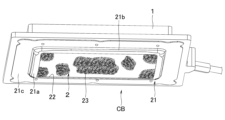
図1及び図2に示すように、水素燃焼バーナCBは、全一次燃焼式のものであり、燃料ガスと一次空気との混合気が供給される混合気室11を有するバーナボディ1と、混合気室11に面するバーナボディ1の開放面12を覆う燃焼板部2とを備える。そして、水素燃焼バーナCBは、バーナボディ1の開放面の12の周縁部、即ち、下面周縁部13にて図外の給湯用の熱交換器が収納される燃焼筐Fbのフランジ部Fb1にネジ(図示せず)により締結され、熱交換器を加熱するために使用される。バーナボディ1にはまた、図外のファンによって混合気が供給される流入口14が開設されている。
As shown in FIGS. 1 and 2, the hydrogen combustion burner CB is of an all-primary combustion type, and includes a
図3も参照して、燃焼板部2は、一方向に長手の額縁状で板金製のバーナ枠21と、バーナ枠21で囲われる矩形の第1開口22をバーナボディ1側(上方)から覆うように設けられる第1の焼結体シート23と、第1の焼結体シート23の混合気の流れ方向上流側の面である裏面(上面)に重ねて配置される、多数の分布孔24aが形成された分布板24とで構成される。バーナ枠21は、第1開口22と同一面上に位置する開口周縁部21aと、開口周縁部21aからバーナボディ1側(上方)に屈曲した側板部21bと、側板部21bの上端から外方に張出す枠フランジ部21cとを有する。そして、第1の焼結体シート23の裏面に分布板24を重ねた状態でこれらの周縁部をバーナ枠21の開口周縁部21aに一定間隔でスポット溶接することで組み立てられている。この状態で、枠フランジ部21cを介してバーナボディ1の下面周縁部13に取り付けられる。なお、第1開口22は、前後方向に沿う断面形状が円弧状に湾曲している。同様に、第1の焼結体シート23及び分布板24も前後方向に沿う断面形状が円弧状に湾曲、言い換えると、混合気の流れ方向下流側に向けて凸の湾曲形状に成形されている。
Referring also to FIG. 3, the
第1の焼結体シート23は、金属繊維23aを織成したり、編成したりすることなく積層した積層体を焼結したものである。金属繊維23aとしては、Feと、Al、Cr、Mn及びSiから選択される少なくとも1種またはこれらの炭化物とで構成されるもの、例えば、Feを主成分とするステンレス系のものが用いられ、その線径が50μm~100μmの範囲のものが用いられる。第1の焼結体シート23の製作には、例えば、加圧成形と焼結とを同時に実施するホットプレス(熱間加工法)や、HIP(Hot Isostatic Pressing)といった公知の方法を利用することができる。例えば、ホットプレスにより製作する場合には、特に図示して説明しないが、金型のキャビティ内に、金属繊維23aを織成したり、編成したりすることなく積層して積層体とする。このとき、目付量が1200g/m2~1800g/m2の範囲に設定される。次に、パンチによって積層体に対して一軸方向から圧力を加え、この状態で金型を介して積層体を所定温度に加熱保持する。このとき、第1の焼結体シート23は混合気の流れ方向下流側に向けて凸の湾曲形状に成形される。
The first sintered
以上のように製作される第1の焼結体シート23は、図3中に一部拡大して示すように、焼結時に金属繊維23aがランダムに絡み合って結合(溶着)することで、複雑で且つ逆火限界の孔径より小さい無数の微小隙間23bが形成されたものとなり、上記従来例のものと比較して金属繊維23a同士の接触箇所が少なく、また、接触箇所の面積も小さくなる。この場合、第1の焼結体シート23が60%~80%の範囲の空隙率を持つと共に0.5mm~3.0mmの板厚を持つ。なお、金属繊維の線径が50μmより小さいと、焼結時に金属繊維同士が絡み合う(接触する)面積が増加して第1の焼結体シート23の裏面側へ熱が伝わり易くなる一方で、その線径が100μmより大きくなると、各微小隙間23bが大きくなり過ぎて逆火を抑制できない虞がある。また、目付量が1200g/m2より少ないと、各微小隙間23bが大きくなり過ぎて逆火を抑制できない虞がある一方で、1800g/m2より多くなると、上記範囲内の空隙率が得られず、混合気の通過抵抗が大きくなる。また、空隙率が上記範囲から外れると、混合気が第1の焼結体シート23を通過するときの圧力損失が大きくなってしまう。
The first sintered
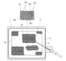
図4も参照して、混合気室11内には、逆火抑制板部3が配置されている。逆火抑制板部3は、一方向に長手の額縁状で板金製の支持枠31と、支持枠31で囲われる、第1開口22と同等の輪郭を持つ第2開口32を燃焼板部2と反対側(上方)から覆うように設けられる第2の焼結体シート33とを備える。第2の焼結体シート33としては、第1の焼結体シート23と同様に製作したものを利用することができる。そして、支持枠31を介して、混合気室11内に形成される額縁状の座面15にネジ(図示せず)により締結される。逆火抑制板部3の締結状態では、第2の焼結体シート33が第1の焼結体シート23に対し隙間Gpを存して対向するようになる。第1及び第2の両焼結体シート23、33相互の間の隙間Gpは5mm~30mmの範囲に設定される。上記間隔が5mmより短いと、燃焼板部2が火炎で加熱されたときに燃焼板部2からの輻射熱が優勢となって逆火抑制板部3が過熱される虞がある一方で、30mmより長くなると、燃焼板部2と逆火抑制板部3との間の隙間Gpに留まる混合気の量が多くなり、当該隙間Gpに火炎が伝播したときに大きな音が発生してしまう。
Referring also to FIG. 4, a flashback
上記水素燃焼バーナCBでは、バーナボディ1の流入口14から混合気室11内に供給された混合気が、第2の焼結体シート33の無数の微小隙間33bを通って燃焼板部2へと供給される。そして、逆火抑制板部3の第2の焼結体シート33を通過した混合気が燃焼板部2と逆火抑制板部3との隙間Gpを通って燃焼板部2の第1の焼結体シート23の各微小隙間23bから噴出して全一次燃焼(二次空気が不要な燃焼)する。これにより、燃焼板部2の表面近くで混合気が燃焼することで第1の焼結体シート23の表面側が高温になったとしても、その熱が混合気室11に面する第1の焼結体シート23の裏面側へと伝わり難くすることができる。しかも、無数の微小隙間23bを通って常温の混合気が噴出される際に、当該混合気との接触面積が大きくなることで、第1の焼結体シート23自体の温度上昇も抑制される。結果として、第1の焼結体シート23には微小隙間しかないことと、第1の焼結体シート23の裏面側が高温になり難いこととが相俟って、逆火を効果的に抑制することができる。また、第1の焼結体シート23を混合気の流れ方向下流側に向けて凸の湾曲形状に成形しておけば、第1の焼結体シート23の燃焼面側が加熱されたときに、焼結体シート23自体が歪み難くでき、焼結体シート23が局所的に高温になって逆火することも抑制できる。
In the hydrogen combustion burner CB, the air-fuel mixture supplied into the air-
また、常温の混合気が第2の焼結体シート33を通過する際には、同様に、混合気との接触面積が大きくなることで、第2の焼結体シート33、即ち、逆火抑制板部3自体の温度上昇が抑制される。しかも、微小隙間33bが無数に形成されていることで、圧力損失も抑制される。このため、仮に燃焼板部2と逆火抑制板部3との間の隙間Gpに火炎が伝播したとしても、逆火抑制板部3の温度上昇が抑制されているため、逆火抑制板部3で消炎させることができる。更に、隙間Gpに伝播した火炎が消炎されないで残る場合でも、逆火抑制板部3には微小隙間33bしかないことで、その上流側への伝播が抑制される。結果として、逆火抑制板部3を更に配置しておけば、逆火を確実に抑制することができる。
Furthermore, when the air-fuel mixture at room temperature passes through the
更に、水素燃焼バーナCBでは、燃焼板部2と逆火抑制板部3との間に位置する混合気室11の部分に温度センサ4が配置されている。温度センサ4としては、熱電対やバイメタルスイッチといった公知のものを利用することができる。これにより、仮に上記隙間Gpに伝播した火炎が消炎されず、隙間Gpに面する第2の焼結体シート33表面(下面)で燃焼する場合に、これに伴う温度上昇を温度センサ4によって検知し、例えば、混合気の供給を停止することで、水素燃焼バーナCBの破損を招く燃焼を速やかに停止することができる。
Furthermore, in the hydrogen combustion burner CB, a
以上、本発明の実施形態について説明したが、本発明の技術思想の範囲を逸脱しない限り、種々の変形が可能である。上記実施形態では、逆火抑制板部3やセンサ4を更に配置したものを例に説明したが、例えば、混合気に少量の還元剤を添加して火炎温度を低下させるような場合には、逆火抑制板部3やセンサ4といった部品は省略することができる。
Although the embodiments of the present invention have been described above, various modifications can be made without departing from the scope of the technical idea of the present invention. In the above embodiment, the
CB…水素燃焼バーナ、1…バーナボディ、11…混合気室、12…開放面、2…燃焼板部、23…焼結体シート、23a…金属繊維。
CB...Hydrogen combustion burner, 1...Burner body, 11...Mixture chamber, 12...Open surface, 2...Combustion plate portion, 23...Sintered compact sheet, 23a...Metal fiber.
Claims (5)
-
燃料ガスを水素ガスとし、当該水素ガスと一次空気との混合気が供給される混合気室を有するバーナボディと、前記混合気室に面する前記バーナボディの開放面を覆う燃焼板部とを備え、前記混合気が前記燃焼板部から噴出して燃焼する水素燃焼バーナにおいて、
前記燃焼板部が、金属繊維を織成したり、編成したりすることなく積層した積層体を焼結した焼結体シートを有することを特徴とする水素燃焼バーナ。
A burner body that uses hydrogen gas as fuel gas and has a mixture chamber to which a mixture of the hydrogen gas and primary air is supplied, and a combustion plate portion that covers an open surface of the burner body facing the mixture chamber. A hydrogen combustion burner comprising: a hydrogen combustion burner in which the air-fuel mixture is ejected from the combustion plate portion and burned;
A hydrogen combustion burner characterized in that the combustion plate portion has a sintered sheet obtained by sintering a laminate in which metal fibers are laminated without weaving or knitting. -
前記金属繊維が、Feと、Al、Cr、Mn及びSiから選択される少なくとも1種またはこれらの炭化物とで構成され、前記焼結体シートの焼結時の目付量が1200g/m2~1800g/m2の範囲に設定されることを特徴とする請求項1記載の水素燃焼バーナ。
The metal fiber is composed of Fe and at least one selected from Al, Cr, Mn, and Si or a carbide thereof, and the sintered sheet has a basis weight of 1200 g/m 2 to 1800 g when sintered. 2. The hydrogen combustion burner according to claim 1, wherein the hydrogen combustion burner is set in a range of / m2 . -
前記金属繊維として、その線径が50μm~100μmの範囲のものを用いることを特徴とする請求項2記載の水素燃焼バーナ。
3. The hydrogen combustion burner according to claim 2, wherein the metal fiber has a wire diameter in the range of 50 μm to 100 μm. -
前記焼結体シートが60%~80%の範囲の空隙率を持つことを特徴とする請求項1記載の水素燃焼バーナ。
A hydrogen combustion burner according to claim 1, characterized in that said sintered sheet has a porosity in the range of 60% to 80%. -
前記焼結体シートが前記混合気の流れ方向下流側に向けて凸の湾曲形状に成形されることを特徴とする請求項1記載の水素燃焼バーナ。
The hydrogen combustion burner according to claim 1, wherein the sintered sheet is formed into a curved shape convex toward the downstream side in the flow direction of the air-fuel mixture.
Applications Claiming Priority (2)
| Application Number | Priority Date | Filing Date | Title |
|---|---|---|---|
| JP2022086443A JP2023173900A (en) | 2022-05-26 | 2022-05-26 | hydrogen combustion burner |
| JP2022-086443 | 2022-05-26 |
Publications (1)
| Publication Number | Publication Date |
|---|---|
| WO2023228441A1 true WO2023228441A1 (en) | 2023-11-30 |
Family
ID=88918896
Family Applications (1)
| Application Number | Title | Priority Date | Filing Date |
|---|---|---|---|
| PCT/JP2022/042076 WO2023228441A1 (en) | 2022-05-26 | 2022-11-11 | Hydrogen combustion burner |
Country Status (2)
| Country | Link |
|---|---|
| JP (1) | JP2023173900A (en) |
| WO (1) | WO2023228441A1 (en) |
Citations (4)
| Publication number | Priority date | Publication date | Assignee | Title |
|---|---|---|---|---|
| JP2000018525A (en) * | 1998-06-26 | 2000-01-18 | Iwatani Internatl Corp | Hydrogen surface combustion burner |
| JP2000283409A (en) * | 1999-03-31 | 2000-10-13 | Nippon Mitsubishi Oil Corp | Method for burning liquid fuel and liquid fuel combustion burner |
| JP2003073711A (en) * | 2001-09-07 | 2003-03-12 | Nhk Spring Co Ltd | Method for manufacturing porous body of metallic fiber |
| JP2020134086A (en) * | 2019-02-25 | 2020-08-31 | リンナイ株式会社 | All primary combustion burner |
-
2022
- 2022-05-26 JP JP2022086443A patent/JP2023173900A/en active Pending
- 2022-11-11 WO PCT/JP2022/042076 patent/WO2023228441A1/en unknown
Patent Citations (4)
| Publication number | Priority date | Publication date | Assignee | Title |
|---|---|---|---|---|
| JP2000018525A (en) * | 1998-06-26 | 2000-01-18 | Iwatani Internatl Corp | Hydrogen surface combustion burner |
| JP2000283409A (en) * | 1999-03-31 | 2000-10-13 | Nippon Mitsubishi Oil Corp | Method for burning liquid fuel and liquid fuel combustion burner |
| JP2003073711A (en) * | 2001-09-07 | 2003-03-12 | Nhk Spring Co Ltd | Method for manufacturing porous body of metallic fiber |
| JP2020134086A (en) * | 2019-02-25 | 2020-08-31 | リンナイ株式会社 | All primary combustion burner |
Also Published As
| Publication number | Publication date |
|---|---|
| JP2023173900A (en) | 2023-12-07 |
Similar Documents
| Publication | Publication Date | Title |
|---|---|---|
| US6896512B2 (en) | Radiator element | |
| US9360210B2 (en) | Combustion method with cool flame base | |
| JPH10160128A (en) | Gas burner | |
| WO2023228441A1 (en) | Hydrogen combustion burner | |
| JP2021179277A (en) | Totally primary combustion type burner | |
| WO2023228440A1 (en) | Totally aerated combustion burner | |
| JP5857502B2 (en) | Combustion heater | |
| JP7181120B2 (en) | Full primary combustion burner | |
| JP3685554B2 (en) | Original mixed surface flame type burner | |
| JP2697155B2 (en) | Burner plate | |
| JP2751425B2 (en) | Burner plate | |
| JP6931118B2 (en) | Burner noise reduction | |
| JP2751426B2 (en) | Burner plate | |
| US20220170631A1 (en) | Combustion membrane for a gas burner | |
| JP2017020678A (en) | Cooking stove | |
| JPH0328609A (en) | Burner plate | |
| JP2000130715A (en) | Burner | |
| JP2977449B2 (en) | Surface burner | |
| JP2697157B2 (en) | Burner plate | |
| JP2977448B2 (en) | Surface burner | |
| JP2023173899A5 (en) | ||
| JPH08170813A (en) | Surface combustion burner device | |
| JP2002228120A (en) | Combustion plate and surface combustion burner having the combustion plate | |
| BE1005992A4 (en) | Water permeable membrane for surface radiation burner | |
| JP2568534B2 (en) | Burner |
Legal Events
| Date | Code | Title | Description |
|---|---|---|---|
| 121 | Ep: the epo has been informed by wipo that ep was designated in this application |
Ref document number: 22943840 Country of ref document: EP Kind code of ref document: A1 |