WO2023227992A1 - 半導体装置 - Google Patents
半導体装置 Download PDFInfo
- Publication number
- WO2023227992A1 WO2023227992A1 PCT/IB2023/054909 IB2023054909W WO2023227992A1 WO 2023227992 A1 WO2023227992 A1 WO 2023227992A1 IB 2023054909 W IB2023054909 W IB 2023054909W WO 2023227992 A1 WO2023227992 A1 WO 2023227992A1
- Authority
- WO
- WIPO (PCT)
- Prior art keywords
- layer
- insulating layer
- semiconductor
- conductive layer
- conductive
- Prior art date
- Legal status (The legal status is an assumption and is not a legal conclusion. Google has not performed a legal analysis and makes no representation as to the accuracy of the status listed.)
- Ceased
Links
Images



























Classifications
-
- H—ELECTRICITY
- H10—SEMICONDUCTOR DEVICES; ELECTRIC SOLID-STATE DEVICES NOT OTHERWISE PROVIDED FOR
- H10D—INORGANIC ELECTRIC SEMICONDUCTOR DEVICES
- H10D30/00—Field-effect transistors [FET]
- H10D30/60—Insulated-gate field-effect transistors [IGFET]
- H10D30/67—Thin-film transistors [TFT]
- H10D30/6728—Vertical TFTs
-
- H—ELECTRICITY
- H10—SEMICONDUCTOR DEVICES; ELECTRIC SOLID-STATE DEVICES NOT OTHERWISE PROVIDED FOR
- H10D—INORGANIC ELECTRIC SEMICONDUCTOR DEVICES
- H10D30/00—Field-effect transistors [FET]
- H10D30/60—Insulated-gate field-effect transistors [IGFET]
- H10D30/67—Thin-film transistors [TFT]
- H10D30/674—Thin-film transistors [TFT] characterised by the active materials
- H10D30/6755—Oxide semiconductors, e.g. zinc oxide, copper aluminium oxide or cadmium stannate
-
- H—ELECTRICITY
- H10—SEMICONDUCTOR DEVICES; ELECTRIC SOLID-STATE DEVICES NOT OTHERWISE PROVIDED FOR
- H10K—ORGANIC ELECTRIC SOLID-STATE DEVICES
- H10K59/00—Integrated devices, or assemblies of multiple devices, comprising at least one organic light-emitting element covered by group H10K50/00
- H10K59/10—OLED displays
- H10K59/12—Active-matrix OLED [AMOLED] displays
- H10K59/121—Active-matrix OLED [AMOLED] displays characterised by the geometry or disposition of pixel elements
- H10K59/1213—Active-matrix OLED [AMOLED] displays characterised by the geometry or disposition of pixel elements the pixel elements being TFTs
-
- G—PHYSICS
- G02—OPTICS
- G02F—OPTICAL DEVICES OR ARRANGEMENTS FOR THE CONTROL OF LIGHT BY MODIFICATION OF THE OPTICAL PROPERTIES OF THE MEDIA OF THE ELEMENTS INVOLVED THEREIN; NON-LINEAR OPTICS; FREQUENCY-CHANGING OF LIGHT; OPTICAL LOGIC ELEMENTS; OPTICAL ANALOGUE/DIGITAL CONVERTERS
- G02F1/00—Devices or arrangements for the control of the intensity, colour, phase, polarisation or direction of light arriving from an independent light source, e.g. switching, gating or modulating; Non-linear optics
- G02F1/01—Devices or arrangements for the control of the intensity, colour, phase, polarisation or direction of light arriving from an independent light source, e.g. switching, gating or modulating; Non-linear optics for the control of the intensity, phase, polarisation or colour
- G02F1/13—Devices or arrangements for the control of the intensity, colour, phase, polarisation or direction of light arriving from an independent light source, e.g. switching, gating or modulating; Non-linear optics for the control of the intensity, phase, polarisation or colour based on liquid crystals, e.g. single liquid crystal display cells
- G02F1/133—Constructional arrangements; Operation of liquid crystal cells; Circuit arrangements
- G02F1/136—Liquid crystal cells structurally associated with a semi-conducting layer or substrate, e.g. cells forming part of an integrated circuit
- G02F1/1362—Active matrix addressed cells
- G02F1/1368—Active matrix addressed cells in which the switching element is a three-electrode device
-
- H—ELECTRICITY
- H10—SEMICONDUCTOR DEVICES; ELECTRIC SOLID-STATE DEVICES NOT OTHERWISE PROVIDED FOR
- H10D—INORGANIC ELECTRIC SEMICONDUCTOR DEVICES
- H10D30/00—Field-effect transistors [FET]
- H10D30/60—Insulated-gate field-effect transistors [IGFET]
- H10D30/67—Thin-film transistors [TFT]
- H10D30/6757—Thin-film transistors [TFT] characterised by the structure of the channel, e.g. transverse or longitudinal shape or doping profile
-
- H—ELECTRICITY
- H10—SEMICONDUCTOR DEVICES; ELECTRIC SOLID-STATE DEVICES NOT OTHERWISE PROVIDED FOR
- H10D—INORGANIC ELECTRIC SEMICONDUCTOR DEVICES
- H10D86/00—Integrated devices formed in or on insulating or conducting substrates, e.g. formed in silicon-on-insulator [SOI] substrates or on stainless steel or glass substrates
- H10D86/40—Integrated devices formed in or on insulating or conducting substrates, e.g. formed in silicon-on-insulator [SOI] substrates or on stainless steel or glass substrates characterised by multiple TFTs
-
- H—ELECTRICITY
- H10—SEMICONDUCTOR DEVICES; ELECTRIC SOLID-STATE DEVICES NOT OTHERWISE PROVIDED FOR
- H10H—INORGANIC LIGHT-EMITTING SEMICONDUCTOR DEVICES HAVING POTENTIAL BARRIERS
- H10H29/00—Integrated devices, or assemblies of multiple devices, comprising at least one light-emitting semiconductor element covered by group H10H20/00
- H10H29/10—Integrated devices comprising at least one light-emitting semiconductor component covered by group H10H20/00
- H10H29/14—Integrated devices comprising at least one light-emitting semiconductor component covered by group H10H20/00 comprising multiple light-emitting semiconductor components
-
- H—ELECTRICITY
- H10—SEMICONDUCTOR DEVICES; ELECTRIC SOLID-STATE DEVICES NOT OTHERWISE PROVIDED FOR
- H10K—ORGANIC ELECTRIC SOLID-STATE DEVICES
- H10K59/00—Integrated devices, or assemblies of multiple devices, comprising at least one organic light-emitting element covered by group H10K50/00
- H10K59/10—OLED displays
-
- H—ELECTRICITY
- H10—SEMICONDUCTOR DEVICES; ELECTRIC SOLID-STATE DEVICES NOT OTHERWISE PROVIDED FOR
- H10K—ORGANIC ELECTRIC SOLID-STATE DEVICES
- H10K59/00—Integrated devices, or assemblies of multiple devices, comprising at least one organic light-emitting element covered by group H10K50/00
- H10K59/10—OLED displays
- H10K59/12—Active-matrix OLED [AMOLED] displays
- H10K59/124—Insulating layers formed between TFT elements and OLED elements
-
- H—ELECTRICITY
- H10—SEMICONDUCTOR DEVICES; ELECTRIC SOLID-STATE DEVICES NOT OTHERWISE PROVIDED FOR
- H10H—INORGANIC LIGHT-EMITTING SEMICONDUCTOR DEVICES HAVING POTENTIAL BARRIERS
- H10H29/00—Integrated devices, or assemblies of multiple devices, comprising at least one light-emitting semiconductor element covered by group H10H20/00
- H10H29/30—Active-matrix LED displays
- H10H29/32—Active-matrix LED displays characterised by the geometry or arrangement of elements within a subpixel, e.g. arrangement of the transistor within its RGB subpixel
-
- H—ELECTRICITY
- H10—SEMICONDUCTOR DEVICES; ELECTRIC SOLID-STATE DEVICES NOT OTHERWISE PROVIDED FOR
- H10K—ORGANIC ELECTRIC SOLID-STATE DEVICES
- H10K59/00—Integrated devices, or assemblies of multiple devices, comprising at least one organic light-emitting element covered by group H10K50/00
- H10K59/10—OLED displays
- H10K59/12—Active-matrix OLED [AMOLED] displays
Definitions
- One embodiment of the present invention relates to a semiconductor device and a method for manufacturing the same.
- One embodiment of the present invention relates to a transistor and a method for manufacturing the same.
- One embodiment of the present invention relates to a display device including a semiconductor device.
- one embodiment of the present invention is not limited to the above technical field.
- the technical fields of one embodiment of the present invention include semiconductor devices, display devices, light-emitting devices, power storage devices, storage devices, electronic devices, lighting devices, input devices (e.g., touch sensors), input/output devices (e.g., touch panels), and the like.
- An example of this is a method for driving the same or a method for producing the same.
- a semiconductor device is a device that utilizes semiconductor characteristics, and refers to a circuit including a semiconductor element (transistor, diode, photodiode, etc.), a device having the same circuit, etc. It also refers to any device that can function by utilizing the characteristics of semiconductors.
- an integrated circuit, a chip including an integrated circuit, and an electronic component containing a chip in a package are examples of semiconductor devices.
- a storage device, a display device, a light emitting device, a lighting device, and an electronic device may themselves be semiconductor devices, and each may include a semiconductor device.
- Semiconductor devices having transistors are widely applied to electronic devices. For example, in a display device, by reducing the area occupied by a transistor, the pixel size can be reduced and the definition can be improved. Therefore, miniaturized transistors are required.
- Examples of devices that require high-definition display devices include virtual reality (VR), augmented reality (AR), substitute reality (SR), and mixed reality (MR). ) devices are being actively developed.
- VR virtual reality
- AR augmented reality
- SR substitute reality
- MR mixed reality
- a display device for example, a light emitting device having an organic EL (Electro Luminescence) element or a light emitting diode (LED) has been developed.
- organic EL Electro Luminescence
- LED light emitting diode
- Patent Document 1 discloses a high-definition display device using organic EL elements.
- An object of one embodiment of the present invention is to provide a microsized transistor.
- one of the challenges is to provide a transistor with a short channel length.
- one of the objects is to provide a semiconductor device that occupies a small area.
- one of the objects is to provide a semiconductor device with low wiring resistance.
- Another object of the present invention is to provide a semiconductor device or a display device with low power consumption.
- one object of the present invention is to provide a highly reliable transistor, semiconductor device, or display device.
- one of the challenges is to provide a high-definition display device.
- Another object of the present invention is to provide a method for manufacturing a semiconductor device or a display device with high productivity.
- Another object of the present invention is to provide a novel transistor, a semiconductor device, a display device, or a manufacturing method thereof.
- One embodiment of the present invention includes a first semiconductor layer, a second semiconductor layer, a first conductive layer, a second conductive layer, a third conductive layer, a first insulating layer, and a first conductive layer.
- This is a semiconductor device having two insulating layers.
- a first insulating layer is provided on the first conductive layer.
- a second conductive layer is provided on the first insulating layer.
- the first insulating layer and the second conductive layer have openings that reach the first conductive layer.
- the first semiconductor layer is in contact with the top surface of the first conductive layer, the side surface of the first insulating layer, and the top surface and side surfaces of the second conductive layer.
- the second semiconductor layer is provided on the first semiconductor layer.
- a second insulating layer is provided on the second semiconductor layer.
- a third conductive layer is provided on the second insulating layer. The conductivity of the first semiconductor layer is different from the conductivity of the second semiconductor layer.
- One embodiment of the present invention includes a first semiconductor layer, a second semiconductor layer, a first conductive layer, a second conductive layer, a third conductive layer, a first insulating layer, and a first conductive layer.
- This is a semiconductor device having two insulating layers.
- a first insulating layer is provided on the first conductive layer.
- a second conductive layer is provided on the first insulating layer.
- the first insulating layer and the second conductive layer have openings that reach the first conductive layer.
- the first semiconductor layer is in contact with the top surface of the first conductive layer, the side surface of the first insulating layer, and the top surface and side surfaces of the second conductive layer.
- the second semiconductor layer is provided on the first semiconductor layer.
- a second insulating layer is provided on the second semiconductor layer.
- a third conductive layer is provided on the second insulating layer. The conductivity of the first semiconductor layer is higher than the conductivity of the second semiconductor layer.
- One embodiment of the present invention includes a first semiconductor layer, a second semiconductor layer, a first conductive layer, a second conductive layer, a third conductive layer, a first insulating layer, and a first conductive layer.
- This is a semiconductor device having two insulating layers.
- a first insulating layer is provided on the first conductive layer.
- a second conductive layer is provided on the first insulating layer.
- the first insulating layer and the second conductive layer have openings that reach the first conductive layer.
- the first semiconductor layer is in contact with the top surface of the first conductive layer, the side surface of the first insulating layer, and the top surface and side surfaces of the second conductive layer.
- the second semiconductor layer is provided on the first semiconductor layer.
- a second insulating layer is provided on the second semiconductor layer.
- a third conductive layer is provided on the second insulating layer.
- the first semiconductor layer includes a first metal oxide.
- the second semiconductor layer includes a second metal oxide.
- One embodiment of the present invention includes a first semiconductor layer, a second semiconductor layer, a first conductive layer, a second conductive layer, a third conductive layer, a first insulating layer, and a first conductive layer.
- This is a semiconductor device having two insulating layers.
- a first insulating layer is provided on the first conductive layer.
- a second conductive layer is provided on the first insulating layer.
- the first insulating layer and the second conductive layer have openings that reach the first conductive layer.
- the first semiconductor layer is in contact with the top surface of the first conductive layer, the side surface of the first insulating layer, and the top surface and side surfaces of the second conductive layer.
- the second semiconductor layer is provided on the first semiconductor layer.
- a second insulating layer is provided on the second semiconductor layer.
- a third conductive layer is provided on the second insulating layer.
- the first semiconductor layer includes a first metal oxide.
- the second semiconductor layer includes a second metal oxide.
- the first metal oxide contains indium.
- the second metal oxide contains indium and element M.
- Element M is one or more of gallium, aluminum, and tin. The content of element M in the first metal oxide is lower than the content of element M in the second metal oxide.
- One embodiment of the present invention includes a first semiconductor layer, a second semiconductor layer, a first conductive layer, a second conductive layer, a third conductive layer, a first insulating layer, and a first conductive layer.
- This is a semiconductor device having two insulating layers.
- a first insulating layer is provided on the first conductive layer.
- a second conductive layer is provided on the first insulating layer.
- the first insulating layer and the second conductive layer have openings that reach the first conductive layer.
- the first semiconductor layer is in contact with the top surface of the first conductive layer, the side surface of the first insulating layer, and the top surface and side surfaces of the second conductive layer.
- the second semiconductor layer is provided on the first semiconductor layer.
- a second insulating layer is provided on the second semiconductor layer.
- a third conductive layer is provided on the second insulating layer.
- the first semiconductor layer and the second semiconductor layer each include a metal oxide.
- the crystallinity of the first semiconductor layer is lower
- the first conductive layer and the second conductive layer each contain an oxide conductor.
- the first insulating layer includes a third insulating layer, a fourth insulating layer on the third insulating layer, and a fifth insulating layer on the fourth insulating layer. It is preferable.
- the fourth insulating layer contains oxygen. It is preferable that the third insulating layer and the fifth insulating layer each contain nitrogen.
- the first insulating layer includes a third insulating layer, a fourth insulating layer on the third insulating layer, a fifth insulating layer on the fourth insulating layer, and a fifth insulating layer. It is preferable to have a sixth insulating layer on the insulating layer.
- the fifth insulating layer contains oxygen.
- the third insulating layer, the fourth insulating layer, and the sixth insulating layer each contain nitrogen.
- the third insulating layer has a region containing more hydrogen than the fourth insulating layer.
- the aforementioned semiconductor device preferably includes a fourth conductive layer.
- the fourth conductive layer has a region in contact with the upper surface of the first conductive layer.
- the first insulating layer preferably has a region in contact with the top surface of the first conductive layer and the top surface and side surfaces of the fourth conductive layer.
- the fourth conductive layer preferably has a region that overlaps with the third conductive layer via the first insulating layer, the first semiconductor layer, the second semiconductor layer, and the second insulating layer.
- the conductivity of the fourth conductive layer is preferably higher than the conductivity of the first conductive layer.
- a microsized transistor can be provided.
- a transistor with a short channel length can be provided.
- a transistor with a large on-state current can be provided.
- a transistor with a small cutoff current can be provided.
- a transistor with good electrical characteristics can be provided.
- a semiconductor device that occupies a small area can be provided.
- a semiconductor device with low wiring resistance can be provided.
- a semiconductor device or display device with low power consumption can be provided.
- a highly reliable transistor, semiconductor device, or display device can be provided.
- a high-definition display device can be provided.
- a method for manufacturing a semiconductor device or a display device with high productivity can be provided.
- a novel transistor, a semiconductor device, a display device, or a manufacturing method thereof can be provided.
- FIG. 1A is a top view showing an example of a semiconductor device.
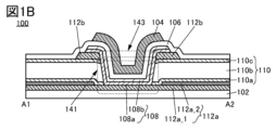
- 1B and 1C are cross-sectional views showing an example of a semiconductor device.
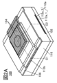
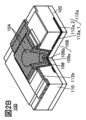
- 2A to 2D are perspective views showing an example of a semiconductor device.
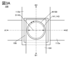
- FIG. 3A is a top view showing an example of a semiconductor device.
- FIG. 3B is a cross-sectional view showing an example of a semiconductor device.
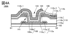
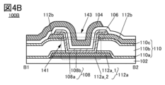
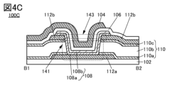
- 4A to 4C are cross-sectional views showing an example of a semiconductor device.
- 5A and 5B are cross-sectional views showing an example of a semiconductor device.
- 6A and 6B are cross-sectional views showing an example of a semiconductor device.
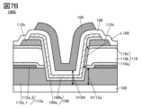
- 7A and 7B are cross-sectional views showing an example of a semiconductor device.
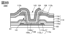
- FIG. 8A and 8B are cross-sectional views showing an example of a semiconductor device.
- FIG. 9 is a cross-sectional view showing an example of a semiconductor device.
- FIG. 10A is a top view showing an example of a semiconductor device.
- FIG. 10B is a cross-sectional view showing an example of a semiconductor device.
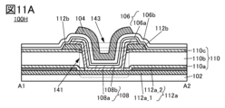
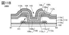
- 11A and 11B are cross-sectional views showing an example of a semiconductor device.
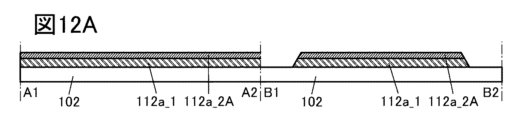
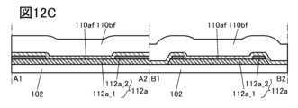
- 12A to 12D are cross-sectional views showing an example of a method for manufacturing a semiconductor device.
- 13A to 13C are cross-sectional views illustrating an example of a method for manufacturing a semiconductor device.
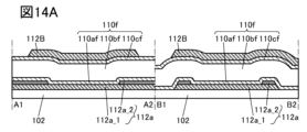
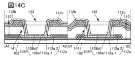
- 14A to 14C are cross-sectional views showing an example of a method for manufacturing a semiconductor device.
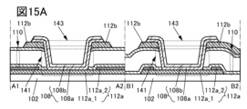
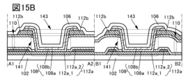
- FIG. 15A and 15B are cross-sectional views showing an example of a method for manufacturing a semiconductor device.
- FIG. 16 is a perspective view showing an example of a display device.
- FIG. 17 is a cross-sectional view showing an example of a display device.
- FIG. 18 is a cross-sectional view showing an example of a display device.
- FIG. 19 is a cross-sectional view showing an example of a display device.
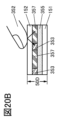
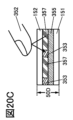
- 20A to 20C are cross-sectional views showing an example of a display device.
- FIG. 21 is a cross-sectional view showing an example of a display device.
- FIG. 22 is a cross-sectional view showing an example of a display device.
- FIG. 23 is a cross-sectional view showing an example of a display device.
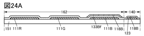
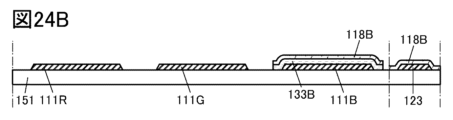
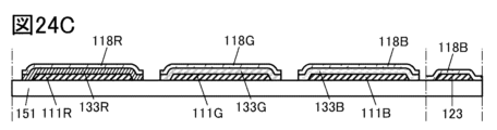
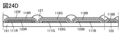
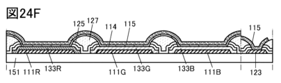
- 24A to 24F are cross-sectional views illustrating an example of a method for manufacturing a display device.
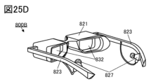
- 25A to 25D are diagrams illustrating an example of an electronic device.
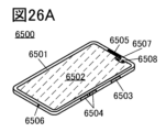
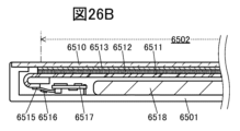
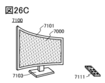
- 26A to 26F are diagrams illustrating an example of an electronic device.
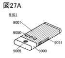
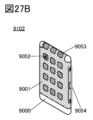
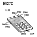
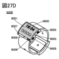
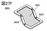
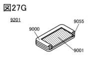
- 27A to 27G are diagrams illustrating an example of an electronic device.
- 28A and 28B are diagrams showing Id-Vg characteristics of a transistor.
- 29A and 29B are diagrams showing Id-Vg characteristics of a transistor.
- ordinal numbers such as “first” and “second” are used for convenience, and do not limit the number of components or the order of the components (for example, the order of steps or the order of lamination). It's not something you do. Further, the ordinal number attached to a constituent element in a certain part of this specification may not match the ordinal number attached to the constituent element in another part of this specification or in the claims.
- film and “layer” can be interchanged depending on the situation or circumstances.
- conductive layer can be changed to the term “conductive film.”
- insulating film can be changed to the term “insulating layer.”
- a transistor is a type of semiconductor element, and can achieve the function of amplifying current or voltage, and the switching operation of controlling conduction or non-conduction.
- Transistors in this specification include IGFETs (Insulated Gate Field Effect Transistors) and thin film transistors (TFTs).
- source and drain may be interchanged when transistors of different polarity are employed, or when the direction of current changes during circuit operation. Therefore, in this specification and the like, the terms “source” and “drain” can be used interchangeably.
- electrically connected includes a case where a connection is made via "something that has some kind of electrical effect.”
- something that has some kind of electrical effect is not particularly limited as long as it enables transmission and reception of electrical signals between connected objects.
- something that has some kind of electrical action includes electrodes or wiring, switching elements such as transistors, resistance elements, coils, capacitance elements, and other elements with various functions.
- off-state current refers to leakage current between a source and a drain when a transistor is in an off state (also referred to as a non-conducting state or a cutoff state).
- an off state is a state in which the voltage between the gate and source, V gs , is lower than the threshold voltage V th for n-channel transistors (higher than V th for p-channel transistors). means.
- the upper surface shapes roughly match means that at least a portion of the outlines of the stacked layers overlap. For example, this includes a case where the upper layer and the lower layer are processed using the same mask pattern or partially the same mask pattern. However, strictly speaking, the contours may not overlap, and the upper layer may be located inside the lower layer, or the upper layer may be located outside the lower layer, and in this case, the upper surface shape may be said to be "approximately the same”. Furthermore, when the top surface shapes match or roughly match, it can also be said that the ends are aligned or roughly aligned.
- a tapered shape refers to a shape in which at least a part of the side surface of the structure is inclined with respect to the substrate surface or the surface to be formed.
- a region where the angle between the inclined side surface and the substrate surface or the surface to be formed also referred to as a taper angle
- the side surface of the structure, the substrate surface, and the surface to be formed do not necessarily have to be completely flat, and may be substantially planar with a minute curvature or substantially planar with minute irregularities.
- a device manufactured using a metal mask or FMM fine metal mask, high-definition metal mask
- a device with a MM (metal mask) structure is sometimes referred to as a device with an MML (metal maskless) structure.
- SBS Side By Side
- materials and configurations can be optimized for each light emitting element, which increases the degree of freedom in selecting materials and configurations, making it easier to improve brightness and reliability.
- holes or electrons are sometimes referred to as “carriers.”
- a hole injection layer or an electron injection layer is called a “carrier injection layer”
- a hole transport layer or an electron transport layer is called a “carrier transport layer”
- a hole blocking layer or an electron blocking layer is called a “carrier injection layer.”
- the carrier injection layer, carrier transport layer, and carrier block layer described above may not be clearly distinguishable depending on their respective cross-sectional shapes or characteristics.
- one layer may serve as two or three functions among a carrier injection layer, a carrier transport layer, and a carrier block layer.
- a light emitting element has an EL layer between a pair of electrodes.
- the EL layer has at least a light emitting layer.
- the layers (also referred to as functional layers) included in the EL layer include a light emitting layer, a carrier injection layer (a hole injection layer and an electron injection layer), a carrier transport layer (a hole transport layer and an electron transport layer), and a carrier Block layers (hole block layer and electron block layer) and the like can be mentioned.
- a light receiving element also referred to as a light receiving device
- one of a pair of electrodes is sometimes referred to as a pixel electrode, and the other is sometimes referred to as a common electrode.
- the sacrificial layer (which may also be called a mask layer) refers to at least the layer above the light-emitting layer (more specifically, the layer that is processed into an island shape among the layers constituting the EL layer). It has the function of protecting the light emitting layer during the manufacturing process.
- step breakage refers to a phenomenon in which a layer, film, or electrode is separated due to the shape of the surface on which it is formed (for example, a step difference).
- FIG. 1A shows a top view of transistor 100 in FIG. 1A.
- FIG. 1B shows a cross-sectional view taken along the dashed-dotted line A1-A2 shown in FIG. 1A
- FIG. 1C shows a cross-sectional view taken along the dashed-dotted line B1-B2. Note that in FIG. 1A, some of the components of the transistor 100 (such as a gate insulating layer) are omitted. Regarding the top view of the transistor, some of the constituent elements are omitted in the subsequent drawings as well as in FIG. 1A.
- FIGS. 2A to 2D Perspective views of the transistor 100 are shown in FIGS. 2A to 2D.
- FIG. 2B shows a cross section taken along the dashed line C1-C2 shown in FIG. 2A.
- FIG. 2C the insulating layer shown in FIG. 2A is transparent, and the outline is shown by a broken line.
- FIG. 2D the insulating layer shown in FIG. 2B is transparent and the outline is shown in dashed lines.
- the transistor 100 is provided on a substrate 102.
- the transistor 100 includes a conductive layer 104, an insulating layer 106, a semiconductor layer 108, a conductive layer 112a, and a conductive layer 112b.
- the conductive layer 104 functions as a gate electrode (also referred to as a first gate electrode).
- a portion of the insulating layer 106 functions as a gate insulating layer (also referred to as a first gate insulating layer).
- the conductive layer 112a functions as one of a source electrode and a drain electrode, and the conductive layer 112b functions as the other.
- the semiconductor layer 108 the entire region between the source electrode and the drain electrode that overlaps with the gate electrode via the gate insulating layer functions as a channel formation region. Further, in the semiconductor layer 108, a region in contact with the source electrode functions as a source region, and a region in contact with the drain electrode functions as a drain region.
- a conductive layer 112a is provided on the substrate 102, an insulating layer 110 is provided on the conductive layer 112a, and a conductive layer 112b is provided on the insulating layer 110.
- the insulating layer 110 has a region sandwiched between a conductive layer 112a and a conductive layer 112b.
- the conductive layer 112a has a region overlapping with the conductive layer 112b with the insulating layer 110 interposed therebetween.
- the insulating layer 110 has an opening 141 that reaches the conductive layer 112a. It can also be said that the conductive layer 112a is exposed in the opening 141.
- the conductive layer 112b has an opening 143 in a region overlapping with the conductive layer 112a.
- the opening 143 is provided in a region overlapping with the opening 141.
- the semiconductor layer 108 is provided to cover the openings 141 and 143.
- the semiconductor layer 108 has a region in contact with the top and side surfaces of the conductive layer 112b, the side surfaces of the insulating layer 110, and the top surface of the conductive layer 112a.
- the semiconductor layer 108 is electrically connected to the conductive layer 112a through the opening 141 and the opening 143.
- the semiconductor layer 108 has a shape that follows the top and side surfaces of the conductive layer 112b, the side surfaces of the insulating layer 110, and the top surface of the conductive layer 112a.
- the insulating layer 106 functioning as a gate insulating layer of the transistor 100 is provided to cover the openings 141 and 143.
- the insulating layer 106 is provided over the semiconductor layer 108, the conductive layer 112b, and the insulating layer 110.
- the insulating layer 106 has a region in contact with the top surface and side surfaces of the semiconductor layer 108, the top surface and side surfaces of the conductive layer 112b, and the top surface of the insulating layer 110.
- the insulating layer 106 has a shape that follows the top surface of the insulating layer 110, the top surface and side surfaces of the conductive layer 112b, the top surface and side surfaces of the semiconductor layer 108, and the top surface of the conductive layer 112a.
- a conductive layer 104 functioning as a gate electrode of the transistor 100 is provided on the insulating layer 106 and has a region in contact with the upper surface of the insulating layer 106.
- the conductive layer 104 has a region overlapping with the semiconductor layer 108 with the insulating layer 106 in between.
- the conductive layer 104 has a shape that follows the shape of the upper surface of the insulating layer 106.
- the transistor 100 is a so-called top-gate transistor that has a gate electrode above the semiconductor layer 108. Furthermore, since the lower surface of the semiconductor layer 108 is in contact with the source electrode and the drain electrode, it can be called a TGBC (Top Gate Bottom Contact) transistor.
- the source electrode and the drain electrode are located at different heights with respect to the surface of the substrate 102, which is the surface on which they are formed, and the drain current flows in a direction perpendicular or approximately perpendicular to the surface of the substrate 102. flows. In the transistor 100, the drain current can also be said to flow in the vertical direction or approximately in the vertical direction. Therefore, a transistor that is one embodiment of the present invention can be called a vertical channel transistor or a VFET (Vertical Field Effect Transistor).
- VFET Very Field Effect Transistor
- the channel length of the transistor 100 can be controlled by the thickness of the insulating layer 110 provided between the conductive layer 112a and the conductive layer 112b. Therefore, a transistor having a channel length smaller than the resolution limit of an exposure apparatus used for manufacturing the transistor can be manufactured with high precision. Furthermore, variations in characteristics among the plurality of transistors 100 are also reduced. Therefore, the operation of the semiconductor device including the transistor 100 is stabilized, and reliability can be improved. Furthermore, when characteristic variations are reduced, the degree of freedom in circuit design increases, and the operating voltage of the semiconductor device can be lowered. Therefore, power consumption of the semiconductor device can be reduced.
- the source electrode, the semiconductor layer, and the drain electrode can be provided overlapping each other, so the occupied area is smaller than that of a so-called planar transistor in which the semiconductor layers are arranged in a plane. Can be significantly reduced.
- the conductive layer 112a, the conductive layer 112b, and the conductive layer 104 can each function as wiring, and the transistor 100 can be provided in a region where these wirings overlap. That is, in a circuit including the transistor 100 and the wiring, the area occupied by the transistor 100 and the wiring can be reduced. Therefore, the area occupied by the circuit can be reduced, and a compact semiconductor device can be achieved.
- the semiconductor device of one embodiment of the present invention when the semiconductor device of one embodiment of the present invention is applied to a pixel circuit of a display device, the area occupied by the pixel circuit can be reduced, and a high-definition display device can be obtained. Further, for example, when the semiconductor device of one embodiment of the present invention is applied to a driver circuit of a display device (for example, one or both of a gate line driver circuit and a source line driver circuit), the area occupied by the driver circuit can be reduced. Therefore, a display device with a narrow frame can be obtained.
- a driver circuit of a display device for example, one or both of a gate line driver circuit and a source line driver circuit
- FIG. 1A and the like show an example in which the semiconductor layer 108, the insulating layer 106, and the conductive layer 104 cover the openings 141 and 143, one embodiment of the present invention is not limited to this.
- a structure may be adopted in which a step is formed by the insulating layer 110, the conductive layer 112b, and the conductive layer 112a, and the semiconductor layer 108, the insulating layer 106, and the conductive layer 104 are provided along the step.
- the semiconductor layer 108 has a stacked structure.
- FIG. 1B and the like show a structure in which the semiconductor layer 108 has a stacked structure of a semiconductor layer 108a and a semiconductor layer 108b over the semiconductor layer 108a.
- the conductivity of the material used for the semiconductor layer 108a is preferably different from the conductivity of the material used for the semiconductor layer 108b.
- a material with higher conductivity than the semiconductor layer 108b can be used for the semiconductor layer 108a.
- the contact resistance between the semiconductor layer 108 and the conductive layer 112a and the contact resistance between the semiconductor layer 108 and the conductive layer can be lowered, and the transistor can have a large on-state current.
- the threshold voltage of the transistor shifts and the drain current (hereinafter referred to as cutoff) that flows when the gate voltage is 0V is used. (also referred to as off-state current) may become large.
- the threshold voltage may be low, and when the transistor 100 is a p-channel transistor, the threshold voltage may be high. Therefore, it is preferable to use a material having lower conductivity than the semiconductor layer 108a for the semiconductor layer 108b.
- the threshold voltage can be increased when the transistor 100 is an n-channel transistor, and the threshold voltage can be lowered when the transistor 100 is a p-channel transistor, resulting in a transistor with a small cutoff current. be able to. Note that a small cutoff current is sometimes referred to as normally off.
- the semiconductor layer 108 As described above, by forming the semiconductor layer 108 into a stacked structure and using a material with higher conductivity than the semiconductor layer 108b for the semiconductor layer 108a, a normally-off transistor with a large on-current can be obtained. Therefore, it is possible to provide a semiconductor device that has both low power consumption and high performance.
- the carrier concentration of the semiconductor layer 108a is preferably higher than the carrier concentration of the semiconductor layer 108b.
- the conductivity increases, and the contact resistance between the semiconductor layer 108 and the conductive layer 112a and the contact resistance between the semiconductor layer 108 and the conductive layer 112b can be lowered, and the on-current It is possible to use a transistor with a large value.
- the carrier concentration of the semiconductor layer 108b By lowering the carrier concentration of the semiconductor layer 108b, the conductivity is lowered, and a normally-off transistor can be obtained.
- the semiconductor layer 108a is made of a material with higher conductivity than the semiconductor layer 108b
- one embodiment of the present invention is not limited to this.
- a material having lower conductivity than the semiconductor layer 108b may be used for the semiconductor layer 108a.
- the carrier concentration of the semiconductor layer 108a can be lower than the carrier concentration of the semiconductor layer 108b.
- the semiconductor materials used for the semiconductor layer 108a and the semiconductor layer 108b are not particularly limited.
- a semiconductor made of a single element or a compound semiconductor can be used.
- semiconductors made of simple elements include silicon and germanium.
- compound semiconductors include gallium arsenide and silicon germanium.
- Other examples of compound semiconductors include organic semiconductors, nitride semiconductors, and oxide semiconductors. Note that these semiconductor materials may contain impurities as dopants.
- the crystallinity of the semiconductor material used for the semiconductor layer 108a and the semiconductor layer 108b is not particularly limited, and may be an amorphous semiconductor, a single crystal semiconductor, or a semiconductor having crystallinity other than single crystal (microcrystalline semiconductor, polycrystalline semiconductor, or (a semiconductor partially having a crystalline region) may be used. It is preferable to use a single crystal semiconductor or a semiconductor having crystallinity because deterioration of transistor characteristics can be suppressed.
- the semiconductor layer 108a and the semiconductor layer 108b each include a metal oxide (also referred to as an oxide semiconductor) that exhibits semiconductor characteristics.
- a metal oxide also referred to as an oxide semiconductor
- the band gap of the first metal oxide used for the semiconductor layer 108a and the second metal oxide used for the semiconductor layer 108b is preferably 2.0 eV or more, and more preferably 2.5 eV or more.
- the band gap of the first metal oxide used for the semiconductor layer 108a is preferably different from the band gap of the second metal oxide used for the semiconductor layer 108b.
- the difference between the band gap of the first metal oxide and the band gap of the second metal oxide is preferably 0.1 eV or more, more preferably 0.2 eV or more, and even more preferably 0.3 eV or more.
- the bandgap of the first metal oxide used for the semiconductor layer 108a can be configured to be smaller than the bandgap of the second metal oxide used for the semiconductor layer 108b. Accordingly, the contact resistance between the semiconductor layer 108 and the conductive layer 112a and the contact resistance between the semiconductor layer 108 and the conductive layer 112b can be reduced, and a transistor with a large on-state current can be obtained. Further, when the transistor 100 is an n-channel transistor, the threshold voltage can be set high, and when the transistor 100 is a p-channel transistor, the threshold voltage can be set low, so that the transistor 100 can be a normally-off transistor.
- the band gap of the first metal oxide is smaller than the band gap of the second metal oxide
- one embodiment of the present invention is not limited to this.
- the first metal oxide may have a larger band gap than the second metal oxide.
- the first metal oxide and the second metal oxide include indium oxide, gallium oxide, and zinc oxide.
- the metal oxide contains at least indium or zinc.
- the metal oxide has two or three selected from indium, element M, and zinc.
- the element M is a metal element or a metalloid element that has a high bonding energy with oxygen, for example, a metal element or a metalloid element that has a higher bonding energy with oxygen than indium.
- the element M includes aluminum, gallium, tin, yttrium, titanium, vanadium, chromium, manganese, iron, cobalt, nickel, zirconium, molybdenum, hafnium, tantalum, tungsten, lanthanum, cerium, neodymium, magnesium, and calcium. , strontium, barium, boron, silicon, germanium, and antimony.
- the element M included in the metal oxide is preferably one or more of the above elements, more preferably one or more selected from aluminum, gallium, tin, and yttrium, and further gallium. preferable. Note that in this specification and the like, metal elements and metalloid elements may be collectively referred to as "metal elements," and the "metal elements" described in this specification and the like may include semimetal elements.
- the first metal oxide and the second metal oxide are, for example, indium zinc oxide (In-Zn oxide, also referred to as IZO (registered trademark)) and indium tin oxide (In-Sn oxide).
- indium titanium oxide (In-Ti oxide) indium gallium oxide (In-Ga oxide), indium gallium aluminum oxide (In-Ga-Al oxide), indium gallium tin oxide (In-Ga- Sn oxide, also written as IGTO)
- gallium zinc oxide also written as Ga-Zn oxide, GZO
- aluminum zinc oxide Al-Zn oxide, also written as AZO
- IAZO indium aluminum zinc oxide
- ITZO indium tin zinc oxide
- ITZO indium titanium zinc oxide
- In-Ti-Zn oxide indium gallium Zinc oxide
- ITZO indium gallium tin oxide
- the field effect mobility of the transistor can be increased. Further, a transistor with a large on-state current can be realized.
- the metal oxide may contain one or more metal elements having a large number of periods instead of or in addition to indium.
- metal elements having a large number of periods include metal elements belonging to the fifth period and metal elements belonging to the sixth period.
- Specific examples of the metal element include yttrium, zirconium, silver, cadmium, tin, antimony, barium, lead, bismuth, lanthanum, cerium, praseodymium, neodymium, promethium, samarium, and europium. Note that lanthanum, cerium, praseodymium, neodymium, promethium, samarium, and europium are called light rare earth elements.
- the metal oxide may contain one or more nonmetallic elements.
- the metal oxide contains a nonmetallic element, the carrier concentration increases, the band gap decreases, or the like, and the field-effect mobility of the transistor can be improved in some cases.
- nonmetallic elements include carbon, nitrogen, phosphorus, sulfur, selenium, fluorine, chlorine, bromine, and hydrogen.
- the metal oxide becomes highly crystalline, and the diffusion of impurities in the metal oxide can be suppressed. Therefore, fluctuations in the electrical characteristics of the transistor are suppressed, and reliability can be improved.
- the electrical characteristics and reliability of the transistor vary depending on the composition of the metal oxide applied to the semiconductor layer 108a and the semiconductor layer 108b. Therefore, by varying the composition of the metal oxide depending on the electrical characteristics and reliability required of the transistor, a semiconductor device that has both excellent electrical characteristics and high reliability can be obtained.
- the atomic ratio of In in the In-M-Zn oxide is preferably equal to or higher than the atomic ratio of the element M.
- the nearby composition includes a range of ⁇ 30% of the desired atomic ratio.
- the atomic ratio of In in the In-M-Zn oxide may be less than the atomic ratio of element M.
- the sum of the ratios of the number of atoms of the metal elements can be set as the ratio of the number of atoms of the element M.
- the ratio of the number of indium atoms to the sum of the number of atoms of all metal elements contained is sometimes referred to as the indium content rate. The same applies to other metal elements.
- the bandgap of the first metal oxide used for the semiconductor layer 108a can be configured to be smaller than the bandgap of the second metal oxide used for the semiconductor layer 108b.
- the composition of the first metal oxide is different from the composition of the second metal oxide.
- the band gap can be controlled.
- the content of element M in the first metal oxide is preferably lower than the content of element M in the second metal oxide.
- the first metal oxide and the second metal oxide are In-M-Zn oxide
- the first metal oxide used for the semiconductor layer 108a can be an In-Zn oxide
- the second metal oxide used for the semiconductor layer 108b can be an In-M-Zn oxide
- the first metal oxide can be an In-Zn oxide
- the second metal oxide can be an In-Ga-Zn oxide.
- the content of element M in the first metal oxide is lower than the content of element M in the second metal oxide, but one embodiment of the present invention is not limited to this.
- the content of element M in the first metal oxide may be higher than the content of element M in the second metal oxide. Note that it is sufficient that the first metal oxide and the second metal oxide have different compositions, and the content rates of elements other than element M may be different.
- the composition of the first metal oxide used in the semiconductor layer 108a and the composition of the second metal oxide used in the semiconductor layer 108b can be analyzed using, for example, energy dispersive X-ray spectroscopy (EDX). Spectrometry), X-ray Photoelectron Spectrometry (XPS), Inductively Coupled Plasma-Mass Spectrometry (ICP-MS) rometry), or Inductively Coupled Radio Frequency Plasma Emission Spectroscopy (ICP-AES: Inductively Coupled Plasma-Atomic Emission Spectrometry) can be used. Alternatively, analysis may be performed by combining two or more of these methods. Note that for elements with low content rates, the actual content rate and the content rate obtained by analysis may differ due to the influence of analysis accuracy. For example, when the content of element M is low, the content of element M obtained by analysis may be lower than the actual content.
- a sputtering method or an atomic layer deposition (ALD) method can be suitably used to form the metal oxide.
- the composition of the formed metal oxide may be different from the composition of the sputtering target.
- the content of zinc in the metal oxide after formation may be reduced to about 50% compared to the sputtering target.
- a metal oxide having crystallinity for each of the semiconductor layer 108a and the semiconductor layer 108b.
- Examples of the structure of a metal oxide having crystallinity include a CAAC (c-axis aligned crystal) structure, a polycrystalline structure, and a microcrystalline (NC: nano-crystal) structure.
- the density of defect levels in the semiconductor layer can be reduced.
- a metal oxide with low crystallinity a transistor that can flow a large current can be realized.
- the higher the substrate temperature during formation the more crystalline the metal oxide can be formed.
- the substrate temperature during formation can be adjusted, for example, by adjusting the temperature of the stage on which the substrate is placed during formation.
- oxygen flow rate ratio the ratio of the flow rate of oxygen gas to the entire film-forming gas used for formation
- oxygen partial pressure ratio the oxygen partial pressure in the processing chamber of the film-forming equipment
- the composition of the first metal oxide used in the semiconductor layer 108a may be the same or approximately the same as the composition of the second metal oxide used in the semiconductor layer 108b. By making the composition the same, for example, the same sputtering target can be used to form the layers, thereby reducing manufacturing costs.
- the height of crystallinity of the semiconductor layer 108a is preferably different from the height of crystallinity of the semiconductor layer 108b.
- the crystallinity of the semiconductor layer 108a can be lower than that of the semiconductor layer 108b.
- the conductivity of the semiconductor layer 108a can be increased.
- the contact resistance between the semiconductor layer 108 and the conductive layer 112a and the contact resistance between the semiconductor layer 108 and the conductive layer 112b can be reduced, and a transistor with a large on-state current can be obtained.
- the conductivity of the semiconductor layer 108b can be lowered. This allows the transistor to be normally off.
- damage to the semiconductor layer 108 during formation of the insulating layer 106 can be reduced.
- the semiconductor layer 108a can have a microcrystalline (NC) structure
- the semiconductor layer 108b can have a CAAC structure
- the semiconductor layer 108a and the semiconductor layer 108b may each have a microcrystalline (NC) structure, and the crystallinity of the semiconductor layer 108a may be lower than that of the semiconductor layer 108b.
- the crystallinity of the semiconductor layer 108a is lower than the crystallinity of the semiconductor layer 108b
- the crystallinity of the semiconductor layer 108a may be higher than that of the semiconductor layer 108b.
- the crystallinity of the semiconductor layer 108a and the semiconductor layer 108b can be determined by, for example, X-ray diffraction (XRD), transmission electron microscope (TEM), or electron beam diffraction (ED). ffraction). Alternatively, analysis may be performed by combining two or more of these methods.
- XRD X-ray diffraction
- TEM transmission electron microscope
- ED electron beam diffraction
- the boundary (interface) between the semiconductor layer 108a and the semiconductor layer 108b may not be clearly confirmed.
- the thickness of the semiconductor layer 108 is preferably 3 nm or more and 200 nm or less, preferably 3 nm or more and 100 nm or less, more preferably 5 nm or more and 100 nm or less, further preferably 10 nm or more and 100 nm or less, and even more preferably 10 nm or more and 70 nm or less. is preferably 15 nm or more and 70 nm or less, more preferably 15 nm or more and 50 nm or less, and even more preferably 20 nm or more and 50 nm or less.
- each layer (here, the semiconductor layer 108a and the semiconductor layer 108b) constituting the semiconductor layer 108 may be determined so that the thickness of the semiconductor layer 108 falls within the above-mentioned range.
- the thickness of the semiconductor layer 108a can be determined so that the contact resistance between the semiconductor layer 108 and the conductive layer 112a and the contact resistance between the semiconductor layer 108 and the conductive layer 112b are within the desired range.
- the thickness of the semiconductor layer 108b can be determined so that the threshold voltage of the transistor is within a desired range. Note that the thickness of the semiconductor layer 108a may be the same as or different from the thickness of the semiconductor layer 108b.
- V O oxygen vacancies
- a defect in which hydrogen is present in an oxygen vacancy (hereinafter referred to as V OH ) functions as a donor, and electrons, which are carriers, may be generated.
- a portion of hydrogen may combine with oxygen that is bonded to a metal atom to generate electrons, which are carriers. Therefore, a transistor using an oxide semiconductor containing a large amount of hydrogen tends to have normally-on characteristics. Further, since hydrogen in an oxide semiconductor is easily moved by stress such as heat or an electric field, if the oxide semiconductor contains a large amount of hydrogen, the reliability of the transistor may deteriorate.
- V OH in the semiconductor layer 108 When an oxide semiconductor is used for the semiconductor layer 108, it is preferable to reduce V OH in the semiconductor layer 108 as much as possible to make the semiconductor layer 108 highly pure or substantially pure. In this way, in order to obtain an oxide semiconductor with sufficiently reduced V O H, impurities such as water and hydrogen in the oxide semiconductor are removed (sometimes referred to as dehydration or dehydrogenation treatment). Therefore, it is important to supply oxygen to the oxide semiconductor to repair oxygen vacancies. By using an oxide semiconductor in which impurities such as V OH are sufficiently reduced for a channel formation region of a transistor, stable electrical characteristics can be provided. Note that supplying oxygen to an oxide semiconductor to repair oxygen vacancies is sometimes referred to as oxygenation treatment.
- the carrier concentration of the oxide semiconductor in a region functioning as a channel formation region is preferably 1 ⁇ 10 18 cm ⁇ 3 or less, and less than 1 ⁇ 10 17 cm ⁇ 3 . More preferably, it is less than 1 ⁇ 10 16 cm ⁇ 3 , even more preferably less than 1 ⁇ 10 13 cm ⁇ 3 , even more preferably less than 1 ⁇ 10 12 cm ⁇ 3 . Note that there is no limitation on the lower limit of the carrier concentration of the oxide semiconductor in the region that functions as a channel formation region, but it can be set to, for example, 1 ⁇ 10 ⁇ 9 cm ⁇ 3 .
- the region that functions as a channel formation region preferably has a particularly low carrier concentration, and the carrier concentration is preferably within the above range.
- a transistor using an oxide semiconductor (hereinafter referred to as an OS transistor) has extremely high field effect mobility compared to a transistor using amorphous silicon. Further, the OS transistor has a significantly small off-state current, and can hold charge accumulated in a capacitor connected in series with the OS transistor for a long period of time. Further, by applying an OS transistor, power consumption of the semiconductor device can be reduced.
- OS transistors Since OS transistors have small fluctuations in electrical characteristics due to radiation irradiation, that is, have high resistance to radiation, they can be suitably used even in environments where radiation may be incident. It can also be said that OS transistors have high reliability against radiation.
- an OS transistor can be suitably used in a pixel circuit of an X-ray flat panel detector.
- OS transistors can be suitably used in semiconductor devices used in outer space. Radiation includes electromagnetic radiation (eg, x-rays, and gamma rays), and particle radiation (eg, alpha, beta, proton, and neutron radiation).
- Examples of silicon that can be used for the semiconductor layer 108 include single crystal silicon, polycrystalline silicon, microcrystalline silicon, and amorphous silicon.
- Examples of polycrystalline silicon include low temperature polysilicon (LTPS).
- a transistor using amorphous silicon for the semiconductor layer 108 can be formed on a large glass substrate and can be manufactured at low cost.
- a transistor using polycrystalline silicon for the semiconductor layer 108 has high field effect mobility and can operate at high speed.
- a transistor using microcrystalline silicon for the semiconductor layer 108 has higher field effect mobility than a transistor using amorphous silicon, and can operate at high speed.
- the semiconductor layer 108 may include a layered material that functions as a semiconductor.
- a layered material is a general term for a group of materials having a layered crystal structure.
- a layered crystal structure is a structure in which layers formed by covalent bonds or ionic bonds are stacked via bonds weaker than covalent bonds or ionic bonds, such as van der Waals bonds.
- a layered material has high electrical conductivity within a unit layer, that is, high two-dimensional electrical conductivity. By using a material that functions as a semiconductor and has high two-dimensional electrical conductivity for the channel formation region, a transistor with high on-current can be provided.
- Examples of the layered material include graphene, silicene, and chalcogenide.
- a chalcogenide is a compound containing chalcogen (an element belonging to Group 16).
- examples of chalcogenides include transition metal chalcogenides, group 13 chalcogenides, and the like.
- transition metal chalcogenides that can be used as semiconductor layers of transistors include molybdenum sulfide (typically MoS 2 ), molybdenum selenide (typically MoSe 2 ), and molybdenum tellurium (typically MoTe 2 ) .
- tungsten sulfide typically WS 2
- tungsten selenide typically WSe 2
- tungsten tellurium typically WTe 2
- hafnium sulfide typically HfS 2
- hafnium selenide typically HfSe 2
- zirconium sulfide typically ZrS 2
- zirconium selenide typically ZrSe 2
- FIG. 1B and the like show an example in which the semiconductor layer 108 has a two-layer structure of the semiconductor layer 108a and the semiconductor layer 108b, one embodiment of the present invention is not limited to this.
- the semiconductor layer 108 may have a stacked structure of three or more layers. Note that the semiconductor layer 108 may have a single layer structure.
- openings 141 and 143 There is no limitation on the top shape of the openings 141 and 143, and each of them may be a polygon such as a circle, an ellipse, a triangle, a quadrilateral (including a rectangle, a rhombus, and a square), a pentagon, or the corners of these polygons are rounded. It can be any shape. Note that the polygon may be either a concave polygon (a polygon in which at least one interior angle is greater than 180 degrees) or a convex polygon (a polygon in which all interior angles are less than or equal to 180 degrees). As shown in FIG.
- the top surface shapes of the opening 141 and the opening 143 are each circular.
- the upper surface shape of the opening it is possible to improve the processing accuracy when forming the opening, and it is possible to form an opening with a minute size. Note that in this specification and the like, circular is not limited to a perfect circle.
- the top surface shape of the opening 141 refers to the shape of the top surface end portion of the insulating layer 110 on the opening 141 side.
- the top surface shape of the opening 143 refers to the shape of the bottom surface end portion of the conductive layer 112b on the opening 143 side.
- the top surface shape of the opening 141 and the top surface shape of the opening 143 can be made to match or approximately match each other.
- the lower end of the conductive layer 112b on the opening 143 side coincides with or approximately coincides with the upper end of the insulating layer 110 on the opening 141 side.
- the lower surface of the conductive layer 112b refers to the surface on the insulating layer 110 side.
- the upper surface of the insulating layer 110 refers to the surface on the conductive layer 112b side.
- the top surface shape of the opening 141 and the top surface shape of the opening 143 do not have to match each other. Furthermore, when the top surfaces of the openings 141 and 143 are circular, the openings 141 and 143 may or may not be concentric.
- the channel length and channel width of the transistor 100 will be explained using FIGS. 3A and 3B.
- the region in contact with the conductive layer 112a functions as one of the source region and the drain region
- the region in contact with the conductive layer 112b functions as the other of the source region and the drain region
- the region between the source region and the drain region functions as a channel forming region.
- the channel length of the transistor 100 is the distance between the source region and the drain region.
- the channel length L100 of the transistor 100 is indicated by a dashed double-headed arrow.
- the channel length L100 can be said to be the shortest distance between a region of the semiconductor layer 108 in contact with the conductive layer 112a and a region in contact with the conductive layer 112b in a cross-sectional view.
- the channel length L100 of the transistor 100 corresponds to the length of the side surface of the insulating layer 110 on the opening 141 side in a cross-sectional view.
- the channel length L100 is the thickness T110 of the insulating layer 110, and the angle ⁇ 110 between the side surface of the insulating layer 110 on the opening 141 side and the surface on which the insulating layer 110 is formed (here, the top surface of the conductive layer 112a). It is determined by Therefore, for example, the channel length L100 can be set to a value smaller than the limit resolution of the exposure apparatus, and a fine-sized transistor can be realized.
- a transistor with an extremely small channel length which could not be realized with conventional exposure equipment for mass production of flat panel displays (for example, a minimum line width of about 2 ⁇ m or 1.5 ⁇ m). Further, it is also possible to realize a transistor with a channel length of less than 10 nm without using extremely expensive exposure equipment used in cutting-edge LSI technology.
- Channel length L100 is, for example, 5 nm or more, 7 nm or more, or 10 nm or more, and less than 3 ⁇ m, 2.5 ⁇ m or less, 2 ⁇ m or less, 1.5 ⁇ m or less, 1.2 ⁇ m or less, 1 ⁇ m or less, 500 nm or less, 300 nm or less, It can be 200 nm or less, 100 nm or less, 50 nm or less, 30 nm or less, or 20 nm or less.
- the channel length L100 can be set to 100 nm or more and 1 ⁇ m or less.
- the on-current of the transistor 100 can be increased.
- the transistor 100 By using the transistor 100, a circuit that can operate at high speed can be manufactured. Furthermore, it becomes possible to reduce the area occupied by the circuit. Therefore, the semiconductor device can be made small. For example, when the semiconductor device of one embodiment of the present invention is applied to a large-sized display device or a high-definition display device, even if the number of wires increases, signal delay in each wire can be reduced, and display unevenness can be reduced. can be suppressed. Furthermore, since the area occupied by the circuit can be reduced, the frame of the display device can be made narrower.
- the channel length L100 can be controlled. Note that in FIG. 3B, the film thickness T110 of the insulating layer 110 is indicated by a double-dotted chain arrow.
- the thickness T110 of the insulating layer 110 is, for example, 10 nm or more, 50 nm or more, 100 nm or more, 150 nm or more, 200 nm or more, 300 nm or more, 400 nm or more, or 500 nm or more, and less than 3 ⁇ m, 2.5 ⁇ m or less, or 2 ⁇ m or less. , 1.5 ⁇ m or less, 1.2 ⁇ m or less, or 1 ⁇ m or less.
- the side surface of the insulating layer 110 on the opening 141 side has a tapered shape.
- the angle ⁇ 110 between the side surface of the insulating layer 110 on the opening 141 side and the surface on which the insulating layer 110 is formed is preferably less than 90 degrees.
- the coverage of the layer provided on the insulating layer 110 (for example, the semiconductor layer 108) can be improved.
- the angle ⁇ 110 is, for example, 30 degrees or more, 35 degrees or more, 40 degrees or more, 45 degrees or more, 50 degrees or more, 55 degrees or more, 60 degrees or more, 65 degrees or more, or 70 degrees or more, but less than 90 degrees, It can be 85 degrees or less, or 80 degrees or less.
- the width D143 of the opening 143 is indicated by a two-dot chain double-headed arrow.
- FIG. 3A shows an example in which the top surfaces of the openings 141 and 143 are circular.
- the width D143 corresponds to the diameter of the circle
- the channel width W100 of the transistor 100 corresponds to the circumference of the circle. That is, the channel width W100 is ⁇ D143.
- the top surfaces of the openings 141 and 143 are circular, a transistor with a smaller channel width W100 can be realized compared to other shapes.
- the diameter of the opening 141 and the diameter of the opening 143 may be different from each other. Further, the inner diameter of the opening 141 and the inner diameter of the opening 143 may each change in the depth direction.
- the diameter of the opening for example, three average values of the diameter at the highest position, the diameter at the lowest position, and the diameter at the intermediate point of these insulating layer 110 (or insulating layer 110b) in cross-sectional view can be used. can.
- the diameter of the opening for example, the diameter at the highest position of the insulating layer 110 (or the insulating layer 110b) in a cross-sectional view, the diameter at the lowest position, or the diameter at a midpoint thereof. May be used.
- the width D143 of the opening 143 is equal to or larger than the limit resolution of the exposure device.
- the width D143 is, for example, 200 nm or more, 300 nm or more, 400 nm or more, or 500 nm or more, and less than 5 ⁇ m, 4.5 ⁇ m or less, 4 ⁇ m or less, 3.5 ⁇ m or less, 3 ⁇ m or less, 2.5 ⁇ m or less, 2 ⁇ m or less, It can be 1.5 ⁇ m or less, or 1 ⁇ m or less.
- the insulating layer 110 may have a single layer structure or a laminated structure of two or more layers.
- the insulating layer 110 preferably includes one or more inorganic insulating films.
- materials that can be used for the inorganic insulating film include oxides, nitrides, oxynitrides, and nitride oxides.
- oxides include silicon oxide, aluminum oxide, magnesium oxide, gallium oxide, germanium oxide, yttrium oxide, zirconium oxide, lanthanum oxide, neodymium oxide, hafnium oxide, tantalum oxide, cerium oxide, gallium zinc oxide, and hafnium.
- examples include aluminate.
- Examples of the nitride include silicon nitride and aluminum nitride.
- Examples of the oxynitride include silicon oxynitride, aluminum oxynitride, gallium oxynitride, yttrium oxynitride, and hafnium oxynitride.
- Examples of the nitride oxide include silicon nitride oxide and aluminum nitride oxide.
- oxynitride refers to a material whose composition contains more oxygen than nitrogen.
- a nitrided oxide refers to a material whose composition contains more nitrogen than oxygen.
- the insulating layer 110 has a region in contact with the semiconductor layer 108.
- an oxide semiconductor is used for the semiconductor layer 108
- at least a portion of the region of the insulating layer 110 in contact with the semiconductor layer 108 is coated with an oxide or an oxynitride. It is preferable to use the above. Specifically, it is preferable to use one or more of an oxide and an oxynitride in a region of the insulating layer 110 that is in contact with a channel formation region of the semiconductor layer 108.
- the insulating layer 110b it is preferable to use one or more of the above-mentioned oxides and oxynitrides for the insulating layer 110b in contact with the channel formation region of the semiconductor layer 108. Specifically, it is preferable to use one or both of silicon oxide and silicon oxynitride for the insulating layer 110b.
- the insulating layer 110b releases oxygen due to heat applied during the manufacturing process of the transistor 100, so that oxygen can be supplied to the semiconductor layer 108.
- oxygen can be supplied to the insulating layer 110b by performing heat treatment in an atmosphere containing oxygen or plasma treatment in an atmosphere containing oxygen.
- oxygen may be supplied by forming an oxide film on the upper surface of the insulating layer 110b in an atmosphere containing oxygen by a sputtering method. After that, the oxide film may be removed. Note that in Embodiment 2, which will be described later, an example will be shown in which oxygen is supplied to the insulating layer 110b by forming a metal oxide layer 149.
- the insulating layer 110b is preferably formed by a film forming method such as a sputtering method or a plasma enhanced chemical vapor deposition (PECVD) method.
- a film forming method such as a sputtering method or a plasma enhanced chemical vapor deposition (PECVD) method.
- PECVD plasma enhanced chemical vapor deposition
- the thickness of the insulating layer 110b can be determined within the range of the aforementioned thickness of the insulating layer 110 (thickness T110).
- oxygen contained in the insulating layer 110b can be confined by sandwiching the insulating layer 110b above and below between the insulating layer 110a and the insulating layer 110c, in which oxygen is difficult to diffuse. Thereby, oxygen can be effectively supplied to the semiconductor layer 108.
- the insulating layer 110a and the insulating layer 110c are preferably made of one or more of the aforementioned oxides, nitrides, oxynitrides, and nitrided oxides, such as silicon nitride, silicon nitride oxide, and silicon oxynitride. It is preferable to use one or more of aluminum oxide, aluminum oxynitride, aluminum nitride, hafnium oxide, and hafnium aluminate. In particular, silicon nitride and silicon nitride oxide are used as the insulating layer 110a and the insulating layer 110c, respectively, because they release little impurity (for example, water and hydrogen) from themselves and are difficult for oxygen and hydrogen to pass through. It can be suitably used.
- impurity for example, water and hydrogen
- Oxygen contained in the insulating layer 110b may oxidize the conductive layer 112a and the conductive layer 112b, resulting in increased resistance.
- Oxygen contained in the insulating layer 110b may oxidize the conductive layer 112a and the conductive layer 112b, resulting in increased resistance.
- Oxygen contained in the insulating layer 110b may oxidize the conductive layer 112a and the conductive layer 112b, resulting in increased resistance.
- Oxygen contained in the insulating layer 110a By providing the insulating layer 110a between the insulating layer 110b and the conductive layer 112a, oxidation of the conductive layer 112a and increase in resistance can be suppressed.
- the amount of oxygen supplied from the insulating layer 110b to the semiconductor layer 108 increases, and oxygen vacancies in the semiconductor layer 108 can be reduced.
- the thickness of the insulating layer 110a and the insulating layer 110c is preferably 5 nm or more and 100 nm or less, more preferably 5 nm or more and 70 nm or less, further preferably 10 nm or more and 70 nm or less, further preferably 10 nm or more and 50 nm or less, and even more preferably 20 nm or more.
- the thickness is preferably 50 nm or more, and more preferably 20 nm or more and 40 nm or less.
- silicon nitride for the insulating layer 110a and the insulating layer 110c, and to use silicon oxynitride for the insulating layer 110b.
- One or both of the region in contact with the insulating layer 110a and the region in contact with the insulating layer 110c in the semiconductor layer 108 may have a higher carrier concentration and lower resistance than the channel formation region. That is, a region in contact with the insulating layer 110a and a region in contact with the insulating layer 110c in the semiconductor layer 108 may function as a source region or a drain region, respectively. In this case, the effective channel length of transistor 100 may be shorter than the aforementioned channel length L100.
- the semiconductor layer 108 in the region in contact with the insulating layer 110a can function as a source region or a drain region.
- impurities for example, water or hydrogen
- the conductive layer 112a, the conductive layer 112b, and the conductive layer 104 may each have a single layer structure or a laminated structure of two or more layers.
- Examples of materials that can be used for the conductive layer 112a, the conductive layer 112b, and the conductive layer 104 include chromium, copper, aluminum, gold, silver, zinc, tantalum, titanium, tungsten, manganese, nickel, iron, cobalt, Examples include alloys containing one or more of molybdenum and niobium, and one or more of the metals listed above.
- a conductive material with low electrical resistivity containing one or more of copper, silver, gold, and aluminum can be suitably used.
- copper or aluminum is preferable because it is excellent in mass productivity.
- a metal oxide (also referred to as an oxide conductor) can be used for each of the conductive layer 112a, the conductive layer 112b, and the conductive layer 104.
- oxide conductors include indium oxide, zinc oxide, In-Sn oxide (ITO), In-Zn oxide, In-W oxide, In-W-Zn oxide, In -Ti oxide, In-Ti-Sn oxide, In-Sn-Si oxide (ITO containing silicon, also referred to as ITSO), zinc oxide added with gallium, and In-Ga-Zn oxide.
- ITO In-Sn oxide
- ITO In-Zn oxide
- In-W oxide In-W-Zn oxide
- ITO containing silicon also referred to as ITSO
- zinc oxide added with gallium and In-Ga-Zn oxide.
- an oxide conductor containing indium is preferable because it has high conductivity.
- an oxide conductor When oxygen vacancies are formed in a metal oxide having semiconductor properties and hydrogen is added to the oxygen vacancies, a donor level is formed near the conduction band. As a result, the metal oxide becomes highly conductive and becomes a conductor. A metal oxide that has been made into a conductor can be called an oxide conductor.
- the conductive layer 112a, the conductive layer 112b, and the conductive layer 104 may each have a laminated structure of a conductive film containing the aforementioned oxide conductor (metal oxide) and a conductive film containing a metal or an alloy. By using a conductive film containing metal or an alloy, wiring resistance can be reduced.
- a Cu-X alloy film (X is Mn, Ni, Cr, Fe, Co, Mo, Ta, or Ti) may be applied to the conductive layer 112a, the conductive layer 112b, and the conductive layer 104, respectively.
- X is Mn, Ni, Cr, Fe, Co, Mo, Ta, or Ti
- the same material may be used for all of the conductive layer 112a, the conductive layer 112b, and the conductive layer 104, or a different material may be used for at least one of them.
- the conductive layer 112a and the conductive layer 112b each have a region in contact with the semiconductor layer 108.
- an oxide semiconductor for example, aluminum
- an insulating layer may be formed between the conductive layer 112a or 112b and the semiconductor layer 108. Oxides (eg, aluminum oxide) may form and prevent these conductions. Therefore, for the conductive layers 112a and 112b, it is preferable to use a conductive material that is difficult to oxidize, a conductive material that maintains low electrical resistance even when oxidized, or an oxide conductive material.
- the conductive layer 112a and the conductive layer 112b include, for example, titanium, tantalum nitride, titanium nitride, nitride containing titanium and aluminum, nitride containing tantalum and aluminum, ruthenium, ruthenium oxide, ruthenium nitride, strontium and ruthenium. It is preferable to use an oxide containing lanthanum and nickel. These are preferable because they are conductive materials that are difficult to oxidize, or conductive materials that maintain low electrical resistance even when oxidized. Note that when the conductive layer 112a or the conductive layer 112b has a stacked-layer structure, a conductive material that is not easily oxidized is preferably used for at least a layer in contact with the semiconductor layer 108.
- the aforementioned oxide conductor can be used for the conductive layer 112a and the conductive layer 112b, respectively. Specifically, it includes indium oxide, zinc oxide, ITO, In-Zn oxide, In-W oxide, In-W-Zn oxide, In-Ti oxide, In-Ti-Sn oxide, and silicon. Oxide conductors such as In-Sn oxide and zinc oxide added with gallium can be used.
- a nitride conductor may be used for each of the conductive layer 112a and the conductive layer 112b.
- Examples of nitride conductors include tantalum nitride and titanium nitride.
- FIG. 1B and the like show a structure in which the conductive layer 112a has a stacked structure of a conductive layer 112a_1 and a conductive layer 112a_2 on the conductive layer 112a_1.
- the conductive layer 112a_2 has an opening 145, and the conductive layer 112a_1 is exposed in the opening 145.
- the conductive layer 112a_1 has a region in contact with the semiconductor layer 108.
- the conductive layer 112a_2 preferably does not have a region in contact with the semiconductor layer 108.
- the resistance may become high. Since the conductive layer 112a and the conductive layer 112b function as wiring, they preferably have low resistance. Further, when the conductive layer 112a or 112b is oxidized by oxygen contained in the semiconductor layer 108, oxygen vacancies (V O ) and V OH in the semiconductor layer 108 may increase.
- a conductive material that is difficult to oxidize is used for the conductive layer 112a_1 that has a region in contact with the semiconductor layer 108, and a material with high conductivity (low resistivity) is used for the conductive layer 112a_2 that does not have a region in contact with the semiconductor layer 108. Therefore, the resistance of the conductive layer 112a can be lowered. Furthermore, increase in oxygen vacancies (V O ) and V OH in the semiconductor layer 108 can be suppressed.
- the conductive layer 112a_1 can suitably use one or more of an oxide conductor and a nitride conductor.
- the conductive layer 112a_2 is preferably made of a material having higher conductivity (lower resistivity) than the conductive layer 112a_1.
- the conductive layer 112a_2 for example, one or more of copper, aluminum, titanium, tungsten, and molybdenum, or an alloy containing one or more of the above-mentioned metals can be suitably used.
- In-Sn-Si oxide (ITSO) can be suitably used for the conductive layer 112a_1, and tungsten can be suitably used for the conductive layer 112a_2.
- the structure of the conductive layer 112a can be applied to other conductive layers.
- the conductive layer 112b can have a stacked structure of a conductive layer 112b_1 and a conductive layer 112b_2 over the conductive layer 112b_1.
- a material that can be used for the conductive layer 112a_1 can be used.
- a material that can be used for the conductive layer 112a_2 can be used.
- the semiconductor layer 108 preferably has a region in contact with the conductive layer 112b_1 and does not have a region in contact with the conductive layer 112b_2.
- the conductive layer 112a may have a stacked structure of a conductive layer 112a_2 and a conductive layer 112a_1 over the conductive layer 112a_2, as in the transistor 100B shown in FIG. 4B.
- the conductive layer 112a_1 has a region in contact with the semiconductor layer 108.
- the conductive layer 112a_1 having a region in contact with the semiconductor layer 108 is preferably made of a conductive material that is not easily oxidized. It is preferable to use a material with high conductivity (low resistivity) for the conductive layer 112a_2. With such a configuration, the resistance of the conductive layer 112a can be lowered.
- the configurations of the conductive layer 112a and the conductive layer 112b may be determined depending on the required wiring resistance.
- the conductive layer 112a has a single layer structure and is not oxidized, as in the transistor 100C shown in FIG. 4C.
- a difficult conductive material may also be applied.
- the conductive layer 112a is made of a conductive material that is difficult to oxidize and a material with high conductivity (low resistivity).
- a laminated structure is applied.
- the insulating layer 106 may have a single layer structure or a laminated structure of two or more layers.
- the insulating layer 106 preferably includes one or more inorganic insulating films. Examples of materials that can be used for the inorganic insulating film include oxides, nitrides, oxynitrides, and nitride oxides.
- a material that can be used for the insulating layer 110 can be used.
- the insulating layer 106 has a region in contact with the semiconductor layer 108.
- a film in contact with the semiconductor layer 108 among the films forming the insulating layer 106 is preferably made of one of the above-described oxides and oxynitrides. Further, it is more preferable to use a film that releases oxygen when heated for the insulating layer 106.
- the insulating layer 106 has a single layer structure, it is preferable to use silicon oxide or silicon oxynitride for the insulating layer 106.
- the insulating layer 106 can have a stacked structure of a first insulating film on the side in contact with the semiconductor layer 108 and a second insulating film on the side in contact with the conductive layer 104.
- first insulating film an oxide or an oxynitride can be used, and for example, silicon oxide or silicon oxynitride is preferably used.
- second insulating film nitride or nitride oxide can be used, and for example, silicon nitride or silicon nitride oxide is preferably used.
- Silicon nitride and silicon nitride oxide can be suitably used as the insulating layer 106 because they release little impurity (for example, water and hydrogen) from themselves and have the characteristics that oxygen and hydrogen hardly permeate through them. Since diffusion of impurities from the insulating layer 106 to the semiconductor layer 108 is suppressed, the electrical characteristics of the transistor can be improved and reliability can be improved.
- impurity for example, water and hydrogen
- High-k materials that can be used for the insulating layer 106 include, for example, gallium oxide, hafnium oxide, zirconium oxide, oxides containing aluminum and hafnium, oxynitrides containing aluminum and hafnium, oxides containing silicon and hafnium, Examples include oxynitrides with silicon and hafnium, and nitrides with silicon and hafnium.
- Substrate 102 There are no major restrictions on the material of the substrate 102, but it must have at least enough heat resistance to withstand subsequent heat treatment.
- a single crystal semiconductor substrate made of silicon or silicon carbide, a polycrystalline semiconductor substrate, a compound semiconductor substrate such as silicon germanium, an SOI substrate, a glass substrate, a quartz substrate, a sapphire substrate, a ceramic substrate, or an organic resin substrate, It may also be used as the substrate 102.
- the substrate 102 may be provided with a semiconductor element. Note that the shapes of the semiconductor substrate and the insulating substrate may be circular or square.
- a flexible substrate may be used as the substrate 102, and the transistor 100 and the like may be formed directly on the flexible substrate.
- a peeling layer may be provided between the substrate 102 and the transistor 100 or the like. By providing a peeling layer, after partially or completely completing a semiconductor device thereon, it can be separated from the substrate 102 and transferred to another substrate. In this case, the transistor 100 and the like can be transferred to a substrate with poor heat resistance or a flexible substrate.
- FIGS. 5A and 5B show cross-sectional views of a transistor 100D that can be applied to a semiconductor device that is one embodiment of the present invention.
- a top view of transistor 100D see FIG. 1A.
- 5A is a cross-sectional view taken along the dashed-dotted line A1-A2 shown in FIG. 1A
- FIG. 5B is a cross-sectional view taken along the dashed-dotted line B1-B2.
- the transistor 100D mainly differs from the transistor 100 shown in FIG. 1B in that the semiconductor layer 108 includes a semiconductor layer 108c.
- the semiconductor layer 108 has a three-layer structure including a semiconductor layer 108a, a semiconductor layer 108c on the semiconductor layer 108a, and a semiconductor layer 108b on the semiconductor layer 108c.
- the semiconductor layer 108c is provided between the semiconductor layer 108a and the semiconductor layer 108b.
- the semiconductor layer 108c a material that can be used for the semiconductor layer 108 described above can be used.
- the semiconductor layer 108a, the semiconductor layer 108b, and the semiconductor layer 108c may be made of the same material or different materials.
- the conductivity of the material used for the semiconductor layer 108c is preferably different from the conductivity of the material used for the semiconductor layer 108a.
- the conductivity of the material used for the semiconductor layer 108c is preferably different from the conductivity of the material used for the semiconductor layer 108b.
- a material with higher conductivity than the semiconductor layer 108c can be used for the semiconductor layer 108a.
- a highly conductive material for the semiconductor layer 108a in contact with the conductive layer 112a and the conductive layer 112b the contact resistance between the semiconductor layer 108 and the conductive layer 112a and the contact resistance between the semiconductor layer 108 and the conductive layer 112b are reduced. Therefore, a transistor with a large on-state current can be obtained.
- a material having lower conductivity than the semiconductor layer 108c can be used for the semiconductor layer 108b. This allows the transistor to be normally off.
- a material having lower conductivity than the semiconductor layer 108c may be used for the semiconductor layer 108a.
- a material having higher conductivity than the semiconductor layer 108c may be used for the semiconductor layer 108b.
- the semiconductor layer 108a, the semiconductor layer 108b, and the semiconductor layer 108c each contain a metal oxide (oxide semiconductor).
- the band gap of the third metal oxide used for the semiconductor layer 108c is preferably 2.0 eV or more, more preferably 2.5 eV or more.
- the band gap of the third metal oxide used for the semiconductor layer 108c is preferably different from the band gap of the first metal oxide used for the semiconductor layer 108a.
- the bandgap of the third metal oxide used for the semiconductor layer 108c is preferably different from the bandgap of the second metal oxide used for the semiconductor layer 108b.
- the bandgap of the first metal oxide used for the semiconductor layer 108a can be configured to be smaller than the bandgap of the third metal oxide used for the semiconductor layer 108c. Accordingly, the contact resistance between the semiconductor layer 108 and the conductive layer 112a and the contact resistance between the semiconductor layer 108 and the conductive layer 112b can be reduced, and a transistor with a large on-state current can be obtained. Further, the band gap of the second metal oxide used for the semiconductor layer 108b can be larger than the band gap of the third metal oxide used for the semiconductor layer 108c. This allows the transistor to be normally off.
- the band gap of the first metal oxide may be larger than the band gap of the third metal oxide.
- the bandgap of the second metal oxide may be smaller than the bandgap of the third metal oxide.
- the band gap can be controlled.
- the composition of the third metal oxide is different from the composition of the first metal oxide.
- the composition of the third metal oxide is different from the composition of the second metal oxide.
- the content of element M in the third metal oxide can be higher than the content of element M in the first metal oxide.
- the content of element M in the third metal oxide can be lower than the content of element M in the second metal oxide.
- the content of element M in the third metal oxide may be lower than the content of element M in the first metal oxide.
- the content of element M in the third metal oxide may be higher than the content of element M in the second metal oxide.
- the compositions of the first metal oxide to the third metal oxide may be the same or approximately the same. By making the composition the same, for example, the same sputtering target can be used to form the layers, thereby reducing manufacturing costs.
- the height of crystallinity of the semiconductor layer 108c is preferably different from the height of crystallinity of the semiconductor layer 108a.
- the height of crystallinity of the semiconductor layer 108c is preferably different from the height of crystallinity of the semiconductor layer 108b.
- the crystallinity of the semiconductor layer 108a is preferably lower than the crystallinity of the semiconductor layer 108c.
- the contact resistance between the semiconductor layer 108 and the conductive layer 112a and the contact resistance between the semiconductor layer 108 and the conductive layer 112b can be reduced, and a transistor with a large on-state current can be obtained.
- the crystallinity of the semiconductor layer 108b is preferably higher than that of the semiconductor layer 108c. This allows the transistor to be normally off.
- the crystallinity of the semiconductor layer 108c may be lower than that of the semiconductor layer 108a.
- the crystallinity of the semiconductor layer 108c may be higher than that of the semiconductor layer 108b.
- FIGS. 5A and 5B show an example in which the ends of the semiconductor layer 108a, the semiconductor layer 108b, and the semiconductor layer 108c are aligned or approximately aligned with each other.
- the semiconductor layer 108a, the semiconductor layer 108b, and the semiconductor layer 108c can be formed using the same resist mask. By using the same resist mask, the process can be simplified. Thereby, it is possible to form the semiconductor layer 108a, the semiconductor layer 108b, and the semiconductor layer 108c whose top surface shapes are approximately the same. Note that the ends of the semiconductor layer 108a, the semiconductor layer 108b, and the semiconductor layer 108c do not need to be aligned.
- FIGS. 6A and 6B show cross-sectional views of a transistor 100E that can be applied to a semiconductor device that is one embodiment of the present invention.
- a top view of transistor 100E can be seen in FIG. 1A.
- 6A is a sectional view taken along the dashed-dotted line A1-A2 shown in FIG. 1A
- FIG. 6B is a sectional view taken along the dashed-dotted line B1-B2.
- the transistor 100E mainly differs from the transistor 100 shown in FIG. 1B etc. in that the thickness of the region of the conductive layer 112a_1 in contact with the lower surface of the semiconductor layer 108 is different from the thickness of the region not in contact with the semiconductor layer 108.
- the thickness of the region of the conductive layer 112a_1 in contact with the lower surface of the semiconductor layer 108 is preferably thinner than the thickness of the region not in contact with the semiconductor layer 108.
- FIG. 7A shows a height H104 from the surface on which the conductive layer 112a_1 is formed (here, the upper surface of the substrate 102) to the lowest position of the lower surface of the conductive layer 104. Further, a height H112a from the surface on which the conductive layer 112a_1 is formed (here, the upper surface of the substrate 102) to the highest position of the region where the conductive layer 112a_1 and the semiconductor layer 108 are in contact is shown. As shown in FIG.
- the height H104 to the lowest point of the bottom surface of the conductive layer 104 is equal or approximately equal to the height H112a to the highest point of the region where the conductive layer 112a_1 and the semiconductor layer 108 are in contact. preferable.
- the height H104 is preferably lower than the height H112a.
- the electric field of the gate electrode applied to the region can be made more uniform.
- the electric field of the gate electrode applied to the channel formation region is non-uniform, the electrical characteristics when the conductive layer 112a is used as the source electrode and the conductive layer 112b is used as the drain electrode, and when the conductive layer 112a is used as the drain electrode and the conductive layer 112b is used as the drain electrode.
- the electrical characteristics may differ when used as a source electrode.
- the electric field of the gate electrode applied to the channel formation region of the transistor 100E By making the electric field of the gate electrode applied to the channel formation region of the transistor 100E more uniform, the electric characteristics of the transistors can be made equal. Therefore, the transistor 100E can be suitably used in a circuit configuration in which the source and drain are interchanged.
- the thickness of the conductive layer 112a (specifically, the conductive layer 112a_1) may be adjusted as appropriate so that the height H104 is equal to or lower than the height H112a.
- FIGS. 8A and 8B show cross-sectional views of a transistor 100F that can be applied to a semiconductor device that is one embodiment of the present invention.
- a top view of transistor 100F can be seen in FIG. 1A.
- 8A is a cross-sectional view taken along the dashed-dotted line A1-A2 shown in FIG. 1A
- FIG. 8B is a cross-sectional view taken along the dashed-dotted line B1-B2.
- the transistor 100F mainly differs from the transistor 100 shown in FIG. 1B etc. in that the insulating layer 110 includes an insulating layer 110d.
- the insulating layer 110 includes an insulating layer 110d, an insulating layer 110a on the insulating layer 110d, an insulating layer 110b on the insulating layer 110a, and an insulating layer 110c on the insulating layer 110b.
- the insulating layer 110d has a region in contact with the semiconductor layer 108 and the conductive layer 112a.
- the insulating layer 110d preferably has a region containing more hydrogen than the insulating layer 110a.
- the insulating layer 110d preferably has a region containing more hydrogen than the insulating layer 110b.
- the insulating layer 110d preferably has a region containing more hydrogen than the insulating layer 110c. Further, it is preferable that the insulating layer 110d releases hydrogen from itself due to heat applied during the process.
- SIMS secondary ion mass spectrometry
- FIG. 9 An enlarged view of FIG. 8A is shown in FIG. 9.
- hydrogen is supplied from the insulating layer 110d to a region of the semiconductor layer 108 that is in contact with the insulating layer 110d, and the resistance of the region is lowered.
- This region (hereinafter also referred to as a low resistance region) can function as a source region or a drain region.
- the distance from the source region to the gate electrode and the distance from the drain region to the gate electrode can be made more uniform. Thereby, the electric field of the gate electrode applied to the channel formation region can be made more uniform.
- insulating layer 110d a material that can be used for the above-mentioned insulating layer 110 can be used.
- materials that can be used for the above-described insulating layer 110a and insulating layer 110c can be suitably used.
- the insulating layer 110a, the insulating layer 110c, and the insulating layer 110d may be made of the same material or different materials.
- the film forming gas used to form the insulating layer 110d preferably has a higher hydrogen content than the film forming gas used to form the insulating layer 110a.
- the ratio of the flow rate of ammonia gas to the entire film forming gas used to form the insulating layer 110d (hereinafter also referred to as ammonia flow rate ratio) is the same as that of the insulating layer 110a. It is preferable that the flow rate ratio is higher than the ammonia flow rate ratio of the film forming gas used for formation.
- the amount of hydrogen released from the insulating layer 110d by the heat applied to the insulating layer 110d can be increased.
- the film-forming gas used to form the insulating layer 110d has a higher hydrogen content than the film-forming gas used to form the insulating layer 110c.
- the ammonia flow rate ratio of the film forming gas used to form the insulating layer 110d is preferably higher than the ammonia flow rate ratio of the film forming gas used to form the insulating layer 110c.
- the insulating layer 110a and the insulating layer 110c release little hydrogen from themselves, and furthermore, it is preferable that hydrogen is difficult to permeate.
- the insulating layer 110d preferably releases a large amount of hydrogen from itself.
- the amount of hydrogen released can be adjusted by varying the film formation conditions between the insulating layers 110a and 110c and the insulating layer 110d. Specifically, for the insulating layer 110a, the insulating layer 110c, and the insulating layer 110d, the deposition power (deposition power density), deposition pressure, deposition gas type, deposition gas flow rate ratio, and deposition Any one or more of the temperature and the distance between the substrate and the electrode may be made different from each other.
- the hydrogen content in the insulating layer 110d can be reduced.
- the hydrogen content can be higher than that of hydrogen.
- the insulating layer 110a which is difficult for hydrogen to pass through, between the insulating layer 110d and the insulating layer 110b, it is possible to suppress hydrogen released from the insulating layer 110d from diffusing into the insulating layer 110b. Accordingly, diffusion of hydrogen into the channel formation region of the semiconductor layer 108 through the insulating layer 110b can be suppressed, and a transistor can exhibit good electrical characteristics and high reliability.
- the film density of the insulating layer 110a is preferably higher than that of the insulating layer 110d.
- the film density can be evaluated using, for example, Rutherford Backscattering Spectrometry (RBS) or X-Ray Reflection (XRR).
- the difference in film density may be evaluated using a cross-sectional transmission electron microscopy (TEM) image.
- TEM transmission electron microscopy
- the insulating layer 110a may appear darker (darker) than the insulating layer 110d. Note that even when the same material is applied to the insulating layer 110a and the insulating layer 110d, the film density is different, so in a cross-sectional TEM image, the boundary between these may be observed as a difference in contrast.
- FIG. 10A shows a top view of a transistor 100G that can be applied to a semiconductor device that is one embodiment of the present invention.
- FIG. 10B shows a cross-sectional view of the transistor 100G taken along the dashed line A1-A2 shown in FIG. 10A.
- the main difference between the transistor 100G and the transistor 100C shown in FIG. 4C is that the transistor 100G includes a conductive layer 103 between the conductive layer 112a and the insulating layer 110.
- the conductive layer 103 is provided on and in contact with the conductive layer 112a.
- the conductive layer 103 is provided with an opening 148 that reaches the conductive layer 112a.
- the shape of the top surface of the opening 148 is not particularly limited. Note that the upper surface shape of the opening 148 refers to the shape of the upper surface end portion or the lower surface end portion of the conductive layer 103 on the opening 148 side.
- the insulating layer 110 is located on the substrate 102, the conductive layer 112a, and the conductive layer 103.
- the insulating layer 110 is provided so as to partially cover the opening 148.
- the insulating layer 110 is in contact with the conductive layer 112a through the opening 148.
- the insulating layer 110 is provided with an opening 141 inside the opening 148 that reaches the conductive layer 112a.
- the thickness T103 of the conductive layer 103 can be said to be the shortest distance from the top surface of the conductive layer 112a to the top surface of the conductive layer 103.
- the thickness T103 of the conductive layer 103 is longer than the distance L11, which is the shortest distance from the upper surface of the conductive layer 112a to the lower surface of the conductive layer 104 inside the opening 141. It can also be said that, in a cross-sectional view, the lower surface of the conductive layer 104 inside the opening 141 is located lower (on the substrate 102 side) than the upper surface of the conductive layer 103.
- the semiconductor layer 108 has a region that overlaps with the conductive layer 104 via the insulating layer 106 and overlaps with the conductive layer 103 via the insulating layer 110. That is, the conductive layer 103 has a region that overlaps with the conductive layer 104 via the insulating layer 110, the semiconductor layer 108, and the insulating layer 106. Thereby, the conductive layer 103 can function as a back gate electrode (also referred to as a second gate electrode) of the transistor 100G. At this time, the insulating layer 110 functions as a back gate insulating layer (also referred to as a second gate insulating layer) of the transistor 100D.
- the potential on the back channel side of the semiconductor layer 108 can be fixed. Therefore, saturation in the Id-Vd characteristics of the transistor 100G can be improved.
- the same potential is supplied to the conductive layer 103 and the conductive layer 112a that are in contact with each other.
- the conductive layer 103 functioning as a back gate electrode is preferably supplied with a lower potential of the source potential and the drain potential. Therefore, when the transistor 100G is an n-channel transistor, the conductive layer 112a preferably functions as a source electrode, and the conductive layer 112b preferably functions as a drain electrode. Further, when the transistor 100G is a p-channel transistor, the conductive layer 112a preferably functions as a drain electrode, and the conductive layer 112b preferably functions as a source electrode.
- the thickness T103 of the conductive layer 103 is preferably 0.5 times or more, more preferably 1.0 times or more, and even more preferably more than 1.0 times the channel length L100.
- the transistor 100G has a region in which the conductive layer 103, the insulating layer 110, the semiconductor layer 108, the insulating layer 106, and the conductive layer 104 overlap in this order in one direction without any other layer in between.
- This direction includes a direction perpendicular to the channel length L100.
- the distance L12 which is the shortest distance between the conductive layer 103 and the semiconductor layer 108, is preferably smaller than the channel length L100, more preferably 0.5 times or less, and even more preferably 0.1 times or less. The closer the distance between the conductive layer 103 and the semiconductor layer 108 is, the higher the saturation of the Id-Vd characteristic of the transistor 100G can be.
- FIGS. 11A and 11B are cross-sectional views of a transistor 100H that can be applied to a semiconductor device that is one embodiment of the present invention.
- FIG. 11A is a sectional view taken along the dashed-dotted line A1-A2 shown in FIG. 1A
- FIG. 11B is a sectional view taken along the dashed-dotted line B1-B2.
- the transistor 100H differs from the transistor 100 shown in FIG. 1B etc. mainly in that the insulating layer 106 has a stacked structure.
- the insulating layer 106 includes an insulating layer 106a and an insulating layer 106b on the insulating layer 106a.
- the insulating layer 106a and the insulating layer 106b can each use a material that can be used for the above-described insulating layer 106. Note that although an example in which the insulating layer 106 has a two-layer stacked structure is shown here, one embodiment of the present invention is not limited to this.
- the insulating layer 106 may have a stacked structure of three or more layers.
- an aluminum oxide film for the insulating layer 106a.
- methods for forming the aluminum oxide film include an ALD method, a sputtering method using an aluminum oxide target, and a reactive sputtering method using an aluminum target. It is preferable to use the ALD method because a dense film with few cracks and pinholes can be formed. It is preferable to use the sputtering method because it has high productivity.
- an aluminum oxide film may be formed by forming an aluminum film with a thickness of 0.1 nm or more and 5 nm or less, and then oxidizing the aluminum film.
- aluminum can exist at and near the interface between the insulating layer 106 and the semiconductor layer 108.
- aluminum may exist at and near the interface between the insulating layer 106 and the semiconductor layer 108a, and at and near the interface between the insulating layer 106 and the semiconductor layer 108b.
- aluminum may enter the semiconductor layer 108.
- IGZO is used for the semiconductor layer 108b
- aluminum enters the surface of the IGZO and the vicinity of the surface, so that a part of the semiconductor layer 108b may include IGZAO.
- the semiconductor layer 108b has an apparent layered structure of IGZO and IGZAO, and has a wider bandgap than the IGZO single layer structure, in other words, a wide-gap semiconductor layer 108b.
- a region of the semiconductor layer 108a in contact with the insulating layer 106 may include IGZAO.
- a silicon oxynitride film for the insulating layer 106b.
- the silicon oxynitride film can be formed by, for example, a PECVD method.
- Embodiment 2 In this embodiment, a method for manufacturing a semiconductor device according to one embodiment of the present invention will be described with reference to FIGS. 12A to 15B. Note that regarding the materials and forming methods of each element, descriptions of the same parts as those previously described in Embodiment 1 may be omitted.
- FIGS. 12A to 15B show a cross-sectional view along the dashed-dotted line A1-A2 and a cross-sectional view along the dashed-dotted line B1-B2 shown in FIG. 1A side by side.
- Thin films (insulating films, semiconductor films, conductive films, etc.) constituting semiconductor devices can be formed using sputtering, chemical vapor deposition (CVD), vacuum evaporation, and pulsed laser deposition (PLD). ) method, ALD method, or the like.
- the CVD method includes a PECVD method, a thermal CVD method, and the like.
- one of the thermal CVD methods is a metal organic chemical vapor deposition (MOCVD) method.
- Thin films (insulating films, semiconductor films, conductive films, etc.) that make up semiconductor devices can be manufactured using spin coating, dip coating, spray coating, inkjet, dispensing, screen printing, offset printing, doctor knife method, slit coating, roll coating, and curtain coating. It can be formed by a wet film forming method such as coating or knife coating.
- a photolithography method or the like can be used when processing the thin film that constitutes the semiconductor device.
- the thin film may be processed by a nanoimprint method, a sandblasting method, a lift-off method, or the like.
- an island-shaped thin film may be directly formed by a film forming method using a shielding mask such as a metal mask.
- One method is to form a resist mask on a thin film to be processed, process the thin film by etching or the like, and then remove the resist mask.
- the other method is to form a photosensitive thin film and then process the thin film into a desired shape by exposing and developing the film.
- the light used for exposure can be, for example, i-line (wavelength: 365 nm), g-line (wavelength: 436 nm), h-line (wavelength: 405 nm), or a mixture of these.
- ultraviolet rays, KrF laser light, ArF laser light, etc. can also be used.
- exposure may be performed using immersion exposure technology.
- extreme ultraviolet (EUV) light or X-rays may be used.
- an electron beam can be used instead of the light used for exposure. It is preferable to use extreme ultraviolet light, X-rays, or electron beams because extremely fine processing becomes possible. Note that when exposure is performed by scanning a beam such as an electron beam, a photomask is not necessary.
- a dry etching method, wet etching method, sandblasting method, etc. can be used for etching the thin film.
- a first conductive film that will become the conductive layer 112a_1 and a second conductive film that will become the conductive layer 112a_2 are formed on the substrate 102, and these are processed to form the conductive layer 112a_1 and the conductive layer 112a_2A (Fig. 12A).
- the conductive layer 112a_2A later becomes the conductive layer 112a_2.
- a sputtering method can be suitably used to form the first conductive film and the second conductive film.
- a wet etching method and a dry etching method can be used.
- a portion of the conductive layer 112a_2A is removed to form a conductive layer 112a_2 having an opening 145 (FIG. 12B).
- a conductive layer 112a functioning as one of a source electrode and a drain electrode of the transistor 100 is formed.
- the opening 145 can be formed using one or both of a wet etching method and a dry etching method.
- the opening 145 is formed after the conductive layer 112a_2A is formed, one embodiment of the present invention is not limited to this.
- the second conductive film may be processed into the conductive layer 112a_2.
- an insulating film 110af that becomes the insulating layer 110a and an insulating film 110bf that becomes the insulating layer 110b are formed on the conductive layer 112a (FIG. 12C).
- a sputtering method or a PECVD method is suitable for forming the insulating film 110af and the insulating film 110bf.
- a sputtering method or a PECVD method is suitable for forming the insulating film 110af and the insulating film 110bf.
- attachment of impurities derived from the atmosphere to the surface of the insulating film 110af can be suppressed. Examples of such impurities include water and organic substances.
- the substrate temperature during the formation of the insulating film 110af and the insulating film 110bf is preferably 180° C. or more and 450° C. or less, more preferably 200° C. or more and 450° C. or less, further preferably 250° C. or more and 450° C. or less, and even more preferably 300° C. or more and 450° C. or less. It is preferably 300°C or more and 450°C or less, more preferably 300°C or more and 400°C or less, and even more preferably 350°C or more and 400°C or less.
- the substrate temperature at the time of forming the insulating film 110af and the insulating film 110bf within the above-mentioned range, it is possible to reduce the release of impurities (for example, water and hydrogen) from themselves, and the impurities are diffused into the semiconductor layer 108. can be suppressed. Therefore, a transistor exhibiting good electrical characteristics and high reliability can be obtained.
- impurities for example, water and hydrogen
- the insulating film 110af and the insulating film 110bf are formed before the semiconductor layer 108, there is no need to be concerned about oxygen being desorbed from the semiconductor layer 108 due to the heat applied during the formation of the insulating film 110af and the insulating film 110bf. do not have.
- oxygen may be supplied to the insulating film 110bf.
- a method for supplying oxygen for example, an ion implantation method, an ion doping method, a plasma immersion ion implantation method, or a plasma treatment can be used.
- the plasma treatment an apparatus that turns oxygen gas into plasma using high-frequency power can be suitably used. Examples of devices that turn gas into plasma using high-frequency power include PECVD devices, plasma etching devices, and plasma ashing devices.
- the plasma treatment is preferably performed in an atmosphere containing oxygen.
- FIG. 12D schematically shows how oxygen is supplied to the insulating film 110bf using arrows.
- the plasma treatment may be performed continuously in a vacuum without exposing the surface of the insulating film 110bf to the atmosphere.
- a PECVD apparatus is used to form the insulating film 110bf, it is preferable to perform the plasma treatment using the PECVD apparatus. Thereby, productivity can be increased.
- a metal oxide layer 149 on the insulating film 110bf (FIG. 13A).
- oxygen can be supplied to the insulating film 110bf.
- the conductivity of the metal oxide layer 149 does not matter.
- the metal oxide layer 149 at least one of an insulating film, a semiconductor film, and a conductive film can be used.
- the metal oxide layer 149 for example, aluminum oxide, hafnium oxide, hafnium aluminate, indium oxide, indium tin oxide (ITO), or indium tin oxide containing silicon (ITSO) can be used.
- an oxide material containing one or more of the same elements is preferable to use as the semiconductor layer 108 as the metal oxide layer 149.
- an oxide semiconductor material that can be used for the semiconductor layer 108 is preferable to use an oxide semiconductor material that can be used for the semiconductor layer 108.
- the oxygen flow rate ratio or oxygen partial pressure is, for example, 50% or more and 100% or less, preferably 65% or more and 100% or less, more preferably 80% or more and 100% or less, and still more preferably 90% or more and 100% or less. In particular, it is preferable that the oxygen flow rate ratio be 100% and the oxygen partial pressure as close to 100% as possible.
- heat treatment may be performed. By performing heat treatment after forming the metal oxide layer 149, oxygen can be effectively supplied from the metal oxide layer 149 to the insulating film 110bf.
- the temperature of the heat treatment is preferably 150°C or higher and lower than the strain point of the substrate, more preferably 200°C or higher and 450°C or lower, further preferably 250°C or higher and 450°C or lower, and even more preferably 300°C or higher and 450°C or lower. Further, the temperature is preferably 300°C or more and 400°C or less, and even more preferably 350°C or more and 400°C or less.
- the heat treatment can be performed in an atmosphere containing one or more of noble gases, nitrogen, or oxygen. Dry air (CDA: Clean Dry Air) may be used as the atmosphere containing nitrogen or the atmosphere containing oxygen. Note that it is preferable that the content of hydrogen, water, etc. in the atmosphere is as low as possible.
- the atmosphere it is preferable to use a high-purity gas having a dew point of -60°C or lower, preferably -100°C or lower.
- a high-purity gas having a dew point of -60°C or lower, preferably -100°C or lower.
- an atmosphere containing as little hydrogen, water, or the like as possible it is possible to prevent hydrogen, water, and the like from being taken into the insulating film 110af and the insulating film 110bf as much as possible.
- an oven, a rapid thermal annealing (RTA) device, or the like can be used. By using an RTA device, the heat treatment time can be shortened.
- oxygen may be further supplied to the insulating film 110bf via the metal oxide layer 149.
- a method for supplying oxygen for example, an ion implantation method, an ion doping method, a plasma immersion ion implantation method, or a plasma treatment can be used.
- the plasma treatment the above description can be referred to, so a detailed explanation will be omitted.
- the metal oxide layer 149 is removed.
- a wet etching method can be suitably used. By using the wet etching method, it is possible to suppress etching of the insulating film 110bf when removing the metal oxide layer 149. Thereby, the thickness of the insulating film 110bf can be suppressed from becoming thinner, and the thickness of the insulating layer 110b can be made uniform.
- the process for supplying oxygen to the insulating film 110bf is not limited to the above-mentioned method.
- oxygen radicals, oxygen atoms, oxygen atom ions, oxygen molecular ions, etc. are supplied to the insulating film 110bf by ion doping, ion implantation, plasma treatment, or the like.
- oxygen may be supplied to the insulating film 110bf through the film.
- the film is removed after supplying oxygen.
- a conductive film or a semiconductor film containing one or more of indium, zinc, gallium, tin, aluminum, chromium, tantalum, titanium, molybdenum, nickel, iron, cobalt, or tungsten is used as the film for suppressing the above-mentioned oxygen desorption. be able to.
- an insulating film 110cf that becomes the insulating layer 110c is formed on the insulating film 110bf (FIG. 13B).
- the description regarding the formation of the insulating film 110af and the insulating film 110bf can be referred to, so a detailed explanation will be omitted.
- an insulating film 110f having a laminated structure of an insulating film 110af, an insulating film 110bf, and an insulating film 110cf is formed. The insulating film 110f will become the insulating layer 110 later.
- a conductive film 112bf that becomes the conductive layer 112b is formed on the insulating film 110cf (FIG. 13C).
- a sputtering method can be suitably used to form the conductive film 112bf.
- the conductive film 112bf is processed to form a conductive layer 112B (FIG. 14A).
- the conductive layer 112B will later become the conductive layer 112b.
- a wet etching method can be suitably used to form the conductive layer 112B.
- a portion of the conductive layer 112B is removed to form a conductive layer 112b having an opening 143.
- the opening 143 is provided in a region overlapping with the opening 145.
- the conductive layer 112b can be formed using one or both of a wet etching method and a dry etching method. In particular, a wet etching method can be suitably used.
- the insulating layer 110 can be formed using one or both of a wet etching method and a dry etching method. In particular, a dry etching method can be suitably used.
- the opening 141 can be formed using, for example, the resist mask used to form the opening 143. Specifically, a resist mask is formed on the conductive layer 112B, a part of the conductive layer 112B is removed using the resist mask to form an opening 143, and a part of the insulating film 110f is removed using the resist mask. can be removed to form the opening 141.
- the opening 143 may be formed using a resist mask different from the resist mask used to form the opening 141.
- a part of the conductive layer 112a (specifically, the conductive layer 112a_1) in the region overlapping with the opening 141 may be removed. This allows the configuration shown in FIGS. 7A and 7B to be achieved.
- a metal oxide film 108f that will become the semiconductor layer 108 is formed so as to cover the openings 141 and 143 (FIG. 14C).
- the metal oxide film 108f is formed by stacking a metal oxide film 108af, which becomes the semiconductor layer 108a, and a metal oxide film 108bf, which becomes the semiconductor layer 108b.
- the metal oxide film 108f is provided in contact with the top surface and side surfaces of the conductive layer 112b, the top surface and side surfaces of the insulating layer 110, and the top surface of the conductive layer 112a.
- the metal oxide film 108af and the metal oxide film 108bf are each formed by a sputtering method using a metal oxide target. Alternatively, it is preferable that the metal oxide film 108af and the metal oxide film 108bf are each formed by an ALD method. After forming the metal oxide film 108af, it is preferable to continuously form the metal oxide film 108bf without exposing the surface of the metal oxide film 108af to the atmosphere. By continuously forming the metal oxide film 108af and the metal oxide film 108bf, it is possible to suppress attachment of impurities derived from the atmosphere to the surface of the metal oxide film 108af. Examples of such impurities include water and organic substances.
- the apparatus used for forming the metal oxide film 108af and the apparatus used for forming the metal oxide film 108bf may be different. Further, the method for forming the metal oxide film 108af and the method for forming the metal oxide film 108bf may be different.
- the metal oxide film 108af and the metal oxide film 108bf are each dense films with as few defects as possible. Further, it is preferable that the metal oxide film 108af and the metal oxide film 108bf have high purity films with impurities containing hydrogen element reduced as much as possible. In particular, it is preferable to use metal oxide films having crystallinity as the metal oxide film 108af and the metal oxide film 108bf.
- oxygen gas when forming the metal oxide film 108af and the metal oxide film 108bf.
- oxygen gas when forming the metal oxide film 108af, oxygen can be suitably supplied into the insulating layer 110.
- oxygen gas when an oxide or an oxynitride is used for the insulating layer 110b, oxygen can be suitably supplied into the insulating layer 110b.
- oxygen vacancies and V O H in the semiconductor layer 108 can be reduced.
- oxygen gas and an inert gas for example, helium gas, argon gas, xenon gas, etc.
- an inert gas for example, helium gas, argon gas, xenon gas, etc.
- the higher the oxygen flow rate ratio or oxygen partial pressure of the deposition gas when forming the metal oxide film the higher the crystallinity of the metal oxide film and the more reliable the transistor can be.
- the lower the oxygen flow rate ratio or the oxygen partial pressure the lower the crystallinity of the metal oxide film, and the transistor can have a larger on-current.
- the oxygen flow rate ratio or oxygen partial pressure when forming the metal oxide film 108af and the oxygen flow rate ratio or oxygen partial pressure when forming the metal oxide film 108bf may be the same or may be different.
- the crystallinity of the metal oxide film 108af and the crystallinity of the metal oxide film 108bf can be varied.
- the oxygen flow rate ratio or oxygen partial pressure when forming the metal oxide film 108af is preferably lower than the oxygen flow rate ratio or oxygen partial pressure when forming the metal oxide film 108bf.
- the higher the substrate temperature when forming the metal oxide film the higher the crystallinity and the denser the metal oxide film can be.
- the lower the substrate temperature the lower the crystallinity and the higher the electrical conductivity of the metal oxide film.
- the substrate temperature when forming the metal oxide film 108af and the substrate temperature when forming the metal oxide film 108bf may be the same or different. By varying the substrate temperature, the crystallinity of the metal oxide film 108af and the crystallinity of the metal oxide film 108bf can be made different.
- the substrate temperature during the formation of the metal oxide film 108af and the metal oxide film 108bf is preferably from room temperature to 250°C, more preferably from room temperature to 200°C, and even more preferably from room temperature to 140°C.
- the substrate temperature when forming the metal oxide film 108af is lower than the substrate temperature when forming the metal oxide film 108bf. Preferably it is low.
- the metal oxide film 108af and the metal oxide film 108bf can be formed with high productivity using the same processing chamber. be able to.
- the substrate temperature may be kept the same, and the oxygen flow rate ratio or oxygen partial pressure when forming the metal oxide film 108af may be lower than the oxygen flow rate ratio or oxygen partial pressure when forming the metal oxide film 108bf. preferable.
- the metal oxide film 108af and the metal oxide film 108bf having different crystallinities can be formed with high productivity.
- a film forming method such as a thermal ALD method or PEALD (Plasma Enhanced ALD).
- the thermal ALD method is preferable because it shows extremely high step coverage.
- the PEALD method is preferable because it shows high step coverage and also enables low-temperature film formation.
- the metal oxide film can be formed, for example, by an ALD method using a precursor containing a constituent metal element and an oxidizing agent.
- three precursors can be used: a precursor containing indium, a precursor containing gallium, and a precursor containing zinc.
- a precursor containing indium a precursor containing gallium
- a precursor containing zinc a precursor containing zinc
- two precursors may be used, one containing indium and the other containing gallium and zinc.
- precursors containing indium include triethyl indium, tris(2,2,6,6-tetramethyl-3,5-heptanedioic acid) indium, cyclopentadienyl indium, indium (III) chloride, and (3 -(dimethylamino)propyl)dimethylindium.
- precursors containing gallium include trimethylgallium, triethylgallium, gallium trichloride, tris(dimethylamide)gallium, gallium(III) acetylacetonate, tris(2,2,6,6-tetramethyl-3,5- Gallium heptanedioate), dimethylchlorogallium, and diethylchlorogallium.
- precursors containing zinc include dimethylzinc, diethylzinc, bis(2,2,6,6-tetramethyl-3,5-heptanedioic acid)zinc, and zinc chloride.
- oxidizing agent examples include ozone, oxygen, and water.
- one or more of the type of source gas, the flow rate ratio of the source gas, the time for flowing the source gas, and the order of flowing the source gas may be adjusted.
- the compositions of the metal oxide film 108af and the metal oxide film 108bf can be made different.
- a configuration may be adopted in which the composition of one or both of the metal oxide film 108af and the metal oxide film 108bf changes continuously.
- the precursor used to form the metal oxide film 108af preferably has a lower gallium content than the precursor used to form the metal oxide film 108bf.
- a precursor not containing gallium may be used to form the metal oxide film 108af, and a precursor containing gallium may be used to form the metal oxide film 108bf.
- gallium has been described here as the element M, one embodiment of the present invention is not limited thereto. Any one or more of the above-mentioned elements M may be used instead of or in addition to gallium.
- the metal oxide film 108f (specifically, the metal oxide film 108af)
- a process is performed to remove water, hydrogen, organic substances, etc. adsorbed on the surface of the insulating layer 110, and the insulating layer It is preferable to perform at least one of the processes for supplying oxygen into the process 110.
- the heat treatment can be performed at a temperature of 70° C. or higher and 200° C. or lower in a reduced pressure atmosphere.
- plasma treatment may be performed in an atmosphere containing oxygen.
- oxygen may be supplied to the insulating layer 110 by plasma treatment in an atmosphere containing an oxidizing gas such as dinitrogen monoxide (N 2 O).
- oxygen can be supplied while suitably removing organic substances on the surface of the insulating layer 110. After such treatment, it is preferable to continuously form the metal oxide film 108f without exposing the surface of the insulating layer 110 to the atmosphere.
- the metal oxide film 108f is processed into an island shape to form a semiconductor layer 108 (FIG. 15A).
- a wet etching method and a dry etching method can be used, and for example, a wet etching method is preferable.
- a portion of the conductive layer 112b in a region that does not overlap with the semiconductor layer 108 may be etched and become thinner.
- a portion of the insulating layer 110 in a region that does not overlap with both the semiconductor layer 108 and the conductive layer 112b may be etched and the film thickness may become thinner.
- the insulating layer 110c of the insulating layer 110 may be removed by etching, and the surface of the insulating layer 110b may be exposed. Note that in etching the metal oxide film 108f, by using a material with a high selectivity for the insulating layer 110c, it is possible to suppress the film thickness of the insulating layer 110c from becoming thin.
- Oxygen can also be supplied from the insulating layer 110b to the metal oxide film 108f or the semiconductor layer 108 by heat treatment. At this time, it is more preferable to perform heat treatment before processing into the semiconductor layer 108. Regarding the heat treatment, the above description can be referred to, so a detailed explanation will be omitted.
- the heat treatment does not need to be performed if it is unnecessary. Further, the heat treatment may not be performed here, but may also serve as the heat treatment performed in a later step. Further, a treatment at a high temperature in a later step (for example, a film formation step) may also serve as the heat treatment.
- the insulating layer 106 is formed to cover the semiconductor layer 108, the conductive layer 112b, and the insulating layer 110 (FIG. 15B).
- PECVD or ALD is suitable for forming the insulating layer 106.
- the insulating layer 106 When an oxide semiconductor is used for the semiconductor layer 108, the insulating layer 106 preferably functions as a barrier film that suppresses diffusion of oxygen. Since the insulating layer 106 has a function of suppressing oxygen diffusion, oxygen is suppressed from diffusing into the conductive layer 104 from above the insulating layer 106, and oxidation of the conductive layer 104 can be suppressed. As a result, a transistor exhibiting good electrical characteristics and high reliability can be obtained.
- barrier film refers to a film that has barrier properties.
- an insulating layer having barrier properties can be called a barrier insulating layer.
- barrier property refers to one of the functions of suppressing the diffusion of the corresponding substance (also referred to as low permeability) and the function of capturing or fixing the corresponding substance (also referred to as gettering). or both.
- the insulating layer can have fewer defects. However, if the temperature during formation of the insulating layer 106 is high, oxygen may be desorbed from the semiconductor layer 108, and oxygen vacancies and V OH in the semiconductor layer 108 may increase.
- the substrate temperature during formation of the insulating layer 106 is preferably 180°C or more and 450°C or less, more preferably 200°C or more and 450°C or less, further preferably 250°C or more and 450°C or less, and even more preferably 300°C or more and 450°C or less. is preferable, and more preferably 300°C or more and 400°C or less.
- the substrate temperature during formation of the insulating layer 106 By setting the substrate temperature during formation of the insulating layer 106 within the above range, defects in the insulating layer 106 can be reduced, and desorption of oxygen from the semiconductor layer 108 can be suppressed. Therefore, a transistor exhibiting good electrical characteristics and high reliability can be obtained.
- the surface of the semiconductor layer 108 may be subjected to plasma treatment.
- plasma treatment Through the plasma treatment, impurities such as water adsorbed on the surface of the semiconductor layer 108 can be reduced. Therefore, impurities at the interface between the semiconductor layer 108 and the insulating layer 106 can be reduced, and a highly reliable transistor can be realized. This is particularly suitable when the surface of the semiconductor layer 108 is exposed to the atmosphere between the formation of the semiconductor layer 108 and the formation of the insulating layer 106.
- Plasma treatment can be performed, for example, in an atmosphere of oxygen, ozone, nitrogen, dinitrogen monoxide, argon, or the like. Further, it is preferable that the plasma treatment and the formation of the insulating layer 106 are performed continuously without exposure to the atmosphere.
- a conductive layer 104 is formed on the insulating layer 106 (FIGS. 1A and 1B).
- a sputtering method or an ALD method is suitable for forming the conductive film that becomes the conductive layer 104.
- the conductive film is processed to form an island-shaped conductive layer 104 that functions as a gate electrode.
- a semiconductor device of one embodiment of the present invention can be manufactured.
- the display device of this embodiment can be a high-resolution display device or a large-sized display device. Therefore, the display device of this embodiment can be used for relatively large screens such as, for example, television devices, desktop or notebook computers, computer monitors, digital signage, and large game machines such as pachinko machines.
- the present invention can be used in display units of digital cameras, digital video cameras, digital photo frames, mobile phones, portable game machines, personal digital assistants, and sound playback devices.
- the display device of this embodiment can be a high-definition display device. Therefore, the display device of this embodiment can be used, for example, in a display unit of an information terminal (wearable device) such as a wristwatch type or a bracelet type, as well as a device for VR such as a head mounted display (HMD), and glasses. It can be used in the display section of wearable devices that can be worn on the head, such as AR devices.
- an information terminal such as a wristwatch type or a bracelet type
- VR head mounted display (HMD)
- AR devices head mounted display
- a semiconductor device of one embodiment of the present invention can be used for a display device or a module including the display device.
- a module having the display device a module in which a connector such as a flexible printed circuit board (hereinafter referred to as FPC) or TCP (Tape Carrier Package) is attached to the display device, or a COG (Chip On Glass) method.
- FPC flexible printed circuit board
- TCP Transmission Carrier Package
- COG Chip On Glass
- Another example is a module in which an integrated circuit (IC) is mounted using a COF (Chip On Film) method or the like.
- FIG. 16 shows a perspective view of the display device 50A.
- the display device 50A has a configuration in which a substrate 152 and a substrate 151 are bonded together.
- the substrate 152 is indicated by a broken line.
- the display device 50A includes a display section 162, a connection section 140, a circuit section 164, wiring 165, and the like.
- FIG. 16 shows an example in which an IC 173 and an FPC 172 are mounted on the display device 50A. Therefore, the configuration shown in FIG. 16 can also be called a display module that includes the display device 50A, an IC, and an FPC.
- the connecting section 140 is provided outside the display section 162.
- the connecting portion 140 can be provided along one side or a plurality of sides of the display portion 162.
- the connecting portion 140 may be singular or plural.
- FIG. 16 shows an example in which connection parts 140 are provided so as to surround the four sides of the display part.
- the connection part 140 the common electrode of the display element and the conductive layer are electrically connected, and a potential can be supplied to the common electrode.
- the circuit section 164 includes, for example, a scanning line drive circuit (also referred to as a gate driver). Furthermore, the circuit section 164 may include both a scanning line drive circuit and a signal line drive circuit (also referred to as a source driver).
- a scanning line drive circuit also referred to as a gate driver
- a signal line drive circuit also referred to as a source driver
- the wiring 165 has a function of supplying signals and power to the display section 162 and the circuit section 164.
- the signal and power are input to the wiring 165 from the outside via the FPC 172 or input to the wiring 165 from the IC 173.
- FIG. 16 shows an example in which the IC 173 is provided on the substrate 151 using a COG method, a COF method, or the like.
- a COG method a COG method
- COF method a COF method
- an IC having one or both of a scanning line drive circuit and a signal line drive circuit can be applied to the IC 173.
- the display device 50A and the display module may have a configuration in which no IC is provided.
- the IC may be mounted on the FPC using a COF method or the like.
- the transistor of one embodiment of the present invention can be applied to one or both of the display portion 162 and the circuit portion 164 of the display device 50A, for example.
- the transistor of one embodiment of the present invention when the transistor of one embodiment of the present invention is applied to a pixel circuit of a display device, the area occupied by the pixel circuit can be reduced, and a high-definition display device can be obtained.
- the transistor of one embodiment of the present invention when the transistor of one embodiment of the present invention is applied to a driver circuit of a display device (for example, one or both of a gate line driver circuit and a source line driver circuit), the area occupied by the driver circuit can be reduced. , it can be a display device with a narrow frame. Further, since the transistor of one embodiment of the present invention has good electrical characteristics, the reliability of the display device can be increased by using it for a display device.
- the display section 162 is an area for displaying images in the display device 50A, and has a plurality of periodically arranged pixels 210.
- FIG. 16 shows an enlarged view of one pixel 210.
- the arrangement of pixels in the display device of this embodiment is not particularly limited, and various methods can be applied.
- Examples of pixel arrays include stripe array, S-stripe array, matrix array, delta array, Bayer array, and pentile array.
- the pixel 210 shown in FIG. 16 includes a subpixel 11R that emits red light, a subpixel 11G that emits green light, and a subpixel 11B that emits blue light.
- the subpixels 11R, 11G, and 11B each include a display element and a circuit that controls driving of the display element.
- Various elements can be used as the display element, such as liquid crystal elements and light emitting elements.
- a display element using a shutter method or optical interference method MEMS (Micro Electro Mechanical Systems) element, a microcapsule method, an electrophoresis method, an electrowetting method, an electronic powder fluid (registered trademark) method, etc. may be used. You can also do it.
- a QLED (Quantum-dot LED) using a light source and a color conversion technology using a quantum dot material may be used.
- Examples of display devices using liquid crystal elements include transmissive display devices, reflective display devices, and transflective display devices.
- the light-emitting element examples include self-emitting light-emitting elements such as LEDs (Light Emitting Diodes), OLEDs (Organic LEDs), and semiconductor lasers.
- LEDs Light Emitting Diodes
- OLEDs Organic LEDs
- semiconductor lasers As the LED, for example, a mini LED, a micro LED, etc. can be used.
- Examples of the light-emitting substance included in the light-emitting element include a substance that emits fluorescence (fluorescent material), a substance that emits phosphorescence (phosphorescent material), and a substance that exhibits thermally activated delayed fluorescence (thermally activated delayed fluorescence (TADF)). materials), and inorganic compounds (quantum dot materials, etc.).
- the emitted light color of the light emitting element can be infrared, red, green, blue, cyan, magenta, yellow, white, or the like. Furthermore, color purity can be increased by providing a microcavity structure to the light emitting element.
- one electrode functions as an anode and the other electrode functions as a cathode.
- the display device of one embodiment of the present invention is a top-emission type that emits light in the opposite direction to the substrate on which the light-emitting element is formed, and a top-emission type that emits light in the opposite direction to the substrate on which the light-emitting element is formed. It may be either a bottom emission type that emits light on both sides (a bottom emission type) or a dual emission type that emits light on both sides.
- FIG. 17 shows part of the area including the FPC 172, part of the circuit part 164, part of the display part 162, part of the connection part 140, and part of the area including the end of the display device 50A.
- An example of a cross section when cut is shown.
- a display device 50A shown in FIG. 17 includes transistors 205D, 205R, 205G, 205B, a light emitting element 130R, a light emitting element 130G, a light emitting element 130B, etc. between a substrate 151 and a substrate 152.
- the light emitting element 130R is a display element included in the subpixel 11R that emits red light
- the light emitting element 130G is a display element included in the subpixel 11G that emits green light
- the light emitting element 130B is a display element that emits blue light. This is a display element included in the sub-pixel 11B.
- the SBS structure is applied to the display device 50A.
- materials and configurations can be optimized for each light emitting element, which increases the degree of freedom in selecting materials and configurations, making it easier to improve brightness and reliability.
- the display device 50A is a top emission type.
- a transistor or the like can be placed overlapping the light-emitting region of the light-emitting element, so the aperture ratio of the pixel can be increased compared to the bottom-emission type.
- the transistors 205D, 205R, 205G, and 205B are all formed on the substrate 151. These transistors can be manufactured using the same material and the same process.
- the display device 50A includes the transistor of one embodiment of the present invention in both the display portion 162 and the circuit portion 164.
- the transistor of one embodiment of the present invention in the display portion 162
- the pixel size can be reduced and the definition can be increased.
- the transistor of one embodiment of the present invention for the circuit portion 164 the area occupied by the circuit portion 164 can be reduced, and the frame can be made narrower.
- the description in the previous embodiment can be referred to.
- the transistors 205D, 205R, 205G, and 205B each include a conductive layer 104 functioning as a gate, an insulating layer 106 functioning as a gate insulating layer, a conductive layer 112a and a conductive layer 112b functioning as a source and a drain, and a semiconductor. It has a layer 108 and an insulating layer 110 (insulating layers 110a, 110b, and 110c). Here, a plurality of layers obtained by processing the same conductive film are given the same hatching pattern. Insulating layer 110 is located between conductive layer 112a and conductive layer 112b. Insulating layer 106 is located between conductive layer 104 and semiconductor layer 108.
- the transistor included in the display device of this embodiment is not limited to the transistor of one embodiment of the present invention.
- a transistor according to one embodiment of the present invention and a transistor having another structure may be included in combination.
- the display device of this embodiment may include, for example, one or more of a planar transistor, a staggered transistor, and an inverted staggered transistor.
- the transistor included in the display device of this embodiment may be either a top gate type or a bottom gate type.
- gates may be provided above and below the semiconductor layer in which the channel is formed.
- the display device of this embodiment may include a transistor using silicon for a channel formation region (Si transistor).
- Examples of silicon include single crystal silicon, polycrystalline silicon, and amorphous silicon.
- a transistor having LTPS in a semiconductor layer (hereinafter also referred to as an LTPS transistor) can be used.
- LTPS transistors have high field effect mobility and good frequency characteristics.
- the OS transistor When the transistor operates in the saturation region, the OS transistor can make the change in the source-drain current smaller than the Si transistor with respect to the change in the gate-source voltage. Therefore, by applying an OS transistor as a drive transistor included in a pixel circuit, the current flowing between the source and drain can be precisely determined by changing the voltage between the gate and source, thereby controlling the amount of current flowing to the light emitting element. can be controlled. Therefore, the number of gradations in the pixel circuit can be increased.
- OS transistors are able to flow a more stable current (saturation current) than Si transistors even when the source-drain voltage gradually increases. can. Therefore, by using the OS transistor as a drive transistor, a stable current can be passed through the light emitting element even if, for example, variations occur in the current-voltage characteristics of the EL element. That is, when the OS transistor operates in the saturation region, the source-drain current does not substantially change even if the source-drain voltage changes, so that the luminance of the light emitting element can be stabilized.
- the transistor included in the circuit portion 164 and the transistor included in the display portion 162 may have the same structure or may have different structures.
- the plurality of transistors included in the circuit section 164 may all have the same structure, or may have two or more types.
- the plurality of transistors included in the display section 162 may all have the same structure, or may have two or more types.
- All of the transistors included in the display section 162 may be OS transistors, all of the transistors included in the display section 162 may be Si transistors, or some of the transistors included in the display section 162 may be OS transistors and the rest may be Si transistors. good.
- an LTPS transistor for example, by using both an LTPS transistor and an OS transistor in the display section 162, a display device with low power consumption and high driving ability can be realized. Further, a configuration in which an LTPS transistor and an OS transistor are combined is sometimes referred to as an LTPO. Note that a more preferable example is a configuration in which an OS transistor is used as a transistor that functions as a switch for controlling conduction and non-conduction between wirings, and an LTPS transistor is used as a transistor that controls current.
- one of the transistors included in the display section 162 functions as a transistor for controlling the current flowing to the light emitting element, and can also be called a drive transistor.
- One of the source and drain of the drive transistor is electrically connected to the pixel electrode of the light emitting element. It is preferable to use an LTPS transistor as the drive transistor. Thereby, the current flowing through the light emitting element in the pixel circuit can be increased.
- the other transistor included in the display section 162 functions as a switch for controlling selection and non-selection of pixels, and can also be called a selection transistor.
- the gate of the selection transistor is electrically connected to the gate line, and one of the source and drain is electrically connected to the source line (signal line). It is preferable to use an OS transistor as the selection transistor. This allows the pixel gradation to be maintained even if the frame frequency is significantly reduced (for example, 1 fps or less), so power consumption can be reduced by stopping the driver when displaying still images. can.
- An insulating layer 218 is provided to cover the transistors 205D, 205R, 205G, and 205B, and an insulating layer 235 is provided on the insulating layer 218.
- the insulating layer 218 preferably functions as a protective layer for the transistor.
- the insulating layer 218 preferably has one or more inorganic insulating films.
- materials that can be used for the inorganic insulating film include oxides, nitrides, oxynitrides, and nitride oxides. Specific examples of these materials are as described above.
- the insulating layer 235 preferably has a function as a planarization layer, and is preferably an organic insulating film.
- examples of materials that can be used for the organic insulating film include acrylic resin, polyimide resin, epoxy resin, polyamide resin, polyimide amide resin, siloxane resin, benzocyclobutene resin, phenol resin, and precursors of these resins.
- the insulating layer 235 may have a stacked structure of an organic insulating film and an inorganic insulating film. The outermost layer of the insulating layer 235 preferably functions as an etching protection layer.
- a recess in the insulating layer 235 can be suppressed during processing of the pixel electrodes 111R, 111G, 111B, etc.
- a recess may be provided in the insulating layer 235 when processing the pixel electrodes 111R, 111G, 111B, etc.
- Light emitting elements 130R, 130G, and 130B are provided on the insulating layer 235.
- the light emitting element 130R includes a pixel electrode 111R on the insulating layer 235, an EL layer 113R on the pixel electrode 111R, and a common electrode 115 on the EL layer 113R.
- the light emitting element 130R shown in FIG. 17 emits red light (R).
- the EL layer 113R has a light emitting layer that emits red light.
- the light emitting element 130G includes a pixel electrode 111G on the insulating layer 235, an EL layer 113G on the pixel electrode 111G, and a common electrode 115 on the EL layer 113G.
- the light emitting element 130G shown in FIG. 17 emits green light (G).
- the EL layer 113G has a light emitting layer that emits green light.
- the light emitting element 130B includes a pixel electrode 111B on an insulating layer 235, an EL layer 113B on the pixel electrode 111B, and a common electrode 115 on the EL layer 113B.
- the light emitting element 130B shown in FIG. 17 emits blue light (B).
- the EL layer 113B has a light emitting layer that emits blue light.
- the EL layers 113R, 113G, and 113B are all shown to have the same thickness, but the thickness is not limited to this.
- the respective film thicknesses of the EL layers 113R, 113G, and 113B may be different.
- the pixel electrode 111R is electrically connected to the conductive layer 112b of the transistor 205R through openings provided in the insulating layer 106, the insulating layer 218, and the insulating layer 235.
- the pixel electrode 111G is electrically connected to the conductive layer 112b of the transistor 205G
- the pixel electrode 111B is electrically connected to the conductive layer 112b of the transistor 205B.
- the ends of each of the pixel electrodes 111R, 111G, and 111B are covered with an insulating layer 237.
- the insulating layer 237 functions as a partition (also referred to as a bank, bank, or spacer).
- the insulating layer 237 can be provided in a single layer structure or a laminated structure using one or both of an inorganic insulating material and an organic insulating material.
- a material that can be used for the insulating layer 218 and a material that can be used for the insulating layer 235 can be used.
- the insulating layer 237 can electrically insulate the pixel electrode and the common electrode. Further, the insulating layer 237 can electrically insulate adjacent light emitting elements from each other.
- the common electrode 115 is a continuous film provided in common to the light emitting elements 130R, 130G, and 130B.
- a common electrode 115 that the plurality of light emitting elements have in common is electrically connected to a conductive layer 123 provided in the connection portion 140. It is preferable to use a conductive layer formed of the same material and in the same process as the pixel electrodes 111R, 111G, and 111B for the conductive layer 123.
- a conductive film that transmits visible light is used for the light extraction side of the pixel electrode and the common electrode. Further, it is preferable to use a conductive film that reflects visible light for the electrode on the side from which light is not extracted.
- a conductive film that transmits visible light may also be used for the electrode on the side from which light is not extracted.
- the material for forming the pair of electrodes of the light emitting element metals, alloys, electrically conductive compounds, mixtures thereof, and the like can be used as appropriate.
- the materials include aluminum, magnesium, titanium, chromium, manganese, iron, cobalt, nickel, copper, gallium, zinc, indium, tin, molybdenum, tantalum, tungsten, palladium, gold, platinum, silver, and yttrium. , metals such as neodymium, and alloys containing these in appropriate combinations.
- such materials include indium tin oxide (In-Sn oxide, also referred to as ITO), In-Si-Sn oxide (also referred to as ITSO), indium zinc oxide (In-Zn oxide), and In- Examples include W--Zn oxide.
- such materials include alloys containing aluminum (aluminum alloys) such as alloys of aluminum, nickel, and lanthanum (Al-Ni-La), alloys of silver and magnesium, and alloys of silver, palladium, and copper ( Examples include alloys containing silver such as Ag-Pd-Cu (also referred to as APC).
- such materials include elements belonging to Group 1 or Group 2 of the Periodic Table of Elements not listed above (e.g., lithium, cesium, calcium, strontium), rare earth metals such as europium, ytterbium, and appropriate combinations of these. Examples include alloys and graphene.
- a micro optical resonator (microcavity) structure is applied to the light emitting element. Therefore, one of the pair of electrodes included in the light emitting element is preferably an electrode that is transparent and reflective to visible light (semi-transparent/semi-reflective electrode), and the other is an electrode that is reflective to visible light ( A reflective electrode) is preferable. Since the light emitting element has a microcavity structure, the light emitted from the light emitting layer can resonate between both electrodes, and the light emitted from the light emitting element can be intensified.
- the light transmittance of the transparent electrode is 40% or more.
- an electrode having a transmittance of visible light (light with a wavelength of 400 nm or more and less than 750 nm) of 40% or more as the transparent electrode of the light emitting element.
- the visible light reflectance of the semi-transparent/semi-reflective electrode is 10% or more and 95% or less, preferably 30% or more and 80% or less.
- the visible light reflectance of the reflective electrode is 40% or more and 100% or less, preferably 70% or more and 100% or less.
- the resistivity of these electrodes is preferably 1 ⁇ 10 ⁇ 2 ⁇ cm or less.
- the EL layers 113R, 113G, and 113B are each provided in an island shape.
- the ends of adjacent EL layers 113R and EL layers 113G overlap, the ends of adjacent EL layers 113G and EL layers 113B overlap, and the adjacent EL layers The end of the EL layer 113R and the end of the EL layer 113B overlap.
- the ends of adjacent EL layers may overlap each other, as shown in FIG. 17, but the invention is not limited to this. That is, adjacent EL layers do not overlap and may be spaced apart from each other. Furthermore, in the display device, there may be both a portion where adjacent EL layers overlap and a portion where adjacent EL layers do not overlap and are separated.
- Each of the EL layers 113R, 113G, and 113B has at least a light emitting layer.
- the light-emitting layer has one or more types of light-emitting substances.
- the luminescent substance a substance exhibiting a luminescent color such as blue, violet, blue-violet, green, yellow-green, yellow, orange, or red is appropriately used.
- a substance that emits near-infrared light can also be used as the light-emitting substance.
- Examples of light-emitting substances include fluorescent materials, phosphorescent materials, TADF materials, quantum dot materials, and the like.
- the light emitting layer may contain one or more types of organic compounds (host material, assist material, etc.) in addition to the light emitting substance (guest material).
- organic compounds host material, assist material, etc.
- one or more types of organic compounds one or both of a substance with high hole transport properties (hole transport material) and a substance with high electron transport property (electron transport material) can be used.
- a bipolar substance a substance with high electron transporting properties and hole transporting properties
- a TADF material may be used as one or more kinds of organic compounds.
- the light-emitting layer preferably includes, for example, a phosphorescent material and a hole-transporting material and an electron-transporting material that are a combination that tends to form an exciplex.
- ExTET Exciplex-Triplet Energy Transfer
- a combination that forms an exciplex that emits light that overlaps with the wavelength of the lowest energy absorption band of the light-emitting substance energy transfer becomes smoother and luminescence can be efficiently obtained.
- high efficiency, low voltage drive, and long life of the light emitting element can be achieved at the same time.
- the EL layer includes a layer containing a substance with high hole injection properties (hole injection layer), a layer containing a hole transporting material (hole transport layer), and a substance with high electron blocking properties.
- hole injection layer a layer containing a substance with high hole injection properties
- hole transport layer a layer containing a hole transporting material
- hole blocking layer a layer containing a substance with high electron blocking property
- the EL layer may include one or both of a bipolar material and a TADF material.
- the light-emitting element can use either a low-molecular compound or a high-molecular compound, and may also contain an inorganic compound.
- the layers constituting the light emitting element can be formed by a method such as a vapor deposition method (including a vacuum vapor deposition method), a transfer method, a printing method, an inkjet method, a coating method, or the like.
- a single structure (a structure having only one light emitting unit) or a tandem structure (a structure having a plurality of light emitting units) may be applied to the light emitting element.
- the light emitting unit has at least one light emitting layer.
- the tandem structure is a structure in which a plurality of light emitting units are connected in series via a charge generation layer.
- the charge generation layer has a function of injecting electrons into one of the two light emitting units and injecting holes into the other when a voltage is applied between the pair of electrodes.
- the EL layer 113R has a structure that has a plurality of light emitting units that emit red light
- the EL layer 113G has a structure that has a plurality of light emitting units that emit green light
- the EL layer 113B preferably has a structure including a plurality of light emitting units that emit blue light.
- a protective layer 131 is provided on the light emitting elements 130R, 130G, and 130B.
- the protective layer 131 and the substrate 152 are bonded together via an adhesive layer 142.
- a light shielding layer 117 is provided on the substrate 152.
- a solid sealing structure or a hollow sealing structure can be applied to seal the light emitting element.
- the space between substrate 152 and substrate 151 is filled with adhesive layer 142, and a solid sealing structure is applied.
- the space may be filled with an inert gas (such as nitrogen or argon) and a hollow sealing structure may be applied.
- the adhesive layer 142 may be provided so as not to overlap the light emitting element.
- the space may be filled with a resin different from that of the adhesive layer 142 provided in a frame shape.
- the protective layer 131 is provided at least on the display section 162, and is preferably provided so as to cover the entire display section 162. It is preferable that the protective layer 131 is provided so as to cover not only the display section 162 but also the connection section 140 and the circuit section 164. Moreover, it is preferable that the protective layer 131 is provided up to the end of the display device 50A. On the other hand, in the connecting portion 204, there is a portion where the protective layer 131 is not provided in order to electrically connect the FPC 172 and the conductive layer 166.
- the reliability of the light emitting elements can be improved.
- the protective layer 131 may have a single layer structure or a laminated structure of two or more layers. Furthermore, the conductivity of the protective layer 131 does not matter. As the protective layer 131, at least one of an insulating film, a semiconductor film, and a conductive film can be used.
- the protective layer 131 includes an inorganic film, it prevents the common electrode 115 from being oxidized, prevents impurities (moisture, oxygen, etc.) from entering the light emitting element, suppresses deterioration of the light emitting element, and improves the performance of the display device. Reliability can be increased.
- the protective layer 131 for example, an inorganic insulating film containing an oxide, a nitride, an oxynitride, a nitride oxide, or the like can be used. Specific examples of these materials are as described above.
- the protective layer 131 preferably contains nitride or nitride oxide, and more preferably contains nitride.
- an inorganic film containing ITO, In-Zn oxide, Ga-Zn oxide, Al-Zn oxide, IGZO, or the like can also be used. It is preferable that the inorganic film has a high resistance, and specifically, it is preferable that the inorganic film has a higher resistance than the common electrode 115.
- the inorganic film may further contain nitrogen.
- the protective layer 131 When emitting light from the light emitting element is extracted through the protective layer 131, the protective layer 131 preferably has high transparency to visible light.
- the protective layer 131 preferably has high transparency to visible light.
- ITO, IGZO, and aluminum oxide are preferable because they are inorganic materials with high transparency to visible light.
- the protective layer 131 for example, a stacked structure of an aluminum oxide film and a silicon nitride film on the aluminum oxide film, or a stacked structure of an aluminum oxide film and an IGZO film on the aluminum oxide film can be used. .
- the laminated structure it is possible to suppress impurities (water, oxygen, etc.) from entering the EL layer side.
- the protective layer 131 may include an organic film.
- the protective layer 131 may include both an organic film and an inorganic film.
- Examples of the organic film that can be used for the protective layer 131 include an organic insulating film that can be used for the insulating layer 235.
- a connecting portion 204 is provided in a region of the substrate 151 where the substrate 152 does not overlap.
- the wiring 165 is electrically connected to the FPC 172 via the conductive layer 166 and the connection layer 242.
- the conductive layer 166 has a single-layer structure of a conductive layer obtained by processing the same conductive film as the pixel electrodes 111R, 111G, and 111B.
- the conductive layer 166 is exposed on the upper surface of the connection portion 204. Thereby, the connection portion 204 and the FPC 172 can be electrically connected via the connection layer 242.
- the display device 50A is a top emission type. Light emitted by the light emitting element is emitted to the substrate 152 side.
- the substrate 152 is preferably made of a material that is highly transparent to visible light.
- the pixel electrodes 111R, 111G, and 111B include a material that reflects visible light, and the counter electrode (common electrode 115) includes a material that transmits visible light.
- the light shielding layer 117 can be provided between adjacent light emitting elements, at the connection portion 140, the circuit portion 164, and the like.
- a colored layer such as a color filter may be provided on the surface of the substrate 152 on the substrate 151 side or on the protective layer 131. By providing a color filter overlapping the light emitting element, the color purity of light emitted from the pixel can be increased.
- optical members can be arranged on the outside of the substrate 152 (the surface opposite to the substrate 151).
- the optical member include a polarizing plate, a retardation plate, a light diffusion layer (such as a diffusion film), an antireflection layer, and a light collecting film.
- surface protection is provided such as an antistatic film that suppresses the adhesion of dust, a water-repellent film that prevents dirt from adhering, a hard coat film that suppresses the occurrence of scratches due to use, and a shock absorption layer. Layers may be arranged.
- a glass layer or a silica layer (SiO x layer) as the surface protective layer, since surface contamination and scratches can be suppressed.
- the surface protective layer DLC (diamond-like carbon), aluminum oxide (AlO x ), polyester material, polycarbonate material, or the like may be used. Note that it is preferable to use a material with high transmittance to visible light for the surface protective layer. Moreover, it is preferable to use a material with high hardness for the surface protective layer.
- the substrate 151 and the substrate 152 glass, quartz, ceramics, sapphire, resin, metal, alloy, semiconductor, etc. can be used, respectively.
- a material that transmits the light is used for the substrate on the side from which the light from the light emitting element is extracted. If a flexible material is used for the substrate 151 and the substrate 152, the flexibility of the display device can be increased and a flexible display can be realized. Further, a polarizing plate may be used as at least one of the substrate 151 and the substrate 152.
- the substrate 151 and the substrate 152 are made of polyester resin such as polyethylene terephthalate (PET) or polyethylene naphthalate (PEN), polyacrylonitrile resin, acrylic resin, polyimide resin, polymethyl methacrylate resin, polycarbonate (PC) resin, or polyether sulfone, respectively.
- PET polyethylene terephthalate
- PEN polyethylene naphthalate
- PES polyacrylonitrile resin
- acrylic resin acrylic resin
- polyimide resin polymethyl methacrylate resin
- PC polycarbonate
- PC polyether sulfone
- PS polyamide resin
- polysiloxane resin polysiloxane resin
- cycloolefin resin polystyrene resin
- polyamideimide resin polyurethane resin
- polyvinyl chloride resin polyvinylidene chloride resin
- polypropylene resin polytetrafluoroethylene (PTFE) resin
- PTFE polytetrafluoroethylene
- ABS resin cellulose
- a substrate with high optical isotropy has small birefringence (it can also be said that the amount of birefringence is small).
- films with high optical isotropy include triacetyl cellulose (TAC, also referred to as cellulose triacetate) film, cycloolefin polymer (COP) film, cycloolefin copolymer (COC) film, and acrylic film.
- various curable adhesives such as a photo-curable adhesive such as an ultraviolet curable adhesive, a reaction-curable adhesive, a thermosetting adhesive, and an anaerobic adhesive can be used.
- these adhesives include epoxy resin, acrylic resin, silicone resin, phenol resin, polyimide resin, imide resin, PVC (polyvinyl chloride) resin, PVB (polyvinyl butyral) resin, EVA (ethylene vinyl acetate) resin, and the like.
- materials with low moisture permeability such as epoxy resin are preferred.
- a two-liquid mixed type resin may be used.
- an adhesive sheet or the like may be used.
- connection layer 242 an anisotropic conductive film (ACF), anisotropic conductive paste (ACP), or the like can be used.
- ACF anisotropic conductive film
- ACP anisotropic conductive paste
- the display device 50B shown in FIG. 18 differs from the display device 50A mainly in that a light emitting element having a common EL layer 113 and a colored layer (color filter, etc.) are used for each color subpixel. . Note that in the following description of the display device, description of parts similar to those of the display device described above may be omitted.
- a display device 50B shown in FIG. 18 includes transistors 205D, 205R, 205G, 205B, light emitting elements 130R, 130G, 130B, a colored layer 132R that transmits red light, and a colored layer 132R that transmits green light between a substrate 151 and a substrate 152.
- the light emitting element 130R includes a pixel electrode 111R, an EL layer 113 on the pixel electrode 111R, and a common electrode 115 on the EL layer 113.
- the light emitted from the light emitting element 130R is extracted as red light to the outside of the display device 50B via the colored layer 132R.
- the light emitting element 130G includes a pixel electrode 111G, an EL layer 113 on the pixel electrode 111G, and a common electrode 115 on the EL layer 113.
- the light emitted from the light emitting element 130G is extracted as green light to the outside of the display device 50B via the colored layer 132G.
- the light emitting element 130B has a pixel electrode 111B, an EL layer 113 on the pixel electrode 111B, and a common electrode 115 on the EL layer 113.
- the light emitted from the light emitting element 130B is extracted as blue light to the outside of the display device 50B via the colored layer 132B.
- the light emitting elements 130R, 130G, and 130B each share an EL layer 113 and a common electrode 115.
- a configuration in which a common EL layer 113 is provided for subpixels of each color can reduce the number of manufacturing steps, compared to a configuration in which different EL layers are provided for subpixels of each color.
- the light emitting elements 130R, 130G, and 130B shown in FIG. 18 emit white light.
- the white light emitted by the light emitting elements 130R, 130G, and 130B passes through the colored layers 132R, 132G, and 132B, so that light of a desired color can be obtained.
- the light emitting element that emits white light includes two or more light emitting layers.
- the light-emitting layers may be selected such that the emission colors of the two light-emitting layers are complementary colors. For example, by making the light emitting color of the first light emitting layer and the light emitting color of the second light emitting layer complementary, it is possible to obtain a configuration in which the light emitting element as a whole emits white light.
- the light emitting element as a whole may be configured to emit white light by combining the emitted light colors of the three or more light emitting layers.
- the EL layer 113 preferably has, for example, a light-emitting layer containing a light-emitting substance that emits blue light and a light-emitting layer containing a light-emitting substance that emits visible light with a longer wavelength than blue light.
- the EL layer 113 preferably includes, for example, a light-emitting layer that emits yellow light and a light-emitting layer that emits blue light.
- the EL layer 113 preferably includes, for example, a light-emitting layer that emits red light, a light-emitting layer that emits green light, and a light-emitting layer that emits blue light.
- a tandem structure for the light emitting element that emits white light has a two-stage tandem structure having a light emitting unit that emits yellow light and a light emitting unit that emits blue light, and a light emitting unit that emits red and green light, and a light emitting unit that emits blue light.
- a three-stage tandem structure, etc. which has a light-emitting unit that emits light of , a light-emitting unit that emits yellow, yellow-green, or green light, a light-emitting unit that emits red light, and a light-emitting unit that emits blue light, etc., is applied. can do.
- the number of stacked layers and the order of colors of the light emitting units are: a two-tiered structure of B and Y, a two-tiered structure of B and the light-emitting unit X, a three-tiered structure of B, Y, and B, B, X,
- the three-layer structure of B is mentioned, and the order of the number of laminated layers and the color of the light-emitting layers in the light-emitting unit
- the structure may be a three-layer structure of G, R, and G, or a three-layer structure of R, G, and R. Further, another layer may be provided between the two light emitting layers.
- the light emitting elements 130R, 130G, and 130B shown in FIG. 18 emit blue light.
- the EL layer 113 has one or more light emitting layers that emit blue light.
- blue light emitted by the light emitting element 130B can be extracted.
- a color conversion layer is provided between the light emitting element 130R or the light emitting element 130G and the substrate 152, so that the light emitting element 130R or It is possible to convert the blue light emitted by 130G to longer wavelength light and extract red or green light.
- a colored layer 132R is provided between the color conversion layer and the substrate 152 on the light emitting element 130R, and a colored layer 132G is provided between the color conversion layer and the substrate 152 on the light emitting element 130G.
- a part of the light emitted by the light emitting element may be transmitted as is without being converted by the color conversion layer.
- the colored layer absorbs light of a color other than the desired color, thereby increasing the color purity of the light exhibited by the subpixel.
- the display device 50C shown in FIG. 19 is mainly different from the display device 50B in that it is a bottom emission type display device.
- the light emitted by the light emitting element is emitted to the substrate 151 side. It is preferable to use a material that has high transparency to visible light for the substrate 151. On the other hand, the light transmittance of the material used for the substrate 152 does not matter.
- a light shielding layer 117 is formed between the substrate 151 and the transistor.
- a light shielding layer 117 is provided on a substrate 151, an insulating layer 153 is provided on the light blocking layer 117, and a transistor 205D, a transistor 205R (not shown), a transistor 205G, a transistor 205B, etc. are provided on the insulating layer 153.
- a colored layer 132R (not shown), a colored layer 132G, and a colored layer 132B are provided on the insulating layer 218, and an insulating layer 235 is provided on the colored layer 132R (not shown), the colored layer 132G, and the colored layer 132B. It is provided.
- the light emitting element 130G overlapping the colored layer 132G includes a pixel electrode 111G, an EL layer 113, and a common electrode 115.
- the light emitting element 130B that overlaps the colored layer 132B includes a pixel electrode 111B, an EL layer 113, and a common electrode 115.
- the pixel electrodes 111G and 111B are each made of a material that is highly transparent to visible light. It is preferable to use a material that reflects visible light for the common electrode 115. In a bottom emission type display device, a metal or the like with low resistivity can be used for the common electrode 115, so it is possible to suppress a voltage drop caused by the resistance of the common electrode 115, and achieve high display quality.
- the transistor of one embodiment of the present invention can be miniaturized and occupy a small area; therefore, in a display device with a bottom emission structure, the aperture ratio of a pixel can be increased or the size of a pixel can be reduced.
- the display device 50D shown in FIG. 20A is mainly different from the display device 50A in that it includes a light receiving element 130S.
- the display device 50D has a light emitting element and a light receiving element in the pixel.
- the organic EL element and the organic photodiode can be formed on the same substrate. Therefore, an organic photodiode can be built into a display device using an organic EL element.
- the display unit 162 has one or both of an imaging function and a sensing function. For example, in addition to displaying an image using all the subpixels of the display device 50D, some subpixels provide light as a light source, some other subpixels perform light detection, and the remaining subpixels You can also display images.
- the display device 50D it is not necessary to provide a light receiving section and a light source separately from the display device 50D, and the number of parts of the electronic device can be reduced. For example, there is no need to separately provide a biometric authentication device provided in the electronic device or a capacitive touch panel for scrolling or the like. Therefore, by using the display device 50D, it is possible to provide an electronic device with reduced manufacturing cost.
- the display device 50D can capture an image using the light receiving element.
- an image sensor can be used to capture images for personal authentication using a fingerprint, a palm print, an iris, a pulse shape (including a vein shape and an artery shape), a face, or the like.
- the light receiving element can be used as a touch sensor (also referred to as a direct touch sensor) or a non-contact sensor (also referred to as a hover sensor, a hover touch sensor, a touchless sensor), or the like.
- a touch sensor can detect a target object (such as a finger, hand, or pen) when the display device and the target object (finger, hand, pen, etc.) come into direct contact.
- a non-contact sensor can detect an object even if the object does not come into contact with the display device.
- the light receiving element 130S includes a pixel electrode 111S on an insulating layer 235, a functional layer 113S on the pixel electrode 111S, and a common electrode 115 on the functional layer 113S.
- Light Lin enters the functional layer 113S from outside the display device 50D.
- the pixel electrode 111S is electrically connected to the conductive layer 112b of the transistor 205S through openings provided in the insulating layer 106, the insulating layer 218, and the insulating layer 235.
- the end of the pixel electrode 111S is covered with an insulating layer 237.
- the common electrode 115 is a continuous film provided in common to the light receiving element 130S, the light emitting element 130R (not shown), the light emitting element 130G, and the light emitting element 130B.
- a common electrode 115 that the light emitting element and the light receiving element have in common is electrically connected to the conductive layer 123 provided in the connection part 140.
- the functional layer 113S has at least an active layer (also referred to as a photoelectric conversion layer).
- the active layer includes a semiconductor.
- the semiconductor include inorganic semiconductors such as silicon, and organic semiconductors containing organic compounds.
- an organic semiconductor is used as the semiconductor included in the active layer.
- the light-emitting layer and the active layer can be formed by the same method (eg, vacuum evaporation method), and a common manufacturing apparatus can be used, which is preferable.
- the functional layer 113S includes a layer containing a substance with high hole transport properties, a substance with high electron transport properties, a bipolar substance (substance with high electron transport properties and high hole transport properties), etc. as a layer other than the active layer. It may further include. Furthermore, the material is not limited to the above, and may further include a layer containing a substance with high hole injection property, a hole blocking material, a substance with high electron injection property, an electron blocking material, or the like. For layers other than the active layer included in the light-receiving element, materials that can be used in the above-mentioned light-emitting element can be used, for example.
- the light-receiving element can be made of either a low-molecular compound or a high-molecular compound, and may also contain an inorganic compound.
- the layers constituting the light-receiving element can be formed by a method such as a vapor deposition method (including a vacuum vapor deposition method), a transfer method, a printing method, an inkjet method, a coating method, or the like.
- the display device 50D shown in FIGS. 20B and 20C has a layer 353 having a light receiving element, a circuit layer 355, and a layer 357 having a light emitting element between the substrate 151 and the substrate 152.
- the layer 353 includes, for example, the light receiving element 130S.
- the layer 357 includes, for example, light emitting elements 130R, 130G, and 130B.
- the circuit layer 355 has a circuit that drives the light receiving element and a circuit that drives the light emitting element.
- the circuit layer 355 includes, for example, transistors 205R, 205G, and 205B.
- the circuit layer 355 may include one or more of a switch, a capacitor, a resistor, a wiring, a terminal, and the like.
- FIG. 20B is an example in which the light receiving element 130S is used as a touch sensor. As shown in FIG. 20B, when the finger 352 in contact with the display device 50D reflects the light emitted by the light emitting element in the layer 357, the light receiving element in the layer 353 detects the reflected light. Thereby, it is possible to detect that the finger 352 has touched the display device 50D.
- FIG. 20C is an example in which the light receiving element 130S is used as a non-contact sensor. As shown in FIG. 20C, the light emitted by the light emitting element in the layer 357 is reflected by the finger 352 that is close to (that is, not in contact with) the display device 50D, and the light receiving element in the layer 353 reflects the light. Detect light.
- a display device 50E shown in FIG. 21 is an example of a display device to which an MML (metal maskless) structure is applied. That is, the display device 50E has a light emitting element manufactured without using a fine metal mask. Note that the laminated structure from the substrate 151 to the insulating layer 235 and the laminated structure from the protective layer 131 to the substrate 152 are the same as those of the display device 50A, so their explanation will be omitted.
- light emitting elements 130R, 130G, and 130B are provided on an insulating layer 235.
- the light emitting element 130R includes a conductive layer 124R on the insulating layer 235, a conductive layer 126R on the conductive layer 124R, a layer 133R on the conductive layer 126R, a common layer 114 on the layer 133R, and a common electrode on the common layer 114. 115.
- the light emitting element 130R shown in FIG. 21 emits red light (R).
- Layer 133R has a light emitting layer that emits red light.
- the layer 133R and the common layer 114 can be collectively called an EL layer.
- one or both of the conductive layer 124R and the conductive layer 126R can be called a pixel electrode.
- the light emitting element 130G includes a conductive layer 124G on the insulating layer 235, a conductive layer 126G on the conductive layer 124G, a layer 133G on the conductive layer 126G, a common layer 114 on the layer 133G, and a common electrode on the common layer 114. 115.
- the light emitting element 130G shown in FIG. 21 emits green light (G).
- Layer 133G has a light emitting layer that emits green light.
- the layer 133G and the common layer 114 can be collectively called an EL layer.
- one or both of the conductive layer 124G and the conductive layer 126G can be called a pixel electrode.
- the light emitting element 130B includes a conductive layer 124B on the insulating layer 235, a conductive layer 126B on the conductive layer 124B, a layer 133B on the conductive layer 126B, a common layer 114 on the layer 133B, and a common electrode on the common layer 114. 115.
- the light emitting element 130B shown in FIG. 21 emits blue light (B).
- Layer 133B has a light emitting layer that emits blue light.
- the layer 133B and the common layer 114 can be collectively called an EL layer.
- one or both of the conductive layer 124B and the conductive layer 126B can be called a pixel electrode.
- a layer provided in an island shape for each light emitting element is referred to as a layer 133B, a layer 133G, or a layer 133R
- a layer shared by a plurality of light emitting elements is referred to as a layer 133B, a layer 133G, or a layer 133R.
- common layer 114 a layer provided in an island shape for each light emitting element
- the layers 133R, 133G, and 133B may be referred to as an island-shaped EL layer, an island-shaped EL layer, or the like, without including the common layer 114.
- the layer 133R, the layer 133G, and the layer 133B are spaced apart from each other.
- the EL layer in an island shape for each light emitting element, leakage current between adjacent light emitting elements can be suppressed. Thereby, unintended light emission due to crosstalk can be prevented, and a display device with extremely high contrast can be realized.
- the layers 133R, 133G, and 133B are all shown to have the same thickness, but the thickness is not limited to this.
- the layers 133R, 133G, and 133B may have different thicknesses.
- the conductive layer 124R is electrically connected to the conductive layer 112b of the transistor 205R through openings provided in the insulating layer 106, the insulating layer 218, and the insulating layer 235.
- the conductive layer 124G is electrically connected to the conductive layer 112b of the transistor 205G
- the conductive layer 124B is electrically connected to the conductive layer 112b of the transistor 205B.
- the conductive layers 124R, 124G, and 124B are formed to cover the opening provided in the insulating layer 235.
- a layer 128 is embedded in each of the recesses of the conductive layers 124R, 124G, and 124B.
- the layer 128 has a function of flattening the recessed portions of the conductive layers 124R, 124G, and 124B.
- conductive layers 126R, 126G, 126B are provided which are electrically connected to the conductive layers 124R, 124G, 124B. Therefore, the regions overlapping with the recesses of the conductive layers 124R, 124G, and 124B can also be used as light emitting regions, and the aperture ratio of the pixel can be increased. It is preferable to use a conductive layer that functions as a reflective electrode for the conductive layer 124R and the conductive layer 126R.
- the layer 128 may be an insulating layer or a conductive layer.
- various inorganic insulating materials, organic insulating materials, and conductive materials can be used as appropriate.
- layer 128 is preferably formed using an insulating material, and particularly preferably formed using an organic insulating material.
- an organic insulating material that can be used for the above-described insulating layer 237 can be applied to the layer 128.
- FIG. 21 shows an example in which the upper surface of the layer 128 has a flat portion
- the shape of the layer 128 is not particularly limited.
- the top surface of layer 128 can have at least one of a convex curve, a concave curve, and a flat surface.
- the height of the top surface of the layer 128 and the height of the top surface of the conductive layer 124R may match or approximately match, or may be different from each other.
- the height of the top surface of layer 128 may be lower or higher than the height of the top surface of conductive layer 124R.
- the end of the conductive layer 126R may be aligned with the end of the conductive layer 124R, or may cover the side surface of the end of the conductive layer 124R. It is preferable that each end of the conductive layer 124R and the conductive layer 126R has a tapered shape. Specifically, it is preferable that each end of the conductive layer 124R and the conductive layer 126R has a tapered shape with a taper angle of less than 90 degrees. When the end of the pixel electrode has a tapered shape, the layer 133R provided along the side surface of the pixel electrode also has a tapered shape. By tapering the side surfaces of the pixel electrode, it is possible to improve the coverage of the EL layer provided along the side surfaces of the pixel electrode.
- the conductive layers 124G, 126G and the conductive layers 124B, 126B are the same as the conductive layers 124R, 126R, so a detailed explanation will be omitted.
- the top and side surfaces of the conductive layer 126R are covered with a layer 133R.
- the top and side surfaces of conductive layer 126G are covered by layer 133G
- the top and side surfaces of conductive layer 126B are covered by layer 133B. Therefore, the entire region where the conductive layers 126R, 126G, and 126B are provided can be used as the light emitting region of the light emitting elements 130R, 130G, and 130B, so that the aperture ratio of the pixel can be increased.
- a portion of the upper surface and side surfaces of each of the layers 133R, 133G, and 133B are covered with insulating layers 125 and 127.
- a common layer 114 is provided on the layer 133R, layer 133G, layer 133B, and insulating layers 125 and 127, and a common electrode 115 is provided on the common layer 114.
- the common layer 114 and the common electrode 115 are each a continuous film provided in common to a plurality of light emitting elements.
- the insulating layer 237 shown in FIG. 17 etc. is not provided between the conductive layer 126R and the layer 133R.
- the display device 50E is not provided with an insulating layer (also referred to as a partition, bank, spacer, etc.) that is in contact with the pixel electrode and covers the upper end of the pixel electrode. Therefore, the interval between adjacent light emitting elements can be made extremely narrow. Therefore, a high-definition or high-resolution display device can be achieved. Further, a mask for forming the insulating layer is not required, and the manufacturing cost of the display device can be reduced.
- the layer 133R, the layer 133G, and the layer 133B each have a light emitting layer. It is preferable that the layer 133R, the layer 133G, and the layer 133B each include a light emitting layer and a carrier transport layer (an electron transport layer or a hole transport layer) on the light emitting layer. Alternatively, each of the layers 133R, 133G, and 133B preferably includes a light-emitting layer and a carrier block layer (hole block layer or electron block layer) on the light-emitting layer.
- each of the layers 133R, 133G, and 133B preferably includes a light-emitting layer, a carrier block layer on the light-emitting layer, and a carrier transport layer on the carrier block layer. Since the surfaces of the layer 133R, layer 133G, and layer 133B are exposed during the manufacturing process of the display device, by providing one or both of the carrier transport layer and the carrier block layer on the light emitting layer, the light emitting layer is placed on the outermost surface. Exposure can be suppressed and damage to the light emitting layer can be reduced. Thereby, the reliability of the light emitting element can be improved.
- the common layer 114 includes, for example, an electron injection layer or a hole injection layer.
- the common layer 114 may have an electron transport layer and an electron injection layer stacked together, or may have a hole transport layer and a hole injection layer stacked together.
- the common layer 114 is shared by the light emitting elements 130R, 130G, and 130B.
- each of the layers 133R, 133G, and 133B are covered with an insulating layer 125.
- the insulating layer 127 covers each side surface of the layer 133R, layer 133G, and layer 133B with the insulating layer 125 interposed therebetween.
- the common layer 114 or the common electrode 115
- the pixel electrode By covering the side surfaces (and part of the top surface) of the layers 133R, 133G, and 133B with at least one of the insulating layer 125 and the insulating layer 127, the common layer 114 (or the common electrode 115) , the pixel electrode, and the side surfaces of the layers 133R, 133G, and 133B, thereby suppressing short-circuiting of the light emitting element. Thereby, the reliability of the light emitting element can be improved.
- the insulating layer 125 is in contact with each side surface of the layer 133R, layer 133G, and layer 133B. With the structure in which the insulating layer 125 is in contact with the layers 133R, 133G, and 133B, peeling of the layers 133R, 133G, and 133B can be prevented, and the reliability of the light-emitting element can be improved.
- the insulating layer 127 is provided on the insulating layer 125 so as to fill the recessed portion of the insulating layer 125.
- the insulating layer 127 covers at least a portion of the side surface of the insulating layer 125.
- the space between adjacent island-like layers can be filled, so that the surface on which layers (for example, carrier injection layer, common electrode, etc.) to be provided on the island-like layer are formed can be It is possible to reduce unevenness with large height differences and make the surface more flat. Therefore, coverage of the carrier injection layer, the common electrode, etc. can be improved.
- layers for example, carrier injection layer, common electrode, etc.
- the common layer 114 and the common electrode 115 are provided on the layer 133R, the layer 133G, the layer 133B, the insulating layer 125, and the insulating layer 127.
- the stage before providing the insulating layer 125 and the insulating layer 127 there are a region where the pixel electrode and the island-shaped EL layer are provided, a region where the pixel electrode and the island-like EL layer are not provided (a region between the light emitting elements), There is a step caused by this.
- the step can be flattened, and the coverage of the common layer 114 and the common electrode 115 can be improved. Therefore, connection failures due to disconnection can be suppressed. Further, it is possible to suppress the common electrode 115 from becoming locally thin due to the step difference, thereby preventing an increase in electrical resistance.
- the upper surface of the insulating layer 127 has a shape with higher flatness.
- the upper surface of the insulating layer 127 may have at least one of a flat surface, a convex curved surface, and a concave curved surface.
- the upper surface of the insulating layer 127 preferably has a convex curved shape with high flatness and a large radius of curvature.
- the insulating layer 125 can be an insulating layer containing an inorganic material.
- an oxide, a nitride, an oxynitride, a nitrided oxide, or the like can be used. Specific examples of these materials are as described above.
- the insulating layer 125 may have a single layer structure or a laminated structure. In particular, aluminum oxide is preferable because it has a high etching selectivity with respect to the EL layer and has a function of protecting the EL layer in forming an insulating layer 127 to be described later.
- the insulating layer 125 has fewer pinholes and has an excellent function of protecting the EL layer. can be formed.
- the insulating layer 125 may have a stacked structure of a film formed by an ALD method and a film formed by a sputtering method.
- the insulating layer 125 may have a laminated structure of, for example, an aluminum oxide film formed by an ALD method and a silicon nitride film formed by a sputtering method.
- the insulating layer 125 preferably has a function as a barrier insulating layer against at least one of water and oxygen. Further, the insulating layer 125 preferably has a function of suppressing diffusion of at least one of water and oxygen. Furthermore, the insulating layer 125 preferably has a function of capturing or fixing (also referred to as gettering) at least one of water and oxygen.
- the insulating layer 125 has a function as a barrier insulating layer or a gettering function, thereby suppressing the intrusion of impurities (typically, at least one of water and oxygen) that can diffuse into each light emitting element from the outside.
- impurities typically, at least one of water and oxygen
- the insulating layer 125 preferably has a low impurity concentration. This can prevent impurities from entering the EL layer from the insulating layer 125 and deteriorating the EL layer. Furthermore, by lowering the impurity concentration in the insulating layer 125, barrier properties against at least one of water and oxygen can be improved. For example, it is desirable that the insulating layer 125 has sufficiently low hydrogen concentration and carbon concentration, preferably both.
- the insulating layer 127 provided on the insulating layer 125 has a function of flattening unevenness with a large height difference on the insulating layer 125 formed between adjacent light emitting elements. In other words, the presence of the insulating layer 127 has the effect of improving the flatness of the surface on which the common electrode 115 is formed.
- an insulating layer containing an organic material can be suitably used. It is preferable to use a photosensitive organic resin as the organic material, and for example, it is preferable to use a photosensitive resin composition containing an acrylic resin. Note that in this specification and the like, acrylic resin does not refer only to polymethacrylic acid ester or methacrylic resin, but may refer to the entire acrylic polymer in a broad sense.
- the insulating layer 127 may be made of acrylic resin, polyimide resin, epoxy resin, imide resin, polyamide resin, polyimide amide resin, silicone resin, siloxane resin, benzocyclobutene resin, phenol resin, precursors of these resins, etc. good. Further, as the insulating layer 127, an organic material such as polyvinyl alcohol (PVA), polyvinyl butyral, polyvinylpyrrolidone, polyethylene glycol, polyglycerin, pullulan, water-soluble cellulose, or alcohol-soluble polyamide resin may be used. Furthermore, a photoresist may be used as the photosensitive resin. As the photosensitive organic resin, either a positive type material or a negative type material may be used.
- a material that absorbs visible light may be used for the insulating layer 127. Since the insulating layer 127 absorbs light emitted from the light emitting element, light leakage from the light emitting element to an adjacent light emitting element via the insulating layer 127 (stray light) can be suppressed. Thereby, the display quality of the display device can be improved. Furthermore, since display quality can be improved without using a polarizing plate in the display device, a lightweight and thin display device can be realized.
- Materials that absorb visible light include materials that contain pigments such as black, materials that contain dyes, resin materials that have light-absorbing properties (for example, polyimide, etc.), and resin materials that can be used for color filters (color filter materials).
- pigments such as black
- resin materials that contain dyes for example, polyimide, etc.
- resin materials that can be used for color filters color filter materials.
- by mixing color filter materials of three or more colors it is possible to form a black or nearly black resin layer.
- the display device 50F shown in FIG. 22 differs from the display device 50E mainly in that a colored layer (such as a color filter) is provided in each color subpixel.
- a colored layer such as a color filter
- a display device 50F shown in FIG. 22 includes transistors 205D, 205R, 205G, 205B, light emitting elements 130R, 130G, 130B, a colored layer 132R that transmits red light, and a colored layer 132R that transmits green light between the substrate 151 and the substrate 152.
- the light emitted from the light emitting element 130R is extracted as red light to the outside of the display device 50F via the colored layer 132R.
- the light emitted from the light emitting element 130G is extracted as green light to the outside of the display device 50F via the colored layer 132G.
- the light emitted from the light emitting element 130B is extracted as blue light to the outside of the display device 50F via the colored layer 132B.
- the light emitting elements 130R, 130G, and 130B each have a layer 133. These three layers 133 are formed using the same process and the same material. Furthermore, these three layers 133 are spaced apart from each other. By providing the EL layer in an island shape for each light emitting element, leakage current between adjacent light emitting elements can be suppressed. Thereby, unintended light emission due to crosstalk can be prevented, and a display device with extremely high contrast can be realized.
- the light emitting elements 130R, 130G, and 130B shown in FIG. 22 emit white light.
- the white light emitted by the light emitting elements 130R, 130G, and 130B passes through the colored layers 132R, 132G, and 132B, so that light of a desired color can be obtained.
- the light emitting elements 130R, 130G, and 130B shown in FIG. 22 emit blue light.
- the layer 133 has one or more light emitting layers that emit blue light.
- blue light emitted by the light emitting element 130B can be extracted.
- a color conversion layer is provided between the light emitting element 130R or the light emitting element 130G and the substrate 152, so that the light emitting element 130R or It is possible to convert the blue light emitted by 130G to longer wavelength light and extract red or green light.
- a colored layer 132R is provided between the color conversion layer and the substrate 152 on the light emitting element 130R, and a colored layer 132G is provided between the color conversion layer and the substrate 152 on the light emitting element 130G.
- the colored layer absorbs light of a color other than the desired color, thereby increasing the color purity of the light exhibited by the subpixel.
- the display device 50G shown in FIG. 23 is mainly different from the display device 50F in that it is a bottom emission type display device.
- the light emitted by the light emitting element is emitted to the substrate 151 side. It is preferable to use a material that has high transparency to visible light for the substrate 151. On the other hand, the light transmittance of the material used for the substrate 152 does not matter.
- a light shielding layer 117 is formed between the substrate 151 and the transistor.
- a light shielding layer 117 is provided on a substrate 151, an insulating layer 153 is provided on the light blocking layer 117, and a transistor 205D, a transistor 205R (not shown), a transistor 205G, a transistor 205B, etc. are provided on the insulating layer 153.
- a colored layer 132R (not shown), a colored layer 132G, and a colored layer 132B are provided on the insulating layer 218, and an insulating layer 235 is provided on the colored layer 132R (not shown), the colored layer 132G, and the colored layer 132B. It is provided.
- the light emitting element 130G overlapping the colored layer 132G includes a conductive layer 124G, a conductive layer 126G, an EL layer 113, a common layer 114, and a common electrode 115.
- the light emitting element 130B that overlaps the colored layer 132B includes a conductive layer 124B, a conductive layer 126B, an EL layer 113, a common layer 114, and a common electrode 115.
- the conductive layers 124G, 124B, 126G, and 126B are each made of a material that is highly transparent to visible light. It is preferable to use a material that reflects visible light for the common electrode 115. In a bottom emission type display device, a metal or the like with low resistivity can be used for the common electrode 115, so it is possible to suppress a voltage drop caused by the resistance of the common electrode 115, and achieve high display quality.
- the transistor of one embodiment of the present invention can be miniaturized and occupy a small area; therefore, in a display device with a bottom emission structure, the aperture ratio of a pixel can be increased or the size of a pixel can be reduced.
- FIG. 24 shows cross-sectional views of three light emitting elements included in the display section 162 and the connection section 140 in each step.
- a vacuum process such as a vapor deposition method, and a solution process such as a spin coating method or an inkjet method can be used to manufacture a light emitting element.
- the vapor deposition method include physical vapor deposition methods (PVD method) such as sputtering method, ion plating method, ion beam vapor deposition method, molecular beam vapor deposition method, and vacuum vapor deposition method, and chemical vapor deposition method (CVD method).
- PVD method physical vapor deposition methods
- CVD method chemical vapor deposition method
- the functional layers (hole injection layer, hole transport layer, hole block layer, light emitting layer, electron block layer, electron transport layer, electron injection layer, charge generation layer, etc.) included in the EL layer are formed using the vapor deposition method ( vacuum evaporation method, etc.), coating method (dip coating method, die coating method, bar coating method, spin coating method, spray coating method, etc.), printing method (inkjet method, screen (stencil printing) method, offset (lithographic printing) method, It can be formed by a method such as a flexo (letterpress printing) method, a gravure method, or a microcontact method.
- the island-like layer (layer containing a light-emitting layer) manufactured by the method for manufacturing a display device described below is not formed using a fine metal mask, but is formed by forming a light-emitting layer over one surface and then It is formed by processing using a lithography method. Therefore, it is possible to realize a high-definition display device or a display device with a high aperture ratio, which has been difficult to realize up to now. Furthermore, since the light-emitting layer can be made separately for each color, a display device with extremely brightness, high contrast, and high display quality can be realized. Furthermore, by providing a sacrificial layer over the light-emitting layer, damage to the light-emitting layer during the manufacturing process of a display device can be reduced, and reliability of the light-emitting element can be improved.
- a display device is composed of three types of light-emitting elements: a light-emitting element that emits blue light, a light-emitting element that emits green light, and a light-emitting element that emits red light
- the film formation of the light-emitting layer and the photolithography By repeating the processing three times, three types of island-shaped light emitting layers can be formed.
- pixel electrodes 111R, 111G, 111B and a conductive layer 123 are formed on a substrate 151 on which transistors 205R, 205G, 205B, etc. (not shown) are provided. ( Figure 24A).
- a sputtering method or a vacuum evaporation method can be used to form the conductive film that will become the pixel electrode.
- the pixel electrodes 111R, 111G, and 111B and the conductive layer 123 can be formed by forming a resist mask on the conductive film by a photolithography process and then processing the conductive film.
- a wet etching method and a dry etching method can be used for processing the conductive film.
- Film 133Bf which will later become a layer 133B, is formed on the pixel electrodes 111R, 111G, and 111B (FIG. 24A).
- Film 133Bf (later layer 133B) includes a light-emitting layer that emits blue light.
- an example will be described in which an island-shaped EL layer of a light-emitting element that emits blue light is first formed, and then an island-shaped EL layer of a light-emitting element that emits light of another color is formed. show.
- the pixel electrodes of the light emitting elements of the second and subsequent colors may be damaged by the previous step. As a result, the driving voltage of the light-emitting elements of the second and subsequent colors may become higher.
- the display device of one embodiment of the present invention it is preferable to manufacture the display device from an island-shaped EL layer of a light-emitting element that emits light with the shortest wavelength (for example, a blue light-emitting element).
- the island-shaped EL layers be produced in the order of blue, green, and red, or in the order of blue, red, and green.
- the state of the interface between the pixel electrode and the EL layer in the blue light emitting element can be maintained in good condition, and the driving voltage of the blue light emitting element can be prevented from increasing. Furthermore, the life of the blue light emitting element can be extended and its reliability can be improved. Note that red and green light emitting elements are less affected by increases in driving voltage than blue light emitting elements, so the driving voltage of the entire display device can be lowered and reliability can be increased.
- the order in which the island-shaped EL layers are produced is not limited to the above, and may be, for example, in the order of red, green, and blue.
- the film 133Bf is not formed on the conductive layer 123.
- the film 133Bf can be formed only in a desired region.
- a light emitting element can be manufactured through a relatively simple process.
- the heat resistance temperature of each compound contained in the film 133Bf is preferably 100°C or more and 180°C or less, preferably 120°C or more and 180°C or less, and more preferably 140°C or more and 180°C or less.
- the reliability of the light emitting element can be improved.
- the upper limit of the temperature that can be applied in the manufacturing process of a display device can be increased. Therefore, the range of selection of materials and forming methods used in the display device can be expanded, and yield and reliability can be improved.
- the heat-resistant temperature can be, for example, any one of the glass transition point, softening point, melting point, thermal decomposition temperature, and 5% weight loss temperature, preferably the lowest temperature among these.
- the film 133Bf can be formed by, for example, a vapor deposition method, specifically, a vacuum vapor deposition method. Further, the film 133Bf may be formed by a method such as a transfer method, a printing method, an inkjet method, or a coating method.
- a sacrificial layer 118B is formed on the film 133Bf and the conductive layer 123 (FIG. 24A).
- the sacrificial layer 118B can be formed by forming a resist mask on the film to be the sacrificial layer 118B by a photolithography process and then processing the film.
- the sacrificial layer 118B is preferably provided so as to cover each end of the pixel electrodes 111R, 111G, and 111B.
- the end of the layer 133B to be formed in a later step is located outside the end of the pixel electrode 111B. Since the entire upper surface of the pixel electrode 111B can be used as a light emitting region, the aperture ratio of the pixel can be increased. Further, since the end of the layer 133B may be damaged in a step after forming the layer 133B, it is preferable to be located outside the end of the pixel electrode 111B, that is, not to use it as a light emitting region. Thereby, variations in characteristics of the light emitting elements can be suppressed and reliability can be improved.
- each step after forming the layer 133B can be performed without exposing the pixel electrode 111B. If the end of the pixel electrode 111B is exposed, corrosion may occur during an etching process or the like. By suppressing corrosion of the pixel electrode 111B, the yield and characteristics of the light emitting element can be improved.
- the sacrificial layer 118B is also provided at a position overlapping the conductive layer 123. This can prevent the conductive layer 123 from being damaged during the manufacturing process of the display device.
- a film with high resistance to the processing conditions of the film 133Bf specifically, a film with a high etching selectivity with respect to the film 133Bf is used.
- the sacrificial layer 118B is formed at a temperature lower than the allowable temperature limit of each compound included in the film 133Bf.
- the substrate temperature when forming the sacrificial layer 118B is typically 200°C or lower, preferably 150°C or lower, more preferably 120°C or lower, more preferably 100°C or lower, and still more preferably 80°C or lower. be.
- the heat resistant temperature of the compound included in the film 133Bf is high because the temperature at which the sacrificial layer 118B is formed can be increased.
- the substrate temperature when forming the sacrificial layer 118B can be set to 100° C. or higher, 120° C. or higher, or 140° C. or higher.
- a sputtering method for example, a sputtering method, an ALD method (including a thermal ALD method and a PEALD method), a CVD method, or a vacuum evaporation method can be used.
- the film may be formed using the wet film forming method described above.
- the sacrificial layer 118B (if the sacrificial layer 118B has a layered structure, the layer provided in contact with the film 133Bf) is preferably formed using a formation method that causes less damage to the film 133Bf. For example, it is preferable to use an ALD method or a vacuum evaporation method rather than a sputtering method.
- the sacrificial layer 118B can be processed by a wet etching method or a dry etching method.
- the sacrificial layer 118B is preferably processed by anisotropic etching.
- the wet etching method By using the wet etching method, it is possible to reduce damage to the film 133Bf when processing the sacrificial layer 118B, compared to when using the dry etching method.
- a developer for example, a developer, a tetramethylammonium hydroxide (TMAH) aqueous solution, dilute hydrofluoric acid, oxalic acid, phosphoric acid, acetic acid, nitric acid, or a mixed solution containing two or more of these can be used.
- TMAH tetramethylammonium hydroxide
- a mixed acid chemical solution containing water, phosphoric acid, dilute hydrofluoric acid, and nitric acid may be used.
- the chemical solution used in the wet etching process may be alkaline or acidic.
- the sacrificial layer 118B for example, one or more of a metal film, an alloy film, a metal oxide film, a semiconductor film, an inorganic insulating film, and an organic insulating film can be used.
- the sacrificial layer 118B includes, for example, a metal material such as gold, silver, platinum, magnesium, nickel, tungsten, chromium, molybdenum, iron, cobalt, copper, palladium, titanium, aluminum, yttrium, zirconium, and tantalum, or the metal. Alloy materials including materials can be used.
- the sacrificial layer 118B includes In-Ga-Zn oxide, indium oxide, In-Zn oxide, In-Sn oxide, indium titanium oxide (In-Ti oxide), and indium tin zinc oxide (In-Sn -Zn oxide), indium titanium zinc oxide (In-Ti-Zn oxide), indium gallium tin zinc oxide (In-Ga-Sn-Zn oxide), and indium tin oxide containing silicon. objects can be used.
- the element M is aluminum, silicon, boron, yttrium, copper, vanadium, beryllium, titanium, iron, nickel, germanium, zirconium, molybdenum, lanthanum, cerium, neodymium, hafnium, tantalum, tungsten
- M is aluminum, silicon, boron, yttrium, copper, vanadium, beryllium, titanium, iron, nickel, germanium, zirconium, molybdenum, lanthanum, cerium, neodymium, hafnium, tantalum, tungsten
- a semiconductor material such as silicon or germanium can be used as a material that is highly compatible with semiconductor manufacturing processes.
- oxides or nitrides of the above semiconductor materials can be used.
- a non-metal such as carbon or a compound thereof can be used.
- metals such as titanium, tantalum, tungsten, chromium, and aluminum, or alloys containing one or more of these may be used.
- oxides containing the above metals, such as titanium oxide or chromium oxide, or nitrides, such as titanium nitride, chromium nitride, or tantalum nitride, can be used.
- Various inorganic insulating films that can be used for the protective layer 131 can be used as the sacrificial layer 118B.
- an oxide insulating film is preferable because it has higher adhesion to the film 133Bf than a nitride insulating film.
- an inorganic insulating material such as aluminum oxide, hafnium oxide, silicon oxide, etc. can be used for the sacrificial layer 118B.
- an aluminum oxide film can be formed using, for example, an ALD method. It is preferable to use the ALD method because damage to the underlying layer (particularly the film 133Bf) can be reduced.
- an inorganic insulating film for example, an aluminum oxide film
- an inorganic film for example, an In-Ga-Zn oxide film, a silicon film, or a tungsten film
- the same inorganic insulating film can be used for both the sacrificial layer 118B and the insulating layer 125 that will be formed later.
- an aluminum oxide film formed using an ALD method can be used for both the sacrificial layer 118B and the insulating layer 125.
- the same film forming conditions may be applied to the sacrificial layer 118B and the insulating layer 125, or different film forming conditions may be applied to the sacrificial layer 118B and the insulating layer 125.
- the sacrificial layer 118B can be an insulating layer with high barrier properties against at least one of water and oxygen.
- the sacrificial layer 118B is a layer that will be mostly or completely removed in a later step, it is preferably easy to process. Therefore, the sacrificial layer 118B is preferably formed under conditions where the substrate temperature during film formation is lower than that of the insulating layer 125.
- An organic material may be used for the sacrificial layer 118B.
- a material that can be dissolved in a solvent that is chemically stable for at least the film located at the top of the film 133Bf may be used.
- materials that dissolve in water or alcohol can be suitably used.
- the material be dissolved in a solvent such as water or alcohol, applied by a wet film forming method, and then heat treated to evaporate the solvent. At this time, by performing heat treatment under a reduced pressure atmosphere, the solvent can be removed at low temperature and in a short time, so thermal damage to the film 133Bf can be reduced, which is preferable.
- the sacrificial layer 118B is made of an organic resin such as polyvinyl alcohol (PVA), polyvinyl butyral, polyvinylpyrrolidone, polyethylene glycol, polyglycerin, pullulan, water-soluble cellulose, alcohol-soluble polyamide resin, or fluororesin such as perfluoropolymer. may also be used.
- PVA polyvinyl alcohol
- polyvinyl butyral polyvinylpyrrolidone
- polyethylene glycol polyglycerin
- pullulan polyethylene glycol
- polyglycerin polyglycerin
- pullulan polyethylene glycol
- pullulan polyglycerin
- water-soluble cellulose water-soluble cellulose
- alcohol-soluble polyamide resin or fluororesin such as perfluoropolymer.
- an organic film e.g., PVA film
- an inorganic film e.g., silicon nitride film
- part of the sacrificial film may remain as a sacrificial layer.
- the film 133Bf is processed to form a layer 133B (FIG. 24B).
- the laminated structure of the layer 133B and the sacrificial layer 118B remains on the pixel electrode 111B. Further, the pixel electrode 111R and the pixel electrode 111G are exposed. Further, in a region corresponding to the connection portion 140, the sacrificial layer 118B remains on the conductive layer 123.
- the processing of the film 133Bf is preferably performed by anisotropic etching.
- anisotropic dry etching is preferred.
- wet etching may be used.
- the layer 133R is formed to include a light emitting layer that emits red light
- the layer 133G is formed to include a light emitting layer that emits green light.
- Materials that can be used for the sacrificial layer 118B can be used for the sacrificial layers 118R and 118G, and the same material or different materials may be used for both.
- the side surfaces of the layers 133B, 133G, and 133R are preferably perpendicular or approximately perpendicular to the surface on which they are formed.
- the angle between the surface to be formed and these side surfaces be 60 degrees or more and 90 degrees or less.
- the distance between two adjacent layers 133B, 133G, and 133R formed using the photolithography method is 8 ⁇ m or less, 5 ⁇ m or less, 3 ⁇ m or less, 2 ⁇ m or less, or 1 ⁇ m or less. It can be narrowed down to Here, the distance can be defined as, for example, the distance between two adjacent opposing ends of the layer 133B, the layer 133G, and the layer 133R. In this way, by narrowing the distance between the island-shaped EL layers, a display device with high definition and a large aperture ratio can be provided.
- an insulating film 125f that will later become the insulating layer 125 is formed so as to cover the pixel electrode, the layer 133B, the layer 133G, the layer 133R, the sacrificial layer 118B, the sacrificial layer 118G, and the sacrificial layer 118R, and on the insulating film 125f.
- An insulating layer 127 is formed (FIG. 24D).
- the insulating film 125f it is preferable to form an insulating film having a thickness of 3 nm or more, 5 nm or more, or 10 nm or more, and 200 nm or less, 150 nm or less, 100 nm or less, or 50 nm or less.
- the insulating film 125f is preferably formed using, for example, an ALD method. It is preferable to use the ALD method because damage to the film can be reduced and a film with high coverage can be formed. As the insulating film 125f, it is preferable to form an aluminum oxide film using, for example, an ALD method.
- the insulating film 125f may be formed using a sputtering method, a CVD method, or a PECVD method, which has a faster deposition rate than the ALD method. Thereby, a highly reliable display device can be manufactured with high productivity.
- the insulating film that becomes the insulating layer 127 is preferably formed by the above-mentioned wet film forming method (for example, spin coating) using, for example, a photosensitive resin composition containing an acrylic resin.
- a photosensitive resin composition containing an acrylic resin After film formation, it is preferable to perform heat treatment (also referred to as pre-baking) to remove the solvent contained in the insulating film.
- heat treatment also referred to as pre-baking
- a part of the insulating film is exposed to light by irradiating visible light or ultraviolet rays.
- development is performed to remove the exposed area of the insulating film.
- heat treatment also referred to as post-bake
- the insulating layer 127 shown in FIG. 24D can be formed.
- the shape of the insulating layer 127 is not limited to the shape shown in FIG. 24D.
- the upper surface of the insulating layer 127 may have one or more of a convex curved surface, a concave curved surface, and a flat surface.
- the insulating layer 127 may cover the side surface of at least one end of the insulating layer 125, the sacrificial layer 118B, the sacrificial layer 118G, and the sacrificial layer 118R.
- etching is performed using the insulating layer 127 as a mask to remove the insulating film 125f and parts of the sacrificial layers 118B, 118G, and 118R.
- openings are formed in each of the sacrificial layers 118B, 118G, and 118R, and the upper surfaces of the layers 133B, 133G, 133R, and conductive layer 123 are exposed.
- a portion of the sacrificial layers 118B, 118G, and 118R may remain at positions overlapping with the insulating layer 127 and the insulating layer 125 (see sacrificial layers 119B, 119G, and 119R).
- the etching process can be performed by dry etching or wet etching. Note that it is preferable if the insulating film 125f is formed using the same material as the sacrificial layers 118B, 118G, and 118R because the etching process can be performed at once.
- the portions divided into the common layer 114 and the common electrode 115 are created between each light emitting element. It is possible to suppress the occurrence of connection failures caused by , and increases in electrical resistance caused by locally thinner parts. Thereby, the display device of one embodiment of the present invention can improve display quality.
- a common layer 114 and a common electrode 115 are formed in this order on the insulating layer 127, layer 133B, layer 133G, and layer 133R (FIG. 24F).
- the common layer 114 can be formed by a method such as a vapor deposition method (including a vacuum vapor deposition method), a transfer method, a printing method, an inkjet method, a coating method, or the like.
- the common electrode 115 for example, a sputtering method or a vacuum evaporation method can be used. Alternatively, a film formed by vapor deposition and a film formed by sputtering may be stacked.
- the island-shaped layer 133B, the island-shaped layer 133G, and the island-shaped layer 133R are not formed using a fine metal mask. Since it is formed by depositing a film over one surface and processing the film, it is possible to form an island-like layer with a uniform thickness. Then, a high-definition display device or a display device with a high aperture ratio can be realized. Furthermore, even if the definition or aperture ratio is high and the distance between subpixels is extremely short, it is possible to suppress the layers 133B, 133G, and 133R from coming into contact with each other in adjacent subpixels. Therefore, generation of leakage current between subpixels can be suppressed. Thereby, unintended light emission due to crosstalk can be prevented, and a display device with extremely high contrast can be realized.
- the display device of one embodiment of the present invention can achieve both high definition and high display quality.
- the electronic device of this embodiment includes the display device of one embodiment of the present invention in the display portion.
- the display device of one embodiment of the present invention can easily achieve high definition and high resolution. Therefore, it can be used in display units of various electronic devices.
- Examples of electronic devices include electronic devices with relatively large screens such as televisions, desktop or notebook computers, computer monitors, digital signage, and large game machines such as pachinko machines, as well as digital cameras, Examples include digital video cameras, digital photo frames, mobile phones, portable game machines, personal digital assistants, and sound playback devices.
- the display device of one embodiment of the present invention can improve definition, so it can be suitably used for electronic devices having a relatively small display portion.
- electronic devices include wristwatch-type and bracelet-type information terminals (wearable devices), VR devices such as head-mounted displays, glasses-type AR devices, MR devices, and other head-mounted devices. Examples include wearable devices that can be attached to the device.
- the display device of one embodiment of the present invention includes HD (number of pixels 1280 x 720), FHD (number of pixels 1920 x 1080), WQHD (number of pixels 2560 x 1440), WQXGA (number of pixels 2560 x 1600), and 4K (number of pixels It is preferable to have an extremely high resolution such as 3840 ⁇ 2160) or 8K (pixel count 7680 ⁇ 4320). In particular, it is preferable to set the resolution to 4K, 8K, or higher.
- the pixel density (definition) in the display device of one embodiment of the present invention is preferably 100 ppi or more, preferably 300 ppi or more, more preferably 500 ppi or more, more preferably 1000 ppi or more, more preferably 2000 ppi or more, and 3000 ppi or more. More preferably, it is 5000 ppi or more, and even more preferably 7000 ppi or more.
- the display device can support various screen ratios such as 1:1 (square), 4:3, 16:9, and 16:10.
- the electronic device of this embodiment includes sensors (force, displacement, position, speed, acceleration, angular velocity, rotation speed, distance, light, liquid, magnetism, temperature, chemical substance, sound, time, hardness, electric field, current, voltage). , power, radiation, flow rate, humidity, tilt, vibration, odor, or infrared radiation).
- the electronic device of this embodiment can have various functions. For example, functions that display various information (still images, videos, text images, etc.) on the display, touch panel functions, calendars, functions that display date or time, etc., functions that execute various software (programs), wireless communication. It can have a function, a function of reading a program or data recorded on a recording medium, etc.
- FIGS. 25A to 25D An example of a wearable device that can be worn on the head will be described with reference to FIGS. 25A to 25D.
- These wearable devices have at least one of a function of displaying AR content, a function of displaying VR content, a function of displaying SR content, and a function of displaying MR content.
- an electronic device has a function of displaying at least one content such as AR, VR, SR, and MR, it becomes possible to enhance the user's immersive feeling.
- the electronic device 700A shown in FIG. 25A and the electronic device 700B shown in FIG. 25B each include a pair of display panels 751, a pair of casings 721, a communication section (not shown), and a pair of mounting sections 723. It has a control section (not shown), an imaging section (not shown), a pair of optical members 753, a frame 757, and a pair of nose pads 758.
- a display device of one embodiment of the present invention can be applied to the display panel 751. Therefore, an electronic device capable of extremely high definition display can be achieved.
- the electronic device 700A and the electronic device 700B can each project the image displayed on the display panel 751 onto the display area 756 of the optical member 753. Since the optical member 753 has translucency, the user can see the image displayed in the display area superimposed on the transmitted image visually recognized through the optical member 753. Therefore, the electronic device 700A and the electronic device 700B are each electronic devices capable of AR display.
- the electronic device 700A and the electronic device 700B may be provided with a camera capable of capturing an image of the front as an imaging unit. Further, the electronic device 700A and the electronic device 700B are each equipped with an acceleration sensor such as a gyro sensor to detect the direction of the user's head and display an image corresponding to the direction in the display area 756. You can also.
- an acceleration sensor such as a gyro sensor to detect the direction of the user's head and display an image corresponding to the direction in the display area 756. You can also.
- the communication unit has a wireless communication device, and can supply video signals and the like through the wireless communication device.
- a connector to which a cable to which a video signal and a power supply potential are supplied may be connected may be provided.
- the electronic device 700A and the electronic device 700B are provided with batteries (not shown), and can be charged wirelessly and/or by wire.
- the housing 721 may be provided with a touch sensor module.
- the touch sensor module has a function of detecting that the outer surface of the housing 721 is touched.
- the touch sensor module can detect a user's tap operation, slide operation, etc., and execute various processes. For example, a tap operation can be used to pause or restart a video, and a slide operation can be used to fast forward or rewind. Further, by providing a touch sensor module in each of the two housings 721, the range of operations can be expanded.
- touch sensors can be applied as the touch sensor module.
- various methods such as a capacitance method, a resistive film method, an infrared method, an electromagnetic induction method, a surface acoustic wave method, an optical method, etc. can be adopted.
- a photoelectric conversion element When using an optical touch sensor, a photoelectric conversion element can be used as the light receiving element.
- the active layer of the photoelectric conversion element one or both of an inorganic semiconductor and an organic semiconductor can be used.
- the electronic device 800A shown in FIG. 25C and the electronic device 800B shown in FIG. 25D each include a pair of display sections 820, a housing 821, a communication section 822, a pair of mounting sections 823, and a control section 824. It has a pair of imaging units 825 and a pair of lenses 832. Note that the display section 820, communication section 822, and imaging section 825 are omitted in FIG. 25(D).
- a display device of one embodiment of the present invention can be applied to the display portion 820. Therefore, an electronic device capable of extremely high definition display can be achieved. This allows the user to feel highly immersive.
- the display section 820 is provided inside the housing 821 at a position where it can be viewed through the lens 832. Furthermore, by displaying different images on the pair of display units 820, three-dimensional display using parallax can be performed.
- the electronic device 800A and the electronic device 800B can each be said to be an electronic device for VR.
- a user wearing the electronic device 800A or the electronic device 800B can view the image displayed on the display unit 820 through the lens 832.
- the electronic device 800A and the electronic device 800B each have a mechanism that can adjust the left and right positions of the lens 832 and the display unit 820 so that they are in optimal positions according to the position of the user's eyes. It is preferable that you do so. Further, it is preferable to have a mechanism for adjusting the focus by changing the distance between the lens 832 and the display section 820.
- the mounting portion 823 allows the user to wear the electronic device 800A or the electronic device 800B on the head.
- the shape is illustrated as a temple (also referred to as a temple) of glasses, but the shape is not limited to this.
- the mounting portion 823 only needs to be able to be worn by the user, and may have a helmet-shaped or band-shaped shape, for example.
- the imaging unit 825 has a function of acquiring external information.
- the data acquired by the imaging unit 825 can be output to the display unit 820.
- An image sensor can be used for the imaging unit 825.
- a plurality of cameras may be provided so as to be able to handle a plurality of angles of view such as telephoto and wide angle.
- a distance measuring sensor (hereinafter also referred to as a detection unit) that can measure the distance to an object may be provided. That is, the imaging unit 825 is one aspect of a detection unit.
- the detection unit for example, an image sensor or a distance image sensor such as LIDAR (Light Detection and Ranging) can be used. By using the image obtained by the camera and the image obtained by the distance image sensor, more information can be obtained and more precise gesture operations can be performed.
- LIDAR Light Detection and Ranging
- the electronic device 800A may have a vibration mechanism that functions as a bone conduction earphone.
- a configuration having the vibration mechanism can be applied to one or more of the display section 820, the housing 821, and the mounting section 823.
- the user can enjoy video and audio simply by wearing the electronic device 800A without requiring additional audio equipment such as headphones, earphones, or speakers.
- the electronic device 800A and the electronic device 800B may each have an input terminal.
- a cable for supplying a video signal from a video output device or the like and power for charging a battery provided in the electronic device can be connected to the input terminal.
- An electronic device may have a function of wirelessly communicating with the earphone 750.
- Earphone 750 includes a communication section (not shown) and has a wireless communication function.
- Earphone 750 can receive information (eg, audio data) from an electronic device using a wireless communication function.
- electronic device 700A shown in FIG. 25A has a function of transmitting information to earphone 750 using a wireless communication function.
- electronic device 800A shown in FIG. 25C has a function of transmitting information to earphone 750 using a wireless communication function.
- the electronic device may have an earphone section.
- Electronic device 700B shown in FIG. 25B includes earphone section 727.
- the earphone section 727 and the control section can be configured to be connected to each other by wire.
- a portion of the wiring connecting the earphone section 727 and the control section may be arranged inside the housing 721 or the mounting section 723.
- the electronic device 800B shown in FIG. 25D has an earphone section 827.
- the earphone section 827 and the control section 824 can be configured to be connected to each other by wire.
- a part of the wiring connecting the earphone section 827 and the control section 824 may be arranged inside the housing 821 or the mounting section 823.
- the earphone section 827 and the mounting section 823 may include magnets. Thereby, the earphone part 827 can be fixed to the mounting part 823 by magnetic force, which is preferable because storage becomes easy.
- the electronic device may have an audio output terminal to which earphones, headphones, or the like can be connected. Further, the electronic device may have one or both of an audio input terminal and an audio input mechanism.
- the audio input mechanism for example, a sound collection device such as a microphone can be used.
- the electronic device may be provided with a function as a so-called headset.
- both glasses type (electronic device 700A and electronic device 700B, etc.) and goggle type (electronic device 800A and electronic device 800B, etc.) are suitable for the electronic device of one embodiment of the present invention. It is.
- An electronic device can transmit information to earphones by wire or wirelessly.
- An electronic device 6500 shown in FIG. 26A is a portable information terminal that can be used as a smartphone.
- the electronic device 6500 includes a housing 6501, a display portion 6502, a power button 6503, a button 6504, a speaker 6505, a microphone 6506, a camera 6507, a light source 6508, and the like.
- the display section 6502 has a touch panel function.
- a display device of one embodiment of the present invention can be applied to the display portion 6502.
- FIG. 26B is a schematic cross-sectional view including the end of the housing 6501 on the microphone 6506 side.
- a light-transmitting protective member 6510 is provided on the display surface side of the housing 6501, and a display panel 6511, an optical member 6512, a touch sensor panel 6513, and a print are placed in a space surrounded by the housing 6501 and the protective member 6510.
- a board 6517, a battery 6518, and the like are arranged.
- a display panel 6511, an optical member 6512, and a touch sensor panel 6513 are fixed to the protective member 6510 with an adhesive layer (not shown).
- a part of the display panel 6511 is folded back, and an FPC 6515 is connected to the folded part.
- An IC6516 is mounted on the FPC6515.
- the FPC 6515 is connected to a terminal provided on a printed circuit board 6517.
- a flexible display of one embodiment of the present invention can be applied to the display panel 6511. Therefore, extremely lightweight electronic equipment can be realized. Furthermore, since the display panel 6511 is extremely thin, a large-capacity battery 6518 can be mounted while suppressing the thickness of the electronic device. Moreover, by folding back a part of the display panel 6511 and arranging the connection part with the FPC 6515 on the back side of the pixel part, an electronic device with a narrow frame can be realized.
- a television device 7100 has a display section 7000 built into a housing 7101. Here, a configuration in which a casing 7101 is supported by a stand 7103 is shown.
- a display device of one embodiment of the present invention can be applied to the display portion 7000.
- the television device 7100 shown in FIG. 26C can be operated using an operation switch included in the housing 7101 and a separate remote controller 7111.
- the display section 7000 may include a touch sensor, and the television device 7100 may be operated by touching the display section 7000 with a finger or the like.
- the remote control device 7111 may have a display unit that displays information output from the remote control device 7111. Using operation keys or a touch panel included in the remote controller 7111, the channel and volume can be controlled, and the image displayed on the display section 7000 can be controlled.
- the television device 7100 is configured to include a receiver, a modem, and the like.
- the receiver can receive general television broadcasts. Also, by connecting to a wired or wireless communication network via a modem, information can be communicated in one direction (from the sender to the receiver) or in both directions (between the sender and the receiver, or between the receivers, etc.). is also possible.
- FIG. 26D shows an example of a notebook computer.
- the notebook computer 7200 includes a housing 7211, a keyboard 7212, a pointing device 7213, an external connection port 7214, and the like.
- a display unit 7000 is incorporated into the housing 7211.
- a display device of one embodiment of the present invention can be applied to the display portion 7000.
- FIGS. 26E and 26F An example of digital signage is shown in FIGS. 26E and 26F.
- the digital signage 7300 shown in FIG. 26E includes a housing 7301, a display section 7000, a speaker 7303, and the like. Furthermore, it can have an LED lamp, an operation key (including a power switch or an operation switch), a connection terminal, various sensors, a microphone, and the like.
- FIG. 26F shows a digital signage 7400 attached to a cylindrical pillar 7401.
- Digital signage 7400 has a display section 7000 provided along the curved surface of pillar 7401.
- the display device of one embodiment of the present invention can be applied to the display portion 7000.
- the wider the display section 7000 is, the more information that can be provided at once can be increased. Furthermore, the wider the display section 7000 is, the easier it is to attract people's attention, and for example, the effectiveness of advertising can be increased.
- a touch panel By applying a touch panel to the display section 7000, not only images or videos can be displayed on the display section 7000, but also the user can operate it intuitively, which is preferable. Further, when used for providing information such as route information or traffic information, usability can be improved by intuitive operation.
- the digital signage 7300 or the digital signage 7400 can cooperate with an information terminal 7311 or an information terminal 7411 such as a smartphone owned by the user by wireless communication.
- advertisement information displayed on the display unit 7000 can be displayed on the screen of the information terminal 7311 or the information terminal 7411.
- the display on the display unit 7000 can be switched.
- the digital signage 7300 or the digital signage 7400 can execute a game using the screen of the information terminal 7311 or the information terminal 7411 as an operation means (controller). This allows an unspecified number of users to participate in and enjoy the game at the same time.
- the electronic device shown in FIGS. 27A to 27G includes a housing 9000, a display portion 9001, a speaker 9003, an operation key 9005 (including a power switch or an operation switch), a connection terminal 9006, and a sensor 9007 (force, displacement, position, speed). , acceleration, angular velocity, rotation speed, distance, light, liquid, magnetism, temperature, chemical substances, sound, time, hardness, electric field, current, voltage, power, radiation, flow rate, humidity, tilt, vibration, odor, or infrared rays. , detection, or measurement), a microphone 9008, and the like.
- the display device of one embodiment of the present invention can be applied to the display portion 9001.
- the electronic devices shown in FIGS. 27A to 27G have various functions. For example, functions that display various information (still images, videos, text images, etc.) on the display, touch panel functions, calendars, functions that display date or time, etc., functions that control processing using various software (programs), It can have a wireless communication function, a function of reading and processing a program or data recorded on a recording medium, and the like. Note that the functions of the electronic device are not limited to these, and can have various functions.
- the electronic device may have multiple display units.
- the electronic device may be equipped with a camera, etc., and may have the function of taking still images or videos and saving them on a recording medium (external or built-in to the camera), the function of displaying the taken images on a display unit, etc. .
- FIGS. 27A to 27G The details of the electronic device shown in FIGS. 27A to 27G will be described below.
- FIG. 27A is a perspective view showing the mobile information terminal 9101.
- the mobile information terminal 9101 can be used as, for example, a smartphone.
- the mobile information terminal 9101 may be provided with a speaker 9003, a connection terminal 9006, a sensor 9007, and the like.
- the mobile information terminal 9101 can display text and image information on multiple surfaces thereof.
- FIG. 27A shows an example in which three icons 9050 are displayed.
- information 9051 indicated by a dashed rectangle can also be displayed on another surface of the display section 9001. Examples of the information 9051 include notification of incoming e-mail, SNS, telephone, etc., title of e-mail or SNS, sender's name, date and time, remaining battery level, radio wave strength, and the like.
- an icon 9050 or the like may be displayed at the position where the information 9051 is displayed.
- FIG. 27B is a perspective view showing the mobile information terminal 9102.
- the mobile information terminal 9102 has a function of displaying information on three or more sides of the display unit 9001.
- information 9052, information 9053, and information 9054 are displayed on different surfaces.
- the user can check the information 9053 displayed at a position visible from above the mobile information terminal 9102 while storing the mobile information terminal 9102 in the chest pocket of clothes. The user can check the display without taking out the mobile information terminal 9102 from his pocket and determine, for example, whether to accept a call.
- FIG. 27C is a perspective view showing the tablet terminal 9103.
- the tablet terminal 9103 is capable of executing various applications such as mobile phone calls, e-mail, text viewing and creation, music playback, Internet communication, and computer games, for example.
- the tablet terminal 9103 has a display section 9001, a camera 9002, a microphone 9008, and a speaker 9003 on the front of the housing 9000, an operation key 9005 as an operation button on the side of the housing 9000, and a connection terminal 9006 on the bottom. has.
- FIG. 27D is a perspective view showing a wristwatch-type mobile information terminal 9200.
- the mobile information terminal 9200 can be used, for example, as a smart watch (registered trademark).
- the display portion 9001 is provided with a curved display surface, and can perform display along the curved display surface.
- the mobile information terminal 9200 can also make a hands-free call by mutually communicating with a headset capable of wireless communication, for example.
- the mobile information terminal 9200 can also perform data transmission and charging with other information terminals through the connection terminal 9006. Note that the charging operation may be performed by wireless power supply.
- FIGS. 27E and 27G are perspective views showing a foldable portable information terminal 9201. Further, FIG. 27E is a perspective view of the portable information terminal 9201 in an expanded state, FIG. 27G is a folded state, and FIG. 27F is a perspective view of a state in the middle of changing from one of FIGS. 27E and 27G to the other.
- the portable information terminal 9201 has excellent portability in the folded state, and has excellent display visibility due to its wide seamless display area in the unfolded state.
- a display portion 9001 included in a mobile information terminal 9201 is supported by three casings 9000 connected by hinges 9055. For example, the display portion 9001 can be bent with a radius of curvature of 0.1 mm or more and 150 mm or less.
- transistors that are one embodiment of the present invention were manufactured, and their electrical characteristics were evaluated.
- the description regarding the transistor 100C shown in FIG. 4C can be referred to. Further, the description of Embodiment Mode 2 can be referred to for the manufacturing method of Samples A to D.
- the insulating layer 110 used the structure shown in FIG. 8A and the like. Specifically, the insulating layer 110 has a laminated structure of an insulating layer 110d, an insulating layer 110a, an insulating layer 110b, and an insulating layer 110c.
- an In-Sn-Si oxide (ITSO) film having a thickness of about 100 nm was formed on the substrate 102 by sputtering, and this was processed to obtain the conductive layer 112a.
- a glass substrate was used as the substrate 102.
- a first insulating film to become the insulating layer 110d, a second insulating film to become the insulating layer 110a, and a third insulating film to become the insulating layer 110b were formed in this order.
- the first to third insulating films were successively formed by PECVD.
- a silicon nitride film with a thickness of about 50 nm was used as the first insulating film.
- a mixed gas of silane (SiH 4 ) gas at a flow rate of 200 sccm, nitrogen (N 2 ) gas at a flow rate of 2000 sccm, and ammonia (NH 3 ) gas at a flow rate of 2000 sccm was used, and the pressure during formation was was set at 200 Pa, the power supply was set at 2000 W, and the substrate temperature was set at 350°C.
- a silicon nitride film with a thickness of about 30 nm was used as the second insulating film.
- a mixed gas of silane (SiH 4 ) gas at a flow rate of 200 sccm, nitrogen (N 2 ) gas at a flow rate of 2000 sccm, and ammonia (NH 3 ) gas at a flow rate of 100 sccm was used, and the pressure at the time of formation was was set at 100 Pa, the power supply was set at 2000 W, and the substrate temperature was set at 350°C.
- the ammonia flow rate ratio of the deposition gas used to form the first insulating film that will become the insulating layer 110d is higher than the ammonia flow rate ratio of the deposition gas used to form the second insulating film that will become the insulating layer 110a. did. Thereby, the insulating layer 110d can have a higher hydrogen content than the insulating layer 110a.
- a silicon oxynitride film with a thickness of about 300 nm was used as the third insulating film.
- a mixed gas of silane (SiH 4 ) gas at a flow rate of 200 sccm and dinitrogen monoxide (N 2 O) gas at a flow rate of 6000 sccm was used, the pressure at the time of formation was 200 Pa, and the power source was The power was 1200W and the substrate temperature was 350°C.
- an IGZO film with a thickness of about 20 nm was formed as a metal oxide layer 149 on the third insulating film.
- the oxygen flow rate ratio during formation was 100%, and the substrate temperature was room temperature.
- the metal oxide layer 149 was removed.
- a wet etching method was used to remove the metal oxide layer 149.
- a fourth insulating film which becomes the insulating layer 110c, was formed on the third insulating film.
- a silicon nitride film with a thickness of about 30 nm was used as the fourth insulating film.
- a mixed gas of silane (SiH 4 ) gas at a flow rate of 200 sccm, nitrogen (N 2 ) gas at a flow rate of 2000 sccm, and ammonia (NH 3 ) gas at a flow rate of 100 sccm was used, and the pressure during formation was was set at 100 Pa, the power supply was set at 2000 W, and the substrate temperature was set at 350°C.
- a 100 nm thick In-Sn-Si oxide (ITSO) film was formed as a conductive film 112bf on the fourth insulating film by sputtering.
- ITSO In-Sn-Si oxide
- the conductive film 112bf was processed to obtain a conductive layer 112B.
- the conductive layer 112B in the region overlapping with the conductive layer 112a is removed to form a conductive layer 112b having an opening 143, and the first to fourth insulating films in the region overlapping with the conductive layer 112a are removed.
- an insulating layer 110 having an opening 141 was formed.
- a wet etching method was used to remove the conductive film 112bf.
- a dry etching method was used to remove the first to fourth insulating films.
- the upper surface shapes of the openings 141 and 143 were circular.
- a metal oxide film 108f was formed to cover the openings 141 and 143.
- the samples had different configurations of the metal oxide film 108f.
- the metal oxide film 108f had a single layer structure.
- An IGZO film with a thickness of about 20 nm was formed as the metal oxide film 108f.
- the oxygen flow rate ratio during formation was 10%, and the substrate temperature was room temperature.
- the metal oxide film 108f had a single layer structure.
- An IGZO film with a thickness of about 20 nm was formed as the metal oxide film 108f.
- the oxygen flow rate ratio during formation was 10%, and the substrate temperature was room temperature.
- the metal oxide film 108f had a laminated structure of the metal oxide film 108af and the metal oxide film 108bf on the metal oxide film 108af.
- An IGZO film with a thickness of about 10 nm was formed as the metal oxide film 108af.
- the oxygen flow rate ratio during formation was 10%, and the substrate temperature was room temperature.
- An IGZO film with a thickness of about 10 nm was formed as the metal oxide film 108bf.
- the oxygen flow rate ratio during formation was 10%, and the substrate temperature was room temperature.
- the metal oxide film 108f had a laminated structure of the metal oxide film 108af and the metal oxide film 108bf on the metal oxide film 108af.
- An IGZO film with a thickness of about 10 nm was formed as the metal oxide film 108af.
- the oxygen flow rate ratio during formation was 10%, and the substrate temperature was room temperature.
- An IGZO film with a thickness of about 10 nm was formed as the metal oxide film 108bf.
- the oxygen flow rate ratio during formation was 10%, and the substrate temperature was room temperature.
- the metal oxide film 108f was processed to obtain the semiconductor layer 108.
- a silicon oxynitride film with a thickness of 30 nm was formed as the insulating layer 106 by plasma CVD.
- a titanium film with a thickness of 50 nm, an aluminum film with a thickness of 200 nm, and a titanium film with a thickness of 50 nm were each formed by sputtering. Thereafter, each conductive film was processed to obtain a conductive layer 104.
- a silicon nitride oxide film with a thickness of 300 nm was formed by plasma CVD as a protective layer for the transistor.
- a polyimide film with a thickness of approximately 1.5 ⁇ m was formed as a planarization layer.
- the Id-Vg characteristics of the transistor were measured by applying a voltage applied to the gate electrode (hereinafter also referred to as gate voltage (Vg)) from -3V to +3V in steps of 0.05V. Further, the voltage applied to the source electrode (hereinafter also referred to as source voltage (Vs)) is 0V (comm), and the voltage applied to the drain electrode (hereinafter also referred to as drain voltage (Vd)) is 0.1V and 1V. .2V.
- samples A to D were transistors in which the width D143 of the opening 143 was 2.0 ⁇ m (channel width 6.3 ⁇ m). The number of measurements was 10 for each sample.
- the Id-Vg characteristics of sample A are shown in FIG. 28A
- the Id-Vg characteristics of sample B are shown in FIG. 28B
- the Id-Vg characteristics of sample C are shown in FIG. 29A
- the Id-Vg characteristics of sample D are shown in FIG. 29B.
- the horizontal axis shows the gate potential (Vg)
- the left vertical axis shows the drain current (Id)
- the right vertical axis shows field effect movement when the drain voltage (Vd) is 1.2V. degree ( ⁇ FE).
- the Id-Vg characteristic results of 10 transistors are shown in an overlapping manner.
- Vsh The average value of the shift voltage (Vsh) of the transistor was -0.11 V for sample A, 0.26 V for sample B, -0.09 V for sample C, and -0.03 V for sample D.
- 3 ⁇ of Vsh was 0.07V for sample A, 0.08V for sample B, 0.07V for sample C, and 0.08V for sample D. Note that ⁇ indicates standard deviation. It was confirmed that Sample B and Sample D had a higher shift voltage (Vsh) than Sample A and Sample C.
- the average cutoff current of the transistor is 4.56 ⁇ 10 ⁇ 11 A for sample A, below the measurement lower limit (1.00 ⁇ 10 ⁇ 12 A) for sample B, and 2.19 ⁇ 10 ⁇ 11 A for sample C.
- Sample D was 3.54 ⁇ 10 ⁇ 12 A. It was confirmed that the cutoff current of Sample B and Sample D was smaller than that of Sample A and Sample C.
- the average subthreshold swing value (S value) of the transistor was 0.07V for sample A, 0.13V for sample B, 0.07V for sample C, and 0.07V for sample D.
- the S value refers to the amount of change in gate voltage (Vg) in a subthreshold region that causes drain current (Id) to change by one order of magnitude when drain voltage (Vd) is constant.
- the average value of the threshold voltage (Vth) of the transistor was 0.35 V for sample A, 1.37 V for sample B, 1.24 V for sample C, and 0.53 V for sample D. Further, 3 ⁇ of Vth was 0.14 V for sample A, 0.18 V for sample B, 0.21 V for sample C, and 0.15 V for sample D.
- 11B subpixel, 11G: subpixel, 11R: subpixel
Landscapes
- Physics & Mathematics (AREA)
- Engineering & Computer Science (AREA)
- Microelectronics & Electronic Packaging (AREA)
- Nonlinear Science (AREA)
- Geometry (AREA)
- Mathematical Physics (AREA)
- Chemical & Material Sciences (AREA)
- Crystallography & Structural Chemistry (AREA)
- General Physics & Mathematics (AREA)
- Optics & Photonics (AREA)
- Thin Film Transistor (AREA)
Abstract
Description
図2A乃至図2Dは、半導体装置の一例を示す斜視図である。
図3Aは、半導体装置の一例を示す上面図である。図3Bは、半導体装置の一例を示す断面図である。
図4A乃至図4Cは、半導体装置の一例を示す断面図である。
図5A及び図5Bは、半導体装置の一例を示す断面図である。
図6A及び図6Bは、半導体装置の一例を示す断面図である。
図7A及び図7Bは、半導体装置の一例を示す断面図である。
図8A及び図8Bは、半導体装置の一例を示す断面図である。
図9は、半導体装置の一例を示す断面図である。
図10Aは、半導体装置の一例を示す上面図である。図10Bは、半導体装置の一例を示す断面図である。
図11A及び図11Bは、半導体装置の一例を示す断面図である。
図12A乃至図12Dは、半導体装置の作製方法の一例を示す断面図である。
図13A乃至図13Cは、半導体装置の作製方法の一例を示す断面図である。
図14A乃至図14Cは、半導体装置の作製方法の一例を示す断面図である。
図15A及び図15Bは、半導体装置の作製方法の一例を示す断面図である。
図16は、表示装置の一例を示す斜視図である。
図17は、表示装置の一例を示す断面図である。
図18は、表示装置の一例を示す断面図である。
図19は、表示装置の一例を示す断面図である。
図20A乃至図20Cは、表示装置の一例を示す断面図である。
図21は、表示装置の一例を示す断面図である。
図22は、表示装置の一例を示す断面図である。
図23は、表示装置の一例を示す断面図である。
図24A乃至図24Fは、表示装置の作製方法の一例を示す断面図である。
図25A乃至図25Dは、電子機器の一例を示す図である。
図26A乃至図26Fは、電子機器の一例を示す図である。
図27A乃至図27Gは、電子機器の一例を示す図である。
図28A及び図28Bは、トランジスタのId−Vg特性を示す図である。
図29A及び図29Bは、トランジスタのId−Vg特性を示す図である。
本実施の形態では、本発明の一態様の半導体装置について、図1乃至図11を用いて説明する。
本発明の一態様である半導体装置に適用できるトランジスタについて、説明する。トランジスタ100の上面図を、図1Aに示す。図1Aに示す一点鎖線A1−A2における切断面の断面図を図1Bに示し、一点鎖線B1−B2における切断面の断面図を図1Cに示す。なお、図1Aにおいて、トランジスタ100の構成要素の一部(ゲート絶縁層等)を省略している。トランジスタの上面図については、以降の図面においても図1Aと同様に、構成要素の一部を省略する。
半導体層108は、積層構造を有することが好ましい。図1B等では、半導体層108が半導体層108aと、半導体層108a上の半導体層108bとの積層構造を有する構成を示している。
開口141、及び開口143の上面形状に限定はなく、それぞれ、例えば、円形、楕円形、三角形、四角形(長方形、菱形、正方形を含む)、五角形などの多角形、またはこれら多角形の角が丸い形状とすることができる。なお、多角形は、凹多角形(少なくとも一つの内角が180度を超える多角形)及び凸多角形(全ての内角が180度以下である多角形)のどちらであってもよい。図1A等に示すように、開口141、及び開口143の上面形状は、それぞれ、円形であることが好ましい。開口の上面形状を円形とすることにより、開口を形成する際の加工精度を高めることができ、微細なサイズの開口を形成することができる。なお、本明細書等において、円形とは真円に限定されない。
絶縁層110は、単層構造でもよく、2層以上の積層構造であってもよい。絶縁層110は、1層以上の無機絶縁膜を有することが好ましい。無機絶縁膜に用いることができる材料として、例えば、酸化物、窒化物、酸化窒化物、及び窒化酸化物が挙げられる。酸化物として、例えば、酸化シリコン、酸化アルミニウム、酸化マグネシウム、酸化ガリウム、酸化ゲルマニウム、酸化イットリウム、酸化ジルコニウム、酸化ランタン、酸化ネオジム、酸化ハフニウム、酸化タンタル、酸化セリウム、ガリウム亜鉛酸化物、及び、ハフニウムアルミネートが挙げられる。窒化物として、例えば、窒化シリコン、及び窒化アルミニウムが挙げられる。酸化窒化物として、例えば、酸化窒化シリコン、酸化窒化アルミニウム、酸化窒化ガリウム、酸化窒化イットリウム、及び、酸化窒化ハフニウムが挙げられる。窒化酸化物として、例えば、窒化酸化シリコン、及び窒化酸化アルミニウムが挙げられる。
導電層112a、導電層112b、及び導電層104は、それぞれ、単層構造でもよく、2層以上の積層構造であってもよい。導電層112a、導電層112b、及び導電層104に用いることができる材料として、それぞれ、例えば、クロム、銅、アルミニウム、金、銀、亜鉛、タンタル、チタン、タングステン、マンガン、ニッケル、鉄、コバルト、モリブデン、及びニオブの一または複数、並びに前述した金属の一または複数を成分とする合金が挙げられる。導電層112a、導電層112b、及び導電層104には、それぞれ、銅、銀、金、及びアルミニウムのうち一または複数を含む、電気抵抗率の低い導電材料を好適に用いることができる。特に、銅またはアルミニウムは量産性に優れるため好ましい。
絶縁層106は、単層構造でもよく、2層以上の積層構造であってもよい。絶縁層106は、1層以上の無機絶縁膜を有することが好ましい。無機絶縁膜に用いることができる材料として、例えば、酸化物、窒化物、酸化窒化物、及び窒化酸化物が挙げられる。絶縁層106は、絶縁層110に用いることができる材料を用いることができる。
基板102の材質に大きな制限はないが、少なくとも、後の熱処理に耐えうる程度の耐熱性を有している必要がある。例えば、シリコン、または炭化シリコンを材料とした単結晶半導体基板、多結晶半導体基板、シリコンゲルマニウム等の化合物半導体基板、SOI基板、ガラス基板、石英基板、サファイア基板、セラミック基板、または有機樹脂基板を、基板102として用いてもよい。また、基板102には、半導体素子が設けられていてもよい。なお、半導体基板、及び絶縁性基板の形状は円形であってもよく、角形であってもよい。
本発明の一態様である半導体装置に適用できるトランジスタ100Dの断面図を、図5A及び図5Bに示す。トランジスタ100Dの上面図は、図1Aを参照できる。図5Aは、図1Aに示す一点鎖線A1−A2における切断面の断面図であり、図5Bは一点鎖線B1−B2における切断面の断面図である。
本発明の一態様である半導体装置に適用できるトランジスタ100Eの断面図を、図6A及び図6Bに示す。トランジスタ100Eの上面図は、図1Aを参照できる。図6Aは、図1Aに示す一点鎖線A1−A2における切断面の断面図であり、図6Bは一点鎖線B1−B2における切断面の断面図である。
本発明の一態様である半導体装置に適用できるトランジスタ100Fの断面図を、図8A及び図8Bに示す。トランジスタ100Fの上面図は、図1Aを参照できる。図8Aは、図1Aに示す一点鎖線A1−A2における切断面の断面図であり、図8Bは一点鎖線B1−B2における切断面の断面図である。
本発明の一態様である半導体装置に適用できるトランジスタ100Gの上面図を、図10Aに示す。トランジスタ100Gにおいて、図10Aに示す一点鎖線A1−A2における切断面の断面図を図10Bに示す。
本発明の一態様である半導体装置に適用できるトランジスタ100Hの断面図を、図11A及び図11Bに示す。トランジスタ100Hの上面図は、図1Aを参照できる。図11Aは、図1Aに示す一点鎖線A1−A2における切断面の断面図であり、図11Bは一点鎖線B1−B2における切断面の断面図である。
本実施の形態では、本発明の一態様の半導体装置の作製方法について、図12A乃至図15Bを用いて説明する。なお、各要素の材料及び形成方法について、先に実施の形態1で説明した部分と同様の部分については説明を省略することがある。
本実施の形態では、本発明の一態様の表示装置について、図16乃至図24を用いて説明する。
図16に、表示装置50Aの斜視図を示す。
図18に示す表示装置50Bは、各色の副画素に、共通のEL層113を有する発光素子と、着色層(カラーフィルタなど)と、が用いられている点で、表示装置50Aと主に異なる。なお、以降の表示装置の説明では、先に説明した表示装置と同様の部分については説明を省略することがある。
図19に示す表示装置50Cは、ボトムエミッション型の表示装置である点で、表示装置50Bと主に相違する。
図20Aに示す表示装置50Dは、受光素子130Sを有する点で、表示装置50Aと主に相違する。
図21に示す表示装置50Eは、MML(メタルマスクレス)構造が適用された表示装置の一例である。つまり、表示装置50Eは、ファインメタルマスクを用いずに作製された発光素子を有する。なお、基板151から絶縁層235までの積層構造、及び保護層131から基板152までの積層構造は、表示装置50Aと同様のため、説明を省略する。
図22に示す表示装置50Fは、各色の副画素に、着色層(カラーフィルタなど)が設けられている点で、表示装置50Eと主に異なる。
図23に示す表示装置50Gは、ボトムエミッション型の表示装置である点で、表示装置50Fと主に相違する。
以下では、MML(メタルマスクレス)構造が適用された表示装置の作製方法について図24を用いて説明する。ここでは、ファインメタルマスクを用いずに発光素子を作製する工程について詳述する。図24には、各工程における、表示部162が有する3つの発光素子と接続部140との断面図を示す。
本実施の形態では、本発明の一態様の電子機器について、図25乃至図27を用いて説明する。
まず、基板102に厚さ約100nmのIn−Sn−Si酸化物(ITSO)膜をスパッタリング法により形成し、これを加工して導電層112aを得た。基板102として、ガラス基板を用いた。
続いて、上記で作製した試料A乃至試料Dについて、トランジスタのId−Vg特性を測定した。
Claims (9)
- 第1の半導体層と、第2の半導体層と、第1の導電層と、第2の導電層と、第3の導電層と、第1の絶縁層と、第2の絶縁層と、を有し、
前記第1の絶縁層は、前記第1の導電層上に設けられ、
前記第2の導電層は、前記第1の絶縁層上に設けられ、
前記第1の絶縁層及び前記第2の導電層は、前記第1の導電層に達する開口を有し、
前記第1の半導体層は、前記第1の導電層の上面、前記第1の絶縁層の側面、並びに前記第2の導電層の上面及び側面と接し、
前記第2の半導体層は、前記第1の半導体層上に設けられ、
前記第2の絶縁層は、前記第2の半導体層上に設けられ、
前記第3の導電層は、前記第2の絶縁層上に設けられ、
前記第1の半導体層の導電率は、前記第2の半導体層の導電率と異なる半導体装置。 - 第1の半導体層と、第2の半導体層と、第1の導電層と、第2の導電層と、第3の導電層と、第1の絶縁層と、第2の絶縁層と、を有し、
前記第1の絶縁層は、前記第1の導電層上に設けられ、
前記第2の導電層は、前記第1の絶縁層上に設けられ、
前記第1の絶縁層及び前記第2の導電層は、前記第1の導電層に達する開口を有し、
前記第1の半導体層は、前記第1の導電層の上面、前記第1の絶縁層の側面、並びに前記第2の導電層の上面及び側面と接し、
前記第2の半導体層は、前記第1の半導体層上に設けられ、
前記第2の絶縁層は、前記第2の半導体層上に設けられ、
前記第3の導電層は、前記第2の絶縁層上に設けられ、
前記第1の半導体層の導電率は、前記第2の半導体層の導電率より高い半導体装置。 - 第1の半導体層と、第2の半導体層と、第1の導電層と、第2の導電層と、第3の導電層と、第1の絶縁層と、第2の絶縁層と、を有し、
前記第1の絶縁層は、前記第1の導電層上に設けられ、
前記第2の導電層は、前記第1の絶縁層上に設けられ、
前記第1の絶縁層及び前記第2の導電層は、前記第1の導電層に達する開口を有し、
前記第1の半導体層は、前記第1の導電層の上面、前記第1の絶縁層の側面、並びに前記第2の導電層の上面及び側面と接し、
前記第2の半導体層は、前記第1の半導体層上に設けられ、
前記第2の絶縁層は、前記第2の半導体層上に設けられ、
前記第3の導電層は、前記第2の絶縁層上に設けられ、
前記第1の半導体層は、第1の金属酸化物を有し、
前記第2の半導体層は、第2の金属酸化物を有し、
前記第1の金属酸化物のバンドギャップは、前記第2の金属酸化物のバンドギャップより小さい半導体装置。 - 第1の半導体層と、第2の半導体層と、第1の導電層と、第2の導電層と、第3の導電層と、第1の絶縁層と、第2の絶縁層と、を有し、
前記第1の絶縁層は、前記第1の導電層上に設けられ、
前記第2の導電層は、前記第1の絶縁層上に設けられ、
前記第1の絶縁層及び前記第2の導電層は、前記第1の導電層に達する開口を有し、
前記第1の半導体層は、前記第1の導電層の上面、前記第1の絶縁層の側面、並びに前記第2の導電層の上面及び側面と接し、
前記第2の半導体層は、前記第1の半導体層上に設けられ、
前記第2の絶縁層は、前記第2の半導体層上に設けられ、
前記第3の導電層は、前記第2の絶縁層上に設けられ、
前記第1の半導体層は、第1の金属酸化物を有し、
前記第2の半導体層は、第2の金属酸化物を有し、
前記第1の金属酸化物は、インジウムを含み、
前記第2の金属酸化物は、インジウム、及び元素Mを含み、
前記元素Mは、ガリウム、アルミニウム、及びスズの一または複数であり、
前記第1の金属酸化物における元素Mの含有率は、前記第2の金属酸化物における元素Mの含有率より低い半導体装置。 - 第1の半導体層と、第2の半導体層と、第1の導電層と、第2の導電層と、第3の導電層と、第1の絶縁層と、第2の絶縁層と、を有し、
前記第1の絶縁層は、前記第1の導電層上に設けられ、
前記第2の導電層は、前記第1の絶縁層上に設けられ、
前記第1の絶縁層及び前記第2の導電層は、前記第1の導電層に達する開口を有し、
前記第1の半導体層は、前記第1の導電層の上面、前記第1の絶縁層の側面、並びに前記第2の導電層の上面及び側面と接し、
前記第2の半導体層は、前記第1の半導体層上に設けられ、
前記第2の絶縁層は、前記第2の半導体層上に設けられ、
前記第3の導電層は、前記第2の絶縁層上に設けられ、
前記第1の半導体層及び前記第2の半導体層はそれぞれ、金属酸化物を有し、
前記第1の半導体層の結晶性は、前記第2の半導体層の結晶性より低い半導体装置。 - 請求項1乃至請求項5のいずれか一において、
前記第1の導電層及び前記第2の導電層はそれぞれ、酸化物導電体を含む半導体装置。 - 請求項1乃至請求項5のいずれか一において、
前記第1の絶縁層は、第3の絶縁層と、前記第3の絶縁層上の第4の絶縁層と、前記第4の絶縁層上の第5の絶縁層と、を有し、
前記第4の絶縁層は、酸素を含み、
前記第3の絶縁層及び前記第5の絶縁層はそれぞれ、窒素を含む半導体装置。 - 請求項1乃至請求項5のいずれか一において、
前記第1の絶縁層は、第3の絶縁層と、前記第3の絶縁層上の第4の絶縁層と、前記第4の絶縁層上の第5の絶縁層と、前記第5の絶縁層上の第6の絶縁層と、を有し、
前記第5の絶縁層は、酸素を含み、
前記第3の絶縁層、前記第4の絶縁層及び前記第6の絶縁層はそれぞれ、窒素を含み、
前記第3の絶縁層は、前記第4の絶縁層より水素の含有量が多い領域を有する半導体装置。 - 請求項1乃至請求項5のいずれか一において、
第4の導電層を有し、
前記第4の導電層は、前記第1の導電層の上面と接する領域を有し、
前記第1の絶縁層は、前記第1の導電層の上面、並びに前記第4の導電層の上面及び側面と接する領域を有し、
前記第4の導電層は、前記第1の絶縁層、前記第1の半導体層、前記第2の半導体層、及び前記第2の絶縁層を介して、前記第3の導電層と重なる領域を有し、
前記第4の導電層の導電率は、前記第1の導電層の導電率より高い半導体装置。
Priority Applications (5)
| Application Number | Priority Date | Filing Date | Title |
|---|---|---|---|
| KR1020247042326A KR20250016232A (ko) | 2022-05-27 | 2023-05-12 | 반도체 장치 |
| US18/864,123 US20250261510A1 (en) | 2022-05-27 | 2023-05-12 | Semiconductor device |
| CN202380037713.2A CN119137749A (zh) | 2022-05-27 | 2023-05-12 | 半导体装置 |
| JP2024522723A JPWO2023227992A1 (ja) | 2022-05-27 | 2023-05-12 | |
| DE112023002432.4T DE112023002432T5 (de) | 2022-05-27 | 2023-05-12 | Halbleitervorrichtung |
Applications Claiming Priority (2)
| Application Number | Priority Date | Filing Date | Title |
|---|---|---|---|
| JP2022086818 | 2022-05-27 | ||
| JP2022-086818 | 2022-05-27 |
Publications (1)
| Publication Number | Publication Date |
|---|---|
| WO2023227992A1 true WO2023227992A1 (ja) | 2023-11-30 |
Family
ID=88918617
Family Applications (1)
| Application Number | Title | Priority Date | Filing Date |
|---|---|---|---|
| PCT/IB2023/054909 Ceased WO2023227992A1 (ja) | 2022-05-27 | 2023-05-12 | 半導体装置 |
Country Status (7)
| Country | Link |
|---|---|
| US (1) | US20250261510A1 (ja) |
| JP (1) | JPWO2023227992A1 (ja) |
| KR (1) | KR20250016232A (ja) |
| CN (1) | CN119137749A (ja) |
| DE (1) | DE112023002432T5 (ja) |
| TW (1) | TW202347761A (ja) |
| WO (1) | WO2023227992A1 (ja) |
Citations (5)
| Publication number | Priority date | Publication date | Assignee | Title |
|---|---|---|---|---|
| JP2016149552A (ja) * | 2015-02-11 | 2016-08-18 | 株式会社半導体エネルギー研究所 | 半導体装置、および半導体装置の作製方法 |
| JP2017168764A (ja) * | 2016-03-18 | 2017-09-21 | 株式会社ジャパンディスプレイ | 半導体装置 |
| JP2017168760A (ja) * | 2016-03-18 | 2017-09-21 | 株式会社ジャパンディスプレイ | 半導体装置 |
| JP2017168761A (ja) * | 2016-03-18 | 2017-09-21 | 株式会社ジャパンディスプレイ | 半導体装置 |
| JP2017167452A (ja) * | 2016-03-18 | 2017-09-21 | 株式会社ジャパンディスプレイ | 表示装置 |
Family Cites Families (1)
| Publication number | Priority date | Publication date | Assignee | Title |
|---|---|---|---|---|
| WO2016038508A1 (en) | 2014-09-12 | 2016-03-17 | Semiconductor Energy Laboratory Co., Ltd. | Display device |
-
2023
- 2023-05-12 CN CN202380037713.2A patent/CN119137749A/zh active Pending
- 2023-05-12 KR KR1020247042326A patent/KR20250016232A/ko active Pending
- 2023-05-12 WO PCT/IB2023/054909 patent/WO2023227992A1/ja not_active Ceased
- 2023-05-12 DE DE112023002432.4T patent/DE112023002432T5/de active Pending
- 2023-05-12 JP JP2024522723A patent/JPWO2023227992A1/ja active Pending
- 2023-05-12 US US18/864,123 patent/US20250261510A1/en active Pending
- 2023-05-19 TW TW112118653A patent/TW202347761A/zh unknown
Patent Citations (5)
| Publication number | Priority date | Publication date | Assignee | Title |
|---|---|---|---|---|
| JP2016149552A (ja) * | 2015-02-11 | 2016-08-18 | 株式会社半導体エネルギー研究所 | 半導体装置、および半導体装置の作製方法 |
| JP2017168764A (ja) * | 2016-03-18 | 2017-09-21 | 株式会社ジャパンディスプレイ | 半導体装置 |
| JP2017168760A (ja) * | 2016-03-18 | 2017-09-21 | 株式会社ジャパンディスプレイ | 半導体装置 |
| JP2017168761A (ja) * | 2016-03-18 | 2017-09-21 | 株式会社ジャパンディスプレイ | 半導体装置 |
| JP2017167452A (ja) * | 2016-03-18 | 2017-09-21 | 株式会社ジャパンディスプレイ | 表示装置 |
Also Published As
| Publication number | Publication date |
|---|---|
| CN119137749A (zh) | 2024-12-13 |
| KR20250016232A (ko) | 2025-02-03 |
| JPWO2023227992A1 (ja) | 2023-11-30 |
| DE112023002432T5 (de) | 2025-03-20 |
| TW202347761A (zh) | 2023-12-01 |
| US20250261510A1 (en) | 2025-08-14 |
Similar Documents
| Publication | Publication Date | Title |
|---|---|---|
| US12588290B2 (en) | Semiconductor device and method for manufacturing the semiconductor device | |
| WO2023203425A1 (ja) | 半導体装置及び半導体装置の作製方法 | |
| US20250275183A1 (en) | Semiconductor device and method for manufacturing the semiconductor device | |
| WO2023209493A1 (ja) | 半導体装置及び半導体装置の作製方法 | |
| US20250374676A1 (en) | Semiconductor device | |
| US20250351674A1 (en) | Semiconductor device | |
| WO2024042408A1 (ja) | 半導体装置 | |
| US20260020288A1 (en) | Transistor and method for fabricating transistor | |
| WO2024033739A1 (ja) | 半導体装置、及び、半導体装置の作製方法 | |
| WO2024134444A1 (ja) | 半導体装置、及び、半導体装置の作製方法 | |
| US20250261510A1 (en) | Semiconductor device | |
| US20250311297A1 (en) | Semiconductor device | |
| US20260059834A1 (en) | Semiconductor device | |
| US20250227957A1 (en) | Semiconductor device | |
| US20260033005A1 (en) | Semiconductor device | |
| WO2024047488A1 (ja) | 半導体装置 | |
| WO2024134442A1 (ja) | 半導体装置 | |
| KR20260005209A (ko) | 반도체 장치 및 반도체 장치의 제작 방법 | |
| WO2024246718A1 (ja) | 半導体装置、及び、半導体装置の作製方法 | |
| KR20250089503A (ko) | 반도체 장치 및 표시 장치 | |
| JP2025042595A (ja) | 半導体装置、及び半導体装置の作製方法 | |
| CN118974947A (zh) | 半导体装置 | |
| KR20250170619A (ko) | 반도체 장치 및 반도체 장치의 제작 방법 |
Legal Events
| Date | Code | Title | Description |
|---|---|---|---|
| 121 | Ep: the epo has been informed by wipo that ep was designated in this application |
Ref document number: 23811250 Country of ref document: EP Kind code of ref document: A1 |
|
| WWE | Wipo information: entry into national phase |
Ref document number: 2024522723 Country of ref document: JP |
|
| WWE | Wipo information: entry into national phase |
Ref document number: 202380037713.2 Country of ref document: CN |
|
| ENP | Entry into the national phase |
Ref document number: 20247042326 Country of ref document: KR Kind code of ref document: A |
|
| WWE | Wipo information: entry into national phase |
Ref document number: 1020247042326 Country of ref document: KR |
|
| WWE | Wipo information: entry into national phase |
Ref document number: 112023002432 Country of ref document: DE |
|
| WWP | Wipo information: published in national office |
Ref document number: 1020247042326 Country of ref document: KR |
|
| WWP | Wipo information: published in national office |
Ref document number: 112023002432 Country of ref document: DE |
|
| 122 | Ep: pct application non-entry in european phase |
Ref document number: 23811250 Country of ref document: EP Kind code of ref document: A1 |
|
| WWP | Wipo information: published in national office |
Ref document number: 18864123 Country of ref document: US |