WO2023224035A1 - 紫外線レーザー印刷用媒体、印刷物およびその製造方法、加工品、並びにインク組成物 - Google Patents
紫外線レーザー印刷用媒体、印刷物およびその製造方法、加工品、並びにインク組成物 Download PDFInfo
- Publication number
- WO2023224035A1 WO2023224035A1 PCT/JP2023/018257 JP2023018257W WO2023224035A1 WO 2023224035 A1 WO2023224035 A1 WO 2023224035A1 JP 2023018257 W JP2023018257 W JP 2023018257W WO 2023224035 A1 WO2023224035 A1 WO 2023224035A1
- Authority
- WO
- WIPO (PCT)
- Prior art keywords
- layer
- printing
- titanium oxide
- ultraviolet laser
- less
- Prior art date
- Legal status (The legal status is an assumption and is not a legal conclusion. Google has not performed a legal analysis and makes no representation as to the accuracy of the status listed.)
- Ceased
Links
Images
Classifications
-
- B—PERFORMING OPERATIONS; TRANSPORTING
- B32—LAYERED PRODUCTS
- B32B—LAYERED PRODUCTS, i.e. PRODUCTS BUILT-UP OF STRATA OF FLAT OR NON-FLAT, e.g. CELLULAR OR HONEYCOMB, FORM
- B32B27/00—Layered products comprising a layer of synthetic resin
-
- B—PERFORMING OPERATIONS; TRANSPORTING
- B32—LAYERED PRODUCTS
- B32B—LAYERED PRODUCTS, i.e. PRODUCTS BUILT-UP OF STRATA OF FLAT OR NON-FLAT, e.g. CELLULAR OR HONEYCOMB, FORM
- B32B27/00—Layered products comprising a layer of synthetic resin
- B32B27/18—Layered products comprising a layer of synthetic resin characterised by the use of special additives
- B32B27/20—Layered products comprising a layer of synthetic resin characterised by the use of special additives using fillers, pigments, thixotroping agents
-
- B—PERFORMING OPERATIONS; TRANSPORTING
- B41—PRINTING; LINING MACHINES; TYPEWRITERS; STAMPS
- B41M—PRINTING, DUPLICATING, MARKING, OR COPYING PROCESSES; COLOUR PRINTING
- B41M5/00—Duplicating or marking methods; Sheet materials for use therein
- B41M5/26—Thermography ; Marking by high energetic means, e.g. laser otherwise than by burning, and characterised by the material used
-
- C—CHEMISTRY; METALLURGY
- C01—INORGANIC CHEMISTRY
- C01G—COMPOUNDS CONTAINING METALS NOT COVERED BY SUBCLASSES C01D OR C01F
- C01G23/00—Compounds of titanium
- C01G23/04—Oxides; Hydroxides
- C01G23/047—Titanium dioxide
- C01G23/053—Producing by wet processes, e.g. hydrolysing titanium salts
Definitions
- the present invention relates to an ultraviolet laser printing medium, a printed matter, a method for producing the same, a processed product, and an ink composition.
- Patent Document 1 describes a method in which clear printing can be performed at high speed by laser light irradiation, and the printed portion has excellent resistance to various laser beams.
- a laminate for laser printing manufactured by applying white ink, black ink, and overprint varnish (OP varnish) on the aluminum-deposited surface of aluminum-deposited paper for the purpose of providing a laminate for printing and its printed body. is disclosed.
- Patent Document 2 discloses that, for the purpose of providing a technology that generates relatively little heat and is preferably applicable to laser marking of packaging materials, the technology includes first titanium oxide particles with an average particle diameter of 150 nm or less, and ultraviolet rays. An ink composition used to form a laser marking layer that changes color upon laser irradiation is described.
- the method described in Patent Document 1 can increase the speed, the upper layer that easily absorbs laser light is removed by irradiation with CO 2 laser light to expose the lower layer, and the difference in color between the upper and lower layers is eliminated. Since this technology forms characters that are visible from above, the upper layer is limited to materials that easily absorb laser light, and the lower layer is limited to materials that do not easily absorb laser light and have a color contrast with the upper layer. be done.
- the upper layer is a carbon black material (black) that easily absorbs laser light
- the lower layer is a titanium oxide material (white)
- the characters formed by laser light irradiation are white on a black background. Poor visibility.
- the present invention provides an ultraviolet laser that, when irradiated with an ultraviolet laser, can provide printing spots with excellent print clarity for each point, and that can produce printed matter with suppressed swelling of the protective resin layer when irradiated with the ultraviolet laser.
- the purpose is to provide print media.
- the present invention also provides a printed matter in which the medium for ultraviolet laser printing is irradiated with an ultraviolet laser to change the color of the irradiated area, a method for producing the same, and an ink composition used for producing the medium for ultraviolet laser printing.
- the present inventors set the content of titanium oxide in the printing layer in a specific range in an ultraviolet laser printing medium that has a printing layer containing titanium oxide on a base material and a protective resin layer in this order, Furthermore, the inventors have discovered that the above-mentioned problems can be solved by setting the crystallite size of titanium oxide within a specific range, and have completed the present invention.
- the present invention relates to the following ⁇ 1> to ⁇ 16>.
- a printed layer containing titanium oxide and a protective resin layer are provided on the base material in this order, and the content of the titanium oxide in the printed layer is 0.1 g/m 2 or more.4.
- the crystallite size of titanium oxide in the printing layer is 13 nm or more and 53 nm or less.
- ⁇ 4> The ultraviolet laser printing medium according to any one of ⁇ 1> to ⁇ 3>, wherein the protective resin layer has a thickness of 10 ⁇ m or more.
- ⁇ 5> The ultraviolet laser printing according to any one of ⁇ 1> to ⁇ 4>, wherein the resin constituting the protective resin layer is at least one selected from the group consisting of polyolefin, polyester, and polyvinyl alcohol. medium.
- ⁇ 6> The ultraviolet laser printing device according to any one of ⁇ 1> to ⁇ 5>, wherein the base material is a paper base material, and the water retention degree of the pulp constituting the paper base material is 140% or less.
- Medium. ⁇ 7> The ultraviolet laser printing medium according to any one of ⁇ 1> to ⁇ 5>, wherein the base material is a film base material.
- the ultraviolet laser printing medium according to ⁇ 7> wherein the resin constituting the film base material is selected from the group consisting of polyolefin, polyester, and polyvinyl chloride.
- the ultraviolet laser printing medium according to any one of ⁇ 1> to ⁇ 8> which has a sealant layer on the surface opposite to the surface having the printing layer and the protective layer on the base material.
- the ultraviolet laser printing medium according to ⁇ 9> which has a barrier layer between the base material and the sealant layer.
- the step of printing is a step of irradiating an ultraviolet laser such that the ratio of the Raman intensity originating from titanium oxide in the printing area to the Raman intensity originating from titanium oxide in the non-printing area is 0.70 or less.
- an ultraviolet laser printing medium is provided. Further, according to the present invention, there is provided a printed matter in which the medium for ultraviolet laser printing is irradiated with an ultraviolet laser to discolor the irradiated area, a method for producing the same, and an ink composition used for producing the medium for ultraviolet laser printing. is provided. Furthermore, according to the present invention, there is provided a processed product using the ultraviolet laser printing medium or printed material.
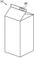
- FIG. 1 is a conceptual perspective view of an example of a liquid container with a printed area.
- the ultraviolet laser printing medium (hereinafter also simply referred to as "printing medium") of the present invention has a printing layer containing titanium oxide and a protective resin layer in this order on a base material, and the printing layer
- the content of the titanium oxide in the printing layer is 0.1 g/m 2 or more and 4.0 g/m 2 or less, and the crystallite size of the titanium oxide in the printing layer is 13 nm or more and 53 nm or less.
- An ultraviolet laser printing medium is provided. Although the detailed reason for the above-mentioned effects is unknown, some of them are thought to be as follows.
- the titanium oxide in the printing layer changes color by laser irradiation with an ultraviolet laser, making it possible to print.
- the discoloration of the titanium oxide is caused by the ionic valence of the titanium oxide contained in the printing layer changing from 4 to 3 and oxygen defects occurring, which causes the color to change from white to black, making it visible. It is thought that It is thought that It is thought that the ionic valence of titanium oxide changes when irradiated with light energy corresponding to the band gap of titanium oxide.
- the band gap of titanium oxide varies depending on the crystal system, but is generally about 3.0 to 3.2 eV, and the corresponding wavelength of light is 420 nm or less. Therefore, even if laser light with a wavelength exceeding 420 nm (for example, 532 nm, 1064 nm, 10600 nm) is used, it is difficult to perform printing due to the change in ion valence of titanium oxide as in the present invention. At this time, by setting the content of titanium oxide in the printing layer to 0.1 g/m 2 or more, a printed matter having spots with excellent visibility and excellent print clarity can be obtained.
- Printed matter can be obtained by discoloring titanium oxide by irradiation with ultraviolet laser, but when titanium oxide is reduced during discoloration, oxygen and moisture in the print medium including the print layer are vaporized. Water vapor is generated.
- the present inventors have discovered that a phenomenon occurs in which the protective resin layer in the ultraviolet laser irradiated area swells due to the generated oxygen and water vapor.
- the present invention by setting the content of titanium oxide in the printing layer to 4.0 g/m 2 or less, the generated oxygen and water vapor are not excessive, and the phenomenon of swelling of printed matter and unevenness is suppressed.
- the printable area means an area (portion) where titanium oxide in the area irradiated with the ultraviolet laser changes color from white to black, making it possible to print by irradiating the ultraviolet laser.
- the printing area refers to a portion of the printable area where the titanium oxide actually changes color due to irradiation with the ultraviolet laser and becomes visible, that is, the portion irradiated with the ultraviolet laser.
- the non-printing area means an area (portion) within the printable area that is not irradiated with the ultraviolet laser.
- the ultraviolet laser printing medium has a printable region containing titanium oxide.
- the printing medium has a printing layer containing titanium oxide and a protective resin layer in this order on a base material.
- the printing layer and the protective resin layer may be formed on at least one side of the base material, and may be formed on both sides, but it is preferable that the printing medium has the printing layer and the protective resin layer on only one side in this order. It is preferable.
- the printing layer and the protective resin layer may be provided in this order over the entire surface of the printing medium, but the printing layer and the protective resin layer may be provided in this order only in some areas (parts) where printing is desired. may have.
- the base material may have an additional layer on the opposite side to the surface on which the printed layer and the protective resin layer are provided, for example, an adhesive layer, a vapor deposition layer, a resin layer, etc. may have.
- the number of these layers may be one, or a plurality of layers may be provided.
- the printing medium has a printing layer containing titanium oxide and a protective resin layer in this order on one side of the base material, and a sealant layer (heat sealing layer) on the other side. Good too.
- the sealant layer may be formed on the entire surface of the base material, but the sealant layer may be provided only on some regions (parts) where heat sealability is required.
- the sealant layer is preferably provided on the outermost layer on the opposite side to the side on which the printed layer is formed.
- the printing medium of this embodiment may further have a barrier layer, and when it has a sealant layer, it is preferable to have a barrier layer between the base material and the sealant layer from the viewpoint of oxygen barrier properties. is preferred. Further, it may be provided on the surface on which the printed layer is provided, and when the barrier layer is provided on the surface on which the printed layer is provided, it is preferable to have a barrier layer between the base material and the printed layer. Further, an adhesive layer may be provided between the base material and the printed layer, between the printed layer and the protective resin layer, between the base material and the barrier layer, between the base material and the sealant layer, and between the sealant layer and the barrier layer.
- the ultraviolet laser printing medium of this embodiment has a printing layer containing titanium oxide on a base material.
- the printing layer may be provided by coating or laminating, and is not particularly limited. That is, the printing layer is preferably a coating layer containing titanium oxide or a laminate layer containing titanium oxide.
- the printed layer is more preferably provided by coating, from the viewpoint of ease of providing the printed layer only at desired locations and from the viewpoint of ease of manufacture.
- the above-mentioned "provided by coating” means forming a printed layer using a coating liquid (ink composition), and includes, for example, forming by gravure printing, inkjet printing, etc.
- the printed layer contains titanium oxide, and the content of titanium oxide in the printed layer is 0.1 g/m 2 or more and 4.0 g/m 2 or less.
- the content of titanium oxide in the printing layer is 0.1 g/m 2 or more, preferably 0.2 g/m 2 or more, more preferably 0.3 g/m 2 or more, from the viewpoint of obtaining sufficient printing density. More preferably, it is 0.4 g/m 2 or more, and from the viewpoint of obtaining printing spots with excellent printing clarity for each point, the printing density reaches a plateau, and the cost increase due to containing more than the necessary amount of titanium oxide is suppressed.
- the protective resin layer due to ultraviolet laser irradiation, it is 4.0 g/m 2 or less, preferably 3.0 g/m 2 or less, more preferably 2.0 g/m 2 or less, more preferably 1.5 g/m 2 or less, even more preferably 1.0 g/m 2 or less. If the content of titanium oxide in the printing layer is too large, a large amount of oxygen is generated due to reduction of titanium oxide, which tends to make it difficult to suppress swelling of the protective resin layer. Note that it is sufficient that at least the printable area of the medium for ultraviolet laser printing contains titanium oxide in the above content, and there may be a portion where no printing layer is provided in the area where printing is not performed.
- a region provided with a printed layer having a titanium oxide content of less than 0.1 g/m 2 or more than 4.0 g/m 2 there may be a region provided with a printed layer having a titanium oxide content of less than 0.1 g/m 2 or more than 4.0 g/m 2 . From the viewpoint of manufacturing simplicity, it is also preferable that a printing layer having a titanium oxide content of 0.1 g/m 2 or more and 4.0 g/m 2 or less is provided in the entire area of the printing medium.
- the printing medium may include an undercoat layer that does not contain titanium oxide as a lower layer of the printing layer containing titanium oxide, or a titanium oxide content of less than 0.1 g/m 2 or 4.0 g/m 2 . It may have an undercoat layer exceeding . In such a case, the content of titanium oxide in all layers of the printing layer including the lower layer is 0.1 g/m 2 or more and 4.0 g/m 2 or less.
- the mass (basis weight, solid content) per 1 m 2 of the printing layer is preferably 0.2 g/m 2 or more, more preferably 0.5 g/m 2 from the viewpoint of print density and print clarity for each point. 2 or more, more preferably 1.0 g/m 2 or more, and preferably 50 g/m 2 or less, more preferably 20 g/m 2 or less, even more preferably 10 g/m 2 or less, even more preferably .
- the content of titanium oxide in the printing layer is preferably 0.3% by mass or more, more preferably 1.0% by mass or more, and more preferably 0.3% by mass or more, from the viewpoint of print density and print clarity for each point. Preferably it is 2.0% by mass or more, even more preferably 5.0% by mass or more, particularly preferably 10.0% by mass or more, and the printing density reaches a plateau, which is caused by containing more titanium oxide than necessary.
- the thickness of the printing layer is preferably 0.3 ⁇ m or more, more preferably 1.0 ⁇ m or more, and even more preferably 2.0 ⁇ m or more, from the viewpoint of print clarity for each point and ease of forming the print layer. , and from the viewpoint of the printing density reaching a plateau and the ease of forming a printed layer, preferably 40.0 ⁇ m or less, more preferably 30.0 ⁇ m or less, still more preferably 25.0 ⁇ m or less, even more preferably 20.0 ⁇ m. It is as follows. The thickness of the printing layer is measured from an electron microscope (SEM) observation image of a cross section of the printing medium.
- SEM electron microscope
- the base material of the printing medium is preferably a paper base material or a film base material, and the paper base material or film base material itself may contain titanium oxide.
- the printing layer preferably contains a thermoplastic resin in addition to titanium oxide. Furthermore, it may contain inorganic pigments other than titanium oxide. Each component will be explained in detail below.
- Titanium oxide contained in the printing layer is represented by the composition formula TiO 2 and is also called titanium dioxide or titania.
- the crystallite size of titanium oxide in the printing layer is 13 nm or more. If the crystallite size of titanium oxide in the printing layer is less than 13 nm, there will be many crystal defects, and recombination of excited electrons and holes excited by ultraviolet laser irradiation will easily occur, and as a result, titanium oxide will be difficult to reduce. , the print clarity for each point is poor.
- the crystallite size of titanium oxide is preferably 20 nm or more, more preferably 30 nm or more, still more preferably 35 nm or more, even more preferably 40 nm or more.
- the crystallite size of titanium oxide is 53 nm or less, preferably 50 nm or less, from the viewpoint of suppressing the swelling of the protective resin layer due to ultraviolet laser irradiation and from the viewpoint of dispersion stability in the coating liquid and printing layer. It is. It is preferable that the upper limit of the crystallite size of titanium oxide is within the above range, since the generation of oxygen and the like during ultraviolet laser irradiation will not be excessive, and swelling of the protective resin layer will be suppressed.
- titanium oxide has good dispersion stability in the coating liquid and the printing layer, and is preferable because it has excellent printing uniformity.
- the crystallite size of titanium oxide is measured by the method described in Examples. The crystallite size is determined by the Scherrer equation, and the Bragg angle is the measured value of the maximum strength derived from the 101 plane for anatase titanium oxide and the 110 plane for rutile titanium oxide. use.
- any of the titanium oxides may have a crystalline structure, and is preferably at least one selected from rutile-type titanium oxide, anatase-type titanium oxide, and brookite-type titanium oxide. It is more preferably at least one selected from type titanium oxide and anatase type titanium oxide, and even more preferably rutile type titanium oxide.
- the crystal form of titanium oxide can be determined by a known method, and specifically, by Raman spectrum, XRD pattern analysis, etc. For example, when identifying from a Raman spectrum, peaks are generally confirmed at 447 ⁇ 10cm -1 and 609 ⁇ 10cm -1 for the rutile type, and peaks at 395 ⁇ 10cm -1 and 516 ⁇ 10cm for the anatase type. -1 , a peak is confirmed at 637 ⁇ 10 cm -1 .
- One type of titanium oxide may be used alone, or two or more types may be used in combination.
- the diffraction angle of the titanium oxide is preferably 27.60° or less from the viewpoint of print clarity for each point.
- the Bragg angle of rutile-type titanium oxide is originally 27.40°, but if the crystallinity is low, the diffraction angle tends to become high.
- the diffraction angle of titanium oxide exceeds 27.60°, crystallinity is low and discoloration is suppressed, so that print clarity for each point tends to be poor.
- the diffraction angle of the titanium oxide is preferably 27.60° or less, more preferably 27.55° or less, and still more preferably 27.50° or less.
- the diffraction angle of titanium oxide is the actual value of the maximum intensity derived from the 110 plane, as described above.
- the shape of titanium oxide is not particularly limited, and may be any shape such as amorphous, spherical, rod-like, or needle-like.
- the average particle diameter of the titanium oxide is not particularly limited, but from the viewpoint of obtaining a printing medium with excellent surface smoothness, it is preferably 0.01 ⁇ m or more, more preferably 0.05 ⁇ m or more. , more preferably 0.10 ⁇ m or more, even more preferably more than 0.15 ⁇ m, particularly preferably 0.16 ⁇ m or more, and preferably 20.0 ⁇ m or less, more preferably 5.0 ⁇ m or less, still more preferably 1. It is 0 ⁇ m or less, even more preferably 0.50 ⁇ m or less, particularly preferably 0.30 ⁇ m or less.
- the major axis of the titanium oxide is not particularly limited, but from the viewpoint of obtaining a printing medium with excellent surface smoothness, it is preferably 0.1 ⁇ m or more, more preferably 0.5 ⁇ m or more, More preferably, it is 1.5 ⁇ m or more, and preferably 50.0 ⁇ m or less, more preferably 30.0 ⁇ m or less, and still more preferably 15.0 ⁇ m or less.
- the short axis is preferably 0.01 ⁇ m or more, more preferably 0.03 ⁇ m or more, even more preferably 0.05 ⁇ m or more, and preferably 3.0 ⁇ m or less, more preferably 1.5 ⁇ m or less, and even more preferably is 1.0 ⁇ m or less.
- the aspect ratio (longer axis/breadth axis) is preferably 5 or more, more preferably 10 or more, even more preferably 15 or more, and preferably 300 or less, more preferably It is 100 or less, more preferably 30 or less.
- the particle diameter, major axis, and minor axis of titanium oxide are measured by the method described in Examples. Note that the values of the particle diameter, major axis, and minor axis of titanium oxide used as a raw material may be adopted, or the catalog values of the particle diameter, major axis, and minor axis of titanium oxide used as a raw material may be adopted. .
- thermoplastic resin used in the printing layer functions as a binder.
- the thermoplastic resin for the printing layer is not particularly limited, but when the printing layer is provided by coating, it may be applied as an aqueous coating solution or an organic solvent-based coating solution (oil-based coating solution). .
- the printing layer when a printing layer is provided by coating, the printing layer is also referred to as a coating layer.
- the composition used to provide the coating layer is also referred to as a coating liquid or an ink composition.
- the thermoplastic resin is preferably a water-dilutable thermoplastic resin. Examples of water-dilutable resins include water-soluble, emulsion-type, and dispersion-type resins.
- Water-dilutable thermoplastic resins may be either natural resins or synthetic resins, such as starch derivatives, casein, shellac, polyvinyl alcohol and its derivatives, acrylic resins, maleic acid resins, urethane resins, and polyester resins. Examples include resins, styrene-butadiene resins, vinyl chloride resins, and polyolefin resins. More specifically, acrylic resins include acrylic resins copolymerized with (meth)acrylic acid and its alkyl ester or styrene as monomer components, styrene-maleic acid resins, and styrene-acrylic acid-maleic acid resins.
- Examples include resin, water-soluble polyurethane resin, and water-soluble polyester resin.
- resin water-soluble polyurethane resin
- water-soluble polyester resin examples include starch derivatives, casein, shellac, polyvinyl alcohol and its derivatives, acrylic resins, maleic acid resins, and styrene-butadiene resins.
- At least one selected from starch derivatives, polyvinyl alcohol, polyvinyl alcohol derivatives, acrylic resins, maleic acid resins, and styrene-butadiene resins is more preferable, and starch derivatives, polyvinyl alcohol, polyvinyl At least one selected from alcohol derivatives, acrylic resins, and styrene-butadiene resins is more preferred, and at least one selected from polyvinyl alcohol, polyvinyl alcohol derivatives, acrylic resins, and styrene-butadiene resins is even more preferred. .
- These resins may be used alone or in combination of two or more.
- thermoplastic resins When using an organic solvent-based coating liquid (oil-based coating liquid), cellulose resins (e.g., nitrified cotton, cellulose acetate, cellulose acetate propionate, etc.), polyurethane resins, acrylic resins, vinyl chloride, etc. It is preferable to use known thermoplastic resins such as polymeric resins.
- the content of the thermoplastic resin is not particularly limited, and may be appropriately selected depending on the type of thermoplastic resin, the content of titanium oxide in the coating liquid, the inorganic pigment described below, etc. Of the solid content, it is preferably 5% by mass or more, more preferably 10% by mass or more, even more preferably 15% by mass or more, and preferably 99% by mass or less, more preferably 90% by mass or less.
- the coating layer is preferably provided by applying and drying a coating liquid.
- the aqueous medium used includes water or a mixture of water and a water-miscible solvent.
- Water-miscible solvents include lower alcohols, polyhydric alcohols, and alkyl ethers or alkyl esters thereof. Specifically, lower alcohols such as methyl alcohol, ethyl alcohol, normal propyl alcohol, and isopropyl alcohol, polyhydric alcohols such as ethylene glycol, propylene glycol, diethylene glycol, dipropylene glycol, and glycerin, ethylene glycol monomethyl ether, and ethylene glycol.
- Examples include monoethyl ether, ethylene glycol monoacetate, propylene glycol monomethyl ether, propylene glycol monoethyl ether, propylene glycol monoacetate, diethylene glycol monomethyl ether, and dipropylene glycol monomethyl ether.
- organic solvent-based coating liquids aromatic organic solvents such as toluene and xylene, ethyl acetate, n-propyl acetate, isobutyl acetate, ester organic solvents, methyl ethyl ketone, methyl isobutyl ketone
- solvents such as ketone organic solvents such as, alcohol organic solvents such as methanol, ethanol, isopropanol, and n-butanol, and hydrocarbon solvents such as methylcyclohexane.
- the solid content concentration of the coating liquid is not particularly limited, but is preferably 10 mass from the viewpoint of obtaining a desired coating layer thickness, the viscosity of the coating liquid for easy coating, and the ease of drying. % or more, more preferably 20% by mass or more, still more preferably 30% by mass or more, and preferably 80% by mass or less, more preferably 75% by mass or less, still more preferably 70% by mass or less, even more preferably It is 65% by mass or less.
- the viscosity of the coating liquid is preferably 10 mPa ⁇ s (20°C) or more, as measured by a Brookfield viscometer, from the viewpoints of coating suitability, obtaining the desired thickness of the coating layer, and ease of drying. More preferably 15 mPa ⁇ s (20°C) or more, still more preferably 20 mPa ⁇ s (20°C) or more, and preferably 5000 mPa ⁇ s (20°C) or less, more preferably 4000 mPa ⁇ s (20°C) or less , more preferably 3000 mPa ⁇ s (20°C) or less, even more preferably 2000 mPa ⁇ s (20°C) or less.
- the printed layer When the printed layer is provided by lamination, it is preferable to laminate a film containing titanium oxide on the base material. Note that when the printed layer is provided by lamination, the printed layer is also referred to as a laminate layer.
- the thermoplastic resin constituting the laminate layer is not particularly limited, as long as it can be processed into a film by incorporating titanium oxide, and may be appropriately selected from known thermoplastic resins.
- polyester resins such as polyethylene terephthalate, polybutylene terephthalate, and polyethylene naphthalate, polyvinyl chloride, polyvinylidene chloride, polybutene, polybutadiene, ethylene-vinyl acetate copolymer, polyethylene, polypropylene, and ethylene-propylene copolymer.
- polyolefin resins such as polycarbonate, polymethylpentene, polycarbonate, polyurethane, polyamide, polyacrylonitrile, and poly(meth)acrylate.
- the resins constituting the laminate layer are polyethylene, polypropylene, and ethylene because they can be used for general purposes, have high ultraviolet transmittance, and can discolor titanium oxide to the inside of the film.
- the resins constituting the laminate layer are polyethylene, polypropylene, and ethylene because they can be used for general purposes, have high ultraviolet transmittance, and can discolor titanium oxide to the inside of the film.
- - Preferably contains polyolefins such as propylene copolymers, polyesters such as polyethylene terephthalate, polybutylene terephthalate, polylactic acid, polybutylene succinate, etc., including polyethylene, polypropylene, ethylene-propylene copolymers, polyethylene terephthalate, polylactic acid, and polybutylene succinate, and more preferably contains at least one selected from the group consisting of polyethylene, polypropylene, ethylene-propylene copolymer, polyethylene terephthalate, polylactic acid, and polybutylene succinate.
- the resin constituting the laminate layer is even more preferably polyolefin, and even more preferably at least one selected from the group consisting of polyethylene and polypropylene.
- Polyethylene (PE) is broadly classified into linear low density polyethylene (LLDPE), low density polyethylene (LDPE), medium density polyethylene (MDPE), and high density polyethylene (HDPE). Among these, low density polyethylene (LDPE) is preferred because it has excellent extrusion lamination properties.
- polyester which is a biodegradable resin, as the resin constituting the laminate layer, since the environmental load is reduced, and examples thereof include polylactic acid and polybutylene succinate. These resins may be used alone or in combination of two or more.
- the content of the thermoplastic resin in the laminate layer is preferably 20% by mass or more, more preferably 30% by mass or more, and even more preferably is 50% by mass or more, even more preferably 70% by mass or more, particularly preferably 80% by mass or more, and preferably 99% by mass or less, more preferably 98% by mass or less, even more preferably 95% by mass or less. be.
- the printing layer may contain other components in addition to the titanium oxide and thermoplastic resin described above.
- Other components include inorganic pigments other than titanium oxide (hereinafter also simply referred to as "inorganic pigments"). Containing an inorganic pigment other than titanium oxide is preferable because it suppresses heat generation of titanium oxide and softening of the protective resin layer due to ultraviolet laser irradiation, and as a result, suppresses the occurrence of swelling of the protective resin layer.
- examples of inorganic pigments include calcium carbonate, talc, silica, kaolin, magnesium oxide, mica, aluminum hydroxide, and barium sulfate.
- calcium carbonate, talc, silica, kaolin, magnesium oxide, zinc oxide, and mica It is preferably at least one selected from the group consisting of calcium carbonate and talc, and more preferably at least one selected from the group consisting of calcium carbonate and talc.
- Inorganic pigments may be used alone or in combination of two or more.
- the shape of the inorganic pigment is not particularly limited, and may be any shape such as amorphous, spherical, plate-like, rod-like, or needle-like.
- the average particle diameter of the inorganic pigment is not particularly limited, but from the viewpoint of obtaining a printing medium with excellent surface smoothness and suppressing the occurrence of swelling of the protective resin layer. From this point of view, it is preferably 0.1 ⁇ m or more, more preferably 0.15 ⁇ m or more, even more preferably 0.20 ⁇ m or more, and preferably 10 ⁇ m or less, more preferably 5 ⁇ m or less, and still more preferably 3 ⁇ m or less.
- the major axis of the inorganic pigment is not particularly limited, but from the viewpoint of obtaining a printing medium with excellent surface smoothness and from the viewpoint of suppressing swelling of the protective resin layer, it is preferably 0. It is 5 ⁇ m or more, more preferably 1.0 ⁇ m or more, even more preferably 2.0 ⁇ m or more, and preferably 100 ⁇ m or less, more preferably 10 ⁇ m or less, and even more preferably 5 ⁇ m or less.
- the short axis is preferably 0.1 ⁇ m or more, more preferably 0.5 ⁇ m or more, even more preferably 1.0 ⁇ m or more, and preferably 50 ⁇ m or less, more preferably 10 ⁇ m or less, and even more preferably 1.0 ⁇ m. It is as follows. Further, when the inorganic particles are acicular, the aspect ratio (major axis/breadth axis) is preferably 1.5 or more, more preferably 2.0 or more, still more preferably 3.0 or more, and preferably It is 100 or less, more preferably 50 or less, even more preferably 30 or less.
- the content of the inorganic pigment in the printing layer is preferably 2% by mass or more, more preferably 10% by mass, from the viewpoint of suppressing the occurrence of swelling of the protective resin layer. % or more, more preferably 20% by mass or more, even more preferably 30% by mass or more, particularly preferably 50% by mass or more, and preferably 95% by mass or less, more preferably 90% by mass or less, even more preferably It is 85% by mass or less, more preferably 80% by mass or less.
- the mass ratio of titanium oxide to the inorganic pigment other than titanium oxide suppresses the occurrence of swelling of the protective resin layer. From the viewpoint of .2 or less.
- the printing layer contains a film forming agent, a pigment dispersant, a pigment dispersion resin, an antiblocking agent, a wetting agent, a viscosity modifier, a pH modifier, an antifoaming agent, a general surfactant, etc. You can leave it there.
- the coating liquid is an aqueous coating liquid
- the coating liquid is an aqueous coating liquid
- titanium oxide, a thermoplastic resin, water, and if necessary, an inorganic pigment other than titanium oxide, a water-miscible solvent, and a pigment dispersion are added before mixing with the aqueous medium.
- a pigment-dispersing agent, a pigment-dispersing resin, etc. may be mixed and kneaded, and then water, a water-miscible solvent if necessary, and the rest of the predetermined materials may be further added and mixed.
- the coating liquid is an oil-based coating liquid
- titanium oxide or a pigment other than titanium oxide may be added after mixing the organic solvent and the resin. may be added to the mixed solution of the organic material and resin, or may be added later.
- the coating liquid is obtained by mixing and dispersing the above-mentioned components using a high-speed stirrer such as a homo mixer or a lab mixer, or a disperser such as a Coles disperser, a three-roll mill, or a bead mill.
- the coating method for applying the coating liquid is not particularly limited, and includes flexo printing, inkjet printing, gravure printing, screen printing, pad printing, spray coating, Meyer bar, gravure coater, air knife coater, blade coater, rod coater, die coater, and bar. What is necessary is just to apply
- the film to be laminated is prepared by preparing a raw material composition by melting and kneading at least titanium oxide, a thermoplastic resin, and, if necessary, materials such as an inorganic pigment, and molding this into a film. After that, it can be obtained by stretching as necessary.
- a masterbatch containing titanium oxide or inorganic pigment at a high concentration may be prepared and then mixed with the resin.
- the materials may be uniformly mixed in advance and charged into the molding machine, or may be mixed in a hopper or kneader integrated with the molding machine.
- the method for forming the film into a film may be appropriately selected from conventionally known methods, such as melt extrusion, melt casting, and calendering.
- the base material and the film may be attached via an adhesive layer, or preferably laminated.
- the adhesive layer is not particularly limited, and may be appropriately selected from known adhesive layers.
- the adhesive layer disclosed in JP-A No. 2012-57112 is exemplified.
- Specific examples of lamination include laminating a base material and a laminate layer by a thermal lamination method, a dry lamination method, a wet lamination method, an extrusion lamination method, or the like.
- the extrusion lamination method is preferable from the viewpoint of the manufacturing process since it does not require the step of pasting the laminate layer and the base material.
- the base material is not particularly limited as long as it is possible to provide a printed layer, and may be appropriately selected from various base materials such as paper, nonwoven fabric, cloth, film (resin film), metal, etc. Bye. Among these, from the viewpoint of easy formation of a printed layer, at least one selected from paper, nonwoven fabric, cloth, and film is more preferable, and at least one selected from paper and film is more preferable. is even more preferable.
- the base material is paper
- the base material is also referred to as a paper base material.
- a base material is a resin film
- the said base material is also called a film base material.
- the paper base material may be coated paper in which a coating layer is provided on paper, and the coating layer may be provided on the printing layer side of the paper base material, and the coating layer may be provided on the printing layer side of the paper base material, and the coating layer may be provided on the printing layer side of the paper base material, and the coating layer may be provided on the printing layer side of the paper base material. It may be provided in, and is not particularly limited.
- a paper base material may be used as the base material.
- the raw material pulp constituting the paper base material include wood pulp, non-wood pulp, and deinked pulp.
- Wood pulp is not particularly limited, but includes, for example, hardwood bleached kraft pulp (LBKP), hardwood unbleached kraft pulp (LUKP), softwood bleached kraft pulp (NBKP), softwood unbleached kraft pulp (NUKP), and sulfite pulp ( Chemical pulp such as SP), dissolving pulp (DP), soda pulp (AP), oxygen bleached kraft pulp (OKP), semi-chemical pulp such as semi-chemical pulp (SCP), chemical ground wood pulp (CGP), ground wood pulp ( Examples include mechanical pulps such as GP), thermomechanical pulp (TMP), and chemithermomechanical pulp (CTMP).
- LLKP hardwood bleached kraft pulp
- LKP hardwood unbleached kraft pulp
- NKP softwood bleached kraft pulp
- NUKP softwood unbleached kraft pulp
- non-wood pulp examples include, but are not particularly limited to, cotton-based pulps such as cotton linters and cotton lint, and non-wood-based pulps such as hemp, wheat straw, bamboo, and bagasse.
- Deinked pulp is not particularly limited, but includes, for example, deinked pulp made from waste paper.
- the raw material pulp may be used alone or in combination of two or more of the above.
- the raw material pulp may be mixed with organic synthetic fibers such as polyamide fibers and polyester fibers, recycled fibers such as polynosic fibers, and inorganic fibers such as glass fibers, ceramic fibers, and carbon fibers. From the viewpoint of easy availability, the raw material pulp is preferably wood pulp or deinked pulp.
- the raw material pulp is preferably a chemical pulp, more preferably a kraft pulp, and even more preferably a kraft pulp from a hardwood such as eucalyptus or acacia, or a pine or cedar pulp. It is one or more types selected from softwood kraft pulp such as, etc., more preferably one or more types selected from hardwood bleached kraft pulp (LBKP) and softwood bleached kraft pulp (NBKP), and particularly preferably LBKP. .
- the length-weighted average fiber length of the pulp constituting the paper base material is preferably 0.6 mm or more, more preferably 0.65 mm or more, from the viewpoint of suppressing coating unevenness and improving the clarity of each printing point. , more preferably 0.7 mm or more, and preferably 3.5 mm or less, more preferably 2.5 mm or less, even more preferably 2.0 mm or less, even more preferably 1.5 mm or less, particularly preferably It is 1.0 mm or less. If the length-weighted average fiber length of the pulp constituting the paper base material is below the above upper limit, the pulps will become tightly entangled with each other, reducing the voids in the paper base material and making it difficult to coat when a coating layer is provided.
- the length-weighted average fiber length of the pulp constituting the paper base material is measured by the method described in the Examples.
- the average fiber width of the pulp fibers constituting the paper base material is preferably 14.0 ⁇ m or more, more preferably 15.0 ⁇ m or more, even more preferably 15.5 ⁇ m or more, even more preferably 16.0 ⁇ m or more, and, It is preferably 35.0 ⁇ m or less, preferably 33.0 ⁇ m or less, more preferably 31.0 ⁇ m or less, even more preferably 28.0 ⁇ m or less, even more preferably 24.0 ⁇ m or less, even more preferably 21.0 ⁇ m or less. be.
- the average fiber width of the pulp fibers constituting the paper base material is 35.0 ⁇ m or less, the pulps become tightly entangled with each other, which smooths the surface of the paper base material and reduces coating unevenness when a printed layer is provided. This is preferable because it suppresses this and smoothes the surface of the printing layer, resulting in printed matter with excellent print clarity on a point-by-point basis. Moreover, it is preferable that the average fiber width is 14.0 ⁇ m or more, since the strength as a paper base material is improved, and paper dust is further reduced, so that falling off of printed areas can be suppressed.
- the average fiber width of the pulp fibers constituting the paper base material can be measured by the method described in Examples.
- the number ratio of fine fibers with a fiber length of 0.2 mm or less is preferably 4% or more, more preferably 5% or more, still more preferably 6% or more, and even more preferably 10%. Above, it is particularly preferably 15% or more, and preferably 40% or less, more preferably 30% or less, and still more preferably 20% or less. It is preferable that the number ratio of fine fibers is 40% or less, since the strength as a paper base material can be ensured, and falling off of printed areas due to detachment of fine fibers can be suppressed.
- the fine fibers are arranged to fill the gaps between the fibers, reducing the voids in the paper base material and preventing uneven coating when a coating layer is provided. This is preferable because the print clarity and print uniformity for each point are improved as a result.
- the number ratio of fine fibers with a fiber length of 0.2 mm or less in the pulp constituting the paper base material is determined by disintegrating the paper base material by the method described in the example, and calculating the fiber length of the resulting pulp slurry. Calculated by measuring with a measuring device (for example, manufactured by Valmet, model FS-5, with UHD base unit). Fibers with a fiber length of 0.2 mm or less and a fiber width of 75 ⁇ m or less are defined as fine fibers, and the ratio of the number of fine fibers to the number of measured pulps is calculated.
- the water retention degree of the pulp fibers constituting the paper base material is preferably 140% or less, more preferably 130% or less, and even more preferably 125% or less, from the viewpoint of suppressing the occurrence of swelling of the protective resin layer due to ultraviolet laser printing.
- the lower limit is not particularly limited, it is preferably 95% or more, more preferably 100% or more, even more preferably 105% or more, even more preferably 110% or more, even more preferably 115% or more.
- the titanium oxide that absorbs the ultraviolet laser light generates heat, which also heats the pulp that makes up the paper base material located directly below, thereby generating water vapor.
- the water retention of pulp fibers tends to be high when the hemicellulose content in the pulp fibers is high. Therefore, when a dissolving pulp with a high ⁇ -cellulose content and a reduced hemicellulose content is used as a raw material pulp, the water retention tends to decrease. Moreover, when the degree of beating of pulp fibers is high, the water retention tends to improve. Therefore, when pulp fibers with a small Canadian Standard Freeness (CSF) and a high degree of beating are used, the water retention tends to increase.
- the water retention degree of the pulp fibers constituting the paper base material is measured by the method described in the Examples.
- the Canadian Standard Freeness (CSF) of the wood pulp used for the paper base material is preferably 150 mL or more, more preferably It is 300 mL or more, more preferably 400 mL or more, and preferably 800 mL or less, more preferably 750 mL or less, still more preferably 700 mL or less, even more preferably 600 mL or less.
- CSF is Canadian Standard Freeness according to JIS P 8121-2:2012.
- the paper base material is obtained by paper-making a pulp slurry to which internal additives are added as necessary.
- the paper base material includes fillers, sizing agents, dry paper strength agents, wet paper strength agents (e.g., polyamide polyamine epichlorohydrin), retention aids (e.g., sulfate), Known internal additives for papermaking such as drainage improvers, pH adjusters, softeners, antistatic agents, antifoaming agents, dyes and pigments can be added as necessary.
- fillers include kaolin, talc, titanium oxide, heavy calcium carbonate, light calcium carbonate, calcium sulfite, gypsum, calcined kaolin, white carbon, amorphous silica, delaminated kaolin, diatomaceous earth, magnesium carbonate, and hydroxide.
- examples include aluminum, calcium hydroxide, magnesium hydroxide, and zinc hydroxide.
- the sizing agent include rosin-based, alkyl ketene dimer-based, alkenyl succinic anhydride-based, styrene-acrylic-based, higher fatty acid-based, and petroleum resin-based sizing agents.
- a known wet paper machine such as a fourdrinier paper machine, a gap former paper machine, a cylinder paper machine, a short wire paper machine, etc. is appropriately selected and used. be able to.
- the paper layer formed by the paper machine is conveyed using felt and dried using a dryer.
- a multi-stage cylinder dryer may be used as a pre-dryer before drying.
- the paper base material obtained as described above may be subjected to surface treatment using a calendar to make the thickness and profile uniform, thereby improving printability.
- a known calendering machine can be appropriately selected and used.
- the paper base material may be appropriately selected from conventionally known paper base materials such as liner base paper, kraft paper, high-quality paper, and coated paper. Further, the paper base material may be a single layer or a multilayer, and may have a multilayer structure with different pulp compositions.
- the basis weight of the paper base material is preferably 30 g/m 2 or more, more preferably 35 g/m 2 or more, and preferably 1000 g/m 2 or less, from the viewpoint of strength as a printing paper and improvement of printability. , more preferably 700 g/m 2 or less.
- the basis weight is measured by the method specified in JIS P 8124:2011.
- the thickness of the paper base material is not particularly limited, but from the viewpoint of strength as printing paper and improvement of printability, it is preferably 30 ⁇ m or more, more preferably 35 ⁇ m or more, still more preferably 40 ⁇ m or more, even more preferably 50 ⁇ m or more. It is preferably 900 ⁇ m or less, more preferably 500 ⁇ m or less, and even more preferably 300 ⁇ m or less.
- the thickness of the paper base material can be measured by the method described in JIS P 8118:2014.
- the density of the paper base material is not particularly limited, but from the viewpoint of strength as a printing paper and improvement of printability, it is preferably 0.6 g/cm 3 or more, more preferably 0.7 g/cm 3 or more, and, Preferably it is 1.2 g/cm 3 or less, more preferably 1.0 g/cm 3 or less, even more preferably 0.9 g/cm 3 or less.
- the density of the paper base material is calculated from the basis weight and thickness of the paper base material described above.
- the resin constituting the film base material (hereinafter also simply referred to as "resin") is not particularly limited, as long as it can be processed into a film, and may be appropriately selected from known thermoplastic resins. Specifically, polyester resins such as polyethylene terephthalate, polybutylene terephthalate, polyethylene naphthalate, polylactic acid, polybutylene succinate, polyvinyl chloride, polyvinylidene chloride, polybutene, polybutadiene, ethylene-vinyl acetate copolymer , polyolefin resins such as polyethylene, polypropylene, ethylene-propylene copolymer, and polymethylpentene; polycarbonate; polyurethane; polyamide; polyacrylonitrile; and poly(meth)acrylate.
- polyester resins such as polyethylene terephthalate, polybutylene terephthalate, polyethylene naphthalate, polylactic acid, polybutylene succinate, polyvinyl chloride, polyvin
- resins constituting the film base material include polyolefins such as polyethylene, polypropylene, ethylene-propylene copolymer, polyethylene terephthalate, polybutylene terephthalate, polylactic acid, and polybutylene, from the viewpoint of general-purpose use. It preferably contains polyester such as succinate, polyvinyl chloride, and at least one selected from the group consisting of polyethylene, polypropylene, ethylene-propylene copolymer, polyethylene terephthalate, polylactic acid, and polybutylene succinate.
- the film base material contains at least one selected from the group consisting of polyethylene, polypropylene, ethylene-propylene copolymer, polyethylene terephthalate, polylactic acid, and polybutylene succinate.
- the resin constituting the film base material is even more preferably a polyolefin, even more preferably at least one selected from the group consisting of polyethylene and polypropylene, and particularly preferably contains at least polypropylene.
- polyester which is a biodegradable resin, as the resin constituting the film base material, since the environmental load is reduced, and examples thereof include polylactic acid and polybutylene succinate. These resins may be used alone or in combination of two or more.
- the film base material may be stretched or unstretched, and is not particularly limited.
- the film base material when it is a polypropylene film, it may be an unstretched polypropylene film (CPP) or a biaxially oriented polypropylene film (OPP).
- CPP unstretched polypropylene film
- OPP biaxially oriented polypropylene film
- other components may be added to the film base material within a range that does not impair the effects of the present invention, such as pigments containing titanium oxide, antistatic agents, etc. , antiblocking agents, antioxidants, ultraviolet absorbers, HALS, plasticizers, lubricants, flame retardants, mold release agents, colorants and the like.
- the thickness of the film base material is preferably 10 ⁇ m or more, more preferably 15 ⁇ m or more, even more preferably 20 ⁇ m or more, and preferably 500 ⁇ m or less, more preferably 300 ⁇ m or less, and even more preferably It is 100 ⁇ m or less.
- the thickness of the film is measured by the method described in the Examples.
- the film base material may be prepared by preparing a raw material composition by melting and kneading materials such as a resin and, if necessary, an inorganic pigment, forming this into a film shape, and then stretching the composition as appropriate.
- a raw material composition if it contains an inorganic pigment containing titanium oxide for the film base material, it is possible to prepare a masterbatch containing a high concentration of the inorganic pigment and then mix this with the resin. good.
- the materials may be uniformly mixed in advance and charged into the molding machine, or may be mixed in a hopper or kneader integrated with the molding machine.
- the method for forming the film into a film may be appropriately selected from conventionally known methods, such as melt extrusion, melt casting, calendering, and the like.
- the stretching treatment may be uniaxial stretching or biaxial stretching.
- stretching process it is preferable to stretch at least in the longitudinal direction, and in addition, stretching may be carried out in the transverse direction.
- the raw materials constituting the cloth and nonwoven fabric include natural fibers such as cotton, linen, cellulose fiber, wool, etc.; synthetic fibers such as polycarbonate, polyetherimide, polyester, polyurethane, and polyamide ( Examples include recycled fibers such as rayon and acetate.
- any commercially available base material may be used as appropriate.
- various commercially available papers may be used as the paper base material, and resin films of various resins may be used as the film base material. may be adopted.
- the printing medium of this embodiment has the following advantages: from the viewpoint of improving the water resistance of the printing medium, from the viewpoint of functioning as a protective layer, from the viewpoint of high print density and improving the print clarity of each point, and from the viewpoint of ultraviolet laser printing.
- a protective resin layer is further provided on the printed layer.
- the total light transmittance of the protective resin layer is preferably 40% or more, more preferably 60% or more, even more preferably 70% or more, even more preferably 80% or more, particularly preferably 90% or more, and, It is 100% or less.
- the upper limit is not particularly limited. Total light transmittance is measured in accordance with JIS K 7361-1:1997.
- the resin constituting the protective resin layer preferably has a total light transmittance of 40% or more, and is not particularly limited as long as it can be provided on a substrate provided with a printed layer. From the viewpoint of transparency and ease of providing a protective resin layer, either the protective resin layer and the base material provided with the printed layer are attached via an adhesive layer, or the protective resin layer provided with the printed layer is attached. It is preferable to attach the protective resin layer and the base material via an adhesive layer, or to laminate the protective resin layer and the base material provided with the printing layer by laminating the protective resin layer and the base material provided with the printing layer.
- examples of the resin constituting the protective resin layer include polyolefins such as polyethylene and polypropylene; polyesters such as polyethylene terephthalate; polyvinyl alcohol; and starch; among these, the group consisting of polyolefins, polyesters, and polyvinyl alcohols; It is preferably at least one selected from polyethylene, polypropylene, polyethylene terephthalate, and polyvinyl alcohol, more preferably polyethylene, polypropylene, and polypropylene. is particularly preferred.
- the protective resin layer may be stretched or unstretched, and is not particularly limited.
- examples include acrylic resin, styrene-maleic acid resin, water-soluble polyurethane resin, and water-soluble polyester resin.
- acrylic resins include resins obtained by copolymerizing (meth)acrylic acid with other monomers such as its alkyl ester, styrene, unsaturated carboxylic acids other than (meth)acrylic acid, ethylene, and propylene. Specific examples include ethylene-(meth)acrylic acid copolymer and styrene-acrylic acid-maleic acid resin, with ethylene-(meth)acrylic acid copolymer being preferred.
- the base material having the protective resin layer and the printed layer may be laminated by any method, and is not particularly limited, but from the viewpoint of ease of manufacture, the protective resin layer and the base material having the printed layer may be laminated using an adhesive.
- a protective resin layer with a printed layer and a substrate may be bonded to each other through an adhesive layer, or a transparent coating may be applied in the form of a liquid coating. It is preferable to paste it.
- the adhesive layer is not particularly limited, and may be appropriately selected from known adhesive layers. Specifically, the adhesive layer disclosed in JP-A No. 2012-57112 is exemplified.
- the thickness of the protective resin layer is not particularly limited, but is preferably 5 ⁇ m from the viewpoint of suppressing swelling of the protective resin layer due to ultraviolet laser irradiation, obtaining clear printing, and handling of printed matter and printing media. Above, it is more preferably 10 ⁇ m or more, still more preferably 12 ⁇ m or more, and preferably 100 ⁇ m or less, more preferably 75 ⁇ m or less, and even more preferably 50 ⁇ m or less. Note that if the protective resin layer is thin, the protective resin layer tends to bulge due to ultraviolet laser irradiation.
- the printing medium of this embodiment may have a sealant layer on the surface of the base material opposite to the surface on which the printing layer is provided.
- the sealant layer is a layer that is melted and bonded by heating, ultrasonic waves, or the like.
- the printing medium of this embodiment may have sealant layers on both sides of the base material.
- it is sufficient that the sealant layer is provided at least on the opposite side of the base material to the side on which the printed layer is provided, but it may also be provided on the side on which the printed layer is provided.
- the resin constituting the sealant layer (hereinafter also referred to as "sealant layer resin”) is not particularly limited, but includes, for example, vinyl chloride resin, vinyl acetate resin, vinyl chloride-vinyl acetate copolymer, acrylic resin, and polyester resin. , olefin resins, styrene resins, styrene acrylic resins (eg, styrene-acrylic acid copolymers), ethylene acrylic resins (ethylene-(meth)acrylic acid copolymers), and modified products thereof.
- the sealant layer resins may be used alone or in combination of two or more.
- the resin for the sealant layer either a synthetic product or a commercially available product may be used, and the commercially available products include those used in the examples.
- the sealant layer may be formed by laminating by melt extrusion, adhesive, etc., and a method of forming the sealant layer by preparing a coating liquid for the sealant layer and applying the coating liquid is exemplified.
- the adhesive a known adhesive can be used. Note that two or more sealant layers may be formed. Note that when the sealant layer is laminated with a sealant layer resin film using an adhesive or the like, the resin film may be unstretched, or may be uniaxially or biaxially stretched.
- the resin for the sealant layer should be selected from the group consisting of polyolefin resins, polyamide resins, polyester resins, and polyvinylidene chloride resins from the viewpoint of heat sealing properties and gas barrier properties. It is more preferable to contain at least one selected kind, it is more preferable to contain a polyolefin resin, and it is even more preferable that it is a polyolefin resin.
- the surface opposite to the base material (outermost layer) is preferably a polyolefin resin layer, and is preferably a polyethylene resin layer. It is more preferable.
- the polyolefin resin is more preferably at least one selected from the group consisting of polyethylene, polypropylene, and ethylene-propylene copolymers, and is at least one of polyethylene and polypropylene. is even more preferable.
- the polyethylene may be low density polyethylene (LDPE), linear low density polyethylene (LLDPE), medium density polyethylene (MDPE), or high density polyethylene (HDPE).
- polyamide resins examples include nylon 6, nylon 11, nylon 12, nylon 66, nylon 610, and nylon 612.
- polyester resin examples include polyethylene terephthalate (PET), polyethylene naphthalate (PEN), polybutylene terephthalate (PBT), and derivatives thereof. Note that many of the biodegradable resins described below also correspond to polyester resins.
- PVDC Polyvinylidene chloride resin
- biodegradable resins examples include polylactic acid (PLA), polybutylene succinate (PBS), polybutylene succinate adipate (PBSA), and 3-hydroxybutanoic acid/3-hydroxyhexanoic acid copolymer (PHBH).
- PLA polylactic acid
- PBS polybutylene succinate
- PHBH 3-hydroxybutanoic acid/3-hydroxyhexanoic acid copolymer
- PLA polylactic acid
- PBS polybutylene succinate
- PBS polybutylene succinate
- PBS polybutylene succinate
- a laminated film in which two or more resins are laminated may be used, such as a polyethylene/polypropylene laminated film, a polyamide resin/polyvinylidene chloride resin laminated film, a polyethylene/polyester resin laminated film, etc. be done.
- the adhesive used is not particularly limited and may be solvent-free, organic solvent-based, water-based, etc., but depending on the shape of the paper base material. From the viewpoint of ensuring stability, it is preferable to use an organic solvent type adhesive or a solventless type adhesive.
- the main components that make up the adhesive include (meth)acrylic acid ester copolymer, ⁇ -olefin copolymer, ethylene-vinyl acetate copolymer, polyvinyl alcohol, polyurethane, styrene-butadiene copolymer, and polyvinyl chloride.
- epoxy resin epoxy resin
- melamine resin silicone resin
- natural rubber casein, starch, etc.
- (meth)acrylic acid ester copolymers ethylene-vinyl acetate copolymers
- polyurethanes polyurethanes
- polyurethanes are more preferred, from the viewpoint of availability and good adhesion.
- commercially available adhesives may be used as appropriate.
- the sealant layer or barrier layer and the base material may be laminated after applying the adhesive to the sealant layer or barrier layer, or the base material and the sealant layer or barrier layer may be laminated after applying the adhesive to the base material. Alternatively, after applying an adhesive to both the sealant layer or barrier layer and the base material, the two may be laminated. Although not particularly limited, from the viewpoint of shape stability, the sealant layer or barrier layer may be laminated. It is preferable to laminate the substrate after applying the adhesive to the substrate.
- the method for applying the adhesive may be appropriately selected from conventionally known methods, and examples thereof include, but are not limited to, a roll coater, a die coater, a gravure coater, a spray coater, and the like.
- the amount of adhesive applied is not particularly limited, but the amount applied after drying (coating amount) is preferably 1 g/m 2 or more, more preferably 1 g/m 2 or more, from the viewpoint of improving the adhesion between the sealant layer or barrier layer and the base material. is 2 g/m 2 or more, more preferably 3 g/m 2 or more, and preferably 40 g/m 2 or less, more preferably 20 g/m 2 or less, even more preferably 10 g/m 2 or less.
- the resin for the sealant layer is not particularly limited as long as it has heat-sealing properties, but examples include styrene-butadiene copolymer; ethylene-acrylic acid copolymer, ethylene-methacrylate.
- Olefin/unsaturated carboxylic acid copolymers such as acid copolymers; Biodegradable resins; Polyolefin resins such as polyethylene and polypropylene; Methyl acrylate copolymers, methyl methacrylate copolymers, and styrene-acrylic copolymers More preferably, the resin is one or more selected from acrylic resins such as , styrene-methacrylic copolymers, and the like.
- the acrylic resin does not include an olefin/unsaturated carboxylic acid copolymer.
- the carboxy groups derived from unsaturated carboxylic acid monomers are partially or completely neutralized with alkali metal hydroxides, ammonia, alkylamines, alkanolamines, etc. It may also be salt.
- alkali metal hydroxides ammonia, alkylamines, alkanolamines, etc. It may also be salt.
- the olefin monomer of the olefin/unsaturated carboxylic acid copolymer include ethylene, propylene, butadiene, and the like. These may be used alone or in combination of two or more. Among these, ethylene is preferred.
- Examples of unsaturated carboxylic acid monomers in the olefin-unsaturated carboxylic acid copolymer include acrylic acid, methacrylic acid, crotonic acid, cinnamic acid, itaconic acid, fumaric acid, maleic acid, and butenetricarboxylic acid.
- Saturated carboxylic acid unsaturated polycarboxylic acid alkyl ester having at least one carboxy group, such as itaconic acid monoethyl ester, fumaric acid monobutyl ester, maleic acid monobutyl ester; acrylamide propane sulfonic acid, sulfoethyl sodium acrylate salts, unsaturated sulfonic acid monomers such as sulfopropyl sodium methacrylate, or salts thereof; and the like. These may be used alone or in combination of two or more. Among these, unsaturated carboxylic acids are preferred, acrylic acid and methacrylic acid are more preferred, and acrylic acid is particularly preferred. Therefore, the olefin/unsaturated carboxylic acid copolymer is preferably at least one of an ethylene-acrylic acid copolymer and an ethylene-methacrylic acid copolymer.
- the ethylene/unsaturated carboxylic acid copolymer is preferably obtained by emulsion polymerization of ethylene and the unsaturated carboxylic acid monomer.
- ethylene-unsaturated carboxylic acid copolymer ethylene-acrylic acid copolymer and ethylene-methacrylic acid copolymer are preferred.
- the copolymer may be copolymerized with a monomer consisting of ethylene and other compounds copolymerizable with the unsaturated carboxylic acid monomer.
- ethylene/unsaturated carboxylic acid copolymers include Zaixen (registered trademark) A, Zaixen (registered trademark) AC (manufactured by Sumitomo Seika Co., Ltd.), Chemipearl S series (manufactured by Mitsui Chemicals, Inc.) , MFHS1279, MP498345N, MP4983R, MP4990R (manufactured by Michaelman LLC), and the like.
- Biodegradable resins include polylactic acid (PLA), polybutylene succinate (PBS), polybutylene succinate adipate (PBSA), polybutylene adipate terephthalate (PBAT), and poly(3-hydroxybutyrate-co-hydroxy Hexanoate) (PHBH), more preferably one or more selected from polylactic acid and polybutylene succinate, particularly preferably polylactic acid.
- Packaging materials using paper base materials have the advantage of reducing environmental impact compared to packaging materials made of resin films, but by using biodegradable resin as the sealant layer in this embodiment, The environmental load can be further reduced.
- polylactic acid either a commercially available product or a synthetic product may be used.
- examples of commercially available products include Landy PL-1000 and Landy PL-3000 (aqueous dispersion of polylactic acid, manufactured by Miyoshi Oil Co., Ltd.).
- the coating liquid for the sealant layer contains, in addition to the resin for the sealant layer (water-suspended polymer), a lubricant, a pigment, an antifoaming agent, a viscosity modifier, a surfactant, and a leveling agent. It may contain additives, colorants, etc.
- the total content of other components is preferably 30% by mass or less, more preferably 10% by mass, based on the solid content of the sealant layer. % or less, more preferably 5% by mass or less.
- the content of the sealant layer resin in the solid content of the sealant layer coating liquid is preferably 50% by mass or more, more preferably 60% by mass or more, and even more preferably 70% by mass, from the viewpoint of obtaining high heat seal peel strength. That's all.
- the device used for coating the coating liquid for the sealant layer is not particularly limited, and may be appropriately selected from commonly used coating devices.
- coating devices for example, air knife coater, blade coater, gravure coater, rod blade coater, roll coater, reverse roll coater, Meyer bar coater, curtain coater, die slot coater, Champlex coater, metering blade type size press coater, short dwell coater,
- Various known coating devices such as a spray coater, a gate roll coater, and a lip coater can be used.
- Drying conditions for the sealant layer are not particularly limited, but the drying temperature is preferably 50 to 120°C, and the drying time is preferably 5 to 120 seconds.
- the drying equipment for drying the applied sealant layer is not particularly limited, and any known equipment can be used. Examples of the drying equipment include a hot air dryer, an infrared dryer, an explosion-proof dryer, and a hot plate.
- the amount of the sealant layer applied is preferably 1 g/m 2 or more, more preferably 2 g/m 2 or more, and preferably 30 g/m 2 or less, more preferably 20 g/m 2 from the viewpoint of heat seal peel strength. 2 or less.
- the total applied amount is within the above range.
- the printing medium of this embodiment may further have a barrier layer, and may have it on the surface of the base material on which the printing layer is provided, or may have it on the opposite surface thereof.
- a barrier layer is provided on the surface of the base material on which the printed layer is provided, it is preferable to have the barrier layer between the base material and the printed layer. Further, it may be provided on the opposite surface to the base material, and when the printing medium has a sealant layer, it is preferable to have a barrier layer between the base material and the sealant layer.
- the barrier layer is a layer that mainly has the function of blocking the permeation of oxygen gas.
- the barrier layer may be formed by applying a coating liquid containing a polymer selected from the group consisting of water-suspended polymers and water-soluble polymers, and by melt-extruding a resin having barrier properties. It may be formed by laminating with an adhesive or the like, or a vapor deposited layer selected from the group consisting of a metal vapor deposited layer and an inorganic vapor deposited layer may be formed, or a vapor deposited layer selected from the group consisting of a metal vapor deposited layer and an inorganic vapor deposited layer. It may also be formed by laminating resin films having vapor deposited layers.
- the water-suspended polymer used in the barrier layer is a polymer whose solubility in water at 25° C. is 10 g/L or less.
- the water-suspended polymer is preferably derived from polymers (particles) dispersed in the emulsion.
- Water-suspended polymers and water-soluble resins used in the barrier layer are not particularly limited, but include, for example, urethane resins, vinylidene chloride resins, olefin resins, polyester resins, nylon resins, epoxy resins, melamine resins, and polyvinyl resins.
- Examples include alcohol resins, acrylonitrile resins, polycarboxylic acid resins, and silicone resins.
- One type of water-suspended polymer may be used alone, or two or more types may be used in combination.
- the water-suspended polymer is preferably at least one selected from the group consisting of urethane-based resins and vinylidene chloride-based resins.
- Urethane resin can be manufactured by a known manufacturing method.
- a urethane resin can be obtained by reacting a polyisocyanate compound (for example, a diisocyanate compound) and a polyhydroxy acid (for example, a dihydroxy acid).
- a polyol compound eg, polyester polyol, polyether polyol
- the urethane resin preferably contains at least one selected from the group consisting of structural units derived from metaxylylene diisocyanate and structural units derived from hydrogenated metaxylylene diisocyanate.
- the structural unit derived from metaxylylene diisocyanate refers to a monomer unit reacted with metaxylylene diisocyanate in a urethane resin.
- a monomer unit refers to a form in which monomer substances in a polymer are reacted.
- the total mol% of the structural units derived from metaxylylene diisocyanate and the structural units derived from hydrogenated metaxylylene diisocyanate is 50 mol% or more based on the total amount of the structural units derived from polyisocyanate in the urethane resin.
- the content is preferably 60 mol% or more, and more preferably 60 mol% or more.
- the upper limit is not particularly limited, but is preferably 95 mol% or less, more preferably 90 mol% or less.
- the mole % of the structural units can be identified using known analytical techniques such as 1 H-NMR.
- the urethane resin may have a hydroxyl group, and its hydroxyl value is preferably 50 mgKOH/g or more, more preferably 100 mgKOH/g or more, even more preferably 150 mgKOH/g or more.
- the upper limit of the hydroxyl value is not particularly limited, but is preferably 1000 mgKOH/g or less, more preferably 800 mgKOH/g or less, and still more preferably 600 mgKOH/g or less.
- the barrier layer can easily exhibit oxygen barrier properties.
- the heat sealability of the barrier layer can be improved, and as a result, the heat sealability of the printing medium can also be improved.
- the hydroxyl value is measured according to JIS K0070-1992, and when 1 g of the sample is acetylated, the number of mg of potassium hydroxide required to neutralize the acetic acid bonded to the hydroxyl group is measured.
- the urethane resin preferably has an oxygen permeability of 100.0 mL/(m 2 ⁇ day ⁇ atm) or less, and 50.0 mL/atm at 23 °C and 50% relative humidity when converted to a 25 ⁇ m thick sheet. ( m2 ⁇ day ⁇ atm) or less, more preferably 25.0mL/( m2 ⁇ day ⁇ atm) or less, and 10.0mL/( m2 ⁇ day ⁇ atm) or less It is even more preferable that the amount be 3.0 mL/(m 2 ⁇ day ⁇ atm) or less. Note that the oxygen permeability at 23° C.
- the oxygen permeability when converted to a 25 ⁇ m thick sheet is the oxygen permeability measured using a 25 ⁇ m thick sheet formed using the target urethane resin.
- the oxygen permeability of the sheet is measured using an oxygen permeability measuring device (OX-TRAN2/22, manufactured by MOCON) under conditions of 23° C. and 50% relative humidity.
- the glass transition temperature of the urethane resin is preferably 150°C or lower, more preferably 140°C or lower, and particularly preferably 135°C or lower. Note that the glass transition temperature of the urethane resin is measured in accordance with JIS K 7122:2012.
- urethane-based resin a synthetic product may be used, and examples of the synthetic product include the urethane-based resin described in International Publication No. 2015/016069.
- the urethane resin commercially available products may be used, such as "Takelac W series (trade name)", “Takelac WPB series (trade name)", “Takelac WS series (trade name)” manufactured by Mitsui Chemicals, Inc. A specific example is Takelac WPB-341.
- Other commercially available products include "HPU W-003" (hydroxyl value 235 mgKOH/g) manufactured by Dainichiseika Kagyo Co., Ltd.
- Vinylidene chloride resin can be manufactured by a known manufacturing method.
- the vinylidene chloride resin can be obtained from a homopolymer of vinylidene chloride (polyvinylidene chloride, PVDC), a copolymer of vinylidene chloride and a monomer copolymerizable with vinylidene chloride, and the like.
- Monomers that can be copolymerized with vinylidene chloride include, but are not limited to, vinyl chloride, (meth)acrylic esters such as methyl (meth)acrylate, ethyl (meth)acrylate, and butyl (meth)acrylate. , acrylonitrile, isobutylene, vinyl acetate, etc.
- vinylidene chloride resin commercially available products may be used, such as "Saran Latex L549B” manufactured by Asahi Kasei Corporation and Diofan B204 manufactured by Solvay.
- the weight average molecular weight of the water-suspended polymer is preferably 1,000 or more and 2,000,000 or less, more preferably 5,000 or more and 5,000,000 or less.
- the weight average molecular weight shall employ
- the average particle diameter of the water-suspended polymer in the emulsion is preferably 0.001 ⁇ m or more and 100 ⁇ m or less, more preferably 0.01 ⁇ m or more and 10 ⁇ m or less. Note that the average particle diameter can be measured by a dynamic light scattering method.
- a water-soluble polymer is a resin that can be dissolved in water.
- a water-soluble resin is a polymer whose backbone polymer has a solubility in water at 25° C. of more than 10 g/L.
- the polymer serving as the backbone of the water-soluble polymer include polyvinyl alcohol, modified polyvinyl alcohol, starch and its derivatives, cellulose derivatives, polyvinylpyrrolidone, polyacrylic acid and its salts, casein, polyethyleneimine, and the like.
- the water-soluble polymer is preferably one or more selected from the group consisting of polyvinyl alcohol and modified polyvinyl alcohol, and more preferably modified polyvinyl alcohol.
- modified polyvinyl alcohol include ethylene-modified polyvinyl alcohol, carboxy-modified polyvinyl alcohol, silicon-modified polyvinyl alcohol, acetoacetyl-modified polyvinyl alcohol, and diacetone-modified polyvinyl alcohol.
- the modified polyvinyl alcohol is preferably one or more selected from the group consisting of ethylene-modified polyvinyl alcohol, carboxy-modified polyvinyl alcohol, silicon-modified polyvinyl alcohol, and acetoacetyl-modified polyvinyl alcohol; and carboxy-modified polyvinyl alcohol, and more preferably ethylene-modified polyvinyl alcohol.
- Polyvinyl alcohol and modified polyvinyl alcohol include completely saponified types and partially saponified types, but completely saponified types are preferable. Complete saponification means that the degree of saponification is greater than 96%. Note that the degree of saponification is a value measured by a method based on JIS K 6726:1994.
- water-soluble polymer examples include "Exeval (trade name)” manufactured by Kuraray Co., Ltd.
- the content of the water-suspended polymer and water-soluble polymer in the barrier layer is preferably 10% by mass or more, more preferably 30% by mass or more, based on the solid content of the barrier layer. Preferably it is 50% by mass or more, even more preferably 60% by mass or more, and the upper limit is 100% by mass.
- the barrier layer may be formed by applying the barrier layer coating liquid to a paper base material, or by laminating resin films coated with the barrier layer coating liquid in advance. You may.
- the resin film may be a sealant layer.
- the barrier layer When forming the barrier layer by coating, it is preferable to contain a layered inorganic compound in addition to at least one selected from the water-suspending polymer and water-soluble polymer described above. That is, it is preferable that the barrier layer contains a water-suspended polymer and a layered inorganic compound, or a water-soluble polymer and a layered inorganic compound.
- the barrier properties can be further improved (oxygen permeability can be further reduced).
- the average length of the layered inorganic compound is preferably 1 ⁇ m or more and 100 ⁇ m or less, more preferably 2 ⁇ m or more and 50 ⁇ m or less, and even more preferably 3 ⁇ m or more and 20 ⁇ m or less.
- the average length of the layered inorganic compound is the average length of the long axis of the layered inorganic compound in the plane direction.
- the average length is 1 ⁇ m or more, the layered inorganic compound in the barrier layer tends to be arranged parallel to the paper support. Further, when the average length is 100 ⁇ m or less, there is less concern that a part of the layered inorganic compound will protrude from the barrier layer.
- the aspect ratio of the layered inorganic compound is preferably 200 or more, more preferably 300 or more, still more preferably 500 or more, even more preferably 800 or more.
- the upper limit of the aspect ratio of the layered inorganic compound is not particularly limited, but is preferably 10,000 or less, more preferably 5,000 or less, and even more preferably 2,000 or less.
- the aspect ratio is a value calculated from an enlarged microscopic photograph of the cross section of the barrier layer, and is the average value of the length of the layered inorganic compound divided by its thickness (the phase ratio of 20 to 30 samples). average value).
- the thickness of the layered inorganic compound is preferably 100 nm or less, more preferably 50 nm or less, even more preferably 30 nm or less.
- the lower limit of the thickness of the layered inorganic compound is not particularly limited, but is preferably 2 nm or more.
- the thickness of the layered inorganic compound is the average thickness of the layered inorganic compound (arithmetic average value of 20 to 30 samples) measured from an enlarged microscopic photograph of the cross section of the barrier layer. Note that the thickness is defined as the direction perpendicular to the long axis of the layered inorganic compound.
- the barrier layer By setting the average thickness of the layered inorganic compound within the above range, the number of layers of the layered inorganic compound in the barrier layer increases, so that the barrier layer can exhibit higher oxygen barrier properties.
- the barrier layer forms a dense film without voids. This phenomenon can also be observed from an enlarged microscopic photograph of the cross section of the barrier layer.
- layered inorganic compounds include mica such as mica group and brittle mica group, bentonite, kaolinite (kaolin mineral, hereinafter also referred to as "kaolin"), pyrophyllite, talc, smectite, vermiculite, chlorite, and septechlorite.
- examples include stone, serpentine, stilpnomelaine, and montmorillonite.
- the layered inorganic compound is preferably at least one selected from the group consisting of mica, bentonite, and kaolin, and at least one selected from mica and kaolin. It is preferable to have something.
- mica examples include synthetic mica, muscovite, sericite, phlogopite, biotite, fluorophlogopite (artificial mica), red mica, soda mica, vanadium mica, Examples include illite,zia, paragonite, and brittle mica.
- swellable mica is preferred as mica because it has a high aspect ratio.
- kaolin may be a natural product or a synthetic product (engineered kaolin). Among these, at least one selected from the group consisting of mica, bentonite, and kaolin is preferable, and at least one selected from mica and kaolin is more preferable.
- the barrier layer contains the above-described layered inorganic compound, the barrier properties of the printing medium under high humidity conditions can be more effectively enhanced.
- the content of the layered inorganic compound is not particularly limited, but it is preferably 0.00 parts by mass based on 100 parts by mass of the water-suspended polymer or water-soluble polymer in the barrier layer. 5 parts by mass or more and 500 parts by mass or less, more preferably 1 part by mass or more and 300 parts by mass or less, even more preferably 2 parts by mass or more and 200 parts by mass or less, even more preferably 5 parts by mass or more and 150 parts by mass or less, particularly preferably 10 parts by mass or more It is not less than 70 parts by mass and not more than 70 parts by mass.
- the barrier layer includes at least one selected from a water-suspending polymer and a water-soluble polymer, a layered inorganic compound, and a pigment, a dispersant, a surfactant, an antifoaming agent, a wetting agent, a dye, and a color adjusting agent. , a thickener, etc. may be contained.
- the coating amount of the barrier layer coating liquid is preferably 0.1 g/m 2 or more and 10 g/m 2 or less, more preferably 0.5 g/m 2 or more in terms of solid content. It is 5g/ m2 or less.
- the resins having barrier properties include ethylene-vinyl alcohol copolymer (EVOH) and MX nylon.
- EVOH ethylene-vinyl alcohol copolymer
- MX nylon MXD6 manufactured by Mitsubishi Gas Chemical Co., Ltd. is exemplified.
- a vapor deposited layer may be formed directly on a paper base material, or a resin film having a vapor deposited layer formed thereon may be laminated to form a barrier layer.
- the vapor deposited layer is selected from the group consisting of a metal vapor deposition layer and an inorganic vapor deposition layer.
- Aluminum (Al) is exemplified as the vapor-deposited metal of the metal vapor-deposited layer.
- examples of inorganic compounds to be deposited in the inorganic vapor deposition layer include silica (SiOx) and alumina (AlOx).
- the thickness of the metal vapor deposition layer is not particularly limited as long as the desired barrier properties can be obtained.
- an adhesive may be applied to a resin film provided with a vapor deposition layer, and the resin film may be laminated with a paper base material.
- resin films include polyester resin films such as polyethylene terephthalate (PET), polyamide resin films such as various nylons, polyethylene resins, polypropylene resins, cyclic polyolefin resins, polystyrene resins, and acrylonitrile-styrene copolymers (AS).
- polysin acrylonitrile-butadiene-styrene copolymer
- polyolefin film such as polybutene resin film, polyvinyl chloride resin, polycarbonate resin, polyimide resin, polyamideimide resin, polyaryl phthalate resin, silicone resins, polysulfone resins, polyphenylene sulfide resins, polyether sulfone resins, polyurethane resins, cellulose resins, poly(meth)acrylic resins, polyvinylidene chloride films, acetal resin films, fluorine resins, etc.
- polypropylene resins, polyester resins, and polyamide resins are particularly preferred.
- the printed matter of this embodiment is a printed matter obtained from the above-described ultraviolet laser printing medium, and has at least a portion of the printed area containing discolored titanium oxide.
- the ratio of the Raman intensity originating from titanium oxide in the printing area to the Raman intensity originating from titanium oxide in the non-printing area is preferably 0.70 or less.
- the printed area having the discolored titanium oxide is an area containing titanium oxide that has been discolored by irradiation with an ultraviolet laser, and is an ultraviolet laser irradiation area, that is, a printing area.
- the method for manufacturing printed matter of this embodiment includes a step of printing by irradiating the above-described printing medium with an ultraviolet laser to change color in the irradiated area.
- the printing medium used in the method for manufacturing printed matter of this embodiment the above-mentioned printing medium is exemplified, and the preferable range is also the same.
- the ultraviolet laser is irradiated such that the ratio of the Raman intensity derived from titanium oxide in the printing area to the Raman intensity derived from titanium oxide in the non-printing area is 0.70 or less. Irradiation is preferred.
- the printed area refers to an area (portion) containing discolored titanium oxide in the printable area, and is an area (portion) printed with an ultraviolet laser.
- the non-printing area means an area (portion) that is not printed in the printable area.
- the printable area refers to the area containing titanium oxide, which is the area that can be printed by ultraviolet laser and the area (portion) printed by ultraviolet laser, if any, on ultraviolet laser printing paper or printed matter.
- the non-printable area means the area other than the printable area on the ultraviolet laser printing paper or printed matter.
- the ratio of the Raman intensity originating from titanium oxide in the printing area to the Raman intensity originating from titanium oxide in the non-printing area is 0.70 or less. Printing is preferred. By setting the Raman intensity ratio within the above range, printed matter with excellent visibility can be obtained.
- the above Raman intensity ratio (Raman intensity of printed area/Raman intensity of non-printed area) is 447 ⁇ 10 cm - as the Raman intensity derived from titanium oxide.
- the Raman intensity of the maximum value in the wave number range of 1 is compared.
- the Raman intensity of the maximum value in the wave number range of 516 ⁇ 10 cm ⁇ 1 is compared as the Raman intensity derived from titanium oxide. Note that when rutile-type titanium oxide and anatase-type titanium oxide coexist, the Raman intensity derived from rutile-type titanium oxide is used for comparison.
- the non-printing area is white and the printing area is black. It is preferable that the non-printing area has a brightness of No. 10 in the Munsell color system, that is, white.
- the printing area is preferably one of numbers 0 to 8 in the Munsell color system, more preferably numbers 0 to 6, and even more preferably numbers 0 to 4.
- the content of titanium oxide in the printing layer of the printing medium, the crystallite size of titanium oxide, the thickness of the protective resin layer, and other characteristics (resin type, thickness of the printing layer) It is preferable to adjust the irradiation conditions (for example, average output, repetition frequency, wavelength, etc.) of the ultraviolet laser as appropriate.
- the wavelength of the ultraviolet laser is preferably 370 nm or less, more preferably 365 nm or less, even more preferably 360 nm or less, and preferably 260 nm or more, more preferably 340 nm or more, from the viewpoint of improving the visibility of the printed area. More preferably, it is 350 nm or more.
- the average output of the ultraviolet laser is preferably 0.3 W or more, more preferably 0.8 W or more, still more preferably 1.2 W or more, even more preferably 1.8 W or more, from the viewpoint of improving the visibility of the printed area. And from the viewpoint of economy, it is preferably 30 W or less, more preferably 25 W or less, even more preferably 20 W or less, even more preferably 15 W or less, even more preferably 10 W or less, even more preferably 6 W or less.
- the repetition frequency (frequency) of the ultraviolet laser is preferably 10 kHz or more, more preferably 20 kHz or more, even more preferably 30 kHz or more, and preferably 100 kHz or less, more preferably is 80 kHz or less, more preferably 60 kHz or less.
- the spot diameter of the ultraviolet laser is preferably 10 ⁇ m or more, more preferably 20 ⁇ m or more, even more preferably 30 ⁇ m or more, and preferably 300 ⁇ m or less, more preferably It is 240 ⁇ m or less, more preferably 180 ⁇ m or less, even more preferably 120 ⁇ m or less.
- the scanning speed of the ultraviolet laser is preferably 500 mm/sec or more, more preferably 1000 mm/sec or more, even more preferably 2000 mm/sec or more, and preferably 7000 mm/sec or more, from the viewpoint of high-speed printing and visibility of the printed area. sec or less, more preferably 6000 mm/sec or less, still more preferably 5000 mm/sec or less.
- the filling interval (line pitch) of the ultraviolet laser is preferably 10 ⁇ m or more, more preferably 20 ⁇ m or more, and still more preferably 30 ⁇ m or more, from the viewpoint of obtaining a clear image and the ease of obtaining the device. is 300 ⁇ m or less, more preferably 250 ⁇ m or less, even more preferably 200 ⁇ m or less.
- the method for producing printed matter of the present invention can be carried out in various ways. Below, various aspects to which the printed matter manufacturing method of this embodiment can be applied will be illustrated, but the printed matter manufacturing method of this embodiment is not limited to the following aspects.
- the information to be printed is not particularly limited, but preferably variable information. It is preferable that the printed matter manufacturing method of this embodiment is performed in-line.
- (1) Direct printing on packaging The first embodiment of the method for producing printed matter of this embodiment is a method of printing information on a packaging having the printing medium of this embodiment, in which information is printed on a packaging line. It has a process of directly printing with an ultraviolet laser on the package while it is moving or intermittently stopped.
- a package is produced using the ultraviolet laser printing medium of this embodiment, and then directly printed with an ultraviolet laser. Note that it is sufficient that at least the outermost layer of the printed area of the package is made of the above-mentioned printing medium. Furthermore, examples of the package include cardboard, boxes, etc., and it is preferable to print directly on the side or top surface of the package using an ultraviolet laser.
- the packaging line may include a coating mechanism.
- the coating mechanism include a contact printing machine, a pad printing machine, and a spray coater.
- the coating mechanism applies a printing layer and a protective resin layer while the packaging is moving on the packaging line, and the process of applying the printing layer and the protective resin layer to the packaging while the packaging line is moving or is stopped intermittently. It has a process of printing directly with an ultraviolet laser.
- the second embodiment of the method for manufacturing printed matter of this embodiment is a method of printing information on a label having the printing medium of this embodiment.
- the printing medium that constitutes the printing surface of the label is the printing medium of this embodiment.
- the printed label is applied to the package using a label application device.
- Various label pasting devices have been proposed as label pasting devices.
- a printing layer and a protective resin layer are provided on the surface that is irradiated with ultraviolet rays.
- the first label pasting device applies an adhesive to a roll of label base paper and then pastes it onto an article.
- a cutting means for cutting a roll of label paper into a predetermined length one by one, and a label paper holder coated with adhesive to cut the label paper cut by the cutting means using a label paper holder coated with adhesive. It is equipped with a gluing conveyance means for receiving and applying an adhesive to the back side of the label base paper, and an adhesion means for receiving the label base paper (label) to which adhesive has been applied from the gluing conveyance means and pasting it on an article such as a container.
- An example of a roll labeler is a roll labeler in which a rotary conveying means having a label holding surface on the outer surface is provided between the cutting means and the gluing conveying means, as disclosed in Japanese Patent Application Laid-Open No.
- a cutting means that cuts the rolled label paper into a predetermined length one by one, a delivery roll that transfers the label paper to the pasting roll, and a gluing roll that applies glue to the label base paper held by the pasting roll.
- a roll labeler that has a roll labeler and an embodiment that does not require the delivery roll. It is preferable that the irradiation with the ultraviolet laser be performed before cutting the rolled label base paper into a predetermined length, or after cutting the label base paper and before transferring it to the next roll or the like.
- label base paper does not mean only when the base material is paper, but also when the base material is a film base material.
- the second labeling device uses adhesive label rolls as labels.
- at least the surface to which the ultraviolet laser is irradiated which is the surface opposite to the surface to which the adhesive is applied, has a printed layer and a protective resin layer.
- a release paper separating means for separating the adhesive label and the release paper for example, a release paper separating means for separating the adhesive label and the release paper, a delivery roll for receiving the adhesive label from which the release paper has been separated, and a delivery roll for removing the adhesive label from the delivery roll are used.
- An example is a pasting device that includes a pasting roll that applies suction to a product (packaging body).
- Irradiation with an ultraviolet laser is preferably carried out before the release paper is separated, or after the release paper is separated and before the film is supported on a pasting roll. It also has a mechanism that sets an adhesive label roll with release paper, separates the adhesive label and release paper, and affixes the label immediately after separation, and separates the release paper from the set adhesive label roll.
- An example is an apparatus that prints with an ultraviolet laser during the process.
- the adhesive label application method described above is also referred to as flow-adhesion.
- it has a mechanism for setting an adhesive label roll with release paper and separating the release paper from the adhesive label, and a mechanism for pasting the adhesive label on the article (packaging body), and the pasting mechanism is a syringe type. Examples include a labeling device that uses a , an air jet method, or a robot arm method. It is preferable that the irradiation with the ultraviolet laser be performed from the set pressure-sensitive adhesive label roll with release paper until the release paper is separated.
- a linerless adhesive label may be used as the label.
- Linerless adhesive labels are labels without release paper, and compared to using adhesive label rolls with release paper, the number of labels per roll is larger, and because there is no release paper, they are cheaper.
- a printed layer is formed on the side that is irradiated with ultraviolet laser, which is the opposite side to the side on which the adhesive is applied.
- a label pasting device using linerless adhesive labels has a mechanism for setting a linerless label roll, a cutting mechanism for cutting linerless labels one by one, and a mechanism for attaching cut linerless labels to articles (packaging bodies).
- An example is an apparatus that has a pasting mechanism for pasting, and the pasting mechanism is a cylinder type or a robot arm type.
- Printing by ultraviolet laser irradiation is preferably carried out between the mechanism that sets the linerless label roll and the cutting mechanism, or while the cut linerless label is sent to the pasting mechanism.
- the third label pasting device prints with an ultraviolet laser after pasting the printing medium of this embodiment onto an article (package).
- the first device and the second device described above are referred to.
- the third embodiment of the method for manufacturing printed matter of this embodiment is an embodiment in which the printing medium is an adhesive tape.
- a printed layer is provided on the opposite side to the side to which the adhesive is applied. That is, the method for producing a printed matter according to the third embodiment includes the step of attaching an adhesive tape made from the printing medium to an article (packaging body), and before or after the attaching step. After that, there is a step of printing with an ultraviolet laser.
- a printing device in which a printing device using an ultraviolet laser is incorporated into a cardboard sealing machine may be used.
- the mechanism for setting the adhesive tape winder has a mechanism for setting the adhesive tape winder, a conveyor for conveying the cardboard, a mechanism for folding the flaps of the cardboard, and a mechanism for applying the adhesive tape to seal the cardboard. It has a mechanism that prints on the adhesive tape with an ultraviolet laser during or after pasting.
- the method for producing printed matter according to the present embodiment is not limited to the above embodiments, and can be applied to various uses that require printing.
- the printed material obtained by the method for producing printed material is suitably used for packaging, labels, adhesive tapes, and the like.
- packaging bodies include outer bags, outer boxes, milk cartons, aseptic paper cartons, liquid containers for beverages such as paper cups (preferably liquid containers for beverages), and skin packs
- labels include label base paper and adhesive labels.
- adhesive sheets, and examples of adhesive tapes include adhesive tapes and craft tapes.
- the ultraviolet laser printing medium and printed matter of this embodiment are applied to various processed products. That is, the processed product of this embodiment is made using the ultraviolet laser printing medium of this embodiment or the printed matter of this embodiment.
- the processed product of this embodiment is preferably a package, a label, an adhesive tape, or the like.
- packaging include corrugated liner base paper (particularly the outermost liner base paper), outer boxes, milk cartons, liquid containers for beverages such as paper cups (preferably liquid containers for beverages), food trays, skin packs, and pillow packaging. , standing pouches, three-sided/four-sided sealed packaging, etc.
- labels include label base paper, adhesive labels, and adhesive sheets
- examples of adhesive tapes include adhesive tapes and craft tapes.
- a liquid container 10 as an example of a package has, for example, a printed area 20 on its surface. The printing area 20 is irradiated with an ultraviolet laser, and characters such as the date are printed thereon.
- the ink composition of this embodiment contains titanium oxide having a crystallite size of 13 nm or more and 53 nm or less, and is used to form a printed layer that changes color when irradiated with an ultraviolet laser.
- an ultraviolet laser printing medium having a printing layer formed using the ink composition of the present embodiment by irradiation with an ultraviolet laser, an image with excellent print clarity for each point can be obtained.
- the titanium oxide and its content contained in the ink composition include the titanium oxide contained in the printing layer of the ultraviolet laser printing medium described above and the content of titanium oxide in the coating liquid, and the preferred range is also the same. be.
- the above-mentioned components that may be contained in the coating liquid such as thermoplastic resin, inorganic pigment, film forming agent, pigment dispersant, pigment dispersion resin, blocking It may contain components such as an inhibitor, a wetting agent, a viscosity modifier, a pH adjuster, an antifoaming agent, and a general surfactant, and the preferred embodiment thereof is the same as the preferred embodiment of the coating liquid described above. It is.
- Titanium oxide Titanium oxide used in Examples and Comparative Examples are shown in Table 1 below.
- Titanium oxide (amorphous) was synthesized by hydrolyzing and polycondensing titanium tetraisopropoxide (TTIP), and crystallized by firing. Specifically, it was synthesized through the following steps (1) to (6).
- TTIP titanium tetraisopropoxide
- I0163 titanium tetraisopropoxide
- Solution A 35.6 parts by mass of TTIP, 200 parts by mass of isopropanol
- Solution B 200 parts by mass of isopropanol, 6.3 parts by mass of ion-exchanged water
- Solution C 200 parts by mass of isopropanol, 24.4 parts by mass of ion-exchanged water
- Teflon While stirring Solution A with a (registered trademark) stirring blade, Solution B was slowly added dropwise, and stirring was continued for 10 minutes.
- Solution C was slowly added dropwise to the mixture of solution A and solution B obtained in (2) above, stirring was continued for 1 minute, and then allowed to stand at room temperature for 24 hours.
- Example 1-1 ⁇ Manufacture of paper base material> A pulp slurry of bleached hardwood kraft pulp (LBKP, 88% ⁇ -cellulose) is beaten using a double disc refiner to a flocculation freeness (CSF: Canadian Standard Freeness) of 450 mL. Got slurry.
- LLKP bleached hardwood kraft pulp
- CSF flocculation freeness
- PE resin manufactured by Japan Polyethylene Co., Ltd., product number: LC522
- LC522 a single screw extruder
- the resin was melted and laminated on the printed layer to a thickness of 15 ⁇ m.
- the mixture was rapidly cooled while being held between cooling rolls whose temperature was adjusted to 20° C. to obtain a printing medium having a protective resin layer on the printing layer. Note that the melting temperature was 320°C.
- Example 1- except that in the preparation of the coating liquid, the titanium oxide used was changed to the titanium oxide listed in Table 2, and inks B to G and inks H to J were prepared and used as the coating liquid. A medium for ultraviolet laser printing was obtained in the same manner as in Example 1.
- Example 1-8 Other than using ink D prepared in Example 1-4, changing the printing plate of the gravure printing machine to a printing plate with a plate depth of 15 ⁇ m, and coating the base material so as to have the titanium oxide content in Table 2.
- An ultraviolet laser printing medium was obtained in the same manner as in Example 1-4.
- Example 1-9, 1-10 Using ink D prepared in Example 1-4, the number of printings with the gravure printing machine was changed to 2 times (Example 1-9) and 3 times (Example 1-10), and the oxidation in Table 2 was An ultraviolet laser printing medium was obtained in the same manner as in Example 1-4, except that the base material was coated so as to have a titanium content.
- Example 1-11, 1-12 An ultraviolet laser printing medium was obtained in the same manner as in Example 1-4, except that the thickness of the protective resin layer was changed to the thickness shown in Table 2.
- Example 1-13 In the production of the paper base material, an ultraviolet laser printing medium was produced in the same manner as in Example 1-4, except that hardwood bleached kraft pulp (LBKP, 85% ⁇ -cellulose) was used and beaten to a disintegration freeness of 350 mL. Obtained.
- LKP hardwood bleached kraft pulp
- Example 1-14 In the production of the paper base material, an ultraviolet laser printing medium was obtained in the same manner as in Example 1-4, except that hardwood dissolving pulp (LBDP, 94% ⁇ -cellulose) was used and beaten to a disintegration freeness of 550 mL. .
- LBDP hardwood dissolving pulp
- Example 1-5 Except that Ink D prepared in Example 1-4 was used, the number of printings with the gravure printing machine was changed to 9, and the coating was applied to the base material so that the titanium oxide content in Table 2 was achieved. A medium for ultraviolet laser printing was obtained in the same manner as in Example 1-4.
- Example 2-1 ⁇ Film base material> CPP film (manufactured by Futamura Chemical Co., Ltd., product number: FCMLVK, thickness 25 ⁇ m) was used as the film base material.
- ⁇ Formation of printing layer> Using a gravure printing machine (10 colors, plate depth: 50 ⁇ m, drying temperature after printing 80°C, printing speed 80 m/min), back printing was applied to the protective resin layer so that the titanium oxide content was as shown in Table 3. I worked on it. Thereafter, a polyether urethane laminating adhesive (TM320/CAT13B manufactured by Toyo Morton Co., Ltd.) was applied to the coated surface at a solid content of 1.5 g/m 2 and dried, and the adhesive was bonded to the film base material and dried. This was laminated to obtain a medium for ultraviolet laser printing. Note that an OPP film (manufactured by Futamura Chemical Co., Ltd., product number: FOS-BT, thickness 30 ⁇ m) was used as the protective resin layer.
- TM320/CAT13B manufactured by Toyo Morton Co., Ltd.
- Example 2-2 to 2-5 An ultraviolet laser printing medium was obtained in the same manner as in Example 2-1, except that the coating liquid used in Example 2-1 was changed to Ink B to Ink E listed in Table 3.
- Examples 3-1 to 3-14, Comparative Examples 3-1 to 3-3 A printed layer and a protective layer were formed on a paper base material in the same manner as in Examples 1-1 to 1-14 and Comparative Examples 1-1 to 1-3.
- PE low-density polyethylene, manufactured by Japan Polyethylene Co., Ltd., Novatec (registered trademark) LD LC522
- LD LC522 low-density polyethylene, manufactured by Japan Polyethylene Co., Ltd., Novatec (registered trademark) LD LC522
- extrusion lamination (melt lamination) is performed so that the resin has a thickness of 15 ⁇ m, then quickly cooled while being sandwiched between cooling rolls controlled at 20°C, a sealant layer is provided, and ultraviolet laser printing is performed.
- a medium for use was obtained. Note that the melting temperature of the resin in the extrusion laminate was 320°C.
- Example 3-15 A printing layer and a protective layer were formed on a paper base material in the same manner as in Example 1-4.
- ⁇ Formation of sealant layer> On the surface of a PE film (linear low-density polyethylene film (LLDPE), manufactured by Futamura Chemical Co., Ltd., LL-XLTN, thickness 25 ⁇ m), 10 parts of isocyanate adhesive (manufactured by DIC Corporation, Dick Dry LX-500) was applied. After applying 5 g/m 2 of 1 part of Dick Dry KW-75 (manufactured by DIC Corporation), it was bonded to the base material side of the base material on which the printing layer and protective layer had been formed, and a medium for ultraviolet laser printing was prepared. I got it.
- LLDPE linear low-density polyethylene film
- Example 3-16 A printing layer and a protective layer were formed on a paper base material in the same manner as in Example 1-4.
- ⁇ Formation of sealant layer> A sealant layer was formed in the same manner as in Example 3-4, except that PE was changed to PP (polypropylene, manufactured by Mitsubishi Chemical Corporation, Novatec PP MA-3) and the melting temperature was 330°C, and then UV laser printing was performed. A medium for use was obtained.
- Example 3-17 A printing layer and a protective layer were formed on a paper base material in the same manner as in Example 1-4.
- a sealant layer was formed in the same manner as in Example 3-15, except that the PE film was changed to a CPP film (unoriented polypropylene film, manufactured by Futamura Chemical Co., Ltd., FHK2-L, thickness 25 ⁇ m), and ultraviolet laser printing was performed. A medium for use was obtained.
- the film was a laminated film of CoPP (copolymerized polypropylene)/CoPP (copolymerized polypropylene)/special PP, and the CoPP surface, which was the corona-treated surface, was placed on the paper base material side.
- Example 3-18 A printing layer and a protective layer were formed on a paper base material in the same manner as in Example 1-4.
- ⁇ Formation of sealant layer> Add water to a water-based heat sealing agent (ethylene-acrylic acid copolymer (Et-AA in Table 4), manufactured by Michaelman, MFHS1279, solid content concentration 42%) to dilute it to a solid content concentration of 20%, It was applied using a Mayer bar to the surface opposite to the surface on which the printing layer was provided on the paper base material so that the coating amount (solid content) was 5 g/ m2 , and dried at 120 ° C. for 60 seconds.
- a sealant layer was formed to obtain a medium for ultraviolet laser printing.
- Example 3-19 A printing layer and a protective layer were formed on a paper base material in the same manner as in Example 1-4.
- ⁇ Formation of sealant layer> Water-based heat sealing agent (ethylene-methacrylic acid copolymer (Et-MAA in Table 4), manufactured by Mitsui Chemicals, Inc., Chemipearl S-300, solid content concentration 35%) was used after adjusting the solid content concentration to 20%.
- a sealant layer was formed in the same manner as in Example 3-18, except that a medium for ultraviolet laser printing was obtained.
- Example 3-20 A printing layer and a protective layer were formed on a paper base material in the same manner as in Example 1-4.
- ⁇ Formation of sealant layer> Water-based heat sealing agent (styrene-acrylic acid copolymer (St-AA in Table 4), manufactured by Seiko PMC Co., Ltd., SEIKOAT RE-2016, solid content concentration 35%) was used after adjusting the solid content concentration to 20%.
- a sealant layer was formed in the same manner as in Example 3-18, except that a medium for ultraviolet laser printing was obtained.
- Example 3-21 A printing layer and a protective layer were formed on a paper base material in the same manner as in Example 1-4.
- sealant layer> A sealant layer was provided in the same manner as in Example 3-4 to obtain an ultraviolet laser printing medium.
- Example 3-22 A printing layer and a protective layer were formed on a paper base material in the same manner as in Example 1-4.
- layered inorganic compound synthetic mica (swellable Add 50 parts of mica (average length: 6.3 ⁇ m, aspect ratio: approximately 1000, thickness: approximately 5 nm), solid content concentration 6% by mass, manufactured by Topy Industries, Inc., NTO-05), and further dilute to this. Water was added to make the solid content concentration 10% by mass to obtain a barrier layer coating liquid.
- the barrier layer coating solution was applied to the surface of the substrate opposite to the surface on which the printed layer was formed using a Meyer bar so that the coating amount was 2.0 g/m 2 , and then dried with hot air. It was dried in the machine at 120° C. for 1 minute to form a barrier layer.
- a sealant layer was provided in the same manner as in Example 3-18 to obtain a medium for ultraviolet laser printing.
- Example 3-23 A printing layer and a protective layer were formed on a paper base material in the same manner as in Example 1-4.
- urethane emulsion solid concentration 30% by mass, glass transition temperature 130°C, oxygen permeability when forming a 25 ⁇ m thick sheet 2.0mL/( m2 ⁇ day ⁇ atm), Mitsui Chemicals
- Takelac WPB-341 manufactured by Co., Ltd. was added so that the solid content mass ratio (layered inorganic compound: urethane resin) was 2:10, and the mixture was stirred. Further, dilution water was added so that the solid content concentration was 20% by mass to obtain a barrier layer coating solution.
- the barrier layer coating solution was applied to the surface of the substrate opposite to the surface on which the printed layer was formed using a Mayer bar so that the coating amount of the barrier layer was 2.0 g/m 2 , and then heated with hot air. It was dried in a dryer at 120° C. for 1 minute to form a barrier layer.
- a sealant layer was provided in the same manner as in Example 3-18 to obtain a medium for ultraviolet laser printing.
- Example 3-24 A printing layer and a protective layer were formed on a paper base material in the same manner as in Example 1-4.
- base material CPP (unstretched polypropylene film), manufactured by Mitsui Chemicals Tohcello Co., Ltd., product name: ML, thickness 20 ⁇ m, water vapor permeability 0.2 g/m 2 day, oxygen permeability 50 mL/m
- an isocyanate adhesive (10 parts of Dick Dry LX-500, manufactured by DIC Corporation , and 1 part of Dick Dry KW-75, manufactured by DIC Corporation
- sealant layer After applying 5 g/m 2 , it was bonded to the opposite side of the base material to the side on which the printed layer was provided. ⁇ Formation of sealant layer> A sealant layer was formed in the same manner as in Example 3-4 to obtain an ultraviolet laser printing medium.
- a medium for ultraviolet laser printing was obtained in the same manner as in Example 3-24, except for using the following formula: /m 2 ⁇ day ⁇ atm). Note that the adhesive was applied to the base material (PET) side of the aluminum vapor-deposited PET film.
- An ultraviolet laser printing medium was obtained in the same manner as in Example 3-24, except that an oxygen permeability of 0.2 mL/m 2 ⁇ day ⁇ atm) was used. Note that the adhesive was applied to the base material (PET) side of the silica-deposited PET film.
- An ultraviolet laser printing medium was obtained in the same manner as in Example 3-24, except that 2.day.ATM ) was used. Note that the adhesive was applied to the base material (PET) side of the alumina vapor-deposited PET film.
- Example 3-29 In forming the barrier layer, a PET film coated with PVDC (polyvinylidene chloride) (manufactured by Mitsui Chemicals Tohcello Co., Ltd., product name: V Barrier, thickness 12 ⁇ m, water vapor permeability 0.2 g/m 2 day, oxygen permeability An ultraviolet laser printing medium was obtained in the same manner as in Example 3-24, except that 0.8 mL/m 2 ⁇ day ⁇ atm) was used. Note that the adhesive was applied to the base material (PET) side of the PVDC-coated PET film.
- PVDC polyvinylidene chloride
- Example 3-5 Except that Ink D prepared in Example 1-4 was used, the number of printings with the gravure printing machine was changed to 9, and the coating was applied to the base material so that the titanium oxide content in Table 4 was achieved. An ultraviolet laser printing medium was obtained in the same manner as in Example 3-4.
- Example 3-4 an ultraviolet laser printing medium was obtained in the same manner as in Example 3-4, except that the sealant layer was not formed.
- Examples 4-1 to 4-5 A printed layer and a protective layer were formed on a film base material in the same manner as in Examples 2-1 to 2-5.
- PE low-density polyethylene, manufactured by Japan Polyethylene Co., Ltd., Novatec (registered trademark) LD LC522
- LD LC522 low-density polyethylene, manufactured by Japan Polyethylene Co., Ltd., Novatec (registered trademark) LD LC522) was put into a single-screw extruder (manufactured by Toyo Seiki Seisakusho Co., Ltd., D2025), and the side with the printed layer of the paper base material and On the opposite side, extrusion lamination (melt lamination) is performed so that the resin thickness is 15 ⁇ m, then quickly cooled while being sandwiched between cooling rolls controlled at 20°C, a sealant layer is provided, and ultraviolet laser printing is performed. A medium for use was obtained. Note that the melting temperature of the resin in the extrusion laminate was 320°C.
- Example 4-6 A printed layer and a protective layer were formed on a film base material in the same manner as in Example 2-4.
- sealant layer> A sealant layer was provided in the same manner as in Example 4-4 to obtain an ultraviolet laser printing medium.
- Example 4-7 A printed layer and a protective layer were formed on a film base material in the same manner as in Example 2-4.
- layered inorganic compound synthetic mica (swellable Mica, average length: 6.3 ⁇ m, aspect ratio: approximately 1000, thickness: approximately 5 nm)
- solid content concentration 6% by mass manufactured by Topy Industries, Ltd., NTO-05
- the barrier layer coating solution was applied using a Meyer bar so that the coating amount was 2.0 g/m 2 , and then dried in a hot air dryer at 120°C for 1 minute to form a barrier layer. Formed.
- a sealant layer was provided in the same manner as in Example 4-4 to obtain an ultraviolet laser printing medium.
- Example 4-8 A printed layer and a protective layer were formed on a film base material in the same manner as in Example 2-4.
- urethane emulsion solid concentration 30% by mass, glass transition temperature 130°C, oxygen permeability when forming a 25 ⁇ m thick sheet 2.0mL/( m2 ⁇ day ⁇ atm), Mitsui Chemicals
- Takelac WPB-341 manufactured by Co., Ltd. was added so that the solid content mass ratio (layered inorganic compound: urethane resin) was 2:10, and the mixture was stirred. Furthermore, dilution water was added so that the solid content concentration was 20% by mass to obtain a barrier layer coating solution.
- the barrier layer coating solution was applied with a Meyer bar so that the coating amount of the barrier layer was 2.0 g/m 2 , and then dried in a hot air dryer at 120°C for 1 minute to form a barrier layer. formed a layer.
- a sealant layer was provided in the same manner as in Example 4-4 to obtain an ultraviolet laser printing medium.
- Example 4-9 A printed layer and a protective layer were formed on a film base material in the same manner as in Example 2-4.
- base material CPP (unstretched polypropylene film), manufactured by Mitsui Chemicals Tohcello Co., Ltd., product name: ML, thickness 20 ⁇ m, water vapor permeability 0.2 g/m 2 day, oxygen permeability 50 mL/m
- an isocyanate adhesive (10 parts of Dick Dry LX-500, manufactured by DIC Corporation , and 1 part of Dick Dry KW-75, manufactured by DIC Corporation
- sealant layer After applying 5 g/m 2 , it was bonded to the opposite side of the film base to the side on which the printed layer was provided. ⁇ Formation of sealant layer> A sealant layer was formed in the same manner as in Example 4-4 to obtain an ultraviolet laser printing medium.
- An ultraviolet laser printing medium was obtained in the same manner as in Example 4-9, except that an oxygen permeability of 10 mL/m 2 ⁇ day ⁇ atm) was used. Note that the adhesive was applied to the base material (PET) side of the aluminum vapor-deposited PET film.
- An ultraviolet laser printing medium was obtained in the same manner as in Example 4-9, except that an oxygen permeability of 1 mL/m 2 ⁇ day ⁇ atm) was used. Note that the adhesive was applied to the base material (PP) side of the silica-deposited PP film.
- An ultraviolet laser printing medium was obtained in the same manner as in Example 4-9, except that an oxygen permeability of 0.6 g/m 2 ⁇ day and an oxygen permeability of 0.2 mL/m 2 ⁇ day ⁇ atm) were used. Note that the adhesive was applied to the base material (PET) side of the silica-deposited PET film.
- An ultraviolet laser printing medium was obtained in the same manner as in Example 4-9, except that an oxygen permeability of 15 mL/m 2 ⁇ day ⁇ atm) was used. Note that the adhesive was applied to the base material (PET) side of the alumina vapor-deposited PET film.
- Example 4-14 In forming the barrier layer, a PET film coated with PVDC (polyvinylidene chloride) (manufactured by Mitsui Chemicals Tohcello Co., Ltd., product name: V Barrier, thickness 12 ⁇ m, water vapor permeability 0.2 g/m) was used instead of the aluminum vapor-deposited PP film.
- An ultraviolet laser printing medium was obtained in the same manner as in Example 4-9, except that 2.day and oxygen permeability of 0.8 mL/m 2.day.atm ) were used. Note that the adhesive was applied to the base material (PET) side of the PVDC coated PET film.
- the printed layer was scraped off from the ultraviolet laser printing media obtained in Examples and Comparative Examples using an industrial razor (manufactured by Feather Safety Razor Co., Ltd., product number: 099769), and only the collected printed layer was used as a sample in a muffle furnace. It was calculated from an SEM image (secondary electron image) obtained from a scanning electron microscope (SEM, manufactured by Hitachi High-Technology Corporation, SU7000, etc.) of the ash obtained by combustion. Note that the protective resin layer provided on the printed layer was removed by scraping it off using an industrial razor (manufactured by Feather Safety Razor Co., Ltd., product number: 099769), and then a sample of the printed layer was obtained.
- an industrial razor manufactured by Feather Safety Razor Co., Ltd., product number: 099769
- the ash content was obtained by burning at 450° C. using a muffle furnace (manufactured by Yamato Scientific Co., Ltd., model number FO300) and incinerating it.
- the obtained ash was dispersed in ethanol for 5 minutes using an ultrasonic cleaner (LSC-63, manufactured by As One Co., Ltd.) to obtain a 0.1% by mass slurry, and then 0.1mL was cast onto an aluminum plate. and dried at 100°C to prepare a measurement sample.
- LSC-63 ultrasonic cleaner
- Each aluminum plate was subjected to observation using a scanning electron microscope (SEM, manufactured by Hitachi High-Tech Corporation, SU7000, etc.), and particles that could be clearly distinguished from adjacent particles were visually selected, and the major and minor diameters of each particle were determined.
- Particle diameter was calculated from the geometric mean. At this time, if primary particles and aggregated secondary particles are mixed but can be clearly distinguished, each is counted as one particle, and the average diameter of 100 randomly selected particles is taken as the particle diameter. did. The magnification during SEM image observation was appropriately selected depending on the particle size of titanium oxide, and was approximately 20,000 times. In addition, when particles other than titanium oxide were included, particles containing the titanium element were measured using an energy dispersive X-ray analyzer (manufactured by Horiba, Ltd., EMAX, etc.) attached to the SEM. In addition, in the case of needle-like particles, the major axis was measured for 100 particles, and the average thereof was taken as the particle diameter.
- the protective resin layer provided on the printed layer was removed by scraping it off using an industrial razor (manufactured by Feather Safety Razor Co., Ltd., product number: 099769), and then a sample of the printed layer was obtained.
- the ash content was obtained by burning at 450° C. using a muffle furnace (manufactured by Yamato Scientific Co., Ltd., model number FO300) and incinerating it.
- Goniometer Ultima III Horizontal goniometer Tube: Cu Wavelength: 1.541 ⁇ (K ⁇ 1)
- Scan mode CONTINUOUS Scan speed: 1.0000deg/min
- Step width 0.0500deg
- Incidence slit 1.0mm Longitudinal limit slit: 10mm
- Light receiving slit 1 Open Light receiving slit 2: Open Sample holder: ASC-6 sample holder (product number 2455E442)
- Material Aluminum Dimensions: ⁇ 23mm x 2.0mm Holder height adjustment jig: Transparent disc-shaped plate (homemade)
- Material Polymethyl acrylate Dimensions: ⁇ 23mm x 0.8mm
- K Crystallite size (nm)
- ⁇ X-ray wavelength (nm)
- B FWHM (rad)
- ⁇ Bragg angle (rad)
- K is 0.89
- B is the FWHM value obtained by measurement
- the value of ⁇ is 0.154
- the value of ⁇ is the actual measurement of the maximum intensity derived from the 101 plane for anatase and the 110 plane for rutile. value.
- CSF Canadian Standard Freeness
- the thickness of the paper base material was measured in accordance with JIS P 8118:2014.
- the thicknesses of the protective resin layer, print layer, heat seal layer, barrier layer, etc. were calculated from the SEM image and subtracted from the values measured in accordance with JIS P 8118:2014.
- the length-weighted average fiber length, fiber width, and fine fiber content of pulp fibers constituting the paper base material were measured by the following methods.
- the printing media of Examples and Comparative Examples were cut into 4 cm square pieces, and about 50 times the weight of ion-exchanged water was added thereto, followed by immersion for 24 hours. After soaking for 24 hours, the pulp was disintegrated into fibers using a standard disintegrator (manufactured by Kumagai Riki Kogyo Co., Ltd.) until there were no undisintegrated fibers.
- the slurry after disintegration (pulp fiber dispersion) is separated and measured using a fiber length measuring machine (model FS-5 with UHD base unit, manufactured by Valmet). ) was used to measure the "length-weighted average fiber length (ISO),""fine fiber content," and "fiber width.” Note that "length-weighted average fiber length (ISO)" is a length-weighted average fiber length calculated by selecting fibers with a length of 0.2 mm or more and 7.6 mm or less.
- amount of fine fibers is the number ratio of fine fibers having a fiber width of 75 ⁇ m or less and a length of 0.08 mm or more and 0.20 mm or less in the disintegrated pulp fibers.
- Fiber width is a length-weighted average fiber width calculated by selecting fibers with a width of 10 ⁇ m or more and 75 ⁇ m or less.
- the sample had a printed layer provided by coating and a protective resin layer provided by lamination
- the printed layer and protective resin layer were scraped off and removed in the same manner.
- about 50 times the mass of ion-exchanged water was added to the pretreated printing paper, and the mixture was allowed to stand for 24 hours.
- the pulp was disintegrated into fibers using a standard disintegrator (manufactured by Kumagai Riki Kogyo Co., Ltd.) until there were no undisintegrated fibers.
- the area of the test piece may be changed as appropriate, and if the test piece remains undissolved, the ratio of nitric acid and hydrofluoric acid, treatment temperature, treatment time, etc. may be changed as appropriate. After dissolving the test piece, the volume was accurately adjusted using ultrapure water. (Measurement of titanium oxide amount in solution) (1)
- the ICP device and measurement conditions are as follows.
- ICP device ICP-OEC device (manufactured by Rigaku Co., Ltd., CIROS1-20) Measurement condition: ⁇ Carrier gas: Argon gas ⁇ Argon gas flow rate 0.9L/min ⁇ Plasma gas flow rate 14L/min ⁇ Plasma output 1400W ⁇ Pump rotation speed: 2 ⁇ Measurement wavelength Ti: 334.941nm (2) Creating a calibration curve Accurately measure a general-purpose mixed standard solution (manufactured by SPEX, XSTC-622B) to the following concentration, and test it under the above measurement conditions, which corresponds to the emission wavelength of titanium atoms. The intensity at 334.941 nm was measured.
- Titanium oxide content was calculated using the following formula. Note that the molecular weight of titanium oxide divided by the atomic weight of titanium is approximately 1.669.
- Titanium oxide content (g/m 2 ) ICP measurement concentration (ppm) x dilution ratio x constant volume (L) x 1.669 x 1000 ⁇ area (m 2 )
- the titanium oxide content in the coating layer was determined by subtracting the titanium oxide content in the non-printable area from the titanium oxide content in the printable area.
- the content of the inorganic pigment was measured in the same manner as the content of titanium oxide, except that the ICP measurement wavelength was changed to a measurement wavelength specific to the metal atoms contained in each inorganic pigment. Note that the calcium element was measured at a measurement wavelength of 422.673 nm, and the magnesium element was measured at a measurement wavelength of 285.213 nm.
- the thicknesses of the printing layer, protective resin layer, barrier layer and sealant layer were measured from image data obtained from a scanning electron microscope.
- the sample was embedded in a photocurable resin (manufactured by Toagosei Co., Ltd., D-800), and the cross section of the printing medium was sectioned using an ultramicrotome. A diamond knife was used for cutting, and cutting was performed at room temperature. Gold was deposited to a thickness of about 20 nm on the cut cross section, and the sample was subjected to measurement using a scanning electron microscope.
- Measuring device/conditions Measuring device S-3600 (manufactured by Hitachi High-Tech Corporation) Measurement conditions: 2000x magnification
- the type of scanning microscope was not limited to the above, but a type that displayed a scale bar was used. When the printing layer, protective resin layer, barrier layer, and sealant layer were thin, appropriate magnification was selected to obtain image data.
- observation magnification may be changed depending on the thickness of the printed layer and protective resin layer to be observed. Similarly, the thicknesses of the barrier layer and sealant layer were measured. Note that the observation magnification may be changed depending on the thickness of the printed layer, protective resin layer, barrier layer, and sealant layer to be observed.
- the Raman spectrum was measured by the following method. In this example, the measurement of the Raman spectrum was performed on a printed matter obtained with the sharpness of one printing point, which will be described later.
- Measurement was performed using the following method. (1) Calibration of the Raman shift position was performed using a standard sample (single crystal silicon, manufactured by Renishaw) (520.5 cm ⁇ 1 of single crystal silicon). (2) A sheet-shaped sample was placed on a sample stage. Holders were installed as necessary to keep the sheet flat. (3) Observation was performed with the device focused (the simulated laser was set to have the smallest focus). When measuring the printed area, the blackest part that could be visually confirmed was placed in the center of the guide displayed during measurement. When measuring the non-printing area, it was measured at a distance of 300 ⁇ m or more from the printing area.
- the Raman intensity count of the printed area is within a range of 10,000 or less. Therefore, the measurement conditions were appropriately changed so that the Raman intensity count of the printed area was within 10,000. In addition, measurements were performed 10 times under the following measurement conditions, and values that deviated by more than the average value ⁇ 2 SD (standard deviation) were excluded, and the values were averaged again to obtain the average value of the Raman intensity.
- the Raman intensity ratio was evaluated using the following criteria A to C.
- C Raman intensity ratio is more than 0.7
- a depth composite image of the vicinity of the printed area to be evaluated was obtained using a digital microscope (manufacturer name: Keyence Corporation, model number: VHX-8000).
- a depth composite image is an image obtained by acquiring a plurality of images by changing the focal length, extracting in-focus portions from each image, and constructing a single image. Depth composite images were acquired using the live depth composite function installed in a digital microscope. Thereafter, the brightness extraction mode of the automatic area measurement function was used to measure the area of the area darker than the threshold value in the printed area.
- the brightness extraction mode is a mode that hierarchizes the brightness level of an image from -255 to 255 and extracts an area above or below an arbitrary threshold value.
- ⁇ Wavelength 355nm
- Output 80% (2.5W at 100% output)
- ⁇ Frequency 40kHz
- ⁇ Spot diameter 40 ⁇ m (when focusing)
- ⁇ Spot variable 60 ⁇ Filling interval: 0.04mm
- ⁇ Scan speed 3000mm/sec
- Water vapor barrier evaluation criteria A: Water vapor permeability is 30 g/m 2 ⁇ day or less B: Water vapor permeability exceeds 30 g/m 2 ⁇ day and is not more than 40 g/m 2 ⁇ day C: Water vapor permeability exceeds 40 g/m 2 ⁇ day, 50g/ m2 ⁇ day or less D: Water vapor permeability exceeds 50g/ m2 ⁇ day
- Examples 3-21 to 3-29 and Examples 4-6 to 4 were measured using an oxygen permeability measuring device (OX-TRAN2/22, manufactured by MOCON) under conditions of a temperature of 23°C and a relative humidity of 85%.
- the oxygen permeability of UV laser printing media of -14 was measured.
- the oxygen permeability of the laminated sheet was measured at a temperature of 23° C. and a relative humidity of 85% in accordance with JIS K7126-2:2006.
- Oxygen barrier properties were evaluated using the following evaluation criteria.
- Oxygen barrier evaluation criteria A: Oxygen permeability is 3.0 mL/m 2 ⁇ day ⁇ atm or less B: Oxygen permeability exceeds 3.0 mL/m 2 ⁇ day ⁇ atm and is below 5.0 mL/m 2 ⁇ day ⁇ atm C: Oxygen Permeability exceeds 5.0 mL/m 2 ⁇ day ⁇ atm and 15 mL/m 2 ⁇ day ⁇ atm or less D: Oxygen permeability exceeds 15 mL/m 2 ⁇ day ⁇ atm
- laser irradiation was performed under the following conditions, and the oxygen permeability of the ultraviolet laser printed matter after laser irradiation was similarly measured.
- An ultraviolet laser irradiation machine (manufacturer name: Keyence Corporation, model number: MD-U1020C) was applied to the ultraviolet laser printing media obtained in Examples 3-21 to 3-29 and Examples 4-6 to 4-14. A 10 cm square was printed on the surface of the sample (printing layer side) under the conditions described below.
- Reduction rate of water vapor permeability (Water vapor permeability after ultraviolet laser irradiation (g/m 2 ⁇ day) - Water vapor permeability before ultraviolet laser irradiation (g/m 2 ⁇ day)) / Water vapor permeation before ultraviolet laser irradiation degree (g/ m2 ⁇ day) ⁇ 100 Similarly, the rate of decrease in oxygen permeability is calculated as follows.
- Reduction rate of oxygen permeability (oxygen permeability before and after ultraviolet laser irradiation (mL/m 2 ⁇ day ⁇ atm) - oxygen permeability before ultraviolet laser irradiation (mL/m 2 ⁇ day ⁇ atm)) / ultraviolet laser Oxygen permeability before irradiation (mL/ m2 ⁇ day ⁇ atm) ⁇ 100
- the heat-sealed test piece was cut to a width of 15 mm, and was subjected to T-peeling at a tensile speed of 300 mm/min using a tensile testing machine, and the maximum load recorded was taken as the heat-sealing peel strength.
- Heat seal peel strength was evaluated using the following evaluation criteria.
- Heat seal peel strength is 10 N/15 mm or more
- B Heat seal peel strength is 6.0 N/15 m or more and less than 10 N/15 mm
- C Heat seal peel strength is 3.0 N/15 mm or more and less than 6.0 N/15 mm
- D Heat Seal peel strength is less than 3.0N/15mm ⁇ Laser irradiation> UV laser irradiation on the UV laser printing media obtained in Examples 3-1 to 3-29, Comparative Examples 3-1 to 3-5, Reference Example 3-1, and Examples 4-1 to 4-14 Using a machine (manufacturer name: Keyence Corporation, model number: MD-U1020C), a 10 cm square was printed on the sample surface (printing layer side) under the conditions described below.
- the printing paper of the present invention can provide printed matter with excellent visibility by discoloring titanium oxide by irradiation with ultraviolet laser, and furthermore, has excellent print clarity for each point and suppresses swelling of the protective resin layer.
- the ultraviolet laser printing paper of the present invention is suitably applied to processed products such as packages, labels, and adhesive tapes on which variable information such as dates and bar codes are printed.
- the method for producing printed matter of the present invention is suitably applied to printing variable information on packages, labels, adhesive tapes, and the like.
Landscapes
- Chemical & Material Sciences (AREA)
- Organic Chemistry (AREA)
- Physics & Mathematics (AREA)
- Optics & Photonics (AREA)
- Life Sciences & Earth Sciences (AREA)
- Environmental & Geological Engineering (AREA)
- General Life Sciences & Earth Sciences (AREA)
- Geology (AREA)
- Inorganic Chemistry (AREA)
- Laminated Bodies (AREA)
Abstract
本発明の課題は、紫外線レーザー照射された際に、一点ごとの印字鮮明性に優れる印字スポットが得られ、かつ、レーザー照射された際に、保護樹脂層の膨らみが抑制された印刷物が得られる紫外線レーザー印刷用媒体を提供することである。また、前記紫外線レーザー印刷用媒体に紫外線レーザーを照射して、照射領域を変色させた印刷物およびその製造方法、並びに該紫外線レーザー印刷用媒体の製造に使用されるインク組成物を提供することである。さらに、前記紫外線レーザー印刷用媒体または印刷物を用いてなる加工品を提供することである。 本発明の紫外線レーザー印刷用媒体は、基材上に、酸化チタンを含有する印刷層と、保護樹脂層とをこの順で有し、前記印刷層中の前記酸化チタンの含有量が、0.1g/m2以上4.0g/m2以下であり、前記印刷層中の酸化チタンの結晶子サイズが13nm以上53nm以下である。
Description
本発明は、紫外線レーザー印刷用媒体、印刷物およびその製造方法、加工品、並びにインク組成物に関する。
従来、製造日や出荷日などの日付や、バーコードなどの可変情報を、収容物が収容される容器等の包装体に表示するために、ラベル表示またはインクジェット印刷が行われている。
また、レーザー光照射により印字する方法も提案されており、例えば、特許文献1には、レーザー光照射により、鮮明な印字が高速で行え、かつ、印字された部分が各種の耐性に優れたレーザー印字用積層体およびその印字体を提供することを目的として、アルミ蒸着紙のアルミ蒸着面上に、白インキ、黒インキおよびオーバープリントニス(OPニス)を塗布して製造したレーザー印刷用積層体が開示されている。
さらに、特許文献2には、発熱が比較的少なく、包装材のレーザーマーキングに好ましく適用可能な技術を提供することを目的として、平均粒子径が150nm以下の第一の酸化チタン粒子を含み、紫外線レーザーの照射により色変化するレーザーマーキング層を形成するために用いられるインク組成物が記載されている。
また、レーザー光照射により印字する方法も提案されており、例えば、特許文献1には、レーザー光照射により、鮮明な印字が高速で行え、かつ、印字された部分が各種の耐性に優れたレーザー印字用積層体およびその印字体を提供することを目的として、アルミ蒸着紙のアルミ蒸着面上に、白インキ、黒インキおよびオーバープリントニス(OPニス)を塗布して製造したレーザー印刷用積層体が開示されている。
さらに、特許文献2には、発熱が比較的少なく、包装材のレーザーマーキングに好ましく適用可能な技術を提供することを目的として、平均粒子径が150nm以下の第一の酸化チタン粒子を含み、紫外線レーザーの照射により色変化するレーザーマーキング層を形成するために用いられるインク組成物が記載されている。
包装体、ラベル、粘着テープなどの表面への印刷手段として、サーマルプリンタやインクジェットプリンタを用いて包装体表面に直接インキを載せる方法があり、現在多用されている。しかし、サーマルプリンタのインクリボンやインクジェットプリンタのインキ等の消耗品は高価であり、多くの変動情報を印刷するにはランニングコストが高額になるという問題がある。また、これら消耗品の交換を怠ると印刷漏れが発生する場合もある。さらに、UV硬化型インキを用いたオフセット印刷による包装体への変動情報の直接印刷も行われているが、包装体表面の汚れや包装体の厚さむら等によって、印刷カスレや文字欠け等が発生する場合がある。
また、特許文献1に記載の方法では、高速化が可能であるものの、CO2レーザー光の照射によりレーザー光を吸収しやすい上層を除去して、下層を露出し、上層と下層の色の違いから視認可能な文字等を形成する技術であるため、上層はレーザー光を吸収しやすい材料に限定され、逆に下層はレーザー光を吸収しにくく、かつ、上層と色のコントラストの取れる材料に限定される。すなわち、レーザー光を吸収しやすいカーボンブラック系の材料(黒色)が上層となり、酸化チタン系の材料(白色)が下層となり、レーザー光の照射により形成される文字等は、黒地に白い文字となり、視認性に劣る。また、上層を除去する際に、上層のインクが粉塵化して、作業環境の汚染を招くという問題があった。
さらに、特許文献2に記載のインク組成物を用いて作製した塗工層に対して、紫外線レーザーによる印刷を行うと、印字スポットの一点ごとの印字鮮明性に劣る場合があった。
また、特許文献1に記載の方法では、高速化が可能であるものの、CO2レーザー光の照射によりレーザー光を吸収しやすい上層を除去して、下層を露出し、上層と下層の色の違いから視認可能な文字等を形成する技術であるため、上層はレーザー光を吸収しやすい材料に限定され、逆に下層はレーザー光を吸収しにくく、かつ、上層と色のコントラストの取れる材料に限定される。すなわち、レーザー光を吸収しやすいカーボンブラック系の材料(黒色)が上層となり、酸化チタン系の材料(白色)が下層となり、レーザー光の照射により形成される文字等は、黒地に白い文字となり、視認性に劣る。また、上層を除去する際に、上層のインクが粉塵化して、作業環境の汚染を招くという問題があった。
さらに、特許文献2に記載のインク組成物を用いて作製した塗工層に対して、紫外線レーザーによる印刷を行うと、印字スポットの一点ごとの印字鮮明性に劣る場合があった。
本発明は、紫外線レーザー照射された際に、一点ごとの印字鮮明性に優れる印字スポットが得られ、かつ、レーザー照射された際に、保護樹脂層の膨らみが抑制された印刷物が得られる紫外線レーザー印刷用媒体を提供することを目的とする。また、本発明は、前記紫外線レーザー印刷用媒体に紫外線レーザーを照射して、照射領域を変色させた印刷物およびその製造方法、並びに該紫外線レーザー印刷用媒体の製造に使用されるインク組成物を提供することを目的とする。さらに、本発明は、前記紫外線レーザー印刷用媒体または印刷物を用いてなる加工品を提供することを目的とする。
本発明者等は、基材上に酸化チタンを含有する印刷層と、保護樹脂層とをこの順で有する紫外線レーザー印刷用媒体において、印刷層中の酸化チタンの含有量を特定の範囲とし、かつ、酸化チタンの結晶子サイズを特定の範囲とすることにより、上記の課題が解決されることを見出し、本発明を完成するに至った。
本発明は以下の<1>~<16>に関する。
<1> 基材上に、酸化チタンを含有する印刷層と、保護樹脂層とをこの順で有し、前記印刷層中の前記酸化チタンの含有量が、0.1g/m2以上4.0g/m2以下であり、前記印刷層中の酸化チタンの結晶子サイズが13nm以上53nm以下である、紫外線レーザー印刷用媒体。
<2> 前記印刷層中の前記酸化チタンの結晶子サイズが30nm以上53nm以下である、<1>に記載の紫外線レーザー印刷用媒体。
<3> 印刷層中の酸化チタンがルチル型酸化チタンであり、前記酸化チタンの回折角度が27.60°以下である、<1>または<2>に記載の紫外線レーザー印刷用媒体。
<4> 前記保護樹脂層の厚さが10μm以上である、<1>~<3>のいずれか1つに記載の紫外線レーザー印刷用媒体。
<5> 前記保護樹脂層を構成する樹脂が、ポリオレフィン、ポリエステルおよびポリビニルアルコールよりなる群から選択される少なくとも1つである、<1>~<4>のいずれか1つに記載の紫外線レーザー印刷用媒体。
<6> 前記基材が紙基材であり、前記紙基材を構成するパルプの保水度が140%以下である、<1>~<5>のいずれか1つに記載の紫外線レーザー印刷用媒体。
<7> 前記基材がフィルム基材である、<1>~<5>のいずれか1つに記載の紫外線レーザー印刷用媒体。
<8> フィルム基材を構成する樹脂が、ポリオレフィン、ポリエステル、およびポリ塩化ビニルよりなる群から選択される、<7>に記載の紫外線レーザー印刷用媒体。
<9> 基材上の印刷層および保護層を有する面とは反対の面にシーラント層を有する、<1>~<8>のいずれか1つに記載の紫外線レーザー印刷用媒体。
<10> 基材とシーラント層との間にバリア層を有する、<9>に記載の紫外線レーザー印刷用媒体。
<11> <1>~<10>のいずれか1つに記載の紫外線レーザー印刷用媒体から得られた印刷物であって、前記印刷層が、少なくとも一部に、変色された酸化チタンを含有する印刷領域を有し、非印刷領域における酸化チタンに由来するラマン強度に対する、印刷領域における酸化チタンに由来するラマン強度の比が0.70以下である、印刷物。
<12> <1>~<10>のいずれか1つに記載の紫外線レーザー印刷用媒体、または<11>に記載の印刷物を用いてなる、加工品。
<13> <1>~<10>のいずれか1つに記載の紫外線レーザー印刷用媒体に紫外線レーザーを照射して、照射領域を変色させることにより印刷する工程を有する、印刷物の製造方法。
<14> 前記印刷する工程が、非印刷領域における酸化チタンに由来するラマン強度に対する、印刷領域における酸化チタンに由来するラマン強度との比が0.70以下となるように紫外線レーザーを照射する工程である、<13>に記載の印刷物の製造方法。
<15> 結晶子サイズが13nm以上53nm以下である酸化チタンを含有する、紫外線レーザーの照射により変色する印刷層を形成するために用いられるインク組成物。
<16> 前記酸化チタンがルチル型酸化チタンであり、酸化チタンの回折角度が27.60°以下である、<15>に記載のインク組成物。
本発明は以下の<1>~<16>に関する。
<1> 基材上に、酸化チタンを含有する印刷層と、保護樹脂層とをこの順で有し、前記印刷層中の前記酸化チタンの含有量が、0.1g/m2以上4.0g/m2以下であり、前記印刷層中の酸化チタンの結晶子サイズが13nm以上53nm以下である、紫外線レーザー印刷用媒体。
<2> 前記印刷層中の前記酸化チタンの結晶子サイズが30nm以上53nm以下である、<1>に記載の紫外線レーザー印刷用媒体。
<3> 印刷層中の酸化チタンがルチル型酸化チタンであり、前記酸化チタンの回折角度が27.60°以下である、<1>または<2>に記載の紫外線レーザー印刷用媒体。
<4> 前記保護樹脂層の厚さが10μm以上である、<1>~<3>のいずれか1つに記載の紫外線レーザー印刷用媒体。
<5> 前記保護樹脂層を構成する樹脂が、ポリオレフィン、ポリエステルおよびポリビニルアルコールよりなる群から選択される少なくとも1つである、<1>~<4>のいずれか1つに記載の紫外線レーザー印刷用媒体。
<6> 前記基材が紙基材であり、前記紙基材を構成するパルプの保水度が140%以下である、<1>~<5>のいずれか1つに記載の紫外線レーザー印刷用媒体。
<7> 前記基材がフィルム基材である、<1>~<5>のいずれか1つに記載の紫外線レーザー印刷用媒体。
<8> フィルム基材を構成する樹脂が、ポリオレフィン、ポリエステル、およびポリ塩化ビニルよりなる群から選択される、<7>に記載の紫外線レーザー印刷用媒体。
<9> 基材上の印刷層および保護層を有する面とは反対の面にシーラント層を有する、<1>~<8>のいずれか1つに記載の紫外線レーザー印刷用媒体。
<10> 基材とシーラント層との間にバリア層を有する、<9>に記載の紫外線レーザー印刷用媒体。
<11> <1>~<10>のいずれか1つに記載の紫外線レーザー印刷用媒体から得られた印刷物であって、前記印刷層が、少なくとも一部に、変色された酸化チタンを含有する印刷領域を有し、非印刷領域における酸化チタンに由来するラマン強度に対する、印刷領域における酸化チタンに由来するラマン強度の比が0.70以下である、印刷物。
<12> <1>~<10>のいずれか1つに記載の紫外線レーザー印刷用媒体、または<11>に記載の印刷物を用いてなる、加工品。
<13> <1>~<10>のいずれか1つに記載の紫外線レーザー印刷用媒体に紫外線レーザーを照射して、照射領域を変色させることにより印刷する工程を有する、印刷物の製造方法。
<14> 前記印刷する工程が、非印刷領域における酸化チタンに由来するラマン強度に対する、印刷領域における酸化チタンに由来するラマン強度との比が0.70以下となるように紫外線レーザーを照射する工程である、<13>に記載の印刷物の製造方法。
<15> 結晶子サイズが13nm以上53nm以下である酸化チタンを含有する、紫外線レーザーの照射により変色する印刷層を形成するために用いられるインク組成物。
<16> 前記酸化チタンがルチル型酸化チタンであり、酸化チタンの回折角度が27.60°以下である、<15>に記載のインク組成物。
本発明によれば、紫外線レーザー照射された際に、一点ごとの印字鮮明性に優れる印字スポットが得られ、かつ、レーザー照射された際に、保護樹脂層の膨らみが抑制された印刷物が得られる紫外線レーザー印刷用媒体が提供される。また、本発明によれば、前記紫外線レーザー印刷用媒体に紫外線レーザーを照射して、照射領域を変色させた印刷物およびその製造方法、並びに該紫外線レーザー印刷用媒体の製造に使用されるインク組成物が提供される。さらに、本発明によれば、前記紫外線レーザー印刷用媒体または印刷物を用いてなる加工品が提供される。
[紫外線レーザー印刷用媒体]
本発明の紫外線レーザー印刷用媒体(以下、単に「印刷用媒体」ともいう)は、基材上に、酸化チタンを含有する印刷層と、保護樹脂層とをこの順で有し、前記印刷層中の前記酸化チタンの含有量が、0.1g/m2以上4.0g/m2以下であり、前記印刷層中の酸化チタンの結晶子サイズが13nm以上53nm以下である。
本発明によれば、紫外線レーザー照射された際に、一点ごとの印字鮮明性に優れる印字スポットが得られ、かつ、レーザー照射された際に、保護樹脂層の膨らみが抑制された印刷物が得られる紫外線レーザー印刷用媒体が提供される。
上述した効果が得られる詳細な理由は不明であるが、一部は以下のように考えられる。
基材上に、酸化チタンを含有する印刷層を有することにより、紫外線レーザーによるレーザー照射により、印刷層中の酸化チタンが変色し、印刷することが可能である。前記酸化チタンの変色は、印刷層が含有する酸化チタンのイオン価数が4価から3価に変化し、酸素欠陥が生じることで、白色から黒色へと変化し、これにより、視認可能となっていると考えられる。酸化チタンのイオン価数は、酸化チタンのバンドギャップに相当する光エネルギーを照射する際に変化するものと考えられる。酸化チタンのバンドギャップは結晶系によって異なるが、一般に3.0~3.2eV程度であり、これに相当する光の波長は420nm以下である。そのため、420nmを超える波長のレーザー光(例えば、532nm、1064nm、10600nm)を用いても本発明のような酸化チタンのイオン価数変化に起因する印刷を施すことは困難である。この際、印刷層中の酸化チタンの含有量を0.1g/m2以上にすることで、視認性に優れ、一点ごとの印字鮮明性に優れたスポットを有する印刷物が得られる。
紫外線レーザーの照射により、酸化チタンが変色することで印刷物を得ることができるが、変色の際に酸化チタンが還元されることで、酸素や、印刷層を含む印刷媒体中の水分が気化して水蒸気が発生する。本発明者らは、発生した酸素や水蒸気によって紫外線レーザー照射部の保護樹脂層が膨らむという現象が生じることを見出した。本発明では、印刷層中の酸化チタンの含有量を4.0g/m2以下とすることにより、発生する酸素や水蒸気が過度にならず、印刷物が膨らんで凹凸が発生するという現象が抑制されたと考えられる。
なお、保護樹脂層を設けることで、紫外線レーザー照射に伴う発煙が抑制されるとともに、前記発煙にともなう酸化チタンの脱離が抑制され、印字濃度が高く、また、一点ごとの印字鮮明性に優れる印刷画像が得られる傾向にある。
本発明の紫外線レーザー印刷用媒体(以下、単に「印刷用媒体」ともいう)は、基材上に、酸化チタンを含有する印刷層と、保護樹脂層とをこの順で有し、前記印刷層中の前記酸化チタンの含有量が、0.1g/m2以上4.0g/m2以下であり、前記印刷層中の酸化チタンの結晶子サイズが13nm以上53nm以下である。
本発明によれば、紫外線レーザー照射された際に、一点ごとの印字鮮明性に優れる印字スポットが得られ、かつ、レーザー照射された際に、保護樹脂層の膨らみが抑制された印刷物が得られる紫外線レーザー印刷用媒体が提供される。
上述した効果が得られる詳細な理由は不明であるが、一部は以下のように考えられる。
基材上に、酸化チタンを含有する印刷層を有することにより、紫外線レーザーによるレーザー照射により、印刷層中の酸化チタンが変色し、印刷することが可能である。前記酸化チタンの変色は、印刷層が含有する酸化チタンのイオン価数が4価から3価に変化し、酸素欠陥が生じることで、白色から黒色へと変化し、これにより、視認可能となっていると考えられる。酸化チタンのイオン価数は、酸化チタンのバンドギャップに相当する光エネルギーを照射する際に変化するものと考えられる。酸化チタンのバンドギャップは結晶系によって異なるが、一般に3.0~3.2eV程度であり、これに相当する光の波長は420nm以下である。そのため、420nmを超える波長のレーザー光(例えば、532nm、1064nm、10600nm)を用いても本発明のような酸化チタンのイオン価数変化に起因する印刷を施すことは困難である。この際、印刷層中の酸化チタンの含有量を0.1g/m2以上にすることで、視認性に優れ、一点ごとの印字鮮明性に優れたスポットを有する印刷物が得られる。
紫外線レーザーの照射により、酸化チタンが変色することで印刷物を得ることができるが、変色の際に酸化チタンが還元されることで、酸素や、印刷層を含む印刷媒体中の水分が気化して水蒸気が発生する。本発明者らは、発生した酸素や水蒸気によって紫外線レーザー照射部の保護樹脂層が膨らむという現象が生じることを見出した。本発明では、印刷層中の酸化チタンの含有量を4.0g/m2以下とすることにより、発生する酸素や水蒸気が過度にならず、印刷物が膨らんで凹凸が発生するという現象が抑制されたと考えられる。
なお、保護樹脂層を設けることで、紫外線レーザー照射に伴う発煙が抑制されるとともに、前記発煙にともなう酸化チタンの脱離が抑制され、印字濃度が高く、また、一点ごとの印字鮮明性に優れる印刷画像が得られる傾向にある。
また、酸化チタンの結晶子サイズが13nm以上であると、結晶欠陥が少なく、励起電子と正孔の再結合の発生が抑制され、酸化チタンが還元されやすく、変色しやすいため、一点ごとの印字鮮明性に優れた印字スポットが得られたと考えられる。一方、結晶子サイズが53nm以下であることにより、過度な酸素の発生が抑制され、紫外線レーザー照射時に保護樹脂層が膨らみ、印刷物における凹凸の発生が抑制されたと考えられる。
なお、本実施形態において、印刷可能領域とは、紫外線レーザーにより照射された部分の酸化チタンが白色から黒色に変色することで、紫外線レーザーの照射による印刷が可能である領域(部分)を意味し、印刷領域とは、印刷可能領域の中で、実際に紫外線レーザーの照射により酸化チタンが変色し、視認可能となっている箇所、すなわち、紫外線レーザーの被照射部分を意味する。また、非印刷領域とは、印刷可能領域の中で、紫外線レーザーが照射されていない領域(部分)を意味する。
以下、本発明についてさらに詳細に説明する。
なお、本実施形態において、印刷可能領域とは、紫外線レーザーにより照射された部分の酸化チタンが白色から黒色に変色することで、紫外線レーザーの照射による印刷が可能である領域(部分)を意味し、印刷領域とは、印刷可能領域の中で、実際に紫外線レーザーの照射により酸化チタンが変色し、視認可能となっている箇所、すなわち、紫外線レーザーの被照射部分を意味する。また、非印刷領域とは、印刷可能領域の中で、紫外線レーザーが照射されていない領域(部分)を意味する。
以下、本発明についてさらに詳細に説明する。
紫外線レーザー印刷用媒体は、酸化チタンを含有する印刷可能領域を有する。
前記印刷用媒体は、基材上に、酸化チタンを含有する印刷層および保護樹脂層をこの順で有する。なお、印刷層および保護樹脂層は少なくとも基材の片面に形成されていればよく、両面に形成されていてもよいが、印刷用媒体が片面のみに印刷層および保護樹脂層をこの順で有することが好ましい。また、印刷用媒体の全面に印刷層および保護樹脂層をこの順で有していてもよいが、印刷を行いたい、一部の領域(部分)のみに印刷層および保護樹脂層をこの順で有していてもよい。
なお、本実施形態において、基材の印刷層および保護樹脂層が設けられている面とは反対面に、さらに層を有していてもよく、例えば、粘着層、蒸着層、樹脂層等を有していてもよい。これらの層は、1層でもよく、複数の層が設けられていてもよい。
前記印刷用媒体は、基材の一方の面に、酸化チタンを含有する印刷層および保護樹脂層をこの順で有し、他方の面には、シーラント層(ヒートシール層)を有していてもよい。また、シーラント層は、基材の全面に形成されていてもよいが、ヒートシール性が要求される一部の領域(部分)のみにシーラント層が設けられていてもよい。ヒートシール性の観点から、シーラント層は、印刷層が形成されている面と反対面の最外層に設けられていることが好ましい。
本実施形態の印刷用媒体は、さらに、バリア層を有していてもよく、シーラント層を有する場合には、酸素バリア性の観点から、基材とシーラント層との間にバリア層を有することが好ましい。また、印刷層を設けた面に設けてもよく、印刷層を設けた面にバリア層を有する場合には、基材と印刷層との間にバリア層を有することが好ましい。
また、基材と印刷層、印刷層と保護樹脂層、基材とバリア層、基材とシーラント層、シーラント層とバリア層との間に、接着剤層を有していてもよい。
前記印刷用媒体は、基材上に、酸化チタンを含有する印刷層および保護樹脂層をこの順で有する。なお、印刷層および保護樹脂層は少なくとも基材の片面に形成されていればよく、両面に形成されていてもよいが、印刷用媒体が片面のみに印刷層および保護樹脂層をこの順で有することが好ましい。また、印刷用媒体の全面に印刷層および保護樹脂層をこの順で有していてもよいが、印刷を行いたい、一部の領域(部分)のみに印刷層および保護樹脂層をこの順で有していてもよい。
なお、本実施形態において、基材の印刷層および保護樹脂層が設けられている面とは反対面に、さらに層を有していてもよく、例えば、粘着層、蒸着層、樹脂層等を有していてもよい。これらの層は、1層でもよく、複数の層が設けられていてもよい。
前記印刷用媒体は、基材の一方の面に、酸化チタンを含有する印刷層および保護樹脂層をこの順で有し、他方の面には、シーラント層(ヒートシール層)を有していてもよい。また、シーラント層は、基材の全面に形成されていてもよいが、ヒートシール性が要求される一部の領域(部分)のみにシーラント層が設けられていてもよい。ヒートシール性の観点から、シーラント層は、印刷層が形成されている面と反対面の最外層に設けられていることが好ましい。
本実施形態の印刷用媒体は、さらに、バリア層を有していてもよく、シーラント層を有する場合には、酸素バリア性の観点から、基材とシーラント層との間にバリア層を有することが好ましい。また、印刷層を設けた面に設けてもよく、印刷層を設けた面にバリア層を有する場合には、基材と印刷層との間にバリア層を有することが好ましい。
また、基材と印刷層、印刷層と保護樹脂層、基材とバリア層、基材とシーラント層、シーラント層とバリア層との間に、接着剤層を有していてもよい。
<印刷層>
本実施形態の紫外線レーザー印刷用媒体は、基材上に酸化チタンを含有する印刷層を有する。印刷層は、塗工により設けてもよく、また、ラミネートにより設けてもよく、特に限定されない。すなわち、印刷層は、酸化チタンを含有する塗工層、または酸化チタンを含有するラミネート層であることが好ましい。本発明において、印刷層は、所望の箇所にのみ印刷層を設けることが容易である観点、および製造容易性の観点から、塗工により設けることがより好ましい。なお、前記「塗工により設ける」とは、塗工液(インク組成物)により印刷層を形成することを意味するものであり、例えば、グラビア印刷やインクジェット印刷等により形成する場合を含むものである。
印刷層は、酸化チタンを含有し、前記印刷層中の酸化チタンの含有量が0.1g/m2以上4.0g/m2以下である。
印刷層中の酸化チタンの含有量は、十分な印刷濃度を得る観点から0.1g/m2以上であり、好ましくは0.2g/m2以上、より好ましくは0.3g/m2以上、さらに好ましくは0.4g/m2以上であり、そして、一点ごとの印字鮮明性に優れる印字スポットを得る観点、印刷濃度が頭打ちとなり、必要量以上の酸化チタンを含有させることによるコストアップを抑制する観点、および紫外線レーザー照射時による保護樹脂層の凹凸の発生を抑制する観点から、4.0g/m2以下であり、好ましくは3.0g/m2以下、より好ましくは2.0g/m2以下、さらに好ましくは1.5g/m2以下、よりさらに好ましくは1.0g/m2以下である。
印刷層中の酸化チタンの含有量が多過ぎると、酸化チタンの還元で生じる酸素が多く生成し、保護樹脂層の膨らみを抑制しにくい傾向がある。
なお、紫外線レーザー印刷用媒体の少なくとも印刷可能領域が酸化チタンを上記の含有量で含有していればよく、印刷を行わない領域において、印刷層が設けられてない部分が存在してもよく、また、酸化チタンの含有量が0.1g/m2未満または4.0g/m2を超える印刷層が設けられている領域が存在していてもよい。製造の簡易性の観点から、印刷用媒体の全領域に酸化チタンの含有量が0.1g/m2以上4.0g/m2以下である印刷層が設けられていることも好ましい。
本実施形態の紫外線レーザー印刷用媒体は、基材上に酸化チタンを含有する印刷層を有する。印刷層は、塗工により設けてもよく、また、ラミネートにより設けてもよく、特に限定されない。すなわち、印刷層は、酸化チタンを含有する塗工層、または酸化チタンを含有するラミネート層であることが好ましい。本発明において、印刷層は、所望の箇所にのみ印刷層を設けることが容易である観点、および製造容易性の観点から、塗工により設けることがより好ましい。なお、前記「塗工により設ける」とは、塗工液(インク組成物)により印刷層を形成することを意味するものであり、例えば、グラビア印刷やインクジェット印刷等により形成する場合を含むものである。
印刷層は、酸化チタンを含有し、前記印刷層中の酸化チタンの含有量が0.1g/m2以上4.0g/m2以下である。
印刷層中の酸化チタンの含有量は、十分な印刷濃度を得る観点から0.1g/m2以上であり、好ましくは0.2g/m2以上、より好ましくは0.3g/m2以上、さらに好ましくは0.4g/m2以上であり、そして、一点ごとの印字鮮明性に優れる印字スポットを得る観点、印刷濃度が頭打ちとなり、必要量以上の酸化チタンを含有させることによるコストアップを抑制する観点、および紫外線レーザー照射時による保護樹脂層の凹凸の発生を抑制する観点から、4.0g/m2以下であり、好ましくは3.0g/m2以下、より好ましくは2.0g/m2以下、さらに好ましくは1.5g/m2以下、よりさらに好ましくは1.0g/m2以下である。
印刷層中の酸化チタンの含有量が多過ぎると、酸化チタンの還元で生じる酸素が多く生成し、保護樹脂層の膨らみを抑制しにくい傾向がある。
なお、紫外線レーザー印刷用媒体の少なくとも印刷可能領域が酸化チタンを上記の含有量で含有していればよく、印刷を行わない領域において、印刷層が設けられてない部分が存在してもよく、また、酸化チタンの含有量が0.1g/m2未満または4.0g/m2を超える印刷層が設けられている領域が存在していてもよい。製造の簡易性の観点から、印刷用媒体の全領域に酸化チタンの含有量が0.1g/m2以上4.0g/m2以下である印刷層が設けられていることも好ましい。
本実施形態において、印刷用媒体が、酸化チタンを含有する印刷層の下層として、酸化チタンを含有しない下塗り層や、酸化チタンの含有量が0.1g/m2未満または4.0g/m2を超える下塗り層を有していてもよい。そのような場合には、酸化チタンの含有量は、下層を含めた印刷層の全層中の含有量が0.1g/m2以上4.0g/m2以下である。
印刷層の1m2当たりの質量(坪量、固形分)は、印字濃度の観点、一点ごとの印字鮮明性の観点から、好ましくは0.2g/m2以上、より好ましくは0.5g/m2以上、さらに好ましくは1.0g/m2以上であり、そして、好ましくは50g/m2以下、より好ましくは20g/m2以下、さらに好ましくは10g/m2以下、よりさらに好ましくはである。
印刷層(固形分)中の酸化チタンの含有量は、印字濃度の観点、一点ごとの印字鮮明性の観点から、好ましくは0.3質量%以上、より好ましくは1.0質量%以上、さらに好ましくは2.0質量%以上、よりさらに好ましくは5.0質量%以上、特に好ましくは10.0質量%以上であり、そして、印刷濃度が頭打ちとなり、必要以上の酸化チタンを含有させることによるコストアップを抑制する観点、印刷層の形成容易性の観点、紫外線レーザー照射時の保護樹脂層の膨らみの発生を抑制する観点から、好ましくは95質量%以下、より好ましくは85質量%以下、さらに好ましくは75質量%以下、よりさらに好ましくは60質量%以下である。
印刷層の厚さは、一点ごとの印字鮮明性の観点および印刷層形成の容易性の観点から、好ましくは0.3μm以上、より好ましくは1.0μm以上、さらに好ましくは2.0μm以上であり、そして、印刷濃度が頭打ちとなる観点および印刷層形成容易性の観点から、好ましくは40.0μm以下、より好ましくは30.0μm以下、さらに好ましくは25.0μm以下、よりさらに好ましくは20.0μm以下である。
印刷層の厚さは、印刷用媒体の断面の電子顕微鏡(SEM)の観察像から測定される。
印刷層の厚さは、印刷用媒体の断面の電子顕微鏡(SEM)の観察像から測定される。
印刷用媒体の基材は、後述するように紙基材またはフィルム基材が好ましく、紙基材やフィルム基材自体が酸化チタンを含有してもよい。
印刷層は、酸化チタンに加え、熱可塑性樹脂を含有することが好ましい。さらに、酸化チタン以外の無機顔料を含有してもよい。以下、各成分について詳述する。
(酸化チタン)
印刷層が含有する酸化チタンは、組成式TiO2で表され、二酸化チタン、またはチタニアとも呼ばれる。
本実施形態において、印刷層中の酸化チタンの結晶子サイズは、13nm以上である。印刷層中の酸化チタンの結晶子サイズが13nm未満であると、結晶欠陥が多く、紫外線レーザー照射によって励起した励起電子と正孔の再結合が発生しやすく、結果として、酸化チタンが還元されにくく、一点ごとの印字鮮明性に劣る。酸化チタンの結晶子サイズは、好ましくは20nm以上、より好ましくは30nm以上、さらに好ましくは35nm以上、よりさらに好ましくは40nm以上である。
また、酸化チタンの結晶子サイズは、紫外線レーザー照射による保護樹脂層の膨らみを抑制する観点、塗工液中や印刷層中での分散安定性の観点から、53nm以下であり、好ましくは50nm以下である。酸化チタンの結晶子サイズの上限が上記範囲内であると、紫外線レーザー照射時の酸素等の発生が過度とならず、保護樹脂層の膨らみが抑制されるので好ましい。また、塗工液中や印刷層中において、酸化チタンの分散安定性が良好であり、印字均一性に優れるので好ましい。
酸化チタンの結晶子サイズは、実施例に記載の方法により測定される。
なお、結晶子サイズは、シェラー式により求められ、ブラッグ角としては、アナターゼ型の酸化チタンの場合には101面、ルチル型の酸化チタンの場合には110面に由来する最大強度の実測値を使用する。
(酸化チタン)
印刷層が含有する酸化チタンは、組成式TiO2で表され、二酸化チタン、またはチタニアとも呼ばれる。
本実施形態において、印刷層中の酸化チタンの結晶子サイズは、13nm以上である。印刷層中の酸化チタンの結晶子サイズが13nm未満であると、結晶欠陥が多く、紫外線レーザー照射によって励起した励起電子と正孔の再結合が発生しやすく、結果として、酸化チタンが還元されにくく、一点ごとの印字鮮明性に劣る。酸化チタンの結晶子サイズは、好ましくは20nm以上、より好ましくは30nm以上、さらに好ましくは35nm以上、よりさらに好ましくは40nm以上である。
また、酸化チタンの結晶子サイズは、紫外線レーザー照射による保護樹脂層の膨らみを抑制する観点、塗工液中や印刷層中での分散安定性の観点から、53nm以下であり、好ましくは50nm以下である。酸化チタンの結晶子サイズの上限が上記範囲内であると、紫外線レーザー照射時の酸素等の発生が過度とならず、保護樹脂層の膨らみが抑制されるので好ましい。また、塗工液中や印刷層中において、酸化チタンの分散安定性が良好であり、印字均一性に優れるので好ましい。
酸化チタンの結晶子サイズは、実施例に記載の方法により測定される。
なお、結晶子サイズは、シェラー式により求められ、ブラッグ角としては、アナターゼ型の酸化チタンの場合には101面、ルチル型の酸化チタンの場合には110面に由来する最大強度の実測値を使用する。
酸化チタンは、いずれも結晶構造でもよく、ルチル型酸化チタン、アナターゼ型酸化チタン、およびブルッカイト型酸化チタンから選択される少なくとも1つであることが好ましく、入手容易性および安定性の観点から、ルチル型酸化チタンおよびアナターゼ型酸化チタンから選択される少なくとも1つであることがより好ましく、ルチル型酸化チタンであることがさらに好ましい。
酸化チタンの結晶形は、公知の方法で決定することができ、具体的には、ラマンスペクトル、XRDパターンの解析などにより決定することができる。例えば、ラマンスペクトルから同定する場合には、一般的には、ルチル型では、447±10cm-1、609±10cm-1にピークが確認され、アナターゼ型では、395±10cm-1、516±10cm-1、637±10cm-1にピークが確認される。
酸化チタンは、1種単独で使用してもよく、2種以上を併用してもよい。
酸化チタンの結晶形は、公知の方法で決定することができ、具体的には、ラマンスペクトル、XRDパターンの解析などにより決定することができる。例えば、ラマンスペクトルから同定する場合には、一般的には、ルチル型では、447±10cm-1、609±10cm-1にピークが確認され、アナターゼ型では、395±10cm-1、516±10cm-1、637±10cm-1にピークが確認される。
酸化チタンは、1種単独で使用してもよく、2種以上を併用してもよい。
酸化チタンがルチル型酸化チタンであるとき、酸化チタンの回折角度は、一点ごとの印字鮮明性の観点から、27.60°以下であることが好ましい。ルチル型の酸化チタンのブラッグ角は、本来は27.40°であるが、結晶性が低いと、回折角度が高くなる傾向にある。酸化チタンの回折角度が27.60°を超えると、結晶性が低く、変色が抑制されるため、一点ごとの印字鮮明性に劣る傾向にある。
酸化チタンがルチル型酸化チタンであるとき、酸化チタンの回折角度は、好ましくは27.60°以下、より好ましくは27.55°以下、さらに好ましくは27.50°以下である。
酸化チタンの回折角度は、ルチル型の場合には、上述したように、110面に由来する最大強度の実測値である。
酸化チタンがルチル型酸化チタンであるとき、酸化チタンの回折角度は、好ましくは27.60°以下、より好ましくは27.55°以下、さらに好ましくは27.50°以下である。
酸化チタンの回折角度は、ルチル型の場合には、上述したように、110面に由来する最大強度の実測値である。
酸化チタンの形状は特に限定されず、不定形、球状、棒状、針状等の、いずれの形状であってもよい。
酸化チタンが不定形または球状である場合、酸化チタンの平均粒子径は特に限定されないが、表面平滑性に優れる印刷用媒体を得る観点から、好ましくは0.01μm以上、より好ましくは0.05μm以上、さらに好ましくは0.10μm以上、よりさらに好ましくは0.15μm超、特に好ましくは0.16μm以上であり、そして、好ましくは20.0μm以下、より好ましくは5.0μm以下、さらに好ましくは1.0μm以下、よりさらに好ましくは0.50μm以下、特に好ましくは0.30μm以下である。
酸化チタンが不定形または球状である場合、酸化チタンの平均粒子径は特に限定されないが、表面平滑性に優れる印刷用媒体を得る観点から、好ましくは0.01μm以上、より好ましくは0.05μm以上、さらに好ましくは0.10μm以上、よりさらに好ましくは0.15μm超、特に好ましくは0.16μm以上であり、そして、好ましくは20.0μm以下、より好ましくは5.0μm以下、さらに好ましくは1.0μm以下、よりさらに好ましくは0.50μm以下、特に好ましくは0.30μm以下である。
また、酸化チタンが針状である場合、酸化チタンの長径は、特に限定されないが、表面平滑性に優れる印刷用媒体を得る観点から、好ましくは0.1μm以上、より好ましくは0.5μm以上、さらに好ましくは1.5μm以上であり、そして、好ましくは50.0μm以下、より好ましくは30.0μm以下、さらに好ましくは15.0μm以下である。また、短径は、好ましくは0.01μm以上、より好ましくは0.03μm以上、さらに好ましくは0.05μm以上であり、そして、好ましくは3.0μm以下、より好ましくは1.5μm以下、さらに好ましくは1.0μm以下である。また、酸化チタンが針状である場合、アスペクト比(長径/短径)は、好ましくは5以上、より好ましくは10以上、さらに好ましくは15以上であり、そして、好ましくは300以下、より好ましくは100以下、さらに好ましくは30以下である。
酸化チタンの粒子径、長径および短径は、実施例に記載の方法により測定される。なお、原料として使用した酸化チタンの粒子径、長径、および短径の値を採用してもよく、原料として使用した酸化チタンの粒子径、長径、および短径のカタログ値を採用してもよい。
酸化チタンの粒子径、長径および短径は、実施例に記載の方法により測定される。なお、原料として使用した酸化チタンの粒子径、長径、および短径の値を採用してもよく、原料として使用した酸化チタンの粒子径、長径、および短径のカタログ値を採用してもよい。
(熱可塑性樹脂)
印刷層に使用される熱可塑性樹脂は、バインダーとして機能する。
印刷層の熱可塑性樹脂としては特に限定されないが、印刷層を塗工により設ける場合には、水性塗工液として塗布してもよく、有機溶剤系塗工液(油性塗工液)としてもよい。
なお、印刷層を塗工により設ける場合、該印刷層を塗工層ともいう。また、塗工層を設けるために使用する組成物を、塗工液またはインク組成物ともいう。
水性塗工液として塗工する場合には、熱可塑性樹脂は、水希釈性の熱可塑性樹脂であることが好ましい。
水希釈性の樹脂とは、水溶性、エマルション型、ディスパーション型の樹脂が例示される。
水希釈性の熱可塑性樹脂としては、天然樹脂、合成樹脂のいずれでもよく、例えば、澱粉誘導体、カゼイン、シュラック、ポリビニルアルコールおよびその誘導体、アクリル系樹脂、マレイン酸系樹脂、ウレタン系樹脂、ポリエステル系樹脂、スチレン-ブタジエン系樹脂、塩化ビニル系樹脂、ポリオレフィン系樹脂が挙げられる。
より具体的には、アクリル系樹脂としては、(メタ)アクリル酸と、そのアルキルエステルまたはスチレン等とをモノマー成分として共重合したアクリル系樹脂、スチレン-マレイン酸樹脂、スチレン-アクリル酸-マレイン酸樹脂、水溶性ポリウレタン樹脂、水溶性ポリエステル樹脂などが例示される。
これらの中でも、塗工液の安定性、印刷層の耐溶剤性の観点から、澱粉誘導体、カゼイン、シュラック、ポリビニルアルコールおよびその誘導体、アクリル系樹脂、マレイン酸系樹脂、およびスチレン-ブタジエン系樹脂から選択される少なくとも1つが好ましく、澱粉誘導体、ポリビニルアルコール、ポリビニルアルコール誘導体、アクリル系樹脂、マレイン酸系樹脂、およびスチレン-ブタジエン系樹脂から選択される少なくとも1つがより好ましく、澱粉誘導体、ポリビニルアルコール、ポリビニルアルコール誘導体、アクリル系樹脂、およびスチレン-ブタジエン系樹脂から選択される少なくとも1つがさらに好ましく、ポリビニルアルコール、ポリビニルアルコール誘導体、アクリル系樹脂、およびスチレン-ブタジエン系樹脂から選択される少なくとも1つがよりさらに好ましい。
これらの樹脂は、1種単独で使用してもよく、2種以上を併用してもよい。
有機溶剤系の塗工液(油性塗工液)とする場合には、セルロース系樹脂(例えば、硝化綿、セルロースアセテート、セルロースアセテートプロピオネートなど)、ポリウレタン系樹脂、アクリル系樹脂、塩化ビニル共重合系樹脂等の公知の熱可塑性樹脂を使用することが好ましい。
印刷層に使用される熱可塑性樹脂は、バインダーとして機能する。
印刷層の熱可塑性樹脂としては特に限定されないが、印刷層を塗工により設ける場合には、水性塗工液として塗布してもよく、有機溶剤系塗工液(油性塗工液)としてもよい。
なお、印刷層を塗工により設ける場合、該印刷層を塗工層ともいう。また、塗工層を設けるために使用する組成物を、塗工液またはインク組成物ともいう。
水性塗工液として塗工する場合には、熱可塑性樹脂は、水希釈性の熱可塑性樹脂であることが好ましい。
水希釈性の樹脂とは、水溶性、エマルション型、ディスパーション型の樹脂が例示される。
水希釈性の熱可塑性樹脂としては、天然樹脂、合成樹脂のいずれでもよく、例えば、澱粉誘導体、カゼイン、シュラック、ポリビニルアルコールおよびその誘導体、アクリル系樹脂、マレイン酸系樹脂、ウレタン系樹脂、ポリエステル系樹脂、スチレン-ブタジエン系樹脂、塩化ビニル系樹脂、ポリオレフィン系樹脂が挙げられる。
より具体的には、アクリル系樹脂としては、(メタ)アクリル酸と、そのアルキルエステルまたはスチレン等とをモノマー成分として共重合したアクリル系樹脂、スチレン-マレイン酸樹脂、スチレン-アクリル酸-マレイン酸樹脂、水溶性ポリウレタン樹脂、水溶性ポリエステル樹脂などが例示される。
これらの中でも、塗工液の安定性、印刷層の耐溶剤性の観点から、澱粉誘導体、カゼイン、シュラック、ポリビニルアルコールおよびその誘導体、アクリル系樹脂、マレイン酸系樹脂、およびスチレン-ブタジエン系樹脂から選択される少なくとも1つが好ましく、澱粉誘導体、ポリビニルアルコール、ポリビニルアルコール誘導体、アクリル系樹脂、マレイン酸系樹脂、およびスチレン-ブタジエン系樹脂から選択される少なくとも1つがより好ましく、澱粉誘導体、ポリビニルアルコール、ポリビニルアルコール誘導体、アクリル系樹脂、およびスチレン-ブタジエン系樹脂から選択される少なくとも1つがさらに好ましく、ポリビニルアルコール、ポリビニルアルコール誘導体、アクリル系樹脂、およびスチレン-ブタジエン系樹脂から選択される少なくとも1つがよりさらに好ましい。
これらの樹脂は、1種単独で使用してもよく、2種以上を併用してもよい。
有機溶剤系の塗工液(油性塗工液)とする場合には、セルロース系樹脂(例えば、硝化綿、セルロースアセテート、セルロースアセテートプロピオネートなど)、ポリウレタン系樹脂、アクリル系樹脂、塩化ビニル共重合系樹脂等の公知の熱可塑性樹脂を使用することが好ましい。
熱可塑性樹脂の含有量は、特に限定されず、熱可塑性樹脂の種類や、塗工液中の酸化チタンや後述する無機顔料の含有量等に応じて適宜選択すればよく、例えば、塗工液の固形分中、好ましくは5質量%以上、より好ましくは10質量%以上、さらに好ましくは15質量%以上であり、そして、好ましくは99質量%以下、より好ましくは90質量%以下である。
印刷層を塗工により設ける場合、塗工層は、塗工液の塗布および乾燥により設けることが好ましい。
塗工液が、水性塗工液である場合には、使用する水性媒体としては、水、または水と水混和性溶剤との混合物が挙げられる。
水混和性溶剤としては、低級アルコール類、多価アルコール類、およびそれらのアルキルエーテルまたはアルキルエステル類が挙げられる。具体的には、メチルアルコール、エチルアルコール、ノルマルプロピルアルコール、イソプロピルアルコール等の低級アルコール類、エチレングリコール、プロピレングリコール、ジエチレングリコール、ジプロピレングリコール、グリセリン等の多価アルコール類、エチレングリコールモノメチルエーテル、エチレングリコールモノエチルエーテル、エチレングリコールモノアセテート、プロピレングリコールモノメチルエーテル、プロピレングリコールモノエチルエーテル、プロピレングリコールモノアセテート、ジエチレングリコールモノメチルエーテル、ジプロピレングリコールモノメチルエーテル等が挙げられる。
有機溶剤系塗工液(油性塗工液)である場合には、トルエン、キシレン等の芳香族系有機溶剤、酢酸エチル、酢酸n-プロピル、酢酸イソブチル、エステル系有機溶剤、メチルエチルケトン、メチルイソブチルケトン等のケトン系有機溶剤、メタノール、エタノール、イソプロパノール、n-ブタノール等のアルコール系有機溶剤、メチルシクロヘキサンなどの炭化水素系溶剤など公知の溶剤等が挙げられる。
塗工液が、水性塗工液である場合には、使用する水性媒体としては、水、または水と水混和性溶剤との混合物が挙げられる。
水混和性溶剤としては、低級アルコール類、多価アルコール類、およびそれらのアルキルエーテルまたはアルキルエステル類が挙げられる。具体的には、メチルアルコール、エチルアルコール、ノルマルプロピルアルコール、イソプロピルアルコール等の低級アルコール類、エチレングリコール、プロピレングリコール、ジエチレングリコール、ジプロピレングリコール、グリセリン等の多価アルコール類、エチレングリコールモノメチルエーテル、エチレングリコールモノエチルエーテル、エチレングリコールモノアセテート、プロピレングリコールモノメチルエーテル、プロピレングリコールモノエチルエーテル、プロピレングリコールモノアセテート、ジエチレングリコールモノメチルエーテル、ジプロピレングリコールモノメチルエーテル等が挙げられる。
有機溶剤系塗工液(油性塗工液)である場合には、トルエン、キシレン等の芳香族系有機溶剤、酢酸エチル、酢酸n-プロピル、酢酸イソブチル、エステル系有機溶剤、メチルエチルケトン、メチルイソブチルケトン等のケトン系有機溶剤、メタノール、エタノール、イソプロパノール、n-ブタノール等のアルコール系有機溶剤、メチルシクロヘキサンなどの炭化水素系溶剤など公知の溶剤等が挙げられる。
塗工液の固形分濃度は特に限定されないが、所望の塗工層の厚さを得る観点、塗工液を塗工容易な粘度とする観点、および乾燥容易性の観点から、好ましくは10質量%以上、より好ましくは20質量%以上、さらに好ましくは30質量%以上であり、そして、好ましくは80質量%以下、より好ましくは75質量%以下、さらに好ましくは70質量%以下、よりさらに好ましくは65質量%以下である。
塗工液の粘度は、塗工適性、所望の塗工層の厚さを得る観点、および乾燥容易性の観点から、Brookfield型粘度計による測定で、好ましくは10mPa・s(20℃)以上、より好ましくは15mPa・s(20℃)以上、さらに好ましくは20mPa・s(20℃)以上であり、そして、好ましくは5000mPa・s(20℃)以下、より好ましくは4000mPa・s(20℃)以下、さらに好ましくは3000mPa・s(20℃)以下、よりさらに好ましくは2000mPa・s(20℃)以下である。
印刷層をラミネートにより設ける場合には、酸化チタンを含有するフィルムを基材に積層することが好ましい。なお、印刷層をラミネートにより設ける場合、該印刷層をラミネート層ともいう。
ラミネート層を構成する熱可塑性樹脂としては、特に限定されず、酸化チタンを内包させてフィルム状に加工可能であればよく、公知の熱可塑性樹脂の中から、適宜選すればよい。具体的には、ポリエチレンテレフタレート、ポリブチレンテレフタレート、ポリエチレンナフタレート等のポリエステル系樹脂、ポリ塩化ビニル、ポリ塩化ビニリデン、ポリブテン、ポリブタジエン、エチレン-酢酸ビニル共重合体、ポリエチレン、ポリプロピレン、エチレン-プロピレン共重合体、ポリメチルペンテン等のポリオレフィン系樹脂;ポリカーボネート;ポリウレタン;ポリアミド;ポリアクリロニトリル;ポリ(メタ)アクリレート等が例示される。
これらの中でも、ラミネート層を構成する樹脂は、汎用的に使用することができ、かつ、紫外線の透過率が高く、フィルムの内部まで酸化チタンの変色を可能とする観点から、ポリエチレン、ポリプロピレン、エチレン-プロピレン共重合体等のポリオレフィン、ポリエチレンテレフタレート、ポリブチレンテレフタレート、ポリ乳酸、ポリブチレンスクシネート等のポリエステルを含むことが好ましく、ポリエチレン、ポリプロピレン、エチレン-プロピレン共重合体、ポリエチレンテレフタレート、ポリ乳酸、およびポリブチレンスクシネートよりなる群から選択される少なくとも1つを含むことがより好ましく、ポリエチレン、ポリプロピレン、エチレン-プロピレン共重合体、ポリエチレンテレフタレート、ポリ乳酸、およびポリブチレンスクシネートよりなる群から選択される少なくとも1つであることがさらに好ましい。ラミネート層を構成する樹脂は、ポリオレフィンであることがよりさらに好ましく、ポリエチレンおよびポリプロピレンよりなる群から選択される少なくとも1つであることがよりさらに好ましい。ポリエチレン(PE)は、大きくは直鎖状低密度ポリエチレン(LLDPE)、低密度ポリエチレン(LDPE)、中密度ポリエチレン(MDPE)、高密度ポリエチレン(HDPE)のように区分される。これらの中では、押し出しラミネート性に優れることから、低密度ポリエチレン(LDPE)が好ましい。
なお、ラミネート層を構成する樹脂として、生分解性樹脂であるポリエステルを使用すると、環境負荷が低減される点で好ましく、例えば、ポリ乳酸、ポリブチレンスクシネートが例示される。
これらの樹脂は、1種単独で使用してもよく、2種以上を併用してもよい。
ラミネート層を構成する熱可塑性樹脂としては、特に限定されず、酸化チタンを内包させてフィルム状に加工可能であればよく、公知の熱可塑性樹脂の中から、適宜選すればよい。具体的には、ポリエチレンテレフタレート、ポリブチレンテレフタレート、ポリエチレンナフタレート等のポリエステル系樹脂、ポリ塩化ビニル、ポリ塩化ビニリデン、ポリブテン、ポリブタジエン、エチレン-酢酸ビニル共重合体、ポリエチレン、ポリプロピレン、エチレン-プロピレン共重合体、ポリメチルペンテン等のポリオレフィン系樹脂;ポリカーボネート;ポリウレタン;ポリアミド;ポリアクリロニトリル;ポリ(メタ)アクリレート等が例示される。
これらの中でも、ラミネート層を構成する樹脂は、汎用的に使用することができ、かつ、紫外線の透過率が高く、フィルムの内部まで酸化チタンの変色を可能とする観点から、ポリエチレン、ポリプロピレン、エチレン-プロピレン共重合体等のポリオレフィン、ポリエチレンテレフタレート、ポリブチレンテレフタレート、ポリ乳酸、ポリブチレンスクシネート等のポリエステルを含むことが好ましく、ポリエチレン、ポリプロピレン、エチレン-プロピレン共重合体、ポリエチレンテレフタレート、ポリ乳酸、およびポリブチレンスクシネートよりなる群から選択される少なくとも1つを含むことがより好ましく、ポリエチレン、ポリプロピレン、エチレン-プロピレン共重合体、ポリエチレンテレフタレート、ポリ乳酸、およびポリブチレンスクシネートよりなる群から選択される少なくとも1つであることがさらに好ましい。ラミネート層を構成する樹脂は、ポリオレフィンであることがよりさらに好ましく、ポリエチレンおよびポリプロピレンよりなる群から選択される少なくとも1つであることがよりさらに好ましい。ポリエチレン(PE)は、大きくは直鎖状低密度ポリエチレン(LLDPE)、低密度ポリエチレン(LDPE)、中密度ポリエチレン(MDPE)、高密度ポリエチレン(HDPE)のように区分される。これらの中では、押し出しラミネート性に優れることから、低密度ポリエチレン(LDPE)が好ましい。
なお、ラミネート層を構成する樹脂として、生分解性樹脂であるポリエステルを使用すると、環境負荷が低減される点で好ましく、例えば、ポリ乳酸、ポリブチレンスクシネートが例示される。
これらの樹脂は、1種単独で使用してもよく、2種以上を併用してもよい。
ラミネート層中の熱可塑性樹脂の含有量は、視認性に優れ、一点ごとの印字鮮明性に優れる印刷用媒体を得る観点から、好ましくは20質量%以上、より好ましくは30質量%以上、さらに好ましくは50質量%以上、よりさらに好ましくは70質量%以上、特に好ましくは80質量%以上であり、そして、好ましくは99質量%以下、より好ましくは98質量%以下、さらに好ましくは95質量%以下である。
(酸化チタン以外の無機顔料)
印刷層は、上述した酸化チタンおよび熱可塑性樹脂に加え、他の成分を含有してもよい。他の成分としては、酸化チタン以外の無機顔料(以下、単に「無機顔料」ともいう)が挙げられる。酸化チタン以外の無機顔料を含有することにより、紫外線レーザー照射による酸化チタンの発熱および保護樹脂層の軟化が抑制され、また、その結果、保護樹脂層の膨らみの発生が抑制されるので好ましい。
無機顔料としては、炭酸カルシウム、タルク、シリカ、カオリン、酸化マグネシウム、マイカ、水酸化アルミニウム、硫酸バリウムが例示され、これらの中でも、炭酸カルシウム、タルク、シリカ、カオリン、酸化マグネシウム、酸化亜鉛、およびマイカよりなる群から選択される少なくとも1つであることが好ましく、炭酸カルシウムおよびタルクよりなる群から選択される少なくとも1つであることがより好ましい。
無機顔料は、1種単独で使用してもよく、2種以上を併用してもよい。
印刷層は、上述した酸化チタンおよび熱可塑性樹脂に加え、他の成分を含有してもよい。他の成分としては、酸化チタン以外の無機顔料(以下、単に「無機顔料」ともいう)が挙げられる。酸化チタン以外の無機顔料を含有することにより、紫外線レーザー照射による酸化チタンの発熱および保護樹脂層の軟化が抑制され、また、その結果、保護樹脂層の膨らみの発生が抑制されるので好ましい。
無機顔料としては、炭酸カルシウム、タルク、シリカ、カオリン、酸化マグネシウム、マイカ、水酸化アルミニウム、硫酸バリウムが例示され、これらの中でも、炭酸カルシウム、タルク、シリカ、カオリン、酸化マグネシウム、酸化亜鉛、およびマイカよりなる群から選択される少なくとも1つであることが好ましく、炭酸カルシウムおよびタルクよりなる群から選択される少なくとも1つであることがより好ましい。
無機顔料は、1種単独で使用してもよく、2種以上を併用してもよい。
無機顔料の形状は特に限定されず、不定形、球状、板状、棒状、針状等の、いずれの形状であってもよい。
無機顔料が不定形、球状、または板状である場合、無機顔料の平均粒子径は特に限定されないが、表面平滑性に優れる印刷用媒体を得る観点、および保護樹脂層の膨らみの発生を抑制する観点から、好ましくは0.1μm以上、より好ましくは0.15μm以上、さらに好ましくは0.20μm以上であり、そして、好ましくは10μm以下、より好ましくは5μm以下、さらに好ましくは3μm以下である。
また、無機顔料が針状である場合、無機顔料の長径は、特に限定されないが、表面平滑性に優れる印刷用媒体を得る観点、および保護樹脂層の膨らみを抑制する観点から、好ましくは0.5μm以上、より好ましくは1.0μm以上、さらに好ましくは2.0μm以上であり、そして、好ましくは100μm以下、より好ましくは10μm以下、さらに好ましくは5μm以下である。また、短径は、好ましくは0.1μm以上、より好ましくは0.5μm以上、さらに好ましくは1.0μm以上であり、そして、好ましくは50μm以下、より好ましくは10μm以下、さらに好ましくは1.0μm以下である。また、無機粒子が針状である場合、アスペクト比(長径/短径)は、好ましくは1.5以上、より好ましくは2.0以上、さらに好ましくは3.0以上であり、そして、好ましくは100以下、より好ましくは50以下、さらに好ましくは30以下である。
無機顔料が不定形、球状、または板状である場合、無機顔料の平均粒子径は特に限定されないが、表面平滑性に優れる印刷用媒体を得る観点、および保護樹脂層の膨らみの発生を抑制する観点から、好ましくは0.1μm以上、より好ましくは0.15μm以上、さらに好ましくは0.20μm以上であり、そして、好ましくは10μm以下、より好ましくは5μm以下、さらに好ましくは3μm以下である。
また、無機顔料が針状である場合、無機顔料の長径は、特に限定されないが、表面平滑性に優れる印刷用媒体を得る観点、および保護樹脂層の膨らみを抑制する観点から、好ましくは0.5μm以上、より好ましくは1.0μm以上、さらに好ましくは2.0μm以上であり、そして、好ましくは100μm以下、より好ましくは10μm以下、さらに好ましくは5μm以下である。また、短径は、好ましくは0.1μm以上、より好ましくは0.5μm以上、さらに好ましくは1.0μm以上であり、そして、好ましくは50μm以下、より好ましくは10μm以下、さらに好ましくは1.0μm以下である。また、無機粒子が針状である場合、アスペクト比(長径/短径)は、好ましくは1.5以上、より好ましくは2.0以上、さらに好ましくは3.0以上であり、そして、好ましくは100以下、より好ましくは50以下、さらに好ましくは30以下である。
印刷層が酸化チタン以外の無機顔料を含有する場合、印刷層中の無機顔料の含有量は、保護樹脂層の膨らみの発生を抑制する観点から、好ましくは2質量%以上、より好ましくは10質量%以上、さらに好ましくは20質量%以上、よりさらに好ましくは30質量%以上、特に好ましくは50質量%以上であり、そして、好ましくは95質量%以下、より好ましくは90質量%以下、さらに好ましくは85質量%以下、よりさらに好ましくは80質量%以下である。
印刷層が酸化チタン以外の無機顔料を含有する場合、酸化チタンと、酸化チタン以外の無機顔料との質量比(酸化チタン/酸化チタン以外の無機顔料)は、保護樹脂層の膨らみの発生を抑制する観点から、好ましくは0.01以上、より好ましくは0.03以上、さらに好ましくは0.10以上であり、そして、好ましくは2.0以下、より好ましくは1.6以下、さらに好ましくは1.2以下である。
印刷層は、上述した成分に加え、造膜剤、顔料分散剤、顔料分散樹脂、ブロッキング防止剤、湿潤剤、粘度調整剤、pH調整剤、消泡剤、一般の界面活性剤等を含有していてもよい。
(塗工液)
印刷層を塗工により設ける場合、塗工液(インク組成物)が水性塗工液である場合には、上記の各種材料を水性媒体と混合して得ることが好ましい。なお、塗工液が水性塗工液である場合、水性媒体との混合に先立ち、酸化チタン、熱可塑性樹脂、水、および必要に応じて酸化チタン以外の無機顔料、水混和性溶剤、顔料分散剤、顔料分散性樹脂等を混合して混練し、これに、さらに水、必要に応じて水混和性溶剤、および所定の材料の残りを添加、混合してもよい。
また、塗工液が油性塗工液である場合、有機溶剤と樹脂とを混合した後に、酸化チタンや酸化チタン以外の顔料を添加してもよく、予め、顔料分散剤、顔料分散性樹脂等を有機材と樹脂との混合液に添加してもよく、後から添加してもよい。
塗工液は、上記各成分をホモミキサー、ラボミキサー等の高速撹拌機や、コーレス分散機、3本ロールミルやビーズミル等の分散機にて混合、分散することにより得られる。
印刷層を塗工により設ける場合、塗工液(インク組成物)が水性塗工液である場合には、上記の各種材料を水性媒体と混合して得ることが好ましい。なお、塗工液が水性塗工液である場合、水性媒体との混合に先立ち、酸化チタン、熱可塑性樹脂、水、および必要に応じて酸化チタン以外の無機顔料、水混和性溶剤、顔料分散剤、顔料分散性樹脂等を混合して混練し、これに、さらに水、必要に応じて水混和性溶剤、および所定の材料の残りを添加、混合してもよい。
また、塗工液が油性塗工液である場合、有機溶剤と樹脂とを混合した後に、酸化チタンや酸化チタン以外の顔料を添加してもよく、予め、顔料分散剤、顔料分散性樹脂等を有機材と樹脂との混合液に添加してもよく、後から添加してもよい。
塗工液は、上記各成分をホモミキサー、ラボミキサー等の高速撹拌機や、コーレス分散機、3本ロールミルやビーズミル等の分散機にて混合、分散することにより得られる。
塗工液の塗布方法としては特に限定されず、フレキソ印刷、インクジェット印刷、グラビア印刷、スクリーン印刷、パッド印刷、スプレー塗布、メイヤーバー、グラビアコーター、エアナイフコーター、ブレードコーター、ロッドコーター、ダイコーター、バーコーター等により基材に塗布すればよい。
(ラミネート層)
印刷層がラミネート層である場合、ラミネートするフィルムは、少なくとも酸化チタンおよび熱可塑性樹脂、並びに必要に応じて無機顔料等の材料を溶融混練した原料組成物を調製し、これをフィルム状に成形した後、必要に応じて延伸することで得られる。
なお、原料組成物の調製に際し、酸化チタンや無機顔料を高濃度で含有するマスターバッチを調製してから、これを樹脂と混合してもよい。
また、予め均一に混合した材料を成形機に仕込んでもよく、成形機と一体となったホッパーや混練機で混合してもよい。
フィルム状に成形する方法としては、従来公知の方法から適宜選択すればよく、例えば、溶融押出法、溶融流延法、カレンダー法等の中から、適宜選択すればよい。
印刷層がラミネート層である場合、ラミネートするフィルムは、少なくとも酸化チタンおよび熱可塑性樹脂、並びに必要に応じて無機顔料等の材料を溶融混練した原料組成物を調製し、これをフィルム状に成形した後、必要に応じて延伸することで得られる。
なお、原料組成物の調製に際し、酸化チタンや無機顔料を高濃度で含有するマスターバッチを調製してから、これを樹脂と混合してもよい。
また、予め均一に混合した材料を成形機に仕込んでもよく、成形機と一体となったホッパーや混練機で混合してもよい。
フィルム状に成形する方法としては、従来公知の方法から適宜選択すればよく、例えば、溶融押出法、溶融流延法、カレンダー法等の中から、適宜選択すればよい。
基材とフィルムとを接着剤層を介して貼付してもよく、またはラミネート加工することが好ましい。
なお、接着剤層としては特に限定されず、公知の接着剤層から適宜選択して用いればよい。具体的には、特開2012-57112号公報の粘着剤層が例示される。
ラミネート加工としては、具体的には、熱ラミネート法、ドライラミネート法、ウェットラミネート法、押出ラミネート法等により、基材とラミネート層とを積層することが例示される。
これらの中でも、ラミネート層と基材とを貼付する工程が不要であり、製造工程の観点から、押出ラミネート法が好ましい。
なお、接着剤層としては特に限定されず、公知の接着剤層から適宜選択して用いればよい。具体的には、特開2012-57112号公報の粘着剤層が例示される。
ラミネート加工としては、具体的には、熱ラミネート法、ドライラミネート法、ウェットラミネート法、押出ラミネート法等により、基材とラミネート層とを積層することが例示される。
これらの中でも、ラミネート層と基材とを貼付する工程が不要であり、製造工程の観点から、押出ラミネート法が好ましい。
<基材>
本実施形態において、基材は、印刷層を設けることが可能な基材であれば特に限定されず、紙、不織布、布、フィルム(樹脂フィルム)、金属等の種々の基材から適宜選択すればよい。
これらの中でも、印刷層の形成が容易である観点から、紙、不織布および布、並びにフィルムから選択される少なくとも1つであることがより好ましく、紙およびフィルムから選択される少なくとも1つであることがさらに好ましい。基材が紙である場合、当該基材を紙基材ともいう。また、基材が樹脂フィルムである場合、当該基材をフィルム基材ともいう。
なお、例えば紙基材は、紙に塗工層が設けられた塗工紙であってもよく、該塗工層は、紙基材の印刷層側に設けられていてもよく、その反対面に設けられてもよく、特に限定されない。
本実施形態において、基材は、印刷層を設けることが可能な基材であれば特に限定されず、紙、不織布、布、フィルム(樹脂フィルム)、金属等の種々の基材から適宜選択すればよい。
これらの中でも、印刷層の形成が容易である観点から、紙、不織布および布、並びにフィルムから選択される少なくとも1つであることがより好ましく、紙およびフィルムから選択される少なくとも1つであることがさらに好ましい。基材が紙である場合、当該基材を紙基材ともいう。また、基材が樹脂フィルムである場合、当該基材をフィルム基材ともいう。
なお、例えば紙基材は、紙に塗工層が設けられた塗工紙であってもよく、該塗工層は、紙基材の印刷層側に設けられていてもよく、その反対面に設けられてもよく、特に限定されない。
(紙基材)
本実施形態において、基材として紙基材を使用してもよい。
紙基材を構成する原料パルプとしては、例えば、木材パルプ、非木材パルプ、および脱墨パルプが挙げられる。木材パルプとしては、特に限定されないが、例えば、広葉樹晒クラフトパルプ(LBKP)、広葉樹未晒クラフトパルプ(LUKP)、針葉樹晒クラフトパルプ(NBKP)、針葉樹未晒クラフトパルプ(NUKP)、サルファイトパルプ(SP)、溶解パルプ(DP)、ソーダパルプ(AP)、酸素漂白クラフトパルプ(OKP)等の化学パルプ、セミケミカルパルプ(SCP)、ケミグラウンドウッドパルプ(CGP)等の半化学パルプ、砕木パルプ(GP)、サーモメカニカルパルプ(TMP)、ケミサーモメカニカルパルプ(CTMP)等の機械パルプ等が挙げられる。非木材パルプとしては、特に限定されないが、例えば、コットンリンター、コットンリント等の綿系パルプ、麻、麦わら、竹、バガス等の非木材系パルプが挙げられる。脱墨パルプとしては、特に限定されないが、例えば、古紙を原料とする脱墨パルプが挙げられる。原料パルプは、上記の1種を単独でも2種以上混合して用いてもよい。なお、原料パルプに、ポリアミド繊維、ポリエステル繊維等の有機合成繊維、ポリノジック繊維等の再生繊維、ガラス繊維、セラミック繊維、カーボン繊維等の無機繊維を混用してもよい。
原料パルプは、入手のしやすさという観点から、木材パルプおよび脱墨パルプが好ましい。また、原料パルプは、木材パルプの中でも、地合いの均一性の観点から、好ましくは化学パルプであり、より好ましくはクラフトパルプであり、さらに好ましくはユーカリ、アカシア等の広葉樹クラフトパルプ、およびマツ、スギ等の針葉樹クラフトパルプから選択される1種以上であり、よりさらに好ましくは広葉樹晒クラフトパルプ(LBKP)および針葉樹晒クラフトパルプ(NBKP)から選択される1種以上であり、特に好ましくはLBKPである。
本実施形態において、基材として紙基材を使用してもよい。
紙基材を構成する原料パルプとしては、例えば、木材パルプ、非木材パルプ、および脱墨パルプが挙げられる。木材パルプとしては、特に限定されないが、例えば、広葉樹晒クラフトパルプ(LBKP)、広葉樹未晒クラフトパルプ(LUKP)、針葉樹晒クラフトパルプ(NBKP)、針葉樹未晒クラフトパルプ(NUKP)、サルファイトパルプ(SP)、溶解パルプ(DP)、ソーダパルプ(AP)、酸素漂白クラフトパルプ(OKP)等の化学パルプ、セミケミカルパルプ(SCP)、ケミグラウンドウッドパルプ(CGP)等の半化学パルプ、砕木パルプ(GP)、サーモメカニカルパルプ(TMP)、ケミサーモメカニカルパルプ(CTMP)等の機械パルプ等が挙げられる。非木材パルプとしては、特に限定されないが、例えば、コットンリンター、コットンリント等の綿系パルプ、麻、麦わら、竹、バガス等の非木材系パルプが挙げられる。脱墨パルプとしては、特に限定されないが、例えば、古紙を原料とする脱墨パルプが挙げられる。原料パルプは、上記の1種を単独でも2種以上混合して用いてもよい。なお、原料パルプに、ポリアミド繊維、ポリエステル繊維等の有機合成繊維、ポリノジック繊維等の再生繊維、ガラス繊維、セラミック繊維、カーボン繊維等の無機繊維を混用してもよい。
原料パルプは、入手のしやすさという観点から、木材パルプおよび脱墨パルプが好ましい。また、原料パルプは、木材パルプの中でも、地合いの均一性の観点から、好ましくは化学パルプであり、より好ましくはクラフトパルプであり、さらに好ましくはユーカリ、アカシア等の広葉樹クラフトパルプ、およびマツ、スギ等の針葉樹クラフトパルプから選択される1種以上であり、よりさらに好ましくは広葉樹晒クラフトパルプ(LBKP)および針葉樹晒クラフトパルプ(NBKP)から選択される1種以上であり、特に好ましくはLBKPである。
紙基材を構成するパルプの長さ加重平均繊維長は、塗工ムラを抑制し、印字1点ごとの鮮明さを向上させる観点から、好ましくは0.6mm以上、より好ましくは0.65mm以上、さらに好ましくは0.7mm以上であり、そして、好ましくは3.5mm以下であり、より好ましくは2.5mm以下、さらに好ましくは2.0mm以下、よりさらに好ましくは1.5mm以下、特に好ましくは1.0mm以下である。
紙基材を構成するパルプの長さ加重平均繊維長が上記上限以下であると、パルプ同士が密に絡まり合うことで、紙基材の空隙が減少し、塗工層を設けた場合に塗工ムラが抑制され、一点ごとの印字鮮明性に優れた印刷物が得られるので好ましい。
また、紙基材を構成するパルプの長さ加重平均繊維長が上記下限以上であると、紙基材としての強度が向上し、さらに、紙粉が低減されるため、印字箇所の脱落も抑制できるので好ましい。
紙基材を構成するパルプの長さ加重平均繊維長は、実施例に記載の方法により測定される。
紙基材を構成するパルプの長さ加重平均繊維長が上記上限以下であると、パルプ同士が密に絡まり合うことで、紙基材の空隙が減少し、塗工層を設けた場合に塗工ムラが抑制され、一点ごとの印字鮮明性に優れた印刷物が得られるので好ましい。
また、紙基材を構成するパルプの長さ加重平均繊維長が上記下限以上であると、紙基材としての強度が向上し、さらに、紙粉が低減されるため、印字箇所の脱落も抑制できるので好ましい。
紙基材を構成するパルプの長さ加重平均繊維長は、実施例に記載の方法により測定される。
紙基材を構成するパルプ繊維の平均繊維幅は、好ましくは14.0μm以上、より好ましくは15.0μm以上、さらに好ましくは15.5μm以上、よりさらに好ましくは16.0μm以上であり、そして、好ましくは35.0μm以下であり、好ましくは33.0μm以下、より好ましくは31.0μm以下、さらに好ましくは28.0μm以下、よりさらに好ましくは24.0μm以下、よりさらに好ましくは21.0μm以下である。
紙基材を構成するパルプ繊維の平均繊維幅が35.0μm以下であると、パルプ同士が密に絡まり合うことで、紙基材の表面が平滑化し、印刷層を設けた場合に塗工ムラが抑制され、印刷層表面が平滑化することで、一点ごとの印字鮮明性に優れた印刷物が得られるので好ましい。また、平均繊維幅が14.0μm以上であると、紙基材としての強度が向上し、さらに、紙粉が低減されるため、印字箇所の脱落も抑制できるので好ましい。
紙基材を構成するパルプ繊維の平均繊維幅は、実施例に記載の方法により測定することができる。
紙基材を構成するパルプ繊維の平均繊維幅が35.0μm以下であると、パルプ同士が密に絡まり合うことで、紙基材の表面が平滑化し、印刷層を設けた場合に塗工ムラが抑制され、印刷層表面が平滑化することで、一点ごとの印字鮮明性に優れた印刷物が得られるので好ましい。また、平均繊維幅が14.0μm以上であると、紙基材としての強度が向上し、さらに、紙粉が低減されるため、印字箇所の脱落も抑制できるので好ましい。
紙基材を構成するパルプ繊維の平均繊維幅は、実施例に記載の方法により測定することができる。
紙基材を構成するパルプ中、繊維長が0.2mm以下の微細繊維の本数割合は、好ましくは4%以上、より好ましくは5%以上、さらに好ましくは6%以上、よりさらに好ましくは10%以上、特に好ましくは15%以上であり、そして、好ましくは40%以下、より好ましくは30%以下、さらに好ましくは20%以下である。
微細繊維の本数割合が40%以下であると、紙基材としての強度が確保でき、また、微細繊維の離脱による印字箇所の脱落も抑制されるため好ましい。また、微細繊維の本数割合が4%以上であると、繊維間の隙間を埋める形で微細繊維が配置され、紙基材の空隙が減少し、塗工層を設けた場合に塗工ムラが抑制され、その結果、一点ごとの印字鮮明性、および印字均一性が向上するので好ましい。
紙基材を構成するパルプ中の繊維長が0.2mm以下の微細繊維の本数割合は、紙基材を実施例に記載の方法にて離解し、得られたパルプスラリーの繊維長を繊維長測定装置(例えば、バルメット社製、型式FS-5、UHDベースユニット付き)にて測定して算出する。繊維長が0.2mm以下であり、かつ、繊維幅が75μm以下の繊維を微細繊維とし、測定したパルプの本数に対する、微細繊維の本数割合を算出する。
微細繊維の本数割合が40%以下であると、紙基材としての強度が確保でき、また、微細繊維の離脱による印字箇所の脱落も抑制されるため好ましい。また、微細繊維の本数割合が4%以上であると、繊維間の隙間を埋める形で微細繊維が配置され、紙基材の空隙が減少し、塗工層を設けた場合に塗工ムラが抑制され、その結果、一点ごとの印字鮮明性、および印字均一性が向上するので好ましい。
紙基材を構成するパルプ中の繊維長が0.2mm以下の微細繊維の本数割合は、紙基材を実施例に記載の方法にて離解し、得られたパルプスラリーの繊維長を繊維長測定装置(例えば、バルメット社製、型式FS-5、UHDベースユニット付き)にて測定して算出する。繊維長が0.2mm以下であり、かつ、繊維幅が75μm以下の繊維を微細繊維とし、測定したパルプの本数に対する、微細繊維の本数割合を算出する。
紙基材を構成するパルプ繊維の保水度は、紫外線レーザー印刷による保護樹脂層の膨らみの発生を抑制する観点から、好ましくは140%以下、より好ましくは130%以下、さらに好ましくは125%以下であり、そして、下限は特に限定されないが、好ましくは95%以上、より好ましくは100%以上であり、さらに好ましくは105%以上、よりさらに好ましくは110%以上、よりさらに好ましくは115%以上である。
紫外線レーザーの光を吸収した酸化チタンが発熱し、直下に位置する紙基材を構成するパルプも加熱されることにより、水蒸気が発生すると考えられる。保水度が高いと、発生する水蒸気量が多く、発生した水蒸気によって保護樹脂層の膨らみが発生する傾向にある。
パルプ繊維の保水度は、パルプ繊維中のヘミセルロース含有量が多いと、高い傾向がある。従って、α-セルロース含有量が高く、ヘミセルロース含有量が減少した溶解パルプを原料パルプとして使用した場合には、保水度が減少する傾向にある。
また、パルプ繊維の叩解度が高いと、保水度が向上する傾向にある。従って、カナダ標準ろ水度(CSF:Canadian Standard Freeness)が小さく、叩解度の高いパルプ繊維を使用すると、保水度が増加する傾向にある。
紙基材を構成するパルプ繊維の保水度は、実施例に記載の方法により測定される。
紫外線レーザーの光を吸収した酸化チタンが発熱し、直下に位置する紙基材を構成するパルプも加熱されることにより、水蒸気が発生すると考えられる。保水度が高いと、発生する水蒸気量が多く、発生した水蒸気によって保護樹脂層の膨らみが発生する傾向にある。
パルプ繊維の保水度は、パルプ繊維中のヘミセルロース含有量が多いと、高い傾向がある。従って、α-セルロース含有量が高く、ヘミセルロース含有量が減少した溶解パルプを原料パルプとして使用した場合には、保水度が減少する傾向にある。
また、パルプ繊維の叩解度が高いと、保水度が向上する傾向にある。従って、カナダ標準ろ水度(CSF:Canadian Standard Freeness)が小さく、叩解度の高いパルプ繊維を使用すると、保水度が増加する傾向にある。
紙基材を構成するパルプ繊維の保水度は、実施例に記載の方法により測定される。
紙基材に用いられる木材パルプのカナダ標準ろ水度(Canadian Standard Freeness;CSF)は、所望の繊維幅および繊維長、印刷層表面の平滑度を得る観点から、好ましくは150mL以上、より好ましくは300mL以上、さらに好ましくは400mL以上であり、そして、好ましくは800mL以下、より好ましくは750mL以下、さらに好ましくは700mL以下、よりさらに好ましくは600mL以下である。
ここで、CSFは、JIS P 8121-2:2012によるカナダ標準ろ水度のことである。
ここで、CSFは、JIS P 8121-2:2012によるカナダ標準ろ水度のことである。
紙基材は、必要に応じて内添剤を添加したパルプスラリーを抄紙することにより得られる。
紙基材には、上述したパルプに加え、填料、サイズ剤、乾燥紙力増強剤、湿潤紙力増強剤(例えば、ポリアミドポリアミンエピクロロヒドリン)、歩留向上剤(例えば、硫酸バンド)、濾水性向上剤、pH調整剤、柔軟剤、帯電防止剤、消泡剤、染料・顔料等の公知の抄紙用内添剤を必要に応じて添加することができる。
填料としては、例えば、カオリン、タルク、酸化チタン、重質炭酸カルシウム、軽質炭酸カルシウム、亜硫酸カルシウム、石膏、焼成カオリン、ホワイトカーボン、非晶質シリカ、デラミネーテッドカオリン、珪藻土、炭酸マグネシウム、水酸化アルミニウム、水酸化カルシウム、水酸化マグネシウム、水酸化亜鉛等を例示することができる。
サイズ剤としては、例えば、ロジン系、アルキルケテンダイマー系、アルケニル無水コハク酸系、スチレン-アクリル系、高級脂肪酸系、石油樹脂系サイズ剤などが挙げられる。
紙基材には、上述したパルプに加え、填料、サイズ剤、乾燥紙力増強剤、湿潤紙力増強剤(例えば、ポリアミドポリアミンエピクロロヒドリン)、歩留向上剤(例えば、硫酸バンド)、濾水性向上剤、pH調整剤、柔軟剤、帯電防止剤、消泡剤、染料・顔料等の公知の抄紙用内添剤を必要に応じて添加することができる。
填料としては、例えば、カオリン、タルク、酸化チタン、重質炭酸カルシウム、軽質炭酸カルシウム、亜硫酸カルシウム、石膏、焼成カオリン、ホワイトカーボン、非晶質シリカ、デラミネーテッドカオリン、珪藻土、炭酸マグネシウム、水酸化アルミニウム、水酸化カルシウム、水酸化マグネシウム、水酸化亜鉛等を例示することができる。
サイズ剤としては、例えば、ロジン系、アルキルケテンダイマー系、アルケニル無水コハク酸系、スチレン-アクリル系、高級脂肪酸系、石油樹脂系サイズ剤などが挙げられる。
紙基材の抄紙においては、公知の湿式抄紙機、例えば、長網抄紙機、ギャップフォーマー型抄紙機、円網式抄紙機、短網式抄紙機等の抄紙機を適宜選択して使用することができる。次に、抄紙機によって形成された紙層をフェルトにて搬送し、ドライヤーで乾燥させる。ドライヤー乾燥前にプレドライヤーとして、多段式シリンダードライヤーを使用してもよい。
また、上記のようにして得られた紙基材に、カレンダーによる表面処理を施して厚さやプロファイルの均一化を図り、印刷適性の向上を図ってもよい。カレンダー処理としては公知のカレンダー処理機を適宜選択して使用することができる。
紙基材としては、ライナー原紙、クラフト紙、上質紙、コート紙等の従来公知の紙基材の中から、適宜選択して使用してもよい。
また、紙基材は、単層であっても多層であってもよく、異なるパルプ組成の多層構成としてもよい。
また、紙基材は、単層であっても多層であってもよく、異なるパルプ組成の多層構成としてもよい。
紙基材の坪量は、印刷用紙としての強度、および印刷適性向上の観点から、好ましくは30g/m2以上、より好ましくは35g/m2以上であり、そして、好ましくは1000g/m2以下、より好ましくは700g/m2以下である。
坪量はJIS P 8124:2011に規定される方法で測定する。
坪量はJIS P 8124:2011に規定される方法で測定する。
紙基材の厚さは特に限定されないが、印刷用紙としての強度、および印刷適性向上の観点から、好ましくは30μm以上、より好ましくは35μm以上、さらに好ましくは40μm以上、よりさらに好ましくは50μm以上であり、そして、好ましくは900μm以下、より好ましくは500μm以下であり、さらに好ましくは300μm以下である。
紙基材の厚さはJIS P 8118:2014記載の方法で測定することができる。
紙基材の厚さはJIS P 8118:2014記載の方法で測定することができる。
紙基材の密度は特に限定されないが、印刷用紙としての強度、および印刷適性向上の観点から、好ましくは0.6g/cm3以上、より好ましくは0.7g/cm3以上であり、そして、好ましくは1.2g/cm3以下、より好ましくは1.0g/cm3以下、さらに好ましくは0.9g/cm3以下である。
紙基材の密度は、上述した紙基材の坪量および厚さから算出される。
紙基材の密度は、上述した紙基材の坪量および厚さから算出される。
(フィルム基材)
フィルム基材を構成する樹脂(以下、単に「樹脂」ともいう)としては、特に限定されず、フィルム状に加工可能であればよく、公知の熱可塑性樹脂の中から、適宜選すればよいが、具体的には、ポリエチレンテレフタレート、ポリブチレンテレフタレート、ポリエチレンナフタレート、ポリ乳酸、ポリブチレンスクシネート等のポリエステル系樹脂、ポリ塩化ビニル、ポリ塩化ビニリデン、ポリブテン、ポリブタジエン、エチレン-酢酸ビニル共重合体、ポリエチレン、ポリプロピレン、エチレン-プロピレン共重合体、ポリメチルペンテン等のポリオレフィン系樹脂;ポリカーボネート;ポリウレタン;ポリアミド;ポリアクリロニトリル;ポリ(メタ)アクリレート等が例示される。
これらの中でも、フィルム基材を構成する樹脂は、汎用的に使用することができる観点から、ポリエチレン、ポリプロピレン、エチレン-プロピレン共重合体等のポリオレフィン、ポリエチレンテレフタレート、ポリブチレンテレフタレート、ポリ乳酸、ポリブチレンスクシネート等のポリエステル、ポリ塩化ビニルを含むことが好ましく、ポリエチレン、ポリプロピレン、エチレン-プロピレン共重合体、ポリエチレンテレフタレート、ポリ乳酸、およびポリブチレンスクシネートよりなる群から選択される少なくとも1つを含むことがより好ましく、ポリエチレン、ポリプロピレン、エチレン-プロピレン共重合体、ポリエチレンテレフタレート、ポリ乳酸、およびポリブチレンスクシネートよりなる群から選択される少なくとも1つであることがさらに好ましい。フィルム基材を構成する樹脂は、ポリオレフィンであることがよりさらに好ましく、ポリエチレンおよびポリプロピレンよりなる群から選択される少なくとも1つであることがよりさらに好ましく、少なくともポリプロピレンを含有することが特に好ましい。
なお、フィルム基材を構成する樹脂として、生分解性樹脂であるポリエステルを使用すると、環境負荷が低減される点で好ましく、例えば、ポリ乳酸、ポリブチレンスクシネートが例示される。
これらの樹脂は、1種単独で使用してもよく、2種以上を併用してもよい。
フィルム基材を構成する樹脂(以下、単に「樹脂」ともいう)としては、特に限定されず、フィルム状に加工可能であればよく、公知の熱可塑性樹脂の中から、適宜選すればよいが、具体的には、ポリエチレンテレフタレート、ポリブチレンテレフタレート、ポリエチレンナフタレート、ポリ乳酸、ポリブチレンスクシネート等のポリエステル系樹脂、ポリ塩化ビニル、ポリ塩化ビニリデン、ポリブテン、ポリブタジエン、エチレン-酢酸ビニル共重合体、ポリエチレン、ポリプロピレン、エチレン-プロピレン共重合体、ポリメチルペンテン等のポリオレフィン系樹脂;ポリカーボネート;ポリウレタン;ポリアミド;ポリアクリロニトリル;ポリ(メタ)アクリレート等が例示される。
これらの中でも、フィルム基材を構成する樹脂は、汎用的に使用することができる観点から、ポリエチレン、ポリプロピレン、エチレン-プロピレン共重合体等のポリオレフィン、ポリエチレンテレフタレート、ポリブチレンテレフタレート、ポリ乳酸、ポリブチレンスクシネート等のポリエステル、ポリ塩化ビニルを含むことが好ましく、ポリエチレン、ポリプロピレン、エチレン-プロピレン共重合体、ポリエチレンテレフタレート、ポリ乳酸、およびポリブチレンスクシネートよりなる群から選択される少なくとも1つを含むことがより好ましく、ポリエチレン、ポリプロピレン、エチレン-プロピレン共重合体、ポリエチレンテレフタレート、ポリ乳酸、およびポリブチレンスクシネートよりなる群から選択される少なくとも1つであることがさらに好ましい。フィルム基材を構成する樹脂は、ポリオレフィンであることがよりさらに好ましく、ポリエチレンおよびポリプロピレンよりなる群から選択される少なくとも1つであることがよりさらに好ましく、少なくともポリプロピレンを含有することが特に好ましい。
なお、フィルム基材を構成する樹脂として、生分解性樹脂であるポリエステルを使用すると、環境負荷が低減される点で好ましく、例えば、ポリ乳酸、ポリブチレンスクシネートが例示される。
これらの樹脂は、1種単独で使用してもよく、2種以上を併用してもよい。
また、フィルム基材は、延伸されていても、未延伸であってもよく、特に限定されない。例えば、フィルム基材がポリプロピレンフィルムである場合、無延伸ポリプロピレンフィルム(CPP)であってもよく、二軸延伸ポリプロピレンフィルム(OPP)であってもよい。
本実施形態において、フィルム基材には、上述した樹脂に加えて、本発明の効果を損なわない範囲において、さらに他の成分を添加してもよく、例えば、酸化チタンを含む顔料、帯電防止剤、ブロッキング防止剤、酸化防止剤、紫外線吸収剤、HALS、可塑剤、滑剤、難燃剤、離型剤、着色剤などが例示される。
フィルム基材の厚さは、強度を向上する観点から、好ましくは10μm以上、より好ましくは15μm以上、さらに好ましくは20μm以上であり、そして、好ましくは500μm以下、より好ましくは300μm以下、さらに好ましくは100μm以下である。
フィルムの厚さは、実施例に記載の方法により測定される。
フィルムの厚さは、実施例に記載の方法により測定される。
〔フィルム基材の製造方法〕
フィルム基材は、樹脂、並びに必要に応じて無機顔料等の材料を溶融混練した原料組成物を調製し、これをフィルム状に成形した後、適宜延伸してもよい。
なお、原料組成物の調製に際し、フィルム基材の酸化チタンを含む無機顔料を含有する場合には、無機顔料を高濃度で含有するマスターバッチを調製してから、これを樹脂と混合してもよい。また、予め均一に混合した材料を成形機に仕込んでもよく、成形機と一体となったホッパーや混練機で混合してもよい。
フィルム状に成形する方法としては、従来公知の方法から適宜選択すればよく、例えば、溶融押出法、溶融流延法、カレンダー法等の中から、適宜選択すればよい。
フィルム基材は、樹脂、並びに必要に応じて無機顔料等の材料を溶融混練した原料組成物を調製し、これをフィルム状に成形した後、適宜延伸してもよい。
なお、原料組成物の調製に際し、フィルム基材の酸化チタンを含む無機顔料を含有する場合には、無機顔料を高濃度で含有するマスターバッチを調製してから、これを樹脂と混合してもよい。また、予め均一に混合した材料を成形機に仕込んでもよく、成形機と一体となったホッパーや混練機で混合してもよい。
フィルム状に成形する方法としては、従来公知の方法から適宜選択すればよく、例えば、溶融押出法、溶融流延法、カレンダー法等の中から、適宜選択すればよい。
本実施形態のフィルム基材に延伸処理が施される場合、該延伸処理は、一軸延伸でも、二軸延伸でもよい。延伸処理は、少なくとも縦方向に延伸することが好ましく、これに加えて、横方向に延伸してもよい。
(布、不織布)
基材が布または不織布である場合、布および不織布を構成する原料としては、天然繊維である綿、麻、セルロース繊維、羊毛等;合成繊維であるポリカーボネート、ポリエーテルイミド、ポリエステル、ポリウレタン、ポリアミド(ナイロン)等;再生繊維であるレーヨン、アセテート等が例示される。
基材が布または不織布である場合、布および不織布を構成する原料としては、天然繊維である綿、麻、セルロース繊維、羊毛等;合成繊維であるポリカーボネート、ポリエーテルイミド、ポリエステル、ポリウレタン、ポリアミド(ナイロン)等;再生繊維であるレーヨン、アセテート等が例示される。
なお、基材としては、適宜市販されている基材を使用してもよく、例えば、紙基材として、市販の各種の紙を採用してもよく、フィルム基材として、各樹脂の樹脂フィルムを採用してもよい。
<保護樹脂層>
本実施形態の印刷用媒体は、印刷用媒体の耐水性を向上させる観点、また、保護層としての機能の観点、印字濃度が高く、一点ごとの印字鮮明性を向上させる観点、紫外線レーザー印刷時の発煙を抑制する観点から、印刷層上に、さらに保護樹脂層を有する。
本実施形態の印刷用媒体は、印刷用媒体の耐水性を向上させる観点、また、保護層としての機能の観点、印字濃度が高く、一点ごとの印字鮮明性を向上させる観点、紫外線レーザー印刷時の発煙を抑制する観点から、印刷層上に、さらに保護樹脂層を有する。
保護樹脂層の全光線透過率は、好ましくは40%以上、より好ましくは60%以上であり、さらに好ましく70%以上、よりさらに好ましくは80%以上、特に好ましくは90%以上であり、そして、100%以下である。上限は特に限定されない。
全光線透過率は、JIS K 7361-1:1997に準拠して測定される。
全光線透過率は、JIS K 7361-1:1997に準拠して測定される。
保護樹脂層を構成する樹脂は、全光線透過率が好ましくは40%以上であり、印刷層が設けられた基材上に設けることができれば特に限定されない。透明性および保護樹脂層を設けることが容易である観点から、保護樹脂層と印刷層が設けられた基材とを接着剤層とを介して貼付するか、印刷層が設けられた保護樹脂層と基材とを接着剤層を介して貼付するか、または保護樹脂層と印刷層が設けられた基材とをラミネート加工により積層することが好ましい。上記の場合、保護樹脂層を構成する樹脂としては、ポリエチレン、ポリプロピレン等のポリオレフィン;ポリエチレンテレフタレート等のポリエステル;ポリビニルアルコール;およびデンプンが例示され、これらの中でも、ポリオレフィン、ポリエステル、およびポリビニルアルコールよりなる群から選択される少なくとも1つであることが好ましく、ポリエチレン、ポリプロピレン、ポリエチレンテレフタレート、ポリビニルアルコールから選択される少なくとも1つであることがより好ましく、ポリエチレン、ポリプロピレンであることがさらに好ましく、ポリプロピレンであることが特に好ましい。なお、保護樹脂層は、延伸されていてもよく、無延伸であってもよく、特に限定されない。
また、保護樹脂層を塗工により設ける場合には、アクリル系樹脂、スチレン-マレイン酸樹脂、水溶性ポリウレタン樹脂、水溶性ポリエステル樹脂などが例示される。
アクリル系樹脂としては、(メタ)アクリル酸と、そのアルキルエステル、スチレン、(メタ)アクリル酸以外の不飽和カルボン酸、エチレン、プロピレン等のその他のモノマーとを共重合した樹脂が例示され、具体的には、エチレン-(メタ)アクリル酸共重合体、スチレン-アクリル酸-マレイン酸樹脂などが例示され、エチレン-(メタ)アクリル酸共重合体が好ましい。
また、保護樹脂層を塗工により設ける場合には、アクリル系樹脂、スチレン-マレイン酸樹脂、水溶性ポリウレタン樹脂、水溶性ポリエステル樹脂などが例示される。
アクリル系樹脂としては、(メタ)アクリル酸と、そのアルキルエステル、スチレン、(メタ)アクリル酸以外の不飽和カルボン酸、エチレン、プロピレン等のその他のモノマーとを共重合した樹脂が例示され、具体的には、エチレン-(メタ)アクリル酸共重合体、スチレン-アクリル酸-マレイン酸樹脂などが例示され、エチレン-(メタ)アクリル酸共重合体が好ましい。
保護樹脂層と印刷層を有する基材とは、いずれの方法により積層されていてもよく、特に限定されないが、製造容易性の観点から、保護樹脂層と印刷層を有する基材とを接着剤層とを介して貼付するか、またはラミネート加工するか、透明塗料を液状塗料の形で塗工するか、あるいは、印刷層を有する保護樹脂層と、基材とを接着剤層とを介して貼付することが好ましい。
局所的に保護樹脂層を設ける場合には、製造容易性の観点から、接着剤を介して貼付することが好ましい。また、広範囲に保護樹脂層を設ける場合には、ラミネート加工することが好ましい。
なお、接着剤層としては特に限定されず、公知の接着剤層から適宜選択して用いればよい。具体的には、特開2012-57112号公報の粘着剤層が例示される。
局所的に保護樹脂層を設ける場合には、製造容易性の観点から、接着剤を介して貼付することが好ましい。また、広範囲に保護樹脂層を設ける場合には、ラミネート加工することが好ましい。
なお、接着剤層としては特に限定されず、公知の接着剤層から適宜選択して用いればよい。具体的には、特開2012-57112号公報の粘着剤層が例示される。
保護樹脂層の厚さは特に限定されないが、紫外線レーザー照射によるの保護樹脂層の膨らみを抑制する観点、鮮明な印字を得る観点、並びに印刷物および印刷用媒体のハンドリング性の観点から、好ましくは5μm以上、より好ましくは10μm以上、さらに好ましくは12μm以上であり、そして、好ましくは100μm以下、より好ましくは75μm以下、さらに好ましくは50μm以下である。
なお、保護樹脂層の厚さが薄いと、紫外線レーザー照射によって保護樹脂層の膨らみが発生しやすい傾向にある。
なお、保護樹脂層の厚さが薄いと、紫外線レーザー照射によって保護樹脂層の膨らみが発生しやすい傾向にある。
<シーラント層>
本実施形態の印刷用媒体は、基材の印刷層を設けた面と反対面にシーラント層を有していてもよい。シーラント層は、加熱、超音波等で溶融し、接着する層である。本実施形態の印刷用媒体は、シーラント層を基材の両方の面に有していてもよい。また、ヒートシール性を付与する観点から、シーラント層を有する場合には、少なくとも一方の面の最上層にシーラント層を有することが好ましく、シーラント層が一方の面に2層以上形成されていてもよい。なお、シーラント層を有する場合、少なくとも基材の印刷層を設けた側の反対面にシーラント層を有していればよいが、印刷層を設けた側の面にも設けられていてもよい。
本実施形態の印刷用媒体は、基材の印刷層を設けた面と反対面にシーラント層を有していてもよい。シーラント層は、加熱、超音波等で溶融し、接着する層である。本実施形態の印刷用媒体は、シーラント層を基材の両方の面に有していてもよい。また、ヒートシール性を付与する観点から、シーラント層を有する場合には、少なくとも一方の面の最上層にシーラント層を有することが好ましく、シーラント層が一方の面に2層以上形成されていてもよい。なお、シーラント層を有する場合、少なくとも基材の印刷層を設けた側の反対面にシーラント層を有していればよいが、印刷層を設けた側の面にも設けられていてもよい。
シーラント層を構成する樹脂(以下、「シーラント層用樹脂」とも称する)としては、特に限定されないが、例えば、塩化ビニル樹脂、酢酸ビニル樹脂、塩化ビニル-酢酸ビニル共重合体、アクリル樹脂、ポリエステル樹脂、オレフィン樹脂、スチレン樹脂、スチレンアクリル樹脂(例えば、スチレン-アクリル酸共重合体)、エチレンアクリル樹脂(エチレン-(メタ)アクリル酸共重合体)、およびこれらの変性物等が挙げられる。シーラント層用樹脂は、1種単独で使用してもよいし、2種以上を併用してもよい。
シーラント層用樹脂としては、合成品、市販品のいずれを使用してもよく、市販品としては、実施例で使用しているもの等を使用することができる。
シーラント層は、溶融押出、接着剤等により積層して形成してもよく、シーラント層用の塗工液を作製して該塗工液を塗工することにより形成する方法が例示される。接着剤としては、公知の接着剤を使用することができる。なお、シーラント層を二層以上形成してもよい。なお、シーラント層を、シーラント層用樹脂フィルムを接着剤等によりラミネートする場合には、当該樹脂フィルムは、未延伸であってもよく、一軸または二軸延伸されていてもよい。
シーラント層を積層して形成する場合、シーラント層用樹脂としては、これらの中でも、ヒートシール性およびガスバリア性の観点から、ポリオレフィン系樹脂、ポリアミド樹脂、ポリエステル樹脂、およびポリ塩化ビニリデン樹脂よりなる群から選択される少なくとも1種を含むことがより好ましく、ポリオレフィン樹脂を含むことがより好ましく、ポリオレフィン樹脂であることがさらに好ましい。
また、シーラント層が2種以上の層からなる積層シーラント層である場合、ヒートシール性の観点から、基材と反対面(最外層)がポリオレフィン樹脂層であることが好ましく、ポリエチレン樹脂層であることがより好ましい。
また、シーラント層が2種以上の層からなる積層シーラント層である場合、ヒートシール性の観点から、基材と反対面(最外層)がポリオレフィン樹脂層であることが好ましく、ポリエチレン樹脂層であることがより好ましい。
ポリオレフィン樹脂は、ヒートシール性およびガスバリア性の観点から、ポリエチレン、ポリプロピレンおよびエチレン-プロピレン共重合体よりなる群から選択される少なくとも1種であることがより好ましく、ポリエチレンおよびポリプロピレンの少なくとも一方であることがさらに好ましい。
なお、ポリエチレンは、低密度ポリエチレン(LDPE)でもよく、直鎖状低密度ポリエチレン(LLDPE)でもよく、中密度ポリエチレン(MDPE)でもよく、高密度ポリエチレン(HDPE)でもよい。
なお、ポリエチレンは、低密度ポリエチレン(LDPE)でもよく、直鎖状低密度ポリエチレン(LLDPE)でもよく、中密度ポリエチレン(MDPE)でもよく、高密度ポリエチレン(HDPE)でもよい。
ポリアミド樹脂としては、ナイロン6、ナイロン11、ナイロン12、ナイロン66、ナイロン610、ナイロン612などが例示される。
ポリエステル樹脂としては、ポリエチレンテレフタレート(PET)、ポリエチレンナフタレート(PEN)、ポリブチレンテレフタレート(PBT)やこれらの誘導体などが例示される。
なお、後述する生分解性樹脂の多くはポリエステル樹脂にも該当する。
なお、後述する生分解性樹脂の多くはポリエステル樹脂にも該当する。
ポリ塩化ビニリデン樹脂(PVDC)は、塩素を含むビニリデン基を重合させた合成樹脂であり、塩化ビニル、アクリロニトリル等との共重合体であってもよい。
生分解性樹脂としては、ポリ乳酸(PLA)、ポリブチレンサクシネート(PBS)、ポリブチレンサクシネートアジペート(PBSA)、3-ヒドロキシブタン酸・3-ヒドロキシヘキサン酸共重合体(PHBH)等が例示され、これらの中でも、ポリ乳酸(PLA)、ポリブチレンサクシネート(PBS)が好ましく、ポリブチレンサクシネート(PBS)がより好ましい。
シーラント層として、2種以上の樹脂が積層された、積層フィルムを使用してもよく、例えば、ポリエチレン/ポリプロピレン積層フィルム、ポリアミド樹脂/ポリ塩化ビニリデン樹脂積層フィルム、ポリエチレン/ポリエステル樹脂積層フィルム等が例示される。
接着剤を用いてシーラント層や後述するバリア層を貼り合わせる場合、使用する接着剤としては特に限定されず、無溶剤型、有機溶剤型、水系型などのいずれでもよいが、紙基材の形状安定性を確保する観点から、有機溶剤型の接着剤、または無溶剤型の接着剤を使用することが好ましい。
接着剤を構成する主成分としては、(メタ)アクリル酸エステル共重合体、α-オレフィン共重合体、エチレン-酢酸ビニル共重合体、ポリビニルアルコール、ポリウレタン、スチレン-ブタジエン共重合体、ポリ塩化ビニル、エポキシ樹脂、メラミン樹脂、シリコーン樹脂、天然ゴム、カゼイン、澱粉等が例示される。これらの中でも、入手容易性および良好な接着性が得られる観点から、(メタ)アクリル酸エステル共重合体、エチレン-酢酸ビニル共重合体、ポリウレタンが好ましく、ポリウレタンがより好ましい。
接着剤としては、市販されている接着剤を適宜使用してもよく、例えば、ニッポランID-816(東ソー株式会社製)とHARDENER300(東ソー株式会社製)との組み合わせ、ディックドライLX-500(DIC株式会社製)とディックドライKW-75(DIC株式会社製)との組み合わせが例示される。
なお、シーラント層やバリア層に接着剤を塗布後に、シーラント層やバリア層と基材とを積層してもよく、基材に接着剤を塗布後に、基材とシーラント層やバリア層とを積層してもよく、また、シーラント層やバリア層と基材との両方に接着剤を塗布後に、両者を積層してもよく、特に限定されないが、形状安定性の観点から、シーラント層やバリア層に接着剤を塗布後に、基材を積層することが好ましい。
接着剤を構成する主成分としては、(メタ)アクリル酸エステル共重合体、α-オレフィン共重合体、エチレン-酢酸ビニル共重合体、ポリビニルアルコール、ポリウレタン、スチレン-ブタジエン共重合体、ポリ塩化ビニル、エポキシ樹脂、メラミン樹脂、シリコーン樹脂、天然ゴム、カゼイン、澱粉等が例示される。これらの中でも、入手容易性および良好な接着性が得られる観点から、(メタ)アクリル酸エステル共重合体、エチレン-酢酸ビニル共重合体、ポリウレタンが好ましく、ポリウレタンがより好ましい。
接着剤としては、市販されている接着剤を適宜使用してもよく、例えば、ニッポランID-816(東ソー株式会社製)とHARDENER300(東ソー株式会社製)との組み合わせ、ディックドライLX-500(DIC株式会社製)とディックドライKW-75(DIC株式会社製)との組み合わせが例示される。
なお、シーラント層やバリア層に接着剤を塗布後に、シーラント層やバリア層と基材とを積層してもよく、基材に接着剤を塗布後に、基材とシーラント層やバリア層とを積層してもよく、また、シーラント層やバリア層と基材との両方に接着剤を塗布後に、両者を積層してもよく、特に限定されないが、形状安定性の観点から、シーラント層やバリア層に接着剤を塗布後に、基材を積層することが好ましい。
接着剤の塗布方法としては、従来公知の方法の中から適宜選択すればよく、特に限定されないが、ロールコーター、ダイコーター、グラビアコーター、スプレーコーターなどが例示される。
接着剤の付与量は特に限定されないが、乾燥後の付与量(塗工量)は、シーラント層やバリア層と基材との密着性を高める観点から、好ましくは1g/m2以上、より好ましくは2g/m2以上、さらに好ましくは3g/m2以上であり、そして、好ましくは40g/m2以下、より好ましくは20g/m2以下、さらに好ましくは10g/m2以下である。
接着剤の付与量は特に限定されないが、乾燥後の付与量(塗工量)は、シーラント層やバリア層と基材との密着性を高める観点から、好ましくは1g/m2以上、より好ましくは2g/m2以上、さらに好ましくは3g/m2以上であり、そして、好ましくは40g/m2以下、より好ましくは20g/m2以下、さらに好ましくは10g/m2以下である。
塗工液によりシーラント層を形成する場合、シーラント層用樹脂としては、ヒートシール性を有するものであれば特に制限されないが、スチレン-ブタジエン共重合体;エチレン-アクリル酸共重合体、エチレン-メタクリル酸共重合体等のオレフィン・不飽和カルボン酸系共重合体;生分解性樹脂;ポリエチレン、ポリプロピレン等のポリオレフィン樹脂;アクリル酸メチル共重合体、メタクリル酸メチル共重合体、スチレン-アクリル共重合体、スチレン-メタクリル共重合体等のアクリル系樹脂から選ばれる1種以上であることがより好ましい。
これらの中でも、スチレン-アクリル酸共重合体およびオレフィン・不飽和カルボン酸系共重合体から選ばれる1種以上であることがさらに好ましい。本明細書においては、アクリル系樹脂には、オレフィン・不飽和カルボン酸系共重合体が含まれないものとする。
オレフィン・不飽和カルボン酸系共重合体は、不飽和カルボン酸系単量体由来のカルボキシ基が、アルカリ金属水酸化物、アンモニア、アルキルアミン、アルカノールアミン等で一部あるいは全部中和されている塩であってもよい。
オレフィン・不飽和カルボン酸系共重合体のオレフィン系単量体としては、エチレン、プロピレン、ブタジエン等が挙げられる。これらは、1種単独であってもよいし、2種以上であってもよい。これら中でも、エチレンが好ましい。
オレフィン・不飽和カルボン酸系共重合体のオレフィン系単量体としては、エチレン、プロピレン、ブタジエン等が挙げられる。これらは、1種単独であってもよいし、2種以上であってもよい。これら中でも、エチレンが好ましい。
オレフィン-不飽和カルボン酸系共重合体の不飽和カルボン酸系単量体としては、アクリル酸、メタクリル酸、クロトン酸、ケイ皮酸、イタコン酸、フマル酸、マレイン酸、ブテントリカルボン酸等の不飽和カルボン酸;イタコン酸モノエチルエステル、フマル酸モノブチルエステル、マレイン酸モノブチルエステル等の、少なくとも1個のカルボキシ基を有する不飽和ポリカルボン酸アルキルエステル;アクリルアミドプロパンスルホン酸、アクリル酸スルホエチルナトリウム塩、メタクリル酸スルホプロピルナトリウム塩等の不飽和スルホン酸単量体またはその塩;などが挙げられる。これらは、1種類であってもよいし、2種類以上を併用してもよい。これらの中でも、不飽和カルボン酸が好ましく、アクリル酸、メタクリル酸がより好ましく、アクリル酸が特に好ましい。
従って、オレフィン・不飽和カルボン酸系共重合体としては、エチレン-アクリル酸共重合体およびエチレン-メタクリル酸共重合体の少なくとも一方であることが好ましい。
従って、オレフィン・不飽和カルボン酸系共重合体としては、エチレン-アクリル酸共重合体およびエチレン-メタクリル酸共重合体の少なくとも一方であることが好ましい。
エチレン・不飽和カルボン酸系共重合体は、エチレンと前記不飽和カルボン酸系単量体とを乳化重合することによって得ることが好ましい。エチレン-不飽和カルボン酸系共重合体としては、エチレン-アクリル酸共重合体、エチレン-メタクリル酸共重合体が好ましい。本発明の効果を損なわない程度であれば、共重合体には、エチレンおよび不飽和カルボン酸系単量体と共重合可能なその他の化合物からなる単量体が共重合されていてもよい。
エチレン・不飽和カルボン酸系共重合体の具体例としては、ザイクセン(登録商標)A,ザイクセン(登録商標)AC(以上、住友精化株式会社製)、ケミパールSシリーズ(三井化学株式会社製)、MFHS1279、MP498345N、MP4983R、MP4990R(以上、マイケルマン合同会社製)等が挙げられる。
生分解性樹脂としては、ポリ乳酸(PLA)、ポリブチレンサクシネート(PBS)、ポリブチレンサクシネートアジペート(PBSA)、ポリブチレンアジペートテレフタレート(PBAT)、およびポリ(3-ヒドロキシブチレート-コ-ヒドロキシヘキサノエート)(PHBH)から選ばれる1種以上であることが好ましく、ポリ乳酸およびポリブチレンサクシネートから選ばれる1種以上であることがより好ましく、ポリ乳酸であることが特に好ましい。紙基材を用いた包装材料等は、樹脂フィルムからなる包装材料等と比べて環境負荷の低減という利点を有しているが、本実施形態におけるシーラント層として生分解性樹脂を用いることによって、より一層環境負荷を低減させることができる。
ポリ乳酸は、市販品、合成品のいずれを使用してもよい。市販品としては、例えばランディPL-1000、ランディPL-3000(ポリ乳酸の水性分散液、ミヨシ油脂株式会社製)等が挙げられる。
シーラント層を塗工により設ける場合、シーラント層用塗工液は、シーラント層用樹脂(水懸濁性高分子)に加えて、滑剤、顔料、消泡剤、粘度調整剤、界面活性剤、レベリング剤、着色剤などを含有していてもよい。
なお、これらの他の成分は、ヒートシール性を悪化させる傾向があることから、他の成分の含有量の合計は、シーラント層の固形分中、好ましくは30質量%以下、より好ましくは10質量%以下、さらに好ましくは5質量%以下である。
なお、これらの他の成分は、ヒートシール性を悪化させる傾向があることから、他の成分の含有量の合計は、シーラント層の固形分中、好ましくは30質量%以下、より好ましくは10質量%以下、さらに好ましくは5質量%以下である。
シーラント層用塗工液の固形分中のシーラント層用樹脂の含有量は、高いヒートシール剥離強度を得る観点から、好ましくは50質量%以上、より好ましくは60質量%以上、さらに好ましく70質量%以上である。
シーラント層用塗工液の塗工に使用する装置は、特に限定されず、一般に使用されている塗工装置から適宜選択して使用すればよい。例えば、エアナイフコーター、ブレードコーター、グラビアコーター、ロッドブレードコーター、ロールコーター、リバースロールコーター、メイヤーバーコーター、カーテンコーター、ダイスロットコーター、チャンプレックスコーター、メータリングブレード式のサイズプレスコーター、ショートドウェルコーター、スプレーコーター、ゲートロールコーター、リップコーター等の公知の各種塗工装置が挙げられる。
シーラント層の乾燥条件は、特に限定されないが、乾燥温度は、好ましくは50~120℃であり、乾燥時間は、好ましくは5~120秒である。
塗工したシーラント層を乾燥するための乾燥設備としては、特に限定されず、公知の設備を用いることができる。乾燥設備としては、例えば、熱風乾燥機、赤外線乾燥機、防爆乾燥機、熱板等が挙げられる。
塗工したシーラント層を乾燥するための乾燥設備としては、特に限定されず、公知の設備を用いることができる。乾燥設備としては、例えば、熱風乾燥機、赤外線乾燥機、防爆乾燥機、熱板等が挙げられる。
シーラント層の付与量は、ヒートシール剥離強度の観点から、好ましくは1g/m2以上、より好ましくは2g/m2以上であり、そして、好ましくは30g/m2以下、より好ましくは20g/m2以下である。なお、印刷用媒体が2層以上のシーラント層を有する場合には、合計した付与量が上記範囲であることが好ましい。
<バリア層>
本実施形態の印刷用媒体は、さらにバリア層を有していてもよく、基材の印刷層を設けた面に有していてもよく、その反対面に有していてもよい。基材の印刷層を設けた面にバリア層を有する場合には、基材と印刷層との間にバリア層を有することが好ましい。また、基材と反対面に有していてもよく、印刷用媒体がシーラント層を有する場合には、基材とシーラント層との間に、バリア層を有することが好ましい。
バリア層は、主として酸素ガスの透過を阻止する機能を有する層である。バリア層は、水懸濁性高分子および水溶性高分子よりなる群から選択される高分子を含有する塗工液を塗布することによって形成してもよく、バリア性を有する樹脂を溶融押出、接着剤等により積層して形成してもよく、金属蒸着層および無機蒸着層よりなる群から選択される蒸着層を形成してもよく、金属蒸着層および無機蒸着層よりなる群から選択される蒸着層を有する樹脂フィルムを積層して形成してもよい。
本実施形態の印刷用媒体は、さらにバリア層を有していてもよく、基材の印刷層を設けた面に有していてもよく、その反対面に有していてもよい。基材の印刷層を設けた面にバリア層を有する場合には、基材と印刷層との間にバリア層を有することが好ましい。また、基材と反対面に有していてもよく、印刷用媒体がシーラント層を有する場合には、基材とシーラント層との間に、バリア層を有することが好ましい。
バリア層は、主として酸素ガスの透過を阻止する機能を有する層である。バリア層は、水懸濁性高分子および水溶性高分子よりなる群から選択される高分子を含有する塗工液を塗布することによって形成してもよく、バリア性を有する樹脂を溶融押出、接着剤等により積層して形成してもよく、金属蒸着層および無機蒸着層よりなる群から選択される蒸着層を形成してもよく、金属蒸着層および無機蒸着層よりなる群から選択される蒸着層を有する樹脂フィルムを積層して形成してもよい。
(水懸濁性高分子)
本実施形態において、バリア層で使用する水懸濁性高分子とは、25℃の水に対する溶解度が10g/L以下である高分子である。本実施形態において、水懸濁性高分子は、エマルション中に分散している高分子(粒子)に由来するものであることが好ましい。
バリア層で使用する水懸濁性高分子および水溶性樹脂としては、特に限定されないが、例えば、ウレタン系樹脂、塩化ビニリデン系樹脂、オレフィン樹脂、ポリエステル樹脂、ナイロン樹脂、エポキシ樹脂、メラミン樹脂、ポリビニルアルコール系樹脂、アクリロニトリル系樹脂、ポリカルボン酸系樹脂、シリコーン樹脂等を挙げることができる。水懸濁性高分子は、1種単独で使用してもよいし、2種以上を併用してもよい。中でも、水懸濁性高分子は、ウレタン系樹脂および塩化ビニリデン系樹脂よりなる群から選択される少なくとも1種であることが好ましい。これらの樹脂を用いてバリア層を形成することで、優れたガスバリア性(酸素バリア性)を発揮することができる。
本実施形態において、バリア層で使用する水懸濁性高分子とは、25℃の水に対する溶解度が10g/L以下である高分子である。本実施形態において、水懸濁性高分子は、エマルション中に分散している高分子(粒子)に由来するものであることが好ましい。
バリア層で使用する水懸濁性高分子および水溶性樹脂としては、特に限定されないが、例えば、ウレタン系樹脂、塩化ビニリデン系樹脂、オレフィン樹脂、ポリエステル樹脂、ナイロン樹脂、エポキシ樹脂、メラミン樹脂、ポリビニルアルコール系樹脂、アクリロニトリル系樹脂、ポリカルボン酸系樹脂、シリコーン樹脂等を挙げることができる。水懸濁性高分子は、1種単独で使用してもよいし、2種以上を併用してもよい。中でも、水懸濁性高分子は、ウレタン系樹脂および塩化ビニリデン系樹脂よりなる群から選択される少なくとも1種であることが好ましい。これらの樹脂を用いてバリア層を形成することで、優れたガスバリア性(酸素バリア性)を発揮することができる。
ウレタン系樹脂は、公知の製造方法によって製造することができる。例えば、ウレタン系樹脂は、ポリイソシアネート化合物(例えばジイソシアネート化合物)と、ポリヒドロキシ酸(例えばジヒドロキシ酸)との反応により得ることができる。また、例えば、上記ポリイソシアネート化合物およびポリヒドロキシ酸に加えて、ポリオール化合物(例えば、ポリエステルポリオール、ポリエーテルポリオール)および/または鎖伸長剤との反応により得ることもできる。
ウレタン系樹脂は、メタキシリレンジイソシアネート由来の構成単位および水添メタキシリレンジイソシアネート由来の構成単位よりなる群から選択される少なくとも1種を含有することが好ましい。このようなウレタン系樹脂は、水素結合およびキシリレン基同士のスタッキング効果によって高い凝集力を発現するため、バリア層は優れたガスバリア性を発揮しやすくなる。メタキシリレンジイソシアネート由来の構成単位とは、ウレタン系樹脂において、メタキシリレンジイソシアネートが反応したモノマーユニットを指す。水添メタキシリレンジイソシアネート由来の構成単位およびポリイソシアネート由来の構成単位についても同様である。モノマーユニットとは、ポリマー中のモノマー物質が反応した形態をいう。
ウレタン系樹脂は、メタキシリレンジイソシアネート由来の構成単位および水添メタキシリレンジイソシアネート由来の構成単位よりなる群から選択される少なくとも1種を含有することが好ましい。このようなウレタン系樹脂は、水素結合およびキシリレン基同士のスタッキング効果によって高い凝集力を発現するため、バリア層は優れたガスバリア性を発揮しやすくなる。メタキシリレンジイソシアネート由来の構成単位とは、ウレタン系樹脂において、メタキシリレンジイソシアネートが反応したモノマーユニットを指す。水添メタキシリレンジイソシアネート由来の構成単位およびポリイソシアネート由来の構成単位についても同様である。モノマーユニットとは、ポリマー中のモノマー物質が反応した形態をいう。
ウレタン系樹脂において、メタキシリレンジイソシアネート由来の構成単位および水添メタキシリレンジイソシアネート由来の構成単位の合計モル%は、ウレタン系樹脂中のポリイソシアネート由来の構成単位全量に対して50モル%以上であることが好ましく、60モル%以上であることがより好ましい。上限は特に制限されないが、好ましくは95モル%以下であり、より好ましくは90モル%以下である。構成単位のモル%は1H-NMRなどの公知の分析手法を用いて同定することができる。
ウレタン系樹脂は、ヒドロキシ基を有していてもよく、その水酸基価は、好ましくは50mgKOH/g以上、より好ましくは100mgKOH/g以上、さらに好ましくは150mgKOH/g以上である。なお、水酸基価の上限は特に限定されないが、好ましくは1000mgKOH/g以下、より好ましくは800mgKOH/g以下、さらに好ましくは600mgKOH/g以下である。ウレタン系樹脂の水酸基価が上記範囲内であると、バリア層は酸素バリア性を発揮しやすくなる。また、ウレタン系樹脂の水酸基価を上記範囲内とすることにより、バリア層の熱融着性を高めることができ、その結果、印刷用媒体のヒートシール性を高めることもできる。
水酸基価の測定はJIS K0070-1992に準じて実施し、試料1gをアセチル化させたとき,水酸基と結合した酢酸を中和するのに必要とする水酸化カリウムのmg数を測定する。
水酸基価の測定はJIS K0070-1992に準じて実施し、試料1gをアセチル化させたとき,水酸基と結合した酢酸を中和するのに必要とする水酸化カリウムのmg数を測定する。
ウレタン系樹脂は、25μm厚のシートに換算した際の23℃、相対湿度50%における酸素透過度が、100.0mL/(m2・day・atm)以下であることが好ましく、50.0mL/(m2・day・atm)以下であることがより好ましく、25.0mL/(m2・day・atm)以下であることがさらに好ましく、10.0mL/(m2・day・atm)以下であることがよりさらに好ましく、3.0mL/(m2・day・atm)以下であることが特に好ましい。なお、25μm厚のシートに換算した際の23℃、相対湿度50%における酸素透過度は0mL/(m2・day・atm)であってもよい。
なお、25μm厚のシートに換算した際の酸素透過度は、対象のウレタン系樹脂を用いて厚さ25μmのシートを形成し、該シートを用いて測定した酸素透過度を示す。本明細書において、上記シートの酸素透過度は、酸素透過率測定装置(MOCON社製、OX-TRAN2/22)を使用し、23℃、相対湿度50%の条件にて測定される。
なお、25μm厚のシートに換算した際の酸素透過度は、対象のウレタン系樹脂を用いて厚さ25μmのシートを形成し、該シートを用いて測定した酸素透過度を示す。本明細書において、上記シートの酸素透過度は、酸素透過率測定装置(MOCON社製、OX-TRAN2/22)を使用し、23℃、相対湿度50%の条件にて測定される。
ウレタン系樹脂のガラス転移温度は、150℃以下であることが好ましく、140℃以下であることがより好ましく、135℃以下であることが特に好ましい。なお、ウレタン系樹脂のガラス転移温度は、JIS K 7122:2012に準拠して測定される。
ウレタン系樹脂としては、合成品を使用してもよく、合成品としては例えば国際公開第2015/016069号に記載のウレタン系樹脂等を挙げることができる。また、ウレタン系樹脂としては、市販品を使用してもよく、例えば、三井化学株式会社製の「タケラックW系(商品名)」、「タケラックWPB系(商品名)」、「タケラックWS系(商品名)」等が挙げられ、具体的には、タケラックWPB-341が例示される。その他の市販品としては、大日精化工業株式会社の「HPU W-003」(水酸基価235mgKOH/g)等が挙げられる。
塩化ビニリデン系樹脂は、公知の製造方法によって製造することができる。例えば、塩化ビニリデン系樹脂は、塩化ビニリデンの単独重合体(ポリ塩化ビニリデン、PVDC)や、塩化ビニリデンおよび塩化ビニリデンと共重合可能な単量体の共重合体などにより得ることができる。塩化ビニリデンと共重合可能な単量体としては、特に限定されないが、塩化ビニル、(メタ)アクリル酸メチル、(メタ)アクリル酸エチル、(メタ)アクリル酸ブチル等の(メタ)アクリル酸エステル類、アクリロニトリル、イソブチレン、酢酸ビニルなどが挙げられる。
塩化ビニリデン系樹脂としては、市販品を使用してもよく、例えば、旭化成株式会社製の「サランラテックスL549B」や、Solvay社製のDiofan B204等が挙げられる。
水懸濁性高分子の重量平均分子量は、好ましくは1000以上20000000以下、より好ましくは5000以上5000000以下である。なお、重量平均分子量は、ゲルパーミエイションクロマトグラフィーにより測定されるポリスチレン換算値を採用するものとする。
エマルション中の水懸濁性高分子の平均粒子径は、好ましくは0.001μm以上100μm以下、より好ましくは0.01μm以上10μm以下である。なお、平均粒子径は、動的光散乱法により測定することができる。
(水溶性高分子)
水溶性高分子とは、水に溶解可能な樹脂である。水に溶解可能な樹脂とは、骨格となるポリマーが25℃の水に対する溶解度が10g/Lを超える高分子である。
水溶性高分子の骨格となるポリマーとしては、ポリビニルアルコール、変性ポリビニルアルコール、デンプンおよびその誘導体、セルロース誘導体、ポリビニルピロリドン、ポリアクリル酸およびその塩、カゼイン、ポリエチレンイミン等が挙げられる。これらの中でも、ガスバリア性向上の観点から、水溶性高分子は、ポリビニルアルコールおよび変性ポリビニルアルコールよりなる群から選ばれる1種以上であることが好ましく、より好ましくは変性ポリビニルアルコールである。
変性ポリビニルアルコールとしては、エチレン変性ポリビニルアルコール、カルボキシ変性ポリビニルアルコール、珪素変性ポリビニルアルコール、アセトアセチル変性ポリビニルアルコール、ジアセトン変性ポリビニルアルコール等が挙げられる。これらの中でも、変性ポリビニルアルコールは、エチレン変性ポリビニルアルコール、カルボキシ変性ポリビニルアルコール、珪素変性ポリビニルアルコール、およびアセトアセチル変性ポリビニルアルコールよりなる群から選ばれる1種以上であることが好ましく、エチレン変性ポリビニルアルコール、およびカルボキシ変性ポリビニルアルコールよりなる群から選ばれる1種以上であることがより好ましく、エチレン変性ポリビニルアルコールであることがさらに好ましい。
ポリビニルアルコールおよび変性ポリビニルアルコールには、完全ケン化型物および部分ケン型物があるが、完全ケン化型であることが好ましい。完全ケン化とは、ケン化度が96%超であることを意味する。なお、ケン化度は、JIS K 6726:1994に準拠した方法で測定される値である。
水溶性高分子とは、水に溶解可能な樹脂である。水に溶解可能な樹脂とは、骨格となるポリマーが25℃の水に対する溶解度が10g/Lを超える高分子である。
水溶性高分子の骨格となるポリマーとしては、ポリビニルアルコール、変性ポリビニルアルコール、デンプンおよびその誘導体、セルロース誘導体、ポリビニルピロリドン、ポリアクリル酸およびその塩、カゼイン、ポリエチレンイミン等が挙げられる。これらの中でも、ガスバリア性向上の観点から、水溶性高分子は、ポリビニルアルコールおよび変性ポリビニルアルコールよりなる群から選ばれる1種以上であることが好ましく、より好ましくは変性ポリビニルアルコールである。
変性ポリビニルアルコールとしては、エチレン変性ポリビニルアルコール、カルボキシ変性ポリビニルアルコール、珪素変性ポリビニルアルコール、アセトアセチル変性ポリビニルアルコール、ジアセトン変性ポリビニルアルコール等が挙げられる。これらの中でも、変性ポリビニルアルコールは、エチレン変性ポリビニルアルコール、カルボキシ変性ポリビニルアルコール、珪素変性ポリビニルアルコール、およびアセトアセチル変性ポリビニルアルコールよりなる群から選ばれる1種以上であることが好ましく、エチレン変性ポリビニルアルコール、およびカルボキシ変性ポリビニルアルコールよりなる群から選ばれる1種以上であることがより好ましく、エチレン変性ポリビニルアルコールであることがさらに好ましい。
ポリビニルアルコールおよび変性ポリビニルアルコールには、完全ケン化型物および部分ケン型物があるが、完全ケン化型であることが好ましい。完全ケン化とは、ケン化度が96%超であることを意味する。なお、ケン化度は、JIS K 6726:1994に準拠した方法で測定される値である。
水溶性高分子として市販品を用いてもよく、例えば、変性ポリビニルアルコールとして、株式会社クラレ製の「エクセバール(商品名)」等が挙げられる。
バリア層中の水懸濁性高分子および水溶性高分子の含有量は、バリア性向上の観点から、バリア層の固形分中、好ましくは10質量%以上、より好ましくは30質量%以上、さらに好ましくは50質量%以上、よりさらに好ましくは60質量%以上であり、そして、その上限は、100質量%である。
なお、バリア層用塗工液を紙基材に塗工することでバリア層を形成してもよく、予めバリア層用塗工液を塗工した樹脂フィルムを積層することによって、バリア層を形成してもよい。また、前記樹脂フィルムがシーラント層であってもよい。
バリア層を塗工により形成する場合、上記の水懸濁性高分子および水溶性高分子から選択される少なくとも1つに加えて、層状無機化合物を含有させることが好ましい。すなわち、バリア層が水懸濁性高分子および層状無機化合物を含有するか、または、水溶性高分子および層状無機化合物を含有することが好ましい。バリア層に層状無機化合物を含有させることで、バリア性をさらに高める(酸素透過度をさらに低減する)ことができる。
層状無機化合物の平均長さは、好ましくは1μm以上100μm以下、より好ましくは2μm以上50μm以下、さらに好ましくは3μm以上20μm以下である。ここで、層状無機化合物の平均長さとは、層状無機化合物の平面方向における長軸の平均長さである。平均長さが1μm以上であると、バリア層中における層状無機化合物が紙支持体に対して平行に配列し易くなる。また、平均長さが100μm以下であると層状無機化合物の一部がバリア層から突出する懸念が少なくなる。
層状無機化合物のアスペクト比は、好ましくは200以上、より好ましくは300以上、さらに好ましくは500以上、よりさらに好ましくは800以上である。なお、層状無機化合物のアスペクト比の上限値は特に限定されるものではないが、好ましくは10000以下、より好ましくは5000以下、さらに好ましくは2000以下である。
層状無機化合物のアスペクト比が上記範囲内であると、バリア性が向上するとともに、バリア層の塗工量を低減し、印刷用媒体のリサイクル性や軽量性を高めることができる。
ここで、アスペクト比とは、バリア層の断面の顕微鏡拡大写真から算出される値であって、層状無機化合物の長さをその厚さで除した値の平均値(サンプル20~30個の相加平均値)である。
層状無機化合物のアスペクト比が上記範囲内であると、バリア性が向上するとともに、バリア層の塗工量を低減し、印刷用媒体のリサイクル性や軽量性を高めることができる。
ここで、アスペクト比とは、バリア層の断面の顕微鏡拡大写真から算出される値であって、層状無機化合物の長さをその厚さで除した値の平均値(サンプル20~30個の相加平均値)である。
層状無機化合物の厚さは、好ましくは100nm以下、より好ましくは50nm以下、さらに好ましくは30nm以下である。なお、層状無機化合物の厚さの下限値は特に限定されるものではないが、好ましくは2nm以上である。ここで、層状無機化合物の厚さとは、バリア層の断面の顕微鏡拡大写真から測定される層状無機化合物の平均厚さ(サンプル20~30個の相加平均値)である。なお、層状無機化合物の長軸に垂直な方向を厚さとする。
層状無機化合物の平均厚さを上記範囲内とすることにより、バリア層中における層状無機化合物の積層数が大きくなるため、バリア層はより高い酸素バリア性を発揮することができる。特に、アスペクト比が大きくかつ厚さの小さい層状無機化合物を用いると、バリア層は、空隙のない稠密な膜を形成する。これは、バリア層の断面の顕微鏡拡大写真からも観察できる現象である。
層状無機化合物の平均厚さを上記範囲内とすることにより、バリア層中における層状無機化合物の積層数が大きくなるため、バリア層はより高い酸素バリア性を発揮することができる。特に、アスペクト比が大きくかつ厚さの小さい層状無機化合物を用いると、バリア層は、空隙のない稠密な膜を形成する。これは、バリア層の断面の顕微鏡拡大写真からも観察できる現象である。
層状無機化合物の具体例としては、雲母族、脆雲母族等のマイカ、ベントナイト、カオリナイト(カオリン鉱物、以下「カオリン」とも称する)、パイロフィライト、タルク、スメクタイト、バーミキュライト、緑泥石、セプテ緑泥石、蛇紋石、スチルプノメレーン、モンモリロナイトなどが挙げられる。これらの中でも特に、水蒸気バリア性を向上させる観点から、層状無機化合物は、マイカ、ベントナイトおよびカオリンよりなる群から選ばれる少なくとも1種であることが好ましく、マイカおよびカオリンから選択される少なくとも1種であることより好ましい。マイカとしては、合成マイカ、白雲母(マスコバイト)、絹雲母(セリサイト)、金雲母(フロコパイト)、黒雲母(バイオタイト)、フッ素金雲母(人造雲母)、紅マイカ、ソーダマイカ、バナジンマイカ、イライト、チンマイカ、パラゴナイト、ブリトル雲母などが挙げられる。中でも、高いアスペクト比を有することから、マイカとしては膨潤性マイカが好ましい。また、カオリンは、天然物であっても合成物(エンジニアードカオリン)であってもよい。
これらの中でも、マイカ、ベントナイトおよびカオリンよりなる群から選択される少なくとも1種であることが好ましく、マイカおよびカオリンから選択される少なくとも1種であることがより好ましい。バリア層が上述したような層状無機化合物を含有することで、高湿度条件下における印刷用媒体のバリア性をより効果的に高めることができる。
これらの中でも、マイカ、ベントナイトおよびカオリンよりなる群から選択される少なくとも1種であることが好ましく、マイカおよびカオリンから選択される少なくとも1種であることがより好ましい。バリア層が上述したような層状無機化合物を含有することで、高湿度条件下における印刷用媒体のバリア性をより効果的に高めることができる。
層状無機化合物をバリア層に含有させる場合、層状無機化合物の含有量は、特に限定されないが、バリア層中の水懸濁性高分子または水溶性高分子100質量部に対して、好ましくは0.5質量部以上500質量部以下、より好ましくは1質量部以上300質量部以下、さらに好ましくは2質量部以上200質量部以下、よりさらに好ましくは5質量部以上150質量部以下、特に好ましくは10質量部以上70質量部以下である。層状無機化合物の含有量を上記範囲内とすることにより、高湿度条件下における印刷用媒体のバリア性をより効果的に高めることができる。
バリア層は、水懸濁性高分子および水溶性高分子から選択される少なくとも1つと層状無機化合物の他に、顔料、分散剤、界面活性剤、消泡剤、濡れ剤、染料、色合い調整剤、増粘剤などを含有してもよい。
バリア層を塗工により設ける場合、バリア層用塗工液の塗工量は、固形分として、好ましくは0.1g/m2以上10g/m2以下、より好ましくは0.5g/m2以上5g/m2以下である。
(バリア性を有する樹脂)
バリア層を、バリア性を有する樹脂を溶融押出、接着剤等により積層して形成する場合、バリア性を有する樹脂としては、エチレン-ビニルアルコール共重合体(EVOH)、MXナイロンが例示される。
EVOHとしては、上市されている製品を使用してもよく、例えば、クラレ株式会社製のエバールシリーズが例示される。
また、MXナイロンとしては、三菱ガス化学株式会社製のMXD6が例示される。
バリア層を、バリア性を有する樹脂を溶融押出、接着剤等により積層して形成する場合、バリア性を有する樹脂としては、エチレン-ビニルアルコール共重合体(EVOH)、MXナイロンが例示される。
EVOHとしては、上市されている製品を使用してもよく、例えば、クラレ株式会社製のエバールシリーズが例示される。
また、MXナイロンとしては、三菱ガス化学株式会社製のMXD6が例示される。
(蒸着層)
バリア層として、紙基材に直接、蒸着層を形成してもよく、また、蒸着層を形成した樹脂フィルムを積層してバリア層を形成してもよい。
なお、蒸着層は、金属蒸着層および無機蒸着層よりなる群から選択される。
金属蒸着層の蒸着金属としては、アルミニウム(Al)が例示される。また、無機蒸着層蒸着する無機化合物としては、シリカ(SiOx)、アルミナ(AlOx)が例示できる。
金属蒸着層の厚さは、所望のバリア性が得られる範囲で特に限定されない。
バリア層として、紙基材に直接、蒸着層を形成してもよく、また、蒸着層を形成した樹脂フィルムを積層してバリア層を形成してもよい。
なお、蒸着層は、金属蒸着層および無機蒸着層よりなる群から選択される。
金属蒸着層の蒸着金属としては、アルミニウム(Al)が例示される。また、無機蒸着層蒸着する無機化合物としては、シリカ(SiOx)、アルミナ(AlOx)が例示できる。
金属蒸着層の厚さは、所望のバリア性が得られる範囲で特に限定されない。
バリア層として、蒸着層を設けた樹脂フィルムに接着剤を塗布し、紙基材と積層するしてもよい。
樹脂フィルムとしては、ポリエチレンテレフタレート(PET)等のポリエステル系樹脂フィルム、各種ナイロン等のポリアミド系樹脂フィルム、ポリエチレン系樹脂、ポリプロピレン系樹脂、環状ポリオレフィン樹脂、ポリスチレン系樹脂、アクリロニトリル-スチレン共重合体(AS樹脂)、アクリロニトリル-ブタジエン-スチレン共重合体(ABS樹脂)、ポリブデン樹脂フィルム等のポリオレフィンフィルム、ポリ塩化ビニル系樹脂、ポリカーボネート系樹脂、ポリイミド系樹脂、ポリアミドイミド系樹脂、ポリアリールフタレイト樹脂、シリコーン系樹脂、ポリスルホン系樹脂、ポリフェニレンスルフィド系樹脂、ポリエーテルスルホン系樹脂、ポリウレタン系樹脂、セルロース系樹脂、ポリ(メタ)アクリル系樹脂、ポリ塩化ビニリデンフィルム、アセタール系樹脂フィルム、フッ素系樹脂、等が挙げられ、特に、ポリプロピレン系樹脂、ポリエステル系樹脂、または、ポリアミド系樹脂が好ましい。
樹脂フィルムとしては、ポリエチレンテレフタレート(PET)等のポリエステル系樹脂フィルム、各種ナイロン等のポリアミド系樹脂フィルム、ポリエチレン系樹脂、ポリプロピレン系樹脂、環状ポリオレフィン樹脂、ポリスチレン系樹脂、アクリロニトリル-スチレン共重合体(AS樹脂)、アクリロニトリル-ブタジエン-スチレン共重合体(ABS樹脂)、ポリブデン樹脂フィルム等のポリオレフィンフィルム、ポリ塩化ビニル系樹脂、ポリカーボネート系樹脂、ポリイミド系樹脂、ポリアミドイミド系樹脂、ポリアリールフタレイト樹脂、シリコーン系樹脂、ポリスルホン系樹脂、ポリフェニレンスルフィド系樹脂、ポリエーテルスルホン系樹脂、ポリウレタン系樹脂、セルロース系樹脂、ポリ(メタ)アクリル系樹脂、ポリ塩化ビニリデンフィルム、アセタール系樹脂フィルム、フッ素系樹脂、等が挙げられ、特に、ポリプロピレン系樹脂、ポリエステル系樹脂、または、ポリアミド系樹脂が好ましい。
[印刷物および印刷物の製造方法]
本実施形態の印刷物は、上述した紫外線レーザー印刷用媒体から得られた印刷物であって、少なくとも一部に、変色された酸化チタンを有する印刷領域を有する。非印刷領域における酸化チタンに由来するラマン強度に対する、前記印刷領域における酸化チタンに由来するラマン強度の比は、0.70以下であることが好ましい。また、前記変色された酸化チタンを有する印刷領域は、紫外線レーザーの照射により変色した酸化チタンを含有する領域であり、紫外線レーザー照射領域、すなわち、印刷領域である。
また、本実施形態の印刷物の製造方法は、上述した印刷用媒体に紫外線レーザーを照射して、照射領域を変色させることにより印刷する工程を有する。
本実施形態の印刷物の製造方法に使用される印刷用媒体としては、上述した印刷用媒体が例示され、好ましい範囲も同様である。また、本実施形態の印刷物の製造方法において、少なくとも紫外線レーザー照射領域に印刷層が設けられていればよく、非照射領域には印刷層が設けられていなくてもよい。
本実施形態の印刷物は、上述した紫外線レーザー印刷用媒体から得られた印刷物であって、少なくとも一部に、変色された酸化チタンを有する印刷領域を有する。非印刷領域における酸化チタンに由来するラマン強度に対する、前記印刷領域における酸化チタンに由来するラマン強度の比は、0.70以下であることが好ましい。また、前記変色された酸化チタンを有する印刷領域は、紫外線レーザーの照射により変色した酸化チタンを含有する領域であり、紫外線レーザー照射領域、すなわち、印刷領域である。
また、本実施形態の印刷物の製造方法は、上述した印刷用媒体に紫外線レーザーを照射して、照射領域を変色させることにより印刷する工程を有する。
本実施形態の印刷物の製造方法に使用される印刷用媒体としては、上述した印刷用媒体が例示され、好ましい範囲も同様である。また、本実施形態の印刷物の製造方法において、少なくとも紫外線レーザー照射領域に印刷層が設けられていればよく、非照射領域には印刷層が設けられていなくてもよい。
印刷物の製造方法において、紫外線レーザーの照射は、印刷領域における酸化チタンに由来するラマン強度と非印刷領域における酸化チタンに由来するラマン強度との比が0.70以下となるように、紫外線レーザーを照射することが好ましい。
なお、印刷物において、印刷領域とは、印刷可能領域において、変色された酸化チタンを含有する領域(部分)を意味し、紫外線レーザーにより印刷された領域(部分)である。非印刷領域とは、印刷可能領域において印刷されていない領域(部分)を意味する。また、印刷可能領域とは、紫外線レーザー印刷用紙または印刷物において、紫外線レーザーによる印刷が可能な領域と、存在する場合は紫外線レーザーにより印刷された領域(部分)とを合わせた酸化チタンを含有する領域全体を意味し、非印刷可能領域とは、紫外線レーザー印刷用紙または印刷物における印刷可能領域以外の領域を意味する。
印刷領域における酸化チタンに由来するラマン強度と、非印刷領域における酸化チタンに由来するラマン強度との比(印刷領域のラマン強度/非印刷領域のラマン強度)が、0.70以下であるように印刷することが好ましい。ラマン強度の比を上記範囲内とすることにより、視認性に優れる印刷物が得られる。
上記のラマン強度の比(印刷領域のラマン強度/非印刷領域のラマン強度)は、酸化チタンとしてルチル型の酸化チタンを使用した場合には、酸化チタンに由来するラマン強度として、447±10cm-1の波数範囲の最大値のラマン強度を対比する。また、酸化チタンとしてアナターゼ型の酸化チタンを使用する場合には、酸化チタンに由来するラマン強度として、516±10cm-1の波数範囲の最大値のラマン強度を対比する。
なお、ルチル型の酸化チタンとアナターゼ型の酸化チタンが共存する場合には、ルチル型の酸化チタンに由来するラマン強度で対比することとする。
なお、印刷物において、印刷領域とは、印刷可能領域において、変色された酸化チタンを含有する領域(部分)を意味し、紫外線レーザーにより印刷された領域(部分)である。非印刷領域とは、印刷可能領域において印刷されていない領域(部分)を意味する。また、印刷可能領域とは、紫外線レーザー印刷用紙または印刷物において、紫外線レーザーによる印刷が可能な領域と、存在する場合は紫外線レーザーにより印刷された領域(部分)とを合わせた酸化チタンを含有する領域全体を意味し、非印刷可能領域とは、紫外線レーザー印刷用紙または印刷物における印刷可能領域以外の領域を意味する。
印刷領域における酸化チタンに由来するラマン強度と、非印刷領域における酸化チタンに由来するラマン強度との比(印刷領域のラマン強度/非印刷領域のラマン強度)が、0.70以下であるように印刷することが好ましい。ラマン強度の比を上記範囲内とすることにより、視認性に優れる印刷物が得られる。
上記のラマン強度の比(印刷領域のラマン強度/非印刷領域のラマン強度)は、酸化チタンとしてルチル型の酸化チタンを使用した場合には、酸化チタンに由来するラマン強度として、447±10cm-1の波数範囲の最大値のラマン強度を対比する。また、酸化チタンとしてアナターゼ型の酸化チタンを使用する場合には、酸化チタンに由来するラマン強度として、516±10cm-1の波数範囲の最大値のラマン強度を対比する。
なお、ルチル型の酸化チタンとアナターゼ型の酸化チタンが共存する場合には、ルチル型の酸化チタンに由来するラマン強度で対比することとする。
本実施形態で得られる印刷物は、非印刷領域が白色であり、印刷領域が黒色であることが好ましい。
非印刷領域は、マンセル表色系における明度が10番、すなわち、白色であることが好ましい。一方、印刷領域は、マンセル表色系における0番~8番のいずれかであることが好ましく、0~6番であることがより好ましく、0~4番であることがさらに好ましい。
上記のマンセル表色系における色を得るために、印刷用媒体における印刷層の酸化チタンの含有量、酸化チタンの結晶子サイズ、保護樹脂層の厚み、その他の特性(樹脂種、印刷層の厚さ等)、紫外線レーザーの照射条件(例えば、平均出力、繰返し周波数、波長など)を適宜調整することが好ましい。
非印刷領域は、マンセル表色系における明度が10番、すなわち、白色であることが好ましい。一方、印刷領域は、マンセル表色系における0番~8番のいずれかであることが好ましく、0~6番であることがより好ましく、0~4番であることがさらに好ましい。
上記のマンセル表色系における色を得るために、印刷用媒体における印刷層の酸化チタンの含有量、酸化チタンの結晶子サイズ、保護樹脂層の厚み、その他の特性(樹脂種、印刷層の厚さ等)、紫外線レーザーの照射条件(例えば、平均出力、繰返し周波数、波長など)を適宜調整することが好ましい。
〔紫外線レーザーの照射条件〕
紫外線レーザーの波長としては、印刷領域の視認性を向上させる観点から、好ましくは370nm以下、より好ましくは365nm以下、さらに好ましくは360nm以下であり、そして、好ましくは260nm以上、より好ましくは340nm以上、さらに好ましくは350nm以上である。
紫外線レーザーの波長としては、印刷領域の視認性を向上させる観点から、好ましくは370nm以下、より好ましくは365nm以下、さらに好ましくは360nm以下であり、そして、好ましくは260nm以上、より好ましくは340nm以上、さらに好ましくは350nm以上である。
紫外線レーザーの平均出力は、印刷領域の視認性を向上させる観点から、好ましくは0.3W以上、より好ましくは0.8W以上、さらに好ましくは1.2W以上、よりさらに好ましくは1.8W以上であり、そして、経済性の観点から、好ましくは30W以下、より好ましくは25W以下、さらに好ましくは20W以下、よりさらに好ましくは15W以下、よりさらに好ましくは10W以下、よりさらに好ましくは6W以下である。
紫外線レーザーの繰返周波数(周波数)は、印刷領域の視認性を向上させる観点から、好ましくは10kHz以上、より好ましくは20kHz以上、さらに好ましくは30kHz以上であり、そして、好ましくは100kHz以下、より好ましくは80kHz以下、さらに好ましくは60kHz以下である。
紫外線レーザーのスポット径は、鮮明な画像を得る観点および印刷容易性の観点から、好ましくは10μm以上、より好ましくは20μm以上、さらに好ましくは30μm以上であり、そして、好ましくは300μm以下、より好ましくは240μm以下、さらに好ましくは180μm以下、さらに好ましくは120μm以下である。
紫外線レーザーのスキャンスピードは、高速印刷および印刷領域の視認性の観点から、好ましくは500mm/sec以上、より好ましくは1000mm/sec以上、さらに好ましくは2000mm/sec以上であり、そして、好ましくは7000mm/sec以下、より好ましくは6000mm/sec以下、さらに好ましくは5000mm/sec以下である。
紫外線レーザーの塗りつぶし間隔(ラインピッチ)は、鮮明な画像を得る観点、および装置の入手容易性の観点から、好ましくは10μm以上、より好ましくは20μm以上、さらに好ましくは30μm以上であり、そして、好ましくは300μm以下、より好ましくは250μm以下、さらに好ましくは200μm以下である。
〔印刷物の製造方法の態様〕
本発明の印刷物の製造方法は、種々の態様で行うことができる。
以下に、本実施形態の印刷物の製造方法が適用可能な種々な態様について例示するが、本実施形態の印刷物の製造方法は、下記の態様に限定されるものではない。印刷する情報は特に限定されないが、可変情報であることが好ましい。
本実施形態の印刷物の製造方法は、インラインで行われることが好ましい。
(1)包装体への直接印刷
本実施形態の印刷物の製造方法の第一の実施態様は、本実施形態の印刷用媒体を有する包装体に情報を印刷する方法であって、梱包ライン上を移動中、または間欠停止中の包装体に直接紫外線レーザーにて印刷する工程を有する。
第一の印刷物の製造方法は、本実施形態の紫外線レーザー印刷用媒体にて包装体を作製し、紫外線レーザーにて直接印刷する。なお、少なくとも包装体の印刷される領域の最外層が、前記の印刷用媒体にて作製されていればよい。
また、包装体としては、段ボール、箱等が例示され、該包装体の側面または上面に紫外線レーザーにて直接印刷することが好ましい。
本発明の印刷物の製造方法は、種々の態様で行うことができる。
以下に、本実施形態の印刷物の製造方法が適用可能な種々な態様について例示するが、本実施形態の印刷物の製造方法は、下記の態様に限定されるものではない。印刷する情報は特に限定されないが、可変情報であることが好ましい。
本実施形態の印刷物の製造方法は、インラインで行われることが好ましい。
(1)包装体への直接印刷
本実施形態の印刷物の製造方法の第一の実施態様は、本実施形態の印刷用媒体を有する包装体に情報を印刷する方法であって、梱包ライン上を移動中、または間欠停止中の包装体に直接紫外線レーザーにて印刷する工程を有する。
第一の印刷物の製造方法は、本実施形態の紫外線レーザー印刷用媒体にて包装体を作製し、紫外線レーザーにて直接印刷する。なお、少なくとも包装体の印刷される領域の最外層が、前記の印刷用媒体にて作製されていればよい。
また、包装体としては、段ボール、箱等が例示され、該包装体の側面または上面に紫外線レーザーにて直接印刷することが好ましい。
また、梱包ラインにコーティング(塗工)機構を有していてもよい。コーティング機構としては、接触印字機、パット印刷機、スプレーコーターが例示される。
本態様においては、包装体が梱包ライン上を移動中に、コーティング機構により印刷層および保護樹脂層を付与する工程と、より下流にて、梱包ラインを移動中、または間欠停止中に包装体に紫外線レーザーにて直接印刷する工程を有する。
本態様においては、包装体が梱包ライン上を移動中に、コーティング機構により印刷層および保護樹脂層を付与する工程と、より下流にて、梱包ラインを移動中、または間欠停止中に包装体に紫外線レーザーにて直接印刷する工程を有する。
(2)ラベルへの印刷
本実施形態の印刷物の製造方法の第二の実施態様は、本実施形態の印刷用媒体を有するラベルに情報を印刷する方法である。該ラベルの印刷面を構成する印刷用媒体が、本実施形態の印刷用媒体である。
印刷されたラベルは、ラベル貼り付け装置を用いて包装体に貼付することが好ましい。ラベル貼り付け装置としては、各種のラベル貼り付け装置が提案されている。なお、このとき、紫外線照射される面に印刷層および保護樹脂層を有する。
第1のラベル貼り付け装置としては、ロール状に巻いたラベル原紙に接着剤を付与した後に物品に貼付する。より具体的には、ロール状に巻いたラベル原紙を1枚ずつ所定の長さに切断する切断手段と、この切断手段によって切断されたラベル原紙を、接着剤が塗布されたラベル原紙保持体によって受取り、このラベル原紙の裏面に接着剤を付着させる糊付け搬送手段と、この糊付け搬送手段から接着剤が付与されたラベル原紙(ラベル)を受け取って容器等の物品に貼付ける貼着手段とを備えたロールラベラにおいて、上記切断手段と糊付け搬送手段との間に、外面にラベル保持面を有する回転搬送手段を設けたロールラベラが例示され、特開平6-64637号公報が例示される。
また、ロール状に巻いたラベル原紙を一枚ずつ所定の長さに切断する切断手段と、貼付ロールに受け渡す受渡ロールと、貼付ロールに保持されたラベル原紙に糊を付与する糊付けロールとを有するロールラベラや、前記受渡ロールを不要とした態様が例示される。
紫外線レーザーの照射は、ロール状に巻いたラベル原紙を所定の長さに切断する前、または切断後であって次のロール等への受け渡し前であることが好ましい。ロールラベラの態様に合わせて、ロール状に巻いたラベル原紙の表面または裏面が、包装体に貼付した際の表面または裏面となるため、これに合わせて紫外線レーザーの照射を行う。
なお、ラベル原紙とは、基材が紙である場合のみを意味するものではなく、基材がフィルム基材である場合にも、ラベル原紙と称するものである。
本実施形態の印刷物の製造方法の第二の実施態様は、本実施形態の印刷用媒体を有するラベルに情報を印刷する方法である。該ラベルの印刷面を構成する印刷用媒体が、本実施形態の印刷用媒体である。
印刷されたラベルは、ラベル貼り付け装置を用いて包装体に貼付することが好ましい。ラベル貼り付け装置としては、各種のラベル貼り付け装置が提案されている。なお、このとき、紫外線照射される面に印刷層および保護樹脂層を有する。
第1のラベル貼り付け装置としては、ロール状に巻いたラベル原紙に接着剤を付与した後に物品に貼付する。より具体的には、ロール状に巻いたラベル原紙を1枚ずつ所定の長さに切断する切断手段と、この切断手段によって切断されたラベル原紙を、接着剤が塗布されたラベル原紙保持体によって受取り、このラベル原紙の裏面に接着剤を付着させる糊付け搬送手段と、この糊付け搬送手段から接着剤が付与されたラベル原紙(ラベル)を受け取って容器等の物品に貼付ける貼着手段とを備えたロールラベラにおいて、上記切断手段と糊付け搬送手段との間に、外面にラベル保持面を有する回転搬送手段を設けたロールラベラが例示され、特開平6-64637号公報が例示される。
また、ロール状に巻いたラベル原紙を一枚ずつ所定の長さに切断する切断手段と、貼付ロールに受け渡す受渡ロールと、貼付ロールに保持されたラベル原紙に糊を付与する糊付けロールとを有するロールラベラや、前記受渡ロールを不要とした態様が例示される。
紫外線レーザーの照射は、ロール状に巻いたラベル原紙を所定の長さに切断する前、または切断後であって次のロール等への受け渡し前であることが好ましい。ロールラベラの態様に合わせて、ロール状に巻いたラベル原紙の表面または裏面が、包装体に貼付した際の表面または裏面となるため、これに合わせて紫外線レーザーの照射を行う。
なお、ラベル原紙とは、基材が紙である場合のみを意味するものではなく、基材がフィルム基材である場合にも、ラベル原紙と称するものである。
第2のラベル貼り付け装置は、ラベルとして、粘着ラベルロールを使用する。この場合、少なくとも粘着剤が付与されている面と反対面である、紫外線レーザーが照射される面に印刷層および保護樹脂層を有する。
剥離紙付きの粘着ラベルロールを使用する場合には、例えば、粘着ラベルと剥離紙を分離する剥離紙分離手段と、剥離紙が分離された粘着ラベルを受け取る受渡ロールと、受渡ロールから粘着ラベルを吸引して、物品(包装体)に貼付する貼付ロールとを有する貼り付け装置が例示される。紫外線レーザーによる照射は、剥離紙を分離する前、または剥離紙分離後であって貼付ロールに担持される前に行うことが好ましい。
また、剥離紙付きの粘着ラベルロールをセットし、粘着ラベルと剥離紙とを分離する機構を有し、分離直後にラベルを貼付する機構を有し、セットされた粘着ラベルロールから剥離紙を分離するまでの間に紫外線レーザーにより印刷する装置が例示される。上記の粘着ラベルの貼付方法は、流し貼りとも呼ばれる。
さらに、剥離紙付きの粘着ラベルロールをセットし、粘着ラベルから剥離紙を分離する機構を有し、粘着ラベルを物品(包装体)に貼付する機構を有し、前記貼付する機構が、シリンジ方式、エアジェット方式、またはロボットアーム方式であるラベル貼り付け装置が例示される。紫外線レーザーによる照射は、セットされた剥離紙付きの粘着ラベルロールから、剥離紙を分離するまでの間で行われることが好ましい。
剥離紙付きの粘着ラベルロールを使用する場合には、例えば、粘着ラベルと剥離紙を分離する剥離紙分離手段と、剥離紙が分離された粘着ラベルを受け取る受渡ロールと、受渡ロールから粘着ラベルを吸引して、物品(包装体)に貼付する貼付ロールとを有する貼り付け装置が例示される。紫外線レーザーによる照射は、剥離紙を分離する前、または剥離紙分離後であって貼付ロールに担持される前に行うことが好ましい。
また、剥離紙付きの粘着ラベルロールをセットし、粘着ラベルと剥離紙とを分離する機構を有し、分離直後にラベルを貼付する機構を有し、セットされた粘着ラベルロールから剥離紙を分離するまでの間に紫外線レーザーにより印刷する装置が例示される。上記の粘着ラベルの貼付方法は、流し貼りとも呼ばれる。
さらに、剥離紙付きの粘着ラベルロールをセットし、粘着ラベルから剥離紙を分離する機構を有し、粘着ラベルを物品(包装体)に貼付する機構を有し、前記貼付する機構が、シリンジ方式、エアジェット方式、またはロボットアーム方式であるラベル貼り付け装置が例示される。紫外線レーザーによる照射は、セットされた剥離紙付きの粘着ラベルロールから、剥離紙を分離するまでの間で行われることが好ましい。
ラベルとして、ライナレス粘着ラベルを使用してもよい。ライナレス粘着ラベルは、剥離紙のないラベルであり、剥離紙付きの粘着ラベルロールを使用する場合に比して、1ロールのラベル枚数が多く、剥離紙が存在しないため、安価であるという特徴を有する。ライナレス粘着ラベルを使用する場合、粘着剤が付与される面とは反対面である、紫外線レーザーが照射される面に、印刷層が形成されている。
ライナレス粘着ラベルを使用したラベル貼り付け装置としては、ライナレスラベルロールをセットする機構と、ライナレスラベルを1枚ずつに切断する切断機構と、切断されたライナレスラベルを物品(包装体)に貼付する貼付機構を有し、前記貼付機構が、シリンダー方式またはロボットアーム方式である装置が例示される。紫外線レーザーの照射による印刷は、ライナレスラベルロールをセットする機構から切断機構までの間、または、切断されたライナレスラベルが貼付機構に送られる間であることが好ましい。
ライナレス粘着ラベルを使用したラベル貼り付け装置としては、ライナレスラベルロールをセットする機構と、ライナレスラベルを1枚ずつに切断する切断機構と、切断されたライナレスラベルを物品(包装体)に貼付する貼付機構を有し、前記貼付機構が、シリンダー方式またはロボットアーム方式である装置が例示される。紫外線レーザーの照射による印刷は、ライナレスラベルロールをセットする機構から切断機構までの間、または、切断されたライナレスラベルが貼付機構に送られる間であることが好ましい。
第3のラベル貼り付け装置は、本実施形態の印刷用媒体を物品(包装体)に貼付した後に、紫外線レーザーにて印刷する。
ラベルの貼付の方法としては、上述した第1の装置および第2の装置が参照される。
ラベルの貼付の方法としては、上述した第1の装置および第2の装置が参照される。
(3)粘着テープへの印刷
本実施形態の印刷物の製造方法の第三の実施態様は、印刷用媒体を粘着テープとする態様である。この場合、粘着剤が付与されている面とは反対面に、印刷層を有する。
すなわち、第三の実施態様の印刷物の製造方法は、前記印刷用媒体から作製された粘着テープを物品(包装体)に貼付する工程を有し、前記貼付する工程の前、または貼付する工程の後に、紫外線レーザーにより印刷する工程を有する。
また、段ボール封緘機に紫外線レーザーによる印字装置を組み込んだ印刷装置を使用してもよい。具体的には、粘着テープ巻取りをセットする機構と、段ボールを搬送用のコンベアを有し、段ボールのフラップを折り込む機構と、粘着テープを貼付して段ボールを封緘する機構を有し、粘着テープを貼付する間、または貼付した後に、粘着テープに紫外線レーザーにて印刷する機構を有する。
本実施形態の印刷物の製造方法の第三の実施態様は、印刷用媒体を粘着テープとする態様である。この場合、粘着剤が付与されている面とは反対面に、印刷層を有する。
すなわち、第三の実施態様の印刷物の製造方法は、前記印刷用媒体から作製された粘着テープを物品(包装体)に貼付する工程を有し、前記貼付する工程の前、または貼付する工程の後に、紫外線レーザーにより印刷する工程を有する。
また、段ボール封緘機に紫外線レーザーによる印字装置を組み込んだ印刷装置を使用してもよい。具体的には、粘着テープ巻取りをセットする機構と、段ボールを搬送用のコンベアを有し、段ボールのフラップを折り込む機構と、粘着テープを貼付して段ボールを封緘する機構を有し、粘着テープを貼付する間、または貼付した後に、粘着テープに紫外線レーザーにて印刷する機構を有する。
本実施形態の印刷物の製造方法は、上記の態様に限定されるものではなく、印刷が求められる各種用途に応用可能である。
本実施形態において、前記印刷物の製造方法により得られる印刷物は、包装体、ラベル、または粘着テープなどに好適に使用される。
包装体としては、外装袋、外装箱、牛乳パック、アセプティック用紙パック、紙カップ等の飲料用の液体容器(好ましくは飲料用の液体容器)、スキンパックが例示され、ラベルとしては、ラベル原紙、粘着ラベル、粘着シートが例示され、粘着テープとしては、粘着テープ、クラフトテープが例示される。
包装体としては、外装袋、外装箱、牛乳パック、アセプティック用紙パック、紙カップ等の飲料用の液体容器(好ましくは飲料用の液体容器)、スキンパックが例示され、ラベルとしては、ラベル原紙、粘着ラベル、粘着シートが例示され、粘着テープとしては、粘着テープ、クラフトテープが例示される。
[加工品]
本実施形態の紫外線レーザー印刷用媒体および印刷物は種々の加工品に応用される。すなわち、本実施形態の加工品は、本実施形態の紫外線レーザー印刷用媒体または本実施形態の印刷物を用いてなる。
本実施形態の加工品としては、包装体、ラベル、または粘着テープなどが好適である。
包装体としては、段ボールのライナー原紙(特に、最表面のライナー原紙)、外装箱、牛乳パック、紙カップ等の飲料用の液体容器(好ましくは飲料用の液体容器)、食品トレー、スキンパック、ピロー包装、スタンディングパウチ、三方・四方シール包装等が例示され、ラベルとしては、ラベル原紙、粘着ラベル、粘着シートが例示され、粘着テープとしては、粘着テープ、クラフトテープが例示される。
図1に示すように、包装体の一例としての液体容器10は、例えば、表面に印刷領域20を有する。印刷領域20には紫外線レーザーを照射され、日付などの文字が印字されている。
本実施形態の紫外線レーザー印刷用媒体および印刷物は種々の加工品に応用される。すなわち、本実施形態の加工品は、本実施形態の紫外線レーザー印刷用媒体または本実施形態の印刷物を用いてなる。
本実施形態の加工品としては、包装体、ラベル、または粘着テープなどが好適である。
包装体としては、段ボールのライナー原紙(特に、最表面のライナー原紙)、外装箱、牛乳パック、紙カップ等の飲料用の液体容器(好ましくは飲料用の液体容器)、食品トレー、スキンパック、ピロー包装、スタンディングパウチ、三方・四方シール包装等が例示され、ラベルとしては、ラベル原紙、粘着ラベル、粘着シートが例示され、粘着テープとしては、粘着テープ、クラフトテープが例示される。
図1に示すように、包装体の一例としての液体容器10は、例えば、表面に印刷領域20を有する。印刷領域20には紫外線レーザーを照射され、日付などの文字が印字されている。
[インク組成物]
本実施形態のインク組成物は、結晶子サイズが13nm以上53nm以下である酸化チタンを含有し、紫外線レーザーの照射により変色する印刷層を形成するために用いられる。本実施形態のインク組成物により形成された印刷層を有する紫外線レーザー印刷媒体を、紫外線レーザーの照射によって印字することで、一点ごとの印字鮮明性に優れた画像が得られる。
インク組成物が含有する酸化チタンおよびその含有量としては、上述した紫外線レーザー印刷用媒体の印刷層が含有する酸化チタンおよび塗工液中の酸化チタンの含有量が例示され、好ましい範囲も同様である。
また、インク組成物が含有するその他の成分としては、上述した塗工液が含有してもよい各成分、例えば、熱可塑性樹脂、無機顔料、造膜剤、顔料分散剤、顔料分散樹脂、ブロッキング防止剤、湿潤剤、粘度調整剤、pH調整剤、消泡剤、一般の界面活性剤等の各成分を含有していてもよく、その好ましい態様は、上述した塗工液の好ましい態様と同様である。
本実施形態のインク組成物は、結晶子サイズが13nm以上53nm以下である酸化チタンを含有し、紫外線レーザーの照射により変色する印刷層を形成するために用いられる。本実施形態のインク組成物により形成された印刷層を有する紫外線レーザー印刷媒体を、紫外線レーザーの照射によって印字することで、一点ごとの印字鮮明性に優れた画像が得られる。
インク組成物が含有する酸化チタンおよびその含有量としては、上述した紫外線レーザー印刷用媒体の印刷層が含有する酸化チタンおよび塗工液中の酸化チタンの含有量が例示され、好ましい範囲も同様である。
また、インク組成物が含有するその他の成分としては、上述した塗工液が含有してもよい各成分、例えば、熱可塑性樹脂、無機顔料、造膜剤、顔料分散剤、顔料分散樹脂、ブロッキング防止剤、湿潤剤、粘度調整剤、pH調整剤、消泡剤、一般の界面活性剤等の各成分を含有していてもよく、その好ましい態様は、上述した塗工液の好ましい態様と同様である。
以下に実施例と比較例とを挙げて本発明の特徴をさらに具体的に説明する。以下の実施例に示す材料、使用量、割合、処理内容、処理手順等は、本発明の趣旨を逸脱しない限り適宜変更することができる。従って、本発明の範囲は以下に示す具体例により限定的に解釈されるべきものではない。なお、「部」および「%」は、特に断りのない限り、「質量部」および「質量%」を意味するものである。
[酸化チタン]
実施例および比較例で使用した酸化チタンは、以下の表1の通りである。
実施例および比較例で使用した酸化チタンは、以下の表1の通りである。

<酸化チタンF、G、I、Jの合成方法>
チタニウムテトライソプロポキシド(TTIP)を加水分解縮重合することで、酸化チタン(アモルファス)を合成し、焼成することで結晶化した。
具体的には、以下の(1)~(6)の工程により合成した。
(1)TTIP(東京化成工業株式会社製、製品コード:T0133)、イソプロパノール(東京化成工業株式会社製、純度99.5%以上、製品コード:I0163)およびイオン交換水を用いて、以下の溶液A~Cを作製した。
溶液A:TTIP 35.6質量部、イソプロパノール 200質量部
溶液B:イソプロパノール 200質量部、イオン交換水 6.3質量部
溶液C:イソプロパノール 200質量部、イオン交換水 24.4質量部
(2)テフロン(登録商標)製撹拌羽根で溶液Aを撹拌しながら、溶液Bをゆっくり滴下した後、10分間撹拌を継続した。
(3)上記(2)で得られた溶液Aおよび溶液Bの混合液へ、溶液Cをゆっくり滴下し、1分間撹拌を継続した後、24時間室温下で静置した。
(4)メンブレンフィルター(アドバンテック社製、材質:セルロースアセテート)で沈殿物を固液分離した。
(5)イソプロパノールで洗浄後、100℃下で5時間乾燥し、酸化チタン(アモルファス)を得た。
(6)マッフル炉にて焼成し、酸化チタンを結晶化した。
焼成温度は表中の温度で実施し、昇温速度10℃/min、昇温後2時間かけて焼成した。
チタニウムテトライソプロポキシド(TTIP)を加水分解縮重合することで、酸化チタン(アモルファス)を合成し、焼成することで結晶化した。
具体的には、以下の(1)~(6)の工程により合成した。
(1)TTIP(東京化成工業株式会社製、製品コード:T0133)、イソプロパノール(東京化成工業株式会社製、純度99.5%以上、製品コード:I0163)およびイオン交換水を用いて、以下の溶液A~Cを作製した。
溶液A:TTIP 35.6質量部、イソプロパノール 200質量部
溶液B:イソプロパノール 200質量部、イオン交換水 6.3質量部
溶液C:イソプロパノール 200質量部、イオン交換水 24.4質量部
(2)テフロン(登録商標)製撹拌羽根で溶液Aを撹拌しながら、溶液Bをゆっくり滴下した後、10分間撹拌を継続した。
(3)上記(2)で得られた溶液Aおよび溶液Bの混合液へ、溶液Cをゆっくり滴下し、1分間撹拌を継続した後、24時間室温下で静置した。
(4)メンブレンフィルター(アドバンテック社製、材質:セルロースアセテート)で沈殿物を固液分離した。
(5)イソプロパノールで洗浄後、100℃下で5時間乾燥し、酸化チタン(アモルファス)を得た。
(6)マッフル炉にて焼成し、酸化チタンを結晶化した。
焼成温度は表中の温度で実施し、昇温速度10℃/min、昇温後2時間かけて焼成した。
[実施例1-1]
<紙基材の製造>
広葉樹晒クラフトパルプ(LBKP、α-セルロース88%)のパルプスラリーを、離解フリーネス(CSF:カナダ標準ろ水度(Canadian Standard Freeness))が450mLになるようにダブルディスクリファイナーを用いて叩解し、パルプスラリーを得た。得られたパルプスラリー(固形分)100部に対して、内添紙力増強剤として両性ポリアクリルアミド系紙力増強剤(星光PMC株式会社製、DS4430)を0.30部(固形分換算)、内添サイズ剤としてロジンサイズ剤(荒川化学工業株式会社製、サイズパインN-811)を0.5部(固形分換算)、硫酸バンド1.0部(固形分換算)を添加し、紙料を調製した。この紙料を用いて坪量を40g/m2として、長網ヤンキー抄紙機を用いて抄紙した。該紙基材の厚さは、55μmであった。
<紙基材の製造>
広葉樹晒クラフトパルプ(LBKP、α-セルロース88%)のパルプスラリーを、離解フリーネス(CSF:カナダ標準ろ水度(Canadian Standard Freeness))が450mLになるようにダブルディスクリファイナーを用いて叩解し、パルプスラリーを得た。得られたパルプスラリー(固形分)100部に対して、内添紙力増強剤として両性ポリアクリルアミド系紙力増強剤(星光PMC株式会社製、DS4430)を0.30部(固形分換算)、内添サイズ剤としてロジンサイズ剤(荒川化学工業株式会社製、サイズパインN-811)を0.5部(固形分換算)、硫酸バンド1.0部(固形分換算)を添加し、紙料を調製した。この紙料を用いて坪量を40g/m2として、長網ヤンキー抄紙機を用いて抄紙した。該紙基材の厚さは、55μmであった。
<塗工液の調製>
グラビアインク用メジウム(DIC株式会社製、ラミCP メジウム、樹脂成分:硝化綿、固形分濃度:24.1%)100質量部に対し、固形分として表2中の酸化チタンを16.1質量部添加し、コーレス分散機を用いて、固形分中酸化チタン濃度40%のグラビア印刷用のインクAを作製した。
グラビアインク用メジウム(DIC株式会社製、ラミCP メジウム、樹脂成分:硝化綿、固形分濃度:24.1%)100質量部に対し、固形分として表2中の酸化チタンを16.1質量部添加し、コーレス分散機を用いて、固形分中酸化チタン濃度40%のグラビア印刷用のインクAを作製した。
<印刷層の形成>
グラビア印刷機(10色機、版深:50μm、印刷後の乾燥温度80℃、印刷速度80m/min)を使用し、表2中の酸化チタン含有量となるように基材へ塗工した。
グラビア印刷機(10色機、版深:50μm、印刷後の乾燥温度80℃、印刷速度80m/min)を使用し、表2中の酸化チタン含有量となるように基材へ塗工した。
<保護樹脂層の形成>
PE樹脂(日本ポリエチレン株式会社製、品番:LC522)を単軸押出機(株式会社東洋精機製作所製、50C150)へ投入し、印刷層の上に樹脂の厚みが15μmになるよう溶融積層した後、速やかに20℃に調温した冷却ロールで挟持しながら急冷して、印刷層の上に、さらに保護樹脂層を有する印刷用媒体を得た。なお、溶融温度は320℃とした。
PE樹脂(日本ポリエチレン株式会社製、品番:LC522)を単軸押出機(株式会社東洋精機製作所製、50C150)へ投入し、印刷層の上に樹脂の厚みが15μmになるよう溶融積層した後、速やかに20℃に調温した冷却ロールで挟持しながら急冷して、印刷層の上に、さらに保護樹脂層を有する印刷用媒体を得た。なお、溶融温度は320℃とした。
[実施例1-2~1-7、比較例1-1~1-3]
塗工液の調製において、使用した酸化チタンを表2に記載の酸化チタンに変更し、インクB~G、およびインクH~Jを調製し、塗工液として使用した以外は、実施例1-1と同様にして、紫外線レーザー印刷用媒体を得た。
塗工液の調製において、使用した酸化チタンを表2に記載の酸化チタンに変更し、インクB~G、およびインクH~Jを調製し、塗工液として使用した以外は、実施例1-1と同様にして、紫外線レーザー印刷用媒体を得た。
[実施例1-8]
実施例1-4で調製したインクDを使用し、グラビア印刷機の印刷版を版深15μmの印刷版へ変更し、表2中の酸化チタン含有量となるように基材へ塗工した以外は、実施例1-4と同様にして紫外線レーザー印刷用媒体を得た。
実施例1-4で調製したインクDを使用し、グラビア印刷機の印刷版を版深15μmの印刷版へ変更し、表2中の酸化チタン含有量となるように基材へ塗工した以外は、実施例1-4と同様にして紫外線レーザー印刷用媒体を得た。
[実施例1-9、1-10]
実施例1-4で調製したインクDを使用し、グラビア印刷機での印刷回数を2回(実施例1-9)、3回(実施例1-10)に変更し、表2中の酸化チタン含有量となるように基材へ塗工した以外は、実施例1-4と同様にして紫外線レーザー印刷用媒体を得た。
実施例1-4で調製したインクDを使用し、グラビア印刷機での印刷回数を2回(実施例1-9)、3回(実施例1-10)に変更し、表2中の酸化チタン含有量となるように基材へ塗工した以外は、実施例1-4と同様にして紫外線レーザー印刷用媒体を得た。
[実施例1-11、1-12]
保護樹脂層の厚さを表2中の厚さに変更した以外は、実施例1-4と同様にして紫外線レーザー印刷用媒体を得た。
保護樹脂層の厚さを表2中の厚さに変更した以外は、実施例1-4と同様にして紫外線レーザー印刷用媒体を得た。
[実施例1-13]
紙基材の製造において、広葉樹晒クラフトパルプ(LBKP、α-セルロース85%)を使用し、離解フリーネスが350mLとなるように叩解した以外は実施例1-4と同様にして紫外線レーザー印刷媒体を得た。
紙基材の製造において、広葉樹晒クラフトパルプ(LBKP、α-セルロース85%)を使用し、離解フリーネスが350mLとなるように叩解した以外は実施例1-4と同様にして紫外線レーザー印刷媒体を得た。
[実施例1-14]
紙基材の製造において、広葉樹溶解パルプ(LBDP、α-セルロース94%)を使用し、離解フリーネスが550mLとなるよう叩解した以外は実施例1-4と同様にして紫外線レーザー印刷媒体を得た。
紙基材の製造において、広葉樹溶解パルプ(LBDP、α-セルロース94%)を使用し、離解フリーネスが550mLとなるよう叩解した以外は実施例1-4と同様にして紫外線レーザー印刷媒体を得た。
[比較例1-4]
塗工液の調製において、使用した酸化チタンを表2に記載の酸化チタンに変更し、グラビアインク用メジウム(DIC株式会社製、ラミCP メジウム、樹脂成分:硝化綿、固形分濃度:24.1%)100質量部に対し、固形分として表中の酸化チタンを0.05質量部添加し、コーレス分散機を用いて、固形分中酸化チタン濃度0.2%のグラビア印刷用のインクKを作製した。インクKを使用して、表2中の酸化チタン含有量となるように基材へ塗工した以外は、実施例1-1と同様にして、紫外線レーザー印刷用媒体を得た。
塗工液の調製において、使用した酸化チタンを表2に記載の酸化チタンに変更し、グラビアインク用メジウム(DIC株式会社製、ラミCP メジウム、樹脂成分:硝化綿、固形分濃度:24.1%)100質量部に対し、固形分として表中の酸化チタンを0.05質量部添加し、コーレス分散機を用いて、固形分中酸化チタン濃度0.2%のグラビア印刷用のインクKを作製した。インクKを使用して、表2中の酸化チタン含有量となるように基材へ塗工した以外は、実施例1-1と同様にして、紫外線レーザー印刷用媒体を得た。
[比較例1-5]
実施例1-4で調製したインクDを使用し、グラビア印刷機での印刷回数を9回に変更し、表2中の酸化チタン含有量となるように基材へ塗工した以外は、実施例1-4と同様にして紫外線レーザー印刷用媒体を得た。
実施例1-4で調製したインクDを使用し、グラビア印刷機での印刷回数を9回に変更し、表2中の酸化チタン含有量となるように基材へ塗工した以外は、実施例1-4と同様にして紫外線レーザー印刷用媒体を得た。
[実施例2-1]
<フィルム基材>
フィルム基材としてCPPフィルム(フタムラ化学株式会社製、品番:FCMLVK、厚さ25μm)を使用した
<フィルム基材>
フィルム基材としてCPPフィルム(フタムラ化学株式会社製、品番:FCMLVK、厚さ25μm)を使用した
<塗工液の調製>
実施例1-1で調製したインクAを使用した。
実施例1-1で調製したインクAを使用した。
<印刷層の形成>
グラビア印刷機(10色機、版深:50μm、印刷後の乾燥温度80℃、印刷速度80m/min)を使用し、表3中の酸化チタン含有量となるように保護樹脂層へ裏刷り塗工した。その後、ポリエーテルウレタン系ラミネート接着剤(東洋モートン株式会社製 TM320/CAT13B)を固形分として1.5g/m2となるように塗工面へ塗工・乾燥し、フィルム基材と貼り合せてドライラミネートし、紫外線レーザー印刷用媒体を得た。
なお、保護樹脂層としてOPPフィルム(フタムラ化学株式会社製、品番:FOS-BT、厚さ30μm)を使用した。
グラビア印刷機(10色機、版深:50μm、印刷後の乾燥温度80℃、印刷速度80m/min)を使用し、表3中の酸化チタン含有量となるように保護樹脂層へ裏刷り塗工した。その後、ポリエーテルウレタン系ラミネート接着剤(東洋モートン株式会社製 TM320/CAT13B)を固形分として1.5g/m2となるように塗工面へ塗工・乾燥し、フィルム基材と貼り合せてドライラミネートし、紫外線レーザー印刷用媒体を得た。
なお、保護樹脂層としてOPPフィルム(フタムラ化学株式会社製、品番:FOS-BT、厚さ30μm)を使用した。
[実施例2-2~2-5]
実施例2-1において、使用した塗工液を、表3に記載のインクB~インクEに変更した以外は、実施例2-1と同様にして紫外線レーザー印刷用媒体を得た。
実施例2-1において、使用した塗工液を、表3に記載のインクB~インクEに変更した以外は、実施例2-1と同様にして紫外線レーザー印刷用媒体を得た。
[実施例3-1~3-14、比較例3-1~3-3]
実施例1-1~1-14、比較例1-1~1-3とそれぞれ同様にして、紙基材上に印刷層および保護層を形成した。
<シーラント層の形成>
PE(低密度ポリエチレン、日本ポリエチレン株式会社製、ノバテック(登録商標)LD LC522)を単軸押出機(株式会社東洋精機製作所製、D2025)へ投入し、紙基材の印刷層を設けた面とは反対面に、樹脂の厚さが15μmとなるように押出ラミネート(溶融積層)した後、速やかに20℃に調温した冷却ロールで挟持しながら急冷して、シーラント層を設け、紫外線レーザー印刷用媒体を得た。なお、押出ラミネートにおける樹脂の溶融温度は320℃とした。
実施例1-1~1-14、比較例1-1~1-3とそれぞれ同様にして、紙基材上に印刷層および保護層を形成した。
<シーラント層の形成>
PE(低密度ポリエチレン、日本ポリエチレン株式会社製、ノバテック(登録商標)LD LC522)を単軸押出機(株式会社東洋精機製作所製、D2025)へ投入し、紙基材の印刷層を設けた面とは反対面に、樹脂の厚さが15μmとなるように押出ラミネート(溶融積層)した後、速やかに20℃に調温した冷却ロールで挟持しながら急冷して、シーラント層を設け、紫外線レーザー印刷用媒体を得た。なお、押出ラミネートにおける樹脂の溶融温度は320℃とした。
[実施例3-15]
実施例1-4と同様にして、紙基材上に印刷層および保護層を形成した。
<シーラント層の形成>
PEフィルム(線状低密度ポリエチレンフィルム(LLDPE)、フタムラ化学株式会社製、LL-XLTN、厚さ25μm)の表面に、イソシアネート系接着剤(DIC株式会社製、ディックドライLX-500 10部に対して、DIC株式会社製、ディックドライKW-75 1部を混合)を5g/m2で塗布した後、印刷層および保護層を形成した基材の基材側と貼り合わせ、紫外線レーザー印刷用媒体を得た。
実施例1-4と同様にして、紙基材上に印刷層および保護層を形成した。
<シーラント層の形成>
PEフィルム(線状低密度ポリエチレンフィルム(LLDPE)、フタムラ化学株式会社製、LL-XLTN、厚さ25μm)の表面に、イソシアネート系接着剤(DIC株式会社製、ディックドライLX-500 10部に対して、DIC株式会社製、ディックドライKW-75 1部を混合)を5g/m2で塗布した後、印刷層および保護層を形成した基材の基材側と貼り合わせ、紫外線レーザー印刷用媒体を得た。
[実施例3-16]
実施例1-4と同様にして、紙基材上に印刷層および保護層を形成した。
<シーラント層の形成>
PEをPP(ポリプロピレン、三菱ケミカル株式会社製、ノバテックPP MA-3)に変更し、溶融温度を330℃にした以外は、実施例3-4と同様にしてシーラント層を形成し、紫外線レーザー印刷用媒体を得た。
実施例1-4と同様にして、紙基材上に印刷層および保護層を形成した。
<シーラント層の形成>
PEをPP(ポリプロピレン、三菱ケミカル株式会社製、ノバテックPP MA-3)に変更し、溶融温度を330℃にした以外は、実施例3-4と同様にしてシーラント層を形成し、紫外線レーザー印刷用媒体を得た。
[実施例3-17]
実施例1-4と同様にして、紙基材上に印刷層および保護層を形成した。
<シーラント層の形成>
PEフィルムをCPPフィルム(無延伸ポリプロピレン系フィルム、フタムラ化学株式会社製、FHK2-L、厚さ25μm)に変更した以外は、実施例3-15と同様にしてシーラント層を形成し、紫外線レーザー印刷用媒体を得た。前記フィルムは、CоPP(共重合ポリプロピレン)/CoPP(共重合ポリプロピレン)/特殊PPの積層フィルムであり、コロナ処理面であるCoPP面を紙基材側とした。
実施例1-4と同様にして、紙基材上に印刷層および保護層を形成した。
<シーラント層の形成>
PEフィルムをCPPフィルム(無延伸ポリプロピレン系フィルム、フタムラ化学株式会社製、FHK2-L、厚さ25μm)に変更した以外は、実施例3-15と同様にしてシーラント層を形成し、紫外線レーザー印刷用媒体を得た。前記フィルムは、CоPP(共重合ポリプロピレン)/CoPP(共重合ポリプロピレン)/特殊PPの積層フィルムであり、コロナ処理面であるCoPP面を紙基材側とした。
[実施例3-18]
実施例1-4と同様にして、紙基材上に印刷層および保護層を形成した。
<シーラント層の形成>
水系ヒートシール剤(エチレン-アクリル酸共重合体(表4中、Et-AA)、マイケルマン社製、MFHS1279、固形分濃度42%)に水を加えて、固形分濃度20%に希釈し、紙基材の印刷層を設けた面とは反対の面に、塗工量(固形分)が5g/m2となるように、メイヤーバーを用いて塗布し、120℃で60秒乾燥させ、シーラント層を形成し、紫外線レーザー印刷用媒体を得た。
実施例1-4と同様にして、紙基材上に印刷層および保護層を形成した。
<シーラント層の形成>
水系ヒートシール剤(エチレン-アクリル酸共重合体(表4中、Et-AA)、マイケルマン社製、MFHS1279、固形分濃度42%)に水を加えて、固形分濃度20%に希釈し、紙基材の印刷層を設けた面とは反対の面に、塗工量(固形分)が5g/m2となるように、メイヤーバーを用いて塗布し、120℃で60秒乾燥させ、シーラント層を形成し、紫外線レーザー印刷用媒体を得た。
[実施例3-19]
実施例1-4と同様にして、紙基材上に印刷層および保護層を形成した。
<シーラント層の形成>
水系ヒートシール剤(エチレン-メタクリル酸共重合体(表4中、Et-MAA)、三井化学株式会社製、ケミパールS-300、固形分濃度35%)を固形分濃度20%に調整して使用した以外は、実施例3-18と同様にして、シーラント層を形成し、紫外線レーザー印刷用媒体を得た。
実施例1-4と同様にして、紙基材上に印刷層および保護層を形成した。
<シーラント層の形成>
水系ヒートシール剤(エチレン-メタクリル酸共重合体(表4中、Et-MAA)、三井化学株式会社製、ケミパールS-300、固形分濃度35%)を固形分濃度20%に調整して使用した以外は、実施例3-18と同様にして、シーラント層を形成し、紫外線レーザー印刷用媒体を得た。
[実施例3-20]
実施例1-4と同様にして、紙基材上に印刷層および保護層を形成した。
<シーラント層の形成>
水系ヒートシール剤(スチレン-アクリル酸共重合体(表4中、St-AA)、星光PMC株式会社製、SEIKOAT RE-2016、固形分濃度35%)を固形分濃度20%に調整して使用した以外は、実施例3-18と同様にして、シーラント層を形成し、紫外線レーザー印刷用媒体を得た。
実施例1-4と同様にして、紙基材上に印刷層および保護層を形成した。
<シーラント層の形成>
水系ヒートシール剤(スチレン-アクリル酸共重合体(表4中、St-AA)、星光PMC株式会社製、SEIKOAT RE-2016、固形分濃度35%)を固形分濃度20%に調整して使用した以外は、実施例3-18と同様にして、シーラント層を形成し、紫外線レーザー印刷用媒体を得た。
[実施例3-21]
実施例1-4と同様にして、紙基材上に印刷層および保護層を形成した。
<バリア層の形成>
EVOH(エチレン-ビニルアルコール共重合体、クラレ株式会社製、エバール E105B)を単軸押出機(株式会社東洋精機製作所製、D2025)に投入し、基材の印刷層を設けた面とは反対面に、樹脂の厚さが15μmとなるように押出ラミネート(溶融積層)した後、速やかに20℃に調温した冷却ロールで挟持しながら急冷して、バリア層を形成した。なお、押出ラミネートにおける樹脂の溶融温度は215℃とした。
<シーラント層の形成>
実施例3-4と同様にしてシーラント層を設け、紫外線レーザー印刷用媒体を得た。
実施例1-4と同様にして、紙基材上に印刷層および保護層を形成した。
<バリア層の形成>
EVOH(エチレン-ビニルアルコール共重合体、クラレ株式会社製、エバール E105B)を単軸押出機(株式会社東洋精機製作所製、D2025)に投入し、基材の印刷層を設けた面とは反対面に、樹脂の厚さが15μmとなるように押出ラミネート(溶融積層)した後、速やかに20℃に調温した冷却ロールで挟持しながら急冷して、バリア層を形成した。なお、押出ラミネートにおける樹脂の溶融温度は215℃とした。
<シーラント層の形成>
実施例3-4と同様にしてシーラント層を設け、紫外線レーザー印刷用媒体を得た。
[実施例3-22]
実施例1-4と同様にして、紙基材上に印刷層および保護層を形成した。
<バリア層の形成>
エチレン変性ポリビニルアルコール(完全けん化型、クラレ株式会社製、エクセバールAQ-4104)の固形分濃度15質量%の水溶液100部に対し、層状無機化合物の水分散液(層状無機化合物=合成マイカ(膨潤性マイカ、平均長さ:6.3μm、アスペクト比:約1000、厚さ:約5nm)、固形分濃度6質量%、トピー工業株式会社製、NTO-05)を50部加え、さらに、これに希釈水を加え、固形分濃度10質量%とし、バリア層用塗工液とした。前記バリア層用塗工液を、塗工量が2.0g/m2となるようにメイヤーバーを用いて基材の印刷層を形成した面とは反対面に塗工し、その後、熱風乾燥機内で120℃にて1分間乾燥し、バリア層を形成した。
<シーラント層の形成>
実施例3-18と同様にしてシーラント層を設け、紫外線レーザー印刷用媒体を得た。
実施例1-4と同様にして、紙基材上に印刷層および保護層を形成した。
<バリア層の形成>
エチレン変性ポリビニルアルコール(完全けん化型、クラレ株式会社製、エクセバールAQ-4104)の固形分濃度15質量%の水溶液100部に対し、層状無機化合物の水分散液(層状無機化合物=合成マイカ(膨潤性マイカ、平均長さ:6.3μm、アスペクト比:約1000、厚さ:約5nm)、固形分濃度6質量%、トピー工業株式会社製、NTO-05)を50部加え、さらに、これに希釈水を加え、固形分濃度10質量%とし、バリア層用塗工液とした。前記バリア層用塗工液を、塗工量が2.0g/m2となるようにメイヤーバーを用いて基材の印刷層を形成した面とは反対面に塗工し、その後、熱風乾燥機内で120℃にて1分間乾燥し、バリア層を形成した。
<シーラント層の形成>
実施例3-18と同様にしてシーラント層を設け、紫外線レーザー印刷用媒体を得た。
[実施例3-23]
実施例1-4と同様にして、紙基材上に印刷層および保護層を形成した。
<バリア層の形成>
層状無機化合物の水分散液(層状無機化合物=合成マイカ(膨潤性マイカ、平均長さ:6.3μm、アスペクト比:約1000、厚さ:約5nm)、固形分濃度6質量%、トピー工業株式会社製、NTO-05)に、ウレタン系エマルション(固形分濃度30質量%、ガラス転移温度130℃、25μm厚シート形成時酸素透過度が2.0mL/(m2・day・atm)、三井化学株式会社製、タケラックWPB-341)を固形分の質量比(層状無機化合物:ウレタン系樹脂)が2:10となるように加え、撹拌した。さらに、固形分濃度が20質量%となるように希釈水を加え、バリア層用塗工液とした。前記バリア層用塗工液を、バリア層の塗工量が2.0g/m2となるように、メイヤーバーで基材の印刷層を形成した面とは反対面に塗工した後、熱風乾燥機内で120℃にて、1分間乾燥し、バリア層を形成した。
<シーラント層の形成>
実施例3-18と同様にしてシーラント層を設け、紫外線レーザー印刷用媒体を得た。
実施例1-4と同様にして、紙基材上に印刷層および保護層を形成した。
<バリア層の形成>
層状無機化合物の水分散液(層状無機化合物=合成マイカ(膨潤性マイカ、平均長さ:6.3μm、アスペクト比:約1000、厚さ:約5nm)、固形分濃度6質量%、トピー工業株式会社製、NTO-05)に、ウレタン系エマルション(固形分濃度30質量%、ガラス転移温度130℃、25μm厚シート形成時酸素透過度が2.0mL/(m2・day・atm)、三井化学株式会社製、タケラックWPB-341)を固形分の質量比(層状無機化合物:ウレタン系樹脂)が2:10となるように加え、撹拌した。さらに、固形分濃度が20質量%となるように希釈水を加え、バリア層用塗工液とした。前記バリア層用塗工液を、バリア層の塗工量が2.0g/m2となるように、メイヤーバーで基材の印刷層を形成した面とは反対面に塗工した後、熱風乾燥機内で120℃にて、1分間乾燥し、バリア層を形成した。
<シーラント層の形成>
実施例3-18と同様にしてシーラント層を設け、紫外線レーザー印刷用媒体を得た。
[実施例3-24]
実施例1-4と同様にして、紙基材上に印刷層および保護層を形成した。
<バリア層の形成>
アルミ蒸着PPフィルム(基材=CPP(無延伸ポリプロピレンフィルム)、三井化学東セロ株式会社製、製品名:ML、厚さ20μm、水蒸気透過度0.2g/m2・day、酸素透過度50mL/m2・day・atm)のPPフィルム側の表面にイソシアネート系接着剤(DIC株式会社製、ディックドライLX-500 10部に対して、DIC株式会社製、ディックドライKW-75 1部を混合)を5g/m2塗布した後、基材の印刷層を設けた面とは反対面に貼り合わせた。
<シーラント層の形成>
実施例3-4と同様に、シーラント層を形成し、紫外線レーザー印刷用媒体を得た。
実施例1-4と同様にして、紙基材上に印刷層および保護層を形成した。
<バリア層の形成>
アルミ蒸着PPフィルム(基材=CPP(無延伸ポリプロピレンフィルム)、三井化学東セロ株式会社製、製品名:ML、厚さ20μm、水蒸気透過度0.2g/m2・day、酸素透過度50mL/m2・day・atm)のPPフィルム側の表面にイソシアネート系接着剤(DIC株式会社製、ディックドライLX-500 10部に対して、DIC株式会社製、ディックドライKW-75 1部を混合)を5g/m2塗布した後、基材の印刷層を設けた面とは反対面に貼り合わせた。
<シーラント層の形成>
実施例3-4と同様に、シーラント層を形成し、紫外線レーザー印刷用媒体を得た。
[実施例3-25]
バリア層の形成において、アルミ蒸着PETフィルム(基材=PET(ポリエチレンテレフタレート)、三井化学東セロ株式会社製、製品名:ML、厚さ12μm、水蒸気透過度1g/m2・day、酸素透過度10mL/m2・day・atm)を使用すること以外は、実施例3-24と同様にして、紫外線レーザー印刷用媒体を得た。なお、接着剤はアルミ蒸着PETフィルムの基材(PET)側に塗布した。
バリア層の形成において、アルミ蒸着PETフィルム(基材=PET(ポリエチレンテレフタレート)、三井化学東セロ株式会社製、製品名:ML、厚さ12μm、水蒸気透過度1g/m2・day、酸素透過度10mL/m2・day・atm)を使用すること以外は、実施例3-24と同様にして、紫外線レーザー印刷用媒体を得た。なお、接着剤はアルミ蒸着PETフィルムの基材(PET)側に塗布した。
[実施例3-26]
バリア層の形成において、シリカ蒸着PPフィルム(基材=PP、凸版印刷株式会社製、製品名:GL-LP、厚さ17μm、水蒸気透過度0.5g/m2・day、酸素透過度1mL/m2・day・atm)を使用すること以外は、実施例3-24と同様にして、紫外線レーザー印刷用媒体を得た。なお、接着剤はシリカ蒸着PPフィルムの基材(PP)側に塗布した。
バリア層の形成において、シリカ蒸着PPフィルム(基材=PP、凸版印刷株式会社製、製品名:GL-LP、厚さ17μm、水蒸気透過度0.5g/m2・day、酸素透過度1mL/m2・day・atm)を使用すること以外は、実施例3-24と同様にして、紫外線レーザー印刷用媒体を得た。なお、接着剤はシリカ蒸着PPフィルムの基材(PP)側に塗布した。
[実施例3-27]
バリア層の形成において、シリカ蒸着PETフィルム(基材=PET、凸版印刷株式会社製、製品名:GL-AE、厚さ12μm、蒸着層の厚さ400nm、水蒸気透過度0.6g/m2・day、酸素透過度0.2mL/m2・day・atm)を使用すること以外は、実施例3-24と同様にして、紫外線レーザー印刷用媒体を得た。なお、接着剤はシリカ蒸着PETフィルムの基材(PET)側に塗布した。
バリア層の形成において、シリカ蒸着PETフィルム(基材=PET、凸版印刷株式会社製、製品名:GL-AE、厚さ12μm、蒸着層の厚さ400nm、水蒸気透過度0.6g/m2・day、酸素透過度0.2mL/m2・day・atm)を使用すること以外は、実施例3-24と同様にして、紫外線レーザー印刷用媒体を得た。なお、接着剤はシリカ蒸着PETフィルムの基材(PET)側に塗布した。
[実施例3-28]
バリア層の形成において、アルミナ蒸着PETフィルム(基材=PET、三井化学東セロ株式会社製、製品名:TL、厚さ12μm、水蒸気透過度1.5g/m2・day、酸素透過度15mL/m2・day・atm)を使用すること以外は、実施例3-24と同様にして、紫外線レーザー印刷用媒体を得た。なお、接着剤はアルミナ蒸着PETフィルムの基材(PET)側に塗布した。
バリア層の形成において、アルミナ蒸着PETフィルム(基材=PET、三井化学東セロ株式会社製、製品名:TL、厚さ12μm、水蒸気透過度1.5g/m2・day、酸素透過度15mL/m2・day・atm)を使用すること以外は、実施例3-24と同様にして、紫外線レーザー印刷用媒体を得た。なお、接着剤はアルミナ蒸着PETフィルムの基材(PET)側に塗布した。
[実施例3-29]
バリア層の形成において、PVDC(ポリ塩化ビニリデン)をコーティングしたPETフィルム(三井化学東セロ株式会社製、製品名:Vバリア、厚さ12μm、水蒸気透過度0.2g/m2・day、酸素透過度0.8mL/m2・day・atm)を使用すること以外は、実施例3-24と同様にして、紫外線レーザー印刷用媒体を得た。なお、接着剤はPVDCをコーティングしたPETフィルムの基材(PET)側に塗布した。
バリア層の形成において、PVDC(ポリ塩化ビニリデン)をコーティングしたPETフィルム(三井化学東セロ株式会社製、製品名:Vバリア、厚さ12μm、水蒸気透過度0.2g/m2・day、酸素透過度0.8mL/m2・day・atm)を使用すること以外は、実施例3-24と同様にして、紫外線レーザー印刷用媒体を得た。なお、接着剤はPVDCをコーティングしたPETフィルムの基材(PET)側に塗布した。
[比較例3-4]
塗工液の調製において、使用した酸化チタンを表4に記載の酸化チタンに変更し、グラビアインク用メジウム(DIC株式会社製、ラミCP メジウム、樹脂成分:硝化綿、固形分濃度:24.1%)100質量部に対し、固形分として表4中の酸化チタンを0.05質量部添加し、コーレス分散機を用いて、固形分中酸化チタン濃度0.2%のグラビア印刷用のインクKを作製した。インクKを使用して、表4中の酸化チタン含有量となるように基材へ塗工した以外は、実施例3-1と同様にして、紫外線レーザー印刷用媒体を得た。
塗工液の調製において、使用した酸化チタンを表4に記載の酸化チタンに変更し、グラビアインク用メジウム(DIC株式会社製、ラミCP メジウム、樹脂成分:硝化綿、固形分濃度:24.1%)100質量部に対し、固形分として表4中の酸化チタンを0.05質量部添加し、コーレス分散機を用いて、固形分中酸化チタン濃度0.2%のグラビア印刷用のインクKを作製した。インクKを使用して、表4中の酸化チタン含有量となるように基材へ塗工した以外は、実施例3-1と同様にして、紫外線レーザー印刷用媒体を得た。
[比較例3-5]
実施例1-4で調製したインクDを使用し、グラビア印刷機での印刷回数を9回に変更し、表4中の酸化チタン含有量となるように基材へ塗工した以外は、実施例3-4と同様にして紫外線レーザー印刷用媒体を得た。
実施例1-4で調製したインクDを使用し、グラビア印刷機での印刷回数を9回に変更し、表4中の酸化チタン含有量となるように基材へ塗工した以外は、実施例3-4と同様にして紫外線レーザー印刷用媒体を得た。
[参考例3-1]
実施例3-4において、シーラント層を形成しなかった以外は、実施例3-4と同様にして紫外線レーザー印刷用媒体を得た。
実施例3-4において、シーラント層を形成しなかった以外は、実施例3-4と同様にして紫外線レーザー印刷用媒体を得た。
[実施例4-1~4-5]
実施例2-1~2-5とそれぞれ同様にして、フィルム基材上に印刷層および保護層を形成した。
<シーラント層の形成>
PE(低密度ポリエチレン、日本ポリエチレン株式会社製、ノバテック(登録商標)LD LC522)を単軸押出機(株式会社東洋精機製作所製、D2025)へ投入し、紙基材の印刷層を設けた面とは反対面に、樹脂の厚さが15μmとなるように押出ラミネート(溶融積層)した後、速やかに20℃に調温した冷却ロールで挟持しながら急冷して、シーラント層を設け、紫外線レーザー印刷用媒体を得た。なお、押出ラミネートにおける樹脂の溶融温度は320℃とした。
実施例2-1~2-5とそれぞれ同様にして、フィルム基材上に印刷層および保護層を形成した。
<シーラント層の形成>
PE(低密度ポリエチレン、日本ポリエチレン株式会社製、ノバテック(登録商標)LD LC522)を単軸押出機(株式会社東洋精機製作所製、D2025)へ投入し、紙基材の印刷層を設けた面とは反対面に、樹脂の厚さが15μmとなるように押出ラミネート(溶融積層)した後、速やかに20℃に調温した冷却ロールで挟持しながら急冷して、シーラント層を設け、紫外線レーザー印刷用媒体を得た。なお、押出ラミネートにおける樹脂の溶融温度は320℃とした。
[実施例4-6]
実施例2-4と同様にして、フィルム基材上に印刷層および保護層を形成した。
<バリア層の形成>
EVOH(エチレン-ビニルアルコール共重合体、クラレ株式会社製、エバール E105B)を単軸押出機(株式会社東洋精機製作所製、D2025)に投入し、基材の印刷層を設けた面とは反対面に、樹脂の厚さが15μmとなるように押出ラミネート(溶融積層)した後、速やかに20℃に調温した冷却ロールで挟持しながら急冷して、バリア層を形成した。なお、押出ラミネートにおける樹脂の溶融温度は215℃とした。
<シーラント層の形成>
実施例4-4と同様にしてシーラント層を設け、紫外線レーザー印刷用媒体を得た。
実施例2-4と同様にして、フィルム基材上に印刷層および保護層を形成した。
<バリア層の形成>
EVOH(エチレン-ビニルアルコール共重合体、クラレ株式会社製、エバール E105B)を単軸押出機(株式会社東洋精機製作所製、D2025)に投入し、基材の印刷層を設けた面とは反対面に、樹脂の厚さが15μmとなるように押出ラミネート(溶融積層)した後、速やかに20℃に調温した冷却ロールで挟持しながら急冷して、バリア層を形成した。なお、押出ラミネートにおける樹脂の溶融温度は215℃とした。
<シーラント層の形成>
実施例4-4と同様にしてシーラント層を設け、紫外線レーザー印刷用媒体を得た。
[実施例4-7]
実施例2-4と同様にして、フィルム基材上に印刷層および保護層を形成した。
<バリア層の形成>
エチレン変性ポリビニルアルコール(完全けん化型、クラレ株式会社製、エクセバールAQ-4104)の固形分濃度15質量%の水溶液100部に対し、層状無機化合物の水分散液(層状無機化合物=合成マイカ(膨潤性マイカ、平均長さ:6.3μm、アスペクト比:約1000、厚さ:約5nm)、固形分濃度6質量%、トピー工業株式会社製、NTO-05)を50部加え、さらに、これに希釈水を加え、固形分濃度10質量%とし、バリア層用塗工液とした。前記バリア層用塗工液を、塗工量が2.0g/m2となるようにメイヤーバーを用いて塗工し、その後、熱風乾燥機内で120℃にて1分間乾燥し、バリア層を形成した。
<シーラント層の形成>
実施例4-4と同様にしてシーラント層を設け、紫外線レーザー印刷用媒体を得た。
実施例2-4と同様にして、フィルム基材上に印刷層および保護層を形成した。
<バリア層の形成>
エチレン変性ポリビニルアルコール(完全けん化型、クラレ株式会社製、エクセバールAQ-4104)の固形分濃度15質量%の水溶液100部に対し、層状無機化合物の水分散液(層状無機化合物=合成マイカ(膨潤性マイカ、平均長さ:6.3μm、アスペクト比:約1000、厚さ:約5nm)、固形分濃度6質量%、トピー工業株式会社製、NTO-05)を50部加え、さらに、これに希釈水を加え、固形分濃度10質量%とし、バリア層用塗工液とした。前記バリア層用塗工液を、塗工量が2.0g/m2となるようにメイヤーバーを用いて塗工し、その後、熱風乾燥機内で120℃にて1分間乾燥し、バリア層を形成した。
<シーラント層の形成>
実施例4-4と同様にしてシーラント層を設け、紫外線レーザー印刷用媒体を得た。
[実施例4-8]
実施例2-4と同様にして、フィルム基材上に印刷層および保護層を形成した。
<バリア層の形成>
層状無機化合物の水分散液(層状無機化合物=合成マイカ(膨潤性マイカ、平均長さ:6.3μm、アスペクト比:約1000、厚さ:約5nm)、固形分濃度6質量%、トピー工業株式会社製、NTO-05)に、ウレタン系エマルション(固形分濃度30質量%、ガラス転移温度130℃、25μm厚シート形成時酸素透過度が2.0mL/(m2・day・atm)、三井化学株式会社製、タケラックWPB-341)を固形分の質量比(層状無機化合物:ウレタン系樹脂)が2:10となるように加え、撹拌した。さらに、固形分濃度が20質量%となるように希釈水を加え、バリア層用塗工液とした。前記バリア層用塗工液を、バリア層の塗工量が2.0g/m2となるように、メイヤーバーで塗工した後、熱風乾燥機内で120℃にて、1分間乾燥し、バリア層を形成した。
<シーラント層の形成>
実施例4-4と同様にしてシーラント層を設け、紫外線レーザー印刷用媒体を得た。
実施例2-4と同様にして、フィルム基材上に印刷層および保護層を形成した。
<バリア層の形成>
層状無機化合物の水分散液(層状無機化合物=合成マイカ(膨潤性マイカ、平均長さ:6.3μm、アスペクト比:約1000、厚さ:約5nm)、固形分濃度6質量%、トピー工業株式会社製、NTO-05)に、ウレタン系エマルション(固形分濃度30質量%、ガラス転移温度130℃、25μm厚シート形成時酸素透過度が2.0mL/(m2・day・atm)、三井化学株式会社製、タケラックWPB-341)を固形分の質量比(層状無機化合物:ウレタン系樹脂)が2:10となるように加え、撹拌した。さらに、固形分濃度が20質量%となるように希釈水を加え、バリア層用塗工液とした。前記バリア層用塗工液を、バリア層の塗工量が2.0g/m2となるように、メイヤーバーで塗工した後、熱風乾燥機内で120℃にて、1分間乾燥し、バリア層を形成した。
<シーラント層の形成>
実施例4-4と同様にしてシーラント層を設け、紫外線レーザー印刷用媒体を得た。
[実施例4-9]
実施例2-4と同様にして、フィルム基材上に印刷層および保護層を形成した。
<バリア層の形成>
アルミ蒸着PPフィルム(基材=CPP(無延伸ポリプロピレンフィルム)、三井化学東セロ株式会社製、製品名:ML、厚さ20μm、水蒸気透過度0.2g/m2・day、酸素透過度50mL/m2・day・atm)のPPフィルム側の表面にイソシアネート系接着剤(DIC株式会社製、ディックドライLX-500 10部に対して、DIC株式会社製、ディックドライKW-75 1部を混合)を5g/m2塗布した後、フィルム基材の印刷層を設けた面とは反対面に貼り合わせた。
<シーラント層の形成>
実施例4-4と同様に、シーラント層を形成し、紫外線レーザー印刷用媒体を得た。
実施例2-4と同様にして、フィルム基材上に印刷層および保護層を形成した。
<バリア層の形成>
アルミ蒸着PPフィルム(基材=CPP(無延伸ポリプロピレンフィルム)、三井化学東セロ株式会社製、製品名:ML、厚さ20μm、水蒸気透過度0.2g/m2・day、酸素透過度50mL/m2・day・atm)のPPフィルム側の表面にイソシアネート系接着剤(DIC株式会社製、ディックドライLX-500 10部に対して、DIC株式会社製、ディックドライKW-75 1部を混合)を5g/m2塗布した後、フィルム基材の印刷層を設けた面とは反対面に貼り合わせた。
<シーラント層の形成>
実施例4-4と同様に、シーラント層を形成し、紫外線レーザー印刷用媒体を得た。
[実施例4-10]
バリア層の形成において、アルミ蒸着PPフィルムの代わりにアルミ蒸着PETフィルム(基材=PET(ポリエチレンテレフタレート)、三井化学東セロ株式会社製、製品名:ML、厚さ12μm、水蒸気透過度1g/m2・day、酸素透過度10mL/m2・day・atm)を使用すること以外は、実施例4-9と同様にして、紫外線レーザー印刷用媒体を得た。なお、接着剤はアルミ蒸着PETフィルムの基材(PET)側に塗布した。
バリア層の形成において、アルミ蒸着PPフィルムの代わりにアルミ蒸着PETフィルム(基材=PET(ポリエチレンテレフタレート)、三井化学東セロ株式会社製、製品名:ML、厚さ12μm、水蒸気透過度1g/m2・day、酸素透過度10mL/m2・day・atm)を使用すること以外は、実施例4-9と同様にして、紫外線レーザー印刷用媒体を得た。なお、接着剤はアルミ蒸着PETフィルムの基材(PET)側に塗布した。
[実施例4-11]
バリア層の形成において、アルミ蒸着PPフィルムの代わりにシリカ蒸着PPフィルム(基材=PP、凸版印刷株式会社製、製品名:GL-LP、厚さ17μm、水蒸気透過度0.5g/m2・day、酸素透過度1mL/m2・day・atm)を使用すること以外は、実施例4-9と同様にして、紫外線レーザー印刷用媒体を得た。なお、接着剤はシリカ蒸着PPフィルムの基材(PP)側に塗布した。
バリア層の形成において、アルミ蒸着PPフィルムの代わりにシリカ蒸着PPフィルム(基材=PP、凸版印刷株式会社製、製品名:GL-LP、厚さ17μm、水蒸気透過度0.5g/m2・day、酸素透過度1mL/m2・day・atm)を使用すること以外は、実施例4-9と同様にして、紫外線レーザー印刷用媒体を得た。なお、接着剤はシリカ蒸着PPフィルムの基材(PP)側に塗布した。
[実施例4-12]
バリア層の形成において、アルミ蒸着PPフィルムの代わりにシリカ蒸着PETフィルム(基材=PET、凸版印刷株式会社製、製品名:GL-AE、厚さ12μm、蒸着層の厚さ400nm、水蒸気透過度0.6g/m2・day、酸素透過度0.2mL/m2・day・atm)を使用すること以外は、実施例4-9と同様にして、紫外線レーザー印刷用媒体を得た。なお、接着剤はシリカ蒸着PETフィルムの基材(PET)側に塗布した。
バリア層の形成において、アルミ蒸着PPフィルムの代わりにシリカ蒸着PETフィルム(基材=PET、凸版印刷株式会社製、製品名:GL-AE、厚さ12μm、蒸着層の厚さ400nm、水蒸気透過度0.6g/m2・day、酸素透過度0.2mL/m2・day・atm)を使用すること以外は、実施例4-9と同様にして、紫外線レーザー印刷用媒体を得た。なお、接着剤はシリカ蒸着PETフィルムの基材(PET)側に塗布した。
[実施例4-13]
バリア層の形成において、アルミ蒸着PPフィルムの代わりにアルミナ蒸着PETフィルム(基材=PET、三井化学東セロ株式会社製、製品名:TL、厚さ12μm、水蒸気透過度1.5g/m2・day、酸素透過度15mL/m2・day・atm)を使用すること以外は、実施例4-9と同様にして、紫外線レーザー印刷用媒体を得た。なお、接着剤はアルミナ蒸着PETフィルムの基材(PET)側に塗布した。
バリア層の形成において、アルミ蒸着PPフィルムの代わりにアルミナ蒸着PETフィルム(基材=PET、三井化学東セロ株式会社製、製品名:TL、厚さ12μm、水蒸気透過度1.5g/m2・day、酸素透過度15mL/m2・day・atm)を使用すること以外は、実施例4-9と同様にして、紫外線レーザー印刷用媒体を得た。なお、接着剤はアルミナ蒸着PETフィルムの基材(PET)側に塗布した。
[実施例4-14]
バリア層の形成において、アルミ蒸着PPフィルムの代わりにPVDC(ポリ塩化ビニリデン)をコーティングしたPETフィルム(三井化学東セロ株式会社製、製品名:Vバリア、厚さ12μm、水蒸気透過度0.2g/m2・day、酸素透過度0.8mL/m2・day・atm)を使用すること以外は、実施例4-9と同様にして、紫外線レーザー印刷用媒体を得た。なお、接着剤はPVDCコーティングPETフィルムの基材(PET)側に塗布した。
バリア層の形成において、アルミ蒸着PPフィルムの代わりにPVDC(ポリ塩化ビニリデン)をコーティングしたPETフィルム(三井化学東セロ株式会社製、製品名:Vバリア、厚さ12μm、水蒸気透過度0.2g/m2・day、酸素透過度0.8mL/m2・day・atm)を使用すること以外は、実施例4-9と同様にして、紫外線レーザー印刷用媒体を得た。なお、接着剤はPVDCコーティングPETフィルムの基材(PET)側に塗布した。
[測定・評価]
実施例および比較例で得られた基材および紫外線レーザー印刷用媒体、並びに各種原料について、以下の測定および評価を行った。
実施例および比較例で得られた基材および紫外線レーザー印刷用媒体、並びに各種原料について、以下の測定および評価を行った。
〔酸化チタンの粒子径〕
実施例および比較例で得られた紫外線レーザー印刷用媒体から、印刷層を産業用剃刀(フェザー安全剃刀株式会社製、品番:099769)を用いて削り取り、集めた印刷層のみをサンプルとして、マッフル炉で燃焼して得た灰分の走査型電子顕微鏡(SEM、株式会社日立ハイテク製、SU7000など)から得られるSEM像(2次電子像)から算出した。なお、印刷層の上に設けられた保護樹脂層は、産業用剃刀(フェザー安全剃刀株式会社製、品番:099769)を用いて削り取ることで除去した後、印刷層のサンプルを得た。灰分は、マッフル炉(ヤマト科学株式会社製、型番FO300)を使用して450℃で焼成し、灰化することで得た。
得られた灰分を、超音波洗浄機(アズワン株式会社製、LSC-63など)で5分間かけてエタノールに分散させ0.1質量%スラリーを得た後、アルミ皿上へ0.1mLをキャストし、100℃で乾燥させて測定用サンプルを作製した。アルミ皿ごと、走査型電子顕微鏡(SEM、株式会社日立ハイテク製、SU7000など)の観察に供試し、隣り合う粒子と明瞭に見分けられるものを目視で選択し、1つの粒子の長径と短径の相乗平均から粒子径を算出した。この際、1次粒子と凝集状態の2次粒子が混在していても明瞭に見分けられる場合はそれぞれを1つの粒子としてカウントし、無作為に選択した100個の粒子の平均径を粒子径とした。SEM画像観察時の倍率は酸化チタンの粒子径によって適宜選択し、20000倍程度とした。また、酸化チタン以外の粒子を含む場合、SEMに付属するエネルギー分散型X線分析装置(株式会社堀場製作所製、EMAXなど)を用いてチタン元素の含まれる粒子を測定した。
なお、針状の場合には、100個の粒子について長径を測定し、その平均を粒子径とした。
実施例および比較例で得られた紫外線レーザー印刷用媒体から、印刷層を産業用剃刀(フェザー安全剃刀株式会社製、品番:099769)を用いて削り取り、集めた印刷層のみをサンプルとして、マッフル炉で燃焼して得た灰分の走査型電子顕微鏡(SEM、株式会社日立ハイテク製、SU7000など)から得られるSEM像(2次電子像)から算出した。なお、印刷層の上に設けられた保護樹脂層は、産業用剃刀(フェザー安全剃刀株式会社製、品番:099769)を用いて削り取ることで除去した後、印刷層のサンプルを得た。灰分は、マッフル炉(ヤマト科学株式会社製、型番FO300)を使用して450℃で焼成し、灰化することで得た。
得られた灰分を、超音波洗浄機(アズワン株式会社製、LSC-63など)で5分間かけてエタノールに分散させ0.1質量%スラリーを得た後、アルミ皿上へ0.1mLをキャストし、100℃で乾燥させて測定用サンプルを作製した。アルミ皿ごと、走査型電子顕微鏡(SEM、株式会社日立ハイテク製、SU7000など)の観察に供試し、隣り合う粒子と明瞭に見分けられるものを目視で選択し、1つの粒子の長径と短径の相乗平均から粒子径を算出した。この際、1次粒子と凝集状態の2次粒子が混在していても明瞭に見分けられる場合はそれぞれを1つの粒子としてカウントし、無作為に選択した100個の粒子の平均径を粒子径とした。SEM画像観察時の倍率は酸化チタンの粒子径によって適宜選択し、20000倍程度とした。また、酸化チタン以外の粒子を含む場合、SEMに付属するエネルギー分散型X線分析装置(株式会社堀場製作所製、EMAXなど)を用いてチタン元素の含まれる粒子を測定した。
なお、針状の場合には、100個の粒子について長径を測定し、その平均を粒子径とした。
〔結晶子サイズ算出方法〕
<測定サンプル調整方法>
実施例および比較例で得られた紫外線レーザー印刷用媒体から、印刷層を産業用剃刀(フェザー安全剃刀株式会社製、品番:099769)を用いて削り取り、集めた印刷層のみをサンプルとして、マッフル炉で燃焼して得た灰分の走査型電子顕微鏡(SEM、株式会社日立ハイテク製、SU7000など)から得られるSEM像(2次電子像)から算出した。なお、印刷層の上に設けられた保護樹脂層は、産業用剃刀(フェザー安全剃刀株式会社製、品番:099769)を用いて削り取ることで除去した後、印刷層のサンプルを得た。灰分は、マッフル炉(ヤマト科学株式会社製、型番FO300)を使用して450℃で焼成し、灰化することで得た。
<測定サンプル調整方法>
実施例および比較例で得られた紫外線レーザー印刷用媒体から、印刷層を産業用剃刀(フェザー安全剃刀株式会社製、品番:099769)を用いて削り取り、集めた印刷層のみをサンプルとして、マッフル炉で燃焼して得た灰分の走査型電子顕微鏡(SEM、株式会社日立ハイテク製、SU7000など)から得られるSEM像(2次電子像)から算出した。なお、印刷層の上に設けられた保護樹脂層は、産業用剃刀(フェザー安全剃刀株式会社製、品番:099769)を用いて削り取ることで除去した後、印刷層のサンプルを得た。灰分は、マッフル炉(ヤマト科学株式会社製、型番FO300)を使用して450℃で焼成し、灰化することで得た。
<X線回折法による測定>
灰化して得た試験サンプルをサンプルホルダーに充填し、高速検出器を使用して測定した。充填の際、サンプル量に応じて適宜高さ調節治具を用いることで、試料測定面がサンプルホルダー縁部と同じ高さとなるように調節した。
(測定条件)
X線回折装置:株式会社リガク製、RINT-Ultima III
電圧:40kV
電流:40mA
光学系:平行ビーム(CBO)
検出器:株式会社リガク製、高速検出器 D/teX Ultra 2
ゴニオメーター:Ultima III 水平ゴニオメーター
管球:Cu
波長:1.541Å(Kα1)
スキャンモード:CONTINUOUS
スキャンスピード:1.0000deg/min
ステップ幅:0.0500deg
スキャン軸:2Theta/Theta
スキャン範囲:5.0000~60.0000deg
入射スリット:1.0mm
長手制限スリット:10mm
受光スリット1:開放
受光スリット2:開放
サンプルホルダー:ASC-6試料ホルダー(品番2455E442)
材質:アルミニウム
寸法:φ23mm×2.0mm
ホルダー高さ調節治具:透明な円盤状の板(自製)
材質:ポリアクリル酸メチル
寸法:φ23mm×0.8mm
灰化して得た試験サンプルをサンプルホルダーに充填し、高速検出器を使用して測定した。充填の際、サンプル量に応じて適宜高さ調節治具を用いることで、試料測定面がサンプルホルダー縁部と同じ高さとなるように調節した。
(測定条件)
X線回折装置:株式会社リガク製、RINT-Ultima III
電圧:40kV
電流:40mA
光学系:平行ビーム(CBO)
検出器:株式会社リガク製、高速検出器 D/teX Ultra 2
ゴニオメーター:Ultima III 水平ゴニオメーター
管球:Cu
波長:1.541Å(Kα1)
スキャンモード:CONTINUOUS
スキャンスピード:1.0000deg/min
ステップ幅:0.0500deg
スキャン軸:2Theta/Theta
スキャン範囲:5.0000~60.0000deg
入射スリット:1.0mm
長手制限スリット:10mm
受光スリット1:開放
受光スリット2:開放
サンプルホルダー:ASC-6試料ホルダー(品番2455E442)
材質:アルミニウム
寸法:φ23mm×2.0mm
ホルダー高さ調節治具:透明な円盤状の板(自製)
材質:ポリアクリル酸メチル
寸法:φ23mm×0.8mm
<X線回折で得たデータの処理>
得られた回折プロファイルに対し、統合粉末X線解析ソフトウェア(株式会社リガク製、PDXL2)を用いてバックグラウンド処理とプロファイルフィッティング処理を行った。
データ処理の設定については、特に記載のないものは全てソフトウェアのデフォルト設定にて行った。
回折プロファイルのピーク位置とピーク強度の情報から、データベース(ICDD)をもとに結晶相の同定を行った。
得られた回折プロファイルに対し、統合粉末X線解析ソフトウェア(株式会社リガク製、PDXL2)を用いてバックグラウンド処理とプロファイルフィッティング処理を行った。
データ処理の設定については、特に記載のないものは全てソフトウェアのデフォルト設定にて行った。
回折プロファイルのピーク位置とピーク強度の情報から、データベース(ICDD)をもとに結晶相の同定を行った。
<X線回折で得たデータをもとにした結晶子サイズの算出>
データ処理後の回折プロファイルより得た最強回折線の半値幅(FWHM)とブラッグ角(θ)をシェラー式に代入し、結晶子サイズを算出した。
算出に使用した酸化チタンのX線回折ピークは、以下の通りである。
アナターゼ:101面
ルチル:110面
シェラー式は、以下の通りである。
データ処理後の回折プロファイルより得た最強回折線の半値幅(FWHM)とブラッグ角(θ)をシェラー式に代入し、結晶子サイズを算出した。
算出に使用した酸化チタンのX線回折ピークは、以下の通りである。
アナターゼ:101面
ルチル:110面
シェラー式は、以下の通りである。

D:結晶子サイズ(nm)
K:シェラー定数
λ:X線の波長(nm)
B:FWHM(rad)
θ:ブラッグ角(rad)
Kの値は0.89、Bは測定で得たFWHMの値、λの値は0.154、θの値はアナターゼの場合は101面、ルチルの場合は110面に由来する最大強度の実測値とした。
K:シェラー定数
λ:X線の波長(nm)
B:FWHM(rad)
θ:ブラッグ角(rad)
Kの値は0.89、Bは測定で得たFWHMの値、λの値は0.154、θの値はアナターゼの場合は101面、ルチルの場合は110面に由来する最大強度の実測値とした。
〔CSF〕
原料パルプのカナダ標準ろ水度(Canadian Standard Freeness;CSF)は、JIS P 8121-2:2012に準拠して測定した。
原料パルプのカナダ標準ろ水度(Canadian Standard Freeness;CSF)は、JIS P 8121-2:2012に準拠して測定した。
〔紙基材の坪量〕
得られた紫外線レーザー印刷用媒体に対して、前処理として、保護樹脂層、印刷層、シーラント層、バリア層等の紙基材以外の層を、顕微鏡下で層の境界を確認しつつ、研削装置(有限会社佐川製作所製、砥石寸法φ50.8×12.7mm)を用いて研削して除去した。
次に、塗工により設けた印刷層、シーラント層、バリア層等を有する場合には、紙基材にこれらの層の一部が浸漬しているため、上記前処理を行った印刷用紙を100℃のキシレンに浸漬し、樹脂分を溶出させた。
得られた紙基材を、23℃、湿度50%の環境下で1日調湿した。調湿後のサンプルについて、JIS P 8124:2011に準拠して、紙基材の坪量を測定した。
得られた紫外線レーザー印刷用媒体に対して、前処理として、保護樹脂層、印刷層、シーラント層、バリア層等の紙基材以外の層を、顕微鏡下で層の境界を確認しつつ、研削装置(有限会社佐川製作所製、砥石寸法φ50.8×12.7mm)を用いて研削して除去した。
次に、塗工により設けた印刷層、シーラント層、バリア層等を有する場合には、紙基材にこれらの層の一部が浸漬しているため、上記前処理を行った印刷用紙を100℃のキシレンに浸漬し、樹脂分を溶出させた。
得られた紙基材を、23℃、湿度50%の環境下で1日調湿した。調湿後のサンプルについて、JIS P 8124:2011に準拠して、紙基材の坪量を測定した。
〔紙基材の厚さ〕
紙基材の厚さは、JIS P 8118:2014に準拠して測定した。なお、保護樹脂層、印刷層、ヒートシール層、バリア層等の厚さはSEM像から算出し、JIS P 8118:2014に準拠して測定した値から差し引いて算出した。
紙基材の厚さは、JIS P 8118:2014に準拠して測定した。なお、保護樹脂層、印刷層、ヒートシール層、バリア層等の厚さはSEM像から算出し、JIS P 8118:2014に準拠して測定した値から差し引いて算出した。
〔紙基材を構成するパルプ繊維の長さ加重平均繊維長、繊維幅、微細繊維の含有量〕
紙基材を構成するパルプの長さ加重平均繊維長、繊維幅および微細繊維の含有量は、以下の方法で測定した。
実施例および比較例の印刷用媒体を4cm角に切り出し、それに、約50質量倍のイオン交換水を加え、24時間浸した。
24時間浸した後、標準型離解機(熊谷理機工業株式会社製)を用いて、未離解繊維がなくなるまで処理して、パルプを繊維状に離解した。保護樹脂層、印刷層、ヒートシール層、バリア層等を除いた離解後のスラリー(パルプ繊維の分散液)を分取し、繊維長測定機(型式FS-5 UHDベースユニット付、バルメット社製)を使用して、「長さ加重平均繊維長(ISO)」、「微細繊維量」、および「繊維幅」を測定した。
なお、「長さ加重平均繊維長(ISO)」は0.2mm以上7.6mm以下の繊維を選択して計算した長さ加重平均繊維長である。また、「微細繊維量」は、離解されたパルプ繊維中の、繊維幅75μm以下、かつ、長さ0.08mm以上0.20mm以下の微細繊維の本数割合である。「繊維幅」は幅10μm以上75μm以下の繊維を選択して計算した、長さ加重平均繊維幅である。
紙基材を構成するパルプの長さ加重平均繊維長、繊維幅および微細繊維の含有量は、以下の方法で測定した。
実施例および比較例の印刷用媒体を4cm角に切り出し、それに、約50質量倍のイオン交換水を加え、24時間浸した。
24時間浸した後、標準型離解機(熊谷理機工業株式会社製)を用いて、未離解繊維がなくなるまで処理して、パルプを繊維状に離解した。保護樹脂層、印刷層、ヒートシール層、バリア層等を除いた離解後のスラリー(パルプ繊維の分散液)を分取し、繊維長測定機(型式FS-5 UHDベースユニット付、バルメット社製)を使用して、「長さ加重平均繊維長(ISO)」、「微細繊維量」、および「繊維幅」を測定した。
なお、「長さ加重平均繊維長(ISO)」は0.2mm以上7.6mm以下の繊維を選択して計算した長さ加重平均繊維長である。また、「微細繊維量」は、離解されたパルプ繊維中の、繊維幅75μm以下、かつ、長さ0.08mm以上0.20mm以下の微細繊維の本数割合である。「繊維幅」は幅10μm以上75μm以下の繊維を選択して計算した、長さ加重平均繊維幅である。
〔保水度〕
実施例および比較例の紫外線レーザー印刷用媒体について、測定の前処理として、以下の処理を行った。
塗工により設けた印刷層、塗工より設けたシーラント層、塗工により設けたバリア層、および塗工より設けた保護樹脂層は、産業用剃刀(フェザー安全剃刀株式会社製、品番:099769)を用いて削り取り、除去した。また、ラミネートにより設けたシーラント層および塗工により設けたバリア層を有する場合には、前処理において、シーラント層およびバリア層を産業用剃刀(フェザー安全剃刀株式会社製、品番:099769)を用いて削り取り、除去した。さらに、塗工により設けた印刷層およびラミネートにより設けた保護樹脂層を有する場合にも、同様にして、印刷層および保護樹脂層を削り取り、除去した。
その後、上記前処理を行った印刷用紙に、印刷用紙の約50質量倍のイオン交換水を加え、24時間静置した。24時間静置後、標準型離解機(熊谷理機工業株式会社製)を用いて、未離解繊維がなくなるまで処理して、パルプを繊維状に離解した。
離解処理に供した印刷用紙が、前処理により除去されていない、ラミネートにより設けた印刷層、ラミネートにより設けたシーラント層、ラミネートにより設けたバリア層およびラミネートにより設けた保護樹脂層よりなる群から選択されるいずれかの層を有する場合には、離解後のスラリーからこれらのラミネート層を取り除き、イオン交換水を加え、濃度0.5%に調整した。離解後のスラリー(パルプ繊維の分散液)イオン交換水を加え、濃度0.5%に調整した。
得られたパルプ繊維について、JAPAN TAPPI No.26(2000)(パルプ-保水度試験方法)に準じて、保水度を測定した。
実施例および比較例の紫外線レーザー印刷用媒体について、測定の前処理として、以下の処理を行った。
塗工により設けた印刷層、塗工より設けたシーラント層、塗工により設けたバリア層、および塗工より設けた保護樹脂層は、産業用剃刀(フェザー安全剃刀株式会社製、品番:099769)を用いて削り取り、除去した。また、ラミネートにより設けたシーラント層および塗工により設けたバリア層を有する場合には、前処理において、シーラント層およびバリア層を産業用剃刀(フェザー安全剃刀株式会社製、品番:099769)を用いて削り取り、除去した。さらに、塗工により設けた印刷層およびラミネートにより設けた保護樹脂層を有する場合にも、同様にして、印刷層および保護樹脂層を削り取り、除去した。
その後、上記前処理を行った印刷用紙に、印刷用紙の約50質量倍のイオン交換水を加え、24時間静置した。24時間静置後、標準型離解機(熊谷理機工業株式会社製)を用いて、未離解繊維がなくなるまで処理して、パルプを繊維状に離解した。
離解処理に供した印刷用紙が、前処理により除去されていない、ラミネートにより設けた印刷層、ラミネートにより設けたシーラント層、ラミネートにより設けたバリア層およびラミネートにより設けた保護樹脂層よりなる群から選択されるいずれかの層を有する場合には、離解後のスラリーからこれらのラミネート層を取り除き、イオン交換水を加え、濃度0.5%に調整した。離解後のスラリー(パルプ繊維の分散液)イオン交換水を加え、濃度0.5%に調整した。
得られたパルプ繊維について、JAPAN TAPPI No.26(2000)(パルプ-保水度試験方法)に準じて、保水度を測定した。
〔酸化チタンの含有量〕
1.非印刷可能領域を印刷用媒体中に含む場合
(試験片の作製)
印刷用媒体の印刷可能領域、非印刷可能領域(塗工層が設けられていない領域)それぞれを適当なサイズに切り出し、サンプル(試験片)とし、切り出した面積を記録した。
(試験片の溶解)
オートクレーブ装置(CEMジャパン製、MARS5)のテフロン(登録商標)製容器へ硝酸:フッ酸=50:5(体積%)の混合溶剤と試験片とを投入し、210℃、120分間でオートクレーブ処理し、試験片を溶解させた。試験片の面積は適宜変更してもよく、また試験片が溶け残る場合は硝酸、フッ酸の比率や処理温度、処理時間等を適宜変更してもよい。
試験片を溶解後、超純水を用いて正確に定容した。
(溶解液中の酸化チタン量測定)
(1)ICP装置および測定条件は以下の通りである。
ICP装置:ICP-OEC装置(株式会社リガク製、CIROS1-20)
測定条件:
・キャリアガス:アルゴンガス
・アルゴンガス流量0.9L/min
・プラズマガス流量14L/min
・プラズマ出力1400W
・ポンプ回転数:2
・測定波長Ti:334.941nm
(2)検量線の作成
汎用混合標準液(SPEX社製、XSTC-622B)を、以下の濃度になるように正確に測り取り、上記測定条件で測定に供試し、チタン原子の発光波長に相当する334.941nmの強度を測定した。
・検量線作成用濃度:0ppm、0.01ppm、0.05ppm、0.1ppm、0.5ppm、1.0ppm、3.0ppm、5.0ppm
(3)溶解液中の酸化チタン含有量測定
試験片が溶解した溶液を上記検量線内に収まるよう、超純水で希釈し、ICP測定に供試した。
(4)酸化チタン含有量算出方法
以下の式で酸化チタン含有量を算出した。なお、酸化チタンの分子量÷チタンの原子量≒1.669である。
酸化チタン含有量(g/m2)=ICP測定濃度(ppm)×希釈倍率×定容量(L)×1.669×1000÷面積(m2)
印刷可能領域の酸化チタン含有量から、非印刷可能領域の酸化チタン含有量を減じることにより、塗工層中の酸化チタンの含有量を求めた。
1.非印刷可能領域を印刷用媒体中に含む場合
(試験片の作製)
印刷用媒体の印刷可能領域、非印刷可能領域(塗工層が設けられていない領域)それぞれを適当なサイズに切り出し、サンプル(試験片)とし、切り出した面積を記録した。
(試験片の溶解)
オートクレーブ装置(CEMジャパン製、MARS5)のテフロン(登録商標)製容器へ硝酸:フッ酸=50:5(体積%)の混合溶剤と試験片とを投入し、210℃、120分間でオートクレーブ処理し、試験片を溶解させた。試験片の面積は適宜変更してもよく、また試験片が溶け残る場合は硝酸、フッ酸の比率や処理温度、処理時間等を適宜変更してもよい。
試験片を溶解後、超純水を用いて正確に定容した。
(溶解液中の酸化チタン量測定)
(1)ICP装置および測定条件は以下の通りである。
ICP装置:ICP-OEC装置(株式会社リガク製、CIROS1-20)
測定条件:
・キャリアガス:アルゴンガス
・アルゴンガス流量0.9L/min
・プラズマガス流量14L/min
・プラズマ出力1400W
・ポンプ回転数:2
・測定波長Ti:334.941nm
(2)検量線の作成
汎用混合標準液(SPEX社製、XSTC-622B)を、以下の濃度になるように正確に測り取り、上記測定条件で測定に供試し、チタン原子の発光波長に相当する334.941nmの強度を測定した。
・検量線作成用濃度:0ppm、0.01ppm、0.05ppm、0.1ppm、0.5ppm、1.0ppm、3.0ppm、5.0ppm
(3)溶解液中の酸化チタン含有量測定
試験片が溶解した溶液を上記検量線内に収まるよう、超純水で希釈し、ICP測定に供試した。
(4)酸化チタン含有量算出方法
以下の式で酸化チタン含有量を算出した。なお、酸化チタンの分子量÷チタンの原子量≒1.669である。
酸化チタン含有量(g/m2)=ICP測定濃度(ppm)×希釈倍率×定容量(L)×1.669×1000÷面積(m2)
印刷可能領域の酸化チタン含有量から、非印刷可能領域の酸化チタン含有量を減じることにより、塗工層中の酸化チタンの含有量を求めた。
2.非印刷可能領域を印刷用媒体中に含まない場合
(試験片の作製)
印刷用媒体2枚を適当なサイズに切り出し、切り出した面積を記録した。
切り出した試験片のうち1枚を研削装置(有限会社佐川製作所製、砥石寸法φ50.8×12.7mm)を用いて、保護樹脂層と印刷層のみを削り取り除き、リファレンスサンプルとした。
過剰に削り取り過ぎないよう、適宜電子顕微鏡を用いて断面を観察した。
(その後の処理)
1.と同様に処理し、2枚の酸化チタン含有量の差を印刷層の酸化チタン含有量とした。
(試験片の作製)
印刷用媒体2枚を適当なサイズに切り出し、切り出した面積を記録した。
切り出した試験片のうち1枚を研削装置(有限会社佐川製作所製、砥石寸法φ50.8×12.7mm)を用いて、保護樹脂層と印刷層のみを削り取り除き、リファレンスサンプルとした。
過剰に削り取り過ぎないよう、適宜電子顕微鏡を用いて断面を観察した。
(その後の処理)
1.と同様に処理し、2枚の酸化チタン含有量の差を印刷層の酸化チタン含有量とした。
〔無機顔料の含有量〕
無機顔料の含有量は、ICPの測定波長をそれぞれの無機顔料が含有する金属原子に特有の測定波長に変更した以外は酸化チタンの含有量の測定方法と同様にして測定した。なお、カルシウム元素は測定波長422.673nm、マグネシウム元素は測定波長285.213nmで測定した。
無機顔料の含有量は、ICPの測定波長をそれぞれの無機顔料が含有する金属原子に特有の測定波長に変更した以外は酸化チタンの含有量の測定方法と同様にして測定した。なお、カルシウム元素は測定波長422.673nm、マグネシウム元素は測定波長285.213nmで測定した。
〔印刷層、保護樹脂層、バリア層およびシーラント層の厚さ〕
走査型電子顕微鏡から得られる画像データから印刷層、保護樹脂層、バリア層およびシーラント層の厚さを測定した。
(1)測定サンプルの作製
サンプルを光硬化型樹脂(東亞合成株式会社製、D-800)で包埋し、ウルトラミクロトームで印刷用媒体の断面出しを実施した。切削にはダイアモンドナイフを使用し、常温で切削した。
切削した断面へ厚さ20nm程度の金蒸着を施し、走査型電子顕微鏡の測定へ供試した。
(2)測定装置・条件
測定装置:S-3600(株式会社日立ハイテク製)
測定条件:倍率2000倍
走査型顕微鏡の種類は上記に限らないが、スケールバーが表示されるタイプの装置を使用した。
印刷層、保護樹脂層、バリア層およびシーラント層が薄い場合は、適切な倍率を選択して画像データを取得した。
(3)測定方法
走査型電子顕微鏡に付属のエネルギー分散型X線分光装置を用いて、観察する印刷層からチタン元素が含有されることを確認した後、倍率2000倍で画像データを取得した。得られた画像データを印刷用紙に印刷した後、定規で対象の印刷層、保護樹脂層、バリア層およびシーラント層の厚さ(他の層との境界から境界の長さ)を測定し、スケールバーと比較して実際の印刷層、保護樹脂層、バリア層およびシーラント層の厚さを測定した。1つの測定サンプルから無作為に選んだ5箇所の画像データを取得し、1箇所の画像データから、印刷層が最も厚い箇所、印刷層が最も薄い箇所の厚さを測定し、計10箇所の平均を印刷層の厚さとした。また、保護樹脂層が最も厚い箇所、保護樹脂層が最も薄い箇所の厚さを測定し、計10箇所の平均を保護樹脂層の厚さとした。なお、観察する印刷層および保護樹脂層の厚さにより観察倍率を変更してもよい。同様にして、バリア層およびシーラント層の厚さを測定した。なお、観察する印刷層、保護樹脂層、バリア層、およびシーラント層の厚さにより観察倍率を変更してもよい。
走査型電子顕微鏡から得られる画像データから印刷層、保護樹脂層、バリア層およびシーラント層の厚さを測定した。
(1)測定サンプルの作製
サンプルを光硬化型樹脂(東亞合成株式会社製、D-800)で包埋し、ウルトラミクロトームで印刷用媒体の断面出しを実施した。切削にはダイアモンドナイフを使用し、常温で切削した。
切削した断面へ厚さ20nm程度の金蒸着を施し、走査型電子顕微鏡の測定へ供試した。
(2)測定装置・条件
測定装置:S-3600(株式会社日立ハイテク製)
測定条件:倍率2000倍
走査型顕微鏡の種類は上記に限らないが、スケールバーが表示されるタイプの装置を使用した。
印刷層、保護樹脂層、バリア層およびシーラント層が薄い場合は、適切な倍率を選択して画像データを取得した。
(3)測定方法
走査型電子顕微鏡に付属のエネルギー分散型X線分光装置を用いて、観察する印刷層からチタン元素が含有されることを確認した後、倍率2000倍で画像データを取得した。得られた画像データを印刷用紙に印刷した後、定規で対象の印刷層、保護樹脂層、バリア層およびシーラント層の厚さ(他の層との境界から境界の長さ)を測定し、スケールバーと比較して実際の印刷層、保護樹脂層、バリア層およびシーラント層の厚さを測定した。1つの測定サンプルから無作為に選んだ5箇所の画像データを取得し、1箇所の画像データから、印刷層が最も厚い箇所、印刷層が最も薄い箇所の厚さを測定し、計10箇所の平均を印刷層の厚さとした。また、保護樹脂層が最も厚い箇所、保護樹脂層が最も薄い箇所の厚さを測定し、計10箇所の平均を保護樹脂層の厚さとした。なお、観察する印刷層および保護樹脂層の厚さにより観察倍率を変更してもよい。同様にして、バリア層およびシーラント層の厚さを測定した。なお、観察する印刷層、保護樹脂層、バリア層、およびシーラント層の厚さにより観察倍率を変更してもよい。
〔ラマンスペクトルの測定〕
ラマンスペクトルは以下の方法により測定した。本実施例において、ラマンスペクトルの測定は、後述する印字1点の鮮明性で得られた印刷物を対象として行った。
<測定条件>
ラマンスペクトルの測定条件は、以下の通りであるが、測定に使用するレーザーで印刷物にダメージが見られる場合や、蛍光が強い場合、ピーク強度が弱い場合等は、適宜レーザー出力や照射時間等の以下の測定条件を変更することができる。ただし、印刷領域と非印刷領域のラマン強度は同じ条件下で測定した数値を採用する。
・装置:レニショー社製 inVia Raman microscope QUONTOR
・励起レーザー:532nm
・レーザーパワー:50mW(出力100%時)
・レーザー出力:50%
・測定モード:共焦点モード
・照射時間:2.0sec
・積算回数:30回
・レーザースポット径:2.5μm
・対物レンズ:20倍
ラマンスペクトルは以下の方法により測定した。本実施例において、ラマンスペクトルの測定は、後述する印字1点の鮮明性で得られた印刷物を対象として行った。
<測定条件>
ラマンスペクトルの測定条件は、以下の通りであるが、測定に使用するレーザーで印刷物にダメージが見られる場合や、蛍光が強い場合、ピーク強度が弱い場合等は、適宜レーザー出力や照射時間等の以下の測定条件を変更することができる。ただし、印刷領域と非印刷領域のラマン強度は同じ条件下で測定した数値を採用する。
・装置:レニショー社製 inVia Raman microscope QUONTOR
・励起レーザー:532nm
・レーザーパワー:50mW(出力100%時)
・レーザー出力:50%
・測定モード:共焦点モード
・照射時間:2.0sec
・積算回数:30回
・レーザースポット径:2.5μm
・対物レンズ:20倍
<測定方法>
以下の方法により測定を行った。
(1)標準試料(単結晶シリコン、レニショー社製)を用いて、ラマンシフト位置のキャリブレーションを実施した(単結晶シリコンの520.5cm-1)。
(2)シート状のサンプルを試料台に設置した。シートが平面を保てるよう、必要に応じて押さえを設置した。
(3)装置にてフォーカスを合わせて観察(模擬レーザーにてフォーカスが最も小さくなるよう設定)した。印刷領域を測定する際は、目視で確認できる最も黒い箇所が測定時に表示されるガイドの中心にくるよう測定した。非印刷領域を測定する際は、印刷領域から300μm以上距離を空けて測定した。
(4)得られたラマンスペクトルは、装置付属の処理ソフト(レニショー社製、Wire5.2)にてベースライン補正(インテリジェント補正)を実施した。前記処理ソフトの多項式11にてベーラインを補正した。
(5)ルチル型酸化チタンの場合447±10cm-1、アナターゼ型酸化チタンの場合516±10cm-1の波数範囲の最大値(最大強度)を読み取り、下記式によりラマン強度比を算出した。
ラマン強度比=印刷領域の最大強度÷非印刷領域の最大強度
(6)印刷領域(印字部)、非印刷領域(非印字部)について、それぞれ10箇所を測定し、平均値を測定結果とした。
測定値のバラつきを抑制する観点から、印刷領域のラマン強度のカウントが10,000以下の範囲で測定することが好ましい。従って、印刷領域のラマン強度のカウントが10,000以下の範囲となるように、適宜測定条件を変更して測定を行った。また、以下の測定条件にて10回測定し、平均値±2SD(標準偏差)を超えて外れた数値を除外し、再度平均してラマン強度の平均値とした。
ラマン強度比は、以下のA~Cで評価を行った。
A:ラマン強度比が0.3以下
B:ラマン強度比が0.3を超え0.7以下
C:ラマン強度比が0.7を超える
以下の方法により測定を行った。
(1)標準試料(単結晶シリコン、レニショー社製)を用いて、ラマンシフト位置のキャリブレーションを実施した(単結晶シリコンの520.5cm-1)。
(2)シート状のサンプルを試料台に設置した。シートが平面を保てるよう、必要に応じて押さえを設置した。
(3)装置にてフォーカスを合わせて観察(模擬レーザーにてフォーカスが最も小さくなるよう設定)した。印刷領域を測定する際は、目視で確認できる最も黒い箇所が測定時に表示されるガイドの中心にくるよう測定した。非印刷領域を測定する際は、印刷領域から300μm以上距離を空けて測定した。
(4)得られたラマンスペクトルは、装置付属の処理ソフト(レニショー社製、Wire5.2)にてベースライン補正(インテリジェント補正)を実施した。前記処理ソフトの多項式11にてベーラインを補正した。
(5)ルチル型酸化チタンの場合447±10cm-1、アナターゼ型酸化チタンの場合516±10cm-1の波数範囲の最大値(最大強度)を読み取り、下記式によりラマン強度比を算出した。
ラマン強度比=印刷領域の最大強度÷非印刷領域の最大強度
(6)印刷領域(印字部)、非印刷領域(非印字部)について、それぞれ10箇所を測定し、平均値を測定結果とした。
測定値のバラつきを抑制する観点から、印刷領域のラマン強度のカウントが10,000以下の範囲で測定することが好ましい。従って、印刷領域のラマン強度のカウントが10,000以下の範囲となるように、適宜測定条件を変更して測定を行った。また、以下の測定条件にて10回測定し、平均値±2SD(標準偏差)を超えて外れた数値を除外し、再度平均してラマン強度の平均値とした。
ラマン強度比は、以下のA~Cで評価を行った。
A:ラマン強度比が0.3以下
B:ラマン強度比が0.3を超え0.7以下
C:ラマン強度比が0.7を超える
〔印字1点の鮮明性〕
<レーザー印字方法>
実施例、比較例で得られた基材に対して紫外線レーザー照射機(製造社名:株式会社キーエンス、型番:MD-U1020C)を用いて、サンプル表面に10mm角の正方形を印字した。
(印字の条件)
波長:355nm
出力:50%(出力100%時2.5W)
周波数:40kHz
焦点距離:300mm(装置付属の高さ補正を使用し、焦点合わせを実施)
スポット径:40μm(焦点合わせ時)
塗りつぶし間隔:0.3mm
スキャンスピード:8000mm/sec
スポット可変:0
<レーザー印字方法>
実施例、比較例で得られた基材に対して紫外線レーザー照射機(製造社名:株式会社キーエンス、型番:MD-U1020C)を用いて、サンプル表面に10mm角の正方形を印字した。
(印字の条件)
波長:355nm
出力:50%(出力100%時2.5W)
周波数:40kHz
焦点距離:300mm(装置付属の高さ補正を使用し、焦点合わせを実施)
スポット径:40μm(焦点合わせ時)
塗りつぶし間隔:0.3mm
スキャンスピード:8000mm/sec
スポット可変:0
<鮮明性評価>
デジタルマイクロスコープ(製造社名:株式会社キーエンス、型番:VHX-8000)を用いて評価対象の印字部付近の深度合成画像を取得した。深度合成画像とは、焦点距離を動かして複数の画像を取得し、それぞれからピントが合った部分を抽出して1枚の画像に構築した画像である。深度合成画像はデジタルマイクロスコープに搭載されるライブ深度合成機能を用いて取得した。
その後、自動面積計測機能のうち明るさ抽出モードを使用し、印字部で閾値より暗い領域の面積を計測した。明るさ抽出モードとは、画像の輝度レベルを-255から255に階層化して、任意の閾値以上または閾値以下の領域を抽出するモードである。印字部について、閾値より輝度レベルが低い領域が多いものほど「濃い印字」とみなすこととした。
(画像撮影時の設定)
シャッタースピード:オートモード(設定値70)
ゲイン:0dB
倍率:1000倍
照明:リング照明
(明るさ抽出モードの設定)
深度合成画像取得時の倍率:1000倍
照明:同軸落射100%
閾値:-5
抽出領域:印字部中心より半径45μmの円の内側
(印字部の濃さの評価基準)
A:-5より輝度レベルが低い領域の面積が抽出領域の65%以上
B:-5より輝度レベルが低い領域の面積が抽出領域の60%以上65%未満
C:-5より輝度レベルが低い領域の面積が抽出領域の50%以上60%未満
D:-5より輝度レベルが低い領域の面積が抽出領域の50%未満
デジタルマイクロスコープ(製造社名:株式会社キーエンス、型番:VHX-8000)を用いて評価対象の印字部付近の深度合成画像を取得した。深度合成画像とは、焦点距離を動かして複数の画像を取得し、それぞれからピントが合った部分を抽出して1枚の画像に構築した画像である。深度合成画像はデジタルマイクロスコープに搭載されるライブ深度合成機能を用いて取得した。
その後、自動面積計測機能のうち明るさ抽出モードを使用し、印字部で閾値より暗い領域の面積を計測した。明るさ抽出モードとは、画像の輝度レベルを-255から255に階層化して、任意の閾値以上または閾値以下の領域を抽出するモードである。印字部について、閾値より輝度レベルが低い領域が多いものほど「濃い印字」とみなすこととした。
(画像撮影時の設定)
シャッタースピード:オートモード(設定値70)
ゲイン:0dB
倍率:1000倍
照明:リング照明
(明るさ抽出モードの設定)
深度合成画像取得時の倍率:1000倍
照明:同軸落射100%
閾値:-5
抽出領域:印字部中心より半径45μmの円の内側
(印字部の濃さの評価基準)
A:-5より輝度レベルが低い領域の面積が抽出領域の65%以上
B:-5より輝度レベルが低い領域の面積が抽出領域の60%以上65%未満
C:-5より輝度レベルが低い領域の面積が抽出領域の50%以上60%未満
D:-5より輝度レベルが低い領域の面積が抽出領域の50%未満
〔保護樹脂層の膨らみ抑制〕
<レーザー印字方法>
実施例、比較例で得られた印刷用媒体をMD:50mm×CD:100mmにカットした。カットしたサンプルを、紫外線レーザー照射機(株式会社キーエンス製、型番:MD-U1020C)を用いて、サンプル表面に「2021」(フォント:Arial、幅:9mm、高さ3mm)という文字を印字した。
測定の際は、以下の条件を用いた。
・波長:355nm
・出力:80%(出力100%時2.5W)
・周波数:40kHz
・スポット径:40μm(焦点合わせ時)
・スポット可変:60
・塗りつぶし間隔:0.04mm
・スキャンスピード:3000mm/sec
なお、レーザーの焦点位置の調整では、装置付属の高さ補正機能を使用し、上記スポット可変値で、レーザーの焦点位置を補正した。
<レーザー印字方法>
実施例、比較例で得られた印刷用媒体をMD:50mm×CD:100mmにカットした。カットしたサンプルを、紫外線レーザー照射機(株式会社キーエンス製、型番:MD-U1020C)を用いて、サンプル表面に「2021」(フォント:Arial、幅:9mm、高さ3mm)という文字を印字した。
測定の際は、以下の条件を用いた。
・波長:355nm
・出力:80%(出力100%時2.5W)
・周波数:40kHz
・スポット径:40μm(焦点合わせ時)
・スポット可変:60
・塗りつぶし間隔:0.04mm
・スキャンスピード:3000mm/sec
なお、レーザーの焦点位置の調整では、装置付属の高さ補正機能を使用し、上記スポット可変値で、レーザーの焦点位置を補正した。
<膨らみの評価>
得られた印刷物に対して、表面粗さ計(株式会社キーエンス製、型番:VR-3000)を用いて、非印刷部と印刷部の高さの差を測定し、以下基準により判断した。測定の際は、以下の条件を用いた。
・観察倍率:50倍
・基準面設定として、領域指定:連続領域(抽出方法:平面、許容レベル:4、膨張度縮退度3)
・面形状補正:うねり除去(補正の強さ5)
・計測種別:線粗さ
・カットオフ値:λs=なし
・カットオフ値:λc=なし
評価基準は、以下の通りである。
A:高さの差が15μm未満
B:高さの差が15μm以上30μm未満
C:高さの差が30μm以上45m未満
D:高さの差が45μm以上
得られた印刷物に対して、表面粗さ計(株式会社キーエンス製、型番:VR-3000)を用いて、非印刷部と印刷部の高さの差を測定し、以下基準により判断した。測定の際は、以下の条件を用いた。
・観察倍率:50倍
・基準面設定として、領域指定:連続領域(抽出方法:平面、許容レベル:4、膨張度縮退度3)
・面形状補正:うねり除去(補正の強さ5)
・計測種別:線粗さ
・カットオフ値:λs=なし
・カットオフ値:λc=なし
評価基準は、以下の通りである。
A:高さの差が15μm未満
B:高さの差が15μm以上30μm未満
C:高さの差が30μm以上45m未満
D:高さの差が45μm以上
〔水蒸気バリア性〕
実施例3-1~3-29、比較例3-1~3-5、参考例3-1、実施例4-1~4-14で得られた紫外線レーザー印刷用媒体について、JIS-Z-0208:1976(カップ法)B法(40℃±0.5℃、相対湿度90%±2%)に準拠して、シーラント層を内側にして測定した。
水蒸気バリア性は、以下の評価基準にて評価した。
(水蒸気バリア性の評価基準)
A:水蒸気透過度が30g/m2・day以下
B:水蒸気透過度が30g/m2・dayを超え、40g/m2・day以下
C:水蒸気透過度が40g/m2・dayを超え、50g/m2・day以下
D:水蒸気透過度が50g/m2・dayを超える
実施例3-1~3-29、比較例3-1~3-5、参考例3-1、実施例4-1~4-14で得られた紫外線レーザー印刷用媒体について、JIS-Z-0208:1976(カップ法)B法(40℃±0.5℃、相対湿度90%±2%)に準拠して、シーラント層を内側にして測定した。
水蒸気バリア性は、以下の評価基準にて評価した。
(水蒸気バリア性の評価基準)
A:水蒸気透過度が30g/m2・day以下
B:水蒸気透過度が30g/m2・dayを超え、40g/m2・day以下
C:水蒸気透過度が40g/m2・dayを超え、50g/m2・day以下
D:水蒸気透過度が50g/m2・dayを超える
また、下記の条件でレーザー照射を行い、レーザー照射後の紫外線レーザー印刷物に対して、同様に水蒸気透過度を測定した。なお、参考例3-1については、紫外線レーザー照射前の水蒸気バリア性の評価がDであったため、測定しなかった。
<レーザー照射>
実施例3-1~3-29、比較例3-1~3-5、参考例3-1、実施例4-1~4-14で得られた紫外線レーザー印刷用紙に対して紫外線レーザー照射機(製造社名:株式会社キーエンス、型番:MD-U1020C)を用いて、以下に記載の条件でサンプル表面(印刷層側)に10cm角の正方形を印字した。
・印字の条件
波長:355nm
出力:80%(出力100%時2.5W)
周波数:40kHz
焦点距離:300mm(装置付属の高さ補正を使用し、焦点合わせを実施)
スポット径:40μm(焦点合わせ時)
塗りつぶし間隔:0.04mm
スキャンスピード1000mm/sec
スポット可変:0
<レーザー照射>
実施例3-1~3-29、比較例3-1~3-5、参考例3-1、実施例4-1~4-14で得られた紫外線レーザー印刷用紙に対して紫外線レーザー照射機(製造社名:株式会社キーエンス、型番:MD-U1020C)を用いて、以下に記載の条件でサンプル表面(印刷層側)に10cm角の正方形を印字した。
・印字の条件
波長:355nm
出力:80%(出力100%時2.5W)
周波数:40kHz
焦点距離:300mm(装置付属の高さ補正を使用し、焦点合わせを実施)
スポット径:40μm(焦点合わせ時)
塗りつぶし間隔:0.04mm
スキャンスピード1000mm/sec
スポット可変:0
〔酸素バリア性〕
酸素透過率測定装置(MOCON社製、OX-TRAN2/22)を使用し、温度23℃、相対湿度85%の条件にて、実施例3-21~3-29、実施例4-6~4-14の紫外線レーザー印刷用媒体の酸素透過度を測定した。
具体的には、積層シートについて、JIS K7126-2:2006に準拠して、温度23℃、相対湿度85%における酸素透過度を測定した。
酸素透過度の値は低いほど酸素バリア性に優れる。
酸素バリア性は、以下の評価基準にて評価した。
(酸素バリア性の評価基準)
A:酸素透過度が3.0mL/m2・day・atm以下
B:酸素透過度が3.0mL/m2・day・atmを超え、5.0mL/m2・day・atm以下
C:酸素透過度が5.0mL/m2・day・atmを超え、15mL/m2・day・atm以下
D:酸素透過度が15mL/m2・day・atmを超える
酸素透過率測定装置(MOCON社製、OX-TRAN2/22)を使用し、温度23℃、相対湿度85%の条件にて、実施例3-21~3-29、実施例4-6~4-14の紫外線レーザー印刷用媒体の酸素透過度を測定した。
具体的には、積層シートについて、JIS K7126-2:2006に準拠して、温度23℃、相対湿度85%における酸素透過度を測定した。
酸素透過度の値は低いほど酸素バリア性に優れる。
酸素バリア性は、以下の評価基準にて評価した。
(酸素バリア性の評価基準)
A:酸素透過度が3.0mL/m2・day・atm以下
B:酸素透過度が3.0mL/m2・day・atmを超え、5.0mL/m2・day・atm以下
C:酸素透過度が5.0mL/m2・day・atmを超え、15mL/m2・day・atm以下
D:酸素透過度が15mL/m2・day・atmを超える
また、下記の条件でレーザー照射を行い、レーザー照射後の紫外線レーザー印刷物に対して、同様に酸素透過度を測定した。
<レーザー照射>
実施例3-21~3-29、実施例4-6~4-14で得られた紫外線レーザー印刷用媒体に対して紫外線レーザー照射機(製造社名:株式会社キーエンス、型番:MD-U1020C)を用いて、以下に記載の条件でサンプル表面(印刷層側)に10cm角の正方形を印字した。
・印字の条件
波長:355nm
出力:80%(出力100%時2.5W)
周波数:40kHz
焦点距離:300mm(装置付属の高さ補正を使用し、焦点合わせを実施)
スポット径:40μm(焦点合わせ時)
塗りつぶし間隔:0.04mm
スキャンスピード1000mm/sec
スポット可変:0
<レーザー照射>
実施例3-21~3-29、実施例4-6~4-14で得られた紫外線レーザー印刷用媒体に対して紫外線レーザー照射機(製造社名:株式会社キーエンス、型番:MD-U1020C)を用いて、以下に記載の条件でサンプル表面(印刷層側)に10cm角の正方形を印字した。
・印字の条件
波長:355nm
出力:80%(出力100%時2.5W)
周波数:40kHz
焦点距離:300mm(装置付属の高さ補正を使用し、焦点合わせを実施)
スポット径:40μm(焦点合わせ時)
塗りつぶし間隔:0.04mm
スキャンスピード1000mm/sec
スポット可変:0
〔紫外線レーザー照射後のバリア性低下率(バリア性低下率)〕
紫外線レーザー照射前後の水蒸気透過度および酸素透過度から、紫外線レーザー照射によるバリア性の低下(バリア性低下率)を、以下の評価基準により評価した。
(バリア性低下率の評価基準)
A:水蒸気透過度および酸素透過度の低下率(減少率)が5.0%以下
B:水蒸気透過度または酸素透過度の低下率(減少率)が5.0%を超える
なお、水蒸気透過度の低下率は、以下のように算出される。
水蒸気透過度の低下率=(紫外線レーザー照射後の水蒸気透過度(g/m2・day)-紫外線レーザー照射前の水蒸気透過度(g/m2・day))/紫外線レーザー照射前の水蒸気透過度(g/m2・day)×100
同様に、酸素透過度の低下率は、以下のように算出される。
酸素透過度の低下率=(紫外線レーザー照射後前の酸素透過度(mL/m2・day・atm)-紫外線レーザー照射前の酸素透過度(mL/m2・day・atm))/紫外線レーザー照射前の酸素透過度(mL/m2・day・atm)×100
紫外線レーザー照射前後の水蒸気透過度および酸素透過度から、紫外線レーザー照射によるバリア性の低下(バリア性低下率)を、以下の評価基準により評価した。
(バリア性低下率の評価基準)
A:水蒸気透過度および酸素透過度の低下率(減少率)が5.0%以下
B:水蒸気透過度または酸素透過度の低下率(減少率)が5.0%を超える
なお、水蒸気透過度の低下率は、以下のように算出される。
水蒸気透過度の低下率=(紫外線レーザー照射後の水蒸気透過度(g/m2・day)-紫外線レーザー照射前の水蒸気透過度(g/m2・day))/紫外線レーザー照射前の水蒸気透過度(g/m2・day)×100
同様に、酸素透過度の低下率は、以下のように算出される。
酸素透過度の低下率=(紫外線レーザー照射後前の酸素透過度(mL/m2・day・atm)-紫外線レーザー照射前の酸素透過度(mL/m2・day・atm))/紫外線レーザー照射前の酸素透過度(mL/m2・day・atm)×100
〔ヒートシール剥離強度およびヒートシール剥離強度の低下率(剥離強度低下率)〕
実施例3-1~3-29、比較例3-1~3-5、参考例3-1、実施例4-1~4-14の紫外線レーザー印刷用媒体について、2枚1組の紫外線レーザー印刷用媒体を、シーラント層が向き合うように重ね、ヒートシールテスター(テスター産業製、TP-701-B)を用いて、160℃、0.2MPa、1秒の条件でヒートシールした。ヒートシールされた試験片を温度23℃±1℃、湿度50%±2%の室内で4時間以上静置した。続いて、ヒートシールされた試験片を15mm幅にカットし、引張試験機を用いて、引張速度300mm/minでT字剥離し、記録された最大荷重をヒートシール剥離強度とした。
ヒートシール剥離強度を、以下の評価基準で評価した。
(ヒートシール剥離強度の評価基準)
A:ヒートシール剥離強度が10N/15mm以上
B:ヒートシール剥離強度が6.0N/15m以上10N/15mm未満
C:ヒートシール剥離強度が3.0N/15mm以上6.0N/15mm未満
D:ヒートシール剥離強度が3.0N/15mm未満
<レーザー照射>
実施例3-1~3-29、比較例3-1~3-5、参考例3-1、実施例4-1~4-14で得られた紫外線レーザー印刷用媒体に対して紫外線レーザー照射機(製造社名:株式会社キーエンス、型番:MD-U1020C)を用いて、以下に記載の条件でサンプル表面(印刷層側)に10cm角の正方形を印字した。
・印字の条件
波長:355nm
出力:80%(出力100%時2.5W)
周波数:40kHz
焦点距離:300mm(装置付属の高さ補正を使用し、焦点合わせを実施)
スポット径:40μm(焦点合わせ時)
塗りつぶし間隔:0.04mm
スキャンスピード1000mm/sec
スポット可変:0
(ヒートシール剥離強度低下率の評価基準)
紫外線レーザー照射前後のヒートシール剥離強度から、紫外線レーザー照射によるバリア性の低下(バリア性低下率)を、以下の評価基準により評価した。なお、参考例3-1については、紫外線レーザー照射前のヒートシール剥離強度の評価がDであったため、測定しなかった。
(ヒートシール剥離強度の低下率の評価基準)
A:ヒートシール剥離強度の低下率(減少率)が5.0%以下
B:ヒートシール剥離強度の低下率(減少率)が5.0%を超える
なお、ヒートシール剥離強度の低下率は、以下のように算出される。
ヒートシール剥離強度の低下率=(紫外線レーザー照射前のヒートシール剥離強度(N/15mm)-紫外線レーザー照射前のヒートシール剥離強度(N/15mm))/紫外線レーザー照射前のヒートシール剥離強度(N/15mm)×100
実施例3-1~3-29、比較例3-1~3-5、参考例3-1、実施例4-1~4-14の紫外線レーザー印刷用媒体について、2枚1組の紫外線レーザー印刷用媒体を、シーラント層が向き合うように重ね、ヒートシールテスター(テスター産業製、TP-701-B)を用いて、160℃、0.2MPa、1秒の条件でヒートシールした。ヒートシールされた試験片を温度23℃±1℃、湿度50%±2%の室内で4時間以上静置した。続いて、ヒートシールされた試験片を15mm幅にカットし、引張試験機を用いて、引張速度300mm/minでT字剥離し、記録された最大荷重をヒートシール剥離強度とした。
ヒートシール剥離強度を、以下の評価基準で評価した。
(ヒートシール剥離強度の評価基準)
A:ヒートシール剥離強度が10N/15mm以上
B:ヒートシール剥離強度が6.0N/15m以上10N/15mm未満
C:ヒートシール剥離強度が3.0N/15mm以上6.0N/15mm未満
D:ヒートシール剥離強度が3.0N/15mm未満
<レーザー照射>
実施例3-1~3-29、比較例3-1~3-5、参考例3-1、実施例4-1~4-14で得られた紫外線レーザー印刷用媒体に対して紫外線レーザー照射機(製造社名:株式会社キーエンス、型番:MD-U1020C)を用いて、以下に記載の条件でサンプル表面(印刷層側)に10cm角の正方形を印字した。
・印字の条件
波長:355nm
出力:80%(出力100%時2.5W)
周波数:40kHz
焦点距離:300mm(装置付属の高さ補正を使用し、焦点合わせを実施)
スポット径:40μm(焦点合わせ時)
塗りつぶし間隔:0.04mm
スキャンスピード1000mm/sec
スポット可変:0
(ヒートシール剥離強度低下率の評価基準)
紫外線レーザー照射前後のヒートシール剥離強度から、紫外線レーザー照射によるバリア性の低下(バリア性低下率)を、以下の評価基準により評価した。なお、参考例3-1については、紫外線レーザー照射前のヒートシール剥離強度の評価がDであったため、測定しなかった。
(ヒートシール剥離強度の低下率の評価基準)
A:ヒートシール剥離強度の低下率(減少率)が5.0%以下
B:ヒートシール剥離強度の低下率(減少率)が5.0%を超える
なお、ヒートシール剥離強度の低下率は、以下のように算出される。
ヒートシール剥離強度の低下率=(紫外線レーザー照射前のヒートシール剥離強度(N/15mm)-紫外線レーザー照射前のヒートシール剥離強度(N/15mm))/紫外線レーザー照射前のヒートシール剥離強度(N/15mm)×100
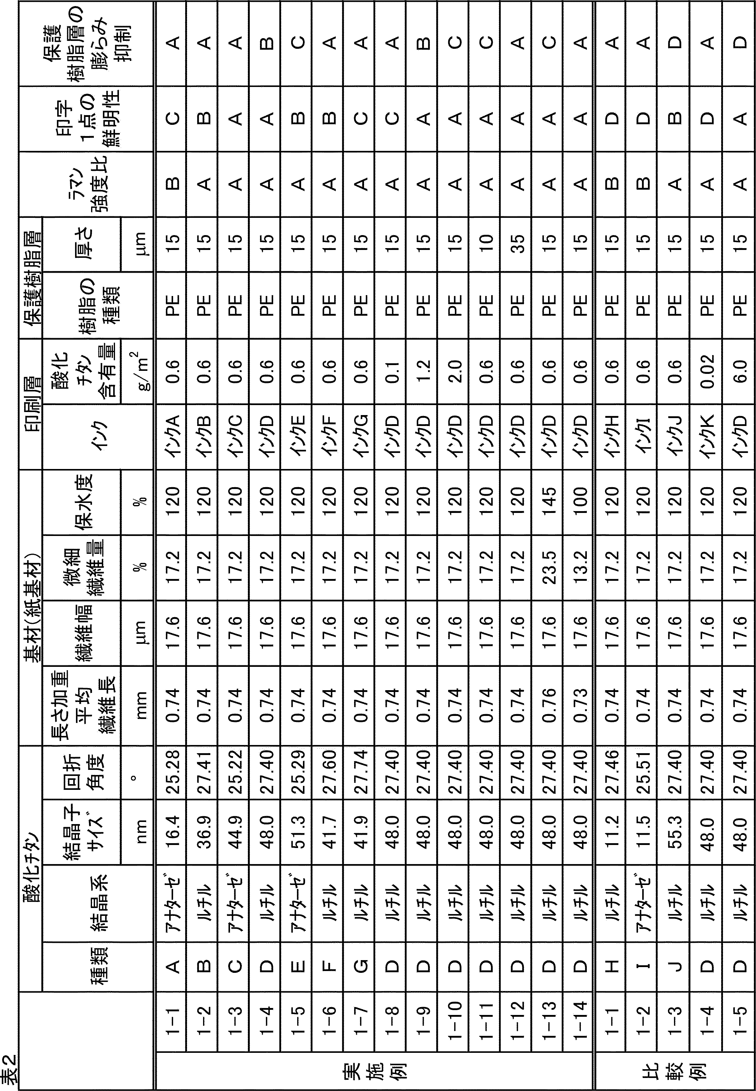
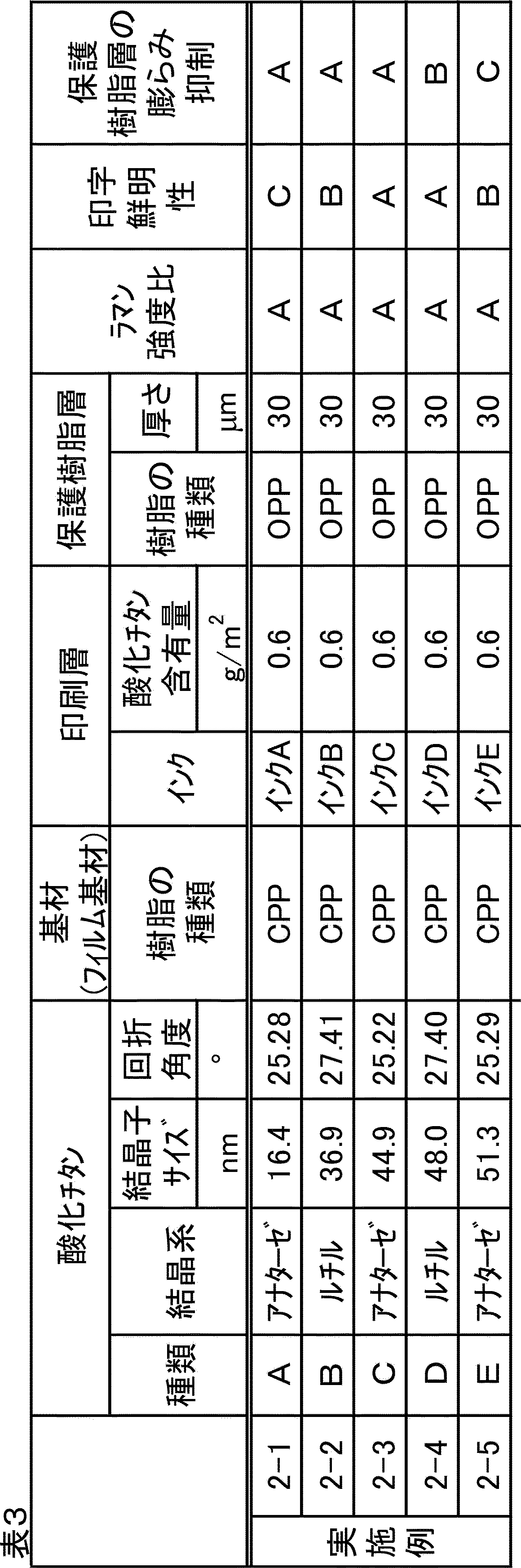
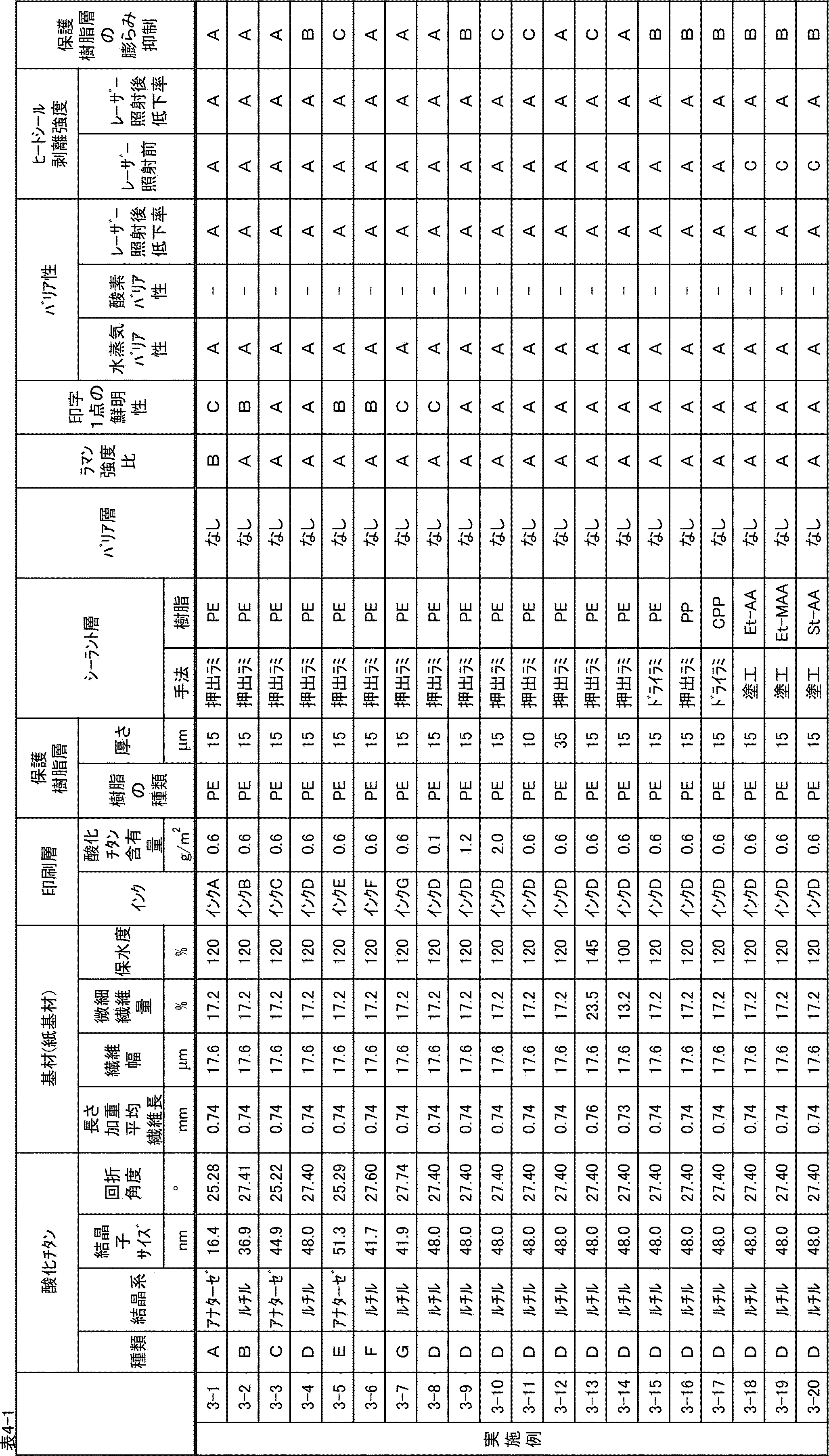
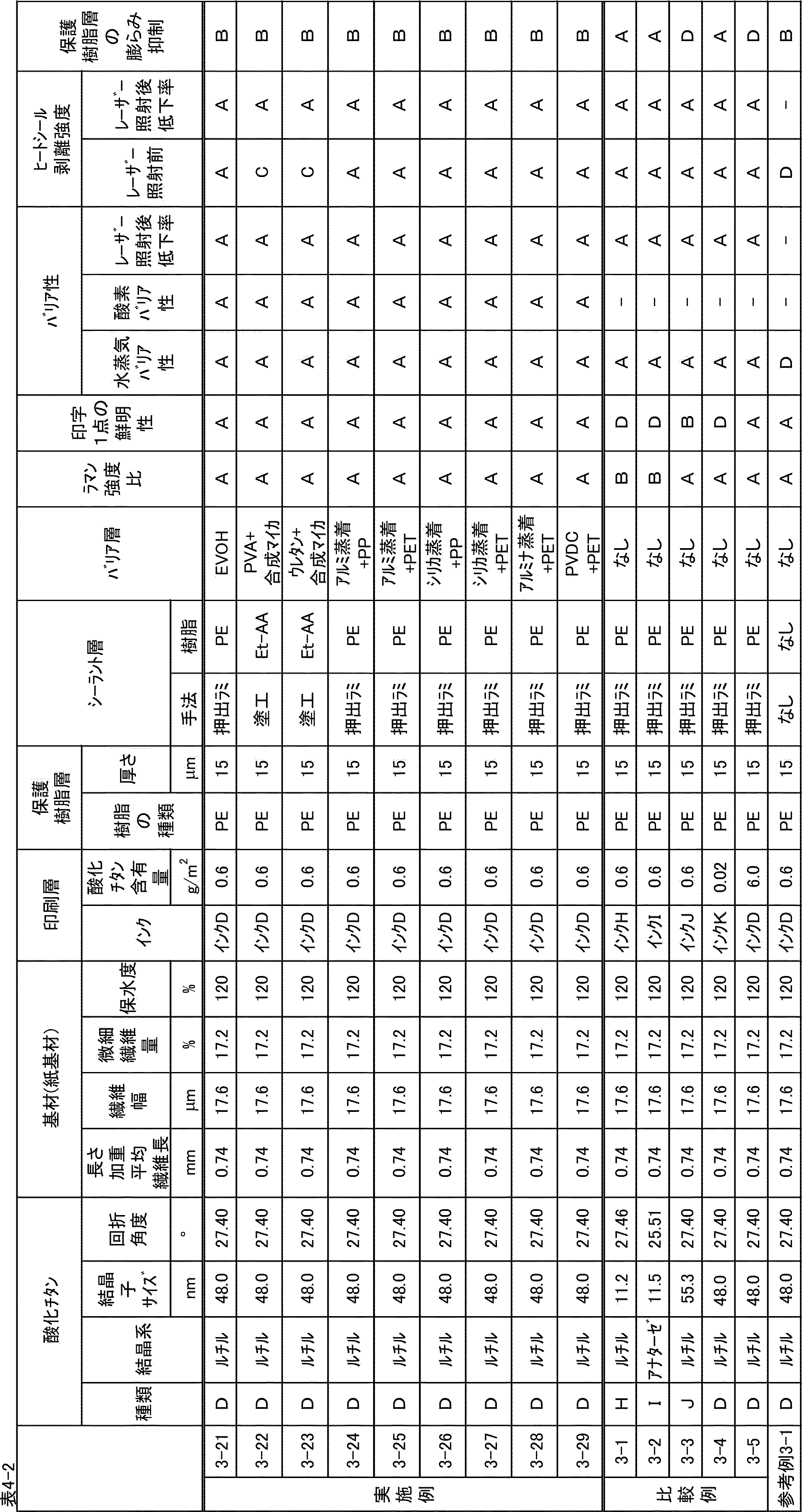
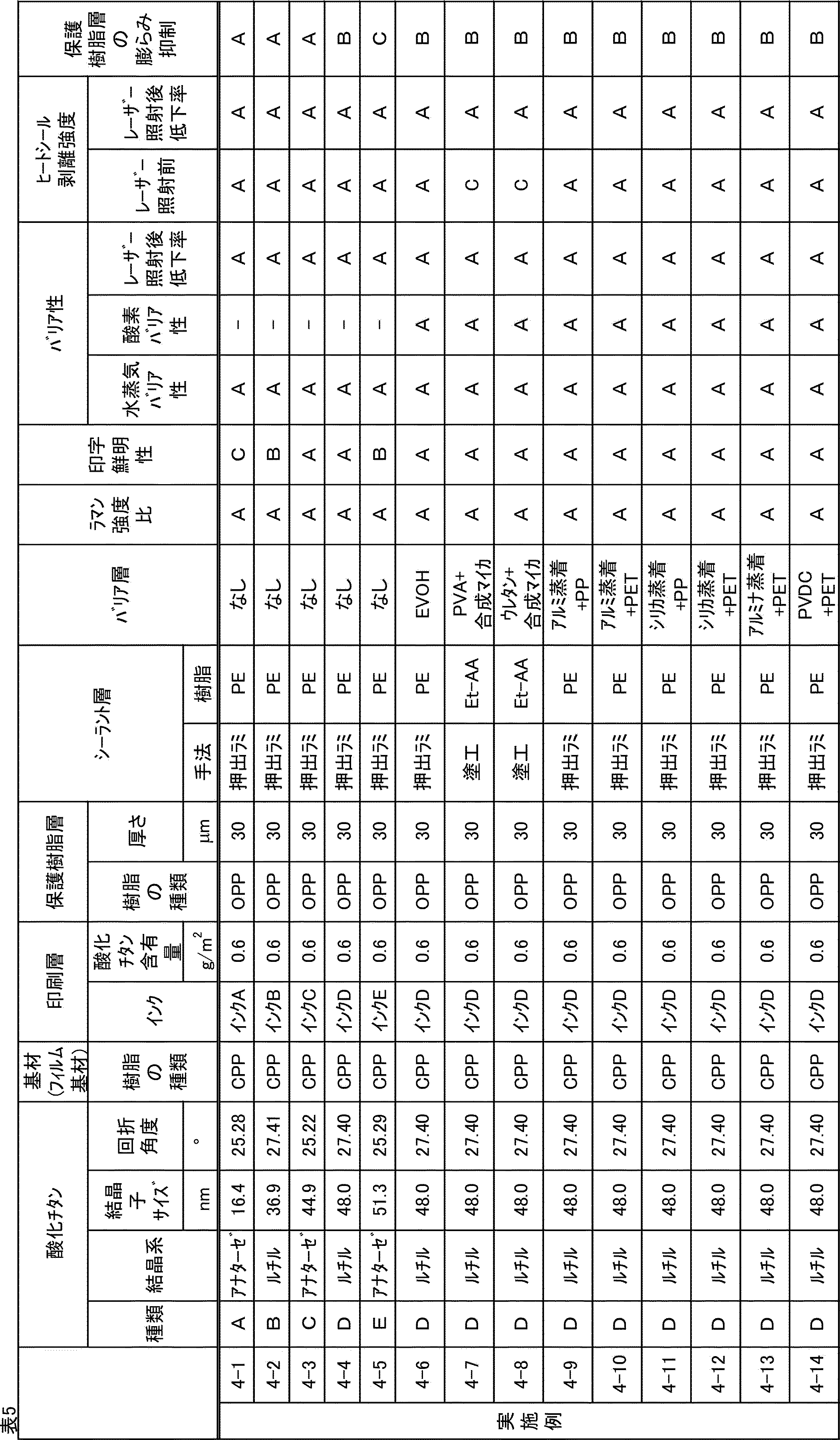
表2および3の結果によれば、実施例の印刷用媒体を用いて、紫外線レーザーにより印刷することにより、一点ごとの印字鮮明性に優れ、保護樹脂層の膨らみ抑制された印刷画像を有する印刷物が得られた。
一方、印刷層が有する酸化チタンの結晶子サイズが13nm未満である比較例1-1および比較例1-2の印刷用媒体を用いて紫外線レーザーにより印刷した場合には、十分な一点ごとの印字鮮明性が得られなかった。また、印刷層が有する酸化チタンの結晶子サイズが53nmを超える比較例1-3の印刷用媒体を用いて紫外線レーザーにより印刷した場合には、保護樹脂層の膨らみが発生した。
さらに、印刷層が有する酸化チタンの含有量が0.1g/m2未満である比較例1-4の印刷用媒体を用いて紫外線レーザーにより印刷した場合には、十分な一点ごとの印字鮮明性が得られなかった。また、印刷層が有する酸化チタンの含有量が4.0g/m2を超える比較例1-5の印刷用媒体を用いて紫外線レーザーにより印刷した場合には、保護樹脂層の膨らみが発生した。
一方、印刷層が有する酸化チタンの結晶子サイズが13nm未満である比較例1-1および比較例1-2の印刷用媒体を用いて紫外線レーザーにより印刷した場合には、十分な一点ごとの印字鮮明性が得られなかった。また、印刷層が有する酸化チタンの結晶子サイズが53nmを超える比較例1-3の印刷用媒体を用いて紫外線レーザーにより印刷した場合には、保護樹脂層の膨らみが発生した。
さらに、印刷層が有する酸化チタンの含有量が0.1g/m2未満である比較例1-4の印刷用媒体を用いて紫外線レーザーにより印刷した場合には、十分な一点ごとの印字鮮明性が得られなかった。また、印刷層が有する酸化チタンの含有量が4.0g/m2を超える比較例1-5の印刷用媒体を用いて紫外線レーザーにより印刷した場合には、保護樹脂層の膨らみが発生した。
表4および5の結果によれば、実施例の印刷用媒体を用いて、紫外線レーザーにより印刷することにより、一点ごとの印字鮮明性に優れ、保護樹脂層の膨らみ抑制された印刷画像を有する印刷物が得られた。
さらに、ヒートシール性を有し、水蒸気バリア性にも優れるものであった。また、バリア層を形成した実施例3-21~3-29および4-6~4-14の紫外線レーザー印刷用媒体は、酸素バリア性にも優れるものであった。また、紫外線レーザーによる印刷による、バリア性およびヒートシール性の低下が抑制されていた。
一方、印刷層が有する酸化チタンの結晶子サイズが13nm未満である比較例3-1および比較例3-2の印刷用媒体を用いて紫外線レーザーにより印刷した場合には、十分な一点ごとの印字鮮明性が得られなかった。また、印刷層が有する酸化チタンの結晶子サイズが53nmを超える比較例3-3の印刷用媒体を用いて紫外線レーザーにより印刷した場合には、保護樹脂層の膨らみが発生した。
さらに、印刷層が有する酸化チタンの含有量が0.1g/m2未満である比較例3-4の印刷用媒体を用いて紫外線レーザーにより印刷した場合には、十分な一点ごとの印字鮮明性が得られなかった。また、印刷層が有する酸化チタンの含有量が4.0g/m2を超える比較例1-5の印刷用媒体を用いて紫外線レーザーにより印刷した場合には、保護樹脂層の膨らみが発生した。
また、シーラント層を有していない参考例3-1の印刷用媒体を用いた場合には、ヒートシール性および水蒸気バリア性が得られなかった。
さらに、ヒートシール性を有し、水蒸気バリア性にも優れるものであった。また、バリア層を形成した実施例3-21~3-29および4-6~4-14の紫外線レーザー印刷用媒体は、酸素バリア性にも優れるものであった。また、紫外線レーザーによる印刷による、バリア性およびヒートシール性の低下が抑制されていた。
一方、印刷層が有する酸化チタンの結晶子サイズが13nm未満である比較例3-1および比較例3-2の印刷用媒体を用いて紫外線レーザーにより印刷した場合には、十分な一点ごとの印字鮮明性が得られなかった。また、印刷層が有する酸化チタンの結晶子サイズが53nmを超える比較例3-3の印刷用媒体を用いて紫外線レーザーにより印刷した場合には、保護樹脂層の膨らみが発生した。
さらに、印刷層が有する酸化チタンの含有量が0.1g/m2未満である比較例3-4の印刷用媒体を用いて紫外線レーザーにより印刷した場合には、十分な一点ごとの印字鮮明性が得られなかった。また、印刷層が有する酸化チタンの含有量が4.0g/m2を超える比較例1-5の印刷用媒体を用いて紫外線レーザーにより印刷した場合には、保護樹脂層の膨らみが発生した。
また、シーラント層を有していない参考例3-1の印刷用媒体を用いた場合には、ヒートシール性および水蒸気バリア性が得られなかった。
本発明の印刷用紙は、紫外線レーザーの照射によって酸化チタンが変色することで、視認性に優れる印刷物が提供でき、さらに、一点ごとの印字鮮明性に優れ、保護樹脂層の膨らみが抑制される。本発明の紫外線レーザー印刷用紙は、日付、バーコード等の可変情報が印刷される包装体、ラベル、および粘着テープなどの加工品に好適に適用される。さらに、本発明の印刷物の製造方法は、包装体、ラベル、粘着テープなどへの可変情報の印刷に好適に適用される。
Claims (17)
- 基材上に、酸化チタンを含有する印刷層と、保護樹脂層とをこの順で有し、
前記印刷層中の前記酸化チタンの含有量が、0.1g/m2以上4.0g/m2以下であり、
前記印刷層中の酸化チタンの結晶子サイズが13nm以上53nm以下である、
紫外線レーザー印刷用媒体。 - 前記印刷層中の前記酸化チタンの結晶子サイズが30nm以上53nm以下である、請求項1に記載の紫外線レーザー印刷用媒体。
- 印刷層中の酸化チタンがルチル型酸化チタンであり、前記酸化チタンの回折角度が27.60°以下である、請求項1に記載の紫外線レーザー印刷用媒体。
- 前記保護樹脂層の厚さが10μm以上である、請求項1に記載の紫外線レーザー印刷用媒体。
- 前記保護樹脂層を構成する樹脂が、ポリオレフィン、ポリエステルおよびポリビニルアルコールよりなる群から選択される少なくとも1つである、請求項1に記載の紫外線レーザー印刷用媒体。
- 前記基材が紙基材であり、前記紙基材を構成するパルプの保水度が140%以下である、請求項1に記載の紫外線レーザー印刷用媒体。
- 前記基材がフィルム基材である、請求項1に記載の紫外線レーザー印刷用媒体。
- フィルム基材を構成する樹脂が、ポリオレフィン、ポリエステル、およびポリ塩化ビニルよりなる群から選択される、請求項7に記載の紫外線レーザー印刷用媒体。
- 基材上の印刷層および保護層を有する面とは反対の面にシーラント層を有する、請求項1に記載の紫外線レーザー印刷用媒体。
- さらに、バリア層を有する、請求項9に記載の紫外線レーザー印刷用媒体。
- 請求項1~10のいずれか1項に記載の紫外線レーザー印刷用媒体から得られた印刷物であって、
前記印刷層が、少なくとも一部に、変色された酸化チタンを含有する印刷領域を有し、
非印刷領域における酸化チタンに由来するラマン強度に対する、印刷領域における酸化チタンに由来するラマン強度の比が0.70以下である、印刷物。 - 請求項1~10のいずれか1項に記載の紫外線レーザー印刷用媒体を用いてなる、加工品。
- 請求項11に記載の印刷物を用いてなる、加工品。
- 請求項1~10のいずれか1項に記載の紫外線レーザー印刷用媒体に紫外線レーザーを照射して、照射領域を変色させることにより印刷する工程を有する、
印刷物の製造方法。 - 前記印刷する工程が、非印刷領域における酸化チタンに由来するラマン強度に対する、印刷領域における酸化チタンに由来するラマン強度との比が0.70以下となるように紫外線レーザーを照射する工程である、請求項14に記載の印刷物の製造方法。
- 結晶子サイズが13nm以上53nm以下である酸化チタンを含有する、紫外線レーザーの照射により変色する印刷層を形成するために用いられるインク組成物。
- 前記酸化チタンがルチル型酸化チタンであり、酸化チタンの回折角度が27.60°以下である、請求項16に記載のインク組成物。
Applications Claiming Priority (4)
| Application Number | Priority Date | Filing Date | Title |
|---|---|---|---|
| JP2022080975A JP7302709B1 (ja) | 2022-05-17 | 2022-05-17 | 紫外線レーザー印刷用媒体、印刷物およびその製造方法、加工品、並びにインク組成物 |
| JP2022-080975 | 2022-05-17 | ||
| JP2023-062642 | 2023-04-07 | ||
| JP2023062642A JP7347707B1 (ja) | 2023-04-07 | 2023-04-07 | 紫外線レーザー印刷用媒体、印刷物およびその製造方法、並びに加工品 |
Publications (1)
| Publication Number | Publication Date |
|---|---|
| WO2023224035A1 true WO2023224035A1 (ja) | 2023-11-23 |
Family
ID=88835602
Family Applications (1)
| Application Number | Title | Priority Date | Filing Date |
|---|---|---|---|
| PCT/JP2023/018257 Ceased WO2023224035A1 (ja) | 2022-05-17 | 2023-05-16 | 紫外線レーザー印刷用媒体、印刷物およびその製造方法、加工品、並びにインク組成物 |
Country Status (1)
| Country | Link |
|---|---|
| WO (1) | WO2023224035A1 (ja) |
Citations (7)
| Publication number | Priority date | Publication date | Assignee | Title |
|---|---|---|---|---|
| JPH06278380A (ja) * | 1993-03-26 | 1994-10-04 | New Oji Paper Co Ltd | 熱転写記録用受像紙 |
| JPH10237319A (ja) * | 1997-02-25 | 1998-09-08 | Nippon Kayaku Co Ltd | レーザーマーキング用熱可塑性樹脂組成物、樹脂成型物及びレーザーマーキング方法 |
| JP2010536970A (ja) * | 2007-08-22 | 2010-12-02 | ビーエーエスエフ ソシエタス・ヨーロピア | レーザー感受性被覆組成物 |
| JP2020075943A (ja) * | 2018-11-05 | 2020-05-21 | サトーホールディングス株式会社 | インキ組成物、紫外線レーザマーキング用資材、レーザマーキングが施された資材の製造方法、包装物の製造方法、印字用ラベルが付された物品の製造方法およびレーザマーキング方法 |
| JP2021017042A (ja) * | 2019-07-24 | 2021-02-15 | 東洋インキScホールディングス株式会社 | 紫外線レーザーマーキング組成物 |
| JP2022037277A (ja) * | 2020-08-25 | 2022-03-09 | 株式会社シード | レーザ印字方法 |
| JP2022050447A (ja) * | 2020-05-22 | 2022-03-30 | 王子ホールディングス株式会社 | 印刷物、印刷物の製造方法、およびレーザー印刷用印刷媒体 |
-
2023
- 2023-05-16 WO PCT/JP2023/018257 patent/WO2023224035A1/ja not_active Ceased
Patent Citations (7)
| Publication number | Priority date | Publication date | Assignee | Title |
|---|---|---|---|---|
| JPH06278380A (ja) * | 1993-03-26 | 1994-10-04 | New Oji Paper Co Ltd | 熱転写記録用受像紙 |
| JPH10237319A (ja) * | 1997-02-25 | 1998-09-08 | Nippon Kayaku Co Ltd | レーザーマーキング用熱可塑性樹脂組成物、樹脂成型物及びレーザーマーキング方法 |
| JP2010536970A (ja) * | 2007-08-22 | 2010-12-02 | ビーエーエスエフ ソシエタス・ヨーロピア | レーザー感受性被覆組成物 |
| JP2020075943A (ja) * | 2018-11-05 | 2020-05-21 | サトーホールディングス株式会社 | インキ組成物、紫外線レーザマーキング用資材、レーザマーキングが施された資材の製造方法、包装物の製造方法、印字用ラベルが付された物品の製造方法およびレーザマーキング方法 |
| JP2021017042A (ja) * | 2019-07-24 | 2021-02-15 | 東洋インキScホールディングス株式会社 | 紫外線レーザーマーキング組成物 |
| JP2022050447A (ja) * | 2020-05-22 | 2022-03-30 | 王子ホールディングス株式会社 | 印刷物、印刷物の製造方法、およびレーザー印刷用印刷媒体 |
| JP2022037277A (ja) * | 2020-08-25 | 2022-03-09 | 株式会社シード | レーザ印字方法 |
Similar Documents
| Publication | Publication Date | Title |
|---|---|---|
| CN115666956B (zh) | 印刷物、印刷物的制造方法和激光印刷用印刷介质 | |
| JP7347707B1 (ja) | 紫外線レーザー印刷用媒体、印刷物およびその製造方法、並びに加工品 | |
| JP7188540B1 (ja) | 紫外線レーザー印刷用媒体、印刷物、および加工品 | |
| JP7120430B1 (ja) | 紫外線レーザー印刷用紙、印刷物、印刷物の製造方法、および紙加工品 | |
| JP7120429B1 (ja) | 紫外線レーザー印刷用紙、印刷物、加工品、および印刷物の製造方法 | |
| JP7188541B1 (ja) | 紫外線レーザー印刷用媒体、印刷物、および加工品 | |
| JP7347705B1 (ja) | 紫外線レーザー印刷用紙、印刷物およびその製造方法、並びに加工品 | |
| WO2023224035A1 (ja) | 紫外線レーザー印刷用媒体、印刷物およびその製造方法、加工品、並びにインク組成物 | |
| JP7306595B1 (ja) | 紫外線レーザー印刷用紙、印刷物、加工品、および印刷物の製造方法 | |
| WO2023224038A1 (ja) | 紫外線レーザー印刷用紙、印刷物およびその製造方法、加工品、並びにインク組成物 | |
| JP2023169867A (ja) | 紫外線レーザー印刷用紙、印刷物、加工品、および印刷物の製造方法 | |
| WO2023224037A1 (ja) | 紫外線レーザー印刷用紙、印刷物、加工品、および印刷物の製造方法 | |
| JP2022172096A (ja) | 印刷物およびレーザー印刷用印刷媒体 | |
| JP7115620B1 (ja) | 紫外線レーザー印刷用媒体、印刷物、および加工品 | |
| JP7302709B1 (ja) | 紫外線レーザー印刷用媒体、印刷物およびその製造方法、加工品、並びにインク組成物 | |
| JP7302708B1 (ja) | 紫外線レーザー印刷用紙、印刷物およびその製造方法、加工品、並びにインク組成物 | |
| JP7347706B1 (ja) | 紫外線レーザー印刷用フィルム、印刷物およびその製造方法、並びに加工品 | |
| JP2025166887A (ja) | 紫外線レーザーマーキング用インク組成物、紫外線レーザーマーキング用印刷層、紫外線レーザーマーキング用印刷媒体、並びに印刷物およびその製造方法 | |
| WO2024135758A1 (ja) | 紫外線レーザー印刷用クルパック紙および加工品 | |
| WO2023224034A1 (ja) | 紫外線レーザー印刷用フィルム、印刷物およびその製造方法、並びに加工品 |
Legal Events
| Date | Code | Title | Description |
|---|---|---|---|
| 121 | Ep: the epo has been informed by wipo that ep was designated in this application |
Ref document number: 23807637 Country of ref document: EP Kind code of ref document: A1 |
|
| NENP | Non-entry into the national phase |
Ref country code: DE |
|
| 122 | Ep: pct application non-entry in european phase |
Ref document number: 23807637 Country of ref document: EP Kind code of ref document: A1 |