WO2023224027A1 - 貯湯式給湯機 - Google Patents
貯湯式給湯機 Download PDFInfo
- Publication number
- WO2023224027A1 WO2023224027A1 PCT/JP2023/018232 JP2023018232W WO2023224027A1 WO 2023224027 A1 WO2023224027 A1 WO 2023224027A1 JP 2023018232 W JP2023018232 W JP 2023018232W WO 2023224027 A1 WO2023224027 A1 WO 2023224027A1
- Authority
- WO
- WIPO (PCT)
- Prior art keywords
- hot water
- water storage
- storage tank
- outlet
- heat exchanger
- Prior art date
- Legal status (The legal status is an assumption and is not a legal conclusion. Google has not performed a legal analysis and makes no representation as to the accuracy of the status listed.)
- Ceased
Links
Images



Classifications
-
- F—MECHANICAL ENGINEERING; LIGHTING; HEATING; WEAPONS; BLASTING
- F24—HEATING; RANGES; VENTILATING
- F24H—FLUID HEATERS, e.g. WATER OR AIR HEATERS, HAVING HEAT-GENERATING MEANS, e.g. HEAT PUMPS, IN GENERAL
- F24H1/00—Water heaters, e.g. boilers, continuous-flow heaters or water-storage heaters
- F24H1/18—Water-storage heaters
-
- F—MECHANICAL ENGINEERING; LIGHTING; HEATING; WEAPONS; BLASTING
- F24—HEATING; RANGES; VENTILATING
- F24H—FLUID HEATERS, e.g. WATER OR AIR HEATERS, HAVING HEAT-GENERATING MEANS, e.g. HEAT PUMPS, IN GENERAL
- F24H9/00—Details
Definitions
- the present disclosure relates to a hot water storage type water heater.
- Patent Document 1 discloses a hot water storage type water heater that includes a heating heat exchanger that heats hot water and a hot water storage tank that stores the hot water heated by the heating heat exchanger.
- This hot water storage type water heater heats the low-temperature hot water stored in the lower part of the hot water storage tank by flowing it into the heating heat exchanger through the outflow piping, and then passes the heated hot water through the inflow piping. Let it flow into the inside of the hot water storage tank.
- the high-temperature hot water is discharged toward the lower part of the hot water storage tank from an opening that the inflow pipe has and is arranged at an intermediate portion in the height direction of the hot water storage tank.
- the discharged high-temperature hot water flows toward the bottom of the hot water storage tank due to inertia, and then flows toward the top of the hot water storage tank due to buoyancy.
- the high-temperature hot water flows throughout the interior of the hot water tank while heating the surrounding low-temperature hot water, and the temperature of the entire hot water stored in the hot water storage tank increases.
- the opening of the outflow pipe through which hot water flows from the hot water storage tank is located below the opening of the inflow pipe through which hot water flows out to the hot water storage tank. Therefore, after the high-temperature hot water heated by the heating heat exchanger is discharged from the opening of the inflow piping toward the bottom of the hot water storage tank, the opening of the outflow piping is discharged without heating the surrounding low-temperature hot water. There is a risk that a short cycle may occur where the heat flows through the heating heat exchanger and is heated again. When a short cycle occurs, the temperature of the hot water flowing into the heating heat exchanger increases, the boiling efficiency decreases, and the energy saving performance decreases.
- the present disclosure has been made in view of the above-mentioned circumstances, and aims to provide a hot water storage type water heater with high boiling efficiency.
- a hot water storage type water heater includes a hot water storage tank that stores hot water, a heating heat exchanger that heats the hot water stored in the hot water storage tank, and a heating heat exchanger that heats the hot water stored in the hot water storage tank. It includes an outflow pipe that supplies hot water to the tank, and an inflow pipe that supplies hot water heated by the heating heat exchanger to the hot water storage tank.
- the hot water storage tank has a cylindrical tank body and a lower head plate joined to the lower end of the tank body.
- An outflow port is provided at the end of the outflow pipe inside the hot water storage tank.
- An inlet is provided at the end of the inflow pipe inside the hot water storage tank.
- the outlet is located above the joint between the tank body and the lower mirror plate.
- the inflow pipe discharges hot water downward into the hot water storage tank from the inlet.
- the vertical distance between the outlet and the joint is larger than the vertical distance between the lower end of the lower end plate and the joint.
- the high-temperature hot water heated by the heating heat exchanger has a long path from when it flows into the hot water storage tank through the inlet until it reaches the outlet. Therefore, the occurrence of a short cycle in which the hot water flowing into the hot water storage tank flows out to the heating heat exchanger without heating the surrounding hot water is suppressed. Therefore, high boiling efficiency can be ensured.
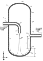
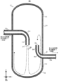
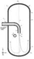
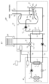
- Configuration diagram of a hot water storage type water heater according to Embodiment 1 of the present disclosure A vertical cross-sectional view of a hot water storage tank according to Embodiment 1 of the present disclosure A diagram showing an example of the flow of hot water flowing into the hot water storage tank according to Embodiment 1 of the present disclosure A diagram showing an example of the flow of hot water flowing into a hot water storage tank according to Embodiment 2 of the present disclosure A cross-sectional view of a hot water storage tank according to Embodiment 3 of the present disclosure A diagram showing an example of the flow of hot water flowing into a hot water storage tank according to Embodiment 3 of the present disclosure Configuration diagram of a hot water storage type water heater according to Embodiment 4 of the present disclosure
- the hot water storage type water heater 100 shown in FIG. 1 includes a heat pump unit 40 that heats hot water, a tank unit 50 that has a hot water storage tank 10 that stores the hot water heated by the heat pump unit 40, and operations of the heat pump unit 40 and the tank unit 50.
- a control device 70 is provided to supply hot water stored in the hot water storage tank 10 to a hot water supply destination such as a shower or a faucet.
- the heat pump unit 40 and the tank unit 50 are connected to each other via piping 21 and piping 22.
- the tank unit 50 is connected via piping 34 and piping 35 to a heating device 60 that is a hot water heating device such as a floor heating device or a hot water room heater.
- the heat pump unit 40 includes a compressor 1 that compresses a refrigerant such as carbon dioxide, R140A, and R32, a pressure reducing device 2 that reduces the pressure of the refrigerant, a heat exchanger 3 that functions as an evaporator, and supplies air to the heat exchanger 3.
- a first heating heat exchanger 5 that functions as a condenser, and a control device 6 that controls the operations of the compressor 1, the pressure reducing device 2, and the blower 4.
- the compressor 1 compresses the refrigerant and changes it into a high-temperature, high-pressure refrigerant.
- the first heating heat exchanger 5 includes a first heat medium flow path 7 through which a heat medium such as hot water and antifreeze flows, and a refrigerant flow path 8 through which a refrigerant flows, and a compressor that flows through the refrigerant flow path 8.
- the high-temperature, high-pressure refrigerant discharged from the first heat medium flow path 7 exchanges heat with the low-temperature heat medium flowing through the first heat medium flow path 7, thereby heating the heat medium.
- the pressure reducing device 2 is an expansion valve, which applies heat to the heat medium in the first heating heat exchanger 5 to reduce the pressure of the refrigerant whose temperature has dropped, thereby changing it into a low-temperature, low-pressure refrigerant.
- the heat exchanger 3 causes the low-temperature, low-pressure refrigerant discharged from the pressure reducing device 2 to absorb heat from the air, thereby heating the refrigerant.
- the control device 6 communicates with the control device 15 and the control device 70, and controls the operations of the compressor 1, the pressure reducing device 2, and the blower 4 according to the control by the control device 70.
- the compressor 1, the pressure reducing device 2, the heat exchanger 3, and the first heating heat exchanger 5 are connected in a ring through piping through which refrigerant flows, forming a refrigerant circuit 9 in which the refrigerant circulates.
- the refrigerant circuit 9 functions as a heat pump cycle that heats hot water.
- the hot water storage tank 10 included in the tank unit 50 is connected to a hot water supply destination via a hot water outlet pipe 36.
- the hot water outlet pipe 36 supplies hot water stored in the hot water storage tank 10 to a hot water supply destination.
- the hot water storage tank 10 is connected to a city water supply source via a water supply pipe 37.
- city water is supplied from the city water supply source to the hot water storage tank 10 via the water supply pipe 37.
- the tank unit 50 includes a second heating heat exchanger 11 that heats hot water stored in the hot water storage tank 10, a first pump 12 that transports a heat medium, and a second The operation of the second pump 13 that supplies the heat medium to the heating heat exchanger 11, the flow path switching device 14 that switches the flow path of the heat medium, the first pump 12, the second pump 13, and the flow path switching device 14.
- a control device 15 is provided.
- the second heating heat exchanger 11 is an example of a heating heat exchanger.
- the second heating heat exchanger 11 exchanges heat between the heat medium heated by the first heating heat exchanger 5 and the hot water supplied from the hot water storage tank 10 to boil the hot water.
- the first pump 12 causes the heat medium to flow through the first heating heat exchanger 5 and the second heating heat exchanger 11 .
- the second pump 13 sends hot water stored inside the hot water storage tank 10 to the second heating heat exchanger 11 .
- the control device 15 communicates with the control device 6 and the control device 70, and controls the operations of the first pump 12, the second pump 13, and the flow path switching device 14 according to the control by the control device 70.
- the first heating heat exchanger 5, the flow path switching device 14, the second heating heat exchanger 11, and the first pump 12 form a first heat transfer circuit 16 through which the heat medium flows.
- the second pump 13, the hot water storage tank 10, and the second heating heat exchanger 11 form a second heat transfer circuit 17 through which hot water flows.
- the heat medium flowing through the first heat transfer circuit 16 receives heat from the refrigerant flowing through the refrigerant circuit 9 and gives heat to the hot water flowing through the second heat transfer circuit 17 .
- the second heating heat exchanger 11 exchanges heat between the heat medium flowing through the first heat transfer circuit 16 and hot water flowing through the second heat transfer circuit 17 .
- the second heating heat exchanger 11 has a second heat medium flow path 18 through which the heat medium flowing through the first heat transfer circuit 16 passes, and a second heat medium flow path 18 through which hot water flows through the second heat transfer circuit 17.
- a third heat medium flow path 19 is provided, and the heat medium flowing through the second heat medium flow path 18 is caused to exchange heat with hot water flowing through the third heat medium flow path 19.
- the flow path switching device 14 includes an inlet 14a connected to the first heat medium flow path 7, and an outlet 14b connected to the second heat medium flow path 18 of the second heating heat exchanger 11. An outlet 14c connected to the heating device 60.
- the flow path switching device 14 switches the heat medium flowing through the first heat transfer circuit 16 by closing one of the outlets 14b and 14c and opening the other of the outlets 14b and 14c under the control of the control device 15. Switch the flow path.
- the first heat transfer circuit 16 connects these to each other in addition to the first heating heat exchanger 5, flow path switching device 14, second heating heat exchanger 11, and first pump 12. It includes pipes 21 to 24, and pipes 34 and 35 that interconnect the flow path switching device 14, the first pump 12, and the heating device 60.
- the pipe 21 connects the discharge side of the first pump 12 and the first heat medium flow path 7 of the first heating heat exchanger 5.
- the pipe 22 connects the first heat medium flow path 7 and the inlet 14a of the flow path switching device 14.
- the pipe 23 connects the outlet 14b of the flow path switching device 14 and the second heat medium flow path 18 included in the second heating heat exchanger 11.
- Piping 24 connects second heat medium flow path 18 and the suction side of first pump 12 .
- the pipe 34 connects the outlet 14c of the flow path switching device 14 and the heating device 60.
- the heat medium of the first heat transfer circuit 16 discharged from the outlet 14c of the flow path switching device 14 flows into the heating device 60 via the pipe 34.
- Piping 35 connects heating device 60 and the suction side of first pump 12 .
- the heat medium of the first heat transfer circuit 16 flowing out from the heating device 60 flows into the first pump 12 via the pipe 35.
- the second heat transfer circuit 17 transfers the hot water heated by the second heating heat exchanger 11 to the second heating heat exchanger 11.
- An inflow pipe 27 that supplies hot water from the heating heat exchanger 11 to the hot water storage tank 10 and an outflow pipe 28 that supplies hot water stored in the hot water storage tank 10 from the hot water storage tank 10 to the second heating heat exchanger 11.
- the inflow pipe 27 connects the discharge side of the second pump 13 and the hot water storage tank 10.
- the outflow pipe 28 connects the hot water storage tank 10 and the third heat medium flow path 19 included in the second heating heat exchanger 11 .
- the hot water storage tank 10 is made of a material such as metal or resin, and stores hot water heated by the second heating heat exchanger 11.
- FIG. 2 is a longitudinal cross-sectional view of the hot water storage tank 10 taken along a cut plane that includes the axis of the tank body 10A and is parallel to the vertical direction G.
- the hot water storage tank 10 includes a cylindrical tank body 10A, a hemispherical or bowl-shaped lower end plate 10B that is convex vertically downward and is joined to the lower end of the tank body 10A, and a tank body. It includes a hemispherical or bowl-shaped upper mirror plate 10C joined to the upper end of the portion 10A.
- the lower end of the tank body 10A and the lower mirror plate 10B are joined by welding or adhesive at a first joint 10D.
- the first joint 10D is an example of a joint.
- the upper end of the tank body 10A and the upper mirror plate 10C are joined by welding or adhesive at a second joint 10E.
- An inflow pipe 27 and an outflow pipe 28 are connected to the hot water storage tank 10.
- the hot water tap piping 36 and the water supply piping 37 are not illustrated.
- an XYZ orthogonal coordinate system shown in FIG. 2 will be set.
- the Z axis is set parallel to the vertical direction G.
- the inflow pipe 27 and the outflow pipe 28 are included in a plane parallel to the Z-axis, the X-axis is set parallel to this plane, and the Y-axis is set perpendicular to this plane.
- the X-axis direction corresponds to the left-right direction
- the Y-axis direction corresponds to the front-back direction
- the Z-axis direction corresponds to the up-down direction.
- the Z-axis direction also corresponds to the height direction of the hot water storage tank 10.
- the inflow pipe 27 is inserted into the tank body 10A at the middle part in the height direction of the hot water storage tank 10 and extends inside the hot water storage tank 10.
- the inflow pipe 27 has a horizontal portion 27a extending parallel to the horizontal direction, a vertical portion 27b provided downstream from the horizontal portion 27a and extending parallel to the vertical direction G, and a downstream end of the horizontal portion 27a and the vertical portion 27b.
- the upper end of the vertical portion 27b is located below the downstream end of the horizontal portion 27a.
- An inlet 27c through which hot water flows into the hot water storage tank 10 is provided at the lower end of the vertical portion 27b, which is the end of the inflow pipe 27 inside the hot water storage tank 10. The inlet 27c opens downward.
- the position of the inlet 27c in the vertical direction G is located lower than the position of the second joint 10E in the vertical direction G.
- the hot water flowing out from the second heating heat exchanger 11 passes through the horizontal portion 27a, the curved portion 27d, and the vertical portion 27b of the inflow pipe 27 in this order, and is discharged downward into the hot water storage tank 10 from the inflow port 27c.
- the axis of the inlet 27c coincides with the axis of the lower mirror plate 10B.
- the axis of the hemispherical or bowl-shaped lower head plate 10B passes through the lower end of the lower head plate 10B. Thereby, the hot water that has passed through the inflow pipe 27 is discharged from the inflow port 27c toward the lower end of the lower mirror plate 10B.
- the outflow pipe 28 is connected to a position below the position where the inflow pipe 27 of the tank body 10A is connected.
- the outflow pipe 28 does not extend inside the hot water storage tank 10, and the upstream end of the outflow pipe 28 is joined to the inner wall of the tank body 10A.
- An outflow port 28a through which hot water flows out from the hot water storage tank 10 is provided at an upstream end of the outflow pipe 28, which is an end of the outflow pipe 28 inside the hot water storage tank 10.
- the outlet 28a opens horizontally. Hot water in the hot water storage tank 10 flows out from the outlet 28a, passes through the outflow pipe 28, and flows into the second heating heat exchanger 11.
- the inlet 27c is located above the outlet 28a.
- the outflow port 28a is arranged at a position shifted from the direction of hot water discharge from the inflow port 27c, avoiding the direction of hot water discharge.
- the horizontal distance between the inlet 27c and the outlet 28a is such that hot water discharged from the inlet 27c is prevented from directly flowing into the outlet 28a.
- the horizontal distance between the inlet 27c and the outlet 28a is set to a value larger than the distance over which the hot water discharged from the inlet 27c spreads in the horizontal direction before reaching the lower mirror plate 10B.
- the outlet 28a is located above the first joint 10D, which is the joint between the tank body 10A and the lower mirror plate 10B.
- the axis of the outlet 28a and the axis of the tank body 10A are included in a plane that includes the axis of the inlet 27c and is parallel to the vertical direction G.
- the vertical distance L1 between the outlet 28a and the first joint 10D is larger than the vertical distance L2 between the lower end of the lower mirror plate 10B and the first joint 10D.
- each temperature sensor is electrically connected to the control device 70, detects the temperature of hot water inside the hot water storage tank 10 at the position where each temperature sensor is installed, and sends an output signal indicating the detection result to the control device 70. do.
- the control device 70 includes a processor that executes various processes and a memory that stores data and programs.
- the processor of the control device 70 functions as an operation control means that controls the operations of the heat pump unit 40 and the tank unit 50 by executing a program stored in the memory.
- the control device 70 causes the control device 6 to control the operation of the heat pump unit 40 and the control device 15 to control the operation of the tank unit 50 by transmitting control signals to the control device 6 and the control device 15.
- the control device 70 constantly monitors the amount of remaining hot water and the amount of heat storage inside the hot water storage tank 10.
- the control device 70 detects the temperature distribution along the vertical direction of the hot water stored in the hot water storage tank 10 based on the output signals received from the five temperature sensors described above, thereby controlling the amount of remaining hot water and heat storage inside the hot water storage tank 10. Detect amount.
- the control device 70 controls whether the hot water storage type A water heater 100 is caused to perform a boiling operation for heating hot water stored in a hot water storage tank 10.
- the refrigerant flowing through the refrigerant circuit 9 heats the heat medium flowing through the first heat transfer circuit 16, and the heated heat medium flowing through the first heat transfer circuit 16 heats the heat medium flowing through the second heat transfer circuit 16. Heat the hot water flowing through 17.
- the hot water flowing through the heated second heat transfer circuit 17 is stored in the hot water storage tank 10.
- the refrigerant in the refrigerant circuit 9, the refrigerant is compressed and discharged by the compressor 1, flows into the refrigerant passage 8 of the first heating heat exchanger 5, and in the process of passing through the refrigerant passage 8, the refrigerant is compressed and discharged by the compressor 1.
- the heat medium of the first heat transfer circuit 16 flowing through the first heat medium flow path 7 is heated.
- the refrigerant liquefies while passing through the refrigerant flow path 8 .
- the refrigerant flowing out from the refrigerant flow path 8 flows into the pressure reducing device 2, is depressurized by the pressure reducing device 2, and changes into a gas-liquid two-phase state.
- the refrigerant flowing out of the pressure reducing device 2 flows into the heat exchanger 3 and absorbs heat from the air around the heat pump unit 40 .
- the refrigerant vaporizes while passing through the heat exchanger 3.
- the refrigerant flowing out from the heat exchanger 3 returns to the compressor 1.
- the heat medium is pressurized and discharged by the first pump 12, and is sent to the first heat medium flow path 7 of the first heating heat exchanger 5 via piping 21.
- the refrigerant is heated by the refrigerant of the refrigerant circuit 9 flowing through the refrigerant flow path 8 .
- the heat medium flowing out of the first heat medium flow path 7 flows into the inlet 14a of the flow path switching device 14 via the pipe 22.
- the flow path switching device 14 closes the outlet 14c and opens the outlet 14b under the control of the control device 15.
- the heat medium that has flowed into the inlet 14a of the flow path switching device 14 flows out from the outlet 14b.
- the heat medium flowing out from the outlet 14b flows into the second heat medium flow path 18 of the second heating heat exchanger 11 via the pipe 23, and in the process of passing through the second heat medium flow path 18, the heat medium flows into the second heat medium flow path 18 of the second heat exchanger 11 for heating.
- the hot water flowing through the heat medium flow path 19 of No. 3 is heated.
- the heat medium flowing out from the second heat medium flow path 18 returns to the first pump 12 via the piping 24.
- the hot water stored in the hot water storage tank 10 flows into the third heat medium flow path 19 of the second heating heat exchanger 11 via the outflow pipe 28, and flows into the third heat medium flow path 19 of the second heating heat exchanger 11.
- it is heated by the heat medium of the first heat transfer circuit 16 flowing through the second heat medium flow path 18.
- the hot water flowing out from the third heat medium flow path 19 flows into the second pump 13 via the pipe 26.
- the hot water that has flowed into the second pump 13 is pressurized and discharged by the second pump 13, and flows into the hot water storage tank 10 via the inflow pipe 27.
- the hot water flowing into the hot water storage tank 10 heats the hot water stored in the hot water storage tank 10.
- FIG. 3 is a diagram showing an example of the flow of hot water flowing into the hot water storage tank 10.
- FIG. 3 shows a longitudinal section of the hot water storage tank 10 taken along a cut plane that includes the axis of the tank body 10A and is parallel to the vertical direction G.
- Arrow AA in FIG. 3 indicates the flow of hot water.
- the inflow pipe 27 discharges hot water downward into the hot water storage tank 10 from an inflow port 27c. The discharged hot water flows downward due to inertia, collides with or contacts the lower head plate 10B of the hot water storage tank 10, and then flows upward along the lower head plate 10B and the inner wall of the tank body 10A due to buoyancy.
- the hot water that flows upward and reaches the outlet 28a of the outlet pipe 28 flows out from the outlet 28a and flows into the second heating heat exchanger 11 via the outlet pipe 28.
- the hot water that has flowed into the hot water storage tank 10 via the inflow pipe 27 is high-temperature hot water that has been heated by the second heating heat exchanger 11, and in the process of flowing inside the hot water storage tank 10 along the above-mentioned path. Heats the surrounding low-temperature water.
- the vertical distance L1 between the outlet 28a and the first joint 10D is larger than the vertical distance L2 between the lower end of the lower mirror plate 10B and the first joint 10D.
- the high-temperature hot water heated by the second heating heat exchanger 11 has a long path from flowing into the hot water storage tank 10 through the inlet 27c until reaching the outlet 28a. It takes a long time for high-temperature hot water to flow into the hot water storage tank 10 until it flows out to the second heating heat exchanger 11. That is, according to such a configuration, it takes a long time to heat the surrounding low-temperature hot water from when the high-temperature hot water flows into the hot water storage tank 10 until it flows out to the second heating heat exchanger 11.
- the inlet 27c and the outlet 28a are arranged in a positional relationship that prevents hot water discharged from the inlet 27c from directly flowing into the outlet 28a. Therefore, the occurrence of short cycles is suppressed.
- the position and opening direction of the outlet 28a are not limited to the positions and opening directions shown in FIGS. 2 and 3, and can be set arbitrarily.
- the inflow pipe 27 and the outflow pipe 28 are arranged on the same plane that includes the axis of the tank body 10A, but this is only an example;
- the outflow pipes 28 may be configured to extend on different planes.
- the position and opening direction of the outflow port 28a are shifted from the position and opening direction where hot water discharged from the inflow port 27c is prevented from directly flowing into the outflow port 28a, for example, from the direction in which hot water is discharged from the inflow port 27c. It is preferable to set the position and the opening direction that intersects with the discharge direction.
- the outflow port 28a may be arranged to avoid an area in which the hot water discharged from the inflow port 27c diffuses in the horizontal direction before reaching the height of the outflow pipe 28, as determined by experiment or simulation. It is preferable that the hot water discharged from the inlet 27c is disposed so as to avoid an area where hot water is diffused before reaching the lower mirror plate 10B.
- the arrangement position of the outlet 28a at which the amount of hot water directly flowing into the outlet 28a is negligibly small may be determined by experiment or simulation.
- the ratio of the amount of hot water directly flowing into the outlet 28a to the amount of hot water discharged from the inlet 27c is equal to the reference value.
- One example is 15% or less, more preferably 10% or less.
- the above-mentioned reference value is not limited to 15%.
- the reference value is preferably 5% or less. This suppresses hot water discharged from the inlet 27c from directly flowing into the outlet 28a.
- the outlet 28a opens in the wall of the hot water storage tank 10.
- the present disclosure is not limited to this example.
- the second embodiment, in which the outflow pipe 28 extends into the hot water storage tank 10 and the outflow port 28a opens upward, will be described below, focusing on the differences from the first embodiment.
- FIG. 4 is a diagram showing an example of the flow of hot water flowing into the hot water storage tank 10 according to the second embodiment.
- FIG. 4 shows a longitudinal section of the hot water storage tank 10 according to the present embodiment, which is cut along a cut plane that includes the axis of the tank body 10A and is parallel to the vertical direction G.
- the outflow pipe 28 according to the present embodiment extends into the hot water storage tank 10 through a through hole provided in the middle part of the hot water storage tank 10 in the height direction.
- the outflow pipe 28 has a horizontal part 28b extending parallel to the horizontal direction, a vertical part 28c provided upstream of the horizontal part 28b and extending parallel to the vertical direction G, and an upstream end of the horizontal part 28b and the vertical part 28c.
- the lower end of the vertical portion 28c is located above the upstream end of the horizontal portion 28b.
- An outflow port 28a is provided at the upper end of a vertical portion 28c, which is the end of the outflow pipe 28 inside the hot water storage tank 10.
- the outflow port 28a is located below the inflow port 27c.
- the outlet 28a opens upward.
- the outlet 28a is an outlet for hot water that has come into contact with the lower end plate 10B after being discharged from the inlet 27c to flow into the outlet 28a, and an outlet for hot water that has not come into contact with the lower end plate 10B after being discharged from the inlet 27c. It is arranged at a position where the inflow into 28a is suppressed, for example, at a position shifted from the direction in which hot water is discharged from the inlet 27c.
- Arrow BB in FIG. 4 indicates the flow of hot water.
- the inflow pipe 27 discharges high-temperature hot water heated by the second heating heat exchanger 11 downward into the hot water storage tank 10 from an inflow port 27c, as shown in FIG.
- the discharged hot water flows downward due to inertia, collides with the lower head plate 10B, and then flows upward along the lower head plate 10B and the inner wall of the tank body 10A due to buoyancy.
- the hot water flowing upward reaches a position above the outlet 28a, it flows downward due to gravity, reaches the outlet 28a that is opened upward, flows out from the outlet 28a, and flows through the outlet piping 28. and flows into the second heating heat exchanger 11.
- the high temperature hot water supplied by the inflow pipe 27 heats the surrounding low temperature hot water while flowing inside the hot water storage tank 10 along the above-described path.
- the path taken by high-temperature hot water from flowing into the hot water storage tank 10 through the inlet 27c until reaching the outlet 28a is long, and the path taken after the high-temperature hot water flows into the hot water storage tank 10 and then reaching the hot water storage tank 10 is long. It takes a long time to flow out to the heating heat exchanger 11 of No. 2. That is, according to such a configuration, it takes a long time to heat the surrounding low-temperature hot water from when the high-temperature hot water flows into the hot water storage tank 10 until it flows out to the second heating heat exchanger 11. Thereby, the occurrence of a short cycle is suppressed, and the rise in the temperature of the hot water flowing into the second heating heat exchanger 11 is suppressed. Therefore, boiling efficiency is high and energy saving performance is high.
- FIG. 5 is a cross-sectional view of the hot water storage tank 10 cut along a cut plane that includes the outlet 28a and is orthogonal to the vertical direction G. Further, FIG. 6 is a sectional view taken along the line DD in FIG. 5.
- the horizontal portion 27a of the inflow pipe 27 extends in the X-axis direction. Further, as shown in FIG. 6, the vertical portion 27b extends in the vertical direction G.
- the inflow pipe 27 discharges hot water from the inflow port 27c in a direction inclined from the vertical direction G to the +X-axis direction.
- the +X-axis direction is an example of the first direction.
- causes for discharging hot water in a direction inclined in the +X-axis direction include centrifugal force being applied to the hot water when the hot water passes through the curved portion 27d, or vertical portion 27b being inclined from the vertical direction G.
- the high temperature hot water is discharged into the hot water storage tank 10 in a biased state in the +X-axis direction with respect to the axis CC of the inlet 27c.
- the flow rate of high-temperature hot water flowing in the +X-axis direction inside the hot water storage tank 10 is smaller than the flow rate of high-temperature hot water flowing in the -X-axis direction.
- the outflow port 28a is disposed away from the axis CC of the inflow port 27c in the ⁇ X-axis direction on the DD line cross section in order to suppress the direct inflow of hot water discharged from the inflow port 27c.
- the ⁇ X-axis direction is an example of the second direction.
- the high-temperature hot water that flows into the hot water storage tank 10 from the inlet 27c takes a long path before reaching the outlet 28a. This suppresses the occurrence of short cycles.
- the position of the outlet 28a is not limited to the positions shown in FIGS. 5 and 6, and can be selected as appropriate.
- the hot water storage type water heater 100 includes a second outflow pipe 29 that supplies hot water from the hot water storage tank 10 to the second heating heat exchanger 11, and either the outflow pipe 28 or the second outflow pipe 29 Embodiment 4 of the present disclosure, in which hot water is supplied to the second heating heat exchanger 11 via one side, will be described with a focus on the differences from Embodiment 1.
- the tank unit 50 switches the flow path of hot water with a second outflow pipe 29 that supplies hot water from the hot water storage tank 10 to the second heating heat exchanger 11.
- a second flow path switching device 30 an outgoing pipe 31 that connects the second flow path switching device 30 and the second heating heat exchanger 11 , and a temperature sensor that detects the temperature of hot water in the hot water storage tank 10
- the tank unit 50 is different from the tank unit 50 according to the first embodiment in that it includes the following.
- the second outflow pipe 29 is connected to a position below the position where the outflow pipe 28 of the tank body 10A is connected.
- the second outflow pipe 29 does not extend inside the hot water storage tank 10, and the upstream end of the second outflow pipe 29 is joined to the inner wall of the tank body 10A.
- a second outflow port 29a through which hot water flows out from the hot water storage tank 10 is provided at the upstream end of the second outflow pipe 29, which is the end of the second outflow pipe 29 inside the hot water storage tank 10.
- the second outlet 29a opens in the horizontal direction.
- the second outlet 29a is located below the outlet 28a.
- the axis of the second outlet 29a includes the axis of the inlet 27c as well as the axis of the outlet 28a and the tank body 10A, and is included in a plane JJ parallel to the vertical direction G. ing.
- the second outflow port 29a is configured such that the hot water that has come into contact with the lower mirror plate 10B after being discharged from the inlet 27c flows into the second outlet 29a, and that the hot water that has come into contact with the lower mirror plate 10B after being discharged from the inflow port 27c. It is arranged at a position where the flow of unused hot water into the second outlet 29a is suppressed, that is, at a position shifted from the direction in which hot water is discharged from the outlet 27c. Specifically, the distance in the horizontal direction between the inlet 27c and the second outlet 29a is greater than the distance over which the hot water discharged from the inlet 27c spreads in the horizontal direction before reaching the lower mirror plate 10B.
- the second flow path switching device 30 is connected to the outflow pipe 28 and the second outflow pipe 29. Specifically, the second flow path switching device 30 has an inlet 30a connected to the outflow pipe 28, an inlet 30b connected to the second outflow pipe 29, an outlet 30c connected to the outflow pipe 31, It is equipped with The second flow path switching device 30 closes one of the inlets 30a and 30b and opens the other of the inlets 30a and 30b under the control of the control device 15, thereby allowing the flow of hot water flowing out from the hot water storage tank 10. Switch roads.
- the temperature sensor 32 is a temperature sensor such as a thermocouple or a thermistor, and is attached to the hot water storage tank 10 to detect the temperature of hot water in the hot water storage tank 10. Specifically, the temperature sensor 32 is disposed at a reference position located below the outflow port 28a and above the second outflow port 29a, and the temperature sensor 32 is disposed at a reference position located below the outflow port 28a and above the second outflow port 29a. Detects the temperature of The temperature sensor 32 is electrically connected to the control device 70 and transmits an output signal indicating the detection result of the temperature of hot water to the control device 70.
- the control device 70 causes the control device 15 included in the tank unit 50 to control the operation of the second flow path switching device 30.
- the control device 70 switches the flow path of the hot water supplied from the hot water storage tank 10 to the second heating heat exchanger 11 according to the temperature distribution of hot water in the hot water storage tank 10 along the vertical direction.
- city water which is low-temperature hot water
- city water which is low-temperature hot water
- the low temperature hot water that has flowed into the hot water storage tank 10 forms a layer at the bottom of the hot water storage tank 10, and the high temperature hot water forms a layer above this low temperature hot water.
- temperature distribution 1 the temperature distribution in which the boundary surface between the high temperature hot water layer and the low temperature hot water layer is located above the outlet 28a
- temperature distribution 2 the temperature distribution in which the temperature distribution is located below the outlet 28a
- the control device 70 detects the temperature distribution of the hot water in the hot water storage tank 10 based on the temperature of the hot water at the reference position in the hot water storage tank 10 detected by the temperature sensor 32, and controls the flow path of the hot water according to the detected temperature distribution. Control.
- the control device 70 controls the temperature distribution of the hot water in the hot water storage tank 10 to be the temperature distribution. It is determined that it is 1. If the temperature of the hot water in the hot water storage tank 10 at the reference position detected by the temperature sensor 32 is lower than the reference temperature, the control device 70 determines that the temperature distribution of the hot water in the hot water storage tank 10 is temperature distribution 2.
- the reference temperature corresponds to a temperature that serves as a standard for classifying high-temperature hot water and low-temperature hot water, and is set to 40 [° C.] in this embodiment. Note that this is just an example, and the reference temperature can be set arbitrarily.
- control device 70 determines that the temperature distribution of hot water in the hot water storage tank 10 is temperature distribution 1
- the control device 70 controls the second flow path switching device 30 to open the inlet 30a and close the inlet 30b.
- the flow path of hot water is controlled so that hot water flows through the outflow pipe 28 and the outgoing pipe 31, but does not flow through the second outflow pipe 29.
- hot water is supplied to the second heating heat exchanger 11 via the outflow pipe 28 without being supplied to the second heating heat exchanger 11 via the second outflow pipe 29. .
- the control device 70 determines that the temperature distribution of hot water in the hot water storage tank 10 is temperature distribution 2
- the control device 70 controls the second flow path switching device 30 to open the inlet 30b and close the inlet 30a.
- the flow path of hot water is controlled so that hot water flows through the second outflow pipe 29 and the outgoing pipe 31 and hot water does not flow through the outflow pipe 28.
- hot water is not supplied to the second heating heat exchanger 11 via the outflow pipe 28, but hot water is supplied to the second heating heat exchanger 11 via the second outflow pipe 29. .
- the hot water existing near the outlet 28a and the hot water existing near the second outlet 29a are both low-temperature hot water.
- the hot water flow path is controlled so that the hot water in the hot water storage tank 10 flows out from the outflow port 28a without flowing out from the second outflow port 29a. It takes a long path from flowing into the hot water to passing through a layer of low-temperature hot water to reaching the outlet 28a. Therefore, it takes a long time to heat the surrounding low-temperature hot water from when the high-temperature hot water flows into the hot water storage tank 10 until it flows out to the second heating heat exchanger 11. Therefore, boiling efficiency is high.
- Temperature distribution 2 is a temperature distribution in which the interface between the high temperature hot water layer and the low temperature hot water layer is located below the outlet 28a and above the second outlet 29a. , and a temperature distribution in which this boundary surface is located below the second outlet 29a.
- temperature distribution 2A the former temperature distribution
- temperature distribution 2B the latter temperature distribution
- the hot water existing near the outlet 28a is high temperature hot water
- the hot water existing near the second outlet 29a is low temperature hot water. be.
- the hot water flow path is controlled so that the hot water in the hot water storage tank 10 flows out from the second outflow port 29a without flowing out from the outflow port 28a. Outflow to the heating heat exchanger 11 is suppressed. Therefore, boiling efficiency is high.
- the hot water existing near the outlet 28a and the hot water existing near the second outlet 29a are both high-temperature hot water.
- the hot water flow path is controlled so that the hot water in the hot water storage tank 10 does not flow out from the outflow port 28a but flows out from the second outflow port 29a, so that the hot water flows into the hot water storage tank 10 through the inflow port 27c.
- the path taken by hot water until it flows out from the hot water storage tank 10 is short. Therefore, the time for the inflowing hot water to flow inside the layer of high temperature hot water is short. Therefore, boiling efficiency is high.
- the hot water storage type water heater 100 includes the second outflow pipe 29 that supplies hot water from the hot water storage tank 10 to the second heating heat exchanger 11.
- a second outlet 29a is provided at the end of the second outlet pipe 29 inside the hot water storage tank 10.
- the second outlet 29a is located below the outlet 28a.
- Hot water is supplied to the second heating heat exchanger 11 via the outflow pipe 28 without supplying hot water to the second heating heat exchanger 11 via the second outflow pipe 29.
- the hot water storage type water heater 100 When the temperature of hot water in the hot water storage tank 10 at the reference position is lower than the reference temperature, the hot water storage type water heater 100 does not supply hot water to the second heating heat exchanger 11 via the outflow piping 28 . Hot water is supplied to the second heating heat exchanger 11 through the outflow pipe 29 . According to such a configuration, the boiling efficiency is high regardless of the temperature distribution of hot water in the hot water storage tank 10.
- the horizontal distance between the inlet 27c and the outlet 28a is longer than the distance over which the hot water discharged from the inlet 27c spreads in the horizontal direction before reaching the lower mirror plate 10B.
- the outlet 28a is an outlet for hot water that has come into contact with the lower end plate 10B after being discharged from the inlet 27c to flow into the outlet 28a, and an outlet for hot water that has not come into contact with the lower end plate 10B after being discharged from the inlet 27c. It can be placed at any position where the flow into 28a is suppressed.
- the outflow port 28a may be arranged above the inflow port 27c.
- the outflow pipe 28 was described as not extending inside the hot water storage tank 10, but this is only an example, and the outflow pipe 28 is provided in the hot water storage tank 10.
- the hot water storage tank 10 may extend into the hot water storage tank 10 by penetrating the through hole.
- the outflow port 28a of the outflow pipe 28 allows the hot water that comes into contact with the lower mirror plate 10B after being discharged from the inflow port 27c to flow into the outflow port 28a, as in the second embodiment. It is preferable to arrange the hot water at a position where hot water that is not in contact with the lower mirror plate 10B is prevented from flowing into the outlet 28a after being discharged from the lower mirror plate 10B. According to such a configuration, the boiling efficiency is high.
- five temperature sensors are attached to the hot water tank 10, but this is just an example, and the number of temperature sensors may be any number greater than or equal to two.
- the second outflow pipe 29 is explained as not extending inside the hot water storage tank 10, but this is only an example, and the second outflow pipe 29 is not extended inside the hot water storage tank 10.
- the hot water storage tank 10 may extend into the hot water storage tank 10 by passing through a through hole provided in the hot water storage tank 10 .
- the second outflow port 29a of the second outflow pipe 29 is similar to the outflow port 28a according to the second embodiment, in which hot water that has come into contact with the lower mirror plate 10B after being discharged from the inflow port 27c is connected to the second outflow port 29a.
- the hot water it is preferable to arrange the hot water at a position where the hot water that has flowed into the second outflow port 29a and is not in contact with the lower mirror plate 10B after being discharged from the inflow port 27c is suppressed from flowing into the second outflow port 29a.
- the second outlet 29a may be opened upward, similar to the outlet 28a according to the second embodiment. According to such a configuration, the boiling efficiency is high.
- the second outflow pipe 29 is connected to the tank body 10A of the hot water storage tank 10, but this is only an example, and the second outflow pipe 29 is connected to the hot water storage tank 10A. 10 may be connected to the lower end plate 10B.
- the control device 70 detects the temperature distribution of hot water in the hot water storage tank 10 based on the temperature of hot water in the hot water storage tank 10 at the reference position detected by the temperature sensor 32, and determines the temperature distribution of hot water in the hot water storage tank 10 based on the temperature of hot water in the hot water storage tank 10 at the reference position detected by the temperature sensor 32
- the explanation has been made assuming that the flow path of hot water flowing out from the hot water storage tank 10 is switched, this is only an example.
- the control device 70 detects the temperature distribution of the hot water in the hot water storage tank 10 based on the output signals output from the five temperature sensors described in the first embodiment, and switches the flow path of the hot water according to the detection result. It's okay. According to such a configuration, the boiling efficiency is high.
- Embodiments 1 to 4 above can be arbitrarily combined with each other.
- the outlet 28a may be configured to open upward. According to such a configuration, the boiling efficiency is high.
- the inflow pipe 27 discharges hot water from the inlet 27c in a direction inclined from the vertical direction G to the first direction.
- the outlet 28a may be configured to be located away from the axis CC of the inlet 27c in a second direction different from the first direction. According to such a configuration, the boiling efficiency is high.
- the inflow pipe 27 discharges hot water from the inflow port 27c in a direction inclined from the vertical direction G to the first direction, and the second outflow port 28c is connected to the axis CC of the inflow port 27c. It may be configured to be located away from the first direction in a second direction different from the first direction. According to such a configuration, the boiling efficiency is high.
Landscapes
- Engineering & Computer Science (AREA)
- Physics & Mathematics (AREA)
- Thermal Sciences (AREA)
- Chemical & Material Sciences (AREA)
- Combustion & Propulsion (AREA)
- Mechanical Engineering (AREA)
- General Engineering & Computer Science (AREA)
- Heat-Pump Type And Storage Water Heaters (AREA)
Abstract
貯湯式給湯機は、貯湯タンク(10)から第2の加熱用熱交換器(11)へ湯水を供給する流出配管(28)を備える。貯湯タンク(10)は、円筒状のタンク胴部(10A)と、タンク胴部(10A)の下端に接合された下鏡板(10B)と、を有している。流出配管(28)の貯湯タンク(10)内の端部に流出口(28a)が設けられている。流入配管(27)の貯湯タンク(10)内の端部に流入口(27c)が設けられている。流出口(28a)は、タンク胴部(10A)と下鏡板(10B)との接合部である第1の接合部(10D)よりも上に位置している。流入配管(27)は、流入口(27c)から下向きに貯湯タンク(10)内へ湯水を吐出する。流出口(28a)と第1の接合部(10D)との鉛直方向の距離(L1)は、下鏡板(10B)の下端と第1の接合部(10D)との鉛直方向の距離(L2)よりも大きい。
Description
本開示は、貯湯式給湯機に関する。
湯水を貯留する貯湯タンクを備え、貯湯タンクに貯留された湯水をシャワー、蛇口等の給湯先へ給湯する貯湯式給湯機が知られている。例えば、特許文献1には、湯水を加熱する加熱用熱交換器と、加熱用熱交換器により加熱された湯水を貯留する貯湯タンクと、を備える貯湯式給湯機が開示されている。
この貯湯式給湯機は、貯湯タンクの下部に貯留された低温の湯水を、流出配管を介して加熱用熱交換器へ流入させて加熱し、加熱された高温の湯水を、流入配管を介して貯湯タンクの内部へ流入させる。高温の湯水は、流入配管が有する、貯湯タンクの高さ方向中間部に配置された開口部から貯湯タンクの下部へ向かって吐出される。吐出された高温の湯水は、慣性によって貯湯タンクの下部へ向かって流動した後、浮力によって貯湯タンクの上部へ向かって流動する。これにより、高温の湯水が、周囲の低温の湯水を加熱しつつ貯湯タンクの内部全体を流動し、貯湯タンクに貯留された湯水全体の温度が上昇する。
特許文献1に記載された技術では、流出配管が有する、貯湯タンクから湯水が流入する開口部が、流入配管が有する、貯湯タンクへ湯水が流出する開口部よりも下に位置している。このため、加熱用熱交換器により加熱された高温の湯水が、流入配管の開口部から貯湯タンクの下部へ向かって吐出された後、周囲の低温の湯水を加熱することなく流出配管の開口部を通じて加熱用熱交換器へ流出し再度加熱されるショートサイクルが発生してしまう虞がある。ショートサイクルが発生すると、加熱用熱交換器へ流入する湯水の温度が上昇し、沸き上げ効率が低下し、省エネ性能が低下してしまう。
本開示は、上述の事情に鑑みてなされたものであり、高い沸き上げ効率を有する貯湯式給湯機を提供することを目的とする。
上記目的を達成するため、本開示に係る貯湯式給湯機は、湯水を貯留する貯湯タンクと、貯湯タンクに貯留された湯水を加熱する加熱用熱交換器と、貯湯タンクから加熱用熱交換器へ湯水を供給する流出配管と、加熱用熱交換器により加熱された湯水を貯湯タンクへ供給する流入配管と、を備えている。貯湯タンクは、円筒状のタンク胴部と、タンク胴部の下端に接合された下鏡板と、を有している。流出配管の貯湯タンク内の端部に流出口が設けられている。流入配管の貯湯タンク内の端部に流入口が設けられている。流出口は、タンク胴部と下鏡板との接合部よりも上に位置している。流入配管は、流入口から下向きに貯湯タンク内へ湯水を吐出する。流出口と接合部との鉛直方向の距離は、下鏡板の下端と接合部との鉛直方向の距離よりも大きい。
上記構成によれば、加熱用熱交換器により加熱された高温の湯水が流入口を通じて貯湯タンクへ流入してから流出口に到達するまでに辿る経路が長い。このため、貯湯タンクに流入した湯水が、周囲の湯水を加熱することなく加熱用熱交換器へ流出するショートサイクルの発生が抑制される。このため、高い沸き上げ効率を確保できる。
以下、本開示の実施の形態に係る貯湯式給湯機について、図面を参照しながら説明する。図中、互いに同一の構成には、互いに同一の符号を付す。
(実施の形態1)
図1に示す貯湯式給湯機100は、湯水を加熱するヒートポンプユニット40と、ヒートポンプユニット40により加熱された湯水を貯留する貯湯タンク10を有するタンクユニット50と、ヒートポンプユニット40及びタンクユニット50の動作を制御する制御装置70と、を備え、貯湯タンク10に貯留された湯水をシャワー、蛇口等の給湯先へ給湯する。
図1に示す貯湯式給湯機100は、湯水を加熱するヒートポンプユニット40と、ヒートポンプユニット40により加熱された湯水を貯留する貯湯タンク10を有するタンクユニット50と、ヒートポンプユニット40及びタンクユニット50の動作を制御する制御装置70と、を備え、貯湯タンク10に貯留された湯水をシャワー、蛇口等の給湯先へ給湯する。
ヒートポンプユニット40とタンクユニット50とは、配管21及び配管22を介して相互に接続されている。タンクユニット50は、配管34及び配管35を介して、床暖房機器、温水ルームヒータ等の温水暖房機器である暖房機器60に接続されている。
ヒートポンプユニット40は、二酸化炭素、R140A、R32等の冷媒を圧縮する圧縮機1と、冷媒を減圧する減圧装置2と、蒸発器として機能する熱交換器3と、熱交換器3へ空気を供給する送風機4と、凝縮器として機能する第1の加熱用熱交換器5と、圧縮機1、減圧装置2及び送風機4の動作を制御する制御装置6と、を備えている。
圧縮機1は、冷媒を圧縮し、高温高圧の冷媒へ変化させる。第1の加熱用熱交換器5は、湯水、不凍液等の熱媒体が流れる第1の熱媒体流路7と、冷媒が流れる冷媒流路8と、を備え、冷媒流路8を流れる圧縮機1から吐出された高温高圧の冷媒に、第1の熱媒体流路7を流れる低温の熱媒体との間で熱交換をさせ、熱媒体を加熱する。減圧装置2は、膨張弁であり、第1の加熱用熱交換器5において熱媒体に熱を与えて温度の下がった冷媒を減圧して低温低圧の冷媒へ変化させる。熱交換器3は、減圧装置2から吐出された低温低圧の冷媒に空気から吸熱させ、冷媒を加熱する。制御装置6は、制御装置15及び制御装置70との間で通信を行い、制御装置70による制御に従って圧縮機1、減圧装置2及び送風機4の動作を制御する。
圧縮機1、減圧装置2、熱交換器3及び第1の加熱用熱交換器5は、冷媒が流れる配管を介して環状に接続され、冷媒が循環する冷媒回路9を形成している。冷媒回路9は、湯水を加熱するヒートポンプサイクルとして機能する。
タンクユニット50が有する貯湯タンク10は、出湯配管36を介して、給湯先に接続されている。出湯配管36は、貯湯タンク10に貯留された湯水を給湯先へ供給する。貯湯タンク10は、給水配管37を介して、市水供給元に接続されている。貯湯タンク10に貯留された湯水が給湯先へ供給されると、市水供給元から給水配管37を介して貯湯タンク10へ市水が供給される。このような構成により、貯湯タンク10の内部は、常に湯水で満たされている。
タンクユニット50は、貯湯タンク10に加えて、貯湯タンク10に貯留された湯水を加熱する第2の加熱用熱交換器11と、熱媒体を搬送する第1のポンプ12と、湯水を第2の加熱用熱交換器11へ供給する第2のポンプ13と、熱媒体の流路を切り替える流路切替装置14と、第1のポンプ12、第2のポンプ13及び流路切替装置14の動作を制御する制御装置15と、を備えている。第2の加熱用熱交換器11は、加熱用熱交換器の一例である。
第2の加熱用熱交換器11は、第1の加熱用熱交換器5により加熱された熱媒体に貯湯タンク10から供給された湯水との間で熱交換させ、湯水を沸き上げる。第1のポンプ12は、熱媒体に第1の加熱用熱交換器5及び第2の加熱用熱交換器11の内部を流通させる。第2のポンプ13は、貯湯タンク10の内部に貯留された湯水を第2の加熱用熱交換器11へ送出する。制御装置15は、制御装置6及び制御装置70との間で通信を行い、制御装置70による制御に従って第1のポンプ12、第2のポンプ13及び流路切替装置14の動作を制御する。
第1の加熱用熱交換器5、流路切替装置14、第2の加熱用熱交換器11及び第1のポンプ12は、熱媒体が流れる第1の熱搬送回路16を形成している。第2のポンプ13、貯湯タンク10及び第2の加熱用熱交換器11は、湯水が流れる第2の熱搬送回路17を形成している。第1の熱搬送回路16を流れる熱媒体は、冷媒回路9を流れる冷媒から熱を受け取り、第2の熱搬送回路17を流れる湯水へ熱を与える。
第2の加熱用熱交換器11は、第1の熱搬送回路16を流れる熱媒体に、第2の熱搬送回路17を流れる湯水との間で熱交換をさせる。具体的に、第2の加熱用熱交換器11は、第1の熱搬送回路16を流れる熱媒体が通る第2の熱媒体流路18と、第2の熱搬送回路17を流れる湯水が通る第3の熱媒体流路19と、を備え、第2の熱媒体流路18を流れる熱媒体に、第3の熱媒体流路19を流れる湯水との間で熱交換をさせる。
流路切替装置14は、第1の熱媒体流路7に接続された入口14aと、第2の加熱用熱交換器11が有する第2の熱媒体流路18に接続された出口14bと、暖房機器60に接続された出口14cと、を備えている。流路切替装置14は、制御装置15による制御に従い、出口14bと出口14cとの一方を閉じ、出口14bと出口14cとの他方を開くことにより、第1の熱搬送回路16を流れる熱媒体の流路を切り替える。
第1の熱搬送回路16は、第1の加熱用熱交換器5、流路切替装置14、第2の加熱用熱交換器11及び第1のポンプ12に加えて、これらを相互に接続する配管21~配管24と、流路切替装置14及び第1のポンプ12と暖房機器60とを相互に接続する配管34及び配管35と、を備えている。
配管21は、第1のポンプ12の吐出側と第1の加熱用熱交換器5が有する第1の熱媒体流路7とを接続している。配管22は、第1の熱媒体流路7と流路切替装置14の入口14aとを接続している。配管23は、流路切替装置14の出口14bと第2の加熱用熱交換器11が有する第2の熱媒体流路18とを接続している。配管24は、第2の熱媒体流路18と第1のポンプ12の吸入側とを接続している。
配管34は、流路切替装置14の出口14cと暖房機器60とを接続している。流路切替装置14の出口14cから吐出された第1の熱搬送回路16の熱媒体は、配管34を介して暖房機器60へ流入する。配管35は、暖房機器60と第1のポンプ12の吸入側とを接続している。暖房機器60から流出した第1の熱搬送回路16の熱媒体は、配管35を介して第1のポンプ12へ流入する。
第2の熱搬送回路17は、第2のポンプ13、貯湯タンク10及び第2の加熱用熱交換器11に加えて、第2の加熱用熱交換器11により加熱された湯水を第2の加熱用熱交換器11から貯湯タンク10へ供給する流入配管27と、貯湯タンク10内に貯留された湯水を貯湯タンク10から第2の加熱用熱交換器11へ供給する流出配管28と、を備えている。
流入配管27は、第2のポンプ13の吐出側と貯湯タンク10とを接続している。流出配管28は、貯湯タンク10と第2の加熱用熱交換器11が有する第3の熱媒体流路19とを接続している。
貯湯タンク10は、金属、樹脂等の素材で形成され、第2の加熱用熱交換器11により加熱された湯水を貯留する。図2は、タンク胴部10Aの軸心を包含し、かつ、鉛直方向Gに平行な切断面で貯湯タンク10を切断した貯湯タンク10の縦断面図である。貯湯タンク10は、図2に示すように、円筒状のタンク胴部10Aと、タンク胴部10Aの下端に接合された、鉛直下方に凸な半球状又は椀状の下鏡板10Bと、タンク胴部10Aの上端に接合された半球状又は椀状の上鏡板10Cと、を備えている。タンク胴部10Aの下端と下鏡板10Bとは、第1の接合部10Dにおいて溶接又は接着により接合されている。第1の接合部10Dは、接合部の一例である。タンク胴部10Aの上端と上鏡板10Cとは、第2の接合部10Eにおいて溶接又は接着により接合されている。
貯湯タンク10には、流入配管27と流出配管28とが接続されている。なお、図2においては、出湯配管36及び給水配管37を図示していない。理解を容易にするため、図2に示すXYZ直交座標系を設定する。Z軸は、鉛直方向Gに平行に設定されている。流入配管27及び流出配管28は、Z軸に平行な平面に包含されており、X軸は、この平面に平行に設定され、Y軸は、この平面に垂直に設定されている。X軸方向は左右方向に、Y軸方向は前後方向に、Z軸方向は上下方向に、それぞれ対応している。Z軸方向は、貯湯タンク10の高さ方向にも対応している。
流入配管27は、貯湯タンク10の高さ方向中間部においてタンク胴部10Aへ挿入され、貯湯タンク10の内部に延在している。流入配管27は、水平方向に平行に延びる水平部27aと、水平部27aより下流に設けられ、鉛直方向Gに平行に延びる鉛直部27bと、水平部27aの下流側端部と鉛直部27bの上端とを接続する湾曲部27dと、を備えている。鉛直部27bの上端は、水平部27aの下流側端部よりも下に位置している。流入配管27の貯湯タンク10内の端部である鉛直部27bの下端には、貯湯タンク10へ湯水が流入する流入口27cが設けられている。流入口27cは、下向きに開口している。流入口27cの鉛直方向Gの位置は、第2の接合部10Eの鉛直方向Gの位置よりも下方に位置している。第2の加熱用熱交換器11から流出した湯水は、流入配管27の水平部27a、湾曲部27d及び鉛直部27bをこの順に通り、流入口27cから下向きに貯湯タンク10内へ吐出される。
流入口27cの軸心は、下鏡板10Bの軸心に一致している。半球状又は椀状である下鏡板10Bの軸心は、下鏡板10Bの下端を通っている。これにより、流入配管27を通った湯水は、流入口27cから、下鏡板10Bの下端へ向かって吐出される。
流出配管28は、タンク胴部10Aの流入配管27が接続された位置よりも下の位置に接続されている。流出配管28は、貯湯タンク10の内部に延在しておらず、流出配管28の上流側端部は、タンク胴部10Aの内壁に接合されている。流出配管28の貯湯タンク10内の端部である流出配管28の上流側端部には、貯湯タンク10から湯水が流出する流出口28aが設けられている。流出口28aは、水平方向に開口している。貯湯タンク10内の湯水は、流出口28aから流出し、流出配管28を通って第2の加熱用熱交換器11へ流入する。
流入口27cは、流出口28aよりも上に位置している。ここで、流出口28aは、流入口27cからの湯水の吐出方向を避けて、当該吐出方向からずれた位置に配置されている。流入口27cと流出口28aとの水平方向の距離は、流入口27cから吐出された湯水の流出口28aへの直接の流入が抑制される程度の距離である。例えば、流入口27cと流出口28aとの水平方向の距離は、流入口27cから吐出された湯水が、下鏡板10Bに到達するまでに水平方向に拡散する距離よりも大きい値に設定される。
流出口28aは、タンク胴部10Aと下鏡板10Bとの接合部である第1の接合部10Dよりも上に位置している。流出口28aの軸心とタンク胴部10Aの軸心とは、流入口27cの軸心を包含し、かつ、鉛直方向Gに平行な平面に包含されている。流出口28aと第1の接合部10Dとの鉛直方向の距離L1は、下鏡板10Bの下端と第1の接合部10Dとの鉛直方向の距離L2よりも大きい。
図1に戻り、貯湯タンク10には、図示しない5つの温度センサが取り付けられている。これらの温度センサは、互いに異なる高さに配置されている。各温度センサは、制御装置70に電気的に接続されており、各温度センサが設置された位置における貯湯タンク10内部の湯水の温度を検出し、検出結果を示す出力信号を制御装置70へ送信する。
制御装置70は、各種処理を実行するプロセッサと、データ及びプログラムを記憶するメモリと、を備えている。制御装置70のプロセッサは、メモリに記憶されたプログラムを実行することによりヒートポンプユニット40及びタンクユニット50の動作を制御する動作制御手段として機能する。制御装置70は、制御装置6及び制御装置15へ制御信号を送信することにより、制御装置6にヒートポンプユニット40の動作を制御させ、制御装置15にタンクユニット50の動作を制御させる。
制御装置70は、貯湯タンク10内部の残湯量及び蓄熱量を常時監視している。制御装置70は、上述した5つの温度センサから受信した出力信号に基づいて貯湯タンク10に貯留された湯水の鉛直方向に沿った温度分布を検出することにより、貯湯タンク10内部の残湯量及び蓄熱量を検出する。
制御装置70は、貯湯タンク10内部の残湯量が予め設定された残湯量閾値を下回った場合と、貯湯タンク10内部の蓄熱量が予め設定された蓄熱量閾値を下回った場合とにおいて、貯湯式給湯機100に、貯湯タンク10に貯留された湯水を加熱する沸き上げ運転を実行させる。
沸き上げ運転の実行時、冷媒回路9を流れる冷媒が第1の熱搬送回路16を流れる熱媒体を加熱し、加熱された第1の熱搬送回路16を流れる熱媒体が第2の熱搬送回路17を流れる湯水を加熱する。加熱された第2の熱搬送回路17を流れる湯水は、貯湯タンク10へ貯留される。
具体的に、冷媒回路9において、冷媒は、圧縮機1により圧縮されて吐出され、第1の加熱用熱交換器5の冷媒流路8へ流入し、冷媒流路8を通過する過程で第1の熱媒体流路7を流れる第1の熱搬送回路16の熱媒体を加熱する。冷媒は、冷媒流路8を通過する過程で液化する。冷媒流路8から流出した冷媒は、減圧装置2へ流入し、減圧装置2により減圧されて気液二相状態へ変化する。減圧装置2から流出した冷媒は、熱交換器3へ流入し、ヒートポンプユニット40の周囲の空気から吸熱する。冷媒は、熱交換器3を通過する過程で気化する。熱交換器3から流出した冷媒は、圧縮機1へ戻る。
第1の熱搬送回路16において、熱媒体は、第1のポンプ12により加圧されて吐出され、配管21を介して第1の加熱用熱交換器5の第1の熱媒体流路7へ流入し、第1の熱媒体流路7を通過する過程で冷媒流路8を流れる冷媒回路9の冷媒により加熱される。第1の熱媒体流路7から流出した熱媒体は、配管22を介して流路切替装置14の入口14aへ流入する。沸き上げ運転の実行時、流路切替装置14は、制御装置15による制御に従い、出口14cを閉じ、出口14bを開く。これにより、流路切替装置14の入口14aへ流入した熱媒体は、出口14bから流出する。出口14bから流出した熱媒体は、配管23を介して第2の加熱用熱交換器11の第2の熱媒体流路18へ流入し、第2の熱媒体流路18を通過する過程で第3の熱媒体流路19を流れる湯水を加熱する。第2の熱媒体流路18から流出した熱媒体は、配管24を介して第1のポンプ12へ戻る。
第2の熱搬送回路17において、貯湯タンク10に貯留された湯水は、流出配管28を介して第2の加熱用熱交換器11の第3の熱媒体流路19へ流入し、第3の熱媒体流路19を通過する過程で第2の熱媒体流路18を流れる第1の熱搬送回路16の熱媒体により加熱される。第3の熱媒体流路19から流出した湯水は、配管26を介して第2のポンプ13へ流入する。第2のポンプ13へ流入した湯水は、第2のポンプ13により加圧されて吐出され、流入配管27を介して貯湯タンク10へ流入する。貯湯タンク10へ流入した湯水は、貯湯タンク10に貯留された湯水を加熱する。
図3は、貯湯タンク10へ流入した湯水の流れの一例を示す図である。図3は、タンク胴部10Aの軸心を包含し、かつ、鉛直方向Gに平行な切断面で貯湯タンク10を切断した貯湯タンク10の縦断面を示している。図3中の矢印AAは、湯水の流れを示している。流入配管27は、図3に示すように、流入口27cから下向きに貯湯タンク10内へ湯水を吐出する。吐出された湯水は、慣性により下方へ流れ、貯湯タンク10の下鏡板10Bに衝突、すなわち接触した後、浮力により、下鏡板10B及びタンク胴部10Aの内壁に沿って上方へ流れる。上方へ流れ、流出配管28の流出口28aに到達した湯水は、流出口28aから流出し、流出配管28を介して第2の加熱用熱交換器11へ流入する。流入配管27を介して貯湯タンク10へ流入した湯水は、第2の加熱用熱交換器11により加熱された高温の湯水であり、上述した経路に沿って貯湯タンク10の内部を流動する過程で周囲の低温の湯水を加熱する。
上述したように、流出口28aと第1の接合部10Dとの鉛直方向の距離L1は、下鏡板10Bの下端と第1の接合部10Dとの鉛直方向の距離L2よりも大きい。このような構成によれば、第2の加熱用熱交換器11により加熱された高温の湯水が流入口27cを通じて貯湯タンク10へ流入してから流出口28aに到達するまでに辿る経路が長く、高温の湯水が貯湯タンク10へ流入してから第2の加熱用熱交換器11へ流出するまでに要する時間が長い。すなわち、このような構成によれば、高温の湯水が貯湯タンク10へ流入してから第2の加熱用熱交換器11へ流出するまでに周囲の低温の湯水を加熱する時間が長い。これにより、貯湯タンク10に流入した高温の湯水が、周囲の低温の湯水を加熱することなく第2の加熱用熱交換器11へ流出するショートサイクルの発生が抑制され、第2の加熱用熱交換器11へ流入する湯水の温度の上昇が抑制される。このため、沸き上げ効率が高く、省エネ性能が高い。
また、流入口27cと流出口28aとは、流入口27cから吐出された湯水の流出口28aへの直接の流入が抑制された位置関係に配置されている。従って、ショートサイクルの発生が抑制される。
なお、流出口28aの位置及び開口方向は、図2及び図3に示した位置及び開口方向に限定されず、任意に設定できる。例えば、図2及び図3では、流入配管27と流出配管28とがタンク胴部10Aの軸心を包含する同一の平面上に配置されているが、これは一例に過ぎず、流入配管27と流出配管28とが互いに異なる平面上を延在するように構成してもよい。
流出口28aの位置及び開口方向は、流入口27cから吐出された湯水の流出口28aへの直接の流入が抑制される位置及び開口方向、例えば、流入口27cからの湯水の吐出方向からずれた位置及び当該吐出方向に交差する開口方向に設定されることが好ましい。一例として、流出口28aは、実験又はシミュレーションにより求められた、流入口27cから吐出された湯水が、流出配管28の高さに到達するまでに水平方向に拡散する範囲を避けて配置されることが好ましく、流入口27cから吐出された湯水が下鏡板10Bに到達するまでに拡散する範囲を避けて配置されることがより好ましい。具体的に、実験又はシミュレーションにより、流出口28aへ直接流入する湯水の量が無視できるほど少ない流出口28aの配置位置を求めればよい。流出口28aへ直接流入する湯水の量が無視できるほど少ない状態の具体例としては、流入口27cから吐出された湯水の量に対する流出口28aへ直接流入する湯水の量の割合が、基準値の一例である15%以下、より望ましくは、10%以下である状態が挙げられる。また、上述の基準値は、15%に限定されない。基準値は、5%以下であることが好ましい。これにより、流入口27cから吐出された湯水の流出口28aへの直接の流入が抑制される。
(実施の形態2)
実施の形態1においては、流出口28aが貯湯タンク10の壁面に開口している。ただし、本開示は、この例に限定されない。以下、流出配管28が貯湯タンク10内に延在し、流出口28aが上向きに開口している実施の形態2について、実施の形態1との相違点を中心に説明する。
実施の形態1においては、流出口28aが貯湯タンク10の壁面に開口している。ただし、本開示は、この例に限定されない。以下、流出配管28が貯湯タンク10内に延在し、流出口28aが上向きに開口している実施の形態2について、実施の形態1との相違点を中心に説明する。
図4は、実施の形態2に係る貯湯タンク10へ流入した湯水の流れの一例を示す図である。図4は、タンク胴部10Aの軸心を包含し、かつ、鉛直方向Gに平行な切断面で本実施の形態に係る貯湯タンク10を切断した貯湯タンク10の縦断面を示している。本実施の形態に係る流出配管28は、図4に示すように、貯湯タンク10の高さ方向中間部に設けられた貫通口を貫通して、貯湯タンク10の内部に延在している。流出配管28は、水平方向に平行に延びる水平部28bと、水平部28bより上流に設けられ、鉛直方向Gに平行に延びる鉛直部28cと、水平部28bの上流側端部と鉛直部28cの下端とを接続する湾曲部28dと、を備えている。鉛直部28cの下端は、水平部28bの上流側端部よりも上に位置している。流出配管28の貯湯タンク10内の端部である鉛直部28cの上端には、流出口28aが設けられている。流出口28aは、流入口27cよりも下に位置している。流出口28aは、上向きに開口している。
流出口28aは、流入口27cから吐出された後に下鏡板10Bに接触した湯水が流出口28aへ流入し、かつ、流入口27cから吐出された後に下鏡板10Bに接触していない湯水の流出口28aへの流入が抑制される位置、例えば、流入口27cからの湯水の吐出方向からずれた位置に配置されている。
図4中の矢印BBは、湯水の流れを示している。流入配管27は、第2の加熱用熱交換器11により加熱された高温の湯水を、図4に示すように、流入口27cから下向きに貯湯タンク10内へ吐出する。吐出された湯水は、慣性により下方へ流れ、下鏡板10Bに衝突した後、浮力により、下鏡板10B及びタンク胴部10Aの内壁に沿って上方へ流れる。上方へ流れた湯水は、流出口28aよりも上の位置に到達した後、重力により下方へ流れ、上向きに開口した流出口28aに到達して、流出口28aから流出し、流出配管28を介して第2の加熱用熱交換器11へ流入する。流入配管27により供給された高温の湯水は、上述した経路に沿って貯湯タンク10の内部を流動する過程で周囲の低温の湯水を加熱する。
このような構成によれば、高温の湯水が流入口27cを通じて貯湯タンク10へ流入してから流出口28aに到達するまでに辿る経路が長く、高温の湯水が貯湯タンク10へ流入してから第2の加熱用熱交換器11へ流出するまでに要する時間が長い。すなわち、このような構成によれば、高温の湯水が貯湯タンク10へ流入してから第2の加熱用熱交換器11へ流出するまでに周囲の低温の湯水を加熱する時間が長い。これにより、ショートサイクルの発生が抑制され、第2の加熱用熱交換器11へ流入する湯水の温度の上昇が抑制される。このため、沸き上げ効率が高く、省エネ性能が高い。
(実施の形態3)
実施形態1,2では、流入配管27と流出配管28とが同一の平面上に配置されており、かつ、流入配管27の流入口27cから吐出される湯水の流れが鉛直方向Gである例を示した。しかし、本開示は、これに限定されない。流入口27c及び流出口28aの配置位置と向き、配管の延在方向、湯水の吐出方向は任意である。以下、一例として、流入配管27と流出配管28とが互いに異なる平面上を延在し、流入口27cが鉛直方向Gから傾斜した方向に湯水を吐出する実施の形態3について、実施の形態1との相違点を中心に説明する。
実施形態1,2では、流入配管27と流出配管28とが同一の平面上に配置されており、かつ、流入配管27の流入口27cから吐出される湯水の流れが鉛直方向Gである例を示した。しかし、本開示は、これに限定されない。流入口27c及び流出口28aの配置位置と向き、配管の延在方向、湯水の吐出方向は任意である。以下、一例として、流入配管27と流出配管28とが互いに異なる平面上を延在し、流入口27cが鉛直方向Gから傾斜した方向に湯水を吐出する実施の形態3について、実施の形態1との相違点を中心に説明する。
図5は、流出口28aを包含し、かつ、鉛直方向Gに直交する切断面で貯湯タンク10を切断した横断面図である。また、図6は、図5のD-D線断面図である。
図5及び図6に示すように、流入配管27の水平部27aはX軸方向に延在している。また、図6に示すように、鉛直部27bは鉛直方向Gに延在している。流入配管27は、流入口27cから、湯水を、鉛直方向Gから+X軸方向に傾斜した方向へ吐出する。+X軸方向は、第1の方向の一例である。湯水を、+X軸方向に傾斜した方向へ吐出する原因の具体例としては、湯水が湾曲部27dを通過する際に、湯水に遠心力が加わること、或いは、鉛直部27bが鉛直方向Gから傾斜していることが挙げられる。
図6に矢印EEで示すように、高温の湯水は、流入口27cの軸心CCを基準として+X軸方向へ偏った状態で貯湯タンク10に吐出される。これにより、貯湯タンク10内部で+X軸方向側を流れる高温の湯水の流量の方が、-X軸方向側を流れる高温の湯水の流量よりも少ない。流出口28aは、流入口27cから吐出された湯水の直接の流入を抑制するため、D-D線断面上で、流入口27cの軸心CCから-X軸方向へ離れて配置されている。-X軸方向は、第2方向の一例である。
本実施の形態では、流入口27cから貯湯タンク10へ流入した高温の湯水が流出口28aに到達するまでに辿る経路が長い。これにより、ショートサイクルの発生が抑制される。なお、流出口28aの位置は図5、図6に示した位置に限定されず、適宜選択可能である。
(実施の形態4)
以下、貯湯式給湯機100が、貯湯タンク10から第2の加熱用熱交換器11へ湯水を供給する第2の流出配管29を備え、流出配管28と第2の流出配管29との何れか一方を介して第2の加熱用熱交換器11へ湯水を供給する本開示の実施の形態4について、実施の形態1との相違点を中心に説明する。
以下、貯湯式給湯機100が、貯湯タンク10から第2の加熱用熱交換器11へ湯水を供給する第2の流出配管29を備え、流出配管28と第2の流出配管29との何れか一方を介して第2の加熱用熱交換器11へ湯水を供給する本開示の実施の形態4について、実施の形態1との相違点を中心に説明する。
本実施の形態に係るタンクユニット50は、図7に示すように、貯湯タンク10から第2の加熱用熱交換器11へ湯水を供給する第2の流出配管29と、湯水の流路を切り替える第2の流路切替装置30と、第2の流路切替装置30と第2の加熱用熱交換器11とを接続する往き配管31と、貯湯タンク10内の湯水の温度を検出する温度センサ32と、を備えている点において、上記実施の形態1に係るタンクユニット50と相違している。
第2の流出配管29は、タンク胴部10Aの流出配管28が接続された位置よりも下の位置に接続されている。第2の流出配管29は、貯湯タンク10の内部に延在しておらず、第2の流出配管29の上流側端部は、タンク胴部10Aの内壁に接合されている。第2の流出配管29の貯湯タンク10内の端部である第2の流出配管29の上流側端部には、貯湯タンク10から湯水が流出する第2の流出口29aが設けられている。第2の流出口29aは、水平方向に開口している。第2の流出口29aは、流出口28aよりも下に位置している。第2の流出口29aの軸心は、流出口28aの軸心及びタンク胴部10Aの軸心と共に、流入口27cの軸心を包含し、かつ、鉛直方向Gに平行な平面JJに包含されている。
流入口27cから下向きに貯湯タンク10内へ吐出された湯水は、慣性により下方へ流れ、下鏡板10Bに衝突した後、浮力により、下鏡板10B及びタンク胴部10Aの内壁に沿って上方へ流れる。上方へ流れ、第2の流出口29aに到達した湯水は、第2の流出口29aから流出し、第2の流出配管29を介して第2の加熱用熱交換器11へ流入する。
第2の流出口29aは、流入口27cから吐出された後に下鏡板10Bに接触した湯水が第2の流出口29aへ流入し、かつ、流入口27cから吐出された後に下鏡板10Bに接触していない湯水の第2の流出口29aへの流入が抑制される位置、すなわち、流出口27cからの湯水の吐出方向からずれた位置に配置されている。具体的に、流入口27cと第2の流出口29aとの水平方向の距離は、流入口27cから吐出された湯水が下鏡板10Bに到達するまでに水平方向に拡散する距離よりも大きい。
第2の流路切替装置30は、流出配管28及び第2の流出配管29に接続されている。具体的に、第2の流路切替装置30は、流出配管28に接続された入口30aと、第2の流出配管29に接続された入口30bと、往き配管31に接続された出口30cと、を備えている。第2の流路切替装置30は、制御装置15による制御に従い、入口30aと入口30bとの一方を閉じ、入口30aと入口30bとの他方を開くことにより、貯湯タンク10から流出する湯水の流路を切り替える。
温度センサ32は、熱電対、サーミスタ等の温度センサであり、貯湯タンク10に取り付けられ、貯湯タンク10内の湯水の温度を検出する。具体的に、温度センサ32は、流出口28aよりも下に位置し、かつ、第2の流出口29aよりも上に位置する基準位置に配置されており、基準位置における貯湯タンク10内の湯水の温度を検出する。温度センサ32は、制御装置70に電気的に接続されており、湯水の温度の検出結果を示す出力信号を制御装置70へ送信する。
制御装置70は、タンクユニット50が有する制御装置15に第2の流路切替装置30の動作を制御させる。制御装置70は、貯湯タンク10内の湯水の鉛直方向に沿った温度分布に応じて、貯湯タンク10から第2の加熱用熱交換器11へ供給される湯水の流路を切り替える。
具体的に、貯湯タンク10内の湯水が給湯先へ供給されると、市水供給源から給水配管37を介して低温の湯水である市水が貯湯タンク10へ供給される。貯湯タンク10へ流入した低温の湯水は、貯湯タンク10の下部に層を成し、高温の湯水は、この低温の湯水よりも上に層を成す。
以下、理解を容易にするため、高温の湯水の層と低温の湯水の層との境界面が流出口28aよりも上に位置している温度分布を「温度分布1」と称し、この境界面が流出口28aよりも下に位置している温度分布を「温度分布2」と称する。
制御装置70は、温度センサ32が検出した貯湯タンク10内の基準位置における湯水の温度に基づいて貯湯タンク10内の湯水の温度分布を検出し、検出した温度分布に応じて湯水の流路を制御する。
具体的に、制御装置70は、温度センサ32が検出した基準位置における貯湯タンク10内の湯水の温度が予め設定された基準温度以上である場合、貯湯タンク10内の湯水の温度分布が温度分布1であると判定する。制御装置70は、温度センサ32が検出した基準位置における貯湯タンク10内の湯水の温度が基準温度よりも低い場合、貯湯タンク10内の湯水の温度分布が温度分布2であると判定する。基準温度は、高温の湯水と低温の湯水とを区分する基準となる温度に相当し、本実施の形態では、40[℃]に設定されている。なお、これは一例に過ぎず、基準温度は、任意に設定することができる。
制御装置70は、貯湯タンク10内の湯水の温度分布が温度分布1であると判定した場合、第2の流路切替装置30を制御し、入口30aを開かせ、入口30bを閉じさせることにより、流出配管28と往き配管31とを湯水が流通し、第2の流出配管29を湯水が流通しないように湯水の流路を制御する。これにより、第2の流出配管29を介して第2の加熱用熱交換器11へ湯水が供給されることなく流出配管28を介して第2の加熱用熱交換器11へ湯水が供給される。
制御装置70は、貯湯タンク10内の湯水の温度分布が温度分布2であると判定した場合、第2の流路切替装置30を制御し入口30bを開かせ、入口30aを閉じさせることにより、第2の流出配管29と往き配管31とを湯水が流通し、流出配管28を湯水が流通しないように湯水の流路を制御する。これにより、流出配管28を介して第2の加熱用熱交換器11へ湯水が供給されることなく第2の流出配管29を介して第2の加熱用熱交換器11へ湯水が供給される。
貯湯タンク10内の湯水の温度分布が温度分布1である場合、流出口28aの近傍に存在する湯水と第2の流出口29aの近傍に存在する湯水とは、何れも低温の湯水である。この場合、貯湯タンク10内の湯水が第2の流出口29aから流出することなく流出口28aから流出するように湯水の流路が制御されるので、高温の湯水が流入口27cを通じて貯湯タンク10へ流入してから低温の湯水の層を通過して流出口28aに到達するまでに辿る経路が長い。従って、高温の湯水が貯湯タンク10へ流入してから第2の加熱用熱交換器11へ流出するまでに周囲の低温の湯水を加熱する時間が長い。このため、沸き上げ効率が高い。
温度分布2は、高温の湯水の層と低温の湯水の層との境界面が流出口28aよりも下に位置し、かつ、第2の流出口29aよりも上に位置している温度分布と、この境界面が第2の流出口29aよりも下に位置している温度分布と、を包含している。以下、理解を容易にするため、前者の温度分布を「温度分布2A」と称し、後者の温度分布を「温度分布2B」と称する。
貯湯タンク10内の湯水の温度分布が温度分布2Aである場合、流出口28aの近傍に存在する湯水は高温の湯水であり、第2の流出口29aの近傍に存在する湯水は低温の湯水である。この場合、貯湯タンク10内の湯水が流出口28aから流出することなく第2の流出口29aから流出するように湯水の流路が制御されるので、高温の湯水が貯湯タンク10から第2の加熱用熱交換器11へ流出することが抑制される。このため、沸き上げ効率が高い。
貯湯タンク10内の湯水の温度分布が温度分布2Bである場合、流出口28aの近傍に存在する湯水と第2の流出口29aの近傍に存在する湯水とは、何れも高温の湯水である。この場合、貯湯タンク10内の湯水が流出口28aから流出することなく第2の流出口29aから流出するように湯水の流路が制御されるので、流入口27cを通じて貯湯タンク10内へ流入した湯水が貯湯タンク10から流出するまでに辿る経路が短い。従って、流入した湯水が高温の湯水の層の内部を流動する時間が短い。このため、沸き上げ効率が高い。
以上説明したように、本実施の形態では、貯湯式給湯機100が、貯湯タンク10から第2の加熱用熱交換器11へ湯水を供給する第2の流出配管29を備えている。第2の流出配管29の貯湯タンク10内の端部に第2の流出口29aが設けられている。第2の流出口29aは、流出口28aよりも下に位置している。貯湯式給湯機100は、流出口28aよりも下に位置し、かつ、第2の流出口29aよりも上に位置する基準位置における貯湯タンク10内の湯水の温度が基準温度以上である場合、第2の流出配管29を介して第2の加熱用熱交換器11へ湯水を供給することなく流出配管28を介して第2の加熱用熱交換器11へ湯水を供給する。貯湯式給湯機100は、基準位置における貯湯タンク10内の湯水の温度が基準温度よりも低い場合、流出配管28を介して第2の加熱用熱交換器11へ湯水を供給することなく第2の流出配管29を介して第2の加熱用熱交換器11へ湯水を供給する。このような構成によれば、貯湯タンク10内の湯水の温度分布にかかわらず、沸き上げ効率が高い。
(変形例)
以上、本開示の実施の形態について説明したが、本開示は、上述した各実施の形態に限定されるものではなく、本開示の要旨を逸脱しない範囲で種々の変更が可能である。
以上、本開示の実施の形態について説明したが、本開示は、上述した各実施の形態に限定されるものではなく、本開示の要旨を逸脱しない範囲で種々の変更が可能である。
例えば、上記実施の形態1,2では、流入口27cと流出口28aとの水平方向の距離が、流入口27cから吐出された湯水が下鏡板10Bに到達するまでに水平方向に拡散する距離よりも大きいものとして説明したが、これは一例に過ぎない。流出口28aは、流入口27cから吐出された後に下鏡板10Bに接触した湯水が流出口28aへ流入し、かつ、流入口27cから吐出された後に下鏡板10Bに接触していない湯水の流出口28aへの流入が抑制される任意の位置に配置することができる。例えば、流出口28aを、流入口27cよりも上に配置してもよい。このような構成によれば、流入口27cから下向きに吐出された湯水が、下鏡板10Bに接触することなく流出口28aへ直接流入することが抑制される。これにより、ショートサイクルの発生が抑制され、第2の加熱用熱交換器11へ流入する湯水の温度の上昇が抑制される。このため、沸き上げ効率が高く、省エネ性能が高い。
上記実施の形態1,3,4では、流出配管28が、貯湯タンク10の内部に延在していないものとして説明したが、これは一例に過ぎず、流出配管28は、貯湯タンク10に設けられた貫通口を貫通して、貯湯タンク10の内部に延在していてもよい。この場合、流出配管28が有する流出口28aは、上記実施の形態2と同様に、流入口27cから吐出された後に下鏡板10Bに接触した湯水が流出口28aへ流入し、かつ、流入口27cから吐出された後に下鏡板10Bに接触していない湯水の流出口28aへの流入が抑制される位置に配置することが好ましい。このような構成によれば、沸き上げ効率が高い。
上記実施の形態1では、5つの温度センサが貯湯タンク10に取り付けられているものとして説明したが、これは一例に過ぎず、温度センサの個数は、2以上の任意の数であってよい。
上記実施の形態4では、第2の流出配管29が、貯湯タンク10の内部に延在していないものとして説明したが、これは一例に過ぎず、第2の流出配管29は、貯湯タンク10に設けられた貫通口を貫通して貯湯タンク10の内部に延在していてもよい。この場合、第2の流出配管29が有する第2の流出口29aは、上記実施の形態2に係る流出口28aと同様に、流入口27cから吐出された後に下鏡板10Bに接触した湯水が第2の流出口29aへ流入し、かつ、流入口27cから吐出された後に下鏡板10Bに接触していない湯水の第2の流出口29aへの流入が抑制される位置に配置することが好ましい。このような構成によれば、沸き上げ効率が高い。さらに、この変形例において、第2の流出口29aは、上記実施の形態2に係る流出口28aと同様に、上向きに開口していてもよい。このような構成によれば、沸き上げ効率が高い。
上記実施の形態4では、第2の流出配管29が貯湯タンク10のタンク胴部10Aに接続されているものとして説明したが、これは一例に過ぎず、第2の流出配管29は、貯湯タンク10の下鏡板10Bに接続されていてもよい。
上記実施の形態4では、制御装置70が、温度センサ32が検出した基準位置における貯湯タンク10内の湯水の温度に基づいて貯湯タンク10内の湯水の温度分布を検出し、検出結果に応じて貯湯タンク10から流出する湯水の流路を切り替えるものとして説明したが、これは一例に過ぎない。制御装置70は、上記実施の形態1で述べた5つの温度センサから出力された出力信号に基づいて貯湯タンク10内の湯水の温度分布を検出し、検出結果に応じて湯水の流路を切り替えてもよい。このような構成によれば、沸き上げ効率が高い。
上記実施の形態1~4は、互いに任意に組み合わせることができる。一例として、上記実施の形態3,4において、上記実施の形態3,4に記載された流出配管28を上記実施の形態2に記載された流出配管28で置き換えることにより、上記実施の形態2と同様に、流出口28aが上向きに開口するように構成してもよい。このような構成によれば、沸き上げ効率が高い。他の一例として、上記実施の形態2,4において、上記実施の形態3と同様に、流入配管27が、鉛直方向Gから第1方向に傾斜した方向へ湯水を流入口27cから吐出し、流出口28aが、流入口27cの軸心CCから当該第1方向と異なる第2方向へ離れて位置するように構成してもよい。このような構成によれば、沸き上げ効率が高い。また、上記実施の形態4において、流入配管27が、鉛直方向Gから第1方向に傾斜した方向へ湯水を流入口27cから吐出し、第2の流出口28cが、流入口27cの軸心CCから当該第1方向と異なる第2方向へ離れて位置するように構成してもよい。このような構成によれば、沸き上げ効率が高い。
以上、本開示の各実施の形態および変形例について説明したが、本開示はこれらに限定されるものではない。本開示は、実施の形態および変形例が適宜組み合わされたもの、それに適宜変更が加えられたものを含む。
本出願は、2022年5月16日に出願された日本国特許出願特願2022-080070号に基づく。本明細書中に日本国特許出願特願2022-080070号の明細書、特許請求の範囲及び図面全体を参照として取り込むものとする。
1 圧縮機、2 減圧装置、3 熱交換器、4 送風機、5 第1の加熱用熱交換器、6,15,70 制御装置、7 第1の熱媒体流路、8 冷媒流路、9 冷媒回路、10 貯湯タンク、10A タンク胴部、10B 下鏡板、10C 上鏡板、10D 第1の接合部、10E 第2の接合部、11 第2の加熱用熱交換器、13 第2のポンプ、14 流路切替装置、14a,30a,30b 入口、14b,14c,30c 出口、16 第1の熱搬送回路、17 第2の熱搬送回路、18 第2の熱媒体流路、19 第3の熱媒体流路、21~24,26,34,35 配管、27 流入配管、27a,28b 水平部、27b,28c 鉛直部、27c 流入口、27d,28d 湾曲部、28 流出配管、28a 流出口、29 第2の流出配管、29a 第2の流出口、30 第2の流路切替装置、31 往き配管、32 温度センサ、36 出湯配管、37 給水配管、40 ヒートポンプユニット、50 タンクユニット、60 暖房機器、100 貯湯式給湯機、AA,BB,EE 湯水の流れ、CC 流入口の軸心、G 鉛直方向、L1 流出口と第1の接合部との鉛直方向の距離、L2 下鏡板の下端と第1の接合部との鉛直方向の距離。
Claims (6)
- 湯水を貯留する貯湯タンクと、
前記貯湯タンクに貯留された湯水を加熱する加熱用熱交換器と、
前記貯湯タンクから前記加熱用熱交換器へ湯水を供給する流出配管と、
前記加熱用熱交換器により加熱された湯水を前記貯湯タンクへ供給する流入配管と、
を備え、
前記貯湯タンクは、円筒状のタンク胴部と、前記タンク胴部の下端に接合された下鏡板と、を有し、
前記流出配管の貯湯タンク内の端部に流出口が設けられ、
前記流入配管の前記貯湯タンク内の端部に流入口が設けられ、
前記流出口は、前記タンク胴部と前記下鏡板との接合部よりも上に位置し、
前記流入配管は、前記流入口から下向きに前記貯湯タンク内へ湯水を吐出し、
前記流出口と前記接合部との鉛直方向の距離は、前記下鏡板の下端と前記接合部との鉛直方向の距離よりも大きい、
貯湯式給湯機。 - 前記流出口は、
上向きに開口し、
前記流入口から吐出された後に前記下鏡板に接触した湯水が前記流出口へ流入し、かつ、前記流入口から吐出された後に前記下鏡板に接触していない湯水の前記流出口への流入が抑制される位置に配置されている、
請求項1に記載の貯湯式給湯機。 - 前記流入口は、前記タンク胴部と上鏡板との接合部よりも下に位置する、
請求項1又は2に記載の貯湯式給湯機。 - 前記流出口は、前記流入口から吐出され、慣性により下方へ流れて前記下鏡板に接触した後、浮力により、前記下鏡板及び前記タンク胴部の内壁に沿って上方へ流れ、前記流出口に到達した湯水が前記流出口へ流入する位置に配置されている、
請求項1から3の何れか一項に記載の貯湯式給湯機。 - 前記流入配管は、鉛直方向から第1方向に傾斜した方向へ湯水を前記流入口から吐出し、
前記流出口は、前記流入口の軸心から前記第1方向と異なる第2方向へ離れている、
請求項1から4の何れか一項に記載の貯湯式給湯機。 - 前記貯湯タンクから前記加熱用熱交換器へ湯水を供給する第2の流出配管をさらに備え、
前記第2の流出配管の前記貯湯タンク内の端部に第2の流出口が設けられ、
前記第2の流出口は、前記流出口よりも下に位置し、
前記流出口よりも下に位置し、かつ、前記第2の流出口よりも上に位置する基準位置における前記貯湯タンク内の湯水の温度が基準温度以上である場合、前記第2の流出配管を介して前記加熱用熱交換器へ湯水を供給することなく前記流出配管を介して前記加熱用熱交換器へ湯水を供給し、
前記基準位置における前記貯湯タンク内の湯水の温度が前記基準温度よりも低い場合、前記流出配管を介して前記加熱用熱交換器へ湯水を供給することなく前記第2の流出配管を介して前記加熱用熱交換器へ湯水を供給する、
請求項1から5の何れか一項に記載の貯湯式給湯機。
Priority Applications (1)
| Application Number | Priority Date | Filing Date | Title |
|---|---|---|---|
| JP2024521937A JPWO2023224027A1 (ja) | 2022-05-16 | 2023-05-16 |
Applications Claiming Priority (2)
| Application Number | Priority Date | Filing Date | Title |
|---|---|---|---|
| JP2022-080070 | 2022-05-16 | ||
| JP2022080070 | 2022-05-16 |
Publications (1)
| Publication Number | Publication Date |
|---|---|
| WO2023224027A1 true WO2023224027A1 (ja) | 2023-11-23 |
Family
ID=88835547
Family Applications (1)
| Application Number | Title | Priority Date | Filing Date |
|---|---|---|---|
| PCT/JP2023/018232 Ceased WO2023224027A1 (ja) | 2022-05-16 | 2023-05-16 | 貯湯式給湯機 |
Country Status (2)
| Country | Link |
|---|---|
| JP (1) | JPWO2023224027A1 (ja) |
| WO (1) | WO2023224027A1 (ja) |
Citations (5)
| Publication number | Priority date | Publication date | Assignee | Title |
|---|---|---|---|---|
| JPH07213882A (ja) * | 1994-02-09 | 1995-08-15 | Univ Sangyo Kk | 薬剤などの混合装置 |
| JP2007057165A (ja) * | 2005-08-25 | 2007-03-08 | Sunrise Kogyo Kk | 貯湯槽 |
| JP2012189277A (ja) * | 2011-03-11 | 2012-10-04 | Shimakura Tekkosho:Kk | 貯湯式給湯装置及びその熱源水供給方法 |
| JP2015209226A (ja) * | 2014-04-25 | 2015-11-24 | ダイキン工業株式会社 | 蓄熱タンクユニットならびに空調システム |
| WO2022071207A1 (ja) * | 2020-09-30 | 2022-04-07 | ダイキン工業株式会社 | 給湯装置 |
Family Cites Families (2)
| Publication number | Priority date | Publication date | Assignee | Title |
|---|---|---|---|---|
| JP3141319U (ja) * | 2008-02-15 | 2008-05-01 | 幸雄 小松 | 攪拌式貯湯装置 |
| WO2020196654A1 (ja) * | 2019-03-27 | 2020-10-01 | ダイキン工業株式会社 | 給湯装置 |
-
2023
- 2023-05-16 WO PCT/JP2023/018232 patent/WO2023224027A1/ja not_active Ceased
- 2023-05-16 JP JP2024521937A patent/JPWO2023224027A1/ja active Pending
Patent Citations (5)
| Publication number | Priority date | Publication date | Assignee | Title |
|---|---|---|---|---|
| JPH07213882A (ja) * | 1994-02-09 | 1995-08-15 | Univ Sangyo Kk | 薬剤などの混合装置 |
| JP2007057165A (ja) * | 2005-08-25 | 2007-03-08 | Sunrise Kogyo Kk | 貯湯槽 |
| JP2012189277A (ja) * | 2011-03-11 | 2012-10-04 | Shimakura Tekkosho:Kk | 貯湯式給湯装置及びその熱源水供給方法 |
| JP2015209226A (ja) * | 2014-04-25 | 2015-11-24 | ダイキン工業株式会社 | 蓄熱タンクユニットならびに空調システム |
| WO2022071207A1 (ja) * | 2020-09-30 | 2022-04-07 | ダイキン工業株式会社 | 給湯装置 |
Also Published As
| Publication number | Publication date |
|---|---|
| JPWO2023224027A1 (ja) | 2023-11-23 |
Similar Documents
| Publication | Publication Date | Title |
|---|---|---|
| CN204026991U (zh) | 供暖供给热水系统 | |
| CN109595846A (zh) | 热泵机组及控制热泵机组的方法 | |
| CN105240996A (zh) | 空调器的控制方法 | |
| JP5171868B2 (ja) | 貯湯式給湯装置 | |
| CN105783136A (zh) | 一种室外空调机及空调系统 | |
| JP2014109430A (ja) | ヒートポンプ熱源システム | |
| TWI409418B (zh) | 多功能熱泵空調系統 | |
| WO2023224027A1 (ja) | 貯湯式給湯機 | |
| CN207335011U (zh) | 空调系统 | |
| US20080066807A1 (en) | Hot water supply device | |
| JP2011153772A (ja) | 貯湯式給湯装置 | |
| JP7037094B1 (ja) | 給湯装置 | |
| JP2014181870A (ja) | 冷凍サイクル装置 | |
| JP2008241176A (ja) | 冷凍サイクル装置 | |
| JP2010121840A (ja) | 温水暖房装置 | |
| JP2004361046A (ja) | ヒートポンプ式給湯装置 | |
| JP2009264714A (ja) | ヒートポンプ温水システム | |
| JP7607844B1 (ja) | 気液分離装置 | |
| JP4753791B2 (ja) | ヒートポンプ式給湯機 | |
| JP4749228B2 (ja) | ヒートポンプ式給湯機 | |
| JP4595546B2 (ja) | ヒートポンプ装置 | |
| JP7777487B2 (ja) | タンク | |
| CN119713436B (zh) | 空调系统、空调器及空调系统的控制方法 | |
| CN223929956U (zh) | 饮水机 | |
| JP2003262397A (ja) | 給湯装置 |
Legal Events
| Date | Code | Title | Description |
|---|---|---|---|
| 121 | Ep: the epo has been informed by wipo that ep was designated in this application |
Ref document number: 23807629 Country of ref document: EP Kind code of ref document: A1 |
|
| WWE | Wipo information: entry into national phase |
Ref document number: 2024521937 Country of ref document: JP |
|
| NENP | Non-entry into the national phase |
Ref country code: DE |
|
| 122 | Ep: pct application non-entry in european phase |
Ref document number: 23807629 Country of ref document: EP Kind code of ref document: A1 |