WO2023223944A1 - モジュール駆動装置及び光学装置 - Google Patents
モジュール駆動装置及び光学装置 Download PDFInfo
- Publication number
- WO2023223944A1 WO2023223944A1 PCT/JP2023/017829 JP2023017829W WO2023223944A1 WO 2023223944 A1 WO2023223944 A1 WO 2023223944A1 JP 2023017829 W JP2023017829 W JP 2023017829W WO 2023223944 A1 WO2023223944 A1 WO 2023223944A1
- Authority
- WO
- WIPO (PCT)
- Prior art keywords
- module
- magnet
- wire
- holder
- connecting member
- Prior art date
Links
- 230000003287 optical effect Effects 0.000 title claims abstract description 130
- 229910001285 shape-memory alloy Inorganic materials 0.000 claims description 150
- 239000000696 magnetic material Substances 0.000 claims description 8
- 230000008878 coupling Effects 0.000 abstract 5
- 238000010168 coupling process Methods 0.000 abstract 5
- 238000005859 coupling reaction Methods 0.000 abstract 5
- NJPPVKZQTLUDBO-UHFFFAOYSA-N novaluron Chemical compound C1=C(Cl)C(OC(F)(F)C(OC(F)(F)F)F)=CC=C1NC(=O)NC(=O)C1=C(F)C=CC=C1F NJPPVKZQTLUDBO-UHFFFAOYSA-N 0.000 description 83
- 239000002184 metal Substances 0.000 description 69
- 229910052751 metal Inorganic materials 0.000 description 69
- 239000000853 adhesive Substances 0.000 description 43
- 230000001070 adhesive effect Effects 0.000 description 43
- 230000008602 contraction Effects 0.000 description 43
- 230000000694 effects Effects 0.000 description 34
- 230000002093 peripheral effect Effects 0.000 description 19
- 230000007935 neutral effect Effects 0.000 description 18
- 238000003466 welding Methods 0.000 description 16
- 230000006870 function Effects 0.000 description 11
- 125000006850 spacer group Chemical group 0.000 description 11
- 239000000758 substrate Substances 0.000 description 11
- 229920000106 Liquid crystal polymer Polymers 0.000 description 10
- 239000004977 Liquid-crystal polymers (LCPs) Substances 0.000 description 10
- 238000010586 diagram Methods 0.000 description 7
- 229910000881 Cu alloy Inorganic materials 0.000 description 6
- 230000004308 accommodation Effects 0.000 description 6
- IUYOGGFTLHZHEG-UHFFFAOYSA-N copper titanium Chemical compound [Ti].[Cu] IUYOGGFTLHZHEG-UHFFFAOYSA-N 0.000 description 6
- 238000003860 storage Methods 0.000 description 6
- 229910045601 alloy Inorganic materials 0.000 description 5
- 239000000956 alloy Substances 0.000 description 5
- 238000003384 imaging method Methods 0.000 description 5
- 238000001746 injection moulding Methods 0.000 description 5
- 239000000463 material Substances 0.000 description 5
- 238000000465 moulding Methods 0.000 description 5
- 229920003002 synthetic resin Polymers 0.000 description 5
- 239000000057 synthetic resin Substances 0.000 description 5
- 102000003729 Neprilysin Human genes 0.000 description 4
- 108090000028 Neprilysin Proteins 0.000 description 4
- 238000001514 detection method Methods 0.000 description 4
- 229910000570 Cupronickel Inorganic materials 0.000 description 3
- VRUVRQYVUDCDMT-UHFFFAOYSA-N [Sn].[Ni].[Cu] Chemical compound [Sn].[Ni].[Cu] VRUVRQYVUDCDMT-UHFFFAOYSA-N 0.000 description 3
- YOCUPQPZWBBYIX-UHFFFAOYSA-N copper nickel Chemical compound [Ni].[Cu] YOCUPQPZWBBYIX-UHFFFAOYSA-N 0.000 description 3
- 238000002788 crimping Methods 0.000 description 3
- 238000005520 cutting process Methods 0.000 description 3
- 230000010355 oscillation Effects 0.000 description 3
- 229910000679 solder Inorganic materials 0.000 description 3
- 230000006641 stabilisation Effects 0.000 description 3
- 238000011105 stabilization Methods 0.000 description 3
- 102100031699 Choline transporter-like protein 1 Human genes 0.000 description 2
- 102100035954 Choline transporter-like protein 2 Human genes 0.000 description 2
- 101000940912 Homo sapiens Choline transporter-like protein 1 Proteins 0.000 description 2
- 101000948115 Homo sapiens Choline transporter-like protein 2 Proteins 0.000 description 2
- XEEYBQQBJWHFJM-UHFFFAOYSA-N Iron Chemical compound [Fe] XEEYBQQBJWHFJM-UHFFFAOYSA-N 0.000 description 2
- 230000015572 biosynthetic process Effects 0.000 description 2
- 238000009499 grossing Methods 0.000 description 2
- 231100000989 no adverse effect Toxicity 0.000 description 2
- 238000005096 rolling process Methods 0.000 description 2
- 238000005476 soldering Methods 0.000 description 2
- RYGMFSIKBFXOCR-UHFFFAOYSA-N Copper Chemical compound [Cu] RYGMFSIKBFXOCR-UHFFFAOYSA-N 0.000 description 1
- 239000004839 Moisture curing adhesive Substances 0.000 description 1
- 238000005452 bending Methods 0.000 description 1
- 239000000919 ceramic Substances 0.000 description 1
- 229910052802 copper Inorganic materials 0.000 description 1
- 239000010949 copper Substances 0.000 description 1
- 229910052742 iron Inorganic materials 0.000 description 1
- 238000005304 joining Methods 0.000 description 1
- 238000012986 modification Methods 0.000 description 1
- 230000004048 modification Effects 0.000 description 1
- 239000004065 semiconductor Substances 0.000 description 1
- 238000000926 separation method Methods 0.000 description 1
- 230000035939 shock Effects 0.000 description 1
- 238000006467 substitution reaction Methods 0.000 description 1
- 229920001187 thermosetting polymer Polymers 0.000 description 1
Images


Classifications
-
- G—PHYSICS
- G02—OPTICS
- G02B—OPTICAL ELEMENTS, SYSTEMS OR APPARATUS
- G02B7/00—Mountings, adjusting means, or light-tight connections, for optical elements
- G02B7/02—Mountings, adjusting means, or light-tight connections, for optical elements for lenses
- G02B7/04—Mountings, adjusting means, or light-tight connections, for optical elements for lenses with mechanism for focusing or varying magnification
-
- G—PHYSICS
- G03—PHOTOGRAPHY; CINEMATOGRAPHY; ANALOGOUS TECHNIQUES USING WAVES OTHER THAN OPTICAL WAVES; ELECTROGRAPHY; HOLOGRAPHY
- G03B—APPARATUS OR ARRANGEMENTS FOR TAKING PHOTOGRAPHS OR FOR PROJECTING OR VIEWING THEM; APPARATUS OR ARRANGEMENTS EMPLOYING ANALOGOUS TECHNIQUES USING WAVES OTHER THAN OPTICAL WAVES; ACCESSORIES THEREFOR
- G03B30/00—Camera modules comprising integrated lens units and imaging units, specially adapted for being embedded in other devices, e.g. mobile phones or vehicles
-
- G—PHYSICS
- G03—PHOTOGRAPHY; CINEMATOGRAPHY; ANALOGOUS TECHNIQUES USING WAVES OTHER THAN OPTICAL WAVES; ELECTROGRAPHY; HOLOGRAPHY
- G03B—APPARATUS OR ARRANGEMENTS FOR TAKING PHOTOGRAPHS OR FOR PROJECTING OR VIEWING THEM; APPARATUS OR ARRANGEMENTS EMPLOYING ANALOGOUS TECHNIQUES USING WAVES OTHER THAN OPTICAL WAVES; ACCESSORIES THEREFOR
- G03B5/00—Adjustment of optical system relative to image or object surface other than for focusing
-
- H—ELECTRICITY
- H04—ELECTRIC COMMUNICATION TECHNIQUE
- H04N—PICTORIAL COMMUNICATION, e.g. TELEVISION
- H04N23/00—Cameras or camera modules comprising electronic image sensors; Control thereof
- H04N23/40—Circuit details for pick-up tubes
-
- H—ELECTRICITY
- H04—ELECTRIC COMMUNICATION TECHNIQUE
- H04N—PICTORIAL COMMUNICATION, e.g. TELEVISION
- H04N23/00—Cameras or camera modules comprising electronic image sensors; Control thereof
- H04N23/57—Mechanical or electrical details of cameras or camera modules specially adapted for being embedded in other devices
Definitions
- the present disclosure relates to a module drive device and an optical device.
- Patent Document 1 an optical unit configured to rotate a camera module around an optical axis by a drive mechanism including a magnet and a coil is known (see Patent Document 1).
- this optical unit requires a rotation support mechanism and a gimbal mechanism, the structure may become complicated.
- a module driving device includes a module holder capable of holding an optical module having a lens body and an image sensor, and a module holder that swings around a first axis that intersects with an optical axis direction.
- a connecting member connected to the module holder so that the connecting member can swing about a second axis perpendicular to the axial direction of the first axis;
- a module drive device comprising: a fixed side member to be connected; and a drive unit that moves the module holder relative to the fixed side member; At least one of the connecting member and the fixed side member is connected via two first rotating bodies arranged to face each other across the optical axis, and the first rotating body is connected to the first rotating body.
- the two corresponding members connected via the optical axis are configured to be rotatable relative to each other around the optical axis.
- the above-described module drive device can realize a simpler structure than a device using a rotation support mechanism and a gimbal mechanism.
- FIG. 2 is a perspective view of the optical device.
- FIG. 3 is an exploded perspective view of the optical device. It is an exploded perspective view of a module drive device.
- FIG. 3 is a perspective view of a module holder to which various members are attached. It is a figure which shows the top surface and bottom surface of a module holding body.
- FIG. 3 is a perspective view of a connecting member to which various members are attached. It is a figure which shows the top surface and bottom surface of a connection member.
- FIG. 3 is a right side view of a metal member to which a shape memory alloy wire is attached.
- FIG. 3 is a front view of a metal member to which a shape memory alloy wire is attached.
- FIG. 2 is a perspective view of a metal member, a conductive member, a current-carrying member, and a shape memory alloy wire.
- FIG. 3 is a diagram showing a path of current flowing through the first wire. It is a figure which shows the path of the electric current which flows through a 2nd wire.
- FIG. 1 It is a figure which shows the path of the electric current which flows through a 7th wire. It is a figure which shows the path of the electric current which flows through an 8th wire. It is a table showing the expansion and contraction state of the shape memory alloy wire when realizing the movement of the module holder. It is a front view of a module holding body, a connection member, and a base member. It is a right view of a module holding body, a connection member, and a base member. It is a top view of a module holding body, a connection member, and a base member. It is an exploded perspective view of a lens drive device. FIG.
- FIG. 2 is a perspective view of a module-side metal member, a leaf spring, a current-carrying member, and a module-side shape memory alloy wire. It is a top view of a module side movable metal member and a leaf spring. It is a figure which shows the path of the electric current which flows through the 7th wire which comprises a module side drive part. It is a figure which shows the path of the electric current which flows through the 8th wire which comprises a module side drive part. It is a table showing the expansion and contraction state of the module-side shape memory alloy wire when realizing the movement of the lens holder.
- FIG. 3 is a perspective view of a module-side buried current-carrying member, a third buried current-carrying member, and an intermediate current-carrying member.
- FIG. 1 is a perspective view of an optical device 150 with a camera module MD, which is an example of an optical module, attached thereto
- FIG. 2 is an exploded perspective view of the optical device 150 including a module drive device 100
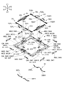
- FIG. 2 is an exploded perspective view of the module drive device 100.
- module drive device 100 is a camera module drive device.
- X1 represents one direction of the X-axis that constitutes a three-dimensional orthogonal coordinate system
- X2 represents the other direction of the X-axis
- Y1 represents one direction of the Y-axis constituting the three-dimensional orthogonal coordinate system
- Y2 represents the other direction of the Y-axis
- Z1 represents one direction of the Z axis that constitutes the three-dimensional orthogonal coordinate system
- Z2 represents the other direction of the Z axis.
- the X1 side of the optical device 150 corresponds to the front side (front side) of the optical device 150
- the X2 side of the optical device 150 corresponds to the rear side (back side) of the optical device 150.
- the Y1 side of the optical device 150 corresponds to the left side of the optical device 150, and the Y2 side of the optical device 150 corresponds to the right side of the optical device 150.
- the Z1 side of the optical device 150 corresponds to the upper side (subject side) of the optical device 150, and the Z2 side of the optical device 150 corresponds to the lower side (imaging element side) of the optical device 150. The same applies to other members in other figures.
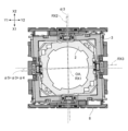
- the module drive device 100 that constitutes the optical device 150 includes a cover member 4 that is a part of the fixed side member FB.
- the cover member 4 is configured to function as a part of a housing HS that covers each member that constitutes the module drive device 100.
- the cover member 4 is made of non-magnetic metal.
- the cover member 4 may be made of magnetic metal.
- the cover member 4 has a box-like outer shape that defines a housing portion 4S.
- a camera module MD is housed in the housing section 4S.
- the cover member 4 includes a rectangular cylindrical outer peripheral wall 4A and a rectangular annular flat top plate that is provided so as to be continuous with the upper end (Z1 side end) of the outer peripheral wall 4A. It has a part 4B. A rectangular opening 4K is formed in the center of the top plate portion 4B.
- the outer peripheral wall portion 4A includes a first side plate portion 4A1 to a fourth side plate portion 4A4. The first side plate portion 4A1 and the third side plate portion 4A3 are opposed to each other, and the second side plate portion 4A2 and the fourth side plate portion 4A4 are opposed to each other.
- the first side plate portion 4A1 and the third side plate portion 4A3 extend perpendicularly to the second side plate portion 4A2 and the fourth side plate portion 4A4.
- the cover member 4 is bonded to the base member 8 with an adhesive.
- the adhesive is, for example, a photocurable adhesive.
- the photocurable adhesive is, for example, an ultraviolet curable adhesive or a visible light curable adhesive.
- the adhesive may be a thermosetting adhesive, a moisture curing adhesive, or the like. The same applies to the adhesive described below that joins one member to another member or adhesively fixes one member to another member.
- the base member 8 joined to the cover member 4 with an adhesive constitutes a housing HS together with the cover member 4.
- the camera module MD is an example of an optical module, and as shown in FIG. 2, includes a lens drive device LD, a lens body LS held by the lens drive device LD, and a substrate (flexible).
- the image sensor IS is fixed to a magnetic substrate FC).
- the spacer SP is fixed to the lens driving device LD, and the flexible substrate FC on which the image sensor IS is mounted is fixed to the spacer SP.
- a frame-shaped spacer SP is arranged between the lens drive device LD and the flexible substrate FC.
- the image sensor IS is housed in a space formed between the spacer SP and the flexible substrate FC, with its imaging surface exposed to the opening of the spacer SP.
- An IR cut filter may be arranged between the lens body LS and the image sensor IS. In this case, the IR cut filter may be attached to the upper surface of the frame of the spacer SP.
- the flexible substrate FC is a flexible substrate on which a wiring pattern for connecting the image sensor IS and a device outside the module drive device 100 is formed.
- the flexible substrate FC is a flexible printed circuit board configured to be repeatedly deformable.
- the image sensor IS may be mounted on a rigid substrate.
- the rigid board may be connected to the flexible board FC and connected to the outside via the flexible board FC. With this configuration, the flexible substrate FC can absorb the movement of the rigid substrate.
- the camera module MD is a camera module equipped with a shape memory alloy wire type module-side drive section DMx (see FIG. 24).
- the camera module MD may be a camera module including a drive unit of another type such as a voice coil motor type including a magnet and a coil or a piezoelectric type.
- the module-side drive unit DMx of the camera module MD is configured to move the lens body LS along the Z-axis direction, which is the optical axis direction of the lens body LS, on the Z1 side of the image sensor IS. It is configured. By moving the lens body LS in this manner, the camera module MD can realize an automatic focus adjustment function, which is one of the lens adjustment functions. Specifically, the camera module MD moves the lens body LS in a direction away from the image sensor IS to enable macro photography, and moves the lens body LS in a direction toward the image sensor IS to enable infinity photography. do.
- the camera module MD may be configured to be able to move the lens body LS in at least one of the X-axis direction and the Y-axis direction. By moving the lens body LS in this manner, the camera module MD may realize an image stabilization function, which is another one of the lens adjustment functions.
- FIG. 1 shows the states of the lens body LS and the lens driving device LD when the camera module MD is in a neutral state (neutral position).
- the neutral state of the camera module MD is when the lens body LS is located in the middle of the movable range in the Z-axis direction. means the state of being Typically, in the neutral state of the camera module MD, the lens body LS is located at the center of the movable range in the Z-axis direction.
- the initial state of the camera module MD when power is not supplied to the module-side drive unit DMx may be a neutral state.
- the camera module MD may be a fixed focus camera module. That is, the lens body LS may be arranged so as to be immovable relative to the image sensor IS.
- the housing HS of the module driving device 100 accommodates a driving part DM, a module holder 2, a connecting member 3, a metal member 5, an upper conductive member UC, a lower conductive member LC, etc. has been done.
- the drive unit DM includes a shape memory alloy wire SA that is an example of a shape memory actuator.
- the shape memory alloy wire SA includes first wire SA1 to eighth wire SA8 having approximately the same length and approximately the same diameter.
- the drive unit DM can move the module holder 2 using contraction of the shape memory alloy wire SA.
- the shape memory alloy wire SA when one or more of the first wire SA1 to the eighth wire SA8 contracts, the module holder 2 moves, and this movement causes another one or more to be stretched (stretched). It is configured so that In the illustrated example, the first wire SA1 to the fourth wire SA4 are also referred to as the first shape memory alloy wire SC1, and the fifth wire SA5 to the eighth wire SA8 are also referred to as the second shape memory alloy wire SC2.
- the drive unit DM is configured to realize movement of the movable member MB in three degrees of freedom. Movement with three degrees of freedom includes rotation (rotation) around the first direction (Z-axis direction), which is the optical axis direction, and rotation (oscillation) around the second direction (X-axis direction) perpendicular to the first direction. ), and rotation (oscillation) around a third direction (Y-axis direction) perpendicular to the first and second directions.
- the first direction is a direction parallel to the first rotation axis RX1 that coincides with the optical axis OA of the lens body LS
- the second direction is a direction parallel to the second rotation axis RX2.
- the third direction is a direction parallel to the third rotation axis RX3.
- the axis of the second rotating shaft RX2 is orthogonal to the axis of the first rotating shaft RX1
- the axis of the third rotating shaft RX3 is orthogonal to the axis of the first rotating shaft RX1.
- the axis of the second rotation axis RX2 and the axis of the third rotation axis RX3 are in a twisted positional relationship and are orthogonal to each other when viewed along the axial direction of the first rotation axis RX1.
- the axis of the second rotation axis RX2 and the axis of the third rotation axis RX3 may be orthogonal on the same plane. That is, the first rotation axis RX1, the second rotation axis RX2, and the third rotation axis RX3 may be rotation axes orthogonal to each other.
- the optical axis direction includes the direction of the optical axis OA with respect to the lens body LS and the direction parallel to the optical axis OA.
- the second rotation axis RX2 is also called a first swing axis
- the third rotation axis RX3 is also called a second swing axis.
- the neutral state of the module drive device 100 is within the rotatable range of the module holder 2. It means a state located in the middle. Typically, in the neutral state of the module drive device 100, the module holder 2 is located at the center of the rotatable range around the first rotation axis RX1. The same applies to the case where the module holder 2 is swingable around the second rotation axis RX2 and the case where the module holder 2 is swingable around the third rotation axis RX3.
- the initial state of the module drive device 100 when power is not supplied to the drive unit DM may be a neutral state.
- the imaging surface of the image sensor IS receives light from the lens body LS arranged opposite to the image sensor IS. It is perpendicular to the axis OA.
- the central axis of the image sensor IS (imaging surface) coincides with the optical axis OA of the lens body.
- the imaging surface of the image sensor IS is a surface parallel to the upper surface of the image sensor IS, which is the object-side surface.
- the movable member MB is a member driven by the drive unit DM.
- the movable member MB includes a module holder 2 that can hold the camera module MD, and a connecting member 3 that is connected to the module holder 2 so that the module holder 2 can swing.
- Camera module MD may be included in movable member MB.
- the module holder 2 is configured to be able to hold a camera module MD having a lens body LS and an image sensor IS.
- the module holder 2 is formed by injection molding a synthetic resin such as liquid crystal polymer (LCP).
- LCP liquid crystal polymer
- the module holder 2 includes a rectangular cylindrical outer peripheral wall 2A and a rectangular annular wall that is continuous with the upper end (Z1 side end) of the outer peripheral wall 2A.
- the flange portion 2G includes a left front flange portion 2GFL formed at the front left corner of the module holder 2, a right front flange portion 2GFR formed at the front right corner of the module holder 2, a module It includes a left rear flange portion 2GBL formed at the left rear corner of the holder 2 and a right rear flange portion 2GBR formed at the right rear corner of the module holder 2.
- the engaging portion 2T is a portion configured to engage with a portion of the connecting member 3.
- the engaging part 2T includes a left engaging part 2TL (see FIG. 5) formed to protrude outward from the left side of the outer peripheral wall 2A, and a left engaging part 2TL (see FIG. 5) that is formed to protrude outward from the right side of the outer peripheral wall 2A.
- the right engaging portion 2TR is formed to protrude.
- the module holder 2 is configured to function as a cover member for the camera module MD.
- the lens drive device LD is configured to be bonded to the lower end of the outer peripheral wall 2A with an adhesive.
- the connecting member 3 is configured so that the module holder 2 can swing around a third rotation axis RX3 that intersects with the optical axis direction.
- the connecting member 3 is formed by injection molding a synthetic resin such as liquid crystal polymer (LCP).
- LCP liquid crystal polymer
- the connecting member 3 has a rectangular annular frame portion arranged to surround the rectangular opening 3K.
- the frame has four sides 3E (first side 3E1 to fourth side 3E4).
- the connecting member 3 has an engaging portion V configured to engage with a corresponding portion of another member.
- the engaging portion V is configured to engage with a first engaging portion V1 configured to engage with a portion of the module holder 2 and with a portion of the base member 8. It includes a second engaging portion V2.
- the first engagement portion V1 includes a first left engagement portion V1L formed at the center of the second side 3E2 and a first right engagement portion V1L formed at the center of the fourth side 3E4. Contains the joint V1R.
- the second engaging portion V2 includes a second front engaging portion V2F formed at the center of the first side 3E1 and a second rear engaging portion V2B formed at the center of the third side 3E3. ,including.
- the upper conductive member UC is a flexible conductive member that connects two members that move relative to each other above the movable member MB.
- the upper conductive member UC is made of a metal plate whose main material is, for example, a copper alloy, a titanium-copper alloy (titanium-copper), or a copper-nickel alloy (nickel-tin-copper).
- the upper conductive member UC includes a first conductive member 6 that connects the module holder 2 and the connecting member 3, and a second conductive member 7 that connects the connecting member 3 and the base member 8.
- the first conductive member 6 includes a left conductive member 6L and a right conductive member 6R.
- the second conductive member 7 includes a front conductive member 7F and a rear conductive member 7B.
- the front conductive member 7F includes a left front conductive member 7FL and a right front conductive member 7FR
- the rear conductive member 7B includes a left rear conductive member 7BL and a right rear conductive member 7BR.
- the lower conductive member LC is a flexible conductive member that connects two members that move relative to each other below the movable member MB, and is also referred to as the third conductive member 9.
- the third conductive member 9 is made of a metal plate whose main material is, for example, a copper alloy, a titanium-copper alloy (titanium-copper), or a copper-nickel alloy (nickel-tin-copper).
- the third conductive member 9 includes four conductive members (left front conductive member 9FL, right front conductive member 9FR, left rear conductive member 9BL, and right rear conductive member 9BR).
- the base member 8 is formed by injection molding using a synthetic resin such as liquid crystal polymer (LCP).
- LCP liquid crystal polymer
- the base member 8 has a substantially rectangular outline when viewed from above, and has an opening 8K in the center, as shown in FIG. Specifically, the base member 8 has four sides 8E (first side 8E1 to fourth side 8E4) arranged to surround the opening 8K.
- the base member 8 has an engaging portion 8T configured to engage with a corresponding portion of another member.
- the engaging portion 8T is a portion configured to engage with a portion of the connecting member 3.
- the engaging portion 8T includes a front engaging portion 8TF formed at the center of the first side 8E1, a rear engaging portion 8TB formed at the center of the third side 8E3, including.
- the metal member 5 is configured so that the end of the shape memory alloy wire SA is fixed.
- the metal members 5 include eight lower metal members 5F (first lower terminal plate 5F1 to eighth lower terminal plate 5F8) and eight upper metal members 5M (first upper terminal plate 5M1 to eighth upper terminal plate 5M8).
- first lower metal members 5F first lower terminal plate 5F1 to fourth lower terminal plate 5F4
- the eight lower metal members 5F are configured to be fixed to the module holder 2.
- the remaining four of the 5F are configured to be fixed to the base member 8.
- the eight upper metal members 5M are configured to be fixed to the connecting member 3.
- the shape memory alloy wire SA is arranged along the inner surface of the outer peripheral wall portion 4A of the cover member 4, and is configured so that the movable member MB can be moved relative to the fixed member FB.
- the shape memory alloy wire SA includes a first wire SA1 to an eighth wire SA8, as shown in FIG.
- the holding body 2 is configured to be movable.
- each of the first wire SA1 to the eighth wire SA8 has one end fixed to the lower metal member 5F by crimping, welding, etc., and the other end being crimped, welding, etc. is fixed to the upper metal member 5M.
- the first rotating body Q1 is a rotating body disposed between the module holding body 2 and the connecting member 3
- the second rotating body Q2 is a rotating body disposed between the connecting member 3 and the base member 8. It is.
- the first rotating body Q1 and the second rotating body Q2 are balls (spheres) made of a magnetic material (magnetic metal).
- the first rotating body Q1 and the second rotating body Q2 may be made of a non-magnetic material such as plastic, non-magnetic metal, or ceramic.
- the first rotating body Q1 and the second rotating body Q2 may have a shape other than a sphere, such as a cylindrical body.
- the first rotating body Q1 includes a first left rotating body Q1L and a first right rotating body Q1R, which are arranged to face each other across the optical axis OA in the Y-axis direction.
- a line connecting the center of the first left rotating body Q1L and the center of the first right rotating body Q1R constitutes the axis of the third rotation axis RX3.
- the second rotating body Q2 includes a second front rotating body Q2F and a second rear rotating body Q2B, which are arranged to face each other across the optical axis OA in the X-axis direction.
- a line connecting the center of the second front rotating body Q2F and the center of the second rear rotating body Q2B constitutes the axis of the second rotating shaft RX2.
- the first magnet MG1 and the second magnet MG2 are arranged so that the module holder 2 and the connecting member 3 can be attracted to each other with the first rotating body Q1 in between.
- the first magnet MG1 is attached to the upper surface side of the connecting member 3, and the second magnet MG2 is attached to the lower surface side of the module holder 2.
- the first magnet MG1 and the second magnet MG2 are rectangular parallelepiped permanent magnets, and are bipolarly magnetized in the Z-axis direction.
- the first magnet MG1 and the second magnet MG2 are arranged so that the S pole of the first magnet MG1 and the N pole of the second magnet MG2 face each other with the first rotating body Q1 in between in the Z-axis direction.
- the side is magnetized to the north pole, and the bottom side is magnetized to the south pole.
- the first magnet MG1 includes a first left magnet MG1L that is adhesively fixed to the upper side of the first left engaging portion V1L located at the center of the second side portion 3E2 of the connecting member 3; a first right side magnet MG1R that is adhesively fixed to the upper side of the first right side engaging part V1R located at the center of the fourth side part 3E4 of the first right side magnet MG1R.
- the second magnet MG2 includes a second left magnet MG2L that is adhesively fixed to the lower side of the left side engaging part 2TL on the left side of the outer peripheral wall 2A of the module holder 2, and a second left magnet MG2L that is adhesively fixed to the lower side of the left engaging part 2TL on the left side of the outer peripheral wall 2A of the module holder 2. It includes a second right side magnet MG2R that is adhesively fixed to the lower side of the right side engaging portion 2TR on the right side surface.
- the third magnet MG3 and the fourth magnet MG4 are arranged so that the connecting member 3 and the base member 8 can be attracted to each other with the second rotating body Q2 in between.
- the third magnet MG3 is attached to the upper surface side of the connecting member 3, and the fourth magnet MG4 is attached to the lower surface side of the base member 8.
- the third magnet MG3 and the fourth magnet MG4 are rectangular parallelepiped permanent magnets, and are bipolarly magnetized in the Z-axis direction.
- the third magnet MG3 and the fourth magnet MG4 are arranged so that the S pole of the third magnet MG3 and the N pole of the fourth magnet MG4 face each other across the second rotating body Q2 in the Z-axis direction.
- the side is magnetized to the north pole, and the bottom side is magnetized to the south pole.
- the third magnet MG3 includes a third front magnet MG3F that is adhesively fixed to the upper side of the second front engaging portion V2F located at the center of the first side portion 3E1 of the connecting member 3;
- a third rear magnet MG3B is adhesively fixed to the upper side of the second rear engaging portion V2B located at the center of the third side portion 3E3.
- the fourth magnet MG4 includes a fourth front magnet MG4F that is adhesively fixed to the lower side of the front engaging portion 8TF located at the center of the first side 8E1 of the base member 8, and a fourth front magnet MG4F that is adhesively fixed to the lower side of the front engaging portion 8TF located at the center of the first side 8E1 of the base member 8; It includes a fourth rear magnet MG4B that is adhesively fixed to the lower side of the rear engaging portion 8TB located in the center.
- FIG. 4 is a perspective view of the module holder 2 to which various members are attached.
- FIG. 5 is a diagram showing the top and bottom surfaces of the module holder 2.
- FIG. 6 is a perspective view of the connecting member 3 to which various members are attached.
- FIG. 7 is a diagram showing the top and bottom surfaces of the connecting member 3.
- FIG. 8 is a perspective view of the base member 8 to which various members are attached.
- FIG. 9 is a diagram showing the top and bottom surfaces of the base member 8. As shown in FIG.
- the third lower terminal plate 5F3 is fixed to the front surface of the side flange portion 2GFL
- the third lower terminal plate 5F3 is fixed to the rear surface of the left rear flange portion 2GBL (see FIG. 5) of the module holder 2
- the fourth lower terminal plate 5F4 is fixed to the front surface of the side flange portion 2GFL. It is fixed to the rear surface of the right rear flange portion 2GBR of the module holder 2.
- the first lower terminal plate 5F1 to the fourth lower terminal plate 5F4 attached to the module holder 2 constitute the first movable part MB1 together with the module holder 2.
- the first lower terminal plate 5F1 to the fourth lower terminal plate 5F4 are fixed to the flange portion 2G with adhesive.
- the left conductive member 6L includes an inner fixed portion 6IL fixed to the module holder 2, an outer fixed portion 6EL fixed to the connecting member 3, an inner fixed portion 6IL and an outer fixed portion 6EL. It has an elastic portion 6GL that connects the.
- the right conductive member 6R includes an inner fixed part 6IR fixed to the module holder 2, an outer fixed part 6ER fixed to the connecting member 3, and an elastic part 6GR connecting the inner fixed part 6IR and the outer fixed part 6ER. has.
- the inner fixed portion 6IR is placed on the upper end surface of the right pedestal portion 2DR formed on the right side surface of the outer peripheral wall portion 2A of the module holder 2, and is fixed to the right pedestal portion 2DR with adhesive.
- the inner fixed portion 6IL is placed on the upper end surface of the left pedestal portion 2DL (see FIG. 5) formed on the left side surface of the outer peripheral wall portion 2A of the module holder 2, and is fixed to the left pedestal portion 2DL with adhesive. There is.
- the left front conductive member 9FL includes an inner fixed portion 9IFL fixed to the module holder 2, an outer fixed portion 9EFL fixed to the base member 8, an inner fixed portion 9IFL and an outer fixed portion 9EFL. It has an elastic portion 9GFL that connects the.
- the right front conductive member 9FR includes an inner fixed portion 9IFR fixed to the module holder 2, an outer fixed portion 9EFR fixed to the base member 8, and an elastic portion 9GFR connecting the inner fixed portion 9IFR and the outer fixed portion 9EFR. , has.
- the left rear conductive member 9BL includes an inner fixed part 9IBL fixed to the module holder 2, an outer fixed part 9EBL fixed to the base member 8, and an elastic part 9GBL connecting the inner fixed part 9IBL and the outer fixed part 9EBL. and has.
- the right rear conductive member 9BR includes an inner fixed portion 9IBR fixed to the module holder 2, an outer fixed portion 9EBR fixed to the base member 8, and an elastic portion 9GBR connecting the inner fixed portion 9IBR and the outer fixed portion 9EBR. and has.
- the inner fixed portion 9IFL is fixed to the lower surface of the left front flange portion 2GFL with an adhesive
- the inner fixed portion 9IFR is fixed to the lower surface of the right front flange portion 2GFR with an adhesive
- the inner fixed portion 9IBL is fixed to the lower surface of the right front flange portion 2GFR with an adhesive
- the inner fixed portion 9IBR is fixed to the lower surface of the right rear flange portion 2GBR with an adhesive.
- a first groove G1 for receiving the first rotating body Q1 is formed on the upper end surface of the engaging portion 2T of the module holder 2.
- the first groove G1 is an arcuate groove configured to extend along the circumference of a circle centered on the optical axis OA.
- the first groove portion G1 includes a first left groove portion G1L formed on the upper surface of the left side engaging portion 2TL, and a first groove portion G1L formed on the upper surface of the right side engaging portion 2TR. It includes the right groove portion G1R.
- the first left groove G1L is formed to receive the first left rotating body Q1L
- the first right groove G1R is formed to receive the first right rotating body Q1R.
- a broken line indicates an annular region sandwiched between two concentric circles centered on the optical axis OA, and each of the first left groove portion G1L and the first right groove portion G1R is a part of the annular region. represents.
- the first groove G1 is configured such that the module holder 2 and the connecting member 3, which are connected via the first rotating body Q1, can rotate relative to each other around the optical axis OA. ing.
- a second accommodating portion N2 for receiving the second magnet MG2 is formed on the lower end surface of the engaging portion 2T of the module holder 2.
- the second accommodating portion N2 is a rectangular parallelepiped-shaped recess configured to extend along the side surface of the outer peripheral wall portion 2A.
- the second accommodating part N2 includes a second left accommodating part N2L formed on the lower surface of the left engaging part 2TL, and a second accommodating part N2L formed on the lower surface of the right engaging part 2TR. It includes a second right housing part N2R.
- the second left housing part N2L is formed to receive the second left magnet MG2L
- the second right housing part N2R is formed to receive the second right magnet MG2R.
- the module holder 2 is configured such that the first buried current-carrying member 20 is embedded therein.
- the first embedded energizing member 20 is a member used for energizing the first shape memory alloy wire SC1 and the second shape memory alloy wire SC2, and is embedded in the module holder 2 by insert molding. More specifically, the first buried current-carrying member 20 includes four mutually independent members (back-side current-carrying member 20B, front-side current-carrying member 20F, left-side current-carrying member 20L, and right-side current-carrying member 20R).
- the third upper terminal plate 5M3 is fixed to the right side of the rear surface of the third side 3E3 of the connecting member 3
- the fourth upper terminal plate 5M4 is fixed to the right side of the rear side of the third side 3E3 of the connecting member 3. It is fixed on the left side of the rear of 3E3.
- the fifth upper terminal plate 5M5 is fixed to the rear side of the left side of the second side 3E2 of the connecting member 3
- the sixth upper terminal plate 5M6 is fixed to the front side of the left side of the second side 3E2 of the connecting member 3.
- the seventh upper terminal plate 5M7 is fixed to the front side of the right side of the fourth side 3E4 of the connecting member 3
- the eighth upper terminal plate 5M8 is fixed to the front side of the right side of the fourth side 3E4 of the connecting member 3.
- the first upper terminal plate 5M1 to the eighth upper terminal plate 5M8 attached to the connecting member 3 constitute the second movable part MB2 together with the connecting member 3.
- the first upper terminal plate 5M1 to the eighth upper terminal plate 5M8 are fixed to the connecting member 3 with adhesive.
- the outer fixed portion 6ER of the right conductive member 6R is placed on the upper end surface of the right pedestal portion 3DR formed at the center of the fourth side portion 3E4 of the connecting member 3, and is placed on the right side with adhesive. It is fixed to the pedestal part 3DR.
- the outer fixed portion 6EL of the left conductive member 6L is placed on the upper end surface of the left pedestal portion 3DL formed at the center of the second side portion 3E2 of the connecting member 3, and is fixed to the left pedestal portion 3DL with adhesive. There is.
- the left front conductive member 7FL includes an inner fixed portion 7IFL fixed to the connecting member 3, an outer fixed portion 7EFL fixed to the base member 8, an inner fixed portion 7IFL, and an outer fixed portion 7EFL. It has an elastic portion 7GFL that connects the.
- the right front conductive member 7FR includes an inner fixed portion 7IFR fixed to the connecting member 3, an outer fixed portion 7EFR fixed to the base member 8, and an elastic portion 7GFR connecting the inner fixed portion 7IFR and the outer fixed portion 7EFR. has.
- the left rear conductive member 7BL includes an inner fixed part 7IBL fixed to the connecting member 3, an outer fixed part 7EBL fixed to the base member 8, and an elastic part 7GBL connecting the inner fixed part 7IBL and the outer fixed part 7EBL.
- the right rear conductive member 7BR includes an inner fixed portion 7IBR fixed to the connecting member 3, an outer fixed portion 7EBR fixed to the base member 8, and an elastic portion 7GBR connecting the inner fixed portion 7IBR and the outer fixed portion 7EBR. , has.
- the inner fixed portion 7IFL and the inner fixed portion 7IFR are placed on the upper end surface of the front pedestal portion 3DF formed at the center of the first side portion 3E1 of the connecting member 3, and are attached to the front pedestal portion with adhesive. Fixed to 3DF.
- the inner fixed portion 7IBL and the inner fixed portion 7IBR are placed on the upper end surface of the rear pedestal portion 3DB formed at the center of the third side portion 3E3 of the connecting member 3, and fixed to the rear pedestal portion 3DB with adhesive. has been done.
- a first recess H1 for holding the first rotating body Q1 is formed in the lower end surface of the first engaging portion V1 of the connecting member 3.
- the first recess H1 is a recess configured to regulate (maintain) the position of the first rotating body Q1, that is, so that the first rotating body Q1 slides and rotates at that position without rolling.
- the first recess H1 is formed in the first left recess H1L formed in the lower surface of the first left engaging part V1L and in the lower surface of the first right engaging part V1R. It includes a first right side recess H1R.
- the first left recess H1L is formed to receive the first left rotating body Q1L
- the first right recess H1R is formed to receive the first right rotating body Q1R.
- the first recess H1 has an optical axis OA on a straight line connecting the center of the first left rotor Q1L held in the first left recess H1L and the center of the first right rotor Q1R held in the first right recess H1R. is configured so that it is located.
- the circumferential length of the first recess H1 is configured to be shorter than the circumferential length of the first groove G1.
- the first recess H1 does not need to have an arcuate shape centered on the optical axis OA in a plan view (bottom view), but a straight line in the tangential direction of a circle centered on the optical axis OA as shown in FIG. It may have any shape, such as a shape extending to .
- a second recess H2 for holding the second rotating body Q2 is formed on the lower end surface of the second engaging portion V2 of the connecting member 3.
- the second recess H2 is a recess configured to regulate (maintain) the position of the second rotating body Q2, that is, so that the second rotating body Q2 slides and rotates at that position without rolling.
- the second recess H2 is formed in the second front recess H2F formed in the lower surface of the second front engaging part V2F and in the lower surface of the second rear engaging part V2B. It includes a second rear recess H2B formed therein.
- the second front recess H2F is formed to receive the second front rotating body Q2F
- the second rear recess H2B is formed to receive the second rear rotating body Q2B.
- the second recess H2 allows light to be projected onto a straight line connecting the center of the second rear rotating body Q2B held in the second rear recess H2B and the center of the second front rotating body Q2F held in the second front recess H2F. It is configured such that the axis OA is located therein.
- the circumferential length of the second recess H2 is configured to be shorter than the circumferential length of the second groove G2.
- the second recess H2 does not need to have an arc shape centered on the optical axis OA in a plan view (bottom view), but a straight line in the tangential direction of a circle centered on the optical axis OA as shown in FIG. It may have any shape, such as a shape extending to .
- a first accommodating portion N1 for receiving the first magnet MG1 is formed on the upper end surface of the first engaging portion V1 of the connecting member 3.
- the first accommodating portion N1 is a rectangular parallelepiped-shaped recess configured to extend along the side portion 3E.
- the first accommodating part N1 includes a first left accommodating part N1L formed on the upper surface of the first left engaging part V1L, and an upper surface of the first right engaging part V1R.
- the first right housing portion N1R is formed in the first right housing portion N1R.
- the first left accommodating portion N1L is formed to receive the first left magnet MG1L
- the first right accommodating portion N1R is formed to receive the first right magnet MG1R.
- a third accommodating portion N3 for receiving a third magnet MG3 is formed on the upper end surface of the second engaging portion V2 of the connecting member 3.
- the third accommodating portion N3 is a rectangular parallelepiped-shaped recess configured to extend along the side portion 3E.
- the third accommodating part N3 includes a third front accommodating part N3F formed on the upper surface of the second front engaging part V2F and a second rear engaging part V2B. It includes a third rear housing part N3B formed on the top surface.
- the third front housing part N3F is formed to receive the third front magnet MG3F
- the third rear housing part N3B is formed to receive the third rear magnet MG3B.
- the connecting member 3 is configured such that the second buried current-carrying member 30 is embedded therein.
- the second embedded energizing member 30 is a member used for energizing the first shape memory alloy wire SC1, and is embedded in the connecting member 3 by insert molding. More specifically, the second buried energizing member 30 includes four mutually independent members (a left rear energizing member 30BL, a right rear energizing member 30BR, a left front energizing member 30FL, and a right front energizing member 30FR). .
- the seventh lower terminal plate 5F7 is fixed to the rear side of the left side of the second side 8E2, and the seventh lower terminal plate 5F7 is fixed to the rear side of the right side of the fourth side 8E4 of the base member 8. , is fixed to the front side of the right side of the fourth side portion 8E4 of the base member 8.
- the fifth lower terminal plate 5F5 to the eighth lower terminal plate 5F8 are fixed to the base member 8 with an adhesive.
- the outer fixed portion 7EFL of the left front conductive member 7FL and the outer fixed portion 7EFR of the right front conductive member 7FR are connected to the front pedestal portion 8DF formed at the center of the first side portion 8E1 of the base member 8. It is placed on the upper end surface of and fixed to the front pedestal part 8DF with adhesive.
- the outer fixed portion 7EBL of the left rear conductive member 7BL and the outer fixed portion 7EBR of the right rear conductive member 7BR are attached to the upper end surface of the rear pedestal portion 8DB formed at the center of the third side portion 8E3 of the base member 8. It is placed and fixed to the rear pedestal part 8DB with adhesive.
- the outer fixed portion 9EFL of the left front conductive member 9FL is placed on the upper end surface of the left front pedestal portion 8DFL formed at the center of the second side portion 8E2 of the base member 8. , is fixed to the left front pedestal part 8DFL with adhesive.
- the outer fixed portion 9EBL of the left rear conductive member 9BL is placed on the upper end surface of the left rear pedestal 8DBL formed at the center of the second side 8E2 of the base member 8, and is attached to the left rear pedestal with adhesive. It is fixed to section 8DBL.
- the outer fixed portion 9EFR of the right front conductive member 9FR is placed on the upper end surface of the right front pedestal portion 8DFR formed at the center of the fourth side portion 8E4 of the base member 8, and is attached to the right front pedestal portion 8DFR with adhesive. Fixed.
- the outer fixed portion 9EBR of the right rear conductive member 9BR is placed on the upper end surface of the right rear pedestal portion 8DBR formed at the center of the fourth side portion 8E4 of the base member 8, and is attached to the right rear pedestal with adhesive. It is fixed to part 8DBR.
- a second groove G2 for receiving the second rotating body Q2 is formed in the upper end surface of the engaging portion 8T of the base member 8.
- the second groove G2 is an arcuate groove configured to extend along the circumference of a circle centered on the optical axis OA.
- the second groove portion G2 is a second front groove portion G2F formed on the upper surface of the front side engaging portion 8TF, and a second groove portion G2F formed on the upper surface of the rear side engaging portion 8TB. It includes a second rear groove portion G2B.
- the second front groove G2F is formed to receive the second front rotating body Q2F
- the second rear groove G2B is formed to receive the second rear rotating body Q2B.
- a broken line indicates an annular region sandwiched between two concentric circles centered on the optical axis OA, and each of the second front groove portion G2F and the second rear groove portion G2B is a part of the annular region. represents something.
- the second groove G2 is configured such that the connecting member 3 and the base member 8, which are connected via the second rotating body Q2, can rotate relative to each other around the optical axis OA. There is.
- a fourth accommodating portion N4 for receiving the fourth magnet MG4 is formed on the lower end surface of the engaging portion 8T of the base member 8.
- the fourth accommodating portion N4 is a rectangular parallelepiped-shaped recess configured to extend along the side portion 8E.
- the fourth accommodating portion N4 includes a fourth front accommodating portion N4F formed on the lower surface of the front engaging portion 8TF and a lower surface of the rear engaging portion 8TB. It includes a fourth rear housing part N4B.
- the fourth front housing part N4F is formed to receive the fourth front magnet MG4F
- the fourth rear housing part N4B is formed to receive the fourth rear magnet MG4B.
- the base member 8 is configured such that a third buried current-carrying member 80 is embedded therein.
- the third embedded energizing member 80 is a member used for energizing the first shape memory alloy wire SC1 and the second shape memory alloy wire SC2, and is embedded in the base member 8 by insert molding. More specifically, the third buried current-carrying member 80 includes 22 mutually independent members (first current-carrying member CB1 to twenty-second current-carrying member CB22).
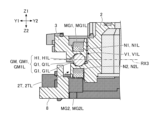
- FIG. 10 is a top view of the module holder 2, the connecting member 3, and the base member 8 combined with each other
- FIGS. 11 and 12 are a top view of the module holder 2, the connecting member 3, and the base member 8 combined with each other.
- 8 is a sectional view of FIG.
- FIG. 11 shows a cross section of the module holder 2, the connecting member 3, and the base member 8 in a plane parallel to the YZ plane including the cutting line CTL1 shown in FIG.
- a coarse dot pattern is applied to the module holder 2
- a fine dot pattern is applied to the connecting member 3
- an even finer dot pattern is applied to the base member 8.
- a fine cross pattern is attached to the north pole portion of the magnet
- a coarse cross pattern is attached to the south pole portion of the magnet.
- the guide mechanism GM is a mechanism that guides the rotation of the module holder 2 around the optical axis OA.
- the guide mechanism GM includes a first guide mechanism GM1 that guides the rotation of the module holder 2 around the optical axis OA with respect to the connecting member 3, and a connecting member 3 with respect to the base member 8 (which is connected to the connecting member 3). and a second guide mechanism GM2 that guides the rotation of the module holder 2 (including the module holder 2) around the optical axis OA.
- the first guide mechanism GM1 is, as shown in FIG. It is configured to include a first recessed portion H1 and a first rotating body Q1.
- the first guide mechanism GM1 includes a first left guide mechanism GM1L and a first right guide mechanism GM1R.
- the first left guide mechanism GM1L includes a first left groove G1L formed on the upper end surface of the left engaging portion 2TL, a first left recess H1L formed on the lower end surface of the first left engaging portion V1L, and It is configured to include a first left rotating body Q1L.
- the first right guide mechanism GM1R includes a first right groove portion G1R formed on the upper end surface of the right side engaging portion 2TR, a first right recessed portion H1R formed on the lower end surface of the first right side engaging portion V1R, and a first right side groove portion G1R formed on the upper end surface of the right side engaging portion 2TR. It is configured to include a right rotating body Q1R.
- the first left rotating body Q1L has an upper portion received in the first left recess H1L and a lower portion received in the first left groove G1L.
- the first left rotating body Q1L is arranged in the first left groove G1L so as to be able to roll within the first left groove G1L along the circumference of a circle centered on the optical axis OA, and It is arranged in the first left recess H1L so as to slide and rotate (not roll) within the first left recess H1L. Therefore, the first left guide mechanism GM1L can guide the rotation of the module holder 2 about the first rotation axis RX1 (optical axis OA) with respect to the connecting member 3. The same applies to the first right guide mechanism GM1R.
- the S pole part of the first left magnet MG1L is housed in the first left housing part N1L formed on the upper surface of the first left engaging part V1L, and the second left housing is formed on the lower surface of the left engaging part 2TL.
- the N-pole portion of the second left side magnet MG2L housed in the portion N2L is arranged to face the first left side rotating body Q1L.
- the first guide mechanism GM1 can maintain the state in which the module holder 2 and the connecting member 3 are attracted to each other even while the module holder 2 is rotating with respect to the connecting member 3, and the module holder 2 and the connecting member 3 can maintain a state in which they are attracted to each other. It is possible to suppress or prevent the connecting members 3 from separating from each other. Therefore, the first guide mechanism GM1 can suppress or prevent the module holder 2 from being erroneously tilted with respect to the connecting member 3.
- the second guide mechanism GM2 includes a second groove G2 formed on the upper end surface of the engaging portion 8T of the base member 8 and a lower end surface of the second engaging portion V2 of the connecting member 3. It is configured to include a second recess H2 and a second rotating body Q2. Specifically, the second guide mechanism GM2 includes a second front guide mechanism GM2F and a second rear guide mechanism GM2B.
- the second front guide mechanism GM2F includes a second front groove portion G2F formed on the upper end surface of the front engaging portion 8TF, a second front recess H2F formed on the lower end surface of the second front engaging portion V2F, and
- the second rear guide mechanism GM2B includes a second front rotary body Q2F, a second rear groove part G2B formed on the upper end surface of the rear engaging part 8TB, and a second rear engaging part V2B. It is configured to include a second rear side recess H2B formed in the lower end surface of and a second rear rotating body Q2B.
- the second rear rotating body Q2B has an upper portion received in the second rear recess H2B and a lower portion received in the second rear groove G2B. It is being In the illustrated example, the second rear rotating body Q2B is arranged in the second rear groove G2B so that it can roll within the second rear groove G2B along the circumference of a circle centered on the optical axis OA. , and is arranged in the second rear recess H2B so as to slide and rotate (not roll) within the second rear recess H2B.
- the second rear guide mechanism GM2B can guide the rotation of the connecting member 3 (including the module holder 2) with respect to the base member 8 around the first rotation axis RX1 (optical axis OA).
- the N-pole portion of the fourth rear magnet MG4B housed in the fourth rear housing portion N4B is arranged to face the second rear rotating body Q2B.
- the second guide mechanism GM2 maintains the state in which the base member 8 and the connecting member 3 are attracted to each other even while the connecting member 3 (including the module holder 2) is rotating with respect to the base member 8. Therefore, it is possible to suppress or prevent the base member 8 and the connecting member 3 from separating from each other. Therefore, the second guide mechanism GM2 can suppress or prevent the connection member 3 (including the module holder 2) from being erroneously tilted with respect to the base member 8.
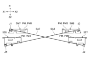
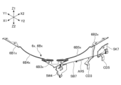
- FIG. 13 shows the seventh wire SA7 attached to each of the seventh upper terminal plate 5M7 and the seventh lower terminal plate 5F7, and the seventh wire SA7 attached to each of the eighth upper terminal plate 5M8 and the eighth lower terminal plate 5F8.
- 8 is a diagram when the eighth wire SA8 is viewed from the Y2 side (right side).
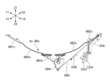
- FIG. 14 shows the seventh wire SA7 attached to each of the seventh upper terminal plate 5M7 and the seventh lower terminal plate 5F7, and the seventh wire SA7 attached to each of the eighth upper terminal plate 5M8 and the eighth lower terminal plate 5F8.
- FIG. 3 is a diagram of the eighth wire SA8 viewed from the X1 side (front side).
- the positional relationship of each member shown in FIGS. 13 and 14 corresponds to the positional relationship when the module drive device 100 is assembled. In FIGS. 13 and 14, illustration of other members is omitted for clarity.
- the following description with reference to FIGS. 13 and 14 relates to the combination of the seventh wire SA7 and the eighth wire SA8, but the combination of the first wire SA1 and the second wire SA2, the combination of the third wire SA3 and the fourth wire SA4 , and the combination of the fifth wire SA5 and the sixth wire SA6.
- one end of the seventh wire SA7 is fixed to the seventh upper terminal plate 5M7 at the holding portion J1 of the seventh upper terminal plate 5M7, and the other end of the seventh wire SA7 is fixed to the seventh lower terminal plate 5M7. It is fixed to the seventh lower terminal plate 5F7 at the holding portion J2 of 5F7.
- One end of the eighth wire SA8 is fixed to the eighth upper terminal plate 5M8 at the holding part J3 of the eighth upper terminal plate 5M8, and the other end of the eighth wire SA8 is fixed to the holding part J4 of the eighth lower terminal plate 5F8. It is fixed to the eighth lower terminal plate 5F8 at .
- the holding portion J1 is formed by bending a part of the seventh upper terminal plate 5M7. Specifically, a portion of the seventh upper terminal plate 5M7 forms the holding portion J1 by being bent while sandwiching the end (one end) of the seventh wire SA7. The end (one end) of the seventh wire SA7 is fixed to the holding part J1 by welding. The same applies to holding portions J2 to J4.
- the plate-like parts PM of the plurality of metal members 5 are arranged parallel to each other.
- the plate portion PM1 of the seventh upper terminal plate 5M7, the plate portion PM2 of the seventh lower terminal plate 5F7, the plate portion PM3 of the eighth upper terminal plate 5M8, and the eighth lower terminal plate are arranged parallel to each other along the XZ plane.
- the seventh wire SA7 and the eighth wire SA8 are arranged in a twisted positional relationship (so that they intersect three-dimensionally when viewed from the Y2 side). That is, the seventh wire SA7 and the eighth wire SA8 are arranged so as not to contact each other (become non-contact).
- one end of the seventh wire SA7 is at a higher position than the other end, as shown in FIG. 13, in a right side view from the Y2 side.
- the eighth wire SA8 is arranged so that one end thereof is higher than the other end, and the seventh wire SA7 and the eighth wire SA8 are arranged so as to intersect with each other.
- the first wire SA1 is arranged so that its one end is higher than the other end, and the second wire SA2 is arranged so that its one end is higher than the other end. Further, the first wire SA1 and the second wire SA2 are arranged to intersect with each other.
- the third wire SA3 is arranged so that its one end is higher than the other end
- the fourth wire SA4 is arranged so that its one end is higher than the other end. Further, the third wire SA3 and the fourth wire SA4 are arranged to intersect with each other.
- the fifth wire SA5 is arranged such that one end thereof is higher than the other end
- the sixth wire SA6 is arranged such that one end thereof is higher than the other end. Further, the fifth wire SA5 and the sixth wire SA6 are arranged to intersect with each other.
- the first wire SA1 to the eighth wire SA8 are all arranged so as to extend obliquely (non-parallel) to the X-axis and the Y-axis.
- the first wire SA1 and the second wire SA2 only need to be arranged so as to extend obliquely when viewed from the front, and do not need to intersect with each other when viewed from the front.
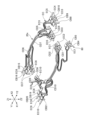
- FIG. 15 shows a metal member 5, a first electrically conductive member 6, a second electrically conductive member 7, a third electrically conductive member 9, a first buried electrically conductive member 20, a second embedded electrically conductive member 30, a third embedded electrically conductive member 80, and a shape memory It is a figure showing the positional relationship of alloy wire SA.
- FIG. 15 shows a metal member 5, a first conductive member 6, a second conductive member 7, a third conductive member 9, a first buried current carrying member 20, a second buried current carrying member 30, and a third buried current carrying member. 80 and a perspective view of the shape memory alloy wire SA.
- 16 to 19 are perspective views of a portion of the configuration shown in FIG. 15.
- FIG. 16 shows a state when the first current-carrying member CB1 of the third buried current-carrying member 80 is connected to a high potential, and the eighteenth current-carrying member CB18 of the third buried current-carrying member 80 is connected to a low potential.
- 17 shows the path of the current flowing through the first wire SA1
- FIG. 17 shows a state in which the second current-carrying member CB2 of the third buried current-carrying member 80 is connected to a high potential, and the eighteenth current-carrying member CB18 of the third buried current-carrying member 80 is connected to a high potential. shows the path of the current flowing through the second wire SA2 when it is connected to a low potential.
- FIG. 16 shows a state when the first current-carrying member CB1 of the third buried current-carrying member 80 is connected to a high potential, and the eighteenth current-carrying member CB18 of the third buried current-car
- FIG. 18 shows that when the eleventh current-carrying member CB11 of the third buried current-carrying member 80 is connected to a high potential and the sixth current-carrying member CB6 of the third buried current-carrying member 80 is connected to a low potential, the seventh wire SA7
- FIG. 19 shows the path of the current flowing through
- FIG. 19 shows that the third current-carrying member CB3 of the third buried current-carrying member 80 is connected to a high potential
- the sixth current-carrying member CB6 of the third buried current-carrying member 80 is connected to a low potential.
- 8 shows the path of the current flowing through the eighth wire SA8 when the current is applied.
- the current flows as indicated by the arrow AR1 in FIG.
- the current flows through the first wire SA1 as shown in FIG. Specifically, the current flows through the first energizing member CB1, the left front conductive member 7FL, the left front energizing member 30FL, the first upper terminal plate 5M1, the first wire SA1, the first lower terminal plate 5F1, and the front energizing member 20F. , and flows through the left front conductive member 9FL to the eighteenth current conducting member CB18.
- the current flows as indicated by the arrow AR2 in FIG.
- the current flows through the second wire SA2 as shown in FIG. Specifically, the current flows through the second energizing member CB2, the front right conductive member 7FR, the front right energizing member 30FR, the second upper terminal plate 5M2, the second wire SA2, the second lower terminal plate 5F2, and the front energizing member 20F. , and flows through the left front conductive member 9FL to the eighteenth current conducting member CB18.
- the path of the current flowing through the first wire SA1 and the path of the current flowing through the second wire SA2 partially overlap. Specifically, the two current paths overlap at the portions passing through the front current conducting member 20F, the left front conducting member 9FL, and the eighteenth current conducting member CB18. This configuration has the effect of reducing the number of parts.
- the current flows as indicated by the arrow AR3 in FIG.
- the current flows through the seventh wire SA7 as shown in FIG. Specifically, the current flows through the eleventh conductive member CB11, the seventh lower terminal plate 5F7, the seventh wire SA7, the seventh upper terminal plate 5M7, the right conductive member 6R, the right conductive member 20R, and the front right conductive member 9FR. and flows to the sixth current-carrying member CB6.
- the current flows as indicated by the arrow AR4 in FIG.
- the current flows through the eighth wire SA8 as shown in FIG. Specifically, the current flows through the third conductive member CB3, the eighth lower terminal plate 5F8, the eighth wire SA8, the eighth upper terminal plate 5M8, the right conductive member 6R, the right conductive member 20R, and the front right conductive member 9FR. and flows to the sixth current-carrying member CB6.
- the path of the current flowing through the seventh wire SA7 and the path of the current flowing through the eighth wire SA8 partially overlap. Specifically, the two current paths overlap at the portions passing through the right conductive member 6R, the right conductive member 20R, the front right conductive member 9FR, and the sixth conductive member CB6. This configuration has the effect of reducing the number of parts.
- FIGS. 15 to 19 members (metal member 5, first conductive member 6, second conductive member 7, third conductive member 9, first buried current conductive member 20) constituting the current conduction path of the shape memory alloy wire SA are shown.
- the second buried current-carrying member 30, and the third buried current-carrying member 80) two adjacent members are connected to each other. This connection is realized by welding or by conductive bonding material (conductive adhesive or solder).
- conductive bonding material conductive adhesive or solder
- the control device located outside the module drive device 100 controls the voltage applied to the third buried current-carrying member 80 connected to the first lower terminal plate 5F1 to the eighth lower terminal plate 5F8.
- the expansion and contraction of each of the wires SA1 to SA8 can be controlled.
- the control device controls the current supplied to each of the first wire SA1 to eighth wire SA8 via the third buried current-carrying member 80 connected to the first lower terminal plate 5F1 to the eighth lower terminal plate 5F8.
- the control device may be arranged within the module drive device 100.
- the control device may be a component of the module drive device 100.
- the control device rotates (rotates or rotates) the module holder 2 around at least one of the first rotation axis RX1, the second rotation axis RX2, and the third rotation axis RX3. (oscillation).
- the control device may realize an image stabilization function.
- FIG. 20 is a table showing the expansion and contraction states of the shape memory alloy wire SA when each of the three degrees of freedom of movement of the module holder 2 is realized. Specifically, “shrinkage” in FIG. 20 represents shrinking the shape memory alloy wire SA in the standard state, and “stretching” in FIG. 20 represents stretching the shape memory alloy wire SA in the standard state. .
- the reference state means the state of the shape memory alloy wire SA when the module drive device 100 is in a neutral state.
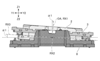
- FIG. 21 shows the three members (module holder 2, connecting member 3) when the module holder 2 and connecting member 3 rotate (swing) around the X axis (second rotation axis RX2) with respect to the base member 8. , and a front view of the base member 8).
- FIG. 22 is a right side view of the three members when the module holder 2 rotates (swings) around the Y-axis (third rotation axis RX3) with respect to the connecting member 3.
- FIGS. 21 to 23 is a top view of the three members when the module holder 2 and the connecting member 3 are rotated (rotated) around the Z axis (first rotation axis RX1) with respect to the base member 8.
- a coarse dot pattern is applied to the module holder 2
- a fine dot pattern is applied to the connecting member 3
- an even finer dot pattern is applied to the base member 8.
- FIG. 21 is a front view of the three members when the module holder 2 and the connecting member 3 swing clockwise by an angle ⁇ 1 around the X axis (second rotation axis RX2) with respect to the base member 8.
- the control device swings the module holder 2 and the connecting member 3 clockwise around the X axis (second rotation axis RX2) with respect to the base member 8 when viewed from the front, the control device operates as shown in the table of FIG. , the fifth wire SA5 and the sixth wire SA6 are expanded by approximately the same amount of expansion, and the seventh wire SA7 and the eighth wire SA8 are contracted by approximately the same amount of contraction.
- stretching the two shape memory alloy wires SA by approximately the same amount of stretching means stretching the two shape memory alloy wires SA until the lengths of the two shape memory alloy wires SA become approximately the same predetermined length. It means to cause.
- shrinking the two shape memory alloy wires SA by approximately the same amount of contraction means contracting the two shape memory alloy wires SA until the lengths of the two shape memory alloy wires SA become approximately the same predetermined length. do. The same applies to the following description.
- the control device maintains the amount of expansion and contraction of the first shape memory alloy wire SC1 (first wire SA1 to fourth wire SA4).
- control device adjusts the amount of expansion and contraction of each of the first wire SA1 to eighth wire SA8 by individually adjusting the magnitude of the current supplied to each of the first wire SA1 to eighth wire SA8. Control as described above. Under the control of this control device, the drive unit DM swings the module holder 2 and the connecting member 3 clockwise around the X axis (second rotation axis RX2) with respect to the base member 8, as shown in FIG. can be moved.
- the control device rotates the module holder 2 and the connecting member 3 counterclockwise around the X axis (second rotation axis RX2) with respect to the base member 8 when viewed from the front, the control device rotates the module holder 2 and the connecting member 3 as shown in the table of FIG. , the fifth wire SA5 and the sixth wire SA6 are contracted by approximately the same amount of contraction, and the seventh wire SA7 and the eighth wire SA8 are expanded by approximately the same amount of expansion.
- the control device maintains the amount of expansion and contraction of the first shape memory alloy wire SC1 (first wire SA1 to fourth wire SA4).
- the control device controls the amount of expansion and contraction of each of the first wire SA1 to eighth wire SA8 as described above by individually adjusting the magnitude of the current supplied to each of the first wire SA1 to eighth wire SA8. do.
- the drive unit DM can swing the module holder 2 and the connecting member 3 counterclockwise around the X axis (second rotation axis RX2) with respect to the base member 8.
- FIG. 22 is a right side view of the three members when the module holder 2 is swung by an angle ⁇ 2 counterclockwise around the Y-axis (third rotation axis RX3) with respect to the connecting member 3 and the base member 8. be.
- the control device swings the module holder 2 counterclockwise around the Y-axis (third rotation axis RX3) with respect to the connecting member 3 in a right side view, the control device
- the first wire SA1 and the second wire SA2 are expanded by approximately the same amount of expansion, and the third wire SA3 and the fourth wire SA4 are contracted by approximately the same amount of contraction.
- the control device maintains the amount of expansion and contraction of the second shape memory alloy wire SC2 (fifth wire SA5 to eighth wire SA8).
- control device adjusts the amount of expansion and contraction of each of the first wire SA1 to eighth wire SA8 by individually adjusting the magnitude of the current supplied to each of the first wire SA1 to eighth wire SA8. Control as described above. Under the control of this control device, the drive unit DM swings the module holder 2 counterclockwise around the Y axis (third rotation axis RX3) with respect to the connecting member 3, as shown in FIG. Can be done.
- the control device controls the first The wire SA1 and the second wire SA2 are contracted by approximately the same amount of contraction, and the third wire SA3 and the fourth wire SA4 are expanded by approximately the same amount of expansion.
- the control device maintains the amount of expansion and contraction of the second shape memory alloy wire SC2 (fifth wire SA5 to eighth wire SA8).
- the control device adjusts the amount of expansion and contraction of each of the first wire SA1 to eighth wire SA8 by individually adjusting the magnitude of the current supplied to each of the first wire SA1 to eighth wire SA8. Control as described above. Under the control of this control device, the drive unit DM can swing the module holder 2 clockwise around the Y-axis (third rotation axis RX3) with respect to the connecting member 3.
- FIG. 23 shows that the connecting member 3 rotates counterclockwise around the Z-axis (first rotation axis RX1) with respect to the base member 8 by an angle ⁇ 3, and that the connecting member 3 rotates with respect to the base member 8 around the Z-axis (first FIG. 7 is a top view of the three members when the module holder 2 is rotated by an angle ⁇ 4 around the rotation axis RX1). That is, FIG. 23 is a top view of the three members when the module holder 2 is rotated by an angle ⁇ 5 counterclockwise around the Z axis (first rotation axis RX1) with respect to the base member 8. Angle ⁇ 5 is the sum of angle ⁇ 3 and angle ⁇ 4.
- control device adjusts the amount of expansion and contraction of each of the first wire SA1 to eighth wire SA8 by individually adjusting the magnitude of the current supplied to each of the first wire SA1 to eighth wire SA8. Control as described above. Under the control of this control device, the drive unit DM rotates the connecting member 3 counterclockwise around the Z-axis (first rotation axis RX1) with respect to the base member 8, as shown in FIG. 23, and , the module holder 2 can be rotated counterclockwise around the Z axis (first rotation axis RX1) with respect to the connecting member 3.
- control device When the control device rotates the connecting member 3 clockwise around the Z-axis (first rotation axis RX1) with respect to the base member 8 in a top view, the control device rotates the fifth wire SA5 and The seventh wire SA7 is expanded by approximately the same amount of expansion, and the sixth wire SA6 and the eighth wire SA8 are contracted by approximately the same amount of contraction.
- the control device rotates the module holder 2 clockwise around the Z-axis (first rotation axis RX1) with respect to the connecting member 3 in a top view
- the control device rotates the first wire as shown in the table of FIG. SA1 and the third wire SA3 are contracted by approximately the same amount of contraction, and the second wire SA2 and the fourth wire SA4 are expanded by approximately the same amount of expansion.
- control device adjusts the amount of expansion and contraction of each of the first wire SA1 to eighth wire SA8 by individually adjusting the magnitude of the current supplied to each of the first wire SA1 to eighth wire SA8.
- the drive unit DM rotates the connecting member 3 clockwise around the Z-axis (first rotation axis RX1) with respect to the base member 8, and rotates the connecting member 3 around the Z-axis with respect to the connecting member 3.
- the module holder 2 can be rotated clockwise around the first rotation axis RX1.
- the table in FIG. 20 shows that when the connecting member 3 is rotated around the Z-axis (first rotation axis RX1) with respect to the base member 8 when viewed from above, the connecting member 3 is simultaneously rotated around the Z-axis (first rotation axis RX1) when viewed from above. 1 shows the expansion and contraction state of the shape memory alloy wire SA when the module holder 2 is rotated in the same direction around the rotation axis RX1).
- the control device maintains the Z axis (first rotation axis RX1) with respect to the base member 8 in a top view. ) may rotate only the connecting member 3.
- the control device maintains the amount of expansion and contraction of the second shape memory alloy wire SC2 (fifth wire SA5 to eighth wire SA8), thereby aligning the Z axis (first rotation axis RX1) with respect to the connecting member 3 in a top view. ) may rotate only the module holder 2.
- the control device rotates the connecting member 3 in one direction (for example, clockwise) around the Z-axis (first rotation axis RX1) with respect to the base member 8 when viewed from above, and at the same time rotates the connecting member 3 when viewed from above.
- the module holder 2 may be rotated in the other direction (for example, counterclockwise) around the Z axis (first rotation axis RX1).
- FIG. 24 is an exploded perspective view of the lens drive device LD.
- the lens driving device LD includes a lens holder 2x, a module-side metal member 5x, a leaf spring 6x, a module-side base member 8x, a module-side buried current-carrying member 20x, an image sensor holder AD, and an intermediate current-carrying member.
- EC and a module side shape memory alloy wire SB.
- the lens holder 2x is formed by injection molding synthetic resin such as liquid crystal polymer (LCP). Specifically, as shown in FIG. 24, the lens holder 2x includes a cylindrical portion 12x formed to extend along the optical axis OA, and a cylindrical portion 12x formed to protrude radially outward from the cylindrical portion 12x. The movable side pedestal part 2Dx and the protruding part 2Sx are included. In the example shown in FIG. 24, a spiral groove is formed on the inner peripheral surface of the cylindrical portion 12x so that the adhesive spreads between the upper half of the inner peripheral surface and the lens body LS (see FIG. 2). ing.
- LCP liquid crystal polymer
- the movable pedestal 2Dx includes a first movable pedestal 2D1x and a second movable pedestal 2D2x.
- the first movable pedestal 2D1x and the second movable pedestal 2D2x are arranged to extend in opposite directions (radially outward) with the optical axis OA in between.
- the protrusion 2Sx includes a first protrusion 2S1x and a second protrusion 2S2x.
- the first protruding portion 2S1x and the second protruding portion 2S2x are arranged so as to extend in opposite directions (radially outward) with the optical axis OA in between.
- the movable pedestal portion 2Dx and the protruding portions 2Sx are arranged so as to correspond to the four corners of the lens holder 2x, which has a substantially rectangular frame-like outer shape when viewed from above, and are arranged alternately. It is arranged like this. A portion of the leaf spring 6x is placed and fixed on each of the two movable pedestals 2Dx.
- the leaf spring 6x is configured to support the lens holder 2x movably in a direction parallel to the optical axis OA with respect to the module-side fixing member FBx (module-side base member 8x).
- the leaf spring 6x is made of a conductive metal plate whose main material is, for example, a copper alloy, a titanium-copper alloy (titanium-copper), or a copper-nickel alloy (nickel-tin-copper).
- the leaf spring 6x includes a first leaf spring 6Ax and a second leaf spring 6Bx.
- the module side base member 8x is formed by injection molding using synthetic resin such as liquid crystal polymer (LCP).
- LCP liquid crystal polymer
- the module-side base member 8x has a substantially rectangular frame-like outline when viewed from above, and has an opening 8Kx in the center.
- the module-side base member 8x has a rectangular annular base disposed so as to surround the circular opening 8Kx.
- the base has four sides 8Ex (first side 8E1x to fourth side 8E4x).
- the module-side base member 8x is integrated with the module holder 2 using an adhesive or the like, and together with the module holder 2 constitutes the casing of the camera module MD.
- the leaf spring 6x is configured to connect a movable pedestal 2Dx formed on the lens holder 2x and a fixed pedestal 8Dx formed on the module base member 8x.
- the fixed-side pedestal section 8Dx is a portion that projects upward from the base of the module-side base member 8x, and includes a first fixed-side pedestal section 8D1x and a second fixed-side pedestal section 8D2x.
- the first leaf spring 6Ax includes a first movable pedestal 2D1x formed on the lens holder 2x, a first fixed pedestal 8D1x and a second fixed pedestal 8D1x formed on the module side base member 8x. It is configured to be connected to each of the side pedestals 8D2x.
- the second plate spring 6Bx is connected to a second movable pedestal 2D2x formed on the lens holder 2x, and a first fixed pedestal 8D1x and a second fixed pedestal 8D2x formed on the module base member 8x, respectively. It is configured to connect.
- the module-side base member 8x is configured to function as a fixed-side wire support portion that supports one end of each of the eight module-side shape memory alloy wires SB.
- the lens holder 2x is configured to function as a movable wire support section that supports the other ends of the eight module-side shape memory alloy wires SB.
- the module-side base member 8x is configured such that a module-side embedded current-carrying member 20x formed from a conductive metal plate containing a material such as copper, iron, or an alloy having these as main components is embedded by insert molding. There is.
- the module-side buried current-carrying member 20x is a member used to power the third shape-memory alloy wire SC3 and the fourth shape-memory alloy wire SC4.
- the module-side buried current-carrying member 20x includes eleven mutually independent members (first current-carrying member CD1 to eleventh current-carrying member CD11).
- the image sensor holder AD is configured to hold the image sensor IS (see FIG. 2).
- the image sensor holder AD is fixed to the lower surface of the module-side base member 8x with an adhesive.
- a spacer SP (see FIG. 2) integrated with the image sensor IS is fixed to the image sensor holder AD.
- the image sensor holder AD constitutes a module-side fixing member FBx together with the module-side base member 8x.
- the module-side fixing member FBx may include a spacer SP.
- the intermediate current-carrying member EC is a member used for conducting current between the module-side buried current-carrying member 20x and the third buried current-carrying member 80 (see FIG. 8).
- the intermediate current-carrying member EC includes ten mutually independent members (first intermediate current-carrying member EC1 to tenth intermediate current-carrying member EC10). One end and the other end of each of the first intermediate current-carrying member EC1 to the tenth intermediate current-carrying member EC10 are connected by an elastically deformable connecting portion.
- the module-side metal member 5x is configured such that the end of the module-side shape memory alloy wire SB is fixed.
- the module-side metal member 5x is formed of non-magnetic metal and includes a module-side fixed metal member 5K and a module-side movable metal member 5W.
- the module-side fixed metal member 5K is configured to be adhesively fixed to the fixed-side pedestal portion 8Dx of the module-side base member 8x.
- the module-side movable metal member 5W is configured to be adhesively fixed to the movable-side pedestal portion 2Dx of the lens holder 2x.
- the module-side fixed metal member 5K is also referred to as a fixed-side terminal plate, and includes a first fixed-side terminal plate 5K1 to an eighth fixed-side terminal plate 5K8.
- the module-side movable metal member 5W is also referred to as a movable-side terminal plate, and includes a first movable-side terminal plate 5W1 to a fourth movable-side terminal plate 5W4.
- the first leaf spring 6Ax includes a first portion 6A1x fixed to the first fixed side pedestal portion 8D1x of the module side base member 8x, and a second portion fixed to the second fixed side pedestal portion 8D2x of the module side base member 8x. 6A2x, and a third portion 6A3x fixed to the first movable side pedestal portion 2D1x of the lens holder 2x.
- the first portion 6A1x is connected to the module-side buried current-carrying member 20x (eighth current-carrying member CD8) buried in the module-side base member 8x by laser welding or the like, and the third portion 6A3x is connected to the second movable side by soldering or the like. It is connected to each of the terminal plate 5W2 and the third movable side terminal plate 5W3.
- the second leaf spring 6Bx includes a first portion 6B1x fixed to the first fixed side pedestal portion 8D1x of the module side base member 8x, and a second portion fixed to the second fixed side pedestal portion 8D2x of the module side base member 8x. 6B2x, and a third portion 6B3x fixed to the second movable side pedestal 2D2x of the lens holder 2x.
- the second portion 6B2x is connected to the module-side buried current-carrying member 20x (third current-carrying member CD3) buried in the module-side base member 8x by laser welding or the like, and the third portion 6B3x is connected to the first movable side by soldering or the like. It is connected to each of the terminal plate 5W1 and the fourth movable side terminal plate 5W4.
- the module-side shape memory alloy wire SB is another example of a shape memory actuator, and like the shape memory alloy wire SA, its temperature rises when a current flows, and it contracts in accordance with the rise in temperature.
- the module-side shape memory alloy wire SB is arranged along the inner surface of the outer peripheral wall of the module holder 2, and the module-side movable member MBx cannot be moved with respect to the module-side fixed member FBx. It is configured so that it can be done. In the example shown in FIG.
- the module side shape memory alloy wire SB includes a first wire SB1 to an eighth wire SB8 having approximately the same length and approximately the same diameter, and includes a module side base member 8x as a module side fixing member FBx and a module side base member 8x as a module side fixing member FBx.
- the lens holder 2x which serves as a module-side movable member MBx, is configured to be movable with respect to the image sensor holder AD.
- each of the first wire SB1 to the eighth wire SB8 has one end fixed to the module side fixed metal member 5K by crimping or welding, and the other end movable on the module side by crimping or welding. It is fixed to the metal member 5W.
- the first wire SB1 to the fourth wire SB4 are also referred to as the third shape memory alloy wire SC3
- the fifth wire SB5 to the eighth wire SB8 are also referred to as the fourth shape memory alloy wire SC4.
- Each of the first fixed side terminal plate 5K1 to the eighth fixed side terminal plate 5K8 that fixes one end of each of the first wire SB1 to the eighth wire SB8 is connected to a module side buried energizer buried in the module side base member 8x. It is electrically connected to a corresponding conductive pattern formed on an external circuit board (not shown) via the member 20x, the intermediate current-carrying member EC, and the third buried current-carrying member 80.
- Each of the first movable terminal plate 5W1 to the fourth movable terminal plate 5W4 fixing the other ends of the first wire SB1 to the eighth wire SB8 is connected to a leaf spring 6x (the first leaf spring 6Ax and the second leaf spring 6Bx), electrically connected to the corresponding conductive pattern formed on the external circuit board via the module-side buried current-carrying member 20x buried in the module-side base member 8x, the intermediate current-carrying member EC, and the third buried current-carrying member 80. has been done. Therefore, the lens driving device LD is configured to be able to receive current flowing through each of the first wire SB1 to the eighth wire SB8 via the external circuit board.
- the module-side shape memory alloy wire SB constitutes the module-side drive section DMx.
- the module-side drive unit DMx can move the lens holder 2x with respect to the module-side base member 8x by utilizing the contraction of the module-side shape memory alloy wire SB.
- the module-side shape memory alloy wire SB is configured such that when one or more of the first wire SB1 to the eighth wire SB8 contracts, the lens holder 2x moves, and the other one or more is stretched by the movement. It is composed of
- one end (fixed end) of the first wire SB1 is at a higher position than the other end (movable end) in a front view from the X1 side.
- the second wire SB2 is arranged so that its one end (fixed end) is lower than the other end (movable end), and the first wire SB1 and second wire SB2 intersect. It is arranged like this.
- one end (fixed end) of each of the first wire SB1 and the second wire SB2 is located outside the other end (movable end) fixed to the first movable terminal plate 5W1. (X1 side) and is fixed to the module side fixed metal member 5K.
- the third wire SB3 is arranged so that its one end (fixed end) is higher than the other end (movable end), and the fourth wire SB4 is arranged so that its one end (fixed end) is higher than the other end (movable end). ) is arranged at a lower position than the other end (movable end), and furthermore, the third wire SB3 and the fourth wire SB4 are arranged to intersect. Further, in a top view, one end (fixed end) of each of the third wire SB3 and the fourth wire SB4 is located outside (X2 side) than the other end (movable end).
- the fifth wire SB5 is arranged so that its one end (fixed end) is lower than the other end (movable end), and the sixth wire SB6 is arranged so that its one end (fixed end) is lower than the other end (movable end).
- the fifth wire SB5 and the sixth wire SB6 are arranged so as to intersect with each other. Further, in a top view, one end (fixed end) of each of the fifth wire SB5 and the sixth wire SB6 is located on the outside (Y1 side) of the other end (movable end).
- the seventh wire SB7 is arranged so that its one end (fixed end) is at a lower position than the other end (movable end), and the eighth wire SB8 is arranged so that its one end (fixed end) is lower than the other end (movable end).
- the seventh wire SB7 and the eighth wire SB8 are arranged so as to intersect with each other. Further, in a top view, one end (fixed end) of each of the seventh wire SB7 and the eighth wire SB8 is located outside (Y2 side) than the other end (movable end).
- the first wire SB1 to the eighth wire SB8 are all arranged so as to extend obliquely (non-parallel) to the X-axis and the Y-axis.
- first wire SB1 and the second wire SB2 only need to be arranged so as to extend obliquely when viewed from the front, and do not need to intersect with each other when viewed from the front.
- the module-side drive unit DMx is, in principle, configured to be able to realize six degrees of freedom of movement of the module-side movable member MBx.
- the movements with six degrees of freedom include translation in the first direction (Z-axis direction) which is the optical axis direction, translation in the second direction (X-axis direction) perpendicular to the first direction (Z-axis direction), and translation in the first direction and the second direction (X-axis direction).
- the first direction is a direction parallel to the first rotation axis RX1 that coincides with the optical axis OA of the lens body LS
- the second direction is a direction parallel to the second rotation axis RX2.
- the third direction is a direction parallel to the third rotation axis RX3.
- the module side drive unit DMx is configured not to utilize rotation around the Z axis, rotation around the X axis, and rotation around the Y axis.
- the camera module MD can be rotated around the Z-axis by rotating (rotating) the module holder 2 around the Z-axis by the drive unit DM, and the lens holder 2x can also be rotated around the Z-axis. This is because there is no need to rotate it.
- the camera module MD can be rotated around the X-axis by rotating (swinging) the module holder 2 around the X-axis by the drive unit DM, and the lens holder 2x can also be rotated around the X-axis. This is because there is no need to rotate it.
- FIGS. 25 and 26 are diagrams showing the positional relationship among the module-side metal member 5x, the leaf spring 6x, the module-side buried current-carrying member 20x, and the module-side shape memory alloy wire SB.
- FIG. 25 is a perspective view of the module-side metal member 5x, leaf spring 6x, module-side buried current-carrying member 20x, and module-side shape memory alloy wire SB that are combined with each other
- FIG. It is a top view of module side movable metal member 5W and leaf spring 6x.
- the first leaf spring 6Ax which is one of the leaf springs 6x, has a first portion 6A1x fixed to the first fixed-side pedestal portion 8D1x (see FIG. 24) of the module-side base member 8x.
- the second portion 6A2x is fixed to the second fixed pedestal 8D2x (see FIG. 24) of the module side base member 8x, and the second portion 6A2x is fixed to the first movable pedestal 2D1x (see FIG. 24) of the lens holder 2x.
- a fourth portion 6A4x connects the first portion 6A1x and the third portion 6A3x
- a fifth portion 6A5x connects the second portion 6A2x and the third portion 6A3x.
- the second leaf spring 6Bx which is another one of the leaf springs 6x, is a first leaf spring fixed to the first fixed-side pedestal portion 8D1x (see FIG. 24) of the module-side base member 8x.
- the first portion 6A1x of the first leaf spring 6Ax includes a through hole through which an upwardly projecting cylindrical protrusion formed on the first fixed base portion 8D1x is inserted, and an upper end portion of the eighth current-carrying member CD8.
- a through hole used for bonding is formed.
- the first portion 6A1x and the first stationary pedestal portion 8D1x are fixed by hot caulking or cold caulking to the protrusion.
- the first portion 6Ax1 and the protrusion may be fixed with an adhesive.
- the first portion 6Ax1 and the eighth current-carrying member CD8 are joined by welding such as laser welding.
- the first portion 6Ax1 and the eighth current-carrying member CD8 may be joined by solder, a conductive adhesive, or the like. The same applies to the second portion 6B2x of the second leaf spring 6Bx.
- the third portion 6A3x of the first leaf spring 6Ax has a through hole through which a cylindrical protrusion formed on the first movable side pedestal portion 2D1x that protrudes upward is inserted, and a second movable side terminal plate 5W2 and a second movable side terminal plate 5W2. 3. Portions used for joining with each of the movable side terminal plates 5W3 are formed.
- the third portion 6A3x and the first movable base portion 2D1x are fixed to each other by hot caulking or cold caulking to the protruding portion.
- the third portion 6A3x and the first movable pedestal portion 2D1x may be fixed with an adhesive.
- the third portion 6A3x is joined to each of the second movable terminal plate 5W2 and the third movable terminal plate 5W3 by welding such as laser welding.
- welding such as laser welding
- the connection between the third portion 6A3x and each of the second movable terminal plate 5W2 and the third movable terminal plate 5W3 may be realized by solder, a conductive adhesive, or the like.
- solder a conductive adhesive, or the like.
- a through hole is formed in the second portion 6A2x of the first leaf spring 6Ax, into which a cylindrical protrusion formed on the second fixed side pedestal portion 8D2x and protruding upward is inserted.
- the second portion 6A2x and the second fixed side pedestal portion 8D2x are fixed by hot caulking or cold caulking to the protruding portion.
- the second portion 6A2x and the second fixed side pedestal portion 8D2x may be fixed with an adhesive. The same applies to the first portion 6B1x of the second leaf spring 6Bx.
- the leaf spring 6x is configured to have two-fold rotational symmetry with respect to the first rotation axis RX1. Therefore, the leaf spring 6x has almost no adverse effect on the weight balance of the lens holder 2x. The leaf spring 6x has almost no adverse effect on the weight balance of the module side movable member MBx supported by the eight module side shape memory alloy wires SB (first wire SB1 to eighth wire SB8).
- the module-side fixed metal members 5K (first fixed-side terminal plate 5K1 to eighth fixed-side terminal plate 5K8) are connected to an external circuit board (not shown) via the module-side buried current-carrying member 20x.
- the conductive pattern is configured to be electrically connected to a corresponding conductive pattern formed on the conductive pattern.
- the first fixed terminal plate 5K1 is connected to the first current-carrying member CD1
- the second fixed-side terminal plate 5K2 is connected to the second current-carrying member CD2
- the third fixed-side terminal plate 5K3 is connected to the sixth current-carrying member.
- the fourth fixed terminal plate 5K4 is connected to the seventh current-carrying member CD7
- the fifth fixed-side terminal plate 5K5 is connected to the tenth current-carrying member CD10
- the sixth fixed-side terminal plate 5K6 is connected to the ninth current-carrying member CD7.
- the seventh stationary terminal plate 5K7 is connected to the member CD9
- the seventh stationary terminal plate 5K7 is connected to the fifth current-carrying member CD5
- the eighth stationary terminal plate 5K8 is connected to the fourth current-carrying member CD4.
- the module-side movable metal member 5W and the leaf spring 6x are joined to each other.
- the first movable terminal plate 5W1 and the fourth movable terminal plate 5W4 are joined substantially perpendicularly to the third portion 6B3x of the second leaf spring 6Bx by welding such as laser welding. has been done.
- the second movable terminal plate 5W2 and the third movable terminal plate 5W3 are substantially perpendicularly joined to the third portion 6A3x of the first plate spring 6Ax by welding such as laser welding.
- the module-side fixed metal member 5K and the leaf spring 6x are not joined to each other.
- the first fixed terminal plate 5K1 and the second fixed terminal plate 5K2 are arranged apart from the first portion 6B1x of the second leaf spring 6Bx
- the fifth fixed terminal plate 5K5 and the second fixed terminal plate 5K2 are arranged apart from the first portion 6B1x of the second leaf spring 6Bx.
- the fixed side terminal plate 5K6 is spaced apart from the first portion 6A1x of the first leaf spring 6Ax.
- the third fixed side terminal plate 5K3 and the fourth fixed side terminal plate 5K4 are arranged apart from the second portion 6A2x of the first leaf spring 6Ax, and the seventh fixed side terminal plate 5K7 and the eighth fixed side terminal plate 5K8 is arranged apart from the second portion 6B2x of the second leaf spring 6Bx.
- FIGS. 27 and 28 are perspective views of a portion of the configuration shown in FIG. 25.
- a current flows through the seventh wire SB7 as shown by an arrow AR5 in FIG. 27.
- the current flows through the fifth current-carrying member CD5, the seventh fixed terminal plate 5K7, the seventh wire SB7, the fourth movable terminal plate 5W4, and the second leaf spring 6Bx (the third portion 6B3x, the fifth portion 6B5x and second portion 6B2x) and flows to the third current-carrying member CD3.
- a current flows through the eighth wire SB8 as shown by an arrow AR6 in FIG. 28.
- the current flows through the fourth current-carrying member CD4, the eighth fixed terminal plate 5K8, the eighth wire SB8, the fourth movable terminal plate 5W4, and the second leaf spring 6Bx (third portion 6B3x, fifth portion 6B5x and second portion 6B2x) and flows to the third current-carrying member CD3.
- the path of the current flowing through the seventh wire SB7 and the path of the current flowing through the eighth wire SB8 partially overlap.
- the two current paths connect the fourth movable terminal plate 5W4, the second leaf spring 6Bx (third portion 6B3x, fifth portion 6B5x, and second portion 6B2x), and third current-carrying member CD3.
- This configuration has the effect of reducing the number of parts.
- the control device can control the expansion and contraction of each of the first wire SB1 to eighth wire SB8 by controlling the voltage applied to each of the first fixed terminal plate 5K1 to the eighth fixed terminal plate 5K8.
- the control device controls the current supplied to each of the first wire SB1 to eighth wire SB8 via each of the first fixed terminal plate 5K1 to the eighth fixed terminal plate 5K8, thereby The expansion and contraction of each of the wires SB1 to 8th wire SB8 can be controlled.
- the control device may move the lens holder 2x in a direction intersecting the first direction (optical axis direction) by controlling the current flowing through the plurality of module-side shape memory alloy wires SB.
- the direction intersecting the first direction may be, for example, a second direction (X-axis direction) perpendicular to the first direction, or a third direction (Y-axis direction) perpendicular to each of the first direction and the second direction. It's okay.
- the control device may rotate the lens holder 2x around the Z axis, the X axis, or the Y axis. By such movement of the lens holder 2x, the control device may realize an image stabilization function.
- FIG. 29 is a table showing the expansion and contraction states of the module-side shape memory alloy wire SB when each of the six degrees of freedom of movement of the lens holder 2x is realized.
- shrinkage in FIG. 29 represents shrinking the module-side shape memory alloy wire SB in the standard state
- stretch in FIG. 29 represents stretching the module-side shape memory alloy wire SB in the standard state. It means to do something.
- the reference state means the state of the module-side shape memory alloy wire SB when the camera module MD (lens drive device LD) is in a neutral state. In the illustrated example, when the camera module MD (lens drive device LD) is in the neutral state, each of the first wire SB1 to the eighth wire SB8 is not slack because a current is flowing through them.
- the control device shrinks the first wire SB1 and the second wire SB2 relatively small, as shown in the table of FIG. the third wire SB3 and the fourth wire SB4 are stretched relatively small, the fifth wire SB5 and the sixth wire SB6 are contracted relatively large, and the seventh wire SB7 and the eighth wire SB8 are stretched relatively large.
- the respective shrinkage amounts of the first wire SB1 and the second wire SB2 are is smaller than the amount of contraction of each of the fifth wire SB5 and the sixth wire SB6.
- Stretching the third wire SB3 and the fourth wire SB4 to a relatively small amount and stretching the seventh wire SB7 and the eighth wire SB8 to a relatively large extent means that the amount of each of the third wire SB3 and the fourth wire SB4 is is smaller than the respective stretching amounts of the seventh wire SB7 and the eighth wire SB8.
- the control device causes the first wire SB1 and the second wire SB2 to contract relatively small by approximately the same amount of contraction, and to extend the third wire SB3 and the fourth wire SB4 relatively small by approximately the same amount of expansion,
- the fifth wire SB5 and the sixth wire SB6 are relatively greatly shrunk by approximately the same amount of contraction, and the seventh wire SB7 and the eighth wire SB8 are relatively greatly expanded by approximately the same amount of expansion. The same applies to the following description.
- the control device controls each of the first wire SB1 to eighth wire SB8 as described above by individually adjusting the magnitude of the current supplied to each of the first wire SB1 to eighth wire SB8. expand and contract.
- the module-side drive unit DMx can translate the lens holder 2x in the X1 direction (forward) with respect to the module-side base member 8x.
- the control device When translating the lens holder 2x in the X2 direction (rearward) with respect to the module side base member 8x, the control device stretches the first wire SB1 and the second wire SB2 relatively small as shown in the table of FIG. , the third wire SB3 and the fourth wire SB4 are contracted relatively small, the fifth wire SB5 and the sixth wire SB6 are stretched relatively large, and the seventh wire SB7 and the eighth wire SB8 are contracted relatively large.
- the module-side drive unit DMx can translate the lens holder 2x in the X2 direction (backward) with respect to the module-side base member 8x.
- the control device moves the first wire SB1 and the second wire SB2 relatively large, as shown in the table of FIG.
- the third wire SB3 and the fourth wire SB4 are stretched relatively large, the fifth wire SB5 and the sixth wire SB6 are contracted relatively small, and the seventh wire SB7 and the eighth wire SB8 are made relatively small. Stretch.
- the module-side drive unit DMx can translate the lens holder 2x in the Y1 direction (leftward) with respect to the module-side base member 8x.
- the control device moves the first wire SB1 and the second wire SB2 relatively large as shown in the table of FIG.
- the third wire SB3 and the fourth wire SB4 are stretched relatively large, the fifth wire SB5 and the sixth wire SB6 are stretched relatively small, and the seventh wire SB7 and the eighth wire SB8 are made relatively small. Shrink it.
- the module-side drive unit DMx can translate the lens holder 2x in the Y2 direction (rightward) with respect to the module-side base member 8x.
- the control device When the control device translates the lens holder 2x in the Z1 direction (upward) with respect to the module side base member 8x, as shown in the table of FIG. , and seventh wire SB7 are expanded by approximately the same amount of expansion, and the first wire SB1, third wire SB3, sixth wire SB6, and eighth wire SB8 are contracted by approximately the same amount of contraction.
- the module-side drive unit DMx can translate the lens holder 2x in the Z1 direction (upward) with respect to the module-side base member 8x.
- the control device When the control device translates the lens holder 2x in the Z2 direction (downward) with respect to the module-side base member 8x, as shown in the table of FIG. , and seventh wire SB7 are contracted by approximately the same amount of contraction, and the first wire SB1, third wire SB3, sixth wire SB6, and eighth wire SB8 are expanded by approximately the same amount of expansion.
- the module-side drive unit DMx can translate the lens holder 2x in the Z2 direction (downward) with respect to the module-side base member 8x.
- the control device controls the third The wire SB3, the fourth wire SB4, the sixth wire SB6, and the seventh wire SB7 are contracted by approximately the same amount of contraction, and the first wire SB1, the second wire SB2, the fifth wire SB5, and the eighth wire SB8 are Stretch by approximately the same amount.
- the module side drive unit DMx can rotate the lens holder 2x clockwise around the X axis (second rotation axis RX2) with respect to the module side base member 8x.
- the control device When rotating the lens holder 2x counterclockwise around the X axis (second rotation axis RX2) with respect to the module-side base member 8x when viewed from the front, the control device rotates the lens holder 2x as shown in the table of FIG.
- the three wires SB3, the fourth wire SB4, the sixth wire SB6, and the seventh wire SB7 are stretched by approximately the same amount, and the first wire SB1, the second wire SB2, the fifth wire SB5, and the eighth wire SB8 are stretched. are contracted by approximately the same amount of contraction.
- the module side drive unit DMx can rotate the lens holder 2x counterclockwise around the X axis (second rotation axis RX2) with respect to the module side base member 8x.
- the control device When rotating the lens holder 2x clockwise around the Y-axis (third rotation axis RX3) with respect to the module-side base member 8x in a right side view, the control device rotates the lens holder 2x as shown in the table of FIG.
- the first wire SB1, the fourth wire SB4, the seventh wire SB7, and the eighth wire SB8 are contracted by approximately the same amount of contraction, and the second wire SB2, the third wire SB3, the fifth wire SB5, and the sixth wire SB6 are Stretch by approximately the same amount.
- the module-side drive unit DMx can rotate the lens holder 2x clockwise around the Y-axis (third rotation axis RX3) with respect to the module-side base member 8x.
- the control device rotates the lens holder 2x counterclockwise around the Y axis (third rotation axis RX3) with respect to the module side base member 8x in a right side view, as shown in the table of FIG.
- the first wire SB1, the fourth wire SB4, the seventh wire SB7, and the eighth wire SB8 are stretched by substantially the same amount, and the second wire SB2, the third wire SB3, the fifth wire SB5, and the sixth wire SB6 is contracted by approximately the same amount of contraction.
- the module-side drive unit DMx can rotate the lens holder 2x counterclockwise around the Y-axis (third rotation axis RX3) with respect to the module-side base member 8x.
- the control device controls the first Wire SB1 to fourth wire SB4 are contracted by approximately the same amount of contraction, and fifth wire SB5 to eighth wire SB8 are expanded by approximately the same amount of expansion.
- the module-side drive unit DMx can rotate the lens holder 2x clockwise around the Z-axis (first rotation axis RX1) with respect to the module-side base member 8x.
- the control device When the control device rotates the lens holder 2x counterclockwise around the Z-axis (first rotation axis RX1) with respect to the module-side base member 8x in a top view, the control device The first wire SB1 to the fourth wire SB4 are expanded by approximately the same amount of expansion, and the fifth wire SB5 to the eighth wire SB8 are contracted by approximately the same amount of contraction.
- the module-side drive unit DMx can rotate the lens holder 2x counterclockwise around the Z-axis (first rotation axis RX1) with respect to the module-side base member 8x.
- FIG. 30 is a perspective view of the module-side buried current-carrying member 20x, the third buried current-carrying member 80, and the intermediate current-carrying member EC.
- FIG. 30 is a perspective view of the module-side buried current-carrying member 20x, the third buried current-carrying member 80, and the intermediate current-carrying member EC.
- the current-carrying members (first current-carrying member CB1 to third current-carrying member CB3, sixth current-carrying member CB6, third current-carrying member CB6, The illustrations of the seventh current-carrying member CB7, eleventh current-carrying member CB11 to fourteenth current-carrying member CB14, seventeenth current-carrying member CB17, eighteenth current-carrying member CB18, and twenty-second current conducting member CB22) are omitted.
- ten current-carrying members (first current-carrying member CD1 to tenth current-carrying member CD10) constituting the module-side buried current-carrying member 20x are connected to the third buried current-carrying member 80 via the intermediate current-carrying member EC. has been done.
- the first current-carrying member CD1 is connected to the fourth current-carrying member CB4 via the first intermediate current-carrying member EC1
- the second current-carrying member CD2 is connected to the fifth current-carrying member via the second intermediate current-carrying member EC2.
- CB5 the third current-carrying member CD3 is connected to the ninth current-carrying member CB9 via the fourth intermediate current-carrying member EC4
- the fourth current-carrying member CD4 is connected to the tenth current-carrying member via the fifth intermediate current-carrying member EC5.
- the fifth current-carrying member CD5 is connected to the eighth current-carrying member CB8 via the third intermediate current-carrying member EC3.
- the sixth current-carrying member CD6 is connected to the fifteenth current-carrying member CB15 via the sixth intermediate current-carrying member EC6, and the seventh current-carrying member CD7 is connected to the sixteenth current-carrying member CB16 via the seventh intermediate current-carrying member EC7.
- the eighth energizing member CD8 is connected to the 20th energizing member CB20 via the 9th intermediate energizing member EC9, and the 9th energizing member CD9 is connected to the 21st energizing member CB21 via the 10th intermediate energizing member EC10,
- the tenth current-carrying member CD10 is connected to the nineteenth current-carrying member CB19 via the eighth intermediate current-carrying member EC8.
- each of the first wire SB1 to the eighth wire SB8 is connected to a corresponding conductive pattern formed on the external circuit board via the module-side buried current-carrying member 20x, the intermediate current-carrying member EC, and the third buried current-carrying member 80. can be electrically connected to. Therefore, the lens driving device LD can receive current flowing through each of the first wire SB1 to the eighth wire SB8 via the external circuit board.
- the control device can realize six degrees of freedom of movement of the lens holder 2x. Specifically, the control device can realize each of the six degrees of freedom of movement by individually adjusting the current supplied to each of the first wire SB1 to the eighth wire SB8.
- the control device may realize the movement of the lens holder 2x by combining a plurality of movements of six degrees of freedom.
- the control device causes the corresponding module-side shape memory alloy wire SB to contract and move the lens holder 2x by applying a current to one or more of the first wire SB1 to the eighth wire SB8. let Then, the control device realizes the extension of the module-side shape memory alloy wire SB by elongating another one or more of the first wire SB1 to the eighth wire SB8 by the movement.
- the lens body LS can move in the X axis direction and the Y axis. If the lens body LS in the camera module MD held by the module holder 2 is movable along the Z-axis direction and the Z-axis direction, the lens body LS in the camera module MD held by the module holder 2 can realize movement with six degrees of freedom. That is, the combination of the drive unit DM in the module drive device 100 and the module-side drive unit DMx in the camera module MD can realize movement of the lens body LS with six degrees of freedom. Therefore, the module-side drive unit DMx may be configured not to utilize the three degrees of freedom of movement (rotation around the X-axis, rotation around the Y-axis, and rotation around the Z-axis).
- the movement of the movable member MB may be detected by a motion detection section (not shown).
- the motion detection section may be configured by, for example, a magnet attached to the movable member MB such as the module holder 2, and a magnetic sensor attached to the fixed member FB such as the base member 8.
- the movement of the module-side movable member MBx may be detected by a module-side motion detection section (not shown).
- the module-side motion detection section may be configured by, for example, a magnet attached to the module-side movable member MBx such as the lens holder 2x, and a magnetic sensor attached to the module-side fixed member FBx such as the module-side base member 8x. .
- the magnetic sensor may be configured to be able to detect the position of the movable member MB (module side movable member MBx) by detecting the position of the magnet.
- the magnetic sensor may be configured to be able to detect the position of the movable member MB (module side movable member MBx) using a Hall element.
- magnetic sensors may include Giant Magneto Resistive effect (GMR) elements, Semiconductor Magneto Resistive (SMR) elements, and Anisotropic Magneto Resistive elements that can detect the magnetic field generated by a magnet.
- the configuration may be such that the position of the movable member MB (module side movable member MBx) can be detected using a magnetoresistive element such as an AMR element or a tunnel magneto resistive (TMR) element. .
- the module driving device 100 includes a module holder 2 that can hold a camera module MD as an optical module having a lens body LS and an image sensor IS, and a module holder 2 that can hold an optical module.
- the connecting member 3 is connected to the module holder 2 so as to be swingable around the first axis (the axis of the third rotation axis RX3) that intersects with the axial direction, and the connecting member 3 is connected to the axis of the first axis.
- the fixed side member FB base member 8) connected to the connecting member 3 and the module holder 2 are connected so that they can swing around a second axis (the axis of the second rotation axis RX2) perpendicular to the direction.
- a drive unit DM that moves relative to the fixed side member FB is provided.
- At least one of the module holder 2 and the connecting member 3 and between the connecting member 3 and the fixed side member FB are provided with two first rotations arranged to face each other across the optical axis OA. They may be connected via a body (first rotating body Q1 or second rotating body Q2). In this case, the two corresponding members connected via the two first rotating bodies may be configured to be rotatable relative to each other around the optical axis OA.
- first rotating bodies Q1 a first left rotating body Q1L and a first They are connected via a right rotating body (Q1R).
- the module holder 2 and the connecting member 3, which are connected via the two first rotating bodies Q1, are configured to be rotatable relative to each other around the optical axis OA.
- This configuration allows one of the two members connected via the first rotating body Q1 to swing and rotate, while also preventing the structure from becoming complicated. That is, this configuration can realize a relatively simple structure compared to a structure including a rotation support mechanism and a gimbal mechanism separately.
- an arc-shaped first groove G1 centered on the optical axis OA is formed in at least one of the module holder 2 and the connecting member 3 that face each other with the two first rotating bodies Q1 in between. good.
- the first groove G1 may be formed in the connecting member 3 disposed above the first rotating body Q1, or may be formed in each of the module holder 2 and the connecting member 3. This configuration has the effect that the module holder 2 can swing around the third rotation axis RX3 and rotate around the optical axis with respect to the connecting member 3 with a simple structure.
- the connecting member 3 and the fixed side member FB (base member 8) are connected via two second rotating bodies Q2 that are arranged to face each other across the optical axis OA.
- An arc-shaped second groove G2 centered on the optical axis OA may be formed in at least one of the connecting member 3 and the fixed side member FB (base member 8) that face each other with Q2 in between. .
- the base member 8 disposed below the second rotating body Q2 has a second groove portion G2 (second front groove portion G2F) having an arc shape centered on the optical axis OA. and a second rear side groove part G2B) are formed.
- the second groove G2 may be formed in the connecting member 3 disposed above the second rotating body Q2, or may be formed in each of the connecting member 3 and the base member 8.
- This configuration has the effect that the connecting member 3 can swing around the second rotation axis RX2 and rotate around the optical axis with respect to the base member 8 with a simple structure.
- this configuration can be used in combination with a configuration in which the module holder 2 and the connecting member 3 are arranged to face each other with the two first rotating bodies Q1 in between, so that the light of the module holder 2 with respect to the base member 8 is This brings about the effect that the magnitude of rotation around the axis (rotation amount or rotation angle) can be increased.
- the connecting member 3 may be provided with a first recess H1 that holds the first rotating body Q1 and a second recess H2 that holds the second rotating body Q2. This configuration has the effect that the structure of the guide mechanism GM can be simplified.
- Both the first recess H1 and the second recess H2 may be provided on the lower surface side (same surface side) of the connecting member 3. This configuration has the effect of making it easier to assemble the connecting member 3 to the module holder 2 and the base member 8, thereby improving the ease of assembling the module drive device 100.
- the connecting member 3 When the side where the lens body LS is arranged is the upper side and the side where the image sensor IS is arranged is the lower side, the connecting member 3 has a part that is arranged above the fixed side member FB (base member 8). You can leave it there.
- the module holder 2 may have a portion located below the connecting member 3.
- the first rotating body Q1 and the second rotating body Q2 may be arranged below the connecting member 3, respectively.
- the second recess H2 (the second front recess H2F and A second rear recess H2B) is provided.
- the position (height) of the first rotating body Q1 and the position (height) of the second rotating body Q2 in the Z-axis direction can be made the same or close to each other, and space efficiency within the module drive device 100 is improved. can be increased. Therefore, this configuration has the effect that the length (height) of the module drive device 100 in the Z-axis direction can be reduced.
- the connecting member 3 and the module holder 2 may each be provided with a first magnet MG1 and a second magnet MG2 that are arranged so as to attract each other with the first rotating body Q1 in between.
- the connecting member 3 and the fixed side member FB may each be provided with a third magnet MG3 and a fourth magnet MG4 that are arranged so as to attract each other with the second rotating body Q2 in between.
- the module holder 2 is provided with a second magnet MG2 as shown in FIG. 4, the connecting member 3 is provided with a first magnet MG1 and a third magnet MG3 as shown in FIG.
- the base member 8 is provided with a fourth magnet MG4 as shown in FIG.
- This configuration can prevent the module holder 2, the connecting member 3, and the base member 8 from separating from each other. Therefore, this configuration can stabilize the swinging motion and rotational motion of the module holder 2 with respect to the connecting member 3, and also stabilize the swinging motion and rotating motion of the connecting member 3 with respect to the base member 8. It has the effect of being able to.
- the first rotating body Q1 and the second rotating body Q2 may be made of a magnetic material (metal).
- This configuration allows the module holder 2 and the connecting member 3 to attract each other, and the connecting member 3 and the base member 8 to It is possible to increase the force that attracts each other. This is because the first rotating body Q1 can attract the first magnet MG1 and the second magnet MG2, and the second rotating body Q2 can attract the third magnet MG3 and the fourth magnet MG4. Therefore, this configuration has the effect of suppressing the separation of the module holder 2, the connecting member 3, and the base member 8 from each other when the module drive device 100 receives an impact due to a drop or the like.
- the first magnet may include a first one side magnet (first left magnet MG1L) and a first other side magnet (first right magnet MG1R).
- the second magnet may include a second one side magnet (second left magnet MG2L) and a second other side magnet (second right magnet MG2R), and a third magnet (Third magnet MG3) may include a third one-side magnet (third front magnet MG3F) and a third other-side magnet (third rear magnet MG3B), and may include a fourth magnet (fourth magnet MG4).
- ) may include a fourth one side magnet (fourth front magnet MG4F) and a fourth other side magnet (fourth rear magnet MG4B).
- first left-hand magnet MG1L and a second one-side magnet are arranged to sandwich one (first left-hand rotary body Q1L) of the two rotary bodies (first rotary body Q1). (the second left side magnet MG2L) and the first other side magnet ( The attraction forces between the first right magnet MG1R) and the second other magnet (second right magnet MG2R) may be different from each other.
- a third one-side magnet (third front magnet MG3F) and a fourth one-side magnet (The attraction force between the fourth front magnet MG4F) and the third other magnet ( The attraction forces between the third rear magnet MG3B) and the fourth other magnet (fourth rear magnet MG4B) may be different from each other.
- the magnitude of the force that attracts the module holder 2 and the connecting member 3 to each other may be different between one side (left side) and the other side (right side). More specifically, the module drive device 100 may be configured such that the magnetic force of the first left magnet MG1L is different from the magnetic force of the first right magnet MG1R, and the magnetic force of the second left magnet MG2L is different from the magnetic force of the first right magnet MG1R. The magnetic force of the second right magnet MG2R may be different from that of the second right magnet MG2R.
- the module drive device 100 is configured such that, for example, the distance from the first left magnet MG1L to the first left rotating body Q1L is different from the distance from the first right magnet MG1R to the first right rotating body Q1R.
- the distance from the second left magnet MG2L to the first left rotating body Q1L may be different from the distance from the second right magnet MG2R to the first right rotating body Q1R.
- the module drive device 100 has the effect of being able to reduce the impact when, for example, the connecting member 3 separates from the module holder 2 and collides with the cover member 4 due to a fall or the like.
- This configuration can prevent one side (left side) and the other side (right side) of the connecting member 3 from separating at the same time, and can suppress the maximum value of the moving speed of the connecting member 3 when it is separated from the module holder 2. It is. Specifically, this configuration lengthens the collision time, which is the time required for the connecting member 3 to collide with the cover member 4, by allowing the side with a weaker attractive force to separate earlier than the side with a stronger attractive force. be able to. By lengthening the collision time between the connecting member 3 and the cover member 4, the impact when the connecting member 3 collides with the cover member 4 can be dispersed.
- the magnitude of the force with which the connecting member 3 and the base member 8 attract each other may be different between one side (front side) and the other side (rear side).
- the module drive device 100 may be configured such that the magnetic force of the third front magnet MG3F is different from the magnetic force of the third rear magnet MG3B, and the magnetic force of the fourth front magnet MG4F is different from the magnetic force of the third rear magnet MG3B.
- the magnetic force of the fourth rear magnet MG4B may be configured to be different from that of the fourth rear magnet MG4B.
- the module drive device 100 is configured such that, for example, the distance from the third front magnet MG3F to the second front rotating body Q2F is different from the distance from the third rear magnet MG3B to the second rear rotating body Q2B.
- the distance from the fourth front magnet MG4F to the second front rotating body Q2F may be different from the distance from the fourth rear magnet MG4B to the second rear rotating body Q2B.
- the module drive device 100 has the effect of being able to reduce the impact when, for example, the connecting member 3 separates from the base member 8 and collides with the cover member 4 due to a fall or the like.
- This configuration can prevent one side (front side) and the other side (rear side) of the connecting member 3 from separating at the same time, and can suppress the maximum value of the moving speed of the connecting member 3 when it is separated from the base member 8. It is. Specifically, this configuration lengthens the collision time, which is the time required for the connecting member 3 to collide with the cover member 4, by allowing the side with a weaker attractive force to separate earlier than the side with a stronger attractive force. be able to. By lengthening the collision time between the connecting member 3 and the cover member 4, the impact when the connecting member 3 collides with the cover member 4 can be dispersed.
- the drive unit DM includes a plurality of shape memory alloy wires SA provided between a movable side member MB including a module holder 2 and a connecting member 3, and a fixed side member FB (base member 8). Good too. This configuration has the effect that the module drive device 100 can be made smaller than when the drive section is configured using magnets and coils.
- the drive part DM may have a plurality of first shape memory alloy wires SC1 provided between the first movable part MB1 including the module holder 2 and the second movable part MB2 including the connecting member 3.
- a plurality of shape memory alloy wires SA provided between the movable side member MB and the fixed side member FB (base member 8) are provided between the second movable part MB2 and the fixed side member FB (base member 8). It may be configured by a plurality of second shape memory alloy wires SC2.
- the plurality of first shape memory alloy wires SC1 are first wire SA1 to fourth wire SA4, and the plurality of second shape memory alloy wires SC2 are fifth wire SA5 to eighth wire SA8.
- This configuration has the effect that the movement of the connecting member 3 with respect to the base member 8 and the movement of the module holder 2 with respect to the connecting member 3 can be easily controlled.
- This includes the shape memory alloy wire SA used to realize the movement of the connecting member 3 with respect to the base member 8 and the shape memory alloy wire SA used to realize the movement of the module holder 2 with respect to the connecting member 3. This is because they can be separated.
- Two first shape memory alloy wires SC1 are arranged at two positions separated from each other in the axial direction (X-axis direction) of the second axis (axis of the second rotation axis RX2) with the module holder 2 in between.
- the two first shape memory alloy wires SC1 may intersect with each other when viewed along the axial direction of the second axis.
- Two second shape memory alloy wires SC2 are arranged at two positions separated from each other in the axial direction (Y-axis direction) of the first axis (the axis of the third rotation axis RX3) with the module holder 2 in between.
- the two second shape memory alloy wires SC2 may intersect with each other when viewed along the axial direction of the first axis.
- the first wire SA1 and the second wire SA2, which are the two first shape memory alloy wires SC1 located on the front side (X1 side) of the module holder 2, are arranged along the X-axis direction.
- the third wire SA3 and the fourth wire SA4, which are the two first shape memory alloy wires SC1 that intersect with each other and are located on the rear side (X2 side) of the module holder 2 when viewed, are arranged in the X-axis direction. When viewed along the line, they intersect with each other.
- the fifth wire SA5 and the sixth wire SA6, which are the two second shape memory alloy wires SC2 located on the left side (Y1 side) of the module holder 2, cross each other when viewed along the Y-axis direction.
- the seventh wire SA7 and the eighth wire SA8, which are the two second shape memory alloy wires SC2 located on the right side (Y2 side) of the module holder 2, cross each other when viewed along the Y-axis direction. are doing.
- This configuration has the effect that it becomes easier to control the movement of the connecting member 3 with respect to the base member 8 and the movement of the module holder 2 with respect to the connecting member 3. Further, in this configuration, the swinging motion and rotational motion of the module holder 2 with respect to the connecting member 3 are realized by the common shape memory alloy wire SA (first shape memory alloy wire SC1). This is because, in this configuration, the swinging motion and rotational motion of the connecting member 3 with respect to the base member 8 are realized by the common shape memory alloy wire SA (second shape memory alloy wire SC2).
- the camera module MD which is an example of an optical module, includes a module-side fixing member FBx (module-side base member 8x), a lens holder 2x that holds the lens body LS, and a module-side fixing member FBx (module-side base member 8x).
- a module-side drive section DMx that moves the lens holder 2x relative to the lens holder 2x may be included.
- the module-side drive unit DMx includes a plurality of module-side shape memory alloy wires SB provided between the module-side movable member MBx including the lens holder 2x and the module-side fixed member FBx (module-side base member 8x). It may be configured to include.
- the plurality of module-side shape memory alloy wires SB are arranged at two positions separated from each other in the axial direction (X-axis direction) of the second axis (the axis of the second rotation axis RX2) with the lens holder 2x in between.
- the two third shape memory alloy wires SC3 are arranged at two positions spaced apart in the axial direction (Y-axis direction) of the first axis (the axis of the third rotation axis RX3) with the lens holder 2x in between. and two fourth shape memory alloy wires SC4.
- the two third shape memory alloy wires SC3 cross each other when viewed along the axial direction (X-axis direction) of the second axis, and the two fourth shape memory alloy wires SC4 intersect with each other when viewed along the axial direction (X-axis direction) of the second axis. They may intersect with each other when viewed along the axial direction (Y-axis direction).
- the first wire SB1 and the second wire SB2 which are the two third shape memory alloy wires SC3 located on the front side (X1 side) of the lens holder 2x, are arranged along the X-axis direction.
- the seventh wire SB7 and the eighth wire SB8, which are the two fourth shape memory alloy wires SC4 located on the right side (Y2 side) of the lens holder 2x, cross each other when viewed along the Y-axis direction. are doing.
- This configuration has the effect that the camera module MD can be made smaller and, in turn, the module drive device 100 can be made smaller, compared to a case where the module-side drive unit DMx is configured using a magnet and a coil.
- a module drive device 100 includes a module holder 2 that can hold a camera module MD as an optical module having a lens body LS and an image sensor IS;
- the connecting member 3 connected to the module holder 2 and the connecting member 3 are connected to the first axis so that the connecting member 3 can swing around the first axis (the axis of the third rotation axis RX3) that intersects with the optical axis direction.
- a fixed side member FB base member 8 connected to the connecting member 3 and a module holder so as to be able to swing around a second axis (axis of the second rotation axis RX2) perpendicular to the axial direction of the 2 relative to the fixed side member FB.
- At least one of the module holder 2 and the connecting member 3 and the connecting member 3 and the fixed side member FB are arranged to face each other across the optical axis OA. They may be connected via two rotatable rotating bodies (first rotating body Q1 or second rotating body Q2). Further, these two rotating bodies may be made of magnetic material. Furthermore, each of the two corresponding members connected via the rotating body includes a first magnet (first magnet MG1 or third magnet MG3) and a second magnet that are arranged so as to attract each other across the rotating body. (the second magnet MG2 or the fourth magnet MG4) may be provided.
- This configuration allows the module drive device 100 to be assembled (to connect two members) using magnetic force, so it has the effect of suppressing the structure of the module drive device 100 from becoming complicated. Furthermore, for the same reason, this configuration has the effect of increasing the productivity of the module drive device 100.
- the first magnet (first magnet MG1 or third magnet MG3) includes a first one side magnet (first left magnet MG1L or third front magnet MG3F) and a first other side magnet (first right magnet MG1R or third rear magnet).
- side magnet MG3B Further, the second magnet (second magnet MG2 or fourth magnet MG4) includes a second one side magnet (second left magnet MG2L or fourth front magnet MG4F) and a second other side magnet (second right magnet MG2R or fourth front magnet MG4F). 4 rear side magnet MG4B).
- the first one side magnet (the first left side magnet MG1L or the third front side magnet MG3F) is arranged to sandwich one of the two rotating bodies (the first left side rotating body Q1L or the second front side rotating body Q2F). and the second one side magnet (second left side magnet MG2L or fourth front side magnet MG4F) and the other of the two rotating bodies (first right side rotating body Q1R or second rear side rotating body Q2B ) between the first other side magnet (first right side magnet MG1R or third rear side magnet MG3B) and second other side magnet (second right side magnet MG2R or fourth rear side magnet MG4B), which are arranged on both sides of the magnet.
- the suction forces may be configured to be different from each other.
- This configuration has the effect of suppressing the impact caused by a collision between the movable member MB and the fixed member FB within the housing HS, which is caused by an impact such as a fall.
- an impact such as a fall is applied to the module drive device 100, the two members connected via the rotating body move relatively away from each other, but the suction at the connecting portion on one side Since the force and the suction force at the connecting portion on the other side are different, there is a high possibility that the timing at which the connection on one side is released is different from the timing at which the connection on the other side is released.
- the module holder 2 and the connecting member 3 are connected via two rotatable first rotating bodies Q1 that are arranged to face each other with the optical axis OA in between.
- the connecting member 3 and the fixed side member FB (base member 8) are connected via two rotatable second rotating bodies Q2 that are arranged to face each other with the optical axis OA in between.
- the first rotating body Q1 and the second rotating body Q2 are both made of magnetic material.
- each of the connecting member 3 and the fixed side member FB (base member 8) is provided with a third magnet MG3 and a fourth magnet MG4 that are arranged so as to attract each other with the second rotating body Q2 in between.
- This configuration allows the module drive device 100 to be assembled (to connect two members) using magnetic force, so it has the effect of suppressing the structure of the module drive device 100 from becoming complicated. Furthermore, for the same reason, this configuration has the effect of increasing the productivity of the module drive device 100.
- the third magnet MG3 may include a third one-side magnet (third front magnet MG3F) and a third other-side magnet (third rear magnet MG3B), and the fourth magnet MG4 may include a fourth one-side magnet (third front magnet MG3F). It may include a magnet (fourth front magnet MG4F) and a fourth other magnet (fourth rear magnet MG4B).
- the third other magnet (third rear magnet MG3B) placed across the other of the two second rotating bodies Q2 (second rear rotating body Q2B).
- the fourth other side magnet (fourth rear side magnet MG4B) may be configured to be different from each other.
- This configuration has the effect of suppressing the impact caused by a collision between the movable side member MB (connection member 3) and the fixed side member FB (cover member 4) in the housing HS, which is caused by an impact caused by a fall or the like. .
- the two members (the connecting member 3 and the base member 8) connected via the second rotating body Q2 are moved away from each other relative to each other.
- the suction force at the connection part on one side (front side) and the suction force at the connection part on the other side (rear side) are different, the timing when the connection on one side is released and the connection on the other side are different.
- An optical device includes a lens holder 2x that can hold a lens body LS, and an image sensor holder that is provided immovably relative to an image sensor IS that is arranged opposite to the lens body LS.
- AD a module-side drive unit DMx that moves the lens holder 2x with respect to the module-side fixing member FBx including the image sensor holder AD, a module-side drive unit DMx that holds the module-side fixing member FBx, and
- the connecting member 3 connected to the module holder 2 and the axial direction of the first axis ( A fixed side member FB (base member 8) connected to the connecting member 3 so that the connecting member 3 can swing around a second axis (axis of the second rotation axis RX2) perpendicular to the Y-axis direction). and a drive unit DM that moves the module holder 2 with respect to the fixed side member FB (base member 8).
- At least one of the module holder 2 and the connecting member 3 and the connecting member 3 and the fixed side member FB are arranged to face each other across the optical axis OA.
- the two corresponding members connected via the first rotating body are connected via the two first rotating bodies (the first rotating body Q1 or the second rotating body Q2), and the two corresponding members connected via the first rotating body are aligned with the optical axis OA. It may be configured to be relatively rotatable around the periphery.
- the module drive device 100 is capable of holding a fixed side member FB (base member 8), an optical module (camera module MD) having a lens body LS and an image sensor IS, and also has a fixed side member FB (base member 8).
- a module holder 2 that is movable with respect to FB (base member 8), a guide mechanism GM that guides the rotation of the module holder 2 around the optical axis OA of the lens body LS, and a module holder 2 that is movable with respect to the FB (base member 8).
- the driving unit DM that rotates the holding body 2 and the connecting member 3 may be provided.
- the drive unit DM may include a plurality of shape memory alloy wires SA provided between the movable member MB including the module holder 2 and the fixed member FB (base member 8).
- the connecting member 3 may be connected to the module holder 2 through a plurality of first engaging portions V1, and may be connected to the fixed side member FB (base member 8) through a plurality of second engaging portions V2.
- the guide mechanism GM is configured to align the optical axis between the module holder 2 and the first engaging part V1 and between the fixed side member FB (base member 8) and the second engaging part V2.
- the module holder 2 may be provided so as to be rotatable around the OA.
- the guide mechanism GM includes a first guide mechanism GM1 provided between the engaging portion 2T of the module holder 2 and the first engaging portion V1 of the connecting member 3, and a first guiding mechanism GM1 provided between the engaging portion 2T of the module holder 2 and the first engaging portion V1 of the connecting member 3; It includes a second guide mechanism GM2 provided between the portion 8T and the second engaging portion V2 of the connecting member 3.
- the first guide mechanism GM1 includes a first groove portion G1 formed in the upper end surface of the engaging portion 2T of the module holder 2, and a first engaging portion of the connecting member 3, as shown in FIG. It is configured to include a first recess H1 formed in the lower end surface of V1 and a first rotating body Q1.
- the first guide mechanism GM1 does not use a rotating body, but instead has a convex portion (for example, a hemispherical convex portion) provided on one of the module holder 2 and the connecting member 3 and a concave portion (for example, (a recessed portion having a U-shaped cross section).
- the module holder 2 and the connecting member 3 are rotatable relative to each other as the convex portion slides within the concave portion.
- the second guide mechanism GM2 The same applies to the second guide mechanism GM2.
- This configuration can suppress the structure from becoming complicated while allowing rotation of one of the two members connected via the guide mechanism GM. That is, this configuration can realize rotational movement of one of the two members connected via the guide mechanism GM with a relatively simple structure. Therefore, this configuration can suppress the increase in size of the module drive device 100.
- the module holder 2 may be configured to be rotatable around the optical axis OA between the module holder 2 and the first engaging portion V1 of the connecting member 3.
- the module holder 2 is rotatable around the optical axis OA between the module holder 2 and the first engaging portion V1 of the connecting member 3 by the first guide mechanism GM1. It is configured.
- the module holder 2 has an engaging portion 2T corresponding to the first engaging portion V1 of the connecting member 3.
- the first guide mechanism GM1 includes a first groove G1 (see FIG. 5) formed on the upper surface of the engaging portion 2T and a first recess H1 (see FIG. 7) formed on the lower surface of the first engaging portion V1.
- the connecting member 3 rotates around the optical axis OA both between the module holder 2 and the first engaging part V1 and between the fixed side member FB (base member 8) and the second engaging part V2. It may be configured to be rotatable.
- the connecting member 3 is connected between the module holder 2 and the first engaging portion V1 and between the fixed side member FB (base member 8) by the first guide mechanism GM1 and the second guide mechanism GM2, respectively. and the second engaging portion V2 are configured to be rotatable around the optical axis OA.
- the base member 8 has an engaging portion 8T corresponding to the second engaging portion V2 of the connecting member 3.
- the second guide mechanism GM2 includes a second groove G2 (see FIG. 9) formed on the upper surface of the engaging portion 8T and a second recess H2 (see FIG. 7) formed on the lower surface of the second engaging portion V2. , and a second rotating body Q2 (see FIG. 8) disposed between the second groove G2 and the second recess H2.
- This configuration allows the connecting member 3 to provide light between either the module holder 2 and the first engaging portion V1 or between the fixed side member FB (base member 8) and the second engaging portion V2. This has the effect that the rotation range (rotation angle) can be made larger than in the case where it is configured to be rotatable around the axis OA.
- the first engaging portion V1 may be provided at two positions facing each other across the optical axis OA and along the first axis (the axis of the third rotation axis RX3).
- the second engaging portion V2 may be provided at two positions facing each other across the optical axis OA and along the second axis (the axis of the second rotation axis RX2). Further, when viewed along the optical axis direction (top view), the first axis and the second axis may be arranged to be perpendicular to each other.
- the first shape memory alloy wire SC1 is arranged at two positions separated from each other in the axial direction (X-axis direction) of the second axis with the module holder 2 in between
- the second shape memory alloy wire SC2 is , they may be arranged at two positions separated from each other in the axial direction of the first axis (Y-axis direction) with the module holder 2 in between.
- the two members are connected via the guide mechanism GM at two positions sandwiching the optical axis OA, so that the relative rotational movement of the two members can be stabilized.
- This arrangement has the effect of allowing a rocking movement of one of the two members relative to the other.
- Two first shape memory alloy wires SC1 are disposed at each of two positions spaced apart in the axial direction (X-axis direction) of the second axis (axis of the second rotation axis RX2), and The first shape memory alloy wires SC1 may intersect with each other when viewed along the axial direction of the second axis (X-axis direction) and may constitute the first wire pair.
- Two second shape memory alloy wires SC2 are disposed at each of two positions spaced apart in the axial direction (Y-axis direction) of the first axis (the axis of the third rotation axis RX3), and the second The two shape memory alloy wires SC2 may intersect with each other when viewed along the axial direction of the first axis (Y-axis direction) and may constitute a second wire pair.
- the two first shape memory alloy wires SC1 constituting the first wire pair are a combination of the first wire SA1 and the second wire SA2, and a combination of the third wire SA3 and the fourth wire SA4.
- the two second shape memory alloy wires SC2 constituting the second wire pair are a combination of the fifth wire SA5 and the sixth wire SA6, and a combination of the seventh wire SA7 and the eighth wire SA8.
- This configuration allows the length of the arranged shape memory alloy wire SA to be longer than when the two shape memory alloy wires SA are arranged so as not to intersect. Therefore, this configuration can increase the driving force by the driving section DM.
- the shape memory alloy wire SA is arranged so as to be inclined with respect to the XY plane. Therefore, this configuration facilitates the relative rocking motion of the two members connected via the guide mechanism GM, compared to the case where the shape memory alloy wire SA is arranged parallel to the XY plane. bring about an effect.
- each of the two first shape memory alloy wires SC1 constituting the first wire pair may be electrically connected to each other, and each of the two second shape memory alloy wires SC2 constituting the second wire pair One ends of the two may be electrically connected to each other.
- This configuration allows the paths of current flowing through each of the two shape memory alloy wires SA to partially overlap. Therefore, this configuration has the effect that the structure of the module drive device 100 can be simplified.
- the first movable part MB1 including the module holder 2 has a first metal member (first lower terminal plate 5F1 to fourth lower terminal plate 5F4) to which one end of the first shape memory alloy wire SC1 is fixed. You may do so.
- the second movable part MB2 including the connecting member 3 includes a second metal member (first upper terminal plate 5M1 to fourth upper terminal plate 5M4) to which the other end of the first shape memory alloy wire SC1 is fixed, and a second It may also include a third metal member (fifth upper terminal plate 5M5 to eighth upper terminal plate 5M8) to which one end of the shape memory alloy wire SC2 is fixed.
- the fixed side member FB (base member 8) has a fourth metal member (fifth lower terminal plate 5F5 to eighth lower terminal plate 5F8) to which the other end of the second shape memory alloy wire SC2 is fixed. You can leave it there.
- the first metal members first lower terminal plate 5F1 to fourth lower terminal plate 5F4 and second metal members (first upper terminal plate 5M1 to fourth upper terminal plate 5F4) and the second metal members (first upper terminal plate 5M1 to fourth upper terminal plate 5F4)
- the terminal plates 5M4) each have plate-shaped parts PM arranged substantially parallel to each other, and the third metal members (fifth upper terminal plate 5M5 to eighth upper terminal plate 5M8) and the fourth metal member (fifth lower terminal plate 5M8)
- the side terminal plate 5F5 to the eighth lower terminal plate 5F8) may each have plate-shaped portions PM (see FIG. 9) arranged substantially parallel to each other.
- This configuration allows the plurality of metal members 5 to which the shape memory alloy wire SA is fixed to be attached to the corresponding members at the same time, and has the effect of improving the ease of assembling the module drive device 100. bring about.
- the module holder 2 may be provided with a current-carrying member (first buried current-carrying member 20) used to energize at least one of the first shape memory alloy wire SC1 and the second shape memory alloy wire SC2.
- first embedded current-carrying member 20 is embedded in the module holder 2 by insert molding. This configuration has the effect of facilitating the formation of a conductive path leading to the shape memory alloy wire SA.
- the module drive device 100 includes a first electrically conductive member 6 in the shape of a leaf spring made of metal and provided to connect the module holder 2 and the connecting member 3, and the connecting member 3 and the fixed side member FB (base member 8).
- a second electrically conductive member 7 in the shape of a leaf spring made of metal is provided to connect the module holder 2 and the fixed side member FB (base member 8)
- the third conductive member 9 may also be provided.
- each of the first conductive member 6, the second conductive member 7, and the third conductive member 9 is electrically connected to the corresponding at least one of the first shape memory alloy wire SC1 and the second shape memory alloy wire SC2. It may constitute a conductive path.
- This configuration has the effect of facilitating the formation of a conductive path leading to the shape memory alloy wire SA.
- Two of the first conductive member 6, second conductive member 7, and third conductive member 9 and the remaining one of the first conductive member 6, second conductive member 7, and third conductive member 9 are , may be provided so as to face each other with the connecting member 3 in between in the optical axis direction. This configuration has the effect of suppressing interference between conductive members.
- the guide mechanism GM may include a first guide mechanism GM1 and a second guide mechanism GM2.
- the first guide mechanism GM1 includes a first rotating body Q1 provided between the module holder 2 and each of the plurality of first engaging portions V1 in the connecting member 3, and a first rotating body Q1 that is sandwiched between the first rotating body Q1 and the first rotating body Q1.
- the first groove G1 may be provided in at least one of the module holder 2 and the connecting member 3 facing each other and has an arcuate shape centered on the optical axis OA.
- the second guide mechanism GM2 includes a second rotating body Q2 provided between the fixed side member FB (base member 8) and each of the plurality of second engaging portions V2 in the connecting member 3; Even if it has a circular arc-shaped second groove G2 centered on the optical axis OA, which is provided in at least one of the fixed side member FB (base member 8) and the connecting member 3 that face each other with the good.
- the first rotating body Q1 and the second rotating body Q2 may be provided below the connecting member 3. In this configuration, the first rotating body Q1 can roll in the first groove G1, and the second rotating body Q2 can roll in the second groove G2. Therefore, this configuration has the effect of smoothing the relative rotational movement of the module holder 2 and the connecting member 3, and smoothing the relative rotational movement of the connecting member 3 and the base member 8. bring.
- An optical device includes a lens holder 2x that can hold a lens body LS, and an image sensor holder that is provided immovably relative to an image sensor IS arranged opposite to the lens body LS. AD, a module-side drive unit DMx that moves the lens holder 2x with respect to the module-side fixing member FBx including the image sensor holder AD, and a module-side drive unit DMx that holds the module-side fixing member FBx and is movable with respect to the fixed-side member FB.
- a module holder 2 a guide mechanism GM that guides the rotation of the module holder 2 around the optical axis OA of the lens body LS, and a drive unit DM that rotates the module holder 2 around the optical axis OA. , and a connecting member 3.
- the drive unit DM may include a plurality of shape memory alloy wires SA provided between the movable member MB including the module holder 2 and the fixed member FB (base member 8).
- the connecting member 3 may be connected to the module holder 2 through a plurality of first engaging portions V1, and may be connected to the fixed side member FB (base member 8) through a plurality of second engaging portions V2.
- the guide mechanism GM includes a module holder at least one of between the module holder 2 and the first engaging part V1 and between the fixed side member FB (base member 8) and the second engaging part V2. 2 may be provided so as to be rotatable around the optical axis OA. This configuration can prevent the structure for realizing the rotational movement of the module holder 2 from becoming complicated. That is, with this configuration, the rotational movement of the module holder 2 can be realized with a relatively simple structure.
- the metal member 5 is fixed to each member (the module holder 2, the connecting member 3, and the base member 8) using an adhesive, but the metal member 5 may be embedded in each member. It may also be a conductive pattern formed on the surface of each member.
- the module holder 2 is configured integrally with the cover member of the lens drive device LD, which is a part of the module-side fixing member FBx that constitutes the camera module MD. That is, the module holder 2 functions as a part of the module-side fixing member FBx that constitutes the camera module MD.
- the cover member of the lens drive device LD may be a separate member from the module holder 2. In this case, the cover member of the lens drive device LD may be fixed to the module holder 2 with an adhesive or the like.
- the module holder 2 may be configured integrally with another member of the module-side fixing member FBx that constitutes the camera module MD.
- the module holder 2 may be configured integrally with the module-side base member 8x that constitutes the camera module MD.
- the module-side base member 8x, the image sensor holder AD, and the spacer SP that constitute the module-side fixing member FBx are formed as separate and independent members, but the image sensor holder AD and the spacer SP At least one of them may be integrated with the module-side base member 8x.
- Left engaging part 2TR ...Right side engaging part 2x...Lens holder 3...Connection member 3D...Pedestal part 3DB...Rear side pedestal part 3DF...Front side pedestal part 3DL...Left side pedestal part 3DR ⁇ ...Right side pedestal part 3E...Side part 3E1...First side part 3E2...Second side part 3E3...Third side part 3E4...Fourth side part 3K...Opening 4.
- Intermediate current-carrying member EC1 First intermediate current-carrying member EC2... Second intermediate current-carrying member EC3... Third intermediate current-carrying member EC4... Fourth intermediate current-carrying member EC5... Fifth intermediate current-carrying member EC6...Sixth intermediate current-carrying member EC7...Seventh intermediate current-carrying member EC8...Eighth intermediate current-carrying member EC9...Ninth intermediate current-carrying member EC10...Tenth intermediate current-carrying member FB...Fixed Side member FBx... Module side fixing member FC... Flexible board G1... First groove G1L... First left groove G1R... First right groove G2... Second groove G2B.
Landscapes
- Physics & Mathematics (AREA)
- General Physics & Mathematics (AREA)
- Engineering & Computer Science (AREA)
- Multimedia (AREA)
- Signal Processing (AREA)
- Optics & Photonics (AREA)
- Lens Barrels (AREA)
Abstract
モジュール駆動装置(100)は、モジュール保持体(2)と、モジュール保持体(2)が光軸方向と交差する第3回転軸(RX3)の回りに揺動可能となるように、モジュール保持体(2)と連結される連結部材(3)と、連結部材(3)が第2回転軸(RX2)の回りに揺動可能となるように、連結部材(3)と連結されるベース部材(8)と、モジュール保持体(2)をベース部材(8)に対して移動させる駆動部(DM)と、を備える。モジュール保持体(2)と連結部材(3)との間は、光軸(OA)を挟んで対向するように配置された二つの第1回転体(Q1)を介して連結されており、第1回転体(Q1)を介して連結されるモジュール保持体(2)と連結部材(3)とは、光軸(OA)の回りで互いに相対的に回動可能となるように構成されている。
Description
本開示は、モジュール駆動装置及び光学装置に関する。
従来、磁石及びコイルを含む駆動機構によってカメラモジュールを光軸回りに回転させるように構成された光学ユニットが知られている(特許文献1参照。)。
しかしながら、この光学ユニットは、回転支持機構とジンバル機構を必要とするため、構造が複雑になってしまうおそれがある。
そこで、より単純な構造を有するモジュール駆動装置を提供することが望まれる。
本開示の一実施形態に係るモジュール駆動装置は、レンズ体及び撮像素子を有する光学モジュールを保持可能なモジュール保持体と、前記モジュール保持体が光軸方向と交差する第1軸線の回りに揺動可能となるように、前記モジュール保持体と連結される連結部材と、前記連結部材が前記第1軸線の軸線方向に垂直な第2軸線の回りに揺動可能となるように、前記連結部材と連結される固定側部材と、前記モジュール保持体を前記固定側部材に対して移動させる駆動部と、を備えたモジュール駆動装置であって、前記モジュール保持体と前記連結部材との間、及び、前記連結部材と前記固定側部材との間のうちの少なくとも一方は、光軸を挟んで対向するように配置された二つの第1回転体を介して連結されており、前記第1回転体を介して連結される二つの対応する部材は、前記光軸の回りで互いに相対的に回動可能となるように構成されていることを特徴とする。
上述のモジュール駆動装置は、回転支持機構とジンバル機構を用いた装置よりも簡単な構造を実現できる。
以下、本開示の実施形態に係る光学装置150について図面を参照して説明する。図1は、光学モジュールの一例であるカメラモジュールMDが取り付けられた状態の光学装置150の斜視図であり、図2は、モジュール駆動装置100を含む光学装置150の分解斜視図であり、図3は、モジュール駆動装置100の分解斜視図である。図示例では、モジュール駆動装置100は、カメラモジュール駆動装置である。
図1において、X1は、三次元直交座標系を構成するX軸の一方向を表し、X2は、X軸の他方向を表す。Y1は、三次元直交座標系を構成するY軸の一方向を表し、Y2は、Y軸の他方向を表す。Z1は、三次元直交座標系を構成するZ軸の一方向を表し、Z2は、Z軸の他方向を表す。図1では、光学装置150のX1側は、光学装置150の前側(正面側)に相当し、光学装置150のX2側は、光学装置150の後側(背面側)に相当する。光学装置150のY1側は、光学装置150の左側に相当し、光学装置150のY2側は、光学装置150の右側に相当する。光学装置150のZ1側は、光学装置150の上側(被写体側)に相当し、光学装置150のZ2側は、光学装置150の下側(撮像素子側)に相当する。他の図における他の部材についても同様である。
光学装置150を構成しているモジュール駆動装置100は、図2に示すように、固定側部材FBの一部であるカバー部材4を含む。カバー部材4は、モジュール駆動装置100を構成している各部材を覆う筐体HSの一部として機能するように構成されている。図示例では、カバー部材4は、非磁性金属で形成されている。但し、カバー部材4は、磁性金属で形成されていてもよい。具体的には、カバー部材4は、図2に示すように、収容部4Sを定める箱状の外形を有する。収容部4S内には、カメラモジュールMDが収容される。
図1に示す例では、カバー部材4は、矩形筒状の外周壁部4Aと、外周壁部4Aの上端(Z1側の端)と連続するように設けられた矩形環状且つ平板状の天板部4Bと、を有する。天板部4Bの中央には、四角形状の開口4Kが形成されている。外周壁部4Aは、第1側板部4A1~第4側板部4A4を含む。第1側板部4A1と第3側板部4A3とは互いに対向し、第2側板部4A2と第4側板部4A4とは互いに対向している。そして、第1側板部4A1及び第3側板部4A3は、第2側板部4A2及び第4側板部4A4に対して垂直に延びている。
カバー部材4は、図1に示すように、接着剤によってベース部材8に接合されている。接着剤は、例えば、光硬化型接着剤である。光硬化型接着剤は、例えば、紫外線硬化型接着剤又は可視光硬化型接着剤等である。接着剤は、熱硬化型接着剤又は湿気硬化型接着剤等であってもよい。一の部材と別の部材とを接合する或いは一の部材を別の部材に接着固定する後述の接着剤についても同様である。接着剤によってカバー部材4に接合されるベース部材8は、カバー部材4とともに筐体HSを構成している。
カメラモジュールMDは、光学モジュールの一例であり、図2に示すように、レンズ駆動装置LDと、レンズ駆動装置LDによって保持されるレンズ体LSと、レンズ体LSに対向するように基板(可撓性基板FC)に固定される撮像素子ISとで構成されている。スペーサSPはレンズ駆動装置LDに固定され、撮像素子ISが実装された可撓性基板FCはスペーサSPに固定されている。図示例では、レンズ駆動装置LDと可撓性基板FCとの間には枠状のスペーサSPが配置されている。撮像素子ISは、撮像面をスペーサSPの開口に露出させた状態で、スペーサSPと可撓性基板FCとの間に形成される空間に収容されている。レンズ体LSと撮像素子ISとの間にIRカットフィルタが配置されていてもよい。この場合、IRカットフィルタは、スペーサSPの枠体の上面に貼り付けられていてもよい。
可撓性基板FCは、撮像素子ISとモジュール駆動装置100の外部にある装置とを接続するための配線パターンが形成された可撓性の基板である。図示例では、可撓性基板FCは、繰り返し変形させることができるように構成されたフレキシブルプリント回路基板である。撮像素子ISはリジッド基板に実装されていてもよい。この場合、リジッド基板は、可撓性基板FCに接続され、可撓性基板FCを介して外部と接続されてもよい。この構成では、可撓性基板FCはリジッド基板の動きを吸収できる。
図示例では、カメラモジュールMDは、形状記憶合金ワイヤ方式のモジュール側駆動部DMx(図24参照)を備えたカメラモジュールである。但し、カメラモジュールMDは、磁石及びコイルを含むボイスコイルモータ方式又は圧電方式等の他の方式の駆動部を備えたカメラモジュールであってもよい。
具体的には、カメラモジュールMDのモジュール側駆動部DMxは、撮像素子ISのZ1側において、レンズ体LSの光軸方向であるZ軸方向に沿ってレンズ体LSを移動させることができるように構成されている。このようにレンズ体LSを移動させることにより、カメラモジュールMDは、レンズ調整機能の一つである自動焦点調整機能を実現できる。具体的には、カメラモジュールMDは、撮像素子ISから離れる方向にレンズ体LSを移動させてマクロ撮影を可能にし、撮像素子ISに近づく方向にレンズ体LSを移動させて無限遠撮影を可能にする。
カメラモジュールMDは、X軸方向及びY軸方向の少なくとも一方にレンズ体LSを移動させることができるように構成されていてもよい。このようにレンズ体LSを移動させることにより、カメラモジュールMDは、レンズ調整機能の別の一つである手振れ補正機能を実現してもよい。
図1は、カメラモジュールMDが中立状態(中立位置)にあるときのレンズ体LS及びレンズ駆動装置LDの状態を示す。モジュール駆動装置100の筐体HSに対してレンズ体LSがZ軸方向に沿って並進可能である場合、カメラモジュールMDの中立状態は、レンズ体LSがZ軸方向における移動可能範囲の中間に位置している状態を意味する。典型的には、カメラモジュールMDの中立状態では、レンズ体LSは、Z軸方向の移動可能範囲の中央に位置している。レンズ体LSがX軸方向に沿って並進可能な場合、及び、レンズ体LSがY軸方向に沿って並進可能な場合についても同様である。モジュール側駆動部DMxに電力が供給されていないときのカメラモジュールMDの初期状態を中立状態としてもよい。
カメラモジュールMDは、固定焦点型カメラモジュールであってもよい。すなわち、レンズ体LSは、撮像素子ISに対して相対移動不能に配置されていてもよい。
モジュール駆動装置100の筐体HS内には、図3に示すように、駆動部DM、モジュール保持体2、連結部材3、金属部材5、上側導電部材UC、及び下側導電部材LC等が収容されている。
駆動部DMは、形状記憶アクチュエータの一例である形状記憶合金ワイヤSAを含む。図示例では、形状記憶合金ワイヤSAは、略同じ長さと略同じ直径を有する第1ワイヤSA1~第8ワイヤSA8を含む。形状記憶合金ワイヤSAは、電流が流れると温度が上昇し、その温度の上昇に応じて収縮する。駆動部DMは、形状記憶合金ワイヤSAの収縮を利用してモジュール保持体2を移動させることができる。形状記憶合金ワイヤSAは、第1ワイヤSA1~第8ワイヤSA8のうちの一つ又は複数が収縮するとモジュール保持体2が移動し、その移動によって別の一つ又は複数が引き延ばされる(伸張される)ように構成されている。図示例では、第1ワイヤSA1~第4ワイヤSA4は第1形状記憶合金ワイヤSC1とも称され、第5ワイヤSA5~第8ワイヤSA8は、第2形状記憶合金ワイヤSC2とも称される。
図示例では、駆動部DMは、可動側部材MBの3自由度の動きを実現できるように構成されている。3自由度の動きは、光軸方向である第1方向(Z軸方向)の回りの回転(回動)、第1方向に垂直な第2方向(X軸方向)の回りの回転(揺動)、並びに、第1方向及び第2方向に垂直な第3方向(Y軸方向)の回りの回転(揺動)を含む。第1方向(Z軸方向)は、レンズ体LSの光軸OAと一致する第1回転軸RX1に平行な方向であり、第2方向(X軸方向)は、第2回転軸RX2に平行な方向であり、第3方向(Y軸方向)は、第3回転軸RX3に平行な方向である。第2回転軸RX2の軸線は第1回転軸RX1の軸線と直交しており、第3回転軸RX3の軸線は第1回転軸RX1の軸線と直交している。第2回転軸RX2の軸線と第3回転軸RX3の軸線とはねじれの位置の関係にあり、第1回転軸RX1の軸線方向に沿って見た場合において互いに直交する。但し、第2回転軸RX2の軸線と第3回転軸RX3の軸線とは同一平面上で直交していてもよい。すなわち、第1回転軸RX1、第2回転軸RX2、及び第3回転軸RX3は、それぞれ互いに直交する回転軸であってもよい。光軸方向は、レンズ体LSに関する光軸OAの方向、及び、光軸OAに平行な方向を含む。第2回転軸RX2は第1揺動軸とも称され、第3回転軸RX3は第2揺動軸とも称される。
モジュール駆動装置100の筐体HSに対してモジュール保持体2が第1回転軸RX1の回りに回動可能である場合、モジュール駆動装置100の中立状態は、モジュール保持体2が回動可能範囲の中間に位置している状態を意味する。典型的には、モジュール駆動装置100の中立状態では、モジュール保持体2は、第1回転軸RX1回りの回動可能範囲の中央に位置している。モジュール保持体2が第2回転軸RX2の回りに揺動可能である場合、及び、モジュール保持体2が第3回転軸RX3の回りに揺動可能である場合についても同様である。駆動部DMに電力が供給されていないときのモジュール駆動装置100の初期状態を中立状態としてもよい。
典型的には、モジュール駆動装置100が中立状態であり、且つ、カメラモジュールMDが中立状態である場合には、撮像素子ISの撮像面は、撮像素子ISに対向配置されるレンズ体LSの光軸OAと垂直な状態にある。この場合、撮像素子IS(撮像面)の中心軸は、レンズ体の光軸OAに一致している。撮像素子ISの撮像面は、撮像素子ISの被写体側の面である上面と平行な面である。
可動側部材MBは、駆動部DMによって駆動される部材である。図示例では、可動側部材MBは、カメラモジュールMDを保持可能なモジュール保持体2と、モジュール保持体2が揺動可能となるようにモジュール保持体2に連結される連結部材3と、を含む。カメラモジュールMDは、可動側部材MBに含まれてもよい。
モジュール保持体2は、レンズ体LS及び撮像素子ISを有するカメラモジュールMDを保持できるように構成されている。図示例では、モジュール保持体2は、液晶ポリマー(LCP)等の合成樹脂を射出成形することによって形成されている。具体的には、モジュール保持体2は、図3に示すように、矩形筒状の外周壁部2Aと、外周壁部2Aの上端(Z1側の端)と連続するように設けられた矩形環状且つ平板状の天板部2Bと、外周壁部2Aの四つの角部のそれぞれに形成されたフランジ部2Gと、他の部材の対応する部分と係合するように構成された係合部2Tと、を有する。
図示例では、フランジ部2Gは、モジュール保持体2の左前側の角部に形成された左前側フランジ部2GFL、モジュール保持体2の右前側の角部に形成された右前側フランジ部2GFR、モジュール保持体2の左後側の角部に形成された左後側フランジ部2GBL、及び、モジュール保持体2の右後側の角部に形成された右後側フランジ部2GBRを含む。
図示例では、係合部2Tは、連結部材3の一部と係合するように構成された部分である。具体的には、係合部2Tは、外周壁部2Aの左側面から外側に突出するように形成された左側係合部2TL(図5参照)と、外周壁部2Aの右側面から外側に突出するように形成された右側係合部2TRと、を含む。
図示例では、モジュール保持体2は、カメラモジュールMDのカバー部材として機能するように構成されている。具体的には、レンズ駆動装置LDは、外周壁部2Aの下端部に接着剤で接合されるように構成されている。
連結部材3は、モジュール保持体2が光軸方向と交差する第3回転軸RX3の回りに揺動可能となるように構成されている。図示例では、連結部材3は、液晶ポリマー(LCP)等の合成樹脂を射出成形することによって形成されている。具体的には、連結部材3は、図3に示すように、矩形の開口3Kを囲むように配置される矩形環状の枠部を有する。枠部は、四つの辺部3E(第1辺部3E1~第4辺部3E4)を有する。連結部材3は、他の部材の対応する部分と係合するように構成された係合部Vを有する。
図示例では、係合部Vは、モジュール保持体2の一部と係合するように構成された第1係合部V1、及び、ベース部材8の一部と係合するように構成された第2係合部V2を含む。具体的には、第1係合部V1は、第2辺部3E2の中央部に形成された第1左側係合部V1Lと、第4辺部3E4の中央部に形成された第1右側係合部V1Rと、を含む。第2係合部V2は、第1辺部3E1の中央部に形成された第2前側係合部V2Fと、第3辺部3E3の中央部に形成された第2後側係合部V2Bと、を含む。
上側導電部材UCは、可動側部材MBの上側において、互いに相対的に移動する二つの部材の間を繋ぐ可撓性の導電部材である。図示例では、上側導電部材UCは、例えば、銅合金、チタン銅系合金(チタン銅)、又は銅ニッケル合金(ニッケルすず銅)等を主な材料とした金属板から作製されている。
図示例では、上側導電部材UCは、モジュール保持体2と連結部材3との間を繋ぐ第1導電部材6と、連結部材3とベース部材8との間を繋ぐ第2導電部材7と、を含む。第1導電部材6は、左側導電部材6L及び右側導電部材6Rを含む。第2導電部材7は、前側導電部材7F及び後側導電部材7Bを含む。そして、前側導電部材7Fは、左前側導電部材7FL及び右前側導電部材7FRを含み、後側導電部材7Bは、左後側導電部材7BL及び右後側導電部材7BRを含む。
下側導電部材LCは、可動側部材MBの下側において、互いに相対的に移動する二つの部材の間を繋ぐ可撓性の導電部材であり、第3導電部材9とも称される。図示例では、第3導電部材9は、例えば、銅合金、チタン銅系合金(チタン銅)、又は銅ニッケル合金(ニッケルすず銅)等を主な材料とした金属板から作製されている。具体的には、第3導電部材9は、モジュール保持体2とベース部材8との間を繋ぐ四つの導電部材(左前側導電部材9FL、右前側導電部材9FR、左後側導電部材9BL、及び右後側導電部材9BR)を含む。
ベース部材8は、液晶ポリマー(LCP)等の合成樹脂を用いた射出成形によって形成される。図示例では、ベース部材8は、図3に示すように、上面視で略矩形状の輪郭を有し、中央に開口8Kを有する。具体的には、ベース部材8は、開口8Kを囲むように配置される四つの辺部8E(第1辺部8E1~第4辺部8E4)を有する。ベース部材8は、他の部材の対応する部分と係合するように構成された係合部8Tを有する。
図示例では、係合部8Tは、連結部材3の一部と係合するように構成された部分である。具体的には、係合部8Tは、第1辺部8E1の中央部に形成された前側係合部8TFと、第3辺部8E3の中央部に形成された後側係合部8TBと、を含む。
金属部材5は、形状記憶合金ワイヤSAの端部が固定されるように構成されている。図示例では、金属部材5は、図3に示すように、八つの下側金属部材5F(第1下側ターミナルプレート5F1~第8下側ターミナルプレート5F8)及び八つの上側金属部材5M(第1上側ターミナルプレート5M1~第8上側ターミナルプレート5M8)を含む。
八つの下側金属部材5Fのうちの四つ(第1下側ターミナルプレート5F1~第4下側ターミナルプレート5F4)は、モジュール保持体2に固定されるように構成され、八つの下側金属部材5Fのうちの残りの四つ(第5下側ターミナルプレート5F5~第8下側ターミナルプレート5F8)は、ベース部材8に固定されるように構成されている。八つの上側金属部材5M(第1上側ターミナルプレート5M1~第8上側ターミナルプレート5M8)は、連結部材3に固定されるように構成されている。
形状記憶合金ワイヤSAは、カバー部材4の外周壁部4Aの内面に沿うように配置されており、固定側部材FBに対して可動側部材MBを動かすことができるように構成されている。図示例では、形状記憶合金ワイヤSAは、図3に示すように、第1ワイヤSA1~第8ワイヤSA8を含み、固定側部材FBとしてのベース部材8に対して、可動側部材MBとしてのモジュール保持体2を動かすことができるように構成されている。具体的には、第1ワイヤSA1~第8ワイヤSA8のそれぞれは、図3に示すように、一端が圧着又は溶接等により下側金属部材5Fに固定され、且つ、他端が圧着又は溶接等により上側金属部材5Mに固定されている。
第1回転体Q1は、モジュール保持体2と連結部材3との間に配置される回転体であり、第2回転体Q2は、連結部材3とベース部材8との間に配置される回転体である。図示例では、第1回転体Q1及び第2回転体Q2は、磁性材料(磁性金属)で形成されたボール(球体)である。但し、第1回転体Q1及び第2回転体Q2は、プラスチック、非磁性金属、又はセラミック等の非磁性材料で形成されていてもよい。第1回転体Q1及び第2回転体Q2は、円柱体等、球体以外の形状を有していてもよい。
具体的には、第1回転体Q1は、Y軸方向において光軸OAを挟んで対向するように配置された第1左側回転体Q1L及び第1右側回転体Q1Rを含む。第1左側回転体Q1Lの中心と第1右側回転体Q1Rの中心とを結ぶ線は、第3回転軸RX3の軸線を構成する。第2回転体Q2は、X軸方向において光軸OAを挟んで対向するように配置された第2前側回転体Q2F及び第2後側回転体Q2Bを含む。第2前側回転体Q2Fの中心と第2後側回転体Q2Bの中心とを結ぶ線は、第2回転軸RX2の軸線を構成する。
第1磁石MG1及び第2磁石MG2は、モジュール保持体2と連結部材3とが第1回転体Q1を挟んで互いに引き合うことができるように配置されている。図示例では、第1磁石MG1は、連結部材3の上面側に取り付けられ、第2磁石MG2は、モジュール保持体2の下面側に取り付けられている。
第1磁石MG1及び第2磁石MG2は、直方体状の永久磁石であり、Z軸方向に二極着磁されている。図示例では、第1磁石MG1及び第2磁石MG2は、Z軸方向において第1磁石MG1のS極と第2磁石MG2のN極とが第1回転体Q1を挟んで対向するように、上側がN極に着磁され、下側がS極に着磁されている。
より具体的には、第1磁石MG1は、連結部材3の第2辺部3E2の中央部にある第1左側係合部V1Lの上側に接着固定される第1左側磁石MG1Lと、連結部材3の第4辺部3E4の中央部にある第1右側係合部V1Rの上側に接着固定される第1右側磁石MG1Rと、を含む。第2磁石MG2は、モジュール保持体2の外周壁部2Aの左側面にある左側係合部2TLの下側に接着固定される第2左側磁石MG2Lと、モジュール保持体2の外周壁部2Aの右側面にある右側係合部2TRの下側に接着固定される第2右側磁石MG2Rと、を含む。
第3磁石MG3及び第4磁石MG4は、連結部材3とベース部材8とが第2回転体Q2を挟んで互いに引き合うことができるように配置されている。図示例では、第3磁石MG3は、連結部材3の上面側に取り付けられ、第4磁石MG4は、ベース部材8の下面側に取り付けられている。
第3磁石MG3及び第4磁石MG4は、直方体状の永久磁石であり、Z軸方向に二極着磁されている。図示例では、第3磁石MG3及び第4磁石MG4は、Z軸方向において第3磁石MG3のS極と第4磁石MG4のN極とが第2回転体Q2を挟んで対向するように、上側がN極に着磁され、下側がS極に着磁されている。
より具体的には、第3磁石MG3は、連結部材3の第1辺部3E1の中央部にある第2前側係合部V2Fの上側に接着固定される第3前側磁石MG3Fと、連結部材3の第3辺部3E3の中央部にある第2後側係合部V2Bの上側に接着固定される第3後側磁石MG3Bと、を含む。第4磁石MG4は、ベース部材8の第1辺部8E1の中央部にある前側係合部8TFの下側に接着固定される第4前側磁石MG4Fと、ベース部材8の第3辺部8E3の中央部にある後側係合部8TBの下側に接着固定される第4後側磁石MG4Bと、を含む。
次に、図4~図9を参照し、モジュール駆動装置100を構成するモジュール保持体2、連結部材3、及びベース部材8の詳細について説明する。図4は、各種部材が取り付けられるモジュール保持体2の斜視図である。図5は、モジュール保持体2の上面及び底面を示す図である。図6は、各種部材が取り付けられる連結部材3の斜視図である。図7は、連結部材3の上面及び底面を示す図である。図8は、各種部材が取り付けられるベース部材8の斜視図である。図9は、ベース部材8の上面及び底面を示す図である。
図4に示すモジュール保持体2では、第1下側ターミナルプレート5F1は、モジュール保持体2の右前側フランジ部2GFRの前面に固定され、第2下側ターミナルプレート5F2は、モジュール保持体2の左前側フランジ部2GFLの前面に固定され、第3下側ターミナルプレート5F3は、モジュール保持体2の左後側フランジ部2GBL(図5参照)の後面に固定され、第4下側ターミナルプレート5F4は、モジュール保持体2の右後側フランジ部2GBRの後面に固定されている。モジュール保持体2に取り付けられる第1下側ターミナルプレート5F1~第4下側ターミナルプレート5F4は、モジュール保持体2とともに第1可動部MB1を構成している。第1下側ターミナルプレート5F1~第4下側ターミナルプレート5F4は、接着剤によりフランジ部2Gに固定されている。
図4に示すように、左側導電部材6Lは、モジュール保持体2に固定される内側固定部分6ILと、連結部材3に固定される外側固定部分6ELと、内側固定部分6ILと外側固定部分6ELとを繋ぐ弾性部分6GLと、を有する。右側導電部材6Rは、モジュール保持体2に固定される内側固定部分6IRと、連結部材3に固定される外側固定部分6ERと、内側固定部分6IRと外側固定部分6ERとを繋ぐ弾性部分6GRと、を有する。
具体的には、内側固定部分6IRは、モジュール保持体2の外周壁部2Aの右側面に形成された右側台座部2DRの上端面に載置され、接着剤により右側台座部2DRに固定されている。内側固定部分6ILは、モジュール保持体2の外周壁部2Aの左側面に形成された左側台座部2DL(図5参照)の上端面に載置され、接着剤により左側台座部2DLに固定されている。
図4に示すように、左前側導電部材9FLは、モジュール保持体2に固定される内側固定部分9IFLと、ベース部材8に固定される外側固定部分9EFLと、内側固定部分9IFLと外側固定部分9EFLとを繋ぐ弾性部分9GFLと、を有する。右前側導電部材9FRは、モジュール保持体2に固定される内側固定部分9IFRと、ベース部材8に固定される外側固定部分9EFRと、内側固定部分9IFRと外側固定部分9EFRとを繋ぐ弾性部分9GFRと、を有する。左後側導電部材9BLは、モジュール保持体2に固定される内側固定部分9IBLと、ベース部材8に固定される外側固定部分9EBLと、内側固定部分9IBLと外側固定部分9EBLとを繋ぐ弾性部分9GBLと、を有する。右後側導電部材9BRは、モジュール保持体2に固定される内側固定部分9IBRと、ベース部材8に固定される外側固定部分9EBRと、内側固定部分9IBRと外側固定部分9EBRとを繋ぐ弾性部分9GBRと、を有する。
具体的には、内側固定部分9IFLは、接着剤によって左前側フランジ部2GFLの下面に固定され、内側固定部分9IFRは、接着剤によって右前側フランジ部2GFRの下面に固定され、内側固定部分9IBLは、接着剤によって左後側フランジ部2GBLの下面に固定され、内側固定部分9IBRは、接着剤によって右後側フランジ部2GBRの下面に固定されている。
図4及び図5に示すように、モジュール保持体2の係合部2Tの上端面には第1回転体Q1を受け入れるための第1溝部G1が形成されている。第1溝部G1は、光軸OAを中心とする円の円周に沿って延びるように構成された円弧状の溝部である。具体的には、第1溝部G1は、図5に示すように、左側係合部2TLの上面に形成された第1左側溝部G1L、及び、右側係合部2TRの上面に形成された第1右側溝部G1Rを含む。そして、第1左側溝部G1Lは、第1左側回転体Q1Lを受け入れるように形成され、第1右側溝部G1Rは、第1右側回転体Q1Rを受け入れるように形成されている。図5は、光軸OAを中心とする二つの同心円で挟まれた円環領域を破線で示し、第1左側溝部G1L及び第1右側溝部G1Rのそれぞれがその円環領域の一部であることを表している。このように、第1溝部G1は、第1回転体Q1を介して連結されるモジュール保持体2と連結部材3とが光軸OAの回りで互いに相対的に回動可能となるように構成されている。
図4及び図5に示すように、モジュール保持体2の係合部2Tの下端面には第2磁石MG2を受け入れるための第2収容部N2が形成されている。第2収容部N2は、外周壁部2Aの側面に沿って延びるように構成された直方体状の凹部である。具体的には、第2収容部N2は、図5に示すように、左側係合部2TLの下面に形成された第2左側収容部N2L、及び、右側係合部2TRの下面に形成された第2右側収容部N2Rを含む。そして、第2左側収容部N2Lは、第2左側磁石MG2Lを受け入れるように形成され、第2右側収容部N2Rは、第2右側磁石MG2Rを受け入れるように形成されている。
図4に示すように、モジュール保持体2は、第1埋設通電部材20が埋設されるように構成されている。図示例では、第1埋設通電部材20は、第1形状記憶合金ワイヤSC1及び第2形状記憶合金ワイヤSC2の通電に用いられる部材であり、インサート成形によってモジュール保持体2内に埋設される。より具体的には、第1埋設通電部材20は、互いに独立した四つの部材(後側通電部材20B、前側通電部材20F、左側通電部材20L、及び右側通電部材20R)を含む。
図6に示す連結部材3では、第1上側ターミナルプレート5M1は、連結部材3の第1辺部3E1の前面の左側に固定され、第2上側ターミナルプレート5M2は、連結部材3の第1辺部3E1の前面の右側に固定され、第3上側ターミナルプレート5M3は、連結部材3の第3辺部3E3の後面の右側に固定され、第4上側ターミナルプレート5M4は、連結部材3の第3辺部3E3の後面の左側に固定されている。第5上側ターミナルプレート5M5は、連結部材3の第2辺部3E2の左側面の後側に固定され、第6上側ターミナルプレート5M6は、連結部材3の第2辺部3E2の左側面の前側に固定され、第7上側ターミナルプレート5M7は、連結部材3の第4辺部3E4の右側面の前側に固定され、第8上側ターミナルプレート5M8は、連結部材3の第4辺部3E4の右側面の後側に固定されている。連結部材3に取り付けられる第1上側ターミナルプレート5M1~第8上側ターミナルプレート5M8は、連結部材3とともに第2可動部MB2を構成している。第1上側ターミナルプレート5M1~第8上側ターミナルプレート5M8は、接着剤により連結部材3に固定されている。
図6に示すように、右側導電部材6Rの外側固定部分6ERは、連結部材3の第4辺部3E4の中央部に形成された右側台座部3DRの上端面に載置され、接着剤により右側台座部3DRに固定されている。左側導電部材6Lの外側固定部分6ELは、連結部材3の第2辺部3E2の中央部に形成された左側台座部3DLの上端面に載置され、接着剤により左側台座部3DLに固定されている。
図6に示すように、左前側導電部材7FLは、連結部材3に固定される内側固定部分7IFLと、ベース部材8に固定される外側固定部分7EFLと、内側固定部分7IFLと外側固定部分7EFLとを繋ぐ弾性部分7GFLと、を有する。右前側導電部材7FRは、連結部材3に固定される内側固定部分7IFRと、ベース部材8に固定される外側固定部分7EFRと、内側固定部分7IFRと外側固定部分7EFRとを繋ぐ弾性部分7GFRと、を有する。左後側導電部材7BLは、連結部材3に固定される内側固定部分7IBLと、ベース部材8に固定される外側固定部分7EBLと、内側固定部分7IBLと外側固定部分7EBLとを繋ぐ弾性部分7GBLと、を有する。右後側導電部材7BRは、連結部材3に固定される内側固定部分7IBRと、ベース部材8に固定される外側固定部分7EBRと、内側固定部分7IBRと外側固定部分7EBRとを繋ぐ弾性部分7GBRと、を有する。
具体的には、内側固定部分7IFL及び内側固定部分7IFRは、連結部材3の第1辺部3E1の中央部に形成された前側台座部3DFの上端面に載置され、接着剤により前側台座部3DFに固定されている。内側固定部分7IBL及び内側固定部分7IBRは、連結部材3の第3辺部3E3の中央部に形成された後側台座部3DBの上端面に載置され、接着剤により後側台座部3DBに固定されている。
図6及び図7に示すように、連結部材3の第1係合部V1の下端面には第1回転体Q1を保持するための第1凹部H1が形成されている。第1凹部H1は、第1回転体Q1の位置を規制(維持)できるように、すなわち、第1回転体Q1が転動することなくその位置で摺動回転するように構成された凹部である。具体的には、第1凹部H1は、図7に示すように、第1左側係合部V1Lの下面に形成された第1左側凹部H1L、及び、第1右側係合部V1Rの下面に形成された第1右側凹部H1Rを含む。そして、第1左側凹部H1Lは、第1左側回転体Q1Lを受け入れるように形成され、第1右側凹部H1Rは、第1右側回転体Q1Rを受け入れるように形成されている。
第1凹部H1は、第1左側凹部H1Lに保持された第1左側回転体Q1Lの中心と第1右側凹部H1Rに保持された第1右側回転体Q1Rの中心とを結ぶ直線上に光軸OAが位置するように構成されている。第1凹部H1の周方向の長さは、第1溝部G1の周方向の長さよりも短くなるように構成されている。第1凹部H1は、平面視(下面視)で光軸OAを中心とする円弧状の形状を有する必要はなく、図7に示すような光軸OAを中心とする円の接線方向に直線状に延びる形状等、任意の形状を有していてもよい。
図6及び図7に示すように、連結部材3の第2係合部V2の下端面には第2回転体Q2を保持するための第2凹部H2が形成されている。第2凹部H2は、第2回転体Q2の位置を規制(維持)できるように、すなわち、第2回転体Q2が転動することなくその位置で摺動回転するように構成された凹部である。具体的には、第2凹部H2は、図7に示すように、第2前側係合部V2Fの下面に形成された第2前側凹部H2F、及び、第2後側係合部V2Bの下面に形成された第2後側凹部H2Bを含む。そして、第2前側凹部H2Fは、第2前側回転体Q2Fを受け入れるように形成され、第2後側凹部H2Bは、第2後側回転体Q2Bを受け入れるように形成されている。
第2凹部H2は、第2後側凹部H2Bに保持された第2後側回転体Q2Bの中心と第2前側凹部H2Fに保持された第2前側回転体Q2Fの中心とを結ぶ直線上に光軸OAが位置するように構成されている。第2凹部H2の周方向の長さは、第2溝部G2の周方向の長さよりも短くなるように構成されている。第2凹部H2は、平面視(下面視)で光軸OAを中心とする円弧状の形状を有する必要はなく、図7に示すような光軸OAを中心とする円の接線方向に直線状に延びる形状等、任意の形状を有していてもよい。
図6及び図7に示すように、連結部材3の第1係合部V1の上端面には第1磁石MG1を受け入れるための第1収容部N1が形成されている。第1収容部N1は、辺部3Eに沿って延びるように構成された直方体状の凹部である。具体的には、第1収容部N1は、図7に示すように、第1左側係合部V1Lの上面に形成された第1左側収容部N1L、及び、第1右側係合部V1Rの上面に形成された第1右側収容部N1Rを含む。そして、第1左側収容部N1Lは、第1左側磁石MG1Lを受け入れるように形成され、第1右側収容部N1Rは、第1右側磁石MG1Rを受け入れるように形成されている。
図6及び図7に示すように、連結部材3の第2係合部V2の上端面には第3磁石MG3を受け入れるための第3収容部N3が形成されている。第3収容部N3は、辺部3Eに沿って延びるように構成された直方体状の凹部である。具体的には、第3収容部N3は、図7に示すように、第2前側係合部V2Fの上面に形成された第3前側収容部N3F、及び、第2後側係合部V2Bの上面に形成された第3後側収容部N3Bを含む。そして、第3前側収容部N3Fは、第3前側磁石MG3Fを受け入れるように形成され、第3後側収容部N3Bは、第3後側磁石MG3Bを受け入れるように形成されている。
図6に示すように、連結部材3は、第2埋設通電部材30が埋設されるように構成されている。図示例では、第2埋設通電部材30は、第1形状記憶合金ワイヤSC1の通電に用いられる部材であり、インサート成形によって連結部材3内に埋設される。より具体的には、第2埋設通電部材30は、互いに独立した四つの部材(左後側通電部材30BL、右後側通電部材30BR、左前側通電部材30FL、及び右前側通電部材30FR)を含む。
図8に示すベース部材8では、第5下側ターミナルプレート5F5は、ベース部材8の第2辺部8E2の左側面の前側に固定され、第6下側ターミナルプレート5F6は、ベース部材8の第2辺部8E2の左側面の後側に固定され、第7下側ターミナルプレート5F7は、ベース部材8の第4辺部8E4の右側面の後側に固定され、第8下側ターミナルプレート5F8は、ベース部材8の第4辺部8E4の右側面の前側に固定されている。第5下側ターミナルプレート5F5~第8下側ターミナルプレート5F8は、接着剤によりベース部材8に固定されている。
図8に示すように、左前側導電部材7FLの外側固定部分7EFL及び右前側導電部材7FRの外側固定部分7EFRは、ベース部材8の第1辺部8E1の中央部に形成された前側台座部8DFの上端面に載置され、接着剤により前側台座部8DFに固定されている。左後側導電部材7BLの外側固定部分7EBL及び右後側導電部材7BRの外側固定部分7EBRは、ベース部材8の第3辺部8E3の中央部に形成された後側台座部8DBの上端面に載置され、接着剤により後側台座部8DBに固定されている。
図8及び図9に示すように、左前側導電部材9FLの外側固定部分9EFLは、ベース部材8の第2辺部8E2の中央部に形成された左前側台座部8DFLの上端面に載置され、接着剤により左前側台座部8DFLに固定されている。左後側導電部材9BLの外側固定部分9EBLは、ベース部材8の第2辺部8E2の中央部に形成された左後側台座部8DBLの上端面に載置され、接着剤により左後側台座部8DBLに固定されている。右前側導電部材9FRの外側固定部分9EFRは、ベース部材8の第4辺部8E4の中央部に形成された右前側台座部8DFRの上端面に載置され、接着剤により右前側台座部8DFRに固定されている。右後側導電部材9BRの外側固定部分9EBRは、ベース部材8の第4辺部8E4の中央部に形成された右後側台座部8DBRの上端面に載置され、接着剤により右後側台座部8DBRに固定されている。
図8及び図9に示すように、ベース部材8の係合部8Tの上端面には第2回転体Q2を受け入れるための第2溝部G2が形成されている。第2溝部G2は、光軸OAを中心とする円の円周に沿って延びるように構成された円弧状の溝部である。具体的には、第2溝部G2は、図9に示すように、前側係合部8TFの上面に形成された第2前側溝部G2F、及び、後側係合部8TBの上面に形成された第2後側溝部G2Bを含む。そして、第2前側溝部G2Fは、第2前側回転体Q2Fを受け入れるように形成され、第2後側溝部G2Bは、第2後側回転体Q2Bを受け入れるように形成されている。図9は、光軸OAを中心とする二つの同心円で挟まれた円環領域を破線で示し、第2前側溝部G2F及び第2後側溝部G2Bのそれぞれがその円環領域の一部であることを表している。このように、第2溝部G2は、第2回転体Q2を介して連結される連結部材3とベース部材8とが光軸OAの回りで互いに相対的に回動可能となるように構成されている。
図8及び図9に示すように、ベース部材8の係合部8Tの下端面には第4磁石MG4を受け入れるための第4収容部N4が形成されている。第4収容部N4は、辺部8Eに沿って延びるように構成された直方体状の凹部である。具体的には、第4収容部N4は、図9に示すように、前側係合部8TFの下面に形成された第4前側収容部N4F、及び、後側係合部8TBの下面に形成された第4後側収容部N4Bを含む。そして、第4前側収容部N4Fは、第4前側磁石MG4Fを受け入れるように形成され、第4後側収容部N4Bは、第4後側磁石MG4Bを受け入れるように形成されている。
図8に示すように、ベース部材8は、第3埋設通電部材80が埋設されるように構成されている。図示例では、第3埋設通電部材80は、第1形状記憶合金ワイヤSC1及び第2形状記憶合金ワイヤSC2の通電に用いられる部材であり、インサート成形によってベース部材8内に埋設される。より具体的には、第3埋設通電部材80は、互いに独立した22個の部材(第1通電部材CB1~第22通電部材CB22)を含む。
次に、図10~図12を参照し、案内機構GMについて説明する。図10は、互いに組み合わされたモジュール保持体2、連結部材3、及びベース部材8の上面図であり、図11及び図12は、互いに組み合わされたモジュール保持体2、連結部材3、及びベース部材8の断面図である。具体的には、図11は、図10に示す切断線CTL1を含むYZ平面に平行な平面におけるモジュール保持体2、連結部材3、及びベース部材8の断面を示し、図12は、図10に示す切断線CTL2を含むXZ平面に平行な平面におけるモジュール保持体2、連結部材3、及びベース部材8の断面を示す。図10~図12では、明瞭化のため、モジュール保持体2に粗いドットパターンが付され、連結部材3に細かいドットパターンが付され、ベース部材8に更に細かいドットパターンが付されている。図11及び図12では、明瞭化のため、磁石のN極部分には細かいクロスパターンが付され、磁石のS極部分には粗いクロスパターンが付されている。
案内機構GMは、光軸OAの回りのモジュール保持体2の回動を案内する機構である。図示例では、案内機構GMは、連結部材3に対するモジュール保持体2の光軸OAの回りの回動を案内する第1案内機構GM1と、ベース部材8に対する連結部材3(連結部材3に連結されたモジュール保持体2を含む。)の光軸OAの回りの回動を案内する第2案内機構GM2と、を含む。
第1案内機構GM1は、図11に示すように、モジュール保持体2の係合部2Tの上端面に形成された第1溝部G1、連結部材3の第1係合部V1の下端面に形成された第1凹部H1、及び、第1回転体Q1を含んで構成されている。具体的には、第1案内機構GM1は、第1左側案内機構GM1L及び第1右側案内機構GM1Rを含む。そして、第1左側案内機構GM1Lは、左側係合部2TLの上端面に形成された第1左側溝部G1L、第1左側係合部V1Lの下端面に形成された第1左側凹部H1L、及び、第1左側回転体Q1Lを含んで構成されている。第1右側案内機構GM1Rは、右側係合部2TRの上端面に形成された第1右側溝部G1R、第1右側係合部V1Rの下端面に形成された第1右側凹部H1R、及び、第1右側回転体Q1Rを含んで構成されている。
第1左側案内機構GM1Lでは、第1左側回転体Q1Lは、図11に示すように、上側部分が第1左側凹部H1Lに受け入れられ、下側部分が第1左側溝部G1Lに受け入れられている。図示例では、第1左側回転体Q1Lは、光軸OAを中心とする円の円周に沿って第1左側溝部G1L内を転動できるように第1左側溝部G1L内に配置され、且つ、第1左側凹部H1L内で摺動回転するように(転動しないように)第1左側凹部H1L内に配置されている。そのため、第1左側案内機構GM1Lは、連結部材3に対するモジュール保持体2の第1回転軸RX1(光軸OA)回りの回動を案内できる。第1右側案内機構GM1Rについても同様である。
第1左側係合部V1Lの上面に形成された第1左側収容部N1L内に収容された第1左側磁石MG1LのS極部分と、左側係合部2TLの下面に形成された第2左側収容部N2L内に収容された第2左側磁石MG2LのN極部分とは、第1左側回転体Q1Lを挟んで対向するように配置されている。第1右側磁石MG1R及び第2右側磁石MG2Rについても同様である。そのため、第1案内機構GM1は、連結部材3に対してモジュール保持体2が回動している間も、モジュール保持体2と連結部材3とが互いに引き合う状態を維持でき、モジュール保持体2と連結部材3とが互いに離れてしまうのを抑制或いは防止できる。そのため、第1案内機構GM1は、連結部材3に対してモジュール保持体2が誤って傾いてしまうのを抑制或いは防止できる。
第2案内機構GM2は、図12に示すように、ベース部材8の係合部8Tの上端面に形成された第2溝部G2、連結部材3の第2係合部V2の下端面に形成された第2凹部H2、及び、第2回転体Q2を含んで構成されている。具体的には、第2案内機構GM2は、第2前側案内機構GM2F及び第2後側案内機構GM2Bを含む。そして、第2前側案内機構GM2Fは、前側係合部8TFの上端面に形成された第2前側溝部G2F、第2前側係合部V2Fの下端面に形成された第2前側凹部H2F、及び、第2前側回転体Q2Fを含んで構成され、第2後側案内機構GM2Bは、後側係合部8TBの上端面に形成された第2後側溝部G2B、第2後側係合部V2Bの下端面に形成された第2後側凹部H2B、及び、第2後側回転体Q2Bを含んで構成されている。
第2後側案内機構GM2Bでは、第2後側回転体Q2Bは、図12に示すように、上側部分が第2後側凹部H2Bに受け入れられ、下側部分が第2後側溝部G2Bに受け入れられている。図示例では、第2後側回転体Q2Bは、光軸OAを中心とする円の円周に沿って第2後側溝部G2B内を転動できるように第2後側溝部G2B内に配置され、且つ、第2後側凹部H2B内で摺動回転するように(転動しないように)第2後側凹部H2B内に配置されている。そのため、第2後側案内機構GM2Bは、ベース部材8に対する連結部材3(モジュール保持体2を含む。)の第1回転軸RX1(光軸OA)回りの回動を案内できる。第2前側案内機構GM2Fについても同様である。
第2後側係合部V2Bの上面に形成された第3後側収容部N3B内に収容された第3後側磁石MG3BのS極部分と、後側係合部8TBの下面に形成された第4後側収容部N4B内に収容された第4後側磁石MG4BのN極部分とは、第2後側回転体Q2Bを挟んで対向するように配置されている。第3前側磁石MG3F及び第4前側磁石MG4Fについても同様である。そのため、第2案内機構GM2は、ベース部材8に対して連結部材3(モジュール保持体2を含む。)が回動している間も、ベース部材8と連結部材3とが互いに引き合う状態を維持でき、ベース部材8と連結部材3とが互いに離れてしまうのを抑制或いは防止できる。そのため、第2案内機構GM2は、ベース部材8に対して連結部材3(モジュール保持体2を含む。)が誤って傾いてしまうのを抑制或いは防止できる。
次に、図13及び図14を参照し、形状記憶合金ワイヤSAが取り付けられる金属部材5について説明する。図13は、第7上側ターミナルプレート5M7及び第7下側ターミナルプレート5F7のそれぞれに取り付けられた第7ワイヤSA7、並びに、第8上側ターミナルプレート5M8及び第8下側ターミナルプレート5F8のそれぞれに取り付けられた第8ワイヤSA8をY2側(右側)から見たときの図である。図14は、第7上側ターミナルプレート5M7及び第7下側ターミナルプレート5F7のそれぞれに取り付けられた第7ワイヤSA7、並びに、第8上側ターミナルプレート5M8及び第8下側ターミナルプレート5F8のそれぞれに取り付けられた第8ワイヤSA8をX1側(前側)から見たときの図である。図13及び図14に示す各部材の位置関係は、モジュール駆動装置100が組み立てられたときの位置関係に対応している。そして、図13及び図14では、明瞭化のため、他の部材の図示が省略されている。図13及び図14を参照する以下の説明は、第7ワイヤSA7及び第8ワイヤSA8の組み合わせに関するが、第1ワイヤSA1及び第2ワイヤSA2の組み合わせ、第3ワイヤSA3及び第4ワイヤSA4の組み合わせ、並びに、第5ワイヤSA5及び第6ワイヤSA6の組み合わせについても同様に適用される。
具体的には、第7ワイヤSA7の一端は、第7上側ターミナルプレート5M7の保持部J1のところで第7上側ターミナルプレート5M7に固定され、第7ワイヤSA7の他端は、第7下側ターミナルプレート5F7の保持部J2のところで第7下側ターミナルプレート5F7に固定されている。第8ワイヤSA8の一端は、第8上側ターミナルプレート5M8の保持部J3のところで第8上側ターミナルプレート5M8に固定され、第8ワイヤSA8の他端は、第8下側ターミナルプレート5F8の保持部J4のところで第8下側ターミナルプレート5F8に固定されている。
保持部J1は、第7上側ターミナルプレート5M7の一部を折り曲げることによって形成されている。具体的には、第7上側ターミナルプレート5M7の一部は、第7ワイヤSA7の端部(一端)を挟み込んだ状態で折り曲げられることにより保持部J1を形成している。そして、第7ワイヤSA7の端部(一端)は、溶接によって保持部J1に固定されている。保持部J2~保持部J4についても同様である。
モジュール駆動装置100が中立状態にあるとき、複数の金属部材5のそれぞれの板状部PMは、互いに平行になるように配置される。図13に示す例では、第7上側ターミナルプレート5M7の板状部PM1、第7下側ターミナルプレート5F7の板状部PM2、第8上側ターミナルプレート5M8の板状部PM3、及び、第8下側ターミナルプレート5F8の板状部PM4は、XZ平面に沿って互いに平行になるように配置される。
第7ワイヤSA7及び第8ワイヤSA8は、図13に示すように、互いにねじれの位置の関係となるように(Y2側から見たときに立体的に交差するように)配置されている。すなわち、第7ワイヤSA7及び第8ワイヤSA8は、互いに接触しない(非接触となる)ように配置されている。
具体的には、モジュール駆動装置100が中立状態にあるとき、Y2側から見た右側面視において、第7ワイヤSA7は、図13に示すように、その一端がその他端よりも高い位置となるように配置され、第8ワイヤSA8は、その一端がその他端よりも高い位置となるように配置され、更に、第7ワイヤSA7と第8ワイヤSA8とは交差するように配置されている。X1側から見た正面視において、第1ワイヤSA1は、その一端がその他端よりも高い位置となるように配置され、第2ワイヤSA2は、その一端がその他端よりも高い位置となるように配置され、更に、第1ワイヤSA1と第2ワイヤSA2とは交差するように配置されている。X2側から見た背面視において、第3ワイヤSA3は、その一端がその他端よりも高い位置となるように配置され、第4ワイヤSA4は、その一端がその他端よりも高い位置となるように配置され、更に、第3ワイヤSA3と第4ワイヤSA4とは交差するように配置されている。Y1側から見た左側面視において、第5ワイヤSA5は、その一端がその他端よりも高い位置となるように配置され、第6ワイヤSA6は、その一端がその他端よりも高い位置となるように配置され、更に、第5ワイヤSA5と第6ワイヤSA6とは交差するように配置されている。
すなわち、側面視において、第1ワイヤSA1~第8ワイヤSA8は何れも、X軸及びY軸に対して斜めに(非平行に)延びるように配置されている。但し、第1ワイヤSA1と第2ワイヤSA2は、正面視において斜めに延びるように配置されていればよく、正面視において互いに交差している必要はない。第3ワイヤSA3と第4ワイヤSA4との関係、第5ワイヤSA5と第6ワイヤSA6との関係、及び、第7ワイヤSA7と第8ワイヤSA8との関係においても同様である。
次に、図15~図19を参照し、形状記憶合金ワイヤSAを流れる電流の経路について説明する。図15は、金属部材5、第1導電部材6、第2導電部材7、第3導電部材9、第1埋設通電部材20、第2埋設通電部材30、第3埋設通電部材80、及び形状記憶合金ワイヤSAの位置関係を示す図である。具体的には、図15は、金属部材5、第1導電部材6、第2導電部材7、第3導電部材9、第1埋設通電部材20、第2埋設通電部材30、第3埋設通電部材80、及び形状記憶合金ワイヤSAの斜視図である。図16~図19は、図15に示す構成の一部の斜視図である。
具体的には、図16は、第3埋設通電部材80の第1通電部材CB1が高電位に接続され、且つ、第3埋設通電部材80の第18通電部材CB18が低電位に接続されたときに第1ワイヤSA1を流れる電流の経路を示し、図17は、第3埋設通電部材80の第2通電部材CB2が高電位に接続され、且つ、第3埋設通電部材80の第18通電部材CB18が低電位に接続されたときに第2ワイヤSA2を流れる電流の経路を示す。図18は、第3埋設通電部材80の第11通電部材CB11が高電位に接続され、且つ、第3埋設通電部材80の第6通電部材CB6が低電位に接続されたときに第7ワイヤSA7を流れる電流の経路を示し、図19は、第3埋設通電部材80の第3通電部材CB3が高電位に接続され、且つ、第3埋設通電部材80の第6通電部材CB6が低電位に接続されたときに第8ワイヤSA8を流れる電流の経路を示す。第1ワイヤSA1又は第2ワイヤSA2を流れる電流の経路に関する後述の説明は、第3ワイヤSA3又は第4ワイヤSA4を流れる電流の経路についても同様に適用される。第7ワイヤSA7又は第8ワイヤSA8を流れる電流の経路に関する後述の説明は、第5ワイヤSA5又は第6ワイヤSA6を流れる電流の経路についても同様に適用される。
第3埋設通電部材80の第1通電部材CB1が高電位に接続され、且つ、第3埋設通電部材80の第18通電部材CB18が低電位に接続されると、電流は、図16の矢印AR1で示すように第1ワイヤSA1を流れる。具体的には、電流は、第1通電部材CB1、左前側導電部材7FL、左前側通電部材30FL、第1上側ターミナルプレート5M1、第1ワイヤSA1、第1下側ターミナルプレート5F1、前側通電部材20F、及び左前側導電部材9FLを通って第18通電部材CB18に流れる。
第3埋設通電部材80の第2通電部材CB2が高電位に接続され、且つ、第3埋設通電部材80の第18通電部材CB18が低電位に接続されると、電流は、図17の矢印AR2で示すように第2ワイヤSA2を流れる。具体的には、電流は、第2通電部材CB2、右前側導電部材7FR、右前側通電部材30FR、第2上側ターミナルプレート5M2、第2ワイヤSA2、第2下側ターミナルプレート5F2、前側通電部材20F、及び左前側導電部材9FLを通って第18通電部材CB18に流れる。
図示例では、第1ワイヤSA1を流れる電流の経路と第2ワイヤSA2を流れる電流の経路とは部分的に重複している。具体的には、二つの電流の経路は、前側通電部材20F、左前側導電部材9FL、及び第18通電部材CB18を通る部分で重複している。この構成は、部品点数を削減できるという効果をもたらす。
第3埋設通電部材80の第11通電部材CB11が高電位に接続され、且つ、第3埋設通電部材80の第6通電部材CB6が低電位に接続されると、電流は、図18の矢印AR3で示すように第7ワイヤSA7を流れる。具体的には、電流は、第11通電部材CB11、第7下側ターミナルプレート5F7、第7ワイヤSA7、第7上側ターミナルプレート5M7、右側導電部材6R、右側通電部材20R、及び右前側導電部材9FRを通って第6通電部材CB6に流れる。
第3埋設通電部材80の第3通電部材CB3が高電位に接続され、且つ、第3埋設通電部材80の第6通電部材CB6が低電位に接続されると、電流は、図19の矢印AR4で示すように第8ワイヤSA8を流れる。具体的には、電流は、第3通電部材CB3、第8下側ターミナルプレート5F8、第8ワイヤSA8、第8上側ターミナルプレート5M8、右側導電部材6R、右側通電部材20R、及び右前側導電部材9FRを通って第6通電部材CB6に流れる。
図示例では、第7ワイヤSA7を流れる電流の経路と第8ワイヤSA8を流れる電流の経路とは部分的に重複している。具体的には、二つの電流の経路は、右側導電部材6R、右側通電部材20R、右前側導電部材9FR、及び第6通電部材CB6を通る部分で重複している。この構成は、部品点数を削減できるという効果をもたらす。
なお、図15~図19において、形状記憶合金ワイヤSAの通電路を構成する部材(金属部材5、第1導電部材6、第2導電部材7、第3導電部材9、第1埋設通電部材20、第2埋設通電部材30、及び第3埋設通電部材80)のうち、隣接する二つの部材は、互いに接続されている。この接続は、溶接又は導電性接合材(導電性接着剤若しくは半田)によって実現される。例えば、図19において、隣接する第3通電部材CB3と第8下側ターミナルプレート5F8とは導電性接着剤によって接合されている。
モジュール駆動装置100の外部にある制御装置は、第1下側ターミナルプレート5F1~第8下側ターミナルプレート5F8に接続された第3埋設通電部材80に印加される電圧を制御することにより、第1ワイヤSA1~第8ワイヤSA8のそれぞれの伸縮を制御できる。或いは、制御装置は、第1下側ターミナルプレート5F1~第8下側ターミナルプレート5F8に接続された第3埋設通電部材80を介して第1ワイヤSA1~第8ワイヤSA8のそれぞれに供給される電流を制御することにより、第1ワイヤSA1~第8ワイヤSA8のそれぞれの伸縮を制御できる。制御装置は、モジュール駆動装置100内に配置されていてもよい。制御装置は、モジュール駆動装置100の構成要素であってもよい。
このような構成により、制御装置は、第1回転軸RX1の回り、第2回転軸RX2の回り、及び、第3回転軸RX3の回りの少なくとも一つでモジュール保持体2を回転(回動又は揺動)させることができる。このようなモジュール保持体2の動きにより、制御装置は、手振れ補正機能を実現してもよい。
次に、図20~図23を参照し、駆動部DMの詳細について説明する。図20は、モジュール保持体2の3自由度の動きのそれぞれを実現する際の形状記憶合金ワイヤSAの伸縮状態を示す表である。具体的には、図20の「収縮」は、基準状態の形状記憶合金ワイヤSAを収縮させることを表し、図20の「伸張」は、基準状態の形状記憶合金ワイヤSAを伸張させることを表す。基準状態は、モジュール駆動装置100が中立状態にあるときの形状記憶合金ワイヤSAの状態を意味する。図示例では、モジュール駆動装置100が中立状態にあるとき、第1ワイヤSA1~第8ワイヤSA8のそれぞれは、電流が流されているため、弛んでいない。図21は、ベース部材8に対してX軸(第2回転軸RX2)の回りでモジュール保持体2及び連結部材3が回転(揺動)したときの三部材(モジュール保持体2、連結部材3、及びベース部材8)の正面図である。図22は、連結部材3に対してY軸(第3回転軸RX3)の回りでモジュール保持体2が回転(揺動)したときの三部材の右側面図である。図23は、ベース部材8に対してZ軸(第1回転軸RX1)の回りでモジュール保持体2及び連結部材3が回転(回動)したときの三部材の上面図である。図21~図23では、明瞭化のため、モジュール保持体2に粗いドットパターンが付され、連結部材3に細かいドットパターンが付され、ベース部材8に更に細かいドットパターンが付されている。
図21は、ベース部材8に対してX軸(第2回転軸RX2)の回りで時計回りに角度α1だけモジュール保持体2及び連結部材3が揺動したときの三部材の正面図である。制御装置は、正面視においてベース部材8に対してX軸(第2回転軸RX2)の回りで時計回りにモジュール保持体2及び連結部材3を揺動させる場合、図20の表に示すように、第5ワイヤSA5及び第6ワイヤSA6を略同じ伸張量で伸張させ、且つ、第7ワイヤSA7及び第8ワイヤSA8を略同じ収縮量で収縮させる。図示例では、二つの形状記憶合金ワイヤSAを略同じ伸張量で伸張させることは、二つの形状記憶合金ワイヤSAの長さが略同じ所定長さになるまで二つの形状記憶合金ワイヤSAを伸張させることを意味する。二つの形状記憶合金ワイヤSAを略同じ収縮量で収縮させることは、二つの形状記憶合金ワイヤSAの長さが略同じ所定長さになるまで二つの形状記憶合金ワイヤSAを収縮させることを意味する。以下の説明においても同様である。制御装置は、第1形状記憶合金ワイヤSC1(第1ワイヤSA1~第4ワイヤSA4)については伸縮量が維持されるようにする。具体的には、制御装置は、第1ワイヤSA1~第8ワイヤSA8のそれぞれに供給される電流の大きさを個別に調整することによって第1ワイヤSA1~第8ワイヤSA8のそれぞれの伸縮量を上述のように制御する。この制御装置による制御により、駆動部DMは、図21に示すように、ベース部材8に対してX軸(第2回転軸RX2)の回りで時計回りにモジュール保持体2及び連結部材3を揺動させることができる。
制御装置は、正面視においてベース部材8に対してX軸(第2回転軸RX2)の回りに反時計回りにモジュール保持体2及び連結部材3を回転させる場合、図20の表に示すように、第5ワイヤSA5及び第6ワイヤSA6を略同じ収縮量で収縮させ、且つ、第7ワイヤSA7及び第8ワイヤSA8を略同じ伸張量で伸張させる。制御装置は、第1形状記憶合金ワイヤSC1(第1ワイヤSA1~第4ワイヤSA4)については伸縮量が維持されるようにする。制御装置は、第1ワイヤSA1~第8ワイヤSA8のそれぞれに供給される電流の大きさを個別に調整することによって第1ワイヤSA1~第8ワイヤSA8のそれぞれの伸縮量を上述のように制御する。この制御装置による制御により、駆動部DMは、ベース部材8に対してX軸(第2回転軸RX2)の回りに反時計回りにモジュール保持体2及び連結部材3を揺動させることができる。
図22は、連結部材3及びベース部材8に対してY軸(第3回転軸RX3)の回りで反時計回りに角度α2だけモジュール保持体2が揺動したときの三部材の右側面図である。制御装置は、右側面視において連結部材3に対してY軸(第3回転軸RX3)の回りで反時計回りにモジュール保持体2を揺動させる場合、図20の表に示すように、第1ワイヤSA1及び第2ワイヤSA2を略同じ伸張量で伸張させ、且つ、第3ワイヤSA3及び第4ワイヤSA4を略同じ収縮量で収縮させる。制御装置は、第2形状記憶合金ワイヤSC2(第5ワイヤSA5~第8ワイヤSA8)については伸縮量が維持されるようにする。具体的には、制御装置は、第1ワイヤSA1~第8ワイヤSA8のそれぞれに供給される電流の大きさを個別に調整することによって第1ワイヤSA1~第8ワイヤSA8のそれぞれの伸縮量を上述のように制御する。この制御装置による制御により、駆動部DMは、図22に示すように、連結部材3に対してY軸(第3回転軸RX3)の回りで反時計回りにモジュール保持体2を揺動させることができる。
制御装置は、右側面視において連結部材3に対してY軸(第3回転軸RX3)の回りで時計回りにモジュール保持体2を揺動させる場合、図20の表に示すように、第1ワイヤSA1及び第2ワイヤSA2を略同じ収縮量で収縮させ、且つ、第3ワイヤSA3及び第4ワイヤSA4を略同じ伸張量で伸張させる。制御装置は、第2形状記憶合金ワイヤSC2(第5ワイヤSA5~第8ワイヤSA8)については伸縮量が維持されるようにする。具体的には、制御装置は、第1ワイヤSA1~第8ワイヤSA8のそれぞれに供給される電流の大きさを個別に調整することによって第1ワイヤSA1~第8ワイヤSA8のそれぞれの伸縮量を上述のように制御する。この制御装置による制御により、駆動部DMは、連結部材3に対してY軸(第3回転軸RX3)の回りで時計回りにモジュール保持体2を揺動させることができる。
図23は、ベース部材8に対してZ軸(第1回転軸RX1)の回りで反時計回りに角度α3だけ連結部材3が回動し、且つ、連結部材3に対してZ軸(第1回転軸RX1)の回りで角度α4だけモジュール保持体2が回動したときの三部材の上面図である。すなわち、図23は、ベース部材8に対してZ軸(第1回転軸RX1)の回りで反時計回りに角度α5だけモジュール保持体2が回動したときの三部材の上面図である。角度α5は、角度α3と角度α4との合計である。
制御装置は、上面視においてベース部材8に対してZ軸(第1回転軸RX1)の回りで反時計回りに連結部材3を回動させる場合、図20の表に示すように、第5ワイヤSA5及び第7ワイヤSA7を略同じ収縮量で収縮させ、且つ、第6ワイヤSA6及び第8ワイヤSA8を略同じ伸張量で伸張させる。制御装置は、上面視において連結部材3に対してZ軸(第1回転軸RX1)の回りで反時計回りにモジュール保持体2を回動させる場合、図20の表に示すように、第1ワイヤSA1及び第3ワイヤSA3を略同じ伸張量で伸張させ、且つ、第2ワイヤSA2及び第4ワイヤSA4を略同じ収縮量で収縮させる。具体的には、制御装置は、第1ワイヤSA1~第8ワイヤSA8のそれぞれに供給される電流の大きさを個別に調整することによって第1ワイヤSA1~第8ワイヤSA8のそれぞれの伸縮量を上述のように制御する。この制御装置による制御により、駆動部DMは、図23に示すように、ベース部材8に対してZ軸(第1回転軸RX1)の回りで反時計回りに連結部材3を回動させ、且つ、連結部材3に対してZ軸(第1回転軸RX1)の回りで反時計回りにモジュール保持体2を回動させることができる。
制御装置は、上面視においてベース部材8に対してZ軸(第1回転軸RX1)の回りで時計回りに連結部材3を回転させる場合、図20の表に示すように、第5ワイヤSA5及び第7ワイヤSA7を略同じ伸張量で伸張させ、且つ、第6ワイヤSA6及び第8ワイヤSA8を略同じ収縮量で収縮させる。制御装置は、上面視において連結部材3に対してZ軸(第1回転軸RX1)の回りで時計回りにモジュール保持体2を回動させる場合、図20の表に示すように、第1ワイヤSA1及び第3ワイヤSA3を略同じ収縮量で収縮させ、且つ、第2ワイヤSA2及び第4ワイヤSA4を略同じ伸張量で伸張させる。具体的には、制御装置は、第1ワイヤSA1~第8ワイヤSA8のそれぞれに供給される電流の大きさを個別に調整することによって第1ワイヤSA1~第8ワイヤSA8のそれぞれの伸縮量を上述のように制御する。この制御装置による制御により、駆動部DMは、ベース部材8に対してZ軸(第1回転軸RX1)の回りで時計回りに連結部材3を回転させ、且つ、連結部材3に対してZ軸(第1回転軸RX1)の回りに時計回りにモジュール保持体2を回動させることができる。
図20の表は、上面視においてベース部材8に対してZ軸(第1回転軸RX1)の回りで連結部材3を回動させると同時に、上面視において連結部材3に対してZ軸(第1回転軸RX1)の回りで同じ方向にモジュール保持体2を回動させる場合の形状記憶合金ワイヤSAの伸縮状態を示している。
しかしながら、制御装置は、第1形状記憶合金ワイヤSC1(第1ワイヤSA1~第4ワイヤSA4)の伸縮量を維持することにより、上面視においてベース部材8に対してZ軸(第1回転軸RX1)の回りで連結部材3のみを回動させてもよい。或いは、制御装置は、第2形状記憶合金ワイヤSC2(第5ワイヤSA5~第8ワイヤSA8)の伸縮量を維持することにより、上面視において連結部材3に対してZ軸(第1回転軸RX1)の回りでモジュール保持体2のみを回動させてもよい。制御装置は、上面視においてベース部材8に対してZ軸(第1回転軸RX1)の回りで一方向(例えば時計回り)に連結部材3を回動させると同時に、上面視において連結部材3に対してZ軸(第1回転軸RX1)の回りで他方向(例えば反時計回り)にモジュール保持体2を回動させてもよい。
次に、図24を参照し、レンズ駆動装置LDの構成例について説明する。図24は、レンズ駆動装置LDの分解斜視図である。図24に示す例では、レンズ駆動装置LDは、レンズ保持体2x、モジュール側金属部材5x、板ばね6x、モジュール側ベース部材8x、モジュール側埋設通電部材20x、撮像素子保持体AD、中間通電部材EC、及びモジュール側形状記憶合金ワイヤSBを含む。
レンズ保持体2xは、液晶ポリマー(LCP)等の合成樹脂を射出成形することで形成されている。具体的には、レンズ保持体2xは、図24に示すように、光軸OAに沿って延びるように形成された筒状部12xと、筒状部12xから径方向外側に突出するように形成された可動側台座部2Dx及び突設部2Sxと、を含む。図24に示す例では、筒状部12xの内周面には、その内周面の上半分とレンズ体LS(図2参照。)との間に接着剤が行き渡るように螺旋溝が形成されている。
可動側台座部2Dxは、第1可動側台座部2D1x及び第2可動側台座部2D2xを含む。第1可動側台座部2D1x及び第2可動側台座部2D2xは、光軸OAを挟んで互いに反対方向(径方向外側)に延びるように配置されている。突設部2Sxは、第1突設部2S1x及び第2突設部2S2xを含む。第1突設部2S1x及び第2突設部2S2xは、光軸OAを挟んで互いに反対方向(径方向外側)に延びるように配置されている。具体的には、可動側台座部2Dx及び突設部2Sxは、上面視で略矩形枠状の外形を有するレンズ保持体2xの四つの角部に対応するように配置され、且つ、交互に並ぶように配置されている。そして、二つの可動側台座部2Dxのそれぞれには、板ばね6xの一部が載置され且つ固定される。
板ばね6xは、モジュール側固定部材FBx(モジュール側ベース部材8x)に対してレンズ保持体2xを光軸OAに平行な方向に移動可能に支持できるように構成されている。板ばね6xは、例えば、銅合金、チタン銅系合金(チタン銅)、又は銅ニッケル合金(ニッケルすず銅)等を主な材料とした導電性の金属板から作製されている。図24に示す例では、板ばね6xは、第1板ばね6Ax及び第2板ばね6Bxを含む。
モジュール側ベース部材8xは、液晶ポリマー(LCP)等の合成樹脂を用いた射出成形によって形成される。図24に示す例では、モジュール側ベース部材8xは、ベース部材8と同様に、上面視で略矩形枠状の輪郭を有し、中央に開口8Kxを有する。具体的には、モジュール側ベース部材8xは、円形の開口8Kxを囲むように配置される矩形環状の基部を有する。そして、基部は、四つの辺部8Ex(第1辺部8E1x~第4辺部8E4x)を有する。図示例では、モジュール側ベース部材8xは、接着剤等でモジュール保持体2と一体化され、モジュール保持体2とともにカメラモジュールMDの筐体を構成する。
板ばね6xは、レンズ保持体2xに形成された可動側台座部2Dxと、モジュール側ベース部材8xに形成された固定側台座部8Dxとを繋ぐように構成されている。固定側台座部8Dxは、モジュール側ベース部材8xの基部から上方に突出する部分であり、第1固定側台座部8D1x及び第2固定側台座部8D2xを含む。
より具体的には、第1板ばね6Axは、レンズ保持体2xに形成された第1可動側台座部2D1xと、モジュール側ベース部材8xに形成された第1固定側台座部8D1x及び第2固定側台座部8D2xのそれぞれとを繋ぐように構成されている。第2板ばね6Bxは、レンズ保持体2xに形成された第2可動側台座部2D2xと、モジュール側ベース部材8xに形成された第1固定側台座部8D1x及び第2固定側台座部8D2xのそれぞれとを繋ぐように構成されている。
モジュール側ベース部材8xは、八本のモジュール側形状記憶合金ワイヤSBのそれぞれの一端を支持する固定側ワイヤ支持部として機能するように構成されている。レンズ保持体2xは、八本のモジュール側形状記憶合金ワイヤSBのそれぞれの他端を支持する可動側ワイヤ支持部として機能するように構成されている。この構成により、モジュール側可動部材MBxは、八本のモジュール側形状記憶合金ワイヤSBによってモジュール側固定部材FBxに対して6自由度で移動可能な状態で支持されている。
モジュール側ベース部材8xは、銅、鉄、又はそれらを主成分とする合金等の材料を含む導電性の金属板から形成されたモジュール側埋設通電部材20xがインサート成形によって埋め込まれるように構成されている。
モジュール側埋設通電部材20xは、第3形状記憶合金ワイヤSC3及び第4形状記憶合金ワイヤSC4の通電に用いられる部材である。図示例では、モジュール側埋設通電部材20xは、互いに独立した11個の部材(第1通電部材CD1~第11通電部材CD11)を含む。
撮像素子保持体ADは、撮像素子IS(図2参照)を保持できるように構成されている。図示例では、撮像素子保持体ADは、モジュール側ベース部材8xの下面に接着剤で固定されている。そして、撮像素子保持体ADには、撮像素子ISと一体化されたスペーサSP(図2参照)が固定される。撮像素子保持体ADは、モジュール側ベース部材8xとともにモジュール側固定部材FBxを構成する。モジュール側固定部材FBxは、スペーサSPを含んでいてもよい。
中間通電部材ECは、モジュール側埋設通電部材20xと第3埋設通電部材80(図8参照)との間の通電に用いられる部材である。図示例では、中間通電部材ECは、互いに独立した10個の部材(第1中間通電部材EC1~第10中間通電部材EC10)を含む。第1中間通電部材EC1~第10中間通電部材EC10のそれぞれは、一端部と他端部とが弾性変形可能な連結部によって連結されている。
モジュール側金属部材5xは、モジュール側形状記憶合金ワイヤSBの端部が固定されるように構成されている。図24に示す例では、モジュール側金属部材5xは、非磁性金属で形成され、モジュール側固定金属部材5K及びモジュール側可動金属部材5Wを含む。モジュール側固定金属部材5Kは、モジュール側ベース部材8xの固定側台座部8Dxに接着固定されるように構成されている。モジュール側可動金属部材5Wは、レンズ保持体2xの可動側台座部2Dxに接着固定されるように構成されている。
図24に示す例では、モジュール側固定金属部材5Kは、固定側ターミナルプレートとも称され、第1固定側ターミナルプレート5K1~第8固定側ターミナルプレート5K8を含む。モジュール側可動金属部材5Wは、可動側ターミナルプレートとも称され、第1可動側ターミナルプレート5W1~第4可動側ターミナルプレート5W4を含む。
第1板ばね6Axは、モジュール側ベース部材8xの第1固定側台座部8D1xに固定される第1部分6A1xと、モジュール側ベース部材8xの第2固定側台座部8D2xに固定される第2部分6A2xと、レンズ保持体2xの第1可動側台座部2D1xに固定される第3部分6A3xと、を有する。第1部分6A1xは、モジュール側ベース部材8xに埋設されたモジュール側埋設通電部材20x(第8通電部材CD8)にレーザ溶接等によって接続され、第3部分6A3xは、半田付け等によって第2可動側ターミナルプレート5W2及び第3可動側ターミナルプレート5W3のそれぞれに接続される。
第2板ばね6Bxは、モジュール側ベース部材8xの第1固定側台座部8D1xに固定される第1部分6B1xと、モジュール側ベース部材8xの第2固定側台座部8D2xに固定される第2部分6B2xと、レンズ保持体2xの第2可動側台座部2D2xに固定される第3部分6B3xと、を有する。第2部分6B2xは、モジュール側ベース部材8xに埋設されたモジュール側埋設通電部材20x(第3通電部材CD3)にレーザ溶接等によって接続され、第3部分6B3xは、半田付け等によって第1可動側ターミナルプレート5W1及び第4可動側ターミナルプレート5W4のそれぞれに接続される。
モジュール側形状記憶合金ワイヤSBは、形状記憶アクチュエータの別の一例であり、形状記憶合金ワイヤSAと同様に、電流が流れると温度が上昇し、その温度の上昇に応じて収縮する。具体的には、モジュール側形状記憶合金ワイヤSBは、モジュール保持体2の外周壁部の内面に沿うように配置されており、モジュール側固定部材FBxに対してモジュール側可動部材MBxを動かすことができるように構成されている。図24に示す例では、モジュール側形状記憶合金ワイヤSBは、略同じ長さと略同じ直径を有する第1ワイヤSB1~第8ワイヤSB8を含み、モジュール側固定部材FBxとしてのモジュール側ベース部材8x及び撮像素子保持体ADに対して、モジュール側可動部材MBxとしてのレンズ保持体2xを動かすことができるように構成されている。第1ワイヤSB1~第8ワイヤSB8のそれぞれは、図24に示すように、一端が圧着又は溶接等によりモジュール側固定金属部材5Kに固定され、且つ、他端が圧着又は溶接等によりモジュール側可動金属部材5Wに固定されている。図示例では、第1ワイヤSB1~第4ワイヤSB4は第3形状記憶合金ワイヤSC3とも称され、第5ワイヤSB5~第8ワイヤSB8は、第4形状記憶合金ワイヤSC4とも称される。
そして、第1ワイヤSB1~第8ワイヤSB8のそれぞれの一端を固定する第1固定側ターミナルプレート5K1~第8固定側ターミナルプレート5K8のそれぞれは、モジュール側ベース部材8xに埋設されたモジュール側埋設通電部材20x、中間通電部材EC、及び第3埋設通電部材80を介して外部回路基板(図示せず)に形成された対応する導電パターンに電気的に接続されている。第1ワイヤSB1~第8ワイヤSB8のそれぞれの他端を固定する第1可動側ターミナルプレート5W1~第4可動側ターミナルプレート5W4のそれぞれは、板ばね6x(第1板ばね6Ax及び第2板ばね6Bx)、モジュール側ベース部材8xに埋設されたモジュール側埋設通電部材20x、中間通電部材EC、及び第3埋設通電部材80を介して外部回路基板に形成された対応する導電パターンに電気的に接続されている。このため、レンズ駆動装置LDは、外部回路基板を介して、第1ワイヤSB1~第8ワイヤSB8のそれぞれを流れる電流の供給を受けることができるように構成されている。
モジュール側形状記憶合金ワイヤSBは、モジュール側駆動部DMxを構成している。モジュール側駆動部DMxは、モジュール側形状記憶合金ワイヤSBの収縮を利用することにより、モジュール側ベース部材8xに対してレンズ保持体2xを移動させることができる。モジュール側形状記憶合金ワイヤSBは、第1ワイヤSB1~第8ワイヤSB8のうちの一つ又は複数が収縮するとレンズ保持体2xが移動し、その移動によって別の一つ又は複数が引き延ばされるように構成されている。
具体的には、レンズ駆動装置LDが中立状態にあるとき、X1側から見た正面視において、第1ワイヤSB1は、その一端(固定端)がその他端(可動端)よりも高い位置となるように配置され、第2ワイヤSB2は、その一端(固定端)がその他端(可動端)よりも低い位置となるように配置され、更に、第1ワイヤSB1と第2ワイヤSB2とは交差するように配置されている。また、Z1側から見た上面視において、第1ワイヤSB1及び第2ワイヤSB2のそれぞれの一端(固定端)は、第1可動側ターミナルプレート5W1に固定される他端(可動端)よりも外側(X1側)となるようにモジュール側固定金属部材5Kに固定されている。
X2側から見た背面視において、第3ワイヤSB3は、その一端(固定端)がその他端(可動端)よりも高い位置となるように配置され、第4ワイヤSB4は、その一端(固定端)がその他端(可動端)よりも低い位置となるように配置され、更に、第3ワイヤSB3と第4ワイヤSB4とは交差するように配置されている。また、上面視において、第3ワイヤSB3及び第4ワイヤSB4のそれぞれの一端(固定端)は、他端(可動端)よりも外側(X2側)に位置している。
Y1側から見た左側面視において、第5ワイヤSB5は、その一端(固定端)がその他端(可動端)よりも低い位置となるように配置され、第6ワイヤSB6は、その一端(固定端)がその他端(可動端)よりも高い位置となるように配置され、更に、第5ワイヤSB5と第6ワイヤSB6とは交差するように配置されている。また、上面視において、第5ワイヤSB5及び第6ワイヤSB6のそれぞれの一端(固定端)は、他端(可動端)よりも外側(Y1側)に位置している。
Y2側から見た右側面視において、第7ワイヤSB7は、その一端(固定端)がその他端(可動端)よりも低い位置となるように配置され、第8ワイヤSB8は、その一端(固定端)がその他端(可動端)よりも高い位置となるように配置され、更に、第7ワイヤSB7と第8ワイヤSB8とは交差するように配置されている。また、上面視において、第7ワイヤSB7及び第8ワイヤSB8のそれぞれの一端(固定端)は、他端(可動端)よりも外側(Y2側)に位置している。
すなわち、側面視において、第1ワイヤSB1~第8ワイヤSB8は何れも、X軸及びY軸に対して斜めに(非平行に)延びるように配置されている。
但し、第1ワイヤSB1と第2ワイヤSB2は、正面視において斜めに延びるように配置されていればよく、正面視において互いに交差している必要はない。第3ワイヤSB3と第4ワイヤSB4との関係、第5ワイヤSB5と第6ワイヤSB6との関係、及び、第7ワイヤSB7と第8ワイヤSB8との関係においても同様である。
図24に示す例では、モジュール側駆動部DMxは、原理的には、モジュール側可動部材MBxの6自由度の動きを実現できるように構成されている。6自由度の動きは、光軸方向である第1方向(Z軸方向)における並進、第1方向(Z軸方向)に垂直な第2方向(X軸方向)における並進、第1方向及び第2方向のそれぞれに垂直な第3方向(Y軸方向)における並進、Z軸回りの回転、X軸回りの回転、並びに、Y軸回りの回転を含む。第1方向(Z軸方向)は、レンズ体LSの光軸OAと一致する第1回転軸RX1に平行な方向であり、第2方向(X軸方向)は、第2回転軸RX2に平行な方向であり、第3方向(Y軸方向)は、第3回転軸RX3に平行な方向である。図24に示す例では、モジュール側駆動部DMxは、Z軸回りの回転、X軸回りの回転、及び、Y軸回りの回転については利用しないように構成されている。駆動部DMによってモジュール保持体2をZ軸回りに回転(回動)させることにより、Z軸回りのカメラモジュールMDの回転が実現されるためであり、レンズ保持体2xまでをもZ軸回りに回転させる必要はないためである。駆動部DMによってモジュール保持体2をX軸回りに回転(揺動)させることにより、X軸回りのカメラモジュールMDの回転が実現されるためであり、レンズ保持体2xまでをもX軸回りに回転させる必要はないためである。Y軸回りの回転についても同様である。
次に、図25及び図26を参照し、モジュール側金属部材5x、板ばね6x、モジュール側埋設通電部材20x、及びモジュール側形状記憶合金ワイヤSBの位置関係について説明する。図25及び図26は、モジュール側金属部材5x、板ばね6x、モジュール側埋設通電部材20x、及びモジュール側形状記憶合金ワイヤSBの位置関係を示す図である。具体的には、図25は、互いに組み合わされたモジュール側金属部材5x、板ばね6x、モジュール側埋設通電部材20x、及びモジュール側形状記憶合金ワイヤSBの斜視図であり、図26は、互いに組み合わされたモジュール側可動金属部材5W及び板ばね6xの上面図である。
板ばね6xのうちの一つである第1板ばね6Axは、図25に示すように、モジュール側ベース部材8xの第1固定側台座部8D1x(図24参照)に固定される第1部分6A1xと、モジュール側ベース部材8xの第2固定側台座部8D2x(図24参照)に固定される第2部分6A2xと、レンズ保持体2xの第1可動側台座部2D1x(図24参照)に固定される第3部分6A3xと、第1部分6A1xと第3部分6A3xを繋ぐ第4部分6A4xと、第2部分6A2xと第3部分6A3xを繋ぐ第5部分6A5xと、を有する。板ばね6xのうちの別の一つである第2板ばね6Bxは、図25に示すように、モジュール側ベース部材8xの第1固定側台座部8D1x(図24参照)に固定される第1部分6B1xと、モジュール側ベース部材8xの第2固定側台座部8D2x(図24参照)に固定される第2部分6B2xと、レンズ保持体2xの第2可動側台座部2D2x(図24参照)に固定される第3部分6B3xと、第1部分6B1xと第3部分6B3xを繋ぐ第4部分6B4xと、第2部分6A2xと第3部分6A3xを繋ぐ第5部分6B5xと、を有する。
第1板ばね6Axの第1部分6A1xには、第1固定側台座部8D1xに形成された上側に突出する円柱状の突出部が挿通される貫通孔と、第8通電部材CD8の上端部との接合に用いられる貫通孔とが形成されている。図示例では、第1部分6A1xと第1固定側台座部8D1xとの固定は、突出部に熱かしめ又は冷間かしめを施すことによって実現される。但し、第1部分6Ax1と突出部との固定は、接着剤によって実現されてもよい。図示例では、第1部分6Ax1と第8通電部材CD8との接合は、レーザ溶接等の溶接によって実現される。但し、第1部分6Ax1と第8通電部材CD8との接合は、半田又は導電性接着剤等によって実現されてもよい。第2板ばね6Bxの第2部分6B2xについても同様である。
第1板ばね6Axの第3部分6A3xには、第1可動側台座部2D1xに形成された上側に突出する円柱状の突出部が挿通される貫通孔と、第2可動側ターミナルプレート5W2及び第3可動側ターミナルプレート5W3のそれぞれとの接合に用いられる部分とが形成されている。図示例では、第3部分6A3xと第1可動側台座部2D1xとの固定は、突出部に熱かしめ又は冷間かしめを施すことによって実現される。但し、第3部分6A3xと第1可動側台座部2D1xとの固定は、接着剤によって実現されてもよい。図示例では、第3部分6A3xと第2可動側ターミナルプレート5W2及び第3可動側ターミナルプレート5W3のそれぞれとの接合は、レーザ溶接等の溶接によって実現される。但し、第3部分6A3xと第2可動側ターミナルプレート5W2及び第3可動側ターミナルプレート5W3のそれぞれとの接合は、半田又は導電性接着剤等によって実現されてもよい。第2板ばね6Bxの第3部分6B3xについても同様である。
第1板ばね6Axの第2部分6A2xには、第2固定側台座部8D2xに形成された上側に突出する円柱状の突出部が挿通される貫通孔が形成されている。図示例では、第2部分6A2xと第2固定側台座部8D2xとの固定は、突出部に熱かしめ又は冷間かしめを施すことによって実現される。但し、第2部分6A2xと第2固定側台座部8D2xとの固定は、接着剤によって実現されてもよい。第2板ばね6Bxの第1部分6B1xについても同様である。
図26に示すように、板ばね6xは、第1回転軸RX1に対して2回回転対称となるように構成されている。そのため、板ばね6xは、レンズ保持体2xの重量バランスに悪影響を及ぼすことはほとんどない。板ばね6xは、八本のモジュール側形状記憶合金ワイヤSB(第1ワイヤSB1~第8ワイヤSB8)によって支持されるモジュール側可動部材MBxの重量バランスに悪影響を及ぼすこともほとんどない。
モジュール側固定金属部材5K(第1固定側ターミナルプレート5K1~第8固定側ターミナルプレート5K8)は、図24及び図25に示すように、モジュール側埋設通電部材20xを介して外部回路基板(図示せず)に形成された対応する導電パターンに電気的に接続されるように構成されている。図示例では、第1固定側ターミナルプレート5K1は第1通電部材CD1に接続され、第2固定側ターミナルプレート5K2は第2通電部材CD2に接続され、第3固定側ターミナルプレート5K3は第6通電部材CD6に接続され、第4固定側ターミナルプレート5K4は第7通電部材CD7に接続され、第5固定側ターミナルプレート5K5は第10通電部材CD10に接続され、第6固定側ターミナルプレート5K6は第9通電部材CD9に接続され、第7固定側ターミナルプレート5K7は第5通電部材CD5に接続され、第8固定側ターミナルプレート5K8は第4通電部材CD4に接続されている。
図示例では、モジュール側可動金属部材5Wと板ばね6xとは互いに接合されている。具体的には、図26に示すように、第1可動側ターミナルプレート5W1及び第4可動側ターミナルプレート5W4は、レーザ溶接等の溶接によって第2板ばね6Bxの第3部分6B3xに略垂直に接合されている。第2可動側ターミナルプレート5W2及び第3可動側ターミナルプレート5W3は、レーザ溶接等の溶接によって第1板ばね6Axの第3部分6A3xに略垂直に接合されている。
一方で、モジュール側固定金属部材5Kと板ばね6xとは互いに接合されていない。具体的には、第1固定側ターミナルプレート5K1及び第2固定側ターミナルプレート5K2は、第2板ばね6Bxの第1部分6B1xから離間して配置されており、第5固定側ターミナルプレート5K5及び第6固定側ターミナルプレート5K6は、第1板ばね6Axの第1部分6A1xから離間して配置されている。第3固定側ターミナルプレート5K3及び第4固定側ターミナルプレート5K4は、第1板ばね6Axの第2部分6A2xから離間して配置されており、第7固定側ターミナルプレート5K7及び第8固定側ターミナルプレート5K8は、第2板ばね6Bxの第2部分6B2xから離間して配置されている。
次に、図27及び図28を参照し、モジュール側形状記憶合金ワイヤSBを流れる電流の経路について説明する。図27及び図28は、図25に示す構成の一部の斜視図である。
具体的には、図27は、第5通電部材CD5が高電位に接続され、且つ、第3通電部材CD3が低電位に接続されたときに第7ワイヤSB7を流れる電流の経路を示し、図28は、第4通電部材CD4が高電位に接続され、且つ、第3通電部材CD3が低電位に接続されたときに第8ワイヤSB8を流れる電流の経路を示す。以下の説明は、第7ワイヤSB7又は第8ワイヤSB8を流れる電流の経路に関するが、第1ワイヤSB1又は第2ワイヤSB2を流れる電流の経路、第3ワイヤSB3又は第4ワイヤSB4を流れる電流の経路、及び、第5ワイヤSB5又は第6ワイヤSB6を流れる電流の経路についても同様に適用される。
第5通電部材CD5が高電位に接続され、且つ、第3通電部材CD3が低電位に接続されると、電流は、図27の矢印AR5で示すように第7ワイヤSB7を流れる。具体的には、電流は、第5通電部材CD5、第7固定側ターミナルプレート5K7、第7ワイヤSB7、第4可動側ターミナルプレート5W4、並びに、第2板ばね6Bx(第3部分6B3x、第5部分6B5x、及び第2部分6B2x)を通って第3通電部材CD3に流れる。
第4通電部材CD4が高電位に接続され、且つ、第3通電部材CD3が低電位に接続されると、電流は、図28の矢印AR6で示すように第8ワイヤSB8を流れる。具体的には、電流は、第4通電部材CD4、第8固定側ターミナルプレート5K8、第8ワイヤSB8、第4可動側ターミナルプレート5W4、並びに、第2板ばね6Bx(第3部分6B3x、第5部分6B5x、及び第2部分6B2x)を通って第3通電部材CD3に流れる。
図示例では、第7ワイヤSB7を流れる電流の経路と第8ワイヤSB8を流れる電流の経路とは部分的に重複している。具体的には、二つの電流の経路は、第4可動側ターミナルプレート5W4、第2板ばね6Bx(第3部分6B3x、第5部分6B5x、及び第2部分6B2x)、並びに第3通電部材CD3を通る部分で重複している。この構成は、部品点数を削減できるという効果をもたらす。
制御装置は、第1固定側ターミナルプレート5K1~第8固定側ターミナルプレート5K8のそれぞれに印加される電圧を制御することにより、第1ワイヤSB1~第8ワイヤSB8のそれぞれの伸縮を制御できる。或いは、制御装置は、第1固定側ターミナルプレート5K1~第8固定側ターミナルプレート5K8のそれぞれを介して第1ワイヤSB1~第8ワイヤSB8のそれぞれに供給される電流を制御することにより、第1ワイヤSB1~第8ワイヤSB8のそれぞれの伸縮を制御できる。
制御装置は、複数のモジュール側形状記憶合金ワイヤSBに流れる電流を制御することによって、第1方向(光軸方向)と交差する方向にレンズ保持体2xを移動させてもよい。第1方向と交差する方向は、例えば、第1方向に垂直な第2方向(X軸方向)、又は、第1方向及び第2方向のそれぞれに垂直な第3方向(Y軸方向)であってもよい。制御装置は、Z軸回り、X軸回り、又は、Y軸回りでレンズ保持体2xを回転させてもよい。このようなレンズ保持体2xの動きにより、制御装置は、手振れ補正機能を実現してもよい。
次に、図29を参照し、モジュール側駆動部DMxの詳細について説明する。図29は、レンズ保持体2xの6自由度の動きのそれぞれを実現する際のモジュール側形状記憶合金ワイヤSBの伸縮状態を示す表である。具体的には、図29の「収縮」は、基準状態のモジュール側形状記憶合金ワイヤSBを収縮させることを表し、図29の「伸張」は、基準状態のモジュール側形状記憶合金ワイヤSBを伸張させることを表す。基準状態は、カメラモジュールMD(レンズ駆動装置LD)が中立状態にあるときのモジュール側形状記憶合金ワイヤSBの状態を意味する。図示例では、カメラモジュールMD(レンズ駆動装置LD)が中立状態にあるとき、第1ワイヤSB1~第8ワイヤSB8のそれぞれは、電流が流されているため、弛んでいない。
制御装置は、モジュール側ベース部材8xに対してX1方向(前方)にレンズ保持体2xを並進させる場合、図29の表に示すように、第1ワイヤSB1及び第2ワイヤSB2を比較的小さく収縮させ、第3ワイヤSB3及び第4ワイヤSB4を比較的小さく伸張させ、第5ワイヤSB5及び第6ワイヤSB6を比較的大きく収縮させ、且つ、第7ワイヤSB7及び第8ワイヤSB8を比較的大きく伸張させる。第1ワイヤSB1及び第2ワイヤSB2を比較的小さく収縮させ、且つ、第5ワイヤSB5及び第6ワイヤSB6を比較的大きく収縮させることは、第1ワイヤSB1及び第2ワイヤSB2のそれぞれの収縮量が第5ワイヤSB5及び第6ワイヤSB6のそれぞれの収縮量よりも小さいことを意味する。第3ワイヤSB3及び第4ワイヤSB4を比較的小さく伸張させ、且つ、第7ワイヤSB7及び第8ワイヤSB8を比較的大きく伸張させることは、第3ワイヤSB3及び第4ワイヤSB4のそれぞれの伸張量が第7ワイヤSB7及び第8ワイヤSB8のそれぞれの伸張量よりも小さいことを意味する。図示例では、制御装置は、第1ワイヤSB1及び第2ワイヤSB2を略同じ収縮量で比較的小さく収縮させ、第3ワイヤSB3及び第4ワイヤSB4を略同じ伸張量で比較的小さく伸張させ、第5ワイヤSB5及び第6ワイヤSB6を略同じ収縮量で比較的大きく収縮させ、且つ、第7ワイヤSB7及び第8ワイヤSB8を略同じ伸張量で比較的大きく伸張させている。以下の説明においても同様である。具体的には、制御装置は、第1ワイヤSB1~第8ワイヤSB8のそれぞれに供給される電流の大きさを個別に調整することによって第1ワイヤSB1~第8ワイヤSB8のそれぞれを上述のように伸縮させる。この制御装置による制御により、モジュール側駆動部DMxは、モジュール側ベース部材8xに対してX1方向(前方)にレンズ保持体2xを並進させることができる。
制御装置は、モジュール側ベース部材8xに対してX2方向(後方)にレンズ保持体2xを並進させる場合、図29の表に示すように、第1ワイヤSB1及び第2ワイヤSB2を比較的小さく伸張させ、第3ワイヤSB3及び第4ワイヤSB4を比較的小さく収縮させ、第5ワイヤSB5及び第6ワイヤSB6を比較的大きく伸張させ、且つ、第7ワイヤSB7及び第8ワイヤSB8を比較的大きく収縮させる。この制御装置による制御により、モジュール側駆動部DMxは、モジュール側ベース部材8xに対してX2方向(後方)にレンズ保持体2xを並進させることができる。
制御装置は、モジュール側ベース部材8xに対してY1方向(左方)にレンズ保持体2xを並進させる場合、図29の表に示すように、第1ワイヤSB1及び第2ワイヤSB2を比較的大きく収縮させ、第3ワイヤSB3及び第4ワイヤSB4を比較的大きく伸張させ、第5ワイヤSB5及び第6ワイヤSB6を比較的小さく収縮させ、且つ、第7ワイヤSB7及び第8ワイヤSB8を比較的小さく伸張させる。この制御装置による制御により、モジュール側駆動部DMxは、モジュール側ベース部材8xに対してY1方向(左方)にレンズ保持体2xを並進させることができる。
制御装置は、モジュール側ベース部材8xに対してY2方向(右方)にレンズ保持体2xを並進させる場合、図29の表に示すように、第1ワイヤSB1及び第2ワイヤSB2を比較的大きく伸張させ、第3ワイヤSB3及び第4ワイヤSB4を比較的大きく収縮させ、第5ワイヤSB5及び第6ワイヤSB6を比較的小さく伸張させ、且つ、第7ワイヤSB7及び第8ワイヤSB8を比較的小さく収縮させる。この制御装置による制御により、モジュール側駆動部DMxは、モジュール側ベース部材8xに対してY2方向(右方)にレンズ保持体2xを並進させることができる。
制御装置は、モジュール側ベース部材8xに対してZ1方向(上方)にレンズ保持体2xを並進させる場合、図29の表に示すように、第2ワイヤSB2、第4ワイヤSB4、第5ワイヤSB5、及び第7ワイヤSB7を略同じ伸張量で伸張させ、且つ、第1ワイヤSB1、第3ワイヤSB3、第6ワイヤSB6、及び第8ワイヤSB8を略同じ収縮量で収縮させる。この制御装置による制御により、モジュール側駆動部DMxは、モジュール側ベース部材8xに対してZ1方向(上方)にレンズ保持体2xを並進させることができる。
制御装置は、モジュール側ベース部材8xに対してZ2方向(下方)にレンズ保持体2xを並進させる場合、図29の表に示すように、第2ワイヤSB2、第4ワイヤSB4、第5ワイヤSB5、及び第7ワイヤSB7を略同じ収縮量で収縮させ、且つ、第1ワイヤSB1、第3ワイヤSB3、第6ワイヤSB6、及び第8ワイヤSB8を略同じ伸張量で伸張させる。この制御装置による制御により、モジュール側駆動部DMxは、モジュール側ベース部材8xに対してZ2方向(下方)にレンズ保持体2xを並進させることができる。
制御装置は、正面視においてモジュール側ベース部材8xに対してX軸(第2回転軸RX2)の回りに時計回りにレンズ保持体2xを回転させる場合、図29の表に示すように、第3ワイヤSB3、第4ワイヤSB4、第6ワイヤSB6、及び第7ワイヤSB7を略同じ収縮量で収縮させ、且つ、第1ワイヤSB1、第2ワイヤSB2、第5ワイヤSB5、及び第8ワイヤSB8を略同じ伸張量で伸張させる。この制御装置による制御により、モジュール側駆動部DMxは、モジュール側ベース部材8xに対してX軸(第2回転軸RX2)の回りに時計回りにレンズ保持体2xを回転させることができる。
制御装置は、正面視においてモジュール側ベース部材8xに対してX軸(第2回転軸RX2)の回りに反時計回りにレンズ保持体2xを回転させる場合、図29の表に示すように、第3ワイヤSB3、第4ワイヤSB4、第6ワイヤSB6、及び第7ワイヤSB7を略同じ伸張量で伸張させ、且つ、第1ワイヤSB1、第2ワイヤSB2、第5ワイヤSB5、及び第8ワイヤSB8を略同じ収縮量で収縮させる。この制御装置による制御により、モジュール側駆動部DMxは、モジュール側ベース部材8xに対してX軸(第2回転軸RX2)の回りに反時計回りにレンズ保持体2xを回転させることができる。
制御装置は、右側面視においてモジュール側ベース部材8xに対してY軸(第3回転軸RX3)の回りに時計回りにレンズ保持体2xを回転させる場合、図29の表に示すように、第1ワイヤSB1、第4ワイヤSB4、第7ワイヤSB7、及び第8ワイヤSB8を略同じ収縮量で収縮させ、且つ、第2ワイヤSB2、第3ワイヤSB3、第5ワイヤSB5、及び第6ワイヤSB6を略同じ伸張量で伸張させる。この制御装置による制御により、モジュール側駆動部DMxは、モジュール側ベース部材8xに対してY軸(第3回転軸RX3)の回りに時計回りにレンズ保持体2xを回転させることができる。
制御装置は、右側面視においてモジュール側ベース部材8xに対してY軸(第3回転軸RX3)の回りに反時計回りにレンズ保持体2xを回転させる場合、図29の表に示すように、第1ワイヤSB1、第4ワイヤSB4、第7ワイヤSB7、及び第8ワイヤSB8を略同じ伸張量で伸張させ、且つ、第2ワイヤSB2、第3ワイヤSB3、第5ワイヤSB5、及び第6ワイヤSB6を略同じ収縮量で収縮させる。この制御装置による制御により、モジュール側駆動部DMxは、モジュール側ベース部材8xに対してY軸(第3回転軸RX3)の回りに反時計回りにレンズ保持体2xを回転させることができる。
制御装置は、上面視においてモジュール側ベース部材8xに対してZ軸(第1回転軸RX1)の回りに時計回りにレンズ保持体2xを回転させる場合、図29の表に示すように、第1ワイヤSB1~第4ワイヤSB4を略同じ収縮量で収縮させ、且つ、第5ワイヤSB5~第8ワイヤSB8を略同じ伸張量で伸張させる。この制御装置による制御により、モジュール側駆動部DMxは、モジュール側ベース部材8xに対してZ軸(第1回転軸RX1)の回りに時計回りにレンズ保持体2xを回転させることができる。
制御装置は、上面視においてモジュール側ベース部材8xに対してZ軸(第1回転軸RX1)の回りに反時計回りにレンズ保持体2xを回転させる場合、図29の表に示すように、第1ワイヤSB1~第4ワイヤSB4を略同じ伸張量で伸張させ、且つ、第5ワイヤSB5~第8ワイヤSB8を略同じ収縮量で収縮させる。この制御装置による制御により、モジュール側駆動部DMxは、モジュール側ベース部材8xに対してZ軸(第1回転軸RX1)の回りに反時計回りにレンズ保持体2xを回転させることができる。
次に、図30を参照し、モジュール側固定部材FBx(モジュール側ベース部材8x)に埋設されたモジュール側埋設通電部材20x、固定側部材FB(ベース部材8)に埋設された第3埋設通電部材80、及び、モジュール側埋設通電部材20xと第3埋設通電部材80との間の通電に用いられる中間通電部材ECの位置関係について説明する。図30は、モジュール側埋設通電部材20x、第3埋設通電部材80、及び中間通電部材ECの斜視図である。図30では、明瞭化のため、第3埋設通電部材80のうちの、モジュール側埋設通電部材20xに接続されない通電部材(第1通電部材CB1~第3通電部材CB3、第6通電部材CB6、第7通電部材CB7、第11通電部材CB11~第14通電部材CB14、第17通電部材CB17、第18通電部材CB18、及び第22通電部材CB22)については、図示が省略されている。
図示例では、モジュール側埋設通電部材20xを構成している10個の通電部材(第1通電部材CD1~第10通電部材CD10)は、中間通電部材ECを介し、第3埋設通電部材80に接続されている。
具体的には、第1通電部材CD1は、第1中間通電部材EC1を介して第4通電部材CB4に接続され、第2通電部材CD2は、第2中間通電部材EC2を介して第5通電部材CB5に接続され、第3通電部材CD3は、第4中間通電部材EC4を介して第9通電部材CB9に接続され、第4通電部材CD4は、第5中間通電部材EC5を介して第10通電部材CB10に接続され、第5通電部材CD5は、第3中間通電部材EC3を介して第8通電部材CB8に接続されている。第6通電部材CD6は、第6中間通電部材EC6を介して第15通電部材CB15に接続され、第7通電部材CD7は、第7中間通電部材EC7を介して第16通電部材CB16に接続され、第8通電部材CD8は、第9中間通電部材EC9を介して第20通電部材CB20に接続され、第9通電部材CD9は、第10中間通電部材EC10を介して第21通電部材CB21に接続され、第10通電部材CD10は、第8中間通電部材EC8を介して第19通電部材CB19に接続されている。
この構成により、第1ワイヤSB1~第8ワイヤSB8のそれぞれは、モジュール側埋設通電部材20x、中間通電部材EC、及び第3埋設通電部材80を介して外部回路基板に形成された対応する導電パターンに電気的に接続され得る。そのため、レンズ駆動装置LDは、外部回路基板を介して、第1ワイヤSB1~第8ワイヤSB8のそれぞれを流れる電流の供給を受けることができる。
上述の構成により、制御装置は、レンズ保持体2xの6自由度の動きを実現できる。具体的には、制御装置は、第1ワイヤSB1~第8ワイヤSB8のそれぞれに供給される電流を個別に調整することにより、この6自由度の動きのそれぞれを実現できる。制御装置は、6自由度の動きのうちの複数を組み合わせることにより、レンズ保持体2xの動きを実現してもよい。図示例では、制御装置は、第1ワイヤSB1~第8ワイヤSB8のうちの一つ又は複数に電流を流すことによって、対応するモジュール側形状記憶合金ワイヤSBを収縮させてレンズ保持体2xを移動させる。そして、制御装置は、その移動によって、第1ワイヤSB1~第8ワイヤSB8のうちの別の一つ又は複数が引き延ばされることで、モジュール側形状記憶合金ワイヤSBの伸張を実現している。
図示例では、モジュール保持体2が3自由度の動き(X軸回りの回転、Y軸回りの回転、及び、Z軸回りの回転)を実現できるため、レンズ体LSがX軸方向、Y軸方向、及びZ軸方向のそれぞれに沿って並進可能であれば、モジュール保持体2に保持されたカメラモジュールMDにおけるレンズ体LSは、6自由度の動きを実現できる。すなわち、モジュール駆動装置100における駆動部DMと、カメラモジュールMDにおけるモジュール側駆動部DMxとの組み合わせは、レンズ体LSの6自由度の動きを実現できる。そのため、モジュール側駆動部DMxは、3自由度の動き(X軸回りの回転、Y軸回りの回転、及び、Z軸回りの回転)を利用しないように構成されていてもよい。
可動側部材MBの動きは、図示しない動作検出部によって検出されてもよい。動作検出部は、例えば、モジュール保持体2等の可動側部材MBに取り付けられる磁石と、ベース部材8等の固定側部材FBに取り付けられる磁気センサとによって構成されてもよい。モジュール側可動部材MBxの動きは、図示しないモジュール側動作検出部によって検出されてもよい。モジュール側動作検出部は、例えば、レンズ保持体2x等のモジュール側可動部材MBxに取り付けられる磁石と、モジュール側ベース部材8x等のモジュール側固定部材FBxに取り付けられる磁気センサとによって構成されてもよい。
磁気センサは、磁石の位置を検出することによって可動側部材MB(モジュール側可動部材MBx)の位置を検出できるように構成されていてもよい。磁気センサは、ホール素子を利用して可動側部材MB(モジュール側可動部材MBx)の位置を検出できるように構成されていてもよい。但し、磁気センサは、磁石が発生させる磁界を検出可能な巨大磁気抵抗効果(Giant Magneto Resistive effect: GMR)素子、半導体磁気抵抗(Semiconductor Magneto Resistive: SMR)素子、異方性磁気抵抗(Anisotropic Magneto Resistive: AMR)素子、又はトンネル磁気抵抗(Tunnel Magneto Resistive: TMR)素子等の磁気抵抗素子を利用して可動側部材MB(モジュール側可動部材MBx)の位置を検出できるように構成されていてもよい。
上述のように、本開示の実施形態に係るモジュール駆動装置100は、レンズ体LS及び撮像素子ISを有する光学モジュールとしてのカメラモジュールMDを保持可能なモジュール保持体2と、モジュール保持体2が光軸方向と交差する第1軸線(第3回転軸RX3の軸線)の回りに揺動可能となるように、モジュール保持体2に連結される連結部材3と、連結部材3が第1軸線の軸線方向に垂直な第2軸線(第2回転軸RX2の軸線)の回りに揺動可能となるように、連結部材3と連結される固定側部材FB(ベース部材8)と、モジュール保持体2を固定側部材FBに対して移動させる駆動部DMと、を備えている。
モジュール保持体2と連結部材3との間、及び、連結部材3と固定側部材FBとの間のうちの少なくとも一方は、光軸OAを挟んで対向するように配置された二つの第1回転体(第1回転体Q1又は第2回転体Q2)を介して連結されていてもよい。この場合、二つの第1回転体を介して連結される二つの対応する部材は、光軸OAの回りで互いに相対的に回動可能となるように構成されていてもよい。
図3に示す例では、モジュール保持体2と連結部材3との間は、光軸OAを挟んで対向するように配置された二つの第1回転体Q1(第1左側回転体Q1L及び第1右側回転体Q1R)を介して連結されている。そして、二つの第1回転体Q1を介して連結されるモジュール保持体2と連結部材3とは、光軸OAの回りで互いに相対的に回動可能となるように構成されている。
この構成は、第1回転体Q1を介して連結される二つの部材のうちの一方の揺動動作と回動動作とを可能としながらも、構造が複雑になってしまうのを抑制できる。すなわち、この構成は、回転支持機構とジンバル機構とを別々に備えた構造等に比べ、比較的単純な構造を実現できる。
二つの第1回転体Q1を挟んで互いに対向するモジュール保持体2と連結部材3とのうちの少なくとも一方には、光軸OAを中心とする円弧状の第1溝部G1が形成されていてもよい。図示例では、第1回転体Q1の下側に配置されるモジュール保持体2には、図5に示すように、光軸OAを中心とする円弧状の第1溝部G1(第1左側溝部G1L及び第1右側溝部G1R)が形成されている。但し、第1溝部G1は、第1回転体Q1の上側に配置される連結部材3に形成されていてもよく、モジュール保持体2及び連結部材3のそれぞれに形成されていてもよい。この構成は、簡単な構造により、連結部材3に対するモジュール保持体2の第3回転軸RX3回りの揺動と光軸回りの回動とを実現できるという効果をもたらす。
連結部材3と固定側部材FB(ベース部材8)とは、光軸OAを挟んで対向するように配置された二つの第2回転体Q2を介して連結されており、二つの第2回転体Q2を挟んで互いに対向する連結部材3と固定側部材FB(ベース部材8)とのうちの少なくとも一方には、光軸OAを中心とする円弧状の第2溝部G2が形成されていてもよい。図示例では、第2回転体Q2の下側に配置されるベース部材8には、図9に示すように、光軸OAを中心とする円弧状の第2溝部G2(第2前側溝部G2F及び第2後側溝部G2B)が形成されている。但し、第2溝部G2は、第2回転体Q2の上側に配置される連結部材3に形成されていてもよく、連結部材3及びベース部材8のそれぞれに形成されていてもよい。
この構成は、簡単な構造により、ベース部材8に対する連結部材3の第2回転軸RX2回りの揺動と光軸回りの回動とを実現できるという効果をもたらす。また、この構成は、二つの第1回転体Q1を挟んでモジュール保持体2と連結部材3とが互いに対向するように配置される構成との併用により、ベース部材8に対するモジュール保持体2の光軸回りの回動の大きさ(回動量又は回動角度)を大きくできるという効果をもたらす。
連結部材3には、第1回転体Q1を保持する第1凹部H1と第2回転体Q2を保持する第2凹部H2とが設けられていてもよい。この構成は、案内機構GMの構造を簡略化できるという効果をもたらす。
第1凹部H1及び第2凹部H2は何れも連結部材3の下面側(同じ面側)に設けられていてもよい。この構成は、連結部材3のモジュール保持体2及びベース部材8への組み付けを容易にし、モジュール駆動装置100の組み立てやすさを向上させることができるという効果をもたらす。
レンズ体LSが配置される側を上側、撮像素子ISが配置される側を下側としたとき、連結部材3は、固定側部材FB(ベース部材8)の上側に配置される部分を有していてもよい。この場合、モジュール保持体2は、連結部材3よりも下側に配置される部分を有していてもよい。第1回転体Q1及び第2回転体Q2は、それぞれ連結部材3の下側に配置されていてもよい。
図示例では、連結部材3の下側(Z2側)には、図7に示すように、第1回転体Q1(第1左側回転体Q1L及び第1右側回転体Q1R)を保持する第1凹部H1(第1左側凹部H1L及び第1右側凹部H1R)と第2回転体Q2(第2前側回転体Q2F及び第2後側回転体Q2B)を保持する第2凹部H2(第2前側凹部H2F及び第2後側凹部H2B)とが設けられている。
この構成は、Z軸方向における第1回転体Q1の位置(高さ)と第2回転体Q2の位置(高さ)とを同じにする或いは近付けることができ、モジュール駆動装置100内のスペース効率を高めることができる。そのため、この構成は、Z軸方向におけるモジュール駆動装置100の長さ(高さ)を小さくできるという効果をもたらす。
連結部材3及びモジュール保持体2のそれぞれには、第1回転体Q1を挟んで互いに引き合うように配置される第1磁石MG1及び第2磁石MG2が設けられていてもよい。連結部材3及び固定側部材FB(ベース部材8)のそれぞれには、第2回転体Q2を挟んで互いに引き合うように配置される第3磁石MG3及び第4磁石MG4が設けられていてもよい。
図示例では、モジュール保持体2には、図4に示すように第2磁石MG2が設けられ、連結部材3には、図6に示すように第1磁石MG1及び第3磁石MG3が設けられ、ベース部材8には、図8に示すように第4磁石MG4が設けられている。この構成は、モジュール保持体2、連結部材3、及びベース部材8が互いに離れてしまうのを防止できる。そのため、この構成は、連結部材3に対するモジュール保持体2の揺動動作及び回動動作を安定させることができ、且つ、ベース部材8に対する連結部材3の揺動動作及び回動動作を安定させることができるという効果をもたらす。
第1回転体Q1及び第2回転体Q2は磁性材料(金属)で構成されていてもよい。この構成は、第1回転体Q1及び第2回転体Q2が非磁性材料で構成される場合に比べ、モジュール保持体2と連結部材3とが互いに引き合う力、及び、連結部材3とベース部材8とが互いに引き合う力を大きくすることができる。第1回転体Q1は第1磁石MG1及び第2磁石MG2を引き寄せることができ、第2回転体Q2は第3磁石MG3及び第4磁石MG4を引き寄せることができるためである。そのため、この構成は、モジュール駆動装置100が落下等による衝撃を受けた場合にモジュール保持体2、連結部材3、及びベース部材8が互いに離れてしまうのを抑制できるという効果をもたらす。
第1磁石(第1磁石MG1)は、第1一方側磁石(第1左側磁石MG1L)と第1他方側磁石(第1右側磁石MG1R)とを含んでいてもよい。同様に、第2磁石(第2磁石MG2)は、第2一方側磁石(第2左側磁石MG2L)と第2他方側磁石(第2右側磁石MG2R)とを含んでいてもよく、第3磁石(第3磁石MG3)は、第3一方側磁石(第3前側磁石MG3F)と第3他方側磁石(第3後側磁石MG3B)とを含んでいてもよく、第4磁石(第4磁石MG4)は、第4一方側磁石(第4前側磁石MG4F)と第4他方側磁石(第4後側磁石MG4B)とを含んでいてもよい。この場合、二つの回転体(第1回転体Q1)のうちの一方(第1左側回転体Q1L)を挟んで配置される第1一方側磁石(第1左側磁石MG1L)と第2一方側磁石(第2左側磁石MG2L)との間の吸引力と、二つの回転体(第1回転体Q1)のうちの他方(第1右側回転体Q1R)を挟んで配置される第1他方側磁石(第1右側磁石MG1R)と第2他方側磁石(第2右側磁石MG2R)との間の吸引力とは互いに異なっていてもよい。また、二つの回転体(第2回転体Q2)のうちの一方(第2前側回転体Q2F)を挟んで配置される第3一方側磁石(第3前側磁石MG3F)と第4一方側磁石(第4前側磁石MG4F)との間の吸引力と、二つの回転体(第2回転体Q2)のうちの他方(第2後側回転体Q2B)を挟んで配置される第3他方側磁石(第3後側磁石MG3B)と第4他方側磁石(第4後側磁石MG4B)との間の吸引力とは互いに異なっていてもよい。
具体的には、モジュール保持体2と連結部材3とが互いに引き合う力の大きさは、一方側(左側)と他方側(右側)とで異なっていてもよい。より具体的には、モジュール駆動装置100は、例えば、第1左側磁石MG1Lの磁力と第1右側磁石MG1Rの磁力とが異なるように構成されていてもよく、第2左側磁石MG2Lの磁力と第2右側磁石MG2Rの磁力とが異なるように構成されていてもよい。或いは、モジュール駆動装置100は、例えば、第1左側磁石MG1Lから第1左側回転体Q1Lまでの距離と第1右側磁石MG1Rから第1右側回転体Q1Rまでの距離とが異なるように構成されていてもよく、第2左側磁石MG2Lから第1左側回転体Q1Lまでの距離と第2右側磁石MG2Rから第1右側回転体Q1Rまでの距離とが異なるように構成されていてもよい。
この構成により、モジュール駆動装置100は、落下等に起因して、例えば、モジュール保持体2から連結部材3が離れてカバー部材4に衝突するときの衝撃を緩和できるという効果をもたらす。この構成は、連結部材3の一方側(左側)と他方側(右側)とが同時に離れてしまうのを抑制でき、モジュール保持体2から離れた連結部材3の移動速度の最大値を抑制できるためである。具体的には、この構成は、引き合う力の弱い側が引き合う力の強い側よりも早く離れるようにすることで、連結部材3がカバー部材4に衝突するときに要する時間である衝突時間を長くすることができる。そして、連結部材3とカバー部材4との衝突時間が長くなることで、連結部材3がカバー部材4に衝突するときの衝撃を分散させることができる。
同様に、連結部材3とベース部材8とが互いに引き合う力の大きさは、一方側(前側)と他方側(後側)とで異なっていてもよい。具体的には、モジュール駆動装置100は、例えば、第3前側磁石MG3Fの磁力と第3後側磁石MG3Bの磁力とが異なるように構成されていてもよく、第4前側磁石MG4Fの磁力と第4後側磁石MG4Bの磁力とが異なるように構成されていてもよい。或いは、モジュール駆動装置100は、例えば、第3前側磁石MG3Fから第2前側回転体Q2Fまでの距離と第3後側磁石MG3Bから第2後側回転体Q2Bまでの距離とが異なるように構成されていてもよく、第4前側磁石MG4Fから第2前側回転体Q2Fまでの距離と第4後側磁石MG4Bから第2後側回転体Q2Bまでの距離とが異なるように構成されていてもよい。
この構成により、モジュール駆動装置100は、落下等に起因して、例えば、ベース部材8から連結部材3が離れてカバー部材4に衝突するときの衝撃を緩和できるという効果をもたらす。この構成は、連結部材3の一方側(前側)と他方側(後側)とが同時に離れてしまうのを抑制でき、ベース部材8から離れた連結部材3の移動速度の最大値を抑制できるためである。具体的には、この構成は、引き合う力の弱い側が引き合う力の強い側よりも早く離れるようにすることで、連結部材3がカバー部材4に衝突するときに要する時間である衝突時間を長くすることができる。そして、連結部材3とカバー部材4との衝突時間が長くなることで、連結部材3がカバー部材4に衝突するときの衝撃を分散させることができる。
駆動部DMは、モジュール保持体2及び連結部材3を含む可動側部材MBと固定側部材FB(ベース部材8)との間に設けられた複数の形状記憶合金ワイヤSAを含んで構成されていてもよい。この構成は、磁石及びコイルを用いて駆動部が構成される場合に比べ、モジュール駆動装置100を小型化できるという効果をもたらす。
駆動部DMは、モジュール保持体2を含む第1可動部MB1と連結部材3を含む第2可動部MB2との間に設けられる複数の第1形状記憶合金ワイヤSC1を有していてもよい。可動側部材MBと固定側部材FB(ベース部材8)との間に設けられる複数の形状記憶合金ワイヤSAは、第2可動部MB2と固定側部材FB(ベース部材8)との間に設けられる複数の第2形状記憶合金ワイヤSC2によって構成されていてもよい。図示例では、複数の第1形状記憶合金ワイヤSC1は、第1ワイヤSA1~第4ワイヤSA4であり、複数の第2形状記憶合金ワイヤSC2は、第5ワイヤSA5~第8ワイヤSA8である。この構成は、ベース部材8に対する連結部材3の動きの制御、及び、連結部材3に対するモジュール保持体2の動きの制御が容易になるという効果をもたらす。これは、ベース部材8に対する連結部材3の動きを実現するために用いられる形状記憶合金ワイヤSAと、連結部材3に対するモジュール保持体2の動きを実現するために用いられる形状記憶合金ワイヤSAとを分離できるためである。
モジュール保持体2を挟んで第2軸線(第2回転軸RX2の軸線)の軸線方向(X軸方向)に離間する二つの位置のそれぞれには、二本の第1形状記憶合金ワイヤSC1が配置され、それら二本の第1形状記憶合金ワイヤSC1は、第2軸線の軸線方向に沿って見た場合において互いに交差していてもよい。モジュール保持体2を挟んで第1軸線(第3回転軸RX3の軸線)の軸線方向(Y軸方向)に離間する二つの位置のそれぞれには、二本の第2形状記憶合金ワイヤSC2が配置され、それら二本の第2形状記憶合金ワイヤSC2は、第1軸線の軸線方向に沿って見た場合において互いに交差していてもよい。
図3に示す例では、モジュール保持体2の前側(X1側)に位置する二本の第1形状記憶合金ワイヤSC1である第1ワイヤSA1と第2ワイヤSA2とは、X軸方向に沿って見た場合において互いに交差し、モジュール保持体2の後側(X2側)に位置する二本の第1形状記憶合金ワイヤSC1である第3ワイヤSA3と第4ワイヤSA4とは、X軸方向に沿って見た場合において互いに交差している。モジュール保持体2の左側(Y1側)に位置する二本の第2形状記憶合金ワイヤSC2である第5ワイヤSA5と第6ワイヤSA6とは、Y軸方向に沿って見た場合において互いに交差し、モジュール保持体2の右側(Y2側)に位置する二本の第2形状記憶合金ワイヤSC2である第7ワイヤSA7と第8ワイヤSA8とは、Y軸方向に沿って見た場合において互いに交差している。
この構成は、ベース部材8に対する連結部材3の動きの制御、及び、連結部材3に対するモジュール保持体2の動きの制御が更に容易になるという効果をもたらす。また、この構成では、連結部材3に対するモジュール保持体2の揺動動作と回動動作とが共通の形状記憶合金ワイヤSA(第1形状記憶合金ワイヤSC1)によって実現されるためである。この構成では、ベース部材8に対する連結部材3の揺動動作と回動動作とが共通の形状記憶合金ワイヤSA(第2形状記憶合金ワイヤSC2)によって実現されるためである。
光学モジュールの一例であるカメラモジュールMDは、モジュール側固定部材FBx(モジュール側ベース部材8x)と、レンズ体LSが保持されるレンズ保持体2xと、モジュール側固定部材FBx(モジュール側ベース部材8x)に対してレンズ保持体2xを移動させるモジュール側駆動部DMxと、を有していてもよい。
この場合、モジュール側駆動部DMxは、レンズ保持体2xを含むモジュール側可動部材MBxとモジュール側固定部材FBx(モジュール側ベース部材8x)との間に設けられた複数のモジュール側形状記憶合金ワイヤSBを含んで構成されていてもよい。
複数のモジュール側形状記憶合金ワイヤSBは、レンズ保持体2xを挟んで第2軸線(第2回転軸RX2の軸線)の軸線方向(X軸方向)に離間する二つの位置のそれぞれに配置される二本の第3形状記憶合金ワイヤSC3と、レンズ保持体2xを挟んで第1軸線(第3回転軸RX3の軸線)の軸線方向(Y軸方向)に離間する二つの位置のそれぞれに配置される二本の第4形状記憶合金ワイヤSC4と、を有していてもよい。
二本の第3形状記憶合金ワイヤSC3は、第2軸線の軸線方向(X軸方向)に沿って見た場合において互いに交差し、二本の第4形状記憶合金ワイヤSC4は、第1軸線の軸線方向(Y軸方向)に沿って見た場合において互いに交差していてもよい。
図24に示す例では、レンズ保持体2xの前側(X1側)に位置する二本の第3形状記憶合金ワイヤSC3である第1ワイヤSB1と第2ワイヤSB2とは、X軸方向に沿って見た場合において互いに交差し、レンズ保持体2xの後側(X2側)に位置する二本の第3形状記憶合金ワイヤSC3である第3ワイヤSB3と第4ワイヤSB4とは、X軸方向に沿って見た場合において互いに交差している。レンズ保持体2xの左側(Y1側)に位置する二本の第4形状記憶合金ワイヤSC4である第5ワイヤSB5と第6ワイヤSB6とは、Y軸方向に沿って見た場合において互いに交差し、レンズ保持体2xの右側(Y2側)に位置する二本の第4形状記憶合金ワイヤSC4である第7ワイヤSB7と第8ワイヤSB8とは、Y軸方向に沿って見た場合において互いに交差している。
この構成は、磁石及びコイルを用いてモジュール側駆動部DMxが構成される場合に比べ、カメラモジュールMDを小型化でき、ひいては、モジュール駆動装置100を小型化できるという効果をもたらす。
本開示の実施形態に係るモジュール駆動装置100は、図3に示すように、レンズ体LS及び撮像素子ISを有する光学モジュールとしてのカメラモジュールMDを保持可能なモジュール保持体2と、モジュール保持体2が光軸方向と交差する第1軸線(第3回転軸RX3の軸線)の回りに揺動可能となるように、モジュール保持体2に連結される連結部材3と、連結部材3が第1軸線の軸線方向に垂直な第2軸線(第2回転軸RX2の軸線)の回りに揺動可能となるように、連結部材3と連結される固定側部材FB(ベース部材8)と、モジュール保持体2を固定側部材FBに対して移動させる駆動部DMと、を備えている。
モジュール保持体2と連結部材3との間、及び、連結部材3と固定側部材FB(ベース部材8)との間のうちの少なくとも一方は、光軸OAを挟んで対向するように配置された回転可能な二つの回転体(第1回転体Q1又は第2回転体Q2)を介して連結されていてもよい。また、これら二つの回転体は、磁性材料で構成されていてもよい。また、回転体を介して連結される二つの対応する部材のそれぞれには、回転体を挟んで互いに引き合うように配置される第1磁石(第1磁石MG1又は第3磁石MG3)及び第2磁石(第2磁石MG2又は第4磁石MG4)が設けられていてもよい。
この構成は、磁力を利用してモジュール駆動装置100を組み立てる(二つの部材を連結する)ことができるようにするため、モジュール駆動装置100の構造が複雑化するのを抑制できるという効果をもたらす。また、この構成は、同じ理由により、モジュール駆動装置100の生産性を高めることができるという効果をもたらす。
第1磁石(第1磁石MG1又は第3磁石MG3)は、第1一方側磁石(第1左側磁石MG1L又は第3前側磁石MG3F)と第1他方側磁石(第1右側磁石MG1R又は第3後側磁石MG3B)とを含んでいてもよい。また、第2磁石(第2磁石MG2又は第4磁石MG4)は、第2一方側磁石(第2左側磁石MG2L又は第4前側磁石MG4F)と第2他方側磁石(第2右側磁石MG2R又は第4後側磁石MG4B)とを含んでいてもよい。この場合、二つの回転体のうちの一方(第1左側回転体Q1L又は第2前側回転体Q2F)を挟んで配置される第1一方側磁石(第1左側磁石MG1L又は第3前側磁石MG3F)と第2一方側磁石(第2左側磁石MG2L又は第4前側磁石MG4F)との間の吸引力と、二つの回転体のうちの他方(第1右側回転体Q1R又は第2後側回転体Q2B)を挟んで配置される第1他方側磁石(第1右側磁石MG1R又は第3後側磁石MG3B)と第2他方側磁石(第2右側磁石MG2R又は第4後側磁石MG4B)との間の吸引力とが互いに異なるように構成されていてもよい。
この構成は、落下等による衝撃に起因する、筐体HS内における可動側部材MBと固定側部材FBとの間の衝突による衝撃を抑制できるという効果をもたらす。具体的には、落下等による衝撃がモジュール駆動装置100に加えられた場合、回転体を介して連結される二つの部材は互いに離れるように相対的に移動するが、一方側の連結部における吸引力と他方側の連結部における吸引力とが異なることから、一方側の連結が解除されるタイミングと他方側の連結が解除されるタイミングとが異なる可能性が高い。そのため、この構成は、一方側の連結部における吸引力と他方側の連結部における吸引力とが同じである場合に比べ、一方側の連結と他方側の連結の双方が解除されるまでに要する時間を長くすることができ、その結果として、筐体HS内を移動する部材が他の部材に衝突する際の衝突時間も長くなり、その衝突による衝撃を抑制することができるという効果をもたらす。
図示例では、モジュール保持体2と連結部材3とは、光軸OAを挟んで対向するように配置された回転可能な二つの第1回転体Q1を介して連結されている。また、連結部材3と固定側部材FB(ベース部材8)とは、光軸OAを挟んで対向するように配置された回転可能な二つの第2回転体Q2を介して連結されている。そして、第1回転体Q1及び第2回転体Q2は何れも磁性材料で構成されている。また、連結部材3及び固定側部材FB(ベース部材8)のそれぞれには、第2回転体Q2を挟んで互いに引き合うように配置される第3磁石MG3及び第4磁石MG4が設けられている。
この構成は、磁力を利用してモジュール駆動装置100を組み立てる(二つの部材を連結する)ことができるようにするため、モジュール駆動装置100の構造が複雑化するのを抑制できるという効果をもたらす。また、この構成は、同じ理由により、モジュール駆動装置100の生産性を高めることができるという効果をもたらす。
第3磁石MG3は、第3一方側磁石(第3前側磁石MG3F)と第3他方側磁石(第3後側磁石MG3B)とを含んでいてもよく、第4磁石MG4は、第4一方側磁石(第4前側磁石MG4F)と第4他方側磁石(第4後側磁石MG4B)とを含んでいてもよい。この場合、二つの第2回転体Q2のうちの一方(第2前側回転体Q2F)を挟んで配置される第3一方側磁石(第3前側磁石MG3F)と第4一方側磁石(第4前側磁石MG4F)との間の吸引力と、二つの第2回転体Q2のうちの他方(第2後側回転体Q2B)を挟んで配置される第3他方側磁石(第3後側磁石MG3B)と第4他方側磁石(第4後側磁石MG4B)との間の吸引力とが互いに異なるように構成されていてもよい。
この構成は、落下等による衝撃に起因する、筐体HS内における可動側部材MB(連結部材3)と固定側部材FB(カバー部材4)との間の衝突による衝撃を抑制できるという効果をもたらす。具体的には、落下等による衝撃がモジュール駆動装置100に加えられた場合、第2回転体Q2を介して連結される二つの部材(連結部材3及びベース部材8)は互いに離れるように相対的に移動するが、一方側(前側)の連結部における吸引力と他方側(後側)の連結部における吸引力とが異なることから、一方側の連結が解除されるタイミングと他方側の連結が解除されるタイミングとが異なる可能性が高い。そのため、この構成は、一方側の連結部における吸引力と他方側の連結部における吸引力とが同じである場合に比べ、一方側の連結と他方側の連結の双方が解除されるまでに要する時間を長くすることができ、その結果として、筐体HS内を移動する連結部材3がカバー部材4に衝突する際の衝突時間も長くなり、その衝突による衝撃を抑制することができるという効果をもたらす。
本開示の実施形態に係る光学装置は、レンズ体LSを保持可能なレンズ保持体2xと、レンズ体LSに対向して配置される撮像素子ISに対して相対移動不能に設けられる撮像素子保持体ADと、撮像素子保持体ADを含むモジュール側固定部材FBxに対してレンズ保持体2xを移動させるモジュール側駆動部DMxと、モジュール側固定部材FBxを保持するモジュール保持体2と、光軸方向と交差する第1軸線(第3回転軸RX3の軸線)の回りでモジュール保持体2が揺動可能となるように、モジュール保持体2と連結される連結部材3と、第1軸線の軸線方向(Y軸方向)に垂直な第2軸線(第2回転軸RX2の軸線)の回りで連結部材3が揺動可能となるように、連結部材3と連結される固定側部材FB(ベース部材8)と、固定側部材FB(ベース部材8)に対してモジュール保持体2を移動させる駆動部DMと、を備えていてもよい。
そして、モジュール保持体2と連結部材3との間、及び、連結部材3と固定側部材FB(ベース部材8)との間のうちの少なくとも一方は、光軸OAを挟んで対向するように配置された二つの第1回転体(第1回転体Q1又は第2回転体Q2)を介して連結されており、第1回転体を介して連結される二つの対応する部材は、光軸OAの回りで相対的に回動可能となるように構成されていてもよい。
本開示の実施形態に係るモジュール駆動装置100は、固定側部材FB(ベース部材8)と、レンズ体LS及び撮像素子ISを有する光学モジュール(カメラモジュールMD)を保持可能であるとともに、固定側部材FB(ベース部材8)に対して移動可能なモジュール保持体2と、レンズ体LSの光軸OAの回りのモジュール保持体2の回動を案内する案内機構GMと、光軸OAの回りでモジュール保持体2を回動させる駆動部DMと、連結部材3と、を備えていてもよい。そして、駆動部DMは、モジュール保持体2を含む可動側部材MBと固定側部材FB(ベース部材8)との間に設けられる複数の形状記憶合金ワイヤSAを含んで構成されていてもよい。連結部材3は、モジュール保持体2と複数の第1係合部V1で連結されるとともに、固定側部材FB(ベース部材8)と複数の第2係合部V2で連結されていてもよい。案内機構GMは、モジュール保持体2と第1係合部V1との間、及び、固定側部材FB(ベース部材8)と第2係合部V2との間のうちの少なくとも一方において、光軸OAの回りでモジュール保持体2が回動可能となるように設けられていてもよい。
図示例では、案内機構GMは、モジュール保持体2の係合部2Tと連結部材3の第1係合部V1との間に設けられた第1案内機構GM1、及び、ベース部材8の係合部8Tと連結部材3の第2係合部V2との間に設けられた第2案内機構GM2を含む。
上述の実施形態では、第1案内機構GM1は、図11に示すように、モジュール保持体2の係合部2Tの上端面に形成された第1溝部G1、連結部材3の第1係合部V1の下端面に形成された第1凹部H1、及び、第1回転体Q1を含んで構成されている。しかしながら、第1案内機構GM1は、回転体を用いずに、モジュール保持体2及び連結部材3のうちの一方に設けられた凸部(例えば半球状凸部)と他方に設けられた凹部(例えば断面U字状の凹部)とで構成されていてもよい。この場合、モジュール保持体2及び連結部材3は、凸部が凹部内を摺動することにより、互いに相対的に回動可能となる。第2案内機構GM2についても同様である。
この構成は、案内機構GMを介して連結される二つの部材のうちの一方の回動動作を可能としながらも、構造が複雑になってしまうのを抑制できる。すなわち、この構成は、比較的簡単な構造により、案内機構GMを介して連結される二つの部材のうちの一方の回動動作を実現できる。そのため、この構成は、モジュール駆動装置100の大型化を抑制できる。
モジュール保持体2は、モジュール保持体2と連結部材3の第1係合部V1との間において、光軸OAの回りに回動可能となるように構成されていてもよい。図示例では、モジュール保持体2は、第1案内機構GM1により、モジュール保持体2と連結部材3の第1係合部V1との間において、光軸OAの回りに回動可能となるように構成されている。具体的には、モジュール保持体2は、連結部材3の第1係合部V1に対応する係合部2Tを有する。第1案内機構GM1は、係合部2Tの上面に形成された第1溝部G1(図5参照)と、第1係合部V1の下面に形成された第1凹部H1(図7参照)と、第1溝部G1と第1凹部H1との間に配置される第1回転体Q1(図6参照)とで構成されている。この構成は、第1案内機構GM1を介して連結されるモジュール保持体2と連結部材3との間の相対的な回動動作を比較的容易に実現できる。
連結部材3は、モジュール保持体2と第1係合部V1との間、及び、固定側部材FB(ベース部材8)と第2係合部V2との間の双方において光軸OAの回りに回動可能となるように構成されていてもよい。
図示例では、連結部材3は、第1案内機構GM1及び第2案内機構GM2のそれぞれにより、モジュール保持体2と第1係合部V1との間、及び、固定側部材FB(ベース部材8)と第2係合部V2との間の双方において光軸OAの回りに回動できるように構成されている。具体的には、ベース部材8は、連結部材3の第2係合部V2に対応する係合部8Tを有する。第2案内機構GM2は、係合部8Tの上面に形成された第2溝部G2(図9参照)と、第2係合部V2の下面に形成された第2凹部H2(図7参照)と、第2溝部G2と第2凹部H2との間に配置される第2回転体Q2(図8参照)とで構成されている。
この構成は、連結部材3がモジュール保持体2と第1係合部V1との間、及び、固定側部材FB(ベース部材8)と第2係合部V2との間の何れか一方において光軸OAの回りに回動可能となるように構成される場合に比べ、回動範囲(回動角度)を大きくできるという効果をもたらす。
第1係合部V1は、光軸OAを挟んで対向するとともに第1軸線(第3回転軸RX3の軸線)に沿った二つの位置に設けられていてもよい。第2係合部V2は、光軸OAを挟んで対向するとともに第2軸線(第2回転軸RX2の軸線)に沿った二つの位置に設けられていてもよい。そして、光軸方向に沿って見た場合(上面視)において、第1軸線と第2軸線とは直交するように配置されていてもよい。この場合、第1形状記憶合金ワイヤSC1は、モジュール保持体2を挟んで第2軸線の軸線方向(X軸方向)に離間する二つの位置のそれぞれに配置され、第2形状記憶合金ワイヤSC2は、モジュール保持体2を挟んで第1軸線の軸線方向(Y軸方向)に離間する二つの位置のそれぞれに配置されていてもよい。
この構成は、光軸OAを挟んだ二つの位置において案内機構GMを介して二つの部材を連結するため、それら二つの部材の相対的な回動動作を安定させることができる。この構成は、それら二つの部材のうちの一方に対する他方の部材の揺動動作を可能にするという効果をもたらす。
第2軸線(第2回転軸RX2の軸線)の軸線方向(X軸方向)に離間する二つの位置のそれぞれには、二本の第1形状記憶合金ワイヤSC1が配置され、それら二本の第1形状記憶合金ワイヤSC1は、第2軸線の軸線方向(X軸方向)に沿って見た場合において互いに交差するとともに、第1ワイヤ対を構成してもよい。第1軸線(第3回転軸RX3の軸線)の軸線方向(Y軸方向)に離間する二つの位置のそれぞれには、二本の第2形状記憶合金ワイヤSC2が配置され、それら二本の第2形状記憶合金ワイヤSC2は、第1軸線の軸線方向(Y軸方向)に沿って見た場合において互いに交差するとともに、第2ワイヤ対を構成してもよい。
図示例では、第1ワイヤ対を構成する二本の第1形状記憶合金ワイヤSC1は、第1ワイヤSA1及び第2ワイヤSA2の組み合わせ、及び、第3ワイヤSA3及び第4ワイヤSA4の組み合わせである。第2ワイヤ対を構成する二本の第2形状記憶合金ワイヤSC2は、第5ワイヤSA5及び第6ワイヤSA6の組み合わせ、及び、第7ワイヤSA7及び第8ワイヤSA8の組み合わせである。
この構成は、二本の形状記憶合金ワイヤSAを交差させないように配置する場合に比べ、配置される形状記憶合金ワイヤSAの長さを長くすることができる。そのため、この構成は、駆動部DMによる駆動力を増大させることができる。この構成では、XY平面に対して傾斜するように形状記憶合金ワイヤSAが配置される。そのため、この構成は、XY平面に対して平行に形状記憶合金ワイヤSAが配置される場合に比べ、案内機構GMを介して連結される二つの部材の相対的な揺動動作が容易になるという効果をもたらす。
第1ワイヤ対を構成する二本の第1形状記憶合金ワイヤSC1のそれぞれの一端部同士は導通していてもよく、第2ワイヤ対を構成する二本の第2形状記憶合金ワイヤSC2のそれぞれの一端部同士は導通していてもよい。
この構成は、二つの形状記憶合金ワイヤSAのそれぞれを流れる電流の経路を部分的に重複させることができる。そのため、この構成は、モジュール駆動装置100の構造を簡略化できるという効果をもたらす。
モジュール保持体2を含む第1可動部MB1は、第1形状記憶合金ワイヤSC1の一端部が固定される第1金属部材(第1下側ターミナルプレート5F1~第4下側ターミナルプレート5F4)を有していてもよい。連結部材3を含む第2可動部MB2は、第1形状記憶合金ワイヤSC1の他端部が固定される第2金属部材(第1上側ターミナルプレート5M1~第4上側ターミナルプレート5M4)と、第2形状記憶合金ワイヤSC2の一端部が固定される第3金属部材(第5上側ターミナルプレート5M5~第8上側ターミナルプレート5M8)とを有していてもよい。固定側部材FB(ベース部材8)は、第2形状記憶合金ワイヤSC2の他端部が固定される第4金属部材(第5下側ターミナルプレート5F5~第8下側ターミナルプレート5F8)を有していてもよい。そして、モジュール保持体2が中立位置にあるとき、第1金属部材(第1下側ターミナルプレート5F1~第4下側ターミナルプレート5F4)及び第2金属部材(第1上側ターミナルプレート5M1~第4上側ターミナルプレート5M4)は、互いに略平行に配置される板状部PMをそれぞれ有し、第3金属部材(第5上側ターミナルプレート5M5~第8上側ターミナルプレート5M8)及び第4金属部材(第5下側ターミナルプレート5F5~第8下側ターミナルプレート5F8)は、互いに略平行に配置される板状部PM(図9参照)をそれぞれ有していてもよい。
この構成は、形状記憶合金ワイヤSAが固定された状態の複数の金属部材5が同時に、対応する部材に取り付けられるのを可能にし、モジュール駆動装置100の組み立てやすさを向上させることができるという効果をもたらす。
モジュール保持体2には、第1形状記憶合金ワイヤSC1及び第2形状記憶合金ワイヤSC2の少なくとも一方の通電に用いられる通電部材(第1埋設通電部材20)が設けられていてもよい。図示例では、第1埋設通電部材20は、インサート成形によってモジュール保持体2内に埋設されている。この構成は、形状記憶合金ワイヤSAに至る導電路の形成が容易になるという効果をもたらす。
モジュール駆動装置100は、モジュール保持体2と連結部材3とを繋ぐように設けられた金属からなる板ばね状の第1導電部材6と、連結部材3と固定側部材FB(ベース部材8)とを繋ぐように設けられた金属からなる板ばね状の第2導電部材7と、モジュール保持体2と固定側部材FB(ベース部材8)とを繋ぐように設けられた金属からなる板ばね状の第3導電部材9と、を備えていてもよい。この場合、第1導電部材6、第2導電部材7、及び第3導電部材9のそれぞれは、第1形状記憶合金ワイヤSC1及び第2形状記憶合金ワイヤSC2のうちの対応する少なくとも一つに導通する導電路を構成していてもよい。この構成は、形状記憶合金ワイヤSAに至る導電路の形成が容易になるという効果をもたらす。
第1導電部材6、第2導電部材7、及び第3導電部材9のうちの二つと、第1導電部材6、第2導電部材7、及び第3導電部材9のうちの残りの一つとは、光軸方向において、連結部材3を挟んで対向するように設けられていてもよい。この構成は、導電部材同士の干渉を抑制できるという効果をもたらす。
案内機構GMは、第1案内機構GM1及び第2案内機構GM2を含んでいてもよい。この場合、第1案内機構GM1は、モジュール保持体2と連結部材3における複数の第1係合部V1のそれぞれとの間に設けられた第1回転体Q1と、第1回転体Q1を挟んで互いに対向するモジュール保持体2及び連結部材3のうちの少なくとも一方に設けられる、光軸OAを中心とする円弧状の第1溝部G1と、を有していてもよい。第2案内機構GM2は、固定側部材FB(ベース部材8)と連結部材3における複数の第2係合部V2のそれぞれとの間に設けられた第2回転体Q2と、第2回転体Q2を挟んで互いに対向する固定側部材FB(ベース部材8)及び連結部材3のうちの少なくとも一方に設けられる、光軸OAを中心とする円弧状の第2溝部G2と、を有していてもよい。そして、第1回転体Q1及び第2回転体Q2は、連結部材3の下側に設けられていてもよい。この構成では、第1回転体Q1が第1溝部G1内を転動可能であり、且つ、第2回転体Q2が第2溝部G2内を転動可能である。そのため、この構成は、モジュール保持体2及び連結部材3の相対的な回動動作の円滑化、並びに、連結部材3及びベース部材8の相対的な回動動作の円滑化を実現できるという効果をもたらす。
本開示の実施形態に係る光学装置は、レンズ体LSを保持可能なレンズ保持体2xと、レンズ体LSに対向して配置される撮像素子ISに対して相対移動不能に設けられる撮像素子保持体ADと、撮像素子保持体ADを含むモジュール側固定部材FBxに対してレンズ保持体2xを移動させるモジュール側駆動部DMxと、モジュール側固定部材FBxを保持するとともに固定側部材FBに対して移動可能なモジュール保持体2と、レンズ体LSの光軸OAの回りのモジュール保持体2の回動を案内する案内機構GMと、モジュール保持体2を光軸OAの回りに回動させる駆動部DMと、連結部材3と、を備えていてもよい。
この場合、駆動部DMは、モジュール保持体2を含む可動側部材MBと固定側部材FB(ベース部材8)との間に設けられる複数の形状記憶合金ワイヤSAを含んで構成されていてもよい。連結部材3は、モジュール保持体2と複数の第1係合部V1で連結されるとともに、固定側部材FB(ベース部材8)と複数の第2係合部V2で連結されていてもよい。案内機構GMは、モジュール保持体2と第1係合部V1との間、及び、固定側部材FB(ベース部材8)と第2係合部V2との間のうちの少なくとも一方においてモジュール保持体2が光軸OAの回りに回動可能となるように設けられていてもよい。この構成は、モジュール保持体2の回動動作を実現するための構造が複雑になってしまうのを抑制できる。すなわち、この構成は、比較的単純な構造により、モジュール保持体2の回動動作を実現できる。
以上、本発明の好ましい実施形態について詳説した。しかしながら、本発明は、上述した実施形態に制限されることはない。上述した実施形態及び後述する実施形態は、本発明の範囲を逸脱することなしに、種々の変形及び置換等が適用され得る。上述の実施形態及び後述の実施形態を参照して説明された特徴のそれぞれは、技術的に矛盾しない限り、適宜に組み合わされてもよい。
例えば、上述の実施形態では、金属部材5は、各部材(モジュール保持体2、連結部材3、及びベース部材8)に接着剤を用いて固定されているが、各部材に埋設されていてもよく、各部材の表面に形成された導電パターンであってもよい。
上述の実施形態では、モジュール保持体2は、カメラモジュールMDを構成するモジュール側固定部材FBxの一部であるレンズ駆動装置LDのカバー部材と一体に構成されている。すなわち、モジュール保持体2は、カメラモジュールMDを構成するモジュール側固定部材FBxの一部として機能している。しかしながら、レンズ駆動装置LDのカバー部材は、モジュール保持体2とは別の部材であってもよい。この場合、レンズ駆動装置LDのカバー部材は、接着剤等によりモジュール保持体2に固定されてもよい。或いは、モジュール保持体2は、カメラモジュールMDを構成するモジュール側固定部材FBxの別の部材と一体に構成されていてもよい。例えば、モジュール保持体2は、カメラモジュールMDを構成するモジュール側ベース部材8xと一体に構成されていてもよい。
上述の実施形態では、モジュール側固定部材FBxを構成するモジュール側ベース部材8x、撮像素子保持体AD、及びスペーサSPは、別個独立の部材として形成されているが、撮像素子保持体AD及びスペーサSPの少なくとも一方は、モジュール側ベース部材8xに一体化されてもよい。
本願は、2022年5月16日に出願した日本国特許出願2022-080480号に基づく優先権を主張するものであり、この日本国特許出願の全内容を本願に参照により援用する。
2・・・モジュール保持体 2A・・・外周壁部 2B・・・天板部 2D・・・台座部 2DL・・・左側台座部 2DR・・・右側台座部 2Dx・・・可動側台座部 2D1x・・・第1可動側台座部 2D2x・・・第2可動側台座部 2G・・・フランジ部 2GBL・・・左後側フランジ部 2GBR・・・右後側フランジ部 2GFL・・・左前側フランジ部 2GFR・・・右前側フランジ部 2Sx・・・突設部 2S1x・・・第1突設部 2S2x・・・第2突設部 2T・・・係合部 2TL・・・左側係合部 2TR・・・右側係合部 2x・・・レンズ保持体 3・・・連結部材 3D・・・台座部 3DB・・・後側台座部 3DF・・・前側台座部 3DL・・・左側台座部 3DR・・・右側台座部 3E・・・辺部 3E1・・・第1辺部 3E2・・・第2辺部 3E3・・・第3辺部 3E4・・・第4辺部 3K・・・開口 4・・・カバー部材 4A・・・外周壁部 4A1・・・第1側板部 4A2・・・第2側板部 4A3・・・第3側板部 4A4・・・第4側板部 4B・・・天板部 4K・・・開口 4S・・・収容部 5・・・金属部材 5F・・・下側金属部材 5F1・・・第1下側ターミナルプレート 5F2・・・第2下側ターミナルプレート 5F3・・・第3下側ターミナルプレート 5F4・・・第4下側ターミナルプレート 5F5・・・第5下側ターミナルプレート 5F6・・・第6下側ターミナルプレート 5F7・・・第7下側ターミナルプレート 5F8・・・第8下側ターミナルプレート 5K・・・モジュール側固定金属部材 5K1・・・第1固定側ターミナルプレート 5K2・・・第2固定側ターミナルプレート 5K3・・・第3固定側ターミナルプレート 5K4・・・第4固定側ターミナルプレート 5K5・・・第5固定側ターミナルプレート 5K6・・・第6固定側ターミナルプレート 5K7・・・第7固定側ターミナルプレート 5K8・・・第8固定側ターミナルプレート 5M・・・上側金属部材 5M1・・・第1上側ターミナルプレート 5M2・・・第2上側ターミナルプレート 5M3・・・第3上側ターミナルプレート 5M4・・・第4上側ターミナルプレート 5M5・・・第5上側ターミナルプレート 5M6・・・第6上側ターミナルプレート 5M7・・・第7上側ターミナルプレート 5M8・・・第8上側ターミナルプレート 5W・・・モジュール側可動金属部材 5W1・・・第1可動側ターミナルプレート 5W2・・・第2可動側ターミナルプレート 5W3・・・第3可動側ターミナルプレート 5W4・・・第4可動側ターミナルプレート 5x・・・モジュール側金属部材 6・・・第1導電部材 6L・・・左側導電部材 6R・・・右側導電部材 6x・・・板ばね 6Ax・・・第1板ばね 6A1x・・・第1部分 6A2x・・・第2部分 6A3x・・・第3部分 6A4x・・・第4部分 6A5x・・・第5部分 6Bx・・・第2板ばね 6B1x・・・第1部分 6B2x・・・第2部分 6B3x・・・第3部分 6B4x・・・第4部分 6B5x・・・第5部分 6EL、6ER・・・外側固定部分 6GL、6GR・・・弾性部分 6IL、6IR・・・内側固定部分 6L・・・左側導電部材 6R・・・右側導電部材 7・・・第2導電部材 7B・・・後側導電部材 7BL・・・左後側導電部材 7BR・・・右後側導電部材 7EBL、7EBR、7EFL、7EFR・・・外側固定部分 7F・・・前側導電部材 7FL・・・左前側導電部材 7FR・・・右前側導電部材 7GBL、7GBR、7GFL、7GFR・・・弾性部分 7IBL、7IBR、7IFL、7IFR・・・内側固定部分 8・・・ベース部材 8D・・・台座部 8DB・・・後側台座部 8DBL・・・左後側台座部 8DBR・・・右後側台座部 8DF・・・前側台座部 8DFL・・・左前側台座部 8DFR・・・右前側台座部 8Dx・・・固定側台座部 8D1x・・・第1固定側台座部 8D2x・・・第2固定側台座部 8E、8Ex・・・辺部 8E1、8E1x・・・第1辺部 8E2、8E2x・・・第2辺部 8E3、8E3x・・・第3辺部 8E4、8E4x・・・第4辺部 8K、8Kx・・・開口 8T・・・係合部 8TB・・・後側係合部 8TF・・・前側係合部 8x・・・モジュール側ベース部材 9・・・第3導電部材 9BL・・・左後側導電部材 9BR・・・右後側導電部材 9EFL、9EFR、9EBL、9EBR・・・外側固定部分 9FL・・・左前側導電部材 9FR・・・右前側導電部材 9GBL、9GBR、9GFL、9GFR・・・弾性部分 9IBL、9IBR、9IFL、9IFR・・・内側固定部分 12x・・・筒状部 20・・・第1埋設通電部材 20B・・・後側通電部材 20F・・・前側通電部材 20L・・・左側通電部材 20R・・・右側通電部材 20x・・・モジュール側埋設通電部材 30・・・第2埋設通電部材 30BL・・・左後側通電部材 30BR・・・右後側通電部材 30FL・・・左前側通電部材 30FR・・・右前側通電部材 80・・・第3埋設通電部材 100・・・モジュール駆動装置 150・・・光学装置 AD・・・撮像素子保持体 CB1・・・第1通電部材 CB2・・・第2通電部材 CB3・・・第3通電部材 CB4・・・第4通電部材 CB5・・・第5通電部材 CB6・・・第6通電部材 CB7・・・第7通電部材 CB8・・・第8通電部材 CB9・・・第9通電部材 CB10・・・第10通電部材 CB11・・・第11通電部材 CB12・・・第12通電部材 CB13・・・第13通電部材 CB14・・・第14通電部材 CB15・・・第15通電部材 CB16・・・第16通電部材 CB17・・・第17通電部材 CB18・・・第18通電部材 CB19・・・第19通電部材 CB20・・・第20通電部材 CB21・・・第21通電部材 CB22・・・第22通電部材 CD1・・・第1通電部材 CD2・・・第2通電部材 CD3・・・第3通電部材 CD4・・・第4通電部材 CD5・・・第5通電部材 CD6・・・第6通電部材 CD7・・・第7通電部材 CD8・・・第8通電部材 CD9・・・第9通電部材 CD10・・・第10通電部材 CD11・・・第11通電部材 CTL1、CTL2・・・切断線 DM・・・駆動部 DMx・・・モジュール側駆動部 EC・・・中間通電部材 EC1・・・第1中間通電部材 EC2・・・第2中間通電部材 EC3・・・第3中間通電部材 EC4・・・第4中間通電部材 EC5・・・第5中間通電部材 EC6・・・第6中間通電部材 EC7・・・第7中間通電部材 EC8・・・第8中間通電部材 EC9・・・第9中間通電部材 EC10・・・第10中間通電部材 FB・・・固定側部材 FBx・・・モジュール側固定部材 FC・・・可撓性基板 G1・・・第1溝部 G1L・・・第1左側溝部 G1R・・・第1右側溝部 G2・・・第2溝部 G2B・・・第2後側溝部 G2F・・・第2前側溝部 GM・・・案内機構 GM1・・・第1案内機構 GM1L・・・第1左側案内機構 GM1R・・・第1右側案内機構 GM2・・・第2案内機構 GM2B・・・第2後側案内機構 GM2F・・・第2前側案内機構 H1・・・第1凹部 H1L・・・第1左側凹部 H1R・・・第1右側凹部 H2・・・第2凹部 H2B・・・第2後側凹部 H2F・・・第2前側凹部 HS・・・筐体 IS・・・撮像素子 J1~J4・・・保持部 LC・・・下側導電部材 LD・・・レンズ駆動装置 LS・・・レンズ体 MB・・・可動側部材 MB1・・・第1可動部 MB2・・・第2可動部 MBx・・・モジュール側可動部材 MD・・・カメラモジュール MG1・・・第1磁石 MG1L・・・第1左側磁石 MG1R・・・第1右側磁石 MG2・・・第2磁石 MG2L・・・第2左側磁石 MG2R・・・第2右側磁石 MG3・・・第3磁石 MG3B・・・第3後側磁石 MG3F・・・第3前側磁石 MG4・・・第4磁石 MG4B・・・第4後側磁石 MG4F・・・第4前側磁石 N1・・・第1収容部 N1L・・・第1左側収容部 N1R・・・第1右側収容部 N2・・・第2収容部 N2L・・・第2左側収容部 N2R・・・第2右側収容部 N3・・・第3収容部 N3B・・・第3後側収容部 N3F・・・第3前側収容部 N4・・・第4収容部 N4B・・・第4後側収容部 N4F・・・第4前側収容部 OA・・・光軸 PM、PM1~PM4・・・板状部 Q1・・・第1回転体 Q1L・・・第1左側回転体 Q1R・・・第1右側回転体 Q2・・・第2回転体 Q2B・・・第2後側回転体 Q2F・・・第2前側回転体 RX1・・・第1回転軸 RX2・・・第2回転軸 RX3・・・第3回転軸 SA・・・形状記憶合金ワイヤ SB・・・モジュール側形状記憶合金ワイヤ SA1、SB1・・・第1ワイヤ SA2、SB2・・・第2ワイヤ SA3、SB3・・・第3ワイヤ SA4、SB4・・・第4ワイヤ SA5、SB5・・・第5ワイヤ SA6、SB6・・・第6ワイヤ SA7、SB7・・・第7ワイヤ SA8、SB8・・・第8ワイヤ SC1・・・第1形状記憶合金ワイヤ SC2・・・第2形状記憶合金ワイヤ SC3・・・第3形状記憶合金ワイヤ SC4・・・第4形状記憶合金ワイヤ SP・・・スペーサ UC・・・上側導電部材 V・・・係合部 V1・・・第1係合部 V1L・・・第1左側係合部 V1R・・・第1右側係合部 V2・・・第2係合部 V2B・・・第2後側係合部 V2F・・・第2前側係合部
Claims (21)
- レンズ体及び撮像素子を有する光学モジュールを保持可能なモジュール保持体と、
前記モジュール保持体が光軸方向と交差する第1軸線の回りに揺動可能となるように、前記モジュール保持体と連結される連結部材と、
前記連結部材が前記第1軸線の軸線方向に垂直な第2軸線の回りに揺動可能となるように、前記連結部材と連結される固定側部材と、
前記モジュール保持体を前記固定側部材に対して移動させる駆動部と、を備えたモジュール駆動装置であって、
前記モジュール保持体と前記連結部材との間、及び、前記連結部材と前記固定側部材との間のうちの少なくとも一方は、光軸を挟んで対向するように配置された二つの第1回転体を介して連結されており、前記第1回転体を介して連結される二つの対応する部材は、前記光軸の回りで互いに相対的に回動可能となるように構成されていることを特徴とする、
モジュール駆動装置。 - 前記モジュール保持体と前記連結部材とは、前記第1回転体を介して連結されており、前記第1回転体を挟んで互いに対向する前記モジュール保持体と前記連結部材とのうちの少なくとも一方には、前記光軸を中心とする円弧状の第1溝部が形成されている、
請求項1に記載のモジュール駆動装置。 - 前記連結部材と前記固定側部材とは、前記光軸を挟んで対向するように配置された二つの第2回転体を介して連結されており、前記第2回転体を挟んで互いに対向する前記連結部材と前記固定側部材とのうちの少なくとも一方には、前記光軸を中心とする円弧状の第2溝部が形成されている、
請求項2に記載のモジュール駆動装置。 - 前記連結部材には、前記第1回転体を保持する第1凹部と前記第2回転体を保持する第2凹部とが設けられている、
請求項3に記載のモジュール駆動装置。 - 前記第1凹部及び前記第2凹部は、前記連結部材の下面側に設けられている、
請求項4に記載のモジュール駆動装置。 - 前記連結部材は前記固定側部材の上側に配置される部分を有し、
前記モジュール保持体は前記連結部材よりも下側に配置される部分を有し、
前記第1回転体及び前記第2回転体は、それぞれ前記連結部材の下側に配置されている、
請求項3乃至請求項5の何れかに記載のモジュール駆動装置。 - 前記連結部材及び前記モジュール保持体のそれぞれには、前記第1回転体を挟んで互いに引き合うように配置される第1磁石及び第2磁石が設けられ、
前記連結部材及び前記固定側部材のそれぞれには、前記第2回転体を挟んで互いに引き合うように配置される第3磁石及び第4磁石が設けられている、
請求項3乃至請求項5の何れかに記載のモジュール駆動装置。 - 前記第1回転体及び前記第2回転体は磁性材料で構成されている、
請求項7に記載のモジュール駆動装置。 - 前記第1磁石は、第1一方側磁石と第1他方側磁石とを含み、
前記第2磁石は、第2一方側磁石と第2他方側磁石とを含み、
前記第3磁石は、第3一方側磁石と第3他方側磁石とを含み、
前記第4磁石は、第4一方側磁石と第4他方側磁石とを含み、
二つの前記第1回転体のうちの一方を挟んで配置される前記第1一方側磁石と前記第2一方側磁石との間の吸引力と、二つの前記第1回転体のうちの他方を挟んで配置される前記第1他方側磁石と前記第2他方側磁石との間の吸引力とは互いに異なっており、且つ/或いは、二つの前記第2回転体のうちの一方を挟んで配置される前記第3一方側磁石と前記第4一方側磁石との間の吸引力と、二つの前記第2回転体のうちの他方を挟んで配置される前記第3他方側磁石と前記第4他方側磁石との間の吸引力とは互いに異なっている、
請求項8に記載のモジュール駆動装置。 - 前記駆動部は、前記モジュール保持体及び前記連結部材を含む可動側部材と前記固定側部材との間に設けられた複数の形状記憶合金ワイヤを含んで構成される、
請求項1乃至請求項5の何れかに記載のモジュール駆動装置。 - 前記駆動部は、前記モジュール保持体を含む第1可動部と前記連結部材を含む第2可動部との間に設けられる複数の第1形状記憶合金ワイヤを有し、
前記可動側部材と前記固定側部材との間に設けられる複数の前記形状記憶合金ワイヤは、前記第2可動部と前記固定側部材との間に設けられる複数の第2形状記憶合金ワイヤによって構成されている、
請求項10に記載のモジュール駆動装置。 - 前記モジュール保持体を挟んで前記第2軸線の軸線方向に離間する二つの位置のそれぞれには、二本の前記第1形状記憶合金ワイヤが配置され、該二本の前記第1形状記憶合金ワイヤは、前記第2軸線の軸線方向に沿って見た場合において互いに交差し、
前記モジュール保持体を挟んで前記第1軸線の軸線方向に離間する二つの位置のそれぞれには、二本の前記第2形状記憶合金ワイヤが配置され、該二本の前記第2形状記憶合金ワイヤは、前記第1軸線の軸線方向に沿って見た場合において互いに交差している、
請求項11に記載のモジュール駆動装置。 - レンズ体及び撮像素子を有する光学モジュールを保持可能なモジュール保持体と、
前記モジュール保持体が光軸方向と交差する第1軸線の回りに揺動可能となるように、前記モジュール保持体と連結される連結部材と、
前記連結部材が前記第1軸線の軸線方向に垂直な第2軸線の回りに揺動可能となるように、前記連結部材と連結される固定側部材と、
前記モジュール保持体を前記固定側部材に対して移動させる駆動部と、を備えたモジュール駆動装置であって、
前記モジュール保持体と前記連結部材との間、及び、前記連結部材と前記固定側部材との間のうちの少なくとも一方は、光軸を挟んで対向するように配置された回転可能な二つの第1回転体を介して連結されており、
前記第1回転体は、磁性材料で構成されており、
前記第1回転体を介して連結される二つの対応する部材のそれぞれには、前記第1回転体を挟んで互いに引き合うように配置される第1磁石及び第2磁石が設けられていることを特徴とするモジュール駆動装置。 - 前記第1磁石は、第1一方側磁石と第1他方側磁石とを含み、
前記第2磁石は、第2一方側磁石と第2他方側磁石とを含み、
二つの前記第1回転体のうちの一方を挟んで配置される前記第1一方側磁石と前記第2一方側磁石との間の吸引力と、二つの前記第1回転体のうちの他方を挟んで配置される前記第1他方側磁石と前記第2他方側磁石との間の吸引力とが互いに異なるように構成されている、
請求項13に記載のモジュール駆動装置。 - 前記モジュール保持体と前記連結部材とは、前記第1回転体を介して連結されており、
前記連結部材と前記固定側部材とは、前記光軸を挟んで対向するように配置された回転可能な二つの第2回転体を介して連結されており、
前記第2回転体は、磁性材料で構成されており、
前記連結部材及び前記固定側部材のそれぞれには、前記第2回転体を挟んで互いに引き合うように配置される第3磁石及び第4磁石が設けられている、
請求項13又は請求項14に記載のモジュール駆動装置。 - 前記第3磁石は、第3一方側磁石と第3他方側磁石とを含み、
前記第4磁石は、第4一方側磁石と第4他方側磁石とを含み、
二つの前記第2回転体のうちの一方を挟んで配置される前記第3一方側磁石と前記第4一方側磁石との間の吸引力と、二つの前記第2回転体のうちの他方を挟んで配置される前記第3他方側磁石と前記第4他方側磁石との間の吸引力とが互いに異なるように構成されている、
請求項15に記載のモジュール駆動装置。 - 請求項1乃至請求項5の何れかに記載のモジュール駆動装置と、
前記モジュール保持体に保持された前記光学モジュールと、を有する、
ことを特徴とする光学装置。 - 前記光学モジュールは、
モジュール側固定部材と、
前記レンズ体が保持されるレンズ保持体と、
前記モジュール側固定部材に対して前記レンズ保持体を移動させるモジュール側駆動部と、を有する、
請求項17に記載の光学装置。 - 前記モジュール側駆動部は、前記レンズ保持体を含むモジュール側可動部材と前記モジュール側固定部材との間に設けられた複数のモジュール側形状記憶合金ワイヤを含んで構成される、
請求項18に記載の光学装置。 - 複数の前記モジュール側形状記憶合金ワイヤは、
前記レンズ保持体を挟んで前記第2軸線の軸線方向に離間する二つの位置のそれぞれに配置される二本の第3形状記憶合金ワイヤと、
前記レンズ保持体を挟んで前記第1軸線の軸線方向に離間する二つの位置のそれぞれに配置される二本の第4形状記憶合金ワイヤと、を有し、
前記二本の前記第3形状記憶合金ワイヤは、前記第2軸線の軸線方向に沿って見た場合において互いに交差し、
前記二本の前記第4形状記憶合金ワイヤは、前記第1軸線の軸線方向に沿って見た場合において互いに交差している、
請求項19に記載の光学装置。 - レンズ体を保持可能なレンズ保持体と、
前記レンズ体に対向して配置される撮像素子に対して相対移動不能に設けられる撮像素子保持体と、
前記撮像素子保持体を含むモジュール側固定部材に対して前記レンズ保持体を移動させるモジュール側駆動部と、
前記モジュール側固定部材を保持するモジュール保持体と、
前記モジュール保持体が光軸方向と交差する第1軸線の回りに揺動可能となるように、前記モジュール保持体と連結される連結部材と、
前記連結部材が前記第1軸線の軸線方向に垂直な第2軸線の回りに揺動可能となるように、前記連結部材と連結される固定側部材と、
前記モジュール保持体を、前記固定側部材に対して移動させる駆動部と、を備えた光学装置において、
前記モジュール保持体と前記連結部材との間、及び、前記連結部材と前記固定側部材との間のうちの少なくとも一方は、光軸を挟んで対向するように配置された二つの第1回転体を介して連結されており、前記第1回転体を介して連結される二つの対応する部材は、前記光軸の回りで相対的に回動可能となるように構成されていることを特徴とする光学装置。
Priority Applications (1)
| Application Number | Priority Date | Filing Date | Title |
|---|---|---|---|
| JP2024515874A JPWO2023223944A1 (ja) | 2022-05-16 | 2023-05-12 |
Applications Claiming Priority (2)
| Application Number | Priority Date | Filing Date | Title |
|---|---|---|---|
| JP2022080480 | 2022-05-16 | ||
| JP2022-080480 | 2022-05-16 |
Publications (1)
| Publication Number | Publication Date |
|---|---|
| WO2023223944A1 true WO2023223944A1 (ja) | 2023-11-23 |
Family
ID=88835418
Family Applications (1)
| Application Number | Title | Priority Date | Filing Date |
|---|---|---|---|
| PCT/JP2023/017829 WO2023223944A1 (ja) | 2022-05-16 | 2023-05-12 | モジュール駆動装置及び光学装置 |
Country Status (2)
| Country | Link |
|---|---|
| JP (1) | JPWO2023223944A1 (ja) |
| WO (1) | WO2023223944A1 (ja) |
Citations (8)
| Publication number | Priority date | Publication date | Assignee | Title |
|---|---|---|---|---|
| JP2006119249A (ja) * | 2004-10-20 | 2006-05-11 | Tamron Co Ltd | アクチュエータ及びそれを備えたレンズユニット及びカメラ |
| JP2008233525A (ja) * | 2007-03-20 | 2008-10-02 | Tamron Co Ltd | アクチュエータ、及びそれを備えたレンズユニット、カメラ |
| WO2014188656A1 (ja) * | 2013-05-22 | 2014-11-27 | パナソニックIpマネジメント株式会社 | カメラユニット |
| US20180149142A1 (en) * | 2015-05-26 | 2018-05-31 | Cambridge Mechatronics Limited | Assembly method for a shape memory alloy actuator arrangement |
| JP2021504745A (ja) * | 2017-12-08 | 2021-02-15 | ▲寧▼波舜宇光▲電▼信息有限公司 | 光学アセンブリ、カメラモジュール及びカメラモジュールを有するスマートデバイス |
| JP2021071494A (ja) * | 2019-10-29 | 2021-05-06 | 日本電産サンキョー株式会社 | 振れ補正機能付き光学ユニット |
| JP2021139990A (ja) * | 2020-03-04 | 2021-09-16 | 日本電産サンキョー株式会社 | 振れ補正機能付き光学ユニット |
| JP2022063865A (ja) * | 2020-10-12 | 2022-04-22 | ハッチンソン テクノロジー インコーポレイテッド | 形状記憶合金アクチュエータ及びその方法 |
-
2023
- 2023-05-12 WO PCT/JP2023/017829 patent/WO2023223944A1/ja unknown
- 2023-05-12 JP JP2024515874A patent/JPWO2023223944A1/ja active Pending
Patent Citations (8)
| Publication number | Priority date | Publication date | Assignee | Title |
|---|---|---|---|---|
| JP2006119249A (ja) * | 2004-10-20 | 2006-05-11 | Tamron Co Ltd | アクチュエータ及びそれを備えたレンズユニット及びカメラ |
| JP2008233525A (ja) * | 2007-03-20 | 2008-10-02 | Tamron Co Ltd | アクチュエータ、及びそれを備えたレンズユニット、カメラ |
| WO2014188656A1 (ja) * | 2013-05-22 | 2014-11-27 | パナソニックIpマネジメント株式会社 | カメラユニット |
| US20180149142A1 (en) * | 2015-05-26 | 2018-05-31 | Cambridge Mechatronics Limited | Assembly method for a shape memory alloy actuator arrangement |
| JP2021504745A (ja) * | 2017-12-08 | 2021-02-15 | ▲寧▼波舜宇光▲電▼信息有限公司 | 光学アセンブリ、カメラモジュール及びカメラモジュールを有するスマートデバイス |
| JP2021071494A (ja) * | 2019-10-29 | 2021-05-06 | 日本電産サンキョー株式会社 | 振れ補正機能付き光学ユニット |
| JP2021139990A (ja) * | 2020-03-04 | 2021-09-16 | 日本電産サンキョー株式会社 | 振れ補正機能付き光学ユニット |
| JP2022063865A (ja) * | 2020-10-12 | 2022-04-22 | ハッチンソン テクノロジー インコーポレイテッド | 形状記憶合金アクチュエータ及びその方法 |
Also Published As
| Publication number | Publication date |
|---|---|
| JPWO2023223944A1 (ja) | 2023-11-23 |
Similar Documents
| Publication | Publication Date | Title |
|---|---|---|
| US11977210B2 (en) | Rotational ball-guided voice coil motor | |
| JP5513834B2 (ja) | レンズ駆動装置 | |
| EP2887112B1 (en) | Structure for voice coil motor providing controllable lens tilt capability | |
| KR101620020B1 (ko) | 공유 요크를 이용한 듀얼 렌즈 엑츄에이터 및 이를 포함하는 카메라 모듈 | |
| EP0053476B1 (en) | Device for displacing a pickup head in at least two mutually perpendicular directions | |
| TWI416240B (zh) | 攝影模組 | |
| JP4495564B2 (ja) | ステージ装置及びこのステージ装置を利用したカメラの手振れ補正装置 | |
| CN107924064A (zh) | 用于折叠式光学装置的线性滚珠引导音圈电动机 | |
| PH12016000210A1 (en) | Lens driving apparatus and camera module inlcuding the same | |
| TWI446690B (zh) | 致動器 | |
| WO2016206077A1 (zh) | 一种抗磁干扰光学防抖音圈马达 | |
| CN211979290U (zh) | 光学元件驱动机构 | |
| WO2023223944A1 (ja) | モジュール駆動装置及び光学装置 | |
| WO2023223945A1 (ja) | モジュール駆動装置及び光学装置 | |
| CN114721119A (zh) | 光学元件驱动机构 | |
| KR20080076364A (ko) | 소형 광학렌즈 구동장치 | |
| CN216387702U (zh) | 相机模块 | |
| CN215682428U (zh) | 变焦驱动致动器 | |
| JP2024034361A (ja) | 光学装置 | |
| KR20230070835A (ko) | 센서 시프트 모듈 및 이를 포함하는 카메라 모듈 | |
| JP2023547255A (ja) | レンズ駆動装置及びカメラモジュール | |
| WO2022219984A1 (ja) | モジュール駆動装置及び光学装置 | |
| WO2022209627A1 (ja) | 撮像素子駆動装置及びカメラモジュール | |
| WO2022209645A1 (ja) | カメラモジュール | |
| JP7176145B1 (ja) | 撮像装置及び携帯電子機器 |
Legal Events
| Date | Code | Title | Description |
|---|---|---|---|
| 121 | Ep: the epo has been informed by wipo that ep was designated in this application |
Ref document number: 23807547 Country of ref document: EP Kind code of ref document: A1 |
|
| ENP | Entry into the national phase |
Ref document number: 2024515874 Country of ref document: JP Kind code of ref document: A |