WO2023223944A1 - モジュール駆動装置及び光学装置 - Google Patents
モジュール駆動装置及び光学装置 Download PDFInfo
- Publication number
- WO2023223944A1 WO2023223944A1 PCT/JP2023/017829 JP2023017829W WO2023223944A1 WO 2023223944 A1 WO2023223944 A1 WO 2023223944A1 JP 2023017829 W JP2023017829 W JP 2023017829W WO 2023223944 A1 WO2023223944 A1 WO 2023223944A1
- Authority
- WO
- WIPO (PCT)
- Prior art keywords
- module
- magnet
- wire
- holder
- connecting member
- Prior art date
- Legal status (The legal status is an assumption and is not a legal conclusion. Google has not performed a legal analysis and makes no representation as to the accuracy of the status listed.)
- Ceased
Links
Images











Classifications
-
- G—PHYSICS
- G03—PHOTOGRAPHY; CINEMATOGRAPHY; ANALOGOUS TECHNIQUES USING WAVES OTHER THAN OPTICAL WAVES; ELECTROGRAPHY; HOLOGRAPHY
- G03B—APPARATUS OR ARRANGEMENTS FOR TAKING PHOTOGRAPHS OR FOR PROJECTING OR VIEWING THEM; APPARATUS OR ARRANGEMENTS EMPLOYING ANALOGOUS TECHNIQUES USING WAVES OTHER THAN OPTICAL WAVES; ACCESSORIES THEREFOR
- G03B5/00—Adjustment of optical system relative to image or object surface other than for focusing
-
- G—PHYSICS
- G02—OPTICS
- G02B—OPTICAL ELEMENTS, SYSTEMS OR APPARATUS
- G02B27/00—Optical systems or apparatus not provided for by any of the groups G02B1/00 - G02B26/00, G02B30/00
- G02B27/64—Imaging systems using optical elements for stabilisation of the lateral and angular position of the image
- G02B27/646—Imaging systems using optical elements for stabilisation of the lateral and angular position of the image compensating for small deviations, e.g. due to vibration or shake
-
- G—PHYSICS
- G03—PHOTOGRAPHY; CINEMATOGRAPHY; ANALOGOUS TECHNIQUES USING WAVES OTHER THAN OPTICAL WAVES; ELECTROGRAPHY; HOLOGRAPHY
- G03B—APPARATUS OR ARRANGEMENTS FOR TAKING PHOTOGRAPHS OR FOR PROJECTING OR VIEWING THEM; APPARATUS OR ARRANGEMENTS EMPLOYING ANALOGOUS TECHNIQUES USING WAVES OTHER THAN OPTICAL WAVES; ACCESSORIES THEREFOR
- G03B17/00—Details of cameras or camera bodies; Accessories therefor
- G03B17/02—Bodies
- G03B17/12—Bodies with means for supporting objectives, supplementary lenses, filters, masks, or turrets
-
- G—PHYSICS
- G03—PHOTOGRAPHY; CINEMATOGRAPHY; ANALOGOUS TECHNIQUES USING WAVES OTHER THAN OPTICAL WAVES; ELECTROGRAPHY; HOLOGRAPHY
- G03B—APPARATUS OR ARRANGEMENTS FOR TAKING PHOTOGRAPHS OR FOR PROJECTING OR VIEWING THEM; APPARATUS OR ARRANGEMENTS EMPLOYING ANALOGOUS TECHNIQUES USING WAVES OTHER THAN OPTICAL WAVES; ACCESSORIES THEREFOR
- G03B30/00—Camera modules comprising integrated lens units and imaging units, specially adapted for being embedded in other devices, e.g. mobile phones or vehicles
-
- G—PHYSICS
- G03—PHOTOGRAPHY; CINEMATOGRAPHY; ANALOGOUS TECHNIQUES USING WAVES OTHER THAN OPTICAL WAVES; ELECTROGRAPHY; HOLOGRAPHY
- G03B—APPARATUS OR ARRANGEMENTS FOR TAKING PHOTOGRAPHS OR FOR PROJECTING OR VIEWING THEM; APPARATUS OR ARRANGEMENTS EMPLOYING ANALOGOUS TECHNIQUES USING WAVES OTHER THAN OPTICAL WAVES; ACCESSORIES THEREFOR
- G03B5/00—Adjustment of optical system relative to image or object surface other than for focusing
- G03B5/06—Swinging lens about normal to the optical axis
-
- H—ELECTRICITY
- H04—ELECTRIC COMMUNICATION TECHNIQUE
- H04N—PICTORIAL COMMUNICATION, e.g. TELEVISION
- H04N23/00—Cameras or camera modules comprising electronic image sensors; Control thereof
- H04N23/50—Constructional details
- H04N23/54—Mounting of pick-up tubes, electronic image sensors, deviation or focusing coils
-
- H—ELECTRICITY
- H04—ELECTRIC COMMUNICATION TECHNIQUE
- H04N—PICTORIAL COMMUNICATION, e.g. TELEVISION
- H04N23/00—Cameras or camera modules comprising electronic image sensors; Control thereof
- H04N23/50—Constructional details
- H04N23/55—Optical parts specially adapted for electronic image sensors; Mounting thereof
-
- H—ELECTRICITY
- H04—ELECTRIC COMMUNICATION TECHNIQUE
- H04N—PICTORIAL COMMUNICATION, e.g. TELEVISION
- H04N23/00—Cameras or camera modules comprising electronic image sensors; Control thereof
- H04N23/57—Mechanical or electrical details of cameras or camera modules specially adapted for being embedded in other devices
-
- G—PHYSICS
- G03—PHOTOGRAPHY; CINEMATOGRAPHY; ANALOGOUS TECHNIQUES USING WAVES OTHER THAN OPTICAL WAVES; ELECTROGRAPHY; HOLOGRAPHY
- G03B—APPARATUS OR ARRANGEMENTS FOR TAKING PHOTOGRAPHS OR FOR PROJECTING OR VIEWING THEM; APPARATUS OR ARRANGEMENTS EMPLOYING ANALOGOUS TECHNIQUES USING WAVES OTHER THAN OPTICAL WAVES; ACCESSORIES THEREFOR
- G03B2205/00—Adjustment of optical system relative to image or object surface other than for focusing
- G03B2205/0007—Movement of one or more optical elements for control of motion blur
- G03B2205/0023—Movement of one or more optical elements for control of motion blur by tilting or inclining one or more optical elements with respect to the optical axis
-
- G—PHYSICS
- G03—PHOTOGRAPHY; CINEMATOGRAPHY; ANALOGOUS TECHNIQUES USING WAVES OTHER THAN OPTICAL WAVES; ELECTROGRAPHY; HOLOGRAPHY
- G03B—APPARATUS OR ARRANGEMENTS FOR TAKING PHOTOGRAPHS OR FOR PROJECTING OR VIEWING THEM; APPARATUS OR ARRANGEMENTS EMPLOYING ANALOGOUS TECHNIQUES USING WAVES OTHER THAN OPTICAL WAVES; ACCESSORIES THEREFOR
- G03B2205/00—Adjustment of optical system relative to image or object surface other than for focusing
- G03B2205/0053—Driving means for the movement of one or more optical element
- G03B2205/0069—Driving means for the movement of one or more optical element using electromagnetic actuators, e.g. voice coils
-
- G—PHYSICS
- G03—PHOTOGRAPHY; CINEMATOGRAPHY; ANALOGOUS TECHNIQUES USING WAVES OTHER THAN OPTICAL WAVES; ELECTROGRAPHY; HOLOGRAPHY
- G03B—APPARATUS OR ARRANGEMENTS FOR TAKING PHOTOGRAPHS OR FOR PROJECTING OR VIEWING THEM; APPARATUS OR ARRANGEMENTS EMPLOYING ANALOGOUS TECHNIQUES USING WAVES OTHER THAN OPTICAL WAVES; ACCESSORIES THEREFOR
- G03B2205/00—Adjustment of optical system relative to image or object surface other than for focusing
- G03B2205/0053—Driving means for the movement of one or more optical element
- G03B2205/0076—Driving means for the movement of one or more optical element using shape memory alloys
-
- G—PHYSICS
- G03—PHOTOGRAPHY; CINEMATOGRAPHY; ANALOGOUS TECHNIQUES USING WAVES OTHER THAN OPTICAL WAVES; ELECTROGRAPHY; HOLOGRAPHY
- G03B—APPARATUS OR ARRANGEMENTS FOR TAKING PHOTOGRAPHS OR FOR PROJECTING OR VIEWING THEM; APPARATUS OR ARRANGEMENTS EMPLOYING ANALOGOUS TECHNIQUES USING WAVES OTHER THAN OPTICAL WAVES; ACCESSORIES THEREFOR
- G03B2217/00—Details of cameras or camera bodies; Accessories therefor
- G03B2217/002—Details of arrangement of components in or on camera body
Definitions
- the present disclosure relates to a module drive device and an optical device.
- Patent Document 1 an optical unit configured to rotate a camera module around an optical axis by a drive mechanism including a magnet and a coil is known (see Patent Document 1).
- this optical unit requires a rotation support mechanism and a gimbal mechanism, the structure may become complicated.
- a module driving device includes a module holder capable of holding an optical module having a lens body and an image sensor, and a module holder that swings around a first axis that intersects with an optical axis direction.
- a connecting member connected to the module holder so that the connecting member can swing about a second axis perpendicular to the axial direction of the first axis;
- a module drive device comprising: a fixed side member to be connected; and a drive unit that moves the module holder relative to the fixed side member; At least one of the connecting member and the fixed side member is connected via two first rotating bodies arranged to face each other across the optical axis, and the first rotating body is connected to the first rotating body.
- the two corresponding members connected via the optical axis are configured to be rotatable relative to each other around the optical axis.
- the above-described module drive device can realize a simpler structure than a device using a rotation support mechanism and a gimbal mechanism.
- FIG. 2 is a perspective view of the optical device.
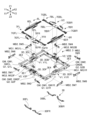
- FIG. 3 is an exploded perspective view of the optical device. It is an exploded perspective view of a module drive device.
- FIG. 3 is a perspective view of a module holder to which various members are attached. It is a figure which shows the top surface and bottom surface of a module holding body.
- FIG. 3 is a perspective view of a connecting member to which various members are attached. It is a figure which shows the top surface and bottom surface of a connection member.
- FIG. 3 is a right side view of a metal member to which a shape memory alloy wire is attached.
- FIG. 3 is a front view of a metal member to which a shape memory alloy wire is attached.
- FIG. 2 is a perspective view of a metal member, a conductive member, a current-carrying member, and a shape memory alloy wire.
- FIG. 3 is a diagram showing a path of current flowing through the first wire. It is a figure which shows the path of the electric current which flows through a 2nd wire.
- FIG. 1 It is a figure which shows the path of the electric current which flows through a 7th wire. It is a figure which shows the path of the electric current which flows through an 8th wire. It is a table showing the expansion and contraction state of the shape memory alloy wire when realizing the movement of the module holder. It is a front view of a module holding body, a connection member, and a base member. It is a right view of a module holding body, a connection member, and a base member. It is a top view of a module holding body, a connection member, and a base member. It is an exploded perspective view of a lens drive device. FIG.
- FIG. 2 is a perspective view of a module-side metal member, a leaf spring, a current-carrying member, and a module-side shape memory alloy wire. It is a top view of a module side movable metal member and a leaf spring. It is a figure which shows the path of the electric current which flows through the 7th wire which comprises a module side drive part. It is a figure which shows the path of the electric current which flows through the 8th wire which comprises a module side drive part. It is a table showing the expansion and contraction state of the module-side shape memory alloy wire when realizing the movement of the lens holder.
- FIG. 3 is a perspective view of a module-side buried current-carrying member, a third buried current-carrying member, and an intermediate current-carrying member.
- FIG. 1 is a perspective view of an optical device 150 with a camera module MD, which is an example of an optical module, attached thereto
- FIG. 2 is an exploded perspective view of the optical device 150 including a module drive device 100
- FIG. 2 is an exploded perspective view of the module drive device 100.
- module drive device 100 is a camera module drive device.
- X1 represents one direction of the X-axis that constitutes a three-dimensional orthogonal coordinate system
- X2 represents the other direction of the X-axis
- Y1 represents one direction of the Y-axis constituting the three-dimensional orthogonal coordinate system
- Y2 represents the other direction of the Y-axis
- Z1 represents one direction of the Z axis that constitutes the three-dimensional orthogonal coordinate system
- Z2 represents the other direction of the Z axis.
- the X1 side of the optical device 150 corresponds to the front side (front side) of the optical device 150
- the X2 side of the optical device 150 corresponds to the rear side (back side) of the optical device 150.
- the Y1 side of the optical device 150 corresponds to the left side of the optical device 150, and the Y2 side of the optical device 150 corresponds to the right side of the optical device 150.
- the Z1 side of the optical device 150 corresponds to the upper side (subject side) of the optical device 150, and the Z2 side of the optical device 150 corresponds to the lower side (imaging element side) of the optical device 150. The same applies to other members in other figures.
- the module drive device 100 that constitutes the optical device 150 includes a cover member 4 that is a part of the fixed side member FB.
- the cover member 4 is configured to function as a part of a housing HS that covers each member that constitutes the module drive device 100.
- the cover member 4 is made of non-magnetic metal.
- the cover member 4 may be made of magnetic metal.
- the cover member 4 has a box-like outer shape that defines a housing portion 4S.
- a camera module MD is housed in the housing section 4S.
- the cover member 4 includes a rectangular cylindrical outer peripheral wall 4A and a rectangular annular flat top plate that is provided so as to be continuous with the upper end (Z1 side end) of the outer peripheral wall 4A. It has a part 4B. A rectangular opening 4K is formed in the center of the top plate portion 4B.
- the outer peripheral wall portion 4A includes a first side plate portion 4A1 to a fourth side plate portion 4A4. The first side plate portion 4A1 and the third side plate portion 4A3 are opposed to each other, and the second side plate portion 4A2 and the fourth side plate portion 4A4 are opposed to each other.
- the first side plate portion 4A1 and the third side plate portion 4A3 extend perpendicularly to the second side plate portion 4A2 and the fourth side plate portion 4A4.
- the cover member 4 is bonded to the base member 8 with an adhesive.
- the adhesive is, for example, a photocurable adhesive.
- the photocurable adhesive is, for example, an ultraviolet curable adhesive or a visible light curable adhesive.
- the adhesive may be a thermosetting adhesive, a moisture curing adhesive, or the like. The same applies to the adhesive described below that joins one member to another member or adhesively fixes one member to another member.
- the base member 8 joined to the cover member 4 with an adhesive constitutes a housing HS together with the cover member 4.
- the camera module MD is an example of an optical module, and as shown in FIG. 2, includes a lens drive device LD, a lens body LS held by the lens drive device LD, and a substrate (flexible).
- the image sensor IS is fixed to a magnetic substrate FC).
- the spacer SP is fixed to the lens driving device LD, and the flexible substrate FC on which the image sensor IS is mounted is fixed to the spacer SP.
- a frame-shaped spacer SP is arranged between the lens drive device LD and the flexible substrate FC.
- the image sensor IS is housed in a space formed between the spacer SP and the flexible substrate FC, with its imaging surface exposed to the opening of the spacer SP.
- An IR cut filter may be arranged between the lens body LS and the image sensor IS. In this case, the IR cut filter may be attached to the upper surface of the frame of the spacer SP.
- the flexible substrate FC is a flexible substrate on which a wiring pattern for connecting the image sensor IS and a device outside the module drive device 100 is formed.
- the flexible substrate FC is a flexible printed circuit board configured to be repeatedly deformable.
- the image sensor IS may be mounted on a rigid substrate.
- the rigid board may be connected to the flexible board FC and connected to the outside via the flexible board FC. With this configuration, the flexible substrate FC can absorb the movement of the rigid substrate.
- the camera module MD is a camera module equipped with a shape memory alloy wire type module-side drive section DMx (see FIG. 24).
- the camera module MD may be a camera module including a drive unit of another type such as a voice coil motor type including a magnet and a coil or a piezoelectric type.
- the module-side drive unit DMx of the camera module MD is configured to move the lens body LS along the Z-axis direction, which is the optical axis direction of the lens body LS, on the Z1 side of the image sensor IS. It is configured. By moving the lens body LS in this manner, the camera module MD can realize an automatic focus adjustment function, which is one of the lens adjustment functions. Specifically, the camera module MD moves the lens body LS in a direction away from the image sensor IS to enable macro photography, and moves the lens body LS in a direction toward the image sensor IS to enable infinity photography. do.
- the camera module MD may be configured to be able to move the lens body LS in at least one of the X-axis direction and the Y-axis direction. By moving the lens body LS in this manner, the camera module MD may realize an image stabilization function, which is another one of the lens adjustment functions.
- FIG. 1 shows the states of the lens body LS and the lens driving device LD when the camera module MD is in a neutral state (neutral position).
- the neutral state of the camera module MD is when the lens body LS is located in the middle of the movable range in the Z-axis direction. means the state of being Typically, in the neutral state of the camera module MD, the lens body LS is located at the center of the movable range in the Z-axis direction.
- the initial state of the camera module MD when power is not supplied to the module-side drive unit DMx may be a neutral state.
- the camera module MD may be a fixed focus camera module. That is, the lens body LS may be arranged so as to be immovable relative to the image sensor IS.
- the housing HS of the module driving device 100 accommodates a driving part DM, a module holder 2, a connecting member 3, a metal member 5, an upper conductive member UC, a lower conductive member LC, etc. has been done.
- the drive unit DM includes a shape memory alloy wire SA that is an example of a shape memory actuator.
- the shape memory alloy wire SA includes first wire SA1 to eighth wire SA8 having approximately the same length and approximately the same diameter.
- the drive unit DM can move the module holder 2 using contraction of the shape memory alloy wire SA.
- the shape memory alloy wire SA when one or more of the first wire SA1 to the eighth wire SA8 contracts, the module holder 2 moves, and this movement causes another one or more to be stretched (stretched). It is configured so that In the illustrated example, the first wire SA1 to the fourth wire SA4 are also referred to as the first shape memory alloy wire SC1, and the fifth wire SA5 to the eighth wire SA8 are also referred to as the second shape memory alloy wire SC2.
- the drive unit DM is configured to realize movement of the movable member MB in three degrees of freedom. Movement with three degrees of freedom includes rotation (rotation) around the first direction (Z-axis direction), which is the optical axis direction, and rotation (oscillation) around the second direction (X-axis direction) perpendicular to the first direction. ), and rotation (oscillation) around a third direction (Y-axis direction) perpendicular to the first and second directions.
- the first direction is a direction parallel to the first rotation axis RX1 that coincides with the optical axis OA of the lens body LS
- the second direction is a direction parallel to the second rotation axis RX2.
- the third direction is a direction parallel to the third rotation axis RX3.
- the axis of the second rotating shaft RX2 is orthogonal to the axis of the first rotating shaft RX1
- the axis of the third rotating shaft RX3 is orthogonal to the axis of the first rotating shaft RX1.
- the axis of the second rotation axis RX2 and the axis of the third rotation axis RX3 are in a twisted positional relationship and are orthogonal to each other when viewed along the axial direction of the first rotation axis RX1.
- the axis of the second rotation axis RX2 and the axis of the third rotation axis RX3 may be orthogonal on the same plane. That is, the first rotation axis RX1, the second rotation axis RX2, and the third rotation axis RX3 may be rotation axes orthogonal to each other.
- the optical axis direction includes the direction of the optical axis OA with respect to the lens body LS and the direction parallel to the optical axis OA.
- the second rotation axis RX2 is also called a first swing axis
- the third rotation axis RX3 is also called a second swing axis.
- the neutral state of the module drive device 100 is within the rotatable range of the module holder 2. It means a state located in the middle. Typically, in the neutral state of the module drive device 100, the module holder 2 is located at the center of the rotatable range around the first rotation axis RX1. The same applies to the case where the module holder 2 is swingable around the second rotation axis RX2 and the case where the module holder 2 is swingable around the third rotation axis RX3.
- the initial state of the module drive device 100 when power is not supplied to the drive unit DM may be a neutral state.
- the imaging surface of the image sensor IS receives light from the lens body LS arranged opposite to the image sensor IS. It is perpendicular to the axis OA.
- the central axis of the image sensor IS (imaging surface) coincides with the optical axis OA of the lens body.
- the imaging surface of the image sensor IS is a surface parallel to the upper surface of the image sensor IS, which is the object-side surface.
- the movable member MB is a member driven by the drive unit DM.
- the movable member MB includes a module holder 2 that can hold the camera module MD, and a connecting member 3 that is connected to the module holder 2 so that the module holder 2 can swing.
- Camera module MD may be included in movable member MB.
- the module holder 2 is configured to be able to hold a camera module MD having a lens body LS and an image sensor IS.
- the module holder 2 is formed by injection molding a synthetic resin such as liquid crystal polymer (LCP).
- LCP liquid crystal polymer
- the module holder 2 includes a rectangular cylindrical outer peripheral wall 2A and a rectangular annular wall that is continuous with the upper end (Z1 side end) of the outer peripheral wall 2A.
- the flange portion 2G includes a left front flange portion 2GFL formed at the front left corner of the module holder 2, a right front flange portion 2GFR formed at the front right corner of the module holder 2, a module It includes a left rear flange portion 2GBL formed at the left rear corner of the holder 2 and a right rear flange portion 2GBR formed at the right rear corner of the module holder 2.
- the engaging portion 2T is a portion configured to engage with a portion of the connecting member 3.
- the engaging part 2T includes a left engaging part 2TL (see FIG. 5) formed to protrude outward from the left side of the outer peripheral wall 2A, and a left engaging part 2TL (see FIG. 5) that is formed to protrude outward from the right side of the outer peripheral wall 2A.
- the right engaging portion 2TR is formed to protrude.
- the module holder 2 is configured to function as a cover member for the camera module MD.
- the lens drive device LD is configured to be bonded to the lower end of the outer peripheral wall 2A with an adhesive.
- the connecting member 3 is configured so that the module holder 2 can swing around a third rotation axis RX3 that intersects with the optical axis direction.
- the connecting member 3 is formed by injection molding a synthetic resin such as liquid crystal polymer (LCP).
- LCP liquid crystal polymer
- the connecting member 3 has a rectangular annular frame portion arranged to surround the rectangular opening 3K.
- the frame has four sides 3E (first side 3E1 to fourth side 3E4).
- the connecting member 3 has an engaging portion V configured to engage with a corresponding portion of another member.
- the engaging portion V is configured to engage with a first engaging portion V1 configured to engage with a portion of the module holder 2 and with a portion of the base member 8. It includes a second engaging portion V2.
- the first engagement portion V1 includes a first left engagement portion V1L formed at the center of the second side 3E2 and a first right engagement portion V1L formed at the center of the fourth side 3E4. Contains the joint V1R.
- the second engaging portion V2 includes a second front engaging portion V2F formed at the center of the first side 3E1 and a second rear engaging portion V2B formed at the center of the third side 3E3. ,including.
- the upper conductive member UC is a flexible conductive member that connects two members that move relative to each other above the movable member MB.
- the upper conductive member UC is made of a metal plate whose main material is, for example, a copper alloy, a titanium-copper alloy (titanium-copper), or a copper-nickel alloy (nickel-tin-copper).
- the upper conductive member UC includes a first conductive member 6 that connects the module holder 2 and the connecting member 3, and a second conductive member 7 that connects the connecting member 3 and the base member 8.
- the first conductive member 6 includes a left conductive member 6L and a right conductive member 6R.
- the second conductive member 7 includes a front conductive member 7F and a rear conductive member 7B.
- the front conductive member 7F includes a left front conductive member 7FL and a right front conductive member 7FR
- the rear conductive member 7B includes a left rear conductive member 7BL and a right rear conductive member 7BR.
- the lower conductive member LC is a flexible conductive member that connects two members that move relative to each other below the movable member MB, and is also referred to as the third conductive member 9.
- the third conductive member 9 is made of a metal plate whose main material is, for example, a copper alloy, a titanium-copper alloy (titanium-copper), or a copper-nickel alloy (nickel-tin-copper).
- the third conductive member 9 includes four conductive members (left front conductive member 9FL, right front conductive member 9FR, left rear conductive member 9BL, and right rear conductive member 9BR).
- the base member 8 is formed by injection molding using a synthetic resin such as liquid crystal polymer (LCP).
- LCP liquid crystal polymer
- the base member 8 has a substantially rectangular outline when viewed from above, and has an opening 8K in the center, as shown in FIG. Specifically, the base member 8 has four sides 8E (first side 8E1 to fourth side 8E4) arranged to surround the opening 8K.
- the base member 8 has an engaging portion 8T configured to engage with a corresponding portion of another member.
- the engaging portion 8T is a portion configured to engage with a portion of the connecting member 3.
- the engaging portion 8T includes a front engaging portion 8TF formed at the center of the first side 8E1, a rear engaging portion 8TB formed at the center of the third side 8E3, including.
- the metal member 5 is configured so that the end of the shape memory alloy wire SA is fixed.
- the metal members 5 include eight lower metal members 5F (first lower terminal plate 5F1 to eighth lower terminal plate 5F8) and eight upper metal members 5M (first upper terminal plate 5M1 to eighth upper terminal plate 5M8).
- first lower metal members 5F first lower terminal plate 5F1 to fourth lower terminal plate 5F4
- the eight lower metal members 5F are configured to be fixed to the module holder 2.
- the remaining four of the 5F are configured to be fixed to the base member 8.
- the eight upper metal members 5M are configured to be fixed to the connecting member 3.
- the shape memory alloy wire SA is arranged along the inner surface of the outer peripheral wall portion 4A of the cover member 4, and is configured so that the movable member MB can be moved relative to the fixed member FB.
- the shape memory alloy wire SA includes a first wire SA1 to an eighth wire SA8, as shown in FIG.
- the holding body 2 is configured to be movable.
- each of the first wire SA1 to the eighth wire SA8 has one end fixed to the lower metal member 5F by crimping, welding, etc., and the other end being crimped, welding, etc. is fixed to the upper metal member 5M.
- the first rotating body Q1 is a rotating body disposed between the module holding body 2 and the connecting member 3
- the second rotating body Q2 is a rotating body disposed between the connecting member 3 and the base member 8. It is.
- the first rotating body Q1 and the second rotating body Q2 are balls (spheres) made of a magnetic material (magnetic metal).
- the first rotating body Q1 and the second rotating body Q2 may be made of a non-magnetic material such as plastic, non-magnetic metal, or ceramic.
- the first rotating body Q1 and the second rotating body Q2 may have a shape other than a sphere, such as a cylindrical body.
- the first rotating body Q1 includes a first left rotating body Q1L and a first right rotating body Q1R, which are arranged to face each other across the optical axis OA in the Y-axis direction.
- a line connecting the center of the first left rotating body Q1L and the center of the first right rotating body Q1R constitutes the axis of the third rotation axis RX3.
- the second rotating body Q2 includes a second front rotating body Q2F and a second rear rotating body Q2B, which are arranged to face each other across the optical axis OA in the X-axis direction.
- a line connecting the center of the second front rotating body Q2F and the center of the second rear rotating body Q2B constitutes the axis of the second rotating shaft RX2.
- the first magnet MG1 and the second magnet MG2 are arranged so that the module holder 2 and the connecting member 3 can be attracted to each other with the first rotating body Q1 in between.
- the first magnet MG1 is attached to the upper surface side of the connecting member 3, and the second magnet MG2 is attached to the lower surface side of the module holder 2.
- the first magnet MG1 and the second magnet MG2 are rectangular parallelepiped permanent magnets, and are bipolarly magnetized in the Z-axis direction.
- the first magnet MG1 and the second magnet MG2 are arranged so that the S pole of the first magnet MG1 and the N pole of the second magnet MG2 face each other with the first rotating body Q1 in between in the Z-axis direction.
- the side is magnetized to the north pole, and the bottom side is magnetized to the south pole.
- the first magnet MG1 includes a first left magnet MG1L that is adhesively fixed to the upper side of the first left engaging portion V1L located at the center of the second side portion 3E2 of the connecting member 3; a first right side magnet MG1R that is adhesively fixed to the upper side of the first right side engaging part V1R located at the center of the fourth side part 3E4 of the first right side magnet MG1R.
- the second magnet MG2 includes a second left magnet MG2L that is adhesively fixed to the lower side of the left side engaging part 2TL on the left side of the outer peripheral wall 2A of the module holder 2, and a second left magnet MG2L that is adhesively fixed to the lower side of the left engaging part 2TL on the left side of the outer peripheral wall 2A of the module holder 2. It includes a second right side magnet MG2R that is adhesively fixed to the lower side of the right side engaging portion 2TR on the right side surface.
- the third magnet MG3 and the fourth magnet MG4 are arranged so that the connecting member 3 and the base member 8 can be attracted to each other with the second rotating body Q2 in between.
- the third magnet MG3 is attached to the upper surface side of the connecting member 3, and the fourth magnet MG4 is attached to the lower surface side of the base member 8.
- the third magnet MG3 and the fourth magnet MG4 are rectangular parallelepiped permanent magnets, and are bipolarly magnetized in the Z-axis direction.
- the third magnet MG3 and the fourth magnet MG4 are arranged so that the S pole of the third magnet MG3 and the N pole of the fourth magnet MG4 face each other across the second rotating body Q2 in the Z-axis direction.
- the side is magnetized to the north pole, and the bottom side is magnetized to the south pole.
- the third magnet MG3 includes a third front magnet MG3F that is adhesively fixed to the upper side of the second front engaging portion V2F located at the center of the first side portion 3E1 of the connecting member 3;
- a third rear magnet MG3B is adhesively fixed to the upper side of the second rear engaging portion V2B located at the center of the third side portion 3E3.
- the fourth magnet MG4 includes a fourth front magnet MG4F that is adhesively fixed to the lower side of the front engaging portion 8TF located at the center of the first side 8E1 of the base member 8, and a fourth front magnet MG4F that is adhesively fixed to the lower side of the front engaging portion 8TF located at the center of the first side 8E1 of the base member 8; It includes a fourth rear magnet MG4B that is adhesively fixed to the lower side of the rear engaging portion 8TB located in the center.
- FIG. 4 is a perspective view of the module holder 2 to which various members are attached.
- FIG. 5 is a diagram showing the top and bottom surfaces of the module holder 2.
- FIG. 6 is a perspective view of the connecting member 3 to which various members are attached.
- FIG. 7 is a diagram showing the top and bottom surfaces of the connecting member 3.
- FIG. 8 is a perspective view of the base member 8 to which various members are attached.
- FIG. 9 is a diagram showing the top and bottom surfaces of the base member 8. As shown in FIG.
- the third lower terminal plate 5F3 is fixed to the front surface of the side flange portion 2GFL
- the third lower terminal plate 5F3 is fixed to the rear surface of the left rear flange portion 2GBL (see FIG. 5) of the module holder 2
- the fourth lower terminal plate 5F4 is fixed to the front surface of the side flange portion 2GFL. It is fixed to the rear surface of the right rear flange portion 2GBR of the module holder 2.
- the first lower terminal plate 5F1 to the fourth lower terminal plate 5F4 attached to the module holder 2 constitute the first movable part MB1 together with the module holder 2.
- the first lower terminal plate 5F1 to the fourth lower terminal plate 5F4 are fixed to the flange portion 2G with adhesive.
- the left conductive member 6L includes an inner fixed portion 6IL fixed to the module holder 2, an outer fixed portion 6EL fixed to the connecting member 3, an inner fixed portion 6IL and an outer fixed portion 6EL. It has an elastic portion 6GL that connects the.
- the right conductive member 6R includes an inner fixed part 6IR fixed to the module holder 2, an outer fixed part 6ER fixed to the connecting member 3, and an elastic part 6GR connecting the inner fixed part 6IR and the outer fixed part 6ER. has.
- the inner fixed portion 6IR is placed on the upper end surface of the right pedestal portion 2DR formed on the right side surface of the outer peripheral wall portion 2A of the module holder 2, and is fixed to the right pedestal portion 2DR with adhesive.
- the inner fixed portion 6IL is placed on the upper end surface of the left pedestal portion 2DL (see FIG. 5) formed on the left side surface of the outer peripheral wall portion 2A of the module holder 2, and is fixed to the left pedestal portion 2DL with adhesive. There is.
- the left front conductive member 9FL includes an inner fixed portion 9IFL fixed to the module holder 2, an outer fixed portion 9EFL fixed to the base member 8, an inner fixed portion 9IFL and an outer fixed portion 9EFL. It has an elastic portion 9GFL that connects the.
- the right front conductive member 9FR includes an inner fixed portion 9IFR fixed to the module holder 2, an outer fixed portion 9EFR fixed to the base member 8, and an elastic portion 9GFR connecting the inner fixed portion 9IFR and the outer fixed portion 9EFR. , has.
- the left rear conductive member 9BL includes an inner fixed part 9IBL fixed to the module holder 2, an outer fixed part 9EBL fixed to the base member 8, and an elastic part 9GBL connecting the inner fixed part 9IBL and the outer fixed part 9EBL. and has.
- the right rear conductive member 9BR includes an inner fixed portion 9IBR fixed to the module holder 2, an outer fixed portion 9EBR fixed to the base member 8, and an elastic portion 9GBR connecting the inner fixed portion 9IBR and the outer fixed portion 9EBR. and has.
- the inner fixed portion 9IFL is fixed to the lower surface of the left front flange portion 2GFL with an adhesive
- the inner fixed portion 9IFR is fixed to the lower surface of the right front flange portion 2GFR with an adhesive
- the inner fixed portion 9IBL is fixed to the lower surface of the right front flange portion 2GFR with an adhesive
- the inner fixed portion 9IBR is fixed to the lower surface of the right rear flange portion 2GBR with an adhesive.
- a first groove G1 for receiving the first rotating body Q1 is formed on the upper end surface of the engaging portion 2T of the module holder 2.
- the first groove G1 is an arcuate groove configured to extend along the circumference of a circle centered on the optical axis OA.
- the first groove portion G1 includes a first left groove portion G1L formed on the upper surface of the left side engaging portion 2TL, and a first groove portion G1L formed on the upper surface of the right side engaging portion 2TR. It includes the right groove portion G1R.
- the first left groove G1L is formed to receive the first left rotating body Q1L
- the first right groove G1R is formed to receive the first right rotating body Q1R.
- a broken line indicates an annular region sandwiched between two concentric circles centered on the optical axis OA, and each of the first left groove portion G1L and the first right groove portion G1R is a part of the annular region. represents.
- the first groove G1 is configured such that the module holder 2 and the connecting member 3, which are connected via the first rotating body Q1, can rotate relative to each other around the optical axis OA. ing.
- a second accommodating portion N2 for receiving the second magnet MG2 is formed on the lower end surface of the engaging portion 2T of the module holder 2.
- the second accommodating portion N2 is a rectangular parallelepiped-shaped recess configured to extend along the side surface of the outer peripheral wall portion 2A.
- the second accommodating part N2 includes a second left accommodating part N2L formed on the lower surface of the left engaging part 2TL, and a second accommodating part N2L formed on the lower surface of the right engaging part 2TR. It includes a second right housing part N2R.
- the second left housing part N2L is formed to receive the second left magnet MG2L
- the second right housing part N2R is formed to receive the second right magnet MG2R.
- the module holder 2 is configured such that the first buried current-carrying member 20 is embedded therein.
- the first embedded energizing member 20 is a member used for energizing the first shape memory alloy wire SC1 and the second shape memory alloy wire SC2, and is embedded in the module holder 2 by insert molding. More specifically, the first buried current-carrying member 20 includes four mutually independent members (back-side current-carrying member 20B, front-side current-carrying member 20F, left-side current-carrying member 20L, and right-side current-carrying member 20R).
- the third upper terminal plate 5M3 is fixed to the right side of the rear surface of the third side 3E3 of the connecting member 3
- the fourth upper terminal plate 5M4 is fixed to the right side of the rear side of the third side 3E3 of the connecting member 3. It is fixed on the left side of the rear of 3E3.
- the fifth upper terminal plate 5M5 is fixed to the rear side of the left side of the second side 3E2 of the connecting member 3
- the sixth upper terminal plate 5M6 is fixed to the front side of the left side of the second side 3E2 of the connecting member 3.
- the seventh upper terminal plate 5M7 is fixed to the front side of the right side of the fourth side 3E4 of the connecting member 3
- the eighth upper terminal plate 5M8 is fixed to the front side of the right side of the fourth side 3E4 of the connecting member 3.
- the first upper terminal plate 5M1 to the eighth upper terminal plate 5M8 attached to the connecting member 3 constitute the second movable part MB2 together with the connecting member 3.
- the first upper terminal plate 5M1 to the eighth upper terminal plate 5M8 are fixed to the connecting member 3 with adhesive.
- the outer fixed portion 6ER of the right conductive member 6R is placed on the upper end surface of the right pedestal portion 3DR formed at the center of the fourth side portion 3E4 of the connecting member 3, and is placed on the right side with adhesive. It is fixed to the pedestal part 3DR.
- the outer fixed portion 6EL of the left conductive member 6L is placed on the upper end surface of the left pedestal portion 3DL formed at the center of the second side portion 3E2 of the connecting member 3, and is fixed to the left pedestal portion 3DL with adhesive. There is.
- the left front conductive member 7FL includes an inner fixed portion 7IFL fixed to the connecting member 3, an outer fixed portion 7EFL fixed to the base member 8, an inner fixed portion 7IFL, and an outer fixed portion 7EFL. It has an elastic portion 7GFL that connects the.
- the right front conductive member 7FR includes an inner fixed portion 7IFR fixed to the connecting member 3, an outer fixed portion 7EFR fixed to the base member 8, and an elastic portion 7GFR connecting the inner fixed portion 7IFR and the outer fixed portion 7EFR. has.
- the left rear conductive member 7BL includes an inner fixed part 7IBL fixed to the connecting member 3, an outer fixed part 7EBL fixed to the base member 8, and an elastic part 7GBL connecting the inner fixed part 7IBL and the outer fixed part 7EBL.
- the right rear conductive member 7BR includes an inner fixed portion 7IBR fixed to the connecting member 3, an outer fixed portion 7EBR fixed to the base member 8, and an elastic portion 7GBR connecting the inner fixed portion 7IBR and the outer fixed portion 7EBR. , has.
- the inner fixed portion 7IFL and the inner fixed portion 7IFR are placed on the upper end surface of the front pedestal portion 3DF formed at the center of the first side portion 3E1 of the connecting member 3, and are attached to the front pedestal portion with adhesive. Fixed to 3DF.
- the inner fixed portion 7IBL and the inner fixed portion 7IBR are placed on the upper end surface of the rear pedestal portion 3DB formed at the center of the third side portion 3E3 of the connecting member 3, and fixed to the rear pedestal portion 3DB with adhesive. has been done.
- a first recess H1 for holding the first rotating body Q1 is formed in the lower end surface of the first engaging portion V1 of the connecting member 3.
- the first recess H1 is a recess configured to regulate (maintain) the position of the first rotating body Q1, that is, so that the first rotating body Q1 slides and rotates at that position without rolling.
- the first recess H1 is formed in the first left recess H1L formed in the lower surface of the first left engaging part V1L and in the lower surface of the first right engaging part V1R. It includes a first right side recess H1R.
- the first left recess H1L is formed to receive the first left rotating body Q1L
- the first right recess H1R is formed to receive the first right rotating body Q1R.
- the first recess H1 has an optical axis OA on a straight line connecting the center of the first left rotor Q1L held in the first left recess H1L and the center of the first right rotor Q1R held in the first right recess H1R. is configured so that it is located.
- the circumferential length of the first recess H1 is configured to be shorter than the circumferential length of the first groove G1.
- the first recess H1 does not need to have an arcuate shape centered on the optical axis OA in a plan view (bottom view), but a straight line in the tangential direction of a circle centered on the optical axis OA as shown in FIG. It may have any shape, such as a shape extending to .
- a second recess H2 for holding the second rotating body Q2 is formed on the lower end surface of the second engaging portion V2 of the connecting member 3.
- the second recess H2 is a recess configured to regulate (maintain) the position of the second rotating body Q2, that is, so that the second rotating body Q2 slides and rotates at that position without rolling.
- the second recess H2 is formed in the second front recess H2F formed in the lower surface of the second front engaging part V2F and in the lower surface of the second rear engaging part V2B. It includes a second rear recess H2B formed therein.
- the second front recess H2F is formed to receive the second front rotating body Q2F
- the second rear recess H2B is formed to receive the second rear rotating body Q2B.
- the second recess H2 allows light to be projected onto a straight line connecting the center of the second rear rotating body Q2B held in the second rear recess H2B and the center of the second front rotating body Q2F held in the second front recess H2F. It is configured such that the axis OA is located therein.
- the circumferential length of the second recess H2 is configured to be shorter than the circumferential length of the second groove G2.
- the second recess H2 does not need to have an arc shape centered on the optical axis OA in a plan view (bottom view), but a straight line in the tangential direction of a circle centered on the optical axis OA as shown in FIG. It may have any shape, such as a shape extending to .
- a first accommodating portion N1 for receiving the first magnet MG1 is formed on the upper end surface of the first engaging portion V1 of the connecting member 3.
- the first accommodating portion N1 is a rectangular parallelepiped-shaped recess configured to extend along the side portion 3E.
- the first accommodating part N1 includes a first left accommodating part N1L formed on the upper surface of the first left engaging part V1L, and an upper surface of the first right engaging part V1R.
- the first right housing portion N1R is formed in the first right housing portion N1R.
- the first left accommodating portion N1L is formed to receive the first left magnet MG1L
- the first right accommodating portion N1R is formed to receive the first right magnet MG1R.
- a third accommodating portion N3 for receiving a third magnet MG3 is formed on the upper end surface of the second engaging portion V2 of the connecting member 3.
- the third accommodating portion N3 is a rectangular parallelepiped-shaped recess configured to extend along the side portion 3E.
- the third accommodating part N3 includes a third front accommodating part N3F formed on the upper surface of the second front engaging part V2F and a second rear engaging part V2B. It includes a third rear housing part N3B formed on the top surface.
- the third front housing part N3F is formed to receive the third front magnet MG3F
- the third rear housing part N3B is formed to receive the third rear magnet MG3B.
- the connecting member 3 is configured such that the second buried current-carrying member 30 is embedded therein.
- the second embedded energizing member 30 is a member used for energizing the first shape memory alloy wire SC1, and is embedded in the connecting member 3 by insert molding. More specifically, the second buried energizing member 30 includes four mutually independent members (a left rear energizing member 30BL, a right rear energizing member 30BR, a left front energizing member 30FL, and a right front energizing member 30FR). .
- the seventh lower terminal plate 5F7 is fixed to the rear side of the left side of the second side 8E2, and the seventh lower terminal plate 5F7 is fixed to the rear side of the right side of the fourth side 8E4 of the base member 8. , is fixed to the front side of the right side of the fourth side portion 8E4 of the base member 8.
- the fifth lower terminal plate 5F5 to the eighth lower terminal plate 5F8 are fixed to the base member 8 with an adhesive.
- the outer fixed portion 7EFL of the left front conductive member 7FL and the outer fixed portion 7EFR of the right front conductive member 7FR are connected to the front pedestal portion 8DF formed at the center of the first side portion 8E1 of the base member 8. It is placed on the upper end surface of and fixed to the front pedestal part 8DF with adhesive.
- the outer fixed portion 7EBL of the left rear conductive member 7BL and the outer fixed portion 7EBR of the right rear conductive member 7BR are attached to the upper end surface of the rear pedestal portion 8DB formed at the center of the third side portion 8E3 of the base member 8. It is placed and fixed to the rear pedestal part 8DB with adhesive.
- the outer fixed portion 9EFL of the left front conductive member 9FL is placed on the upper end surface of the left front pedestal portion 8DFL formed at the center of the second side portion 8E2 of the base member 8. , is fixed to the left front pedestal part 8DFL with adhesive.
- the outer fixed portion 9EBL of the left rear conductive member 9BL is placed on the upper end surface of the left rear pedestal 8DBL formed at the center of the second side 8E2 of the base member 8, and is attached to the left rear pedestal with adhesive. It is fixed to section 8DBL.
- the outer fixed portion 9EFR of the right front conductive member 9FR is placed on the upper end surface of the right front pedestal portion 8DFR formed at the center of the fourth side portion 8E4 of the base member 8, and is attached to the right front pedestal portion 8DFR with adhesive. Fixed.
- the outer fixed portion 9EBR of the right rear conductive member 9BR is placed on the upper end surface of the right rear pedestal portion 8DBR formed at the center of the fourth side portion 8E4 of the base member 8, and is attached to the right rear pedestal with adhesive. It is fixed to part 8DBR.
- a second groove G2 for receiving the second rotating body Q2 is formed in the upper end surface of the engaging portion 8T of the base member 8.
- the second groove G2 is an arcuate groove configured to extend along the circumference of a circle centered on the optical axis OA.
- the second groove portion G2 is a second front groove portion G2F formed on the upper surface of the front side engaging portion 8TF, and a second groove portion G2F formed on the upper surface of the rear side engaging portion 8TB. It includes a second rear groove portion G2B.
- the second front groove G2F is formed to receive the second front rotating body Q2F
- the second rear groove G2B is formed to receive the second rear rotating body Q2B.
- a broken line indicates an annular region sandwiched between two concentric circles centered on the optical axis OA, and each of the second front groove portion G2F and the second rear groove portion G2B is a part of the annular region. represents something.
- the second groove G2 is configured such that the connecting member 3 and the base member 8, which are connected via the second rotating body Q2, can rotate relative to each other around the optical axis OA. There is.
- a fourth accommodating portion N4 for receiving the fourth magnet MG4 is formed on the lower end surface of the engaging portion 8T of the base member 8.
- the fourth accommodating portion N4 is a rectangular parallelepiped-shaped recess configured to extend along the side portion 8E.
- the fourth accommodating portion N4 includes a fourth front accommodating portion N4F formed on the lower surface of the front engaging portion 8TF and a lower surface of the rear engaging portion 8TB. It includes a fourth rear housing part N4B.
- the fourth front housing part N4F is formed to receive the fourth front magnet MG4F
- the fourth rear housing part N4B is formed to receive the fourth rear magnet MG4B.
- the base member 8 is configured such that a third buried current-carrying member 80 is embedded therein.
- the third embedded energizing member 80 is a member used for energizing the first shape memory alloy wire SC1 and the second shape memory alloy wire SC2, and is embedded in the base member 8 by insert molding. More specifically, the third buried current-carrying member 80 includes 22 mutually independent members (first current-carrying member CB1 to twenty-second current-carrying member CB22).
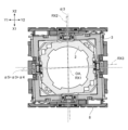
- FIG. 10 is a top view of the module holder 2, the connecting member 3, and the base member 8 combined with each other
- FIGS. 11 and 12 are a top view of the module holder 2, the connecting member 3, and the base member 8 combined with each other.
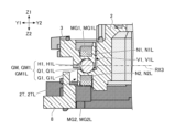
- 8 is a sectional view of FIG.
- FIG. 11 shows a cross section of the module holder 2, the connecting member 3, and the base member 8 in a plane parallel to the YZ plane including the cutting line CTL1 shown in FIG.
- a coarse dot pattern is applied to the module holder 2
- a fine dot pattern is applied to the connecting member 3
- an even finer dot pattern is applied to the base member 8.
- a fine cross pattern is attached to the north pole portion of the magnet
- a coarse cross pattern is attached to the south pole portion of the magnet.
- the guide mechanism GM is a mechanism that guides the rotation of the module holder 2 around the optical axis OA.
- the guide mechanism GM includes a first guide mechanism GM1 that guides the rotation of the module holder 2 around the optical axis OA with respect to the connecting member 3, and a connecting member 3 with respect to the base member 8 (which is connected to the connecting member 3). and a second guide mechanism GM2 that guides the rotation of the module holder 2 (including the module holder 2) around the optical axis OA.
- the first guide mechanism GM1 is, as shown in FIG. It is configured to include a first recessed portion H1 and a first rotating body Q1.
- the first guide mechanism GM1 includes a first left guide mechanism GM1L and a first right guide mechanism GM1R.
- the first left guide mechanism GM1L includes a first left groove G1L formed on the upper end surface of the left engaging portion 2TL, a first left recess H1L formed on the lower end surface of the first left engaging portion V1L, and It is configured to include a first left rotating body Q1L.
- the first right guide mechanism GM1R includes a first right groove portion G1R formed on the upper end surface of the right side engaging portion 2TR, a first right recessed portion H1R formed on the lower end surface of the first right side engaging portion V1R, and a first right side groove portion G1R formed on the upper end surface of the right side engaging portion 2TR. It is configured to include a right rotating body Q1R.
- the first left rotating body Q1L has an upper portion received in the first left recess H1L and a lower portion received in the first left groove G1L.
- the first left rotating body Q1L is arranged in the first left groove G1L so as to be able to roll within the first left groove G1L along the circumference of a circle centered on the optical axis OA, and It is arranged in the first left recess H1L so as to slide and rotate (not roll) within the first left recess H1L. Therefore, the first left guide mechanism GM1L can guide the rotation of the module holder 2 about the first rotation axis RX1 (optical axis OA) with respect to the connecting member 3. The same applies to the first right guide mechanism GM1R.
- the S pole part of the first left magnet MG1L is housed in the first left housing part N1L formed on the upper surface of the first left engaging part V1L, and the second left housing is formed on the lower surface of the left engaging part 2TL.
- the N-pole portion of the second left side magnet MG2L housed in the portion N2L is arranged to face the first left side rotating body Q1L.
- the first guide mechanism GM1 can maintain the state in which the module holder 2 and the connecting member 3 are attracted to each other even while the module holder 2 is rotating with respect to the connecting member 3, and the module holder 2 and the connecting member 3 can maintain a state in which they are attracted to each other. It is possible to suppress or prevent the connecting members 3 from separating from each other. Therefore, the first guide mechanism GM1 can suppress or prevent the module holder 2 from being erroneously tilted with respect to the connecting member 3.
- the second guide mechanism GM2 includes a second groove G2 formed on the upper end surface of the engaging portion 8T of the base member 8 and a lower end surface of the second engaging portion V2 of the connecting member 3. It is configured to include a second recess H2 and a second rotating body Q2. Specifically, the second guide mechanism GM2 includes a second front guide mechanism GM2F and a second rear guide mechanism GM2B.
- the second front guide mechanism GM2F includes a second front groove portion G2F formed on the upper end surface of the front engaging portion 8TF, a second front recess H2F formed on the lower end surface of the second front engaging portion V2F, and
- the second rear guide mechanism GM2B includes a second front rotary body Q2F, a second rear groove part G2B formed on the upper end surface of the rear engaging part 8TB, and a second rear engaging part V2B. It is configured to include a second rear side recess H2B formed in the lower end surface of and a second rear rotating body Q2B.
- the second rear rotating body Q2B has an upper portion received in the second rear recess H2B and a lower portion received in the second rear groove G2B. It is being In the illustrated example, the second rear rotating body Q2B is arranged in the second rear groove G2B so that it can roll within the second rear groove G2B along the circumference of a circle centered on the optical axis OA. , and is arranged in the second rear recess H2B so as to slide and rotate (not roll) within the second rear recess H2B.
- the second rear guide mechanism GM2B can guide the rotation of the connecting member 3 (including the module holder 2) with respect to the base member 8 around the first rotation axis RX1 (optical axis OA).
- the N-pole portion of the fourth rear magnet MG4B housed in the fourth rear housing portion N4B is arranged to face the second rear rotating body Q2B.
- the second guide mechanism GM2 maintains the state in which the base member 8 and the connecting member 3 are attracted to each other even while the connecting member 3 (including the module holder 2) is rotating with respect to the base member 8. Therefore, it is possible to suppress or prevent the base member 8 and the connecting member 3 from separating from each other. Therefore, the second guide mechanism GM2 can suppress or prevent the connection member 3 (including the module holder 2) from being erroneously tilted with respect to the base member 8.
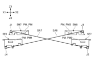
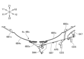
- FIG. 13 shows the seventh wire SA7 attached to each of the seventh upper terminal plate 5M7 and the seventh lower terminal plate 5F7, and the seventh wire SA7 attached to each of the eighth upper terminal plate 5M8 and the eighth lower terminal plate 5F8.
- 8 is a diagram when the eighth wire SA8 is viewed from the Y2 side (right side).
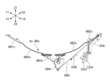
- FIG. 14 shows the seventh wire SA7 attached to each of the seventh upper terminal plate 5M7 and the seventh lower terminal plate 5F7, and the seventh wire SA7 attached to each of the eighth upper terminal plate 5M8 and the eighth lower terminal plate 5F8.
- FIG. 3 is a diagram of the eighth wire SA8 viewed from the X1 side (front side).
- the positional relationship of each member shown in FIGS. 13 and 14 corresponds to the positional relationship when the module drive device 100 is assembled. In FIGS. 13 and 14, illustration of other members is omitted for clarity.
- the following description with reference to FIGS. 13 and 14 relates to the combination of the seventh wire SA7 and the eighth wire SA8, but the combination of the first wire SA1 and the second wire SA2, the combination of the third wire SA3 and the fourth wire SA4 , and the combination of the fifth wire SA5 and the sixth wire SA6.
- one end of the seventh wire SA7 is fixed to the seventh upper terminal plate 5M7 at the holding portion J1 of the seventh upper terminal plate 5M7, and the other end of the seventh wire SA7 is fixed to the seventh lower terminal plate 5M7. It is fixed to the seventh lower terminal plate 5F7 at the holding portion J2 of 5F7.
- One end of the eighth wire SA8 is fixed to the eighth upper terminal plate 5M8 at the holding part J3 of the eighth upper terminal plate 5M8, and the other end of the eighth wire SA8 is fixed to the holding part J4 of the eighth lower terminal plate 5F8. It is fixed to the eighth lower terminal plate 5F8 at .
- the holding portion J1 is formed by bending a part of the seventh upper terminal plate 5M7. Specifically, a portion of the seventh upper terminal plate 5M7 forms the holding portion J1 by being bent while sandwiching the end (one end) of the seventh wire SA7. The end (one end) of the seventh wire SA7 is fixed to the holding part J1 by welding. The same applies to holding portions J2 to J4.
- the plate-like parts PM of the plurality of metal members 5 are arranged parallel to each other.
- the plate portion PM1 of the seventh upper terminal plate 5M7, the plate portion PM2 of the seventh lower terminal plate 5F7, the plate portion PM3 of the eighth upper terminal plate 5M8, and the eighth lower terminal plate are arranged parallel to each other along the XZ plane.
- the seventh wire SA7 and the eighth wire SA8 are arranged in a twisted positional relationship (so that they intersect three-dimensionally when viewed from the Y2 side). That is, the seventh wire SA7 and the eighth wire SA8 are arranged so as not to contact each other (become non-contact).
- one end of the seventh wire SA7 is at a higher position than the other end, as shown in FIG. 13, in a right side view from the Y2 side.
- the eighth wire SA8 is arranged so that one end thereof is higher than the other end, and the seventh wire SA7 and the eighth wire SA8 are arranged so as to intersect with each other.
- the first wire SA1 is arranged so that its one end is higher than the other end, and the second wire SA2 is arranged so that its one end is higher than the other end. Further, the first wire SA1 and the second wire SA2 are arranged to intersect with each other.
- the third wire SA3 is arranged so that its one end is higher than the other end
- the fourth wire SA4 is arranged so that its one end is higher than the other end. Further, the third wire SA3 and the fourth wire SA4 are arranged to intersect with each other.
- the fifth wire SA5 is arranged such that one end thereof is higher than the other end
- the sixth wire SA6 is arranged such that one end thereof is higher than the other end. Further, the fifth wire SA5 and the sixth wire SA6 are arranged to intersect with each other.
- the first wire SA1 to the eighth wire SA8 are all arranged so as to extend obliquely (non-parallel) to the X-axis and the Y-axis.
- the first wire SA1 and the second wire SA2 only need to be arranged so as to extend obliquely when viewed from the front, and do not need to intersect with each other when viewed from the front.
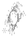
- FIG. 15 shows a metal member 5, a first electrically conductive member 6, a second electrically conductive member 7, a third electrically conductive member 9, a first buried electrically conductive member 20, a second embedded electrically conductive member 30, a third embedded electrically conductive member 80, and a shape memory It is a figure showing the positional relationship of alloy wire SA.
- FIG. 15 shows a metal member 5, a first conductive member 6, a second conductive member 7, a third conductive member 9, a first buried current carrying member 20, a second buried current carrying member 30, and a third buried current carrying member. 80 and a perspective view of the shape memory alloy wire SA.
- 16 to 19 are perspective views of a portion of the configuration shown in FIG. 15.
- FIG. 16 shows a state when the first current-carrying member CB1 of the third buried current-carrying member 80 is connected to a high potential, and the eighteenth current-carrying member CB18 of the third buried current-carrying member 80 is connected to a low potential.
- 17 shows the path of the current flowing through the first wire SA1
- FIG. 17 shows a state in which the second current-carrying member CB2 of the third buried current-carrying member 80 is connected to a high potential, and the eighteenth current-carrying member CB18 of the third buried current-carrying member 80 is connected to a high potential. shows the path of the current flowing through the second wire SA2 when it is connected to a low potential.
- FIG. 16 shows a state when the first current-carrying member CB1 of the third buried current-carrying member 80 is connected to a high potential, and the eighteenth current-carrying member CB18 of the third buried current-car
- FIG. 18 shows that when the eleventh current-carrying member CB11 of the third buried current-carrying member 80 is connected to a high potential and the sixth current-carrying member CB6 of the third buried current-carrying member 80 is connected to a low potential, the seventh wire SA7
- FIG. 19 shows the path of the current flowing through
- FIG. 19 shows that the third current-carrying member CB3 of the third buried current-carrying member 80 is connected to a high potential
- the sixth current-carrying member CB6 of the third buried current-carrying member 80 is connected to a low potential.
- 8 shows the path of the current flowing through the eighth wire SA8 when the current is applied.
- the current flows as indicated by the arrow AR1 in FIG.
- the current flows through the first wire SA1 as shown in FIG. Specifically, the current flows through the first energizing member CB1, the left front conductive member 7FL, the left front energizing member 30FL, the first upper terminal plate 5M1, the first wire SA1, the first lower terminal plate 5F1, and the front energizing member 20F. , and flows through the left front conductive member 9FL to the eighteenth current conducting member CB18.
- the current flows as indicated by the arrow AR2 in FIG.
- the current flows through the second wire SA2 as shown in FIG. Specifically, the current flows through the second energizing member CB2, the front right conductive member 7FR, the front right energizing member 30FR, the second upper terminal plate 5M2, the second wire SA2, the second lower terminal plate 5F2, and the front energizing member 20F. , and flows through the left front conductive member 9FL to the eighteenth current conducting member CB18.
- the path of the current flowing through the first wire SA1 and the path of the current flowing through the second wire SA2 partially overlap. Specifically, the two current paths overlap at the portions passing through the front current conducting member 20F, the left front conducting member 9FL, and the eighteenth current conducting member CB18. This configuration has the effect of reducing the number of parts.
- the current flows as indicated by the arrow AR3 in FIG.
- the current flows through the seventh wire SA7 as shown in FIG. Specifically, the current flows through the eleventh conductive member CB11, the seventh lower terminal plate 5F7, the seventh wire SA7, the seventh upper terminal plate 5M7, the right conductive member 6R, the right conductive member 20R, and the front right conductive member 9FR. and flows to the sixth current-carrying member CB6.
- the current flows as indicated by the arrow AR4 in FIG.
- the current flows through the eighth wire SA8 as shown in FIG. Specifically, the current flows through the third conductive member CB3, the eighth lower terminal plate 5F8, the eighth wire SA8, the eighth upper terminal plate 5M8, the right conductive member 6R, the right conductive member 20R, and the front right conductive member 9FR. and flows to the sixth current-carrying member CB6.
- the path of the current flowing through the seventh wire SA7 and the path of the current flowing through the eighth wire SA8 partially overlap. Specifically, the two current paths overlap at the portions passing through the right conductive member 6R, the right conductive member 20R, the front right conductive member 9FR, and the sixth conductive member CB6. This configuration has the effect of reducing the number of parts.
- FIGS. 15 to 19 members (metal member 5, first conductive member 6, second conductive member 7, third conductive member 9, first buried current conductive member 20) constituting the current conduction path of the shape memory alloy wire SA are shown.
- the second buried current-carrying member 30, and the third buried current-carrying member 80) two adjacent members are connected to each other. This connection is realized by welding or by conductive bonding material (conductive adhesive or solder).
- conductive bonding material conductive adhesive or solder
- the control device located outside the module drive device 100 controls the voltage applied to the third buried current-carrying member 80 connected to the first lower terminal plate 5F1 to the eighth lower terminal plate 5F8.
- the expansion and contraction of each of the wires SA1 to SA8 can be controlled.
- the control device controls the current supplied to each of the first wire SA1 to eighth wire SA8 via the third buried current-carrying member 80 connected to the first lower terminal plate 5F1 to the eighth lower terminal plate 5F8.
- the control device may be arranged within the module drive device 100.
- the control device may be a component of the module drive device 100.
- the control device rotates (rotates or rotates) the module holder 2 around at least one of the first rotation axis RX1, the second rotation axis RX2, and the third rotation axis RX3. (oscillation).
- the control device may realize an image stabilization function.
- FIG. 20 is a table showing the expansion and contraction states of the shape memory alloy wire SA when each of the three degrees of freedom of movement of the module holder 2 is realized. Specifically, “shrinkage” in FIG. 20 represents shrinking the shape memory alloy wire SA in the standard state, and “stretching” in FIG. 20 represents stretching the shape memory alloy wire SA in the standard state. .
- the reference state means the state of the shape memory alloy wire SA when the module drive device 100 is in a neutral state.
- FIG. 21 shows the three members (module holder 2, connecting member 3) when the module holder 2 and connecting member 3 rotate (swing) around the X axis (second rotation axis RX2) with respect to the base member 8. , and a front view of the base member 8).
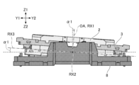
- FIG. 22 is a right side view of the three members when the module holder 2 rotates (swings) around the Y-axis (third rotation axis RX3) with respect to the connecting member 3.
- FIGS. 21 to 23 is a top view of the three members when the module holder 2 and the connecting member 3 are rotated (rotated) around the Z axis (first rotation axis RX1) with respect to the base member 8.
- a coarse dot pattern is applied to the module holder 2
- a fine dot pattern is applied to the connecting member 3
- an even finer dot pattern is applied to the base member 8.
- FIG. 21 is a front view of the three members when the module holder 2 and the connecting member 3 swing clockwise by an angle ⁇ 1 around the X axis (second rotation axis RX2) with respect to the base member 8.
- the control device swings the module holder 2 and the connecting member 3 clockwise around the X axis (second rotation axis RX2) with respect to the base member 8 when viewed from the front, the control device operates as shown in the table of FIG. , the fifth wire SA5 and the sixth wire SA6 are expanded by approximately the same amount of expansion, and the seventh wire SA7 and the eighth wire SA8 are contracted by approximately the same amount of contraction.
- stretching the two shape memory alloy wires SA by approximately the same amount of stretching means stretching the two shape memory alloy wires SA until the lengths of the two shape memory alloy wires SA become approximately the same predetermined length. It means to cause.
- shrinking the two shape memory alloy wires SA by approximately the same amount of contraction means contracting the two shape memory alloy wires SA until the lengths of the two shape memory alloy wires SA become approximately the same predetermined length. do. The same applies to the following description.
- the control device maintains the amount of expansion and contraction of the first shape memory alloy wire SC1 (first wire SA1 to fourth wire SA4).
- control device adjusts the amount of expansion and contraction of each of the first wire SA1 to eighth wire SA8 by individually adjusting the magnitude of the current supplied to each of the first wire SA1 to eighth wire SA8. Control as described above. Under the control of this control device, the drive unit DM swings the module holder 2 and the connecting member 3 clockwise around the X axis (second rotation axis RX2) with respect to the base member 8, as shown in FIG. can be moved.
- the control device rotates the module holder 2 and the connecting member 3 counterclockwise around the X axis (second rotation axis RX2) with respect to the base member 8 when viewed from the front, the control device rotates the module holder 2 and the connecting member 3 as shown in the table of FIG. , the fifth wire SA5 and the sixth wire SA6 are contracted by approximately the same amount of contraction, and the seventh wire SA7 and the eighth wire SA8 are expanded by approximately the same amount of expansion.
- the control device maintains the amount of expansion and contraction of the first shape memory alloy wire SC1 (first wire SA1 to fourth wire SA4).
- the control device controls the amount of expansion and contraction of each of the first wire SA1 to eighth wire SA8 as described above by individually adjusting the magnitude of the current supplied to each of the first wire SA1 to eighth wire SA8. do.
- the drive unit DM can swing the module holder 2 and the connecting member 3 counterclockwise around the X axis (second rotation axis RX2) with respect to the base member 8.
- FIG. 22 is a right side view of the three members when the module holder 2 is swung by an angle ⁇ 2 counterclockwise around the Y-axis (third rotation axis RX3) with respect to the connecting member 3 and the base member 8. be.
- the control device swings the module holder 2 counterclockwise around the Y-axis (third rotation axis RX3) with respect to the connecting member 3 in a right side view, the control device
- the first wire SA1 and the second wire SA2 are expanded by approximately the same amount of expansion, and the third wire SA3 and the fourth wire SA4 are contracted by approximately the same amount of contraction.
- the control device maintains the amount of expansion and contraction of the second shape memory alloy wire SC2 (fifth wire SA5 to eighth wire SA8).
- control device adjusts the amount of expansion and contraction of each of the first wire SA1 to eighth wire SA8 by individually adjusting the magnitude of the current supplied to each of the first wire SA1 to eighth wire SA8. Control as described above. Under the control of this control device, the drive unit DM swings the module holder 2 counterclockwise around the Y axis (third rotation axis RX3) with respect to the connecting member 3, as shown in FIG. Can be done.
- the control device controls the first The wire SA1 and the second wire SA2 are contracted by approximately the same amount of contraction, and the third wire SA3 and the fourth wire SA4 are expanded by approximately the same amount of expansion.
- the control device maintains the amount of expansion and contraction of the second shape memory alloy wire SC2 (fifth wire SA5 to eighth wire SA8).
- the control device adjusts the amount of expansion and contraction of each of the first wire SA1 to eighth wire SA8 by individually adjusting the magnitude of the current supplied to each of the first wire SA1 to eighth wire SA8. Control as described above. Under the control of this control device, the drive unit DM can swing the module holder 2 clockwise around the Y-axis (third rotation axis RX3) with respect to the connecting member 3.
- FIG. 23 shows that the connecting member 3 rotates counterclockwise around the Z-axis (first rotation axis RX1) with respect to the base member 8 by an angle ⁇ 3, and that the connecting member 3 rotates with respect to the base member 8 around the Z-axis (first FIG. 7 is a top view of the three members when the module holder 2 is rotated by an angle ⁇ 4 around the rotation axis RX1). That is, FIG. 23 is a top view of the three members when the module holder 2 is rotated by an angle ⁇ 5 counterclockwise around the Z axis (first rotation axis RX1) with respect to the base member 8. Angle ⁇ 5 is the sum of angle ⁇ 3 and angle ⁇ 4.
- control device adjusts the amount of expansion and contraction of each of the first wire SA1 to eighth wire SA8 by individually adjusting the magnitude of the current supplied to each of the first wire SA1 to eighth wire SA8. Control as described above. Under the control of this control device, the drive unit DM rotates the connecting member 3 counterclockwise around the Z-axis (first rotation axis RX1) with respect to the base member 8, as shown in FIG. 23, and , the module holder 2 can be rotated counterclockwise around the Z axis (first rotation axis RX1) with respect to the connecting member 3.
- control device When the control device rotates the connecting member 3 clockwise around the Z-axis (first rotation axis RX1) with respect to the base member 8 in a top view, the control device rotates the fifth wire SA5 and The seventh wire SA7 is expanded by approximately the same amount of expansion, and the sixth wire SA6 and the eighth wire SA8 are contracted by approximately the same amount of contraction.
- the control device rotates the module holder 2 clockwise around the Z-axis (first rotation axis RX1) with respect to the connecting member 3 in a top view
- the control device rotates the first wire as shown in the table of FIG. SA1 and the third wire SA3 are contracted by approximately the same amount of contraction, and the second wire SA2 and the fourth wire SA4 are expanded by approximately the same amount of expansion.
- control device adjusts the amount of expansion and contraction of each of the first wire SA1 to eighth wire SA8 by individually adjusting the magnitude of the current supplied to each of the first wire SA1 to eighth wire SA8.
- the drive unit DM rotates the connecting member 3 clockwise around the Z-axis (first rotation axis RX1) with respect to the base member 8, and rotates the connecting member 3 around the Z-axis with respect to the connecting member 3.
- the module holder 2 can be rotated clockwise around the first rotation axis RX1.
- the table in FIG. 20 shows that when the connecting member 3 is rotated around the Z-axis (first rotation axis RX1) with respect to the base member 8 when viewed from above, the connecting member 3 is simultaneously rotated around the Z-axis (first rotation axis RX1) when viewed from above. 1 shows the expansion and contraction state of the shape memory alloy wire SA when the module holder 2 is rotated in the same direction around the rotation axis RX1).
- the control device maintains the Z axis (first rotation axis RX1) with respect to the base member 8 in a top view. ) may rotate only the connecting member 3.
- the control device maintains the amount of expansion and contraction of the second shape memory alloy wire SC2 (fifth wire SA5 to eighth wire SA8), thereby aligning the Z axis (first rotation axis RX1) with respect to the connecting member 3 in a top view. ) may rotate only the module holder 2.
- the control device rotates the connecting member 3 in one direction (for example, clockwise) around the Z-axis (first rotation axis RX1) with respect to the base member 8 when viewed from above, and at the same time rotates the connecting member 3 when viewed from above.
- the module holder 2 may be rotated in the other direction (for example, counterclockwise) around the Z axis (first rotation axis RX1).
- FIG. 24 is an exploded perspective view of the lens drive device LD.
- the lens driving device LD includes a lens holder 2x, a module-side metal member 5x, a leaf spring 6x, a module-side base member 8x, a module-side buried current-carrying member 20x, an image sensor holder AD, and an intermediate current-carrying member.
- EC and a module side shape memory alloy wire SB.
- the lens holder 2x is formed by injection molding synthetic resin such as liquid crystal polymer (LCP). Specifically, as shown in FIG. 24, the lens holder 2x includes a cylindrical portion 12x formed to extend along the optical axis OA, and a cylindrical portion 12x formed to protrude radially outward from the cylindrical portion 12x. The movable side pedestal part 2Dx and the protruding part 2Sx are included. In the example shown in FIG. 24, a spiral groove is formed on the inner peripheral surface of the cylindrical portion 12x so that the adhesive spreads between the upper half of the inner peripheral surface and the lens body LS (see FIG. 2). ing.
- LCP liquid crystal polymer
- the movable pedestal 2Dx includes a first movable pedestal 2D1x and a second movable pedestal 2D2x.
- the first movable pedestal 2D1x and the second movable pedestal 2D2x are arranged to extend in opposite directions (radially outward) with the optical axis OA in between.
- the protrusion 2Sx includes a first protrusion 2S1x and a second protrusion 2S2x.
- the first protruding portion 2S1x and the second protruding portion 2S2x are arranged so as to extend in opposite directions (radially outward) with the optical axis OA in between.
- the movable pedestal portion 2Dx and the protruding portions 2Sx are arranged so as to correspond to the four corners of the lens holder 2x, which has a substantially rectangular frame-like outer shape when viewed from above, and are arranged alternately. It is arranged like this. A portion of the leaf spring 6x is placed and fixed on each of the two movable pedestals 2Dx.
- the leaf spring 6x is configured to support the lens holder 2x movably in a direction parallel to the optical axis OA with respect to the module-side fixing member FBx (module-side base member 8x).
- the leaf spring 6x is made of a conductive metal plate whose main material is, for example, a copper alloy, a titanium-copper alloy (titanium-copper), or a copper-nickel alloy (nickel-tin-copper).
- the leaf spring 6x includes a first leaf spring 6Ax and a second leaf spring 6Bx.
- the module side base member 8x is formed by injection molding using synthetic resin such as liquid crystal polymer (LCP).
- LCP liquid crystal polymer
- the module-side base member 8x has a substantially rectangular frame-like outline when viewed from above, and has an opening 8Kx in the center.
- the module-side base member 8x has a rectangular annular base disposed so as to surround the circular opening 8Kx.
- the base has four sides 8Ex (first side 8E1x to fourth side 8E4x).
- the module-side base member 8x is integrated with the module holder 2 using an adhesive or the like, and together with the module holder 2 constitutes the casing of the camera module MD.
- the leaf spring 6x is configured to connect a movable pedestal 2Dx formed on the lens holder 2x and a fixed pedestal 8Dx formed on the module base member 8x.
- the fixed-side pedestal section 8Dx is a portion that projects upward from the base of the module-side base member 8x, and includes a first fixed-side pedestal section 8D1x and a second fixed-side pedestal section 8D2x.
- the first leaf spring 6Ax includes a first movable pedestal 2D1x formed on the lens holder 2x, a first fixed pedestal 8D1x and a second fixed pedestal 8D1x formed on the module side base member 8x. It is configured to be connected to each of the side pedestals 8D2x.
- the second plate spring 6Bx is connected to a second movable pedestal 2D2x formed on the lens holder 2x, and a first fixed pedestal 8D1x and a second fixed pedestal 8D2x formed on the module base member 8x, respectively. It is configured to connect.
- the module-side base member 8x is configured to function as a fixed-side wire support portion that supports one end of each of the eight module-side shape memory alloy wires SB.
- the lens holder 2x is configured to function as a movable wire support section that supports the other ends of the eight module-side shape memory alloy wires SB.
- the module-side base member 8x is configured such that a module-side embedded current-carrying member 20x formed from a conductive metal plate containing a material such as copper, iron, or an alloy having these as main components is embedded by insert molding. There is.
- the module-side buried current-carrying member 20x is a member used to power the third shape-memory alloy wire SC3 and the fourth shape-memory alloy wire SC4.
- the module-side buried current-carrying member 20x includes eleven mutually independent members (first current-carrying member CD1 to eleventh current-carrying member CD11).
- the image sensor holder AD is configured to hold the image sensor IS (see FIG. 2).
- the image sensor holder AD is fixed to the lower surface of the module-side base member 8x with an adhesive.
- a spacer SP (see FIG. 2) integrated with the image sensor IS is fixed to the image sensor holder AD.
- the image sensor holder AD constitutes a module-side fixing member FBx together with the module-side base member 8x.
- the module-side fixing member FBx may include a spacer SP.
- the intermediate current-carrying member EC is a member used for conducting current between the module-side buried current-carrying member 20x and the third buried current-carrying member 80 (see FIG. 8).
- the intermediate current-carrying member EC includes ten mutually independent members (first intermediate current-carrying member EC1 to tenth intermediate current-carrying member EC10). One end and the other end of each of the first intermediate current-carrying member EC1 to the tenth intermediate current-carrying member EC10 are connected by an elastically deformable connecting portion.
- the module-side metal member 5x is configured such that the end of the module-side shape memory alloy wire SB is fixed.
- the module-side metal member 5x is formed of non-magnetic metal and includes a module-side fixed metal member 5K and a module-side movable metal member 5W.
- the module-side fixed metal member 5K is configured to be adhesively fixed to the fixed-side pedestal portion 8Dx of the module-side base member 8x.
- the module-side movable metal member 5W is configured to be adhesively fixed to the movable-side pedestal portion 2Dx of the lens holder 2x.
- the module-side fixed metal member 5K is also referred to as a fixed-side terminal plate, and includes a first fixed-side terminal plate 5K1 to an eighth fixed-side terminal plate 5K8.
- the module-side movable metal member 5W is also referred to as a movable-side terminal plate, and includes a first movable-side terminal plate 5W1 to a fourth movable-side terminal plate 5W4.
- the first leaf spring 6Ax includes a first portion 6A1x fixed to the first fixed side pedestal portion 8D1x of the module side base member 8x, and a second portion fixed to the second fixed side pedestal portion 8D2x of the module side base member 8x. 6A2x, and a third portion 6A3x fixed to the first movable side pedestal portion 2D1x of the lens holder 2x.
- the first portion 6A1x is connected to the module-side buried current-carrying member 20x (eighth current-carrying member CD8) buried in the module-side base member 8x by laser welding or the like, and the third portion 6A3x is connected to the second movable side by soldering or the like. It is connected to each of the terminal plate 5W2 and the third movable side terminal plate 5W3.
- the second leaf spring 6Bx includes a first portion 6B1x fixed to the first fixed side pedestal portion 8D1x of the module side base member 8x, and a second portion fixed to the second fixed side pedestal portion 8D2x of the module side base member 8x. 6B2x, and a third portion 6B3x fixed to the second movable side pedestal 2D2x of the lens holder 2x.
- the second portion 6B2x is connected to the module-side buried current-carrying member 20x (third current-carrying member CD3) buried in the module-side base member 8x by laser welding or the like, and the third portion 6B3x is connected to the first movable side by soldering or the like. It is connected to each of the terminal plate 5W1 and the fourth movable side terminal plate 5W4.
- the module-side shape memory alloy wire SB is another example of a shape memory actuator, and like the shape memory alloy wire SA, its temperature rises when a current flows, and it contracts in accordance with the rise in temperature.
- the module-side shape memory alloy wire SB is arranged along the inner surface of the outer peripheral wall of the module holder 2, and the module-side movable member MBx cannot be moved with respect to the module-side fixed member FBx. It is configured so that it can be done. In the example shown in FIG.
- the module side shape memory alloy wire SB includes a first wire SB1 to an eighth wire SB8 having approximately the same length and approximately the same diameter, and includes a module side base member 8x as a module side fixing member FBx and a module side base member 8x as a module side fixing member FBx.
- the lens holder 2x which serves as a module-side movable member MBx, is configured to be movable with respect to the image sensor holder AD.
- each of the first wire SB1 to the eighth wire SB8 has one end fixed to the module side fixed metal member 5K by crimping or welding, and the other end movable on the module side by crimping or welding. It is fixed to the metal member 5W.
- the first wire SB1 to the fourth wire SB4 are also referred to as the third shape memory alloy wire SC3
- the fifth wire SB5 to the eighth wire SB8 are also referred to as the fourth shape memory alloy wire SC4.
- Each of the first fixed side terminal plate 5K1 to the eighth fixed side terminal plate 5K8 that fixes one end of each of the first wire SB1 to the eighth wire SB8 is connected to a module side buried energizer buried in the module side base member 8x. It is electrically connected to a corresponding conductive pattern formed on an external circuit board (not shown) via the member 20x, the intermediate current-carrying member EC, and the third buried current-carrying member 80.
- Each of the first movable terminal plate 5W1 to the fourth movable terminal plate 5W4 fixing the other ends of the first wire SB1 to the eighth wire SB8 is connected to a leaf spring 6x (the first leaf spring 6Ax and the second leaf spring 6Bx), electrically connected to the corresponding conductive pattern formed on the external circuit board via the module-side buried current-carrying member 20x buried in the module-side base member 8x, the intermediate current-carrying member EC, and the third buried current-carrying member 80. has been done. Therefore, the lens driving device LD is configured to be able to receive current flowing through each of the first wire SB1 to the eighth wire SB8 via the external circuit board.
- the module-side shape memory alloy wire SB constitutes the module-side drive section DMx.
- the module-side drive unit DMx can move the lens holder 2x with respect to the module-side base member 8x by utilizing the contraction of the module-side shape memory alloy wire SB.
- the module-side shape memory alloy wire SB is configured such that when one or more of the first wire SB1 to the eighth wire SB8 contracts, the lens holder 2x moves, and the other one or more is stretched by the movement. It is composed of
- one end (fixed end) of the first wire SB1 is at a higher position than the other end (movable end) in a front view from the X1 side.
- the second wire SB2 is arranged so that its one end (fixed end) is lower than the other end (movable end), and the first wire SB1 and second wire SB2 intersect. It is arranged like this.
- one end (fixed end) of each of the first wire SB1 and the second wire SB2 is located outside the other end (movable end) fixed to the first movable terminal plate 5W1. (X1 side) and is fixed to the module side fixed metal member 5K.
- the third wire SB3 is arranged so that its one end (fixed end) is higher than the other end (movable end), and the fourth wire SB4 is arranged so that its one end (fixed end) is higher than the other end (movable end). ) is arranged at a lower position than the other end (movable end), and furthermore, the third wire SB3 and the fourth wire SB4 are arranged to intersect. Further, in a top view, one end (fixed end) of each of the third wire SB3 and the fourth wire SB4 is located outside (X2 side) than the other end (movable end).
- the fifth wire SB5 is arranged so that its one end (fixed end) is lower than the other end (movable end), and the sixth wire SB6 is arranged so that its one end (fixed end) is lower than the other end (movable end).
- the fifth wire SB5 and the sixth wire SB6 are arranged so as to intersect with each other. Further, in a top view, one end (fixed end) of each of the fifth wire SB5 and the sixth wire SB6 is located on the outside (Y1 side) of the other end (movable end).
- the seventh wire SB7 is arranged so that its one end (fixed end) is at a lower position than the other end (movable end), and the eighth wire SB8 is arranged so that its one end (fixed end) is lower than the other end (movable end).
- the seventh wire SB7 and the eighth wire SB8 are arranged so as to intersect with each other. Further, in a top view, one end (fixed end) of each of the seventh wire SB7 and the eighth wire SB8 is located outside (Y2 side) than the other end (movable end).
- the first wire SB1 to the eighth wire SB8 are all arranged so as to extend obliquely (non-parallel) to the X-axis and the Y-axis.
- first wire SB1 and the second wire SB2 only need to be arranged so as to extend obliquely when viewed from the front, and do not need to intersect with each other when viewed from the front.
- the module-side drive unit DMx is, in principle, configured to be able to realize six degrees of freedom of movement of the module-side movable member MBx.
- the movements with six degrees of freedom include translation in the first direction (Z-axis direction) which is the optical axis direction, translation in the second direction (X-axis direction) perpendicular to the first direction (Z-axis direction), and translation in the first direction and the second direction (X-axis direction).
- the first direction is a direction parallel to the first rotation axis RX1 that coincides with the optical axis OA of the lens body LS
- the second direction is a direction parallel to the second rotation axis RX2.
- the third direction is a direction parallel to the third rotation axis RX3.
- the module side drive unit DMx is configured not to utilize rotation around the Z axis, rotation around the X axis, and rotation around the Y axis.
- the camera module MD can be rotated around the Z-axis by rotating (rotating) the module holder 2 around the Z-axis by the drive unit DM, and the lens holder 2x can also be rotated around the Z-axis. This is because there is no need to rotate it.
- the camera module MD can be rotated around the X-axis by rotating (swinging) the module holder 2 around the X-axis by the drive unit DM, and the lens holder 2x can also be rotated around the X-axis. This is because there is no need to rotate it.
- FIGS. 25 and 26 are diagrams showing the positional relationship among the module-side metal member 5x, the leaf spring 6x, the module-side buried current-carrying member 20x, and the module-side shape memory alloy wire SB.
- FIG. 25 is a perspective view of the module-side metal member 5x, leaf spring 6x, module-side buried current-carrying member 20x, and module-side shape memory alloy wire SB that are combined with each other
- FIG. It is a top view of module side movable metal member 5W and leaf spring 6x.
- the first leaf spring 6Ax which is one of the leaf springs 6x, has a first portion 6A1x fixed to the first fixed-side pedestal portion 8D1x (see FIG. 24) of the module-side base member 8x.
- the second portion 6A2x is fixed to the second fixed pedestal 8D2x (see FIG. 24) of the module side base member 8x, and the second portion 6A2x is fixed to the first movable pedestal 2D1x (see FIG. 24) of the lens holder 2x.
- a fourth portion 6A4x connects the first portion 6A1x and the third portion 6A3x
- a fifth portion 6A5x connects the second portion 6A2x and the third portion 6A3x.
- the second leaf spring 6Bx which is another one of the leaf springs 6x, is a first leaf spring fixed to the first fixed-side pedestal portion 8D1x (see FIG. 24) of the module-side base member 8x.
- the first portion 6A1x of the first leaf spring 6Ax includes a through hole through which an upwardly projecting cylindrical protrusion formed on the first fixed base portion 8D1x is inserted, and an upper end portion of the eighth current-carrying member CD8.
- a through hole used for bonding is formed.
- the first portion 6A1x and the first stationary pedestal portion 8D1x are fixed by hot caulking or cold caulking to the protrusion.
- the first portion 6Ax1 and the protrusion may be fixed with an adhesive.
- the first portion 6Ax1 and the eighth current-carrying member CD8 are joined by welding such as laser welding.
- the first portion 6Ax1 and the eighth current-carrying member CD8 may be joined by solder, a conductive adhesive, or the like. The same applies to the second portion 6B2x of the second leaf spring 6Bx.
- the third portion 6A3x of the first leaf spring 6Ax has a through hole through which a cylindrical protrusion formed on the first movable side pedestal portion 2D1x that protrudes upward is inserted, and a second movable side terminal plate 5W2 and a second movable side terminal plate 5W2. 3. Portions used for joining with each of the movable side terminal plates 5W3 are formed.
- the third portion 6A3x and the first movable base portion 2D1x are fixed to each other by hot caulking or cold caulking to the protruding portion.
- the third portion 6A3x and the first movable pedestal portion 2D1x may be fixed with an adhesive.
- the third portion 6A3x is joined to each of the second movable terminal plate 5W2 and the third movable terminal plate 5W3 by welding such as laser welding.
- welding such as laser welding
- the connection between the third portion 6A3x and each of the second movable terminal plate 5W2 and the third movable terminal plate 5W3 may be realized by solder, a conductive adhesive, or the like.
- solder a conductive adhesive, or the like.
- a through hole is formed in the second portion 6A2x of the first leaf spring 6Ax, into which a cylindrical protrusion formed on the second fixed side pedestal portion 8D2x and protruding upward is inserted.
- the second portion 6A2x and the second fixed side pedestal portion 8D2x are fixed by hot caulking or cold caulking to the protruding portion.
- the second portion 6A2x and the second fixed side pedestal portion 8D2x may be fixed with an adhesive. The same applies to the first portion 6B1x of the second leaf spring 6Bx.
- the leaf spring 6x is configured to have two-fold rotational symmetry with respect to the first rotation axis RX1. Therefore, the leaf spring 6x has almost no adverse effect on the weight balance of the lens holder 2x. The leaf spring 6x has almost no adverse effect on the weight balance of the module side movable member MBx supported by the eight module side shape memory alloy wires SB (first wire SB1 to eighth wire SB8).
- the module-side fixed metal members 5K (first fixed-side terminal plate 5K1 to eighth fixed-side terminal plate 5K8) are connected to an external circuit board (not shown) via the module-side buried current-carrying member 20x.
- the conductive pattern is configured to be electrically connected to a corresponding conductive pattern formed on the conductive pattern.
- the first fixed terminal plate 5K1 is connected to the first current-carrying member CD1
- the second fixed-side terminal plate 5K2 is connected to the second current-carrying member CD2
- the third fixed-side terminal plate 5K3 is connected to the sixth current-carrying member.
- the fourth fixed terminal plate 5K4 is connected to the seventh current-carrying member CD7
- the fifth fixed-side terminal plate 5K5 is connected to the tenth current-carrying member CD10
- the sixth fixed-side terminal plate 5K6 is connected to the ninth current-carrying member CD7.
- the seventh stationary terminal plate 5K7 is connected to the member CD9
- the seventh stationary terminal plate 5K7 is connected to the fifth current-carrying member CD5
- the eighth stationary terminal plate 5K8 is connected to the fourth current-carrying member CD4.
- the module-side movable metal member 5W and the leaf spring 6x are joined to each other.
- the first movable terminal plate 5W1 and the fourth movable terminal plate 5W4 are joined substantially perpendicularly to the third portion 6B3x of the second leaf spring 6Bx by welding such as laser welding. has been done.
- the second movable terminal plate 5W2 and the third movable terminal plate 5W3 are substantially perpendicularly joined to the third portion 6A3x of the first plate spring 6Ax by welding such as laser welding.
- the module-side fixed metal member 5K and the leaf spring 6x are not joined to each other.
- the first fixed terminal plate 5K1 and the second fixed terminal plate 5K2 are arranged apart from the first portion 6B1x of the second leaf spring 6Bx
- the fifth fixed terminal plate 5K5 and the second fixed terminal plate 5K2 are arranged apart from the first portion 6B1x of the second leaf spring 6Bx.
- the fixed side terminal plate 5K6 is spaced apart from the first portion 6A1x of the first leaf spring 6Ax.
- the third fixed side terminal plate 5K3 and the fourth fixed side terminal plate 5K4 are arranged apart from the second portion 6A2x of the first leaf spring 6Ax, and the seventh fixed side terminal plate 5K7 and the eighth fixed side terminal plate 5K8 is arranged apart from the second portion 6B2x of the second leaf spring 6Bx.
- FIGS. 27 and 28 are perspective views of a portion of the configuration shown in FIG. 25.
- a current flows through the seventh wire SB7 as shown by an arrow AR5 in FIG. 27.
- the current flows through the fifth current-carrying member CD5, the seventh fixed terminal plate 5K7, the seventh wire SB7, the fourth movable terminal plate 5W4, and the second leaf spring 6Bx (the third portion 6B3x, the fifth portion 6B5x and second portion 6B2x) and flows to the third current-carrying member CD3.
- a current flows through the eighth wire SB8 as shown by an arrow AR6 in FIG. 28.
- the current flows through the fourth current-carrying member CD4, the eighth fixed terminal plate 5K8, the eighth wire SB8, the fourth movable terminal plate 5W4, and the second leaf spring 6Bx (third portion 6B3x, fifth portion 6B5x and second portion 6B2x) and flows to the third current-carrying member CD3.
- the path of the current flowing through the seventh wire SB7 and the path of the current flowing through the eighth wire SB8 partially overlap.
- the two current paths connect the fourth movable terminal plate 5W4, the second leaf spring 6Bx (third portion 6B3x, fifth portion 6B5x, and second portion 6B2x), and third current-carrying member CD3.
- This configuration has the effect of reducing the number of parts.
- the control device can control the expansion and contraction of each of the first wire SB1 to eighth wire SB8 by controlling the voltage applied to each of the first fixed terminal plate 5K1 to the eighth fixed terminal plate 5K8.
- the control device controls the current supplied to each of the first wire SB1 to eighth wire SB8 via each of the first fixed terminal plate 5K1 to the eighth fixed terminal plate 5K8, thereby The expansion and contraction of each of the wires SB1 to 8th wire SB8 can be controlled.
- the control device may move the lens holder 2x in a direction intersecting the first direction (optical axis direction) by controlling the current flowing through the plurality of module-side shape memory alloy wires SB.
- the direction intersecting the first direction may be, for example, a second direction (X-axis direction) perpendicular to the first direction, or a third direction (Y-axis direction) perpendicular to each of the first direction and the second direction. It's okay.
- the control device may rotate the lens holder 2x around the Z axis, the X axis, or the Y axis. By such movement of the lens holder 2x, the control device may realize an image stabilization function.
- FIG. 29 is a table showing the expansion and contraction states of the module-side shape memory alloy wire SB when each of the six degrees of freedom of movement of the lens holder 2x is realized.
- shrinkage in FIG. 29 represents shrinking the module-side shape memory alloy wire SB in the standard state
- stretch in FIG. 29 represents stretching the module-side shape memory alloy wire SB in the standard state. It means to do something.
- the reference state means the state of the module-side shape memory alloy wire SB when the camera module MD (lens drive device LD) is in a neutral state. In the illustrated example, when the camera module MD (lens drive device LD) is in the neutral state, each of the first wire SB1 to the eighth wire SB8 is not slack because a current is flowing through them.
- the control device shrinks the first wire SB1 and the second wire SB2 relatively small, as shown in the table of FIG. the third wire SB3 and the fourth wire SB4 are stretched relatively small, the fifth wire SB5 and the sixth wire SB6 are contracted relatively large, and the seventh wire SB7 and the eighth wire SB8 are stretched relatively large.
- the respective shrinkage amounts of the first wire SB1 and the second wire SB2 are is smaller than the amount of contraction of each of the fifth wire SB5 and the sixth wire SB6.
- Stretching the third wire SB3 and the fourth wire SB4 to a relatively small amount and stretching the seventh wire SB7 and the eighth wire SB8 to a relatively large extent means that the amount of each of the third wire SB3 and the fourth wire SB4 is is smaller than the respective stretching amounts of the seventh wire SB7 and the eighth wire SB8.
- the control device causes the first wire SB1 and the second wire SB2 to contract relatively small by approximately the same amount of contraction, and to extend the third wire SB3 and the fourth wire SB4 relatively small by approximately the same amount of expansion,
- the fifth wire SB5 and the sixth wire SB6 are relatively greatly shrunk by approximately the same amount of contraction, and the seventh wire SB7 and the eighth wire SB8 are relatively greatly expanded by approximately the same amount of expansion. The same applies to the following description.
- the control device controls each of the first wire SB1 to eighth wire SB8 as described above by individually adjusting the magnitude of the current supplied to each of the first wire SB1 to eighth wire SB8. expand and contract.
- the module-side drive unit DMx can translate the lens holder 2x in the X1 direction (forward) with respect to the module-side base member 8x.
- the control device When translating the lens holder 2x in the X2 direction (rearward) with respect to the module side base member 8x, the control device stretches the first wire SB1 and the second wire SB2 relatively small as shown in the table of FIG. , the third wire SB3 and the fourth wire SB4 are contracted relatively small, the fifth wire SB5 and the sixth wire SB6 are stretched relatively large, and the seventh wire SB7 and the eighth wire SB8 are contracted relatively large.
- the module-side drive unit DMx can translate the lens holder 2x in the X2 direction (backward) with respect to the module-side base member 8x.
- the control device moves the first wire SB1 and the second wire SB2 relatively large, as shown in the table of FIG.
- the third wire SB3 and the fourth wire SB4 are stretched relatively large, the fifth wire SB5 and the sixth wire SB6 are contracted relatively small, and the seventh wire SB7 and the eighth wire SB8 are made relatively small. Stretch.
- the module-side drive unit DMx can translate the lens holder 2x in the Y1 direction (leftward) with respect to the module-side base member 8x.
- the control device moves the first wire SB1 and the second wire SB2 relatively large as shown in the table of FIG.
- the third wire SB3 and the fourth wire SB4 are stretched relatively large, the fifth wire SB5 and the sixth wire SB6 are stretched relatively small, and the seventh wire SB7 and the eighth wire SB8 are made relatively small. Shrink it.
- the module-side drive unit DMx can translate the lens holder 2x in the Y2 direction (rightward) with respect to the module-side base member 8x.
- the control device When the control device translates the lens holder 2x in the Z1 direction (upward) with respect to the module side base member 8x, as shown in the table of FIG. , and seventh wire SB7 are expanded by approximately the same amount of expansion, and the first wire SB1, third wire SB3, sixth wire SB6, and eighth wire SB8 are contracted by approximately the same amount of contraction.
- the module-side drive unit DMx can translate the lens holder 2x in the Z1 direction (upward) with respect to the module-side base member 8x.
- the control device When the control device translates the lens holder 2x in the Z2 direction (downward) with respect to the module-side base member 8x, as shown in the table of FIG. , and seventh wire SB7 are contracted by approximately the same amount of contraction, and the first wire SB1, third wire SB3, sixth wire SB6, and eighth wire SB8 are expanded by approximately the same amount of expansion.
- the module-side drive unit DMx can translate the lens holder 2x in the Z2 direction (downward) with respect to the module-side base member 8x.
- the control device controls the third The wire SB3, the fourth wire SB4, the sixth wire SB6, and the seventh wire SB7 are contracted by approximately the same amount of contraction, and the first wire SB1, the second wire SB2, the fifth wire SB5, and the eighth wire SB8 are Stretch by approximately the same amount.
- the module side drive unit DMx can rotate the lens holder 2x clockwise around the X axis (second rotation axis RX2) with respect to the module side base member 8x.
- the control device When rotating the lens holder 2x counterclockwise around the X axis (second rotation axis RX2) with respect to the module-side base member 8x when viewed from the front, the control device rotates the lens holder 2x as shown in the table of FIG.
- the three wires SB3, the fourth wire SB4, the sixth wire SB6, and the seventh wire SB7 are stretched by approximately the same amount, and the first wire SB1, the second wire SB2, the fifth wire SB5, and the eighth wire SB8 are stretched. are contracted by approximately the same amount of contraction.
- the module side drive unit DMx can rotate the lens holder 2x counterclockwise around the X axis (second rotation axis RX2) with respect to the module side base member 8x.
- the control device When rotating the lens holder 2x clockwise around the Y-axis (third rotation axis RX3) with respect to the module-side base member 8x in a right side view, the control device rotates the lens holder 2x as shown in the table of FIG.
- the first wire SB1, the fourth wire SB4, the seventh wire SB7, and the eighth wire SB8 are contracted by approximately the same amount of contraction, and the second wire SB2, the third wire SB3, the fifth wire SB5, and the sixth wire SB6 are Stretch by approximately the same amount.
- the module-side drive unit DMx can rotate the lens holder 2x clockwise around the Y-axis (third rotation axis RX3) with respect to the module-side base member 8x.
- the control device rotates the lens holder 2x counterclockwise around the Y axis (third rotation axis RX3) with respect to the module side base member 8x in a right side view, as shown in the table of FIG.
- the first wire SB1, the fourth wire SB4, the seventh wire SB7, and the eighth wire SB8 are stretched by substantially the same amount, and the second wire SB2, the third wire SB3, the fifth wire SB5, and the sixth wire SB6 is contracted by approximately the same amount of contraction.
- the module-side drive unit DMx can rotate the lens holder 2x counterclockwise around the Y-axis (third rotation axis RX3) with respect to the module-side base member 8x.
- the control device controls the first Wire SB1 to fourth wire SB4 are contracted by approximately the same amount of contraction, and fifth wire SB5 to eighth wire SB8 are expanded by approximately the same amount of expansion.
- the module-side drive unit DMx can rotate the lens holder 2x clockwise around the Z-axis (first rotation axis RX1) with respect to the module-side base member 8x.
- the control device When the control device rotates the lens holder 2x counterclockwise around the Z-axis (first rotation axis RX1) with respect to the module-side base member 8x in a top view, the control device The first wire SB1 to the fourth wire SB4 are expanded by approximately the same amount of expansion, and the fifth wire SB5 to the eighth wire SB8 are contracted by approximately the same amount of contraction.
- the module-side drive unit DMx can rotate the lens holder 2x counterclockwise around the Z-axis (first rotation axis RX1) with respect to the module-side base member 8x.
- FIG. 30 is a perspective view of the module-side buried current-carrying member 20x, the third buried current-carrying member 80, and the intermediate current-carrying member EC.
- FIG. 30 is a perspective view of the module-side buried current-carrying member 20x, the third buried current-carrying member 80, and the intermediate current-carrying member EC.
- the current-carrying members (first current-carrying member CB1 to third current-carrying member CB3, sixth current-carrying member CB6, third current-carrying member CB6, The illustrations of the seventh current-carrying member CB7, eleventh current-carrying member CB11 to fourteenth current-carrying member CB14, seventeenth current-carrying member CB17, eighteenth current-carrying member CB18, and twenty-second current conducting member CB22) are omitted.
- ten current-carrying members (first current-carrying member CD1 to tenth current-carrying member CD10) constituting the module-side buried current-carrying member 20x are connected to the third buried current-carrying member 80 via the intermediate current-carrying member EC. has been done.
- the first current-carrying member CD1 is connected to the fourth current-carrying member CB4 via the first intermediate current-carrying member EC1
- the second current-carrying member CD2 is connected to the fifth current-carrying member via the second intermediate current-carrying member EC2.
- CB5 the third current-carrying member CD3 is connected to the ninth current-carrying member CB9 via the fourth intermediate current-carrying member EC4
- the fourth current-carrying member CD4 is connected to the tenth current-carrying member via the fifth intermediate current-carrying member EC5.
- the fifth current-carrying member CD5 is connected to the eighth current-carrying member CB8 via the third intermediate current-carrying member EC3.
- the sixth current-carrying member CD6 is connected to the fifteenth current-carrying member CB15 via the sixth intermediate current-carrying member EC6, and the seventh current-carrying member CD7 is connected to the sixteenth current-carrying member CB16 via the seventh intermediate current-carrying member EC7.
- the eighth energizing member CD8 is connected to the 20th energizing member CB20 via the 9th intermediate energizing member EC9, and the 9th energizing member CD9 is connected to the 21st energizing member CB21 via the 10th intermediate energizing member EC10,
- the tenth current-carrying member CD10 is connected to the nineteenth current-carrying member CB19 via the eighth intermediate current-carrying member EC8.
- each of the first wire SB1 to the eighth wire SB8 is connected to a corresponding conductive pattern formed on the external circuit board via the module-side buried current-carrying member 20x, the intermediate current-carrying member EC, and the third buried current-carrying member 80. can be electrically connected to. Therefore, the lens driving device LD can receive current flowing through each of the first wire SB1 to the eighth wire SB8 via the external circuit board.
- the control device can realize six degrees of freedom of movement of the lens holder 2x. Specifically, the control device can realize each of the six degrees of freedom of movement by individually adjusting the current supplied to each of the first wire SB1 to the eighth wire SB8.
- the control device may realize the movement of the lens holder 2x by combining a plurality of movements of six degrees of freedom.
- the control device causes the corresponding module-side shape memory alloy wire SB to contract and move the lens holder 2x by applying a current to one or more of the first wire SB1 to the eighth wire SB8. let Then, the control device realizes the extension of the module-side shape memory alloy wire SB by elongating another one or more of the first wire SB1 to the eighth wire SB8 by the movement.
- the lens body LS can move in the X axis direction and the Y axis. If the lens body LS in the camera module MD held by the module holder 2 is movable along the Z-axis direction and the Z-axis direction, the lens body LS in the camera module MD held by the module holder 2 can realize movement with six degrees of freedom. That is, the combination of the drive unit DM in the module drive device 100 and the module-side drive unit DMx in the camera module MD can realize movement of the lens body LS with six degrees of freedom. Therefore, the module-side drive unit DMx may be configured not to utilize the three degrees of freedom of movement (rotation around the X-axis, rotation around the Y-axis, and rotation around the Z-axis).
- the movement of the movable member MB may be detected by a motion detection section (not shown).
- the motion detection section may be configured by, for example, a magnet attached to the movable member MB such as the module holder 2, and a magnetic sensor attached to the fixed member FB such as the base member 8.
- the movement of the module-side movable member MBx may be detected by a module-side motion detection section (not shown).
- the module-side motion detection section may be configured by, for example, a magnet attached to the module-side movable member MBx such as the lens holder 2x, and a magnetic sensor attached to the module-side fixed member FBx such as the module-side base member 8x. .
- the magnetic sensor may be configured to be able to detect the position of the movable member MB (module side movable member MBx) by detecting the position of the magnet.
- the magnetic sensor may be configured to be able to detect the position of the movable member MB (module side movable member MBx) using a Hall element.
- magnetic sensors may include Giant Magneto Resistive effect (GMR) elements, Semiconductor Magneto Resistive (SMR) elements, and Anisotropic Magneto Resistive elements that can detect the magnetic field generated by a magnet.
- the configuration may be such that the position of the movable member MB (module side movable member MBx) can be detected using a magnetoresistive element such as an AMR element or a tunnel magneto resistive (TMR) element. .
- the module driving device 100 includes a module holder 2 that can hold a camera module MD as an optical module having a lens body LS and an image sensor IS, and a module holder 2 that can hold an optical module.
- the connecting member 3 is connected to the module holder 2 so as to be swingable around the first axis (the axis of the third rotation axis RX3) that intersects with the axial direction, and the connecting member 3 is connected to the axis of the first axis.
- the fixed side member FB base member 8) connected to the connecting member 3 and the module holder 2 are connected so that they can swing around a second axis (the axis of the second rotation axis RX2) perpendicular to the direction.
- a drive unit DM that moves relative to the fixed side member FB is provided.
- At least one of the module holder 2 and the connecting member 3 and between the connecting member 3 and the fixed side member FB are provided with two first rotations arranged to face each other across the optical axis OA. They may be connected via a body (first rotating body Q1 or second rotating body Q2). In this case, the two corresponding members connected via the two first rotating bodies may be configured to be rotatable relative to each other around the optical axis OA.
- first rotating bodies Q1 a first left rotating body Q1L and a first They are connected via a right rotating body (Q1R).
- the module holder 2 and the connecting member 3, which are connected via the two first rotating bodies Q1, are configured to be rotatable relative to each other around the optical axis OA.
- This configuration allows one of the two members connected via the first rotating body Q1 to swing and rotate, while also preventing the structure from becoming complicated. That is, this configuration can realize a relatively simple structure compared to a structure including a rotation support mechanism and a gimbal mechanism separately.
- an arc-shaped first groove G1 centered on the optical axis OA is formed in at least one of the module holder 2 and the connecting member 3 that face each other with the two first rotating bodies Q1 in between. good.
- the first groove G1 may be formed in the connecting member 3 disposed above the first rotating body Q1, or may be formed in each of the module holder 2 and the connecting member 3. This configuration has the effect that the module holder 2 can swing around the third rotation axis RX3 and rotate around the optical axis with respect to the connecting member 3 with a simple structure.
- the connecting member 3 and the fixed side member FB (base member 8) are connected via two second rotating bodies Q2 that are arranged to face each other across the optical axis OA.
- An arc-shaped second groove G2 centered on the optical axis OA may be formed in at least one of the connecting member 3 and the fixed side member FB (base member 8) that face each other with Q2 in between. .
- the base member 8 disposed below the second rotating body Q2 has a second groove portion G2 (second front groove portion G2F) having an arc shape centered on the optical axis OA. and a second rear side groove part G2B) are formed.
- the second groove G2 may be formed in the connecting member 3 disposed above the second rotating body Q2, or may be formed in each of the connecting member 3 and the base member 8.
- This configuration has the effect that the connecting member 3 can swing around the second rotation axis RX2 and rotate around the optical axis with respect to the base member 8 with a simple structure.
- this configuration can be used in combination with a configuration in which the module holder 2 and the connecting member 3 are arranged to face each other with the two first rotating bodies Q1 in between, so that the light of the module holder 2 with respect to the base member 8 is This brings about the effect that the magnitude of rotation around the axis (rotation amount or rotation angle) can be increased.
- the connecting member 3 may be provided with a first recess H1 that holds the first rotating body Q1 and a second recess H2 that holds the second rotating body Q2. This configuration has the effect that the structure of the guide mechanism GM can be simplified.
- Both the first recess H1 and the second recess H2 may be provided on the lower surface side (same surface side) of the connecting member 3. This configuration has the effect of making it easier to assemble the connecting member 3 to the module holder 2 and the base member 8, thereby improving the ease of assembling the module drive device 100.
- the connecting member 3 When the side where the lens body LS is arranged is the upper side and the side where the image sensor IS is arranged is the lower side, the connecting member 3 has a part that is arranged above the fixed side member FB (base member 8). You can leave it there.
- the module holder 2 may have a portion located below the connecting member 3.
- the first rotating body Q1 and the second rotating body Q2 may be arranged below the connecting member 3, respectively.
- the second recess H2 (the second front recess H2F and A second rear recess H2B) is provided.
- the position (height) of the first rotating body Q1 and the position (height) of the second rotating body Q2 in the Z-axis direction can be made the same or close to each other, and space efficiency within the module drive device 100 is improved. can be increased. Therefore, this configuration has the effect that the length (height) of the module drive device 100 in the Z-axis direction can be reduced.
- the connecting member 3 and the module holder 2 may each be provided with a first magnet MG1 and a second magnet MG2 that are arranged so as to attract each other with the first rotating body Q1 in between.
- the connecting member 3 and the fixed side member FB may each be provided with a third magnet MG3 and a fourth magnet MG4 that are arranged so as to attract each other with the second rotating body Q2 in between.
- the module holder 2 is provided with a second magnet MG2 as shown in FIG. 4, the connecting member 3 is provided with a first magnet MG1 and a third magnet MG3 as shown in FIG.
- the base member 8 is provided with a fourth magnet MG4 as shown in FIG.
- This configuration can prevent the module holder 2, the connecting member 3, and the base member 8 from separating from each other. Therefore, this configuration can stabilize the swinging motion and rotational motion of the module holder 2 with respect to the connecting member 3, and also stabilize the swinging motion and rotating motion of the connecting member 3 with respect to the base member 8. It has the effect of being able to.
- the first rotating body Q1 and the second rotating body Q2 may be made of a magnetic material (metal).
- This configuration allows the module holder 2 and the connecting member 3 to attract each other, and the connecting member 3 and the base member 8 to It is possible to increase the force that attracts each other. This is because the first rotating body Q1 can attract the first magnet MG1 and the second magnet MG2, and the second rotating body Q2 can attract the third magnet MG3 and the fourth magnet MG4. Therefore, this configuration has the effect of suppressing the separation of the module holder 2, the connecting member 3, and the base member 8 from each other when the module drive device 100 receives an impact due to a drop or the like.
- the first magnet may include a first one side magnet (first left magnet MG1L) and a first other side magnet (first right magnet MG1R).
- the second magnet may include a second one side magnet (second left magnet MG2L) and a second other side magnet (second right magnet MG2R), and a third magnet (Third magnet MG3) may include a third one-side magnet (third front magnet MG3F) and a third other-side magnet (third rear magnet MG3B), and may include a fourth magnet (fourth magnet MG4).
- ) may include a fourth one side magnet (fourth front magnet MG4F) and a fourth other side magnet (fourth rear magnet MG4B).
- first left-hand magnet MG1L and a second one-side magnet are arranged to sandwich one (first left-hand rotary body Q1L) of the two rotary bodies (first rotary body Q1). (the second left side magnet MG2L) and the first other side magnet ( The attraction forces between the first right magnet MG1R) and the second other magnet (second right magnet MG2R) may be different from each other.
- a third one-side magnet (third front magnet MG3F) and a fourth one-side magnet (The attraction force between the fourth front magnet MG4F) and the third other magnet ( The attraction forces between the third rear magnet MG3B) and the fourth other magnet (fourth rear magnet MG4B) may be different from each other.
- the magnitude of the force that attracts the module holder 2 and the connecting member 3 to each other may be different between one side (left side) and the other side (right side). More specifically, the module drive device 100 may be configured such that the magnetic force of the first left magnet MG1L is different from the magnetic force of the first right magnet MG1R, and the magnetic force of the second left magnet MG2L is different from the magnetic force of the first right magnet MG1R. The magnetic force of the second right magnet MG2R may be different from that of the second right magnet MG2R.
- the module drive device 100 is configured such that, for example, the distance from the first left magnet MG1L to the first left rotating body Q1L is different from the distance from the first right magnet MG1R to the first right rotating body Q1R.
- the distance from the second left magnet MG2L to the first left rotating body Q1L may be different from the distance from the second right magnet MG2R to the first right rotating body Q1R.
- the module drive device 100 has the effect of being able to reduce the impact when, for example, the connecting member 3 separates from the module holder 2 and collides with the cover member 4 due to a fall or the like.
- This configuration can prevent one side (left side) and the other side (right side) of the connecting member 3 from separating at the same time, and can suppress the maximum value of the moving speed of the connecting member 3 when it is separated from the module holder 2. It is. Specifically, this configuration lengthens the collision time, which is the time required for the connecting member 3 to collide with the cover member 4, by allowing the side with a weaker attractive force to separate earlier than the side with a stronger attractive force. be able to. By lengthening the collision time between the connecting member 3 and the cover member 4, the impact when the connecting member 3 collides with the cover member 4 can be dispersed.
- the magnitude of the force with which the connecting member 3 and the base member 8 attract each other may be different between one side (front side) and the other side (rear side).
- the module drive device 100 may be configured such that the magnetic force of the third front magnet MG3F is different from the magnetic force of the third rear magnet MG3B, and the magnetic force of the fourth front magnet MG4F is different from the magnetic force of the third rear magnet MG3B.
- the magnetic force of the fourth rear magnet MG4B may be configured to be different from that of the fourth rear magnet MG4B.
- the module drive device 100 is configured such that, for example, the distance from the third front magnet MG3F to the second front rotating body Q2F is different from the distance from the third rear magnet MG3B to the second rear rotating body Q2B.
- the distance from the fourth front magnet MG4F to the second front rotating body Q2F may be different from the distance from the fourth rear magnet MG4B to the second rear rotating body Q2B.
- the module drive device 100 has the effect of being able to reduce the impact when, for example, the connecting member 3 separates from the base member 8 and collides with the cover member 4 due to a fall or the like.
- This configuration can prevent one side (front side) and the other side (rear side) of the connecting member 3 from separating at the same time, and can suppress the maximum value of the moving speed of the connecting member 3 when it is separated from the base member 8. It is. Specifically, this configuration lengthens the collision time, which is the time required for the connecting member 3 to collide with the cover member 4, by allowing the side with a weaker attractive force to separate earlier than the side with a stronger attractive force. be able to. By lengthening the collision time between the connecting member 3 and the cover member 4, the impact when the connecting member 3 collides with the cover member 4 can be dispersed.
- the drive unit DM includes a plurality of shape memory alloy wires SA provided between a movable side member MB including a module holder 2 and a connecting member 3, and a fixed side member FB (base member 8). Good too. This configuration has the effect that the module drive device 100 can be made smaller than when the drive section is configured using magnets and coils.
- the drive part DM may have a plurality of first shape memory alloy wires SC1 provided between the first movable part MB1 including the module holder 2 and the second movable part MB2 including the connecting member 3.
- a plurality of shape memory alloy wires SA provided between the movable side member MB and the fixed side member FB (base member 8) are provided between the second movable part MB2 and the fixed side member FB (base member 8). It may be configured by a plurality of second shape memory alloy wires SC2.
- the plurality of first shape memory alloy wires SC1 are first wire SA1 to fourth wire SA4, and the plurality of second shape memory alloy wires SC2 are fifth wire SA5 to eighth wire SA8.
- This configuration has the effect that the movement of the connecting member 3 with respect to the base member 8 and the movement of the module holder 2 with respect to the connecting member 3 can be easily controlled.
- This includes the shape memory alloy wire SA used to realize the movement of the connecting member 3 with respect to the base member 8 and the shape memory alloy wire SA used to realize the movement of the module holder 2 with respect to the connecting member 3. This is because they can be separated.
- Two first shape memory alloy wires SC1 are arranged at two positions separated from each other in the axial direction (X-axis direction) of the second axis (axis of the second rotation axis RX2) with the module holder 2 in between.
- the two first shape memory alloy wires SC1 may intersect with each other when viewed along the axial direction of the second axis.
- Two second shape memory alloy wires SC2 are arranged at two positions separated from each other in the axial direction (Y-axis direction) of the first axis (the axis of the third rotation axis RX3) with the module holder 2 in between.
- the two second shape memory alloy wires SC2 may intersect with each other when viewed along the axial direction of the first axis.
- the first wire SA1 and the second wire SA2, which are the two first shape memory alloy wires SC1 located on the front side (X1 side) of the module holder 2, are arranged along the X-axis direction.
- the third wire SA3 and the fourth wire SA4, which are the two first shape memory alloy wires SC1 that intersect with each other and are located on the rear side (X2 side) of the module holder 2 when viewed, are arranged in the X-axis direction. When viewed along the line, they intersect with each other.
- the fifth wire SA5 and the sixth wire SA6, which are the two second shape memory alloy wires SC2 located on the left side (Y1 side) of the module holder 2, cross each other when viewed along the Y-axis direction.
- the seventh wire SA7 and the eighth wire SA8, which are the two second shape memory alloy wires SC2 located on the right side (Y2 side) of the module holder 2, cross each other when viewed along the Y-axis direction. are doing.
- This configuration has the effect that it becomes easier to control the movement of the connecting member 3 with respect to the base member 8 and the movement of the module holder 2 with respect to the connecting member 3. Further, in this configuration, the swinging motion and rotational motion of the module holder 2 with respect to the connecting member 3 are realized by the common shape memory alloy wire SA (first shape memory alloy wire SC1). This is because, in this configuration, the swinging motion and rotational motion of the connecting member 3 with respect to the base member 8 are realized by the common shape memory alloy wire SA (second shape memory alloy wire SC2).
- the camera module MD which is an example of an optical module, includes a module-side fixing member FBx (module-side base member 8x), a lens holder 2x that holds the lens body LS, and a module-side fixing member FBx (module-side base member 8x).
- a module-side drive section DMx that moves the lens holder 2x relative to the lens holder 2x may be included.
- the module-side drive unit DMx includes a plurality of module-side shape memory alloy wires SB provided between the module-side movable member MBx including the lens holder 2x and the module-side fixed member FBx (module-side base member 8x). It may be configured to include.
- the plurality of module-side shape memory alloy wires SB are arranged at two positions separated from each other in the axial direction (X-axis direction) of the second axis (the axis of the second rotation axis RX2) with the lens holder 2x in between.
- the two third shape memory alloy wires SC3 are arranged at two positions spaced apart in the axial direction (Y-axis direction) of the first axis (the axis of the third rotation axis RX3) with the lens holder 2x in between. and two fourth shape memory alloy wires SC4.
- the two third shape memory alloy wires SC3 cross each other when viewed along the axial direction (X-axis direction) of the second axis, and the two fourth shape memory alloy wires SC4 intersect with each other when viewed along the axial direction (X-axis direction) of the second axis. They may intersect with each other when viewed along the axial direction (Y-axis direction).
- the first wire SB1 and the second wire SB2 which are the two third shape memory alloy wires SC3 located on the front side (X1 side) of the lens holder 2x, are arranged along the X-axis direction.
- the seventh wire SB7 and the eighth wire SB8, which are the two fourth shape memory alloy wires SC4 located on the right side (Y2 side) of the lens holder 2x, cross each other when viewed along the Y-axis direction. are doing.
- This configuration has the effect that the camera module MD can be made smaller and, in turn, the module drive device 100 can be made smaller, compared to a case where the module-side drive unit DMx is configured using a magnet and a coil.
- a module drive device 100 includes a module holder 2 that can hold a camera module MD as an optical module having a lens body LS and an image sensor IS;
- the connecting member 3 connected to the module holder 2 and the connecting member 3 are connected to the first axis so that the connecting member 3 can swing around the first axis (the axis of the third rotation axis RX3) that intersects with the optical axis direction.
- a fixed side member FB base member 8 connected to the connecting member 3 and a module holder so as to be able to swing around a second axis (axis of the second rotation axis RX2) perpendicular to the axial direction of the 2 relative to the fixed side member FB.
- At least one of the module holder 2 and the connecting member 3 and the connecting member 3 and the fixed side member FB are arranged to face each other across the optical axis OA. They may be connected via two rotatable rotating bodies (first rotating body Q1 or second rotating body Q2). Further, these two rotating bodies may be made of magnetic material. Furthermore, each of the two corresponding members connected via the rotating body includes a first magnet (first magnet MG1 or third magnet MG3) and a second magnet that are arranged so as to attract each other across the rotating body. (the second magnet MG2 or the fourth magnet MG4) may be provided.
- This configuration allows the module drive device 100 to be assembled (to connect two members) using magnetic force, so it has the effect of suppressing the structure of the module drive device 100 from becoming complicated. Furthermore, for the same reason, this configuration has the effect of increasing the productivity of the module drive device 100.
- the first magnet (first magnet MG1 or third magnet MG3) includes a first one side magnet (first left magnet MG1L or third front magnet MG3F) and a first other side magnet (first right magnet MG1R or third rear magnet).
- side magnet MG3B Further, the second magnet (second magnet MG2 or fourth magnet MG4) includes a second one side magnet (second left magnet MG2L or fourth front magnet MG4F) and a second other side magnet (second right magnet MG2R or fourth front magnet MG4F). 4 rear side magnet MG4B).
- the first one side magnet (the first left side magnet MG1L or the third front side magnet MG3F) is arranged to sandwich one of the two rotating bodies (the first left side rotating body Q1L or the second front side rotating body Q2F). and the second one side magnet (second left side magnet MG2L or fourth front side magnet MG4F) and the other of the two rotating bodies (first right side rotating body Q1R or second rear side rotating body Q2B ) between the first other side magnet (first right side magnet MG1R or third rear side magnet MG3B) and second other side magnet (second right side magnet MG2R or fourth rear side magnet MG4B), which are arranged on both sides of the magnet.
- the suction forces may be configured to be different from each other.
- This configuration has the effect of suppressing the impact caused by a collision between the movable member MB and the fixed member FB within the housing HS, which is caused by an impact such as a fall.
- an impact such as a fall is applied to the module drive device 100, the two members connected via the rotating body move relatively away from each other, but the suction at the connecting portion on one side Since the force and the suction force at the connecting portion on the other side are different, there is a high possibility that the timing at which the connection on one side is released is different from the timing at which the connection on the other side is released.
- the module holder 2 and the connecting member 3 are connected via two rotatable first rotating bodies Q1 that are arranged to face each other with the optical axis OA in between.
- the connecting member 3 and the fixed side member FB (base member 8) are connected via two rotatable second rotating bodies Q2 that are arranged to face each other with the optical axis OA in between.
- the first rotating body Q1 and the second rotating body Q2 are both made of magnetic material.
- each of the connecting member 3 and the fixed side member FB (base member 8) is provided with a third magnet MG3 and a fourth magnet MG4 that are arranged so as to attract each other with the second rotating body Q2 in between.
- This configuration allows the module drive device 100 to be assembled (to connect two members) using magnetic force, so it has the effect of suppressing the structure of the module drive device 100 from becoming complicated. Furthermore, for the same reason, this configuration has the effect of increasing the productivity of the module drive device 100.
- the third magnet MG3 may include a third one-side magnet (third front magnet MG3F) and a third other-side magnet (third rear magnet MG3B), and the fourth magnet MG4 may include a fourth one-side magnet (third front magnet MG3F). It may include a magnet (fourth front magnet MG4F) and a fourth other magnet (fourth rear magnet MG4B).
- the third other magnet (third rear magnet MG3B) placed across the other of the two second rotating bodies Q2 (second rear rotating body Q2B).
- the fourth other side magnet (fourth rear side magnet MG4B) may be configured to be different from each other.
- This configuration has the effect of suppressing the impact caused by a collision between the movable side member MB (connection member 3) and the fixed side member FB (cover member 4) in the housing HS, which is caused by an impact caused by a fall or the like. .
- the two members (the connecting member 3 and the base member 8) connected via the second rotating body Q2 are moved away from each other relative to each other.
- the suction force at the connection part on one side (front side) and the suction force at the connection part on the other side (rear side) are different, the timing when the connection on one side is released and the connection on the other side are different.
- An optical device includes a lens holder 2x that can hold a lens body LS, and an image sensor holder that is provided immovably relative to an image sensor IS that is arranged opposite to the lens body LS.
- AD a module-side drive unit DMx that moves the lens holder 2x with respect to the module-side fixing member FBx including the image sensor holder AD, a module-side drive unit DMx that holds the module-side fixing member FBx, and
- the connecting member 3 connected to the module holder 2 and the axial direction of the first axis ( A fixed side member FB (base member 8) connected to the connecting member 3 so that the connecting member 3 can swing around a second axis (axis of the second rotation axis RX2) perpendicular to the Y-axis direction). and a drive unit DM that moves the module holder 2 with respect to the fixed side member FB (base member 8).
- At least one of the module holder 2 and the connecting member 3 and the connecting member 3 and the fixed side member FB are arranged to face each other across the optical axis OA.
- the two corresponding members connected via the first rotating body are connected via the two first rotating bodies (the first rotating body Q1 or the second rotating body Q2), and the two corresponding members connected via the first rotating body are aligned with the optical axis OA. It may be configured to be relatively rotatable around the periphery.
- the module drive device 100 is capable of holding a fixed side member FB (base member 8), an optical module (camera module MD) having a lens body LS and an image sensor IS, and also has a fixed side member FB (base member 8).
- a module holder 2 that is movable with respect to FB (base member 8), a guide mechanism GM that guides the rotation of the module holder 2 around the optical axis OA of the lens body LS, and a module holder 2 that is movable with respect to the FB (base member 8).
- the driving unit DM that rotates the holding body 2 and the connecting member 3 may be provided.
- the drive unit DM may include a plurality of shape memory alloy wires SA provided between the movable member MB including the module holder 2 and the fixed member FB (base member 8).
- the connecting member 3 may be connected to the module holder 2 through a plurality of first engaging portions V1, and may be connected to the fixed side member FB (base member 8) through a plurality of second engaging portions V2.
- the guide mechanism GM is configured to align the optical axis between the module holder 2 and the first engaging part V1 and between the fixed side member FB (base member 8) and the second engaging part V2.
- the module holder 2 may be provided so as to be rotatable around the OA.
- the guide mechanism GM includes a first guide mechanism GM1 provided between the engaging portion 2T of the module holder 2 and the first engaging portion V1 of the connecting member 3, and a first guiding mechanism GM1 provided between the engaging portion 2T of the module holder 2 and the first engaging portion V1 of the connecting member 3; It includes a second guide mechanism GM2 provided between the portion 8T and the second engaging portion V2 of the connecting member 3.
- the first guide mechanism GM1 includes a first groove portion G1 formed in the upper end surface of the engaging portion 2T of the module holder 2, and a first engaging portion of the connecting member 3, as shown in FIG. It is configured to include a first recess H1 formed in the lower end surface of V1 and a first rotating body Q1.
- the first guide mechanism GM1 does not use a rotating body, but instead has a convex portion (for example, a hemispherical convex portion) provided on one of the module holder 2 and the connecting member 3 and a concave portion (for example, (a recessed portion having a U-shaped cross section).
- the module holder 2 and the connecting member 3 are rotatable relative to each other as the convex portion slides within the concave portion.
- the second guide mechanism GM2 The same applies to the second guide mechanism GM2.
- This configuration can suppress the structure from becoming complicated while allowing rotation of one of the two members connected via the guide mechanism GM. That is, this configuration can realize rotational movement of one of the two members connected via the guide mechanism GM with a relatively simple structure. Therefore, this configuration can suppress the increase in size of the module drive device 100.
- the module holder 2 may be configured to be rotatable around the optical axis OA between the module holder 2 and the first engaging portion V1 of the connecting member 3.
- the module holder 2 is rotatable around the optical axis OA between the module holder 2 and the first engaging portion V1 of the connecting member 3 by the first guide mechanism GM1. It is configured.
- the module holder 2 has an engaging portion 2T corresponding to the first engaging portion V1 of the connecting member 3.
- the first guide mechanism GM1 includes a first groove G1 (see FIG. 5) formed on the upper surface of the engaging portion 2T and a first recess H1 (see FIG. 7) formed on the lower surface of the first engaging portion V1.
- the connecting member 3 rotates around the optical axis OA both between the module holder 2 and the first engaging part V1 and between the fixed side member FB (base member 8) and the second engaging part V2. It may be configured to be rotatable.
- the connecting member 3 is connected between the module holder 2 and the first engaging portion V1 and between the fixed side member FB (base member 8) by the first guide mechanism GM1 and the second guide mechanism GM2, respectively. and the second engaging portion V2 are configured to be rotatable around the optical axis OA.
- the base member 8 has an engaging portion 8T corresponding to the second engaging portion V2 of the connecting member 3.
- the second guide mechanism GM2 includes a second groove G2 (see FIG. 9) formed on the upper surface of the engaging portion 8T and a second recess H2 (see FIG. 7) formed on the lower surface of the second engaging portion V2. , and a second rotating body Q2 (see FIG. 8) disposed between the second groove G2 and the second recess H2.
- This configuration allows the connecting member 3 to provide light between either the module holder 2 and the first engaging portion V1 or between the fixed side member FB (base member 8) and the second engaging portion V2. This has the effect that the rotation range (rotation angle) can be made larger than in the case where it is configured to be rotatable around the axis OA.
- the first engaging portion V1 may be provided at two positions facing each other across the optical axis OA and along the first axis (the axis of the third rotation axis RX3).
- the second engaging portion V2 may be provided at two positions facing each other across the optical axis OA and along the second axis (the axis of the second rotation axis RX2). Further, when viewed along the optical axis direction (top view), the first axis and the second axis may be arranged to be perpendicular to each other.
- the first shape memory alloy wire SC1 is arranged at two positions separated from each other in the axial direction (X-axis direction) of the second axis with the module holder 2 in between
- the second shape memory alloy wire SC2 is , they may be arranged at two positions separated from each other in the axial direction of the first axis (Y-axis direction) with the module holder 2 in between.
- the two members are connected via the guide mechanism GM at two positions sandwiching the optical axis OA, so that the relative rotational movement of the two members can be stabilized.
- This arrangement has the effect of allowing a rocking movement of one of the two members relative to the other.
- Two first shape memory alloy wires SC1 are disposed at each of two positions spaced apart in the axial direction (X-axis direction) of the second axis (axis of the second rotation axis RX2), and The first shape memory alloy wires SC1 may intersect with each other when viewed along the axial direction of the second axis (X-axis direction) and may constitute the first wire pair.
- Two second shape memory alloy wires SC2 are disposed at each of two positions spaced apart in the axial direction (Y-axis direction) of the first axis (the axis of the third rotation axis RX3), and the second The two shape memory alloy wires SC2 may intersect with each other when viewed along the axial direction of the first axis (Y-axis direction) and may constitute a second wire pair.
- the two first shape memory alloy wires SC1 constituting the first wire pair are a combination of the first wire SA1 and the second wire SA2, and a combination of the third wire SA3 and the fourth wire SA4.
- the two second shape memory alloy wires SC2 constituting the second wire pair are a combination of the fifth wire SA5 and the sixth wire SA6, and a combination of the seventh wire SA7 and the eighth wire SA8.
- This configuration allows the length of the arranged shape memory alloy wire SA to be longer than when the two shape memory alloy wires SA are arranged so as not to intersect. Therefore, this configuration can increase the driving force by the driving section DM.
- the shape memory alloy wire SA is arranged so as to be inclined with respect to the XY plane. Therefore, this configuration facilitates the relative rocking motion of the two members connected via the guide mechanism GM, compared to the case where the shape memory alloy wire SA is arranged parallel to the XY plane. bring about an effect.
- each of the two first shape memory alloy wires SC1 constituting the first wire pair may be electrically connected to each other, and each of the two second shape memory alloy wires SC2 constituting the second wire pair One ends of the two may be electrically connected to each other.
- This configuration allows the paths of current flowing through each of the two shape memory alloy wires SA to partially overlap. Therefore, this configuration has the effect that the structure of the module drive device 100 can be simplified.
- the first movable part MB1 including the module holder 2 has a first metal member (first lower terminal plate 5F1 to fourth lower terminal plate 5F4) to which one end of the first shape memory alloy wire SC1 is fixed. You may do so.
- the second movable part MB2 including the connecting member 3 includes a second metal member (first upper terminal plate 5M1 to fourth upper terminal plate 5M4) to which the other end of the first shape memory alloy wire SC1 is fixed, and a second It may also include a third metal member (fifth upper terminal plate 5M5 to eighth upper terminal plate 5M8) to which one end of the shape memory alloy wire SC2 is fixed.
- the fixed side member FB (base member 8) has a fourth metal member (fifth lower terminal plate 5F5 to eighth lower terminal plate 5F8) to which the other end of the second shape memory alloy wire SC2 is fixed. You can leave it there.
- the first metal members first lower terminal plate 5F1 to fourth lower terminal plate 5F4 and second metal members (first upper terminal plate 5M1 to fourth upper terminal plate 5F4) and the second metal members (first upper terminal plate 5M1 to fourth upper terminal plate 5F4)
- the terminal plates 5M4) each have plate-shaped parts PM arranged substantially parallel to each other, and the third metal members (fifth upper terminal plate 5M5 to eighth upper terminal plate 5M8) and the fourth metal member (fifth lower terminal plate 5M8)
- the side terminal plate 5F5 to the eighth lower terminal plate 5F8) may each have plate-shaped portions PM (see FIG. 9) arranged substantially parallel to each other.
- This configuration allows the plurality of metal members 5 to which the shape memory alloy wire SA is fixed to be attached to the corresponding members at the same time, and has the effect of improving the ease of assembling the module drive device 100. bring about.
- the module holder 2 may be provided with a current-carrying member (first buried current-carrying member 20) used to energize at least one of the first shape memory alloy wire SC1 and the second shape memory alloy wire SC2.
- first embedded current-carrying member 20 is embedded in the module holder 2 by insert molding. This configuration has the effect of facilitating the formation of a conductive path leading to the shape memory alloy wire SA.
- the module drive device 100 includes a first electrically conductive member 6 in the shape of a leaf spring made of metal and provided to connect the module holder 2 and the connecting member 3, and the connecting member 3 and the fixed side member FB (base member 8).
- a second electrically conductive member 7 in the shape of a leaf spring made of metal is provided to connect the module holder 2 and the fixed side member FB (base member 8)
- the third conductive member 9 may also be provided.
- each of the first conductive member 6, the second conductive member 7, and the third conductive member 9 is electrically connected to the corresponding at least one of the first shape memory alloy wire SC1 and the second shape memory alloy wire SC2. It may constitute a conductive path.
- This configuration has the effect of facilitating the formation of a conductive path leading to the shape memory alloy wire SA.
- Two of the first conductive member 6, second conductive member 7, and third conductive member 9 and the remaining one of the first conductive member 6, second conductive member 7, and third conductive member 9 are , may be provided so as to face each other with the connecting member 3 in between in the optical axis direction. This configuration has the effect of suppressing interference between conductive members.
- the guide mechanism GM may include a first guide mechanism GM1 and a second guide mechanism GM2.
- the first guide mechanism GM1 includes a first rotating body Q1 provided between the module holder 2 and each of the plurality of first engaging portions V1 in the connecting member 3, and a first rotating body Q1 that is sandwiched between the first rotating body Q1 and the first rotating body Q1.
- the first groove G1 may be provided in at least one of the module holder 2 and the connecting member 3 facing each other and has an arcuate shape centered on the optical axis OA.
- the second guide mechanism GM2 includes a second rotating body Q2 provided between the fixed side member FB (base member 8) and each of the plurality of second engaging portions V2 in the connecting member 3; Even if it has a circular arc-shaped second groove G2 centered on the optical axis OA, which is provided in at least one of the fixed side member FB (base member 8) and the connecting member 3 that face each other with the good.
- the first rotating body Q1 and the second rotating body Q2 may be provided below the connecting member 3. In this configuration, the first rotating body Q1 can roll in the first groove G1, and the second rotating body Q2 can roll in the second groove G2. Therefore, this configuration has the effect of smoothing the relative rotational movement of the module holder 2 and the connecting member 3, and smoothing the relative rotational movement of the connecting member 3 and the base member 8. bring.
- An optical device includes a lens holder 2x that can hold a lens body LS, and an image sensor holder that is provided immovably relative to an image sensor IS arranged opposite to the lens body LS. AD, a module-side drive unit DMx that moves the lens holder 2x with respect to the module-side fixing member FBx including the image sensor holder AD, and a module-side drive unit DMx that holds the module-side fixing member FBx and is movable with respect to the fixed-side member FB.
- a module holder 2 a guide mechanism GM that guides the rotation of the module holder 2 around the optical axis OA of the lens body LS, and a drive unit DM that rotates the module holder 2 around the optical axis OA. , and a connecting member 3.
- the drive unit DM may include a plurality of shape memory alloy wires SA provided between the movable member MB including the module holder 2 and the fixed member FB (base member 8).
- the connecting member 3 may be connected to the module holder 2 through a plurality of first engaging portions V1, and may be connected to the fixed side member FB (base member 8) through a plurality of second engaging portions V2.
- the guide mechanism GM includes a module holder at least one of between the module holder 2 and the first engaging part V1 and between the fixed side member FB (base member 8) and the second engaging part V2. 2 may be provided so as to be rotatable around the optical axis OA. This configuration can prevent the structure for realizing the rotational movement of the module holder 2 from becoming complicated. That is, with this configuration, the rotational movement of the module holder 2 can be realized with a relatively simple structure.
- the metal member 5 is fixed to each member (the module holder 2, the connecting member 3, and the base member 8) using an adhesive, but the metal member 5 may be embedded in each member. It may also be a conductive pattern formed on the surface of each member.
- the module holder 2 is configured integrally with the cover member of the lens drive device LD, which is a part of the module-side fixing member FBx that constitutes the camera module MD. That is, the module holder 2 functions as a part of the module-side fixing member FBx that constitutes the camera module MD.
- the cover member of the lens drive device LD may be a separate member from the module holder 2. In this case, the cover member of the lens drive device LD may be fixed to the module holder 2 with an adhesive or the like.
- the module holder 2 may be configured integrally with another member of the module-side fixing member FBx that constitutes the camera module MD.
- the module holder 2 may be configured integrally with the module-side base member 8x that constitutes the camera module MD.
- the module-side base member 8x, the image sensor holder AD, and the spacer SP that constitute the module-side fixing member FBx are formed as separate and independent members, but the image sensor holder AD and the spacer SP At least one of them may be integrated with the module-side base member 8x.
- Left engaging part 2TR ...Right side engaging part 2x...Lens holder 3...Connection member 3D...Pedestal part 3DB...Rear side pedestal part 3DF...Front side pedestal part 3DL...Left side pedestal part 3DR ⁇ ...Right side pedestal part 3E...Side part 3E1...First side part 3E2...Second side part 3E3...Third side part 3E4...Fourth side part 3K...Opening 4.
- Intermediate current-carrying member EC1 First intermediate current-carrying member EC2... Second intermediate current-carrying member EC3... Third intermediate current-carrying member EC4... Fourth intermediate current-carrying member EC5... Fifth intermediate current-carrying member EC6...Sixth intermediate current-carrying member EC7...Seventh intermediate current-carrying member EC8...Eighth intermediate current-carrying member EC9...Ninth intermediate current-carrying member EC10...Tenth intermediate current-carrying member FB...Fixed Side member FBx... Module side fixing member FC... Flexible board G1... First groove G1L... First left groove G1R... First right groove G2... Second groove G2B.
Landscapes
- Physics & Mathematics (AREA)
- General Physics & Mathematics (AREA)
- Engineering & Computer Science (AREA)
- Multimedia (AREA)
- Signal Processing (AREA)
- Optics & Photonics (AREA)
- Lens Barrels (AREA)
- Studio Devices (AREA)
- Adjustment Of Camera Lenses (AREA)
Priority Applications (4)
| Application Number | Priority Date | Filing Date | Title |
|---|---|---|---|
| JP2024515874A JP7582729B2 (ja) | 2022-05-16 | 2023-05-12 | モジュール駆動装置及び光学装置 |
| CN202380040767.4A CN119234180A (zh) | 2022-05-16 | 2023-05-12 | 模块驱动装置以及光学装置 |
| EP23807547.7A EP4528370A1 (en) | 2022-05-16 | 2023-05-12 | Module driving device and optical device |
| US18/947,272 US20250076733A1 (en) | 2022-05-16 | 2024-11-14 | Module driving device and optical device |
Applications Claiming Priority (2)
| Application Number | Priority Date | Filing Date | Title |
|---|---|---|---|
| JP2022-080480 | 2022-05-16 | ||
| JP2022080480 | 2022-05-16 |
Related Child Applications (1)
| Application Number | Title | Priority Date | Filing Date |
|---|---|---|---|
| US18/947,272 Continuation US20250076733A1 (en) | 2022-05-16 | 2024-11-14 | Module driving device and optical device |
Publications (1)
| Publication Number | Publication Date |
|---|---|
| WO2023223944A1 true WO2023223944A1 (ja) | 2023-11-23 |
Family
ID=88835418
Family Applications (1)
| Application Number | Title | Priority Date | Filing Date |
|---|---|---|---|
| PCT/JP2023/017829 Ceased WO2023223944A1 (ja) | 2022-05-16 | 2023-05-12 | モジュール駆動装置及び光学装置 |
Country Status (5)
| Country | Link |
|---|---|
| US (1) | US20250076733A1 (https=) |
| EP (1) | EP4528370A1 (https=) |
| JP (1) | JP7582729B2 (https=) |
| CN (1) | CN119234180A (https=) |
| WO (1) | WO2023223944A1 (https=) |
Families Citing this family (2)
| Publication number | Priority date | Publication date | Assignee | Title |
|---|---|---|---|---|
| JP7616568B2 (ja) * | 2021-07-02 | 2025-01-17 | アルプスアルパイン株式会社 | カメラモジュール駆動装置 |
| CN219065853U (zh) * | 2021-10-22 | 2023-05-23 | 台湾东电化股份有限公司 | 驱动机构 |
Citations (9)
| Publication number | Priority date | Publication date | Assignee | Title |
|---|---|---|---|---|
| JP2006119249A (ja) * | 2004-10-20 | 2006-05-11 | Tamron Co Ltd | アクチュエータ及びそれを備えたレンズユニット及びカメラ |
| JP2008233525A (ja) * | 2007-03-20 | 2008-10-02 | Tamron Co Ltd | アクチュエータ、及びそれを備えたレンズユニット、カメラ |
| WO2014188656A1 (ja) * | 2013-05-22 | 2014-11-27 | パナソニックIpマネジメント株式会社 | カメラユニット |
| US20180149142A1 (en) * | 2015-05-26 | 2018-05-31 | Cambridge Mechatronics Limited | Assembly method for a shape memory alloy actuator arrangement |
| JP2021504745A (ja) * | 2017-12-08 | 2021-02-15 | ▲寧▼波舜宇光▲電▼信息有限公司 | 光学アセンブリ、カメラモジュール及びカメラモジュールを有するスマートデバイス |
| JP2021071494A (ja) * | 2019-10-29 | 2021-05-06 | 日本電産サンキョー株式会社 | 振れ補正機能付き光学ユニット |
| JP2021139990A (ja) | 2020-03-04 | 2021-09-16 | 日本電産サンキョー株式会社 | 振れ補正機能付き光学ユニット |
| JP2022063865A (ja) * | 2020-10-12 | 2022-04-22 | ハッチンソン テクノロジー インコーポレイテッド | 形状記憶合金アクチュエータ及びその方法 |
| JP2022080480A (ja) | 2020-11-18 | 2022-05-30 | サトーホールディングス株式会社 | プリンタ |
-
2023
- 2023-05-12 JP JP2024515874A patent/JP7582729B2/ja active Active
- 2023-05-12 EP EP23807547.7A patent/EP4528370A1/en active Pending
- 2023-05-12 CN CN202380040767.4A patent/CN119234180A/zh active Pending
- 2023-05-12 WO PCT/JP2023/017829 patent/WO2023223944A1/ja not_active Ceased
-
2024
- 2024-11-14 US US18/947,272 patent/US20250076733A1/en active Pending
Patent Citations (9)
| Publication number | Priority date | Publication date | Assignee | Title |
|---|---|---|---|---|
| JP2006119249A (ja) * | 2004-10-20 | 2006-05-11 | Tamron Co Ltd | アクチュエータ及びそれを備えたレンズユニット及びカメラ |
| JP2008233525A (ja) * | 2007-03-20 | 2008-10-02 | Tamron Co Ltd | アクチュエータ、及びそれを備えたレンズユニット、カメラ |
| WO2014188656A1 (ja) * | 2013-05-22 | 2014-11-27 | パナソニックIpマネジメント株式会社 | カメラユニット |
| US20180149142A1 (en) * | 2015-05-26 | 2018-05-31 | Cambridge Mechatronics Limited | Assembly method for a shape memory alloy actuator arrangement |
| JP2021504745A (ja) * | 2017-12-08 | 2021-02-15 | ▲寧▼波舜宇光▲電▼信息有限公司 | 光学アセンブリ、カメラモジュール及びカメラモジュールを有するスマートデバイス |
| JP2021071494A (ja) * | 2019-10-29 | 2021-05-06 | 日本電産サンキョー株式会社 | 振れ補正機能付き光学ユニット |
| JP2021139990A (ja) | 2020-03-04 | 2021-09-16 | 日本電産サンキョー株式会社 | 振れ補正機能付き光学ユニット |
| JP2022063865A (ja) * | 2020-10-12 | 2022-04-22 | ハッチンソン テクノロジー インコーポレイテッド | 形状記憶合金アクチュエータ及びその方法 |
| JP2022080480A (ja) | 2020-11-18 | 2022-05-30 | サトーホールディングス株式会社 | プリンタ |
Also Published As
| Publication number | Publication date |
|---|---|
| JPWO2023223944A1 (https=) | 2023-11-23 |
| CN119234180A (zh) | 2024-12-31 |
| EP4528370A1 (en) | 2025-03-26 |
| US20250076733A1 (en) | 2025-03-06 |
| JP7582729B2 (ja) | 2024-11-13 |
Similar Documents
| Publication | Publication Date | Title |
|---|---|---|
| WO2023223944A1 (ja) | モジュール駆動装置及び光学装置 | |
| JP5513834B2 (ja) | レンズ駆動装置 | |
| EP2887112B1 (en) | Structure for voice coil motor providing controllable lens tilt capability | |
| KR101620020B1 (ko) | 공유 요크를 이용한 듀얼 렌즈 엑츄에이터 및 이를 포함하는 카메라 모듈 | |
| EP0053476B1 (en) | Device for displacing a pickup head in at least two mutually perpendicular directions | |
| JP4495564B2 (ja) | ステージ装置及びこのステージ装置を利用したカメラの手振れ補正装置 | |
| CN104133282A (zh) | 自动对焦致动器驱动结构 | |
| WO2016206077A1 (zh) | 一种抗磁干扰光学防抖音圈马达 | |
| TWI446690B (zh) | 致動器 | |
| WO2023223945A1 (ja) | モジュール駆動装置及び光学装置 | |
| CN117631413A (zh) | 光学装置 | |
| CN215682428U (zh) | 变焦驱动致动器 | |
| KR20230070835A (ko) | 센서 시프트 모듈 및 이를 포함하는 카메라 모듈 | |
| KR102483620B1 (ko) | 카메라 모듈 | |
| CN114911025A (zh) | 一种潜望式镜头驱动装置、摄像装置及移动终端 | |
| KR20080076364A (ko) | 소형 광학렌즈 구동장치 | |
| JP7533906B2 (ja) | カメラモジュール | |
| CN120178434A (zh) | 光学元件驱动机构 | |
| JP7514371B1 (ja) | 撮像装置及び携帯型電子機器 | |
| JP7176145B1 (ja) | 撮像装置及び携帯電子機器 | |
| JP7597455B2 (ja) | レンズ駆動装置及びカメラモジュール | |
| WO2022190947A1 (ja) | 反射体駆動装置 | |
| US20250271729A1 (en) | Lens drive device and camera module | |
| WO2022219984A1 (ja) | モジュール駆動装置及び光学装置 | |
| KR102882145B1 (ko) | 반사 모듈 및 이를 포함하는 카메라 모듈 |
Legal Events
| Date | Code | Title | Description |
|---|---|---|---|
| 121 | Ep: the epo has been informed by wipo that ep was designated in this application |
Ref document number: 23807547 Country of ref document: EP Kind code of ref document: A1 |
|
| ENP | Entry into the national phase |
Ref document number: 2024515874 Country of ref document: JP Kind code of ref document: A |
|
| WWE | Wipo information: entry into national phase |
Ref document number: 202380040767.4 Country of ref document: CN |
|
| WWE | Wipo information: entry into national phase |
Ref document number: 2023807547 Country of ref document: EP |
|
| NENP | Non-entry into the national phase |
Ref country code: DE |
|
| ENP | Entry into the national phase |
Ref document number: 2023807547 Country of ref document: EP Effective date: 20241216 |
|
| WWP | Wipo information: published in national office |
Ref document number: 202380040767.4 Country of ref document: CN |