WO2023223791A1 - Cylindrical battery - Google Patents
Cylindrical battery Download PDFInfo
- Publication number
- WO2023223791A1 WO2023223791A1 PCT/JP2023/016471 JP2023016471W WO2023223791A1 WO 2023223791 A1 WO2023223791 A1 WO 2023223791A1 JP 2023016471 W JP2023016471 W JP 2023016471W WO 2023223791 A1 WO2023223791 A1 WO 2023223791A1
- Authority
- WO
- WIPO (PCT)
- Prior art keywords
- cylindrical battery
- cylindrical
- negative electrode
- battery
- axial direction
- Prior art date
Links
- 238000007789 sealing Methods 0.000 claims abstract description 37
- 229910052751 metal Inorganic materials 0.000 claims description 17
- 239000002184 metal Substances 0.000 claims description 16
- 238000004804 winding Methods 0.000 description 23
- 230000000052 comparative effect Effects 0.000 description 15
- 239000000203 mixture Substances 0.000 description 14
- 239000010410 layer Substances 0.000 description 13
- 238000003466 welding Methods 0.000 description 11
- OKTJSMMVPCPJKN-UHFFFAOYSA-N Carbon Chemical group [C] OKTJSMMVPCPJKN-UHFFFAOYSA-N 0.000 description 7
- 239000011255 nonaqueous electrolyte Substances 0.000 description 7
- 239000011230 binding agent Substances 0.000 description 6
- WHXSMMKQMYFTQS-UHFFFAOYSA-N Lithium Chemical compound [Li] WHXSMMKQMYFTQS-UHFFFAOYSA-N 0.000 description 5
- 230000015556 catabolic process Effects 0.000 description 5
- 229910002804 graphite Inorganic materials 0.000 description 5
- 239000010439 graphite Substances 0.000 description 5
- 229910052744 lithium Inorganic materials 0.000 description 5
- 239000007773 negative electrode material Substances 0.000 description 5
- 150000003839 salts Chemical class 0.000 description 5
- HBBGRARXTFLTSG-UHFFFAOYSA-N Lithium ion Chemical compound [Li+] HBBGRARXTFLTSG-UHFFFAOYSA-N 0.000 description 4
- 239000003125 aqueous solvent Substances 0.000 description 4
- 239000000470 constituent Substances 0.000 description 4
- 239000003792 electrolyte Substances 0.000 description 4
- 239000010408 film Substances 0.000 description 4
- 229910001416 lithium ion Inorganic materials 0.000 description 4
- 238000000034 method Methods 0.000 description 4
- 230000002093 peripheral effect Effects 0.000 description 4
- 229910052782 aluminium Inorganic materials 0.000 description 3
- 239000003575 carbonaceous material Substances 0.000 description 3
- 239000006258 conductive agent Substances 0.000 description 3
- 238000010586 diagram Methods 0.000 description 3
- 238000009413 insulation Methods 0.000 description 3
- 238000004519 manufacturing process Methods 0.000 description 3
- 239000002905 metal composite material Substances 0.000 description 3
- 229920002239 polyacrylonitrile Polymers 0.000 description 3
- 229920005672 polyolefin resin Polymers 0.000 description 3
- -1 polytetrafluoroethylene Polymers 0.000 description 3
- 239000007774 positive electrode material Substances 0.000 description 3
- 238000005096 rolling process Methods 0.000 description 3
- 229920000178 Acrylic resin Polymers 0.000 description 2
- 239000004925 Acrylic resin Substances 0.000 description 2
- 229920002134 Carboxymethyl cellulose Polymers 0.000 description 2
- 239000002033 PVDF binder Substances 0.000 description 2
- 229920003171 Poly (ethylene oxide) Polymers 0.000 description 2
- 229910021383 artificial graphite Inorganic materials 0.000 description 2
- 229920002678 cellulose Polymers 0.000 description 2
- 239000001913 cellulose Substances 0.000 description 2
- 239000011248 coating agent Substances 0.000 description 2
- 238000000576 coating method Methods 0.000 description 2
- 229910052802 copper Inorganic materials 0.000 description 2
- 239000010949 copper Substances 0.000 description 2
- 238000001035 drying Methods 0.000 description 2
- 239000011888 foil Substances 0.000 description 2
- 229910052748 manganese Inorganic materials 0.000 description 2
- 239000000463 material Substances 0.000 description 2
- 238000002844 melting Methods 0.000 description 2
- 230000008018 melting Effects 0.000 description 2
- 230000004048 modification Effects 0.000 description 2
- 238000012986 modification Methods 0.000 description 2
- 229910052759 nickel Inorganic materials 0.000 description 2
- 229920001721 polyimide Polymers 0.000 description 2
- 239000009719 polyimide resin Substances 0.000 description 2
- 229920001343 polytetrafluoroethylene Polymers 0.000 description 2
- 239000004810 polytetrafluoroethylene Substances 0.000 description 2
- 229920002981 polyvinylidene fluoride Polymers 0.000 description 2
- 239000002002 slurry Substances 0.000 description 2
- 229920003048 styrene butadiene rubber Polymers 0.000 description 2
- 229910000838 Al alloy Inorganic materials 0.000 description 1
- 241001391944 Commicarpus scandens Species 0.000 description 1
- RYGMFSIKBFXOCR-UHFFFAOYSA-N Copper Chemical compound [Cu] RYGMFSIKBFXOCR-UHFFFAOYSA-N 0.000 description 1
- 229910000881 Cu alloy Inorganic materials 0.000 description 1
- PXGOKWXKJXAPGV-UHFFFAOYSA-N Fluorine Chemical compound FF PXGOKWXKJXAPGV-UHFFFAOYSA-N 0.000 description 1
- 229910013870 LiPF 6 Inorganic materials 0.000 description 1
- 239000004698 Polyethylene Substances 0.000 description 1
- 239000004743 Polypropylene Substances 0.000 description 1
- 239000004372 Polyvinyl alcohol Substances 0.000 description 1
- XUIMIQQOPSSXEZ-UHFFFAOYSA-N Silicon Chemical compound [Si] XUIMIQQOPSSXEZ-UHFFFAOYSA-N 0.000 description 1
- 229920002125 Sokalan® Polymers 0.000 description 1
- 239000002174 Styrene-butadiene Substances 0.000 description 1
- 230000002159 abnormal effect Effects 0.000 description 1
- 239000006230 acetylene black Substances 0.000 description 1
- 229910045601 alloy Inorganic materials 0.000 description 1
- 239000000956 alloy Substances 0.000 description 1
- XAGFODPZIPBFFR-UHFFFAOYSA-N aluminium Chemical compound [Al] XAGFODPZIPBFFR-UHFFFAOYSA-N 0.000 description 1
- 150000001408 amides Chemical class 0.000 description 1
- 238000005452 bending Methods 0.000 description 1
- 230000015572 biosynthetic process Effects 0.000 description 1
- 229910052796 boron Inorganic materials 0.000 description 1
- QHIWVLPBUQWDMQ-UHFFFAOYSA-N butyl prop-2-enoate;methyl 2-methylprop-2-enoate;prop-2-enoic acid Chemical compound OC(=O)C=C.COC(=O)C(C)=C.CCCCOC(=O)C=C QHIWVLPBUQWDMQ-UHFFFAOYSA-N 0.000 description 1
- 229910052799 carbon Inorganic materials 0.000 description 1
- 239000001768 carboxy methyl cellulose Substances 0.000 description 1
- 235000010948 carboxy methyl cellulose Nutrition 0.000 description 1
- 239000008112 carboxymethyl-cellulose Substances 0.000 description 1
- 229910052804 chromium Inorganic materials 0.000 description 1
- 239000002131 composite material Substances 0.000 description 1
- 150000001875 compounds Chemical class 0.000 description 1
- 230000001066 destructive effect Effects 0.000 description 1
- 230000000694 effects Effects 0.000 description 1
- 230000005611 electricity Effects 0.000 description 1
- 239000008151 electrolyte solution Substances 0.000 description 1
- 150000002148 esters Chemical class 0.000 description 1
- 150000002170 ethers Chemical class 0.000 description 1
- 229910052731 fluorine Inorganic materials 0.000 description 1
- 239000011737 fluorine Substances 0.000 description 1
- 239000007789 gas Substances 0.000 description 1
- 125000005843 halogen group Chemical group 0.000 description 1
- 125000004435 hydrogen atom Chemical group [H]* 0.000 description 1
- 229910052738 indium Inorganic materials 0.000 description 1
- 238000007689 inspection Methods 0.000 description 1
- 239000011810 insulating material Substances 0.000 description 1
- 230000010220 ion permeability Effects 0.000 description 1
- 229910052742 iron Inorganic materials 0.000 description 1
- 239000003273 ketjen black Substances 0.000 description 1
- 239000011244 liquid electrolyte Substances 0.000 description 1
- 229910003002 lithium salt Inorganic materials 0.000 description 1
- 159000000002 lithium salts Chemical class 0.000 description 1
- 229910052749 magnesium Inorganic materials 0.000 description 1
- 239000011325 microbead Substances 0.000 description 1
- 239000012046 mixed solvent Substances 0.000 description 1
- 229910021382 natural graphite Inorganic materials 0.000 description 1
- 229910052758 niobium Inorganic materials 0.000 description 1
- 150000002825 nitriles Chemical class 0.000 description 1
- 239000004745 nonwoven fabric Substances 0.000 description 1
- 229920000573 polyethylene Polymers 0.000 description 1
- 229920000642 polymer Polymers 0.000 description 1
- 229920001155 polypropylene Polymers 0.000 description 1
- 229920002451 polyvinyl alcohol Polymers 0.000 description 1
- 238000001556 precipitation Methods 0.000 description 1
- 230000008569 process Effects 0.000 description 1
- 229920005989 resin Polymers 0.000 description 1
- 239000011347 resin Substances 0.000 description 1
- 239000003566 sealing material Substances 0.000 description 1
- 238000004826 seaming Methods 0.000 description 1
- 229910052710 silicon Inorganic materials 0.000 description 1
- 239000010703 silicon Substances 0.000 description 1
- 239000002356 single layer Substances 0.000 description 1
- 239000007784 solid electrolyte Substances 0.000 description 1
- 239000002904 solvent Substances 0.000 description 1
- 239000002344 surface layer Substances 0.000 description 1
- 229910052715 tantalum Inorganic materials 0.000 description 1
- 239000010409 thin film Substances 0.000 description 1
- 229910052718 tin Inorganic materials 0.000 description 1
- 229910052719 titanium Inorganic materials 0.000 description 1
- 229910052721 tungsten Inorganic materials 0.000 description 1
- 229910052720 vanadium Inorganic materials 0.000 description 1
- 239000002759 woven fabric Substances 0.000 description 1
- 229910052725 zinc Inorganic materials 0.000 description 1
- 229910052726 zirconium Inorganic materials 0.000 description 1
Images


Classifications
-
- H—ELECTRICITY
- H01—ELECTRIC ELEMENTS
- H01M—PROCESSES OR MEANS, e.g. BATTERIES, FOR THE DIRECT CONVERSION OF CHEMICAL ENERGY INTO ELECTRICAL ENERGY
- H01M50/00—Constructional details or processes of manufacture of the non-active parts of electrochemical cells other than fuel cells, e.g. hybrid cells
- H01M50/10—Primary casings, jackets or wrappings of a single cell or a single battery
- H01M50/102—Primary casings, jackets or wrappings of a single cell or a single battery characterised by their shape or physical structure
- H01M50/107—Primary casings, jackets or wrappings of a single cell or a single battery characterised by their shape or physical structure having curved cross-section, e.g. round or elliptic
-
- H—ELECTRICITY
- H01—ELECTRIC ELEMENTS
- H01M—PROCESSES OR MEANS, e.g. BATTERIES, FOR THE DIRECT CONVERSION OF CHEMICAL ENERGY INTO ELECTRICAL ENERGY
- H01M50/00—Constructional details or processes of manufacture of the non-active parts of electrochemical cells other than fuel cells, e.g. hybrid cells
- H01M50/10—Primary casings, jackets or wrappings of a single cell or a single battery
- H01M50/116—Primary casings, jackets or wrappings of a single cell or a single battery characterised by the material
- H01M50/117—Inorganic material
- H01M50/119—Metals
-
- H—ELECTRICITY
- H01—ELECTRIC ELEMENTS
- H01M—PROCESSES OR MEANS, e.g. BATTERIES, FOR THE DIRECT CONVERSION OF CHEMICAL ENERGY INTO ELECTRICAL ENERGY
- H01M50/00—Constructional details or processes of manufacture of the non-active parts of electrochemical cells other than fuel cells, e.g. hybrid cells
- H01M50/10—Primary casings, jackets or wrappings of a single cell or a single battery
- H01M50/147—Lids or covers
- H01M50/148—Lids or covers characterised by their shape
- H01M50/152—Lids or covers characterised by their shape for cells having curved cross-section, e.g. round or elliptic
-
- H—ELECTRICITY
- H01—ELECTRIC ELEMENTS
- H01M—PROCESSES OR MEANS, e.g. BATTERIES, FOR THE DIRECT CONVERSION OF CHEMICAL ENERGY INTO ELECTRICAL ENERGY
- H01M50/00—Constructional details or processes of manufacture of the non-active parts of electrochemical cells other than fuel cells, e.g. hybrid cells
- H01M50/10—Primary casings, jackets or wrappings of a single cell or a single battery
- H01M50/147—Lids or covers
- H01M50/155—Lids or covers characterised by the material
- H01M50/157—Inorganic material
- H01M50/159—Metals
-
- H—ELECTRICITY
- H01—ELECTRIC ELEMENTS
- H01M—PROCESSES OR MEANS, e.g. BATTERIES, FOR THE DIRECT CONVERSION OF CHEMICAL ENERGY INTO ELECTRICAL ENERGY
- H01M50/00—Constructional details or processes of manufacture of the non-active parts of electrochemical cells other than fuel cells, e.g. hybrid cells
- H01M50/10—Primary casings, jackets or wrappings of a single cell or a single battery
- H01M50/147—Lids or covers
- H01M50/166—Lids or covers characterised by the methods of assembling casings with lids
- H01M50/167—Lids or covers characterised by the methods of assembling casings with lids by crimping
-
- H—ELECTRICITY
- H01—ELECTRIC ELEMENTS
- H01M—PROCESSES OR MEANS, e.g. BATTERIES, FOR THE DIRECT CONVERSION OF CHEMICAL ENERGY INTO ELECTRICAL ENERGY
- H01M50/00—Constructional details or processes of manufacture of the non-active parts of electrochemical cells other than fuel cells, e.g. hybrid cells
- H01M50/10—Primary casings, jackets or wrappings of a single cell or a single battery
- H01M50/183—Sealing members
- H01M50/184—Sealing members characterised by their shape or structure
-
- H—ELECTRICITY
- H01—ELECTRIC ELEMENTS
- H01M—PROCESSES OR MEANS, e.g. BATTERIES, FOR THE DIRECT CONVERSION OF CHEMICAL ENERGY INTO ELECTRICAL ENERGY
- H01M50/00—Constructional details or processes of manufacture of the non-active parts of electrochemical cells other than fuel cells, e.g. hybrid cells
- H01M50/50—Current conducting connections for cells or batteries
- H01M50/543—Terminals
- H01M50/552—Terminals characterised by their shape
- H01M50/559—Terminals adapted for cells having curved cross-section, e.g. round, elliptic or button cells
-
- Y—GENERAL TAGGING OF NEW TECHNOLOGICAL DEVELOPMENTS; GENERAL TAGGING OF CROSS-SECTIONAL TECHNOLOGIES SPANNING OVER SEVERAL SECTIONS OF THE IPC; TECHNICAL SUBJECTS COVERED BY FORMER USPC CROSS-REFERENCE ART COLLECTIONS [XRACs] AND DIGESTS
- Y02—TECHNOLOGIES OR APPLICATIONS FOR MITIGATION OR ADAPTATION AGAINST CLIMATE CHANGE
- Y02E—REDUCTION OF GREENHOUSE GAS [GHG] EMISSIONS, RELATED TO ENERGY GENERATION, TRANSMISSION OR DISTRIBUTION
- Y02E60/00—Enabling technologies; Technologies with a potential or indirect contribution to GHG emissions mitigation
- Y02E60/10—Energy storage using batteries
Definitions
- the present disclosure relates to cylindrical batteries.
- This cylindrical battery includes an outer can, an electrode body housed in the outer can, and a sealing body that closes an opening of the outer can.
- the sealing body is caulked and fixed to the opening of the outer can via a gasket.
- the outer can has a shoulder portion, a grooved portion, a cylindrical portion, and a bottom plate portion.
- the grooved portion is formed by recessing a part of the side surface of the outer can in an annular shape radially inward.
- the sealing body receives a force on the opening side in the axial direction from the annular protrusion that protrudes radially inward through the gasket due to the formation of the grooved portion.
- the shoulder portion is formed by bending the upper end of the outer can inward toward the peripheral edge of the closure when caulking and fixing the closure to the outer can.
- an object of the present disclosure is to provide a cylindrical battery that can have a large housing part for an electrode body and can increase battery capacity.
- a cylindrical battery according to the present disclosure includes an outer can, an electrode body housed in the outer can, and a sealing body that closes an opening of the outer can, and the outer can has a bottom plate. a cylindrical part that extends in the axial direction and is connected to the bottom plate part via an annular corner located on the outer side in the radial direction; and an end of the cylindrical part on the opposite side from the corner in the axial direction.
- the sealing body has a second rolled-up part whose radially outer end is fixed to the first rolled-up part.
- the accommodating portion of the electrode body can be enlarged, and the battery capacity can be increased.
- FIG. 1 is an axial cross-sectional view of a cylindrical battery according to an embodiment of the present disclosure.
- FIG. 2 is a perspective view of an electrode body of a cylindrical battery.
- FIG. 7 is a schematic cross-sectional view of a portion of a cylindrical battery of a comparative example, illustrating a method of forming a shoulder portion in a cylindrical battery of a comparative example.
- FIG. 7 is a schematic cross-sectional view of a portion of a cylindrical battery of a comparative example, illustrating a method of forming a shoulder portion in a cylindrical battery of a comparative example.
- FIG. 2 is a schematic cross-sectional view of a part of the cylindrical battery according to the embodiment, illustrating how to roll and fasten the cylindrical battery according to the embodiment.
- FIG. 2 is a schematic cross-sectional view of a part of the cylindrical battery according to the embodiment, illustrating how to roll and fasten the cylindrical battery according to the embodiment.
- FIG. 4B is a schematic cross-sectional view of a modified cylindrical battery corresponding to FIG. 4B.
- FIG. 3 is a diagram showing a breakdown of the battery heights of each part in the battery of the example.
- FIG. 7 is a diagram showing a breakdown of the battery height of each part in a battery of a comparative example.
- FIG. 2 is an enlarged cross-sectional view of the shoulder portion of a cylindrical battery according to a reference example.
- FIG. 7 is an enlarged sectional view corresponding to FIG. 6 of the cylindrical battery of the example.
- the cylindrical battery of the present disclosure may be a primary battery or a secondary battery.
- a battery using an aqueous electrolyte or a non-aqueous electrolyte may be used.
- a non-aqueous electrolyte secondary battery (lithium ion battery) using a non-aqueous electrolyte will be exemplified as the cylindrical battery 10 that is one embodiment, but the cylindrical battery of the present disclosure is not limited to this.
- constituent elements that are not described in the independent claim indicating the most significant concept are optional constituent elements and are not essential constituent elements.
- present disclosure is not limited to the following embodiments and modifications thereof, and various improvements and changes can be made within the scope of the claims of the present application and equivalents thereof.
- FIG. 1 is an axial cross-sectional view of a cylindrical battery 10 according to an embodiment of the present disclosure
- FIG. 2 is a perspective view of an electrode body 14 of the cylindrical battery 10.
- the cylindrical battery 10 includes a wound electrode body 14, a nonaqueous electrolyte (not shown), and a bottomed cylindrical metal outer can that houses the electrode body 14 and the nonaqueous electrolyte. 16, and a sealing body 17 that closes the opening of the outer can 16.
- the electrode body 14 has a wound structure in which an elongated positive electrode 11 and an elongated negative electrode 12 are wound with two elongated separators 13 in between.
- the negative electrode 12 is formed to be one size larger than the positive electrode 11 in order to prevent precipitation of lithium. That is, the negative electrode 12 is formed longer than the positive electrode 11 in the longitudinal direction and the width direction (short direction). Further, the two separators 13 are formed to be at least one size larger than the positive electrode 11, and are arranged to sandwich the positive electrode 11, for example.
- the negative electrode 12 may constitute the winding start end of the electrode body 14. However, in general, the separator 13 extends beyond the winding start side end of the negative electrode 12, and the winding start side end of the separator 13 becomes the winding start end of the electrode body 14.
- the non-aqueous electrolyte includes a non-aqueous solvent and an electrolyte salt dissolved in the non-aqueous solvent.
- the non-aqueous solvent for example, esters, ethers, nitriles, amides, and mixed solvents of two or more of these may be used.
- the non-aqueous solvent may contain a halogen-substituted product in which at least a portion of the hydrogen atoms of these solvents are replaced with halogen atoms such as fluorine.
- the non-aqueous electrolyte is not limited to a liquid electrolyte, and may be a solid electrolyte using a gel-like polymer or the like.
- a lithium salt such as LiPF 6 is used as the electrolyte salt.
- the positive electrode 11 includes a positive electrode current collector and positive electrode mixture layers formed on both sides of the positive electrode current collector.
- a metal foil such as aluminum or an aluminum alloy that is stable in the potential range of the positive electrode 11, a film having the metal disposed on the surface layer, or the like can be used.
- the positive electrode mixture layer includes a positive electrode active material, a conductive agent, and a binder.
- the positive electrode 11 is made by, for example, applying a positive electrode mixture slurry containing a positive electrode active material, a conductive agent, a binder, etc. onto a positive electrode current collector, drying the coating film, and then compressing it to collect the positive electrode mixture layer. It can be produced by forming on both sides of the electric body.
- the positive electrode active material is composed of a lithium-containing metal composite oxide as a main component.
- Metal elements contained in the lithium-containing metal composite oxide include Ni, Co, Mn, Al, B, Mg, Ti, V, Cr, Fe, Cu, Zn, Ga, Sr, Zr, Nb, In, and Sn. , Ta, W, etc.
- An example of a preferable lithium-containing metal composite oxide is a composite oxide containing at least one of Ni, Co, Mn, and Al.
- Examples of the conductive agent contained in the positive electrode mixture layer include carbon materials such as carbon black, acetylene black, Ketjen black, and graphite.
- Examples of the binder included in the positive electrode mixture layer include fluororesins such as polytetrafluoroethylene (PTFE) and polyvinylidene fluoride (PVdF), polyacrylonitrile (PAN), polyimide resins, acrylic resins, and polyolefin resins. . These resins may be used in combination with cellulose derivatives such as carboxymethyl cellulose (CMC) or its salts, polyethylene oxide (PEO), and the like.
- CMC carboxymethyl cellulose
- PEO polyethylene oxide
- the negative electrode 12 has a negative electrode current collector and negative electrode mixture layers formed on both sides of the negative electrode current collector.
- a metal foil such as copper or a copper alloy that is stable in the potential range of the negative electrode 12, a film with the metal disposed on the surface, or the like can be used.
- the negative electrode mixture layer includes a negative electrode active material and a binder.
- the negative electrode 12 can be made by applying a negative electrode mixture slurry containing a negative electrode active material, a binder, etc. onto a negative electrode current collector, drying the coating film, and then compressing the negative electrode mixture layer to form a negative electrode mixture layer on the current collector. It can be produced by forming on both sides.
- a carbon material that reversibly occludes and releases lithium ions is generally used as the negative electrode active material.
- Preferred carbon materials include natural graphite such as flaky graphite, lumpy graphite, and earthy graphite, and graphite such as artificial graphite such as lumpy artificial graphite and graphitized mesophase carbon microbeads.
- the negative electrode mixture layer may contain a Si material containing silicon (Si) as a negative electrode active material.
- a metal other than Si that is alloyed with lithium, an alloy containing the metal, a compound containing the metal, etc. may be used as the negative electrode active material.
- the binder contained in the negative electrode mixture layer may be a fluororesin, PAN, polyimide resin, acrylic resin, polyolefin resin, etc., but preferably styrene-butadiene rubber (SBR). ) or its modified form.
- the negative electrode mixture layer may contain, for example, in addition to SBR or the like, CMC or a salt thereof, polyacrylic acid (PAA) or a salt thereof, polyvinyl alcohol, or the like.
- a porous sheet having ion permeability and insulation properties is used for the separator 13.
- porous sheets include microporous thin films, woven fabrics, and nonwoven fabrics.
- Preferable materials for the separator 13 include polyolefin resins such as polyethylene and polypropylene, cellulose, and the like.
- the separator 13 may have either a single layer structure or a laminated structure.
- a heat-resistant layer or the like may be formed on the surface of the separator 13.
- a positive electrode lead 20 is bonded to the positive electrode 11, and a negative electrode lead 21 is bonded to the end of the negative electrode 12 at the winding end in the longitudinal direction.
- the cylindrical battery 10 has an upper insulating plate 18 above the electrode body 14 and a lower insulating plate 19 below the electrode body 14.
- the positive electrode lead 20 extends to the sealing body 17 side through the through hole of the upper insulating plate 18
- the negative electrode lead 21 extends to the bottom plate portion 68 side of the outer can 16 through the outside of the lower insulating plate 19 .
- the positive electrode lead 20 is connected to the lower surface of the terminal cap 27 of the sealing body 17 by welding or the like, and the terminal cap 27 serves as a positive electrode terminal.
- the negative electrode lead 21 is connected to the inner surface of the bottom plate portion 68 of the metal outer can 16 by welding or the like, and the outer can 16 serves as a negative electrode terminal.
- the positive electrode lead 20 is electrically connected to an intermediate portion such as the center in the winding direction of the positive electrode current collector, and the negative electrode lead 21 is electrically connected to an intermediate portion in the winding direction of the negative electrode current collector. It is electrically connected to the end of the winding end.
- the negative electrode lead may be electrically connected to the winding start side end of the negative electrode current collector in the winding direction.
- the electrode body has two negative electrode leads, one negative electrode lead is electrically connected to the winding start side end of the negative electrode current collector in the winding direction, and the other negative electrode lead is connected to the negative electrode current collector. It may be electrically connected to the winding end side end in the winding direction of the body.
- the negative electrode and the outer can may be electrically connected by bringing the end portion of the negative electrode current collector in the winding direction into contact with the inner surface of the outer can.
- the negative electrode lead is electrically connected to the winding start side end of the negative electrode current collector in the winding direction, and the winding end side end of the negative electrode current collector in the winding direction is brought into contact with the inner surface of the outer can. It's okay.
- the outer can 16 includes a bottom plate portion 68, an annular corner portion 42 connected to the radially outer end of the bottom plate portion 68 and bent upward in the axial direction, and a side of the corner portion 42 opposite to the bottom plate portion 68 side. It has a cylindrical portion 43 having a cylindrical shape extending upward in the axial direction from the cylindrical portion 43, and a rolled-back portion 45 connected to the upper end of the cylindrical portion 43 in the axial direction.
- the sealing body 17 includes a washer 23 that constitutes a first annular metal member, an annular gasket 28 having insulation properties, and a terminal cap 27 . Gasket 28 constitutes an insulating member, and terminal cap 27 constitutes a second metal member.
- the washer 23 has a turned-up portion 31 at its radially outer end, and has an annular groove 32 that opens radially inward at its radially inner end. The rolled portion 31 of the washer 23 is fixed to the rolled portion 45 of the outer can 16.
- the rolled-up fixing structure 80 of the rolled-up part 45 of the outer can 16 and the rolled-up part 31 of the washer 23 is formed by rolled-up clinching, and the rolled-up part 45 of the outer can 16 and the rolled-up part 31 of the washer 23 are simultaneously fixed by rolled-up clinching. It is formed.
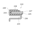
- 3A and 3B are schematic cross-sectional views of a part of the cylindrical battery 210 illustrating a method of forming the shoulder portion 238 in the cylindrical battery 210 of a comparative example, and FIGS.
- FIG. 2 is a schematic cross-sectional view of a portion of the cylindrical battery 10 for explaining the winding and tightening process.
- the cylindrical battery 210 has a groove 234 that is annularly recessed in the radial direction in the outer can 216.
- An annular protrusion 236 is provided that protrudes in both directions.
- the shoulder 238 (see FIG. 3B) of the cylindrical cell 210 is formed as follows. First, as shown in FIG. 3A, a laminated structure of a terminal cap 227 and a rupture plate 225, which constitute the peripheral edge of the sealing body 217, is placed above the annular protrusion 236 in the outer can 216 in the axial direction, with the gasket 228 interposed therebetween. .
- the upper end 216a of the outer can 216 is caulked and bent inward toward the peripheral edge 245 of the sealing body 217 as indicated by arrow A.
- the shoulder 238 of the cylindrical battery 210 shown in FIG. 3B is formed, and the peripheral edge 245 of the sealing body 217 is sandwiched between the shoulder 238 and the annular protrusion 236 via the gasket 228 to form an outer can.
- the opening of 216 is sealed.
- the rolling fixing structure 80 is formed as follows. First, as shown in FIG. 4A, the radially outward end of the washer 23, which is expanding in the radial direction, is folded back axially upward to form the cylindrical portion 51 on the radially outward side of the washer 23. Next, the cylindrical portion 51 is fitted into the cylindrical portion 43 of the outer can 16 by press fitting or the like, so that the cylindrical outer circumferential surface of the cylindrical portion 51 is brought into contact with the cylindrical inner circumferential surface of the cylindrical portion 43 of the outer can 16. Thereafter, in the direction shown by arrow B, the radially doubled cylindrical portion is rolled back 360 degrees or more inward in the radial direction, thereby forming the rolled-back fixing structure 80 shown in FIG. 4B.
- the rolled-up fixing structure 80 is formed by rolling back the radially doubled cylindrical portion 360 degrees or more inward in the radial direction. There is no need to rewind more than once.
- FIG. 4C that is, a schematic cross-sectional view corresponding to FIG. 4B of the modified cylindrical battery 110
- the radially inner side of the double-overlapping cylindrical portion is replaced with the rolled-up portion of the outer can 116.
- 145 may have a substantially U-shaped cross section
- the winding portion 131 of the washer 123 may have a substantially U-shaped cross section. In this way, the outer can 116 and the washer 123 may be sealed and fixed using double seaming, which is used for sealing canned goods.
- the rolled-up portion 45 of the outer can 16 has a first flat portion 83 at its axial tip that extends in an orthogonal direction substantially perpendicular to the axial direction.
- the terminal cap 27 has a second flat portion 85 at the tip in the axial direction that extends in an orthogonal direction substantially perpendicular to the axial direction.
- the axial position of the first flat part 83 is substantially the same as the axial position of the second flat part 85.
- Gasket 28 is an annular member.
- Gasket 28 includes a housing portion 28 a that is housed in annular groove 32 of washer 23 .
- Gasket 28 has an annular groove 39 that opens radially inward. The annular groove 39 accommodates the outer edge of the terminal cap 27 on the radially outer side.
- the gasket 28 is sandwiched between the washer 23 and the terminal cap 27 and insulates the terminal cap 27 from the washer 23.
- the gasket 28 has the role of a sealing material for maintaining airtightness inside the battery and the role of an insulating material for insulating the terminal cap 27 and the washer 23.
- a circular thin wall portion 71 centered on the radial center of the bottom plate portion 68 is provided on the bottom surface 68a of the bottom plate portion 68 of the outer can 16.
- the thin portion 71 constitutes an easily breakable portion.
- a portion of the bottom plate portion 68 surrounded by the circular thin wall portion 71 constitutes a safety valve 72 .
- the thin portion 71 is broken. In this way, an opening is formed at the location where the safety valve 72 is present, and the high temperature gas inside the battery is discharged to the outside.
- the easy-to-break part is formed by the circular thin-walled part 71, but the easily-breakable part may also be formed by, for example, providing a C-shaped thin-walled part on the bottom side of the bottom plate part. good.
- the easily breakable portion is not limited to a circular or C-shaped shape as long as an opening can be formed at the location where the safety valve 72 is present.
- a cylindrical battery shown in FIG. 1 was manufactured.
- a gasket was attached to the terminal cap, and the gasket was caulked and crimped to a washer to produce a sealing body.
- An electrode body was prepared using a positive electrode, a negative electrode, a separator, a positive electrode lead, and a negative electrode lead, and the electrode body was inserted into an outer can. No grooving was performed on the outer can. Electrolyte was poured into the outer can. Thereafter, the outer edges of the outer can and the sealing body were rolled and caulked, and the opening of the outer can was sealed with the sealing body, thereby producing a cylindrical lithium ion battery.
- a cylindrical battery shown in FIG. 5B was produced.
- An electrode body 214 was prepared using a positive electrode, a negative electrode, a separator, a positive electrode lead, and a negative electrode lead, and the electrode body 214 was inserted into an exterior can 216.
- the bottom plate portion of the outer can 216 and the negative electrode lead were welded to form the grooved portion 234.
- a gasket 228 was inserted, the positive electrode lead and the sealing body 217 were welded, and then an electrolytic solution was poured into the outer can 216.
- the upper end of the outer can 216 was bent radially inward by caulking to form a shoulder 238, and the opening of the outer can 216 was sealed with a sealing body 217, thereby producing a cylindrical lithium ion battery.
- the sealing body 217 was produced by welding the terminal cap 227, the rupture plate 225, and the terminal plate 229.
- Table 1 shows the ratio of each structure to the total battery length in the cylindrical battery 10 of the example and the cylindrical battery 210 of the comparative example. Further, FIG. 5A shows the breakdown of the battery height of each part in the cylindrical battery 10 of the example, and FIG. 5B shows the breakdown of the battery height of each part of the cylindrical battery 210 of the comparative example. As shown in FIGS. 5A, 5B, and Table 1, the structure of the sealing body 17 in the cylindrical battery 10 of the example is simpler than the structure of the sealing body 217 of the cylindrical battery 210 of the comparative example. Therefore, the thickness of the sealing body 17 can be reduced by 1.0% of the total battery length compared to the sealing body 217 of the comparative example.
- the cylindrical battery 10 of the example does not have the grooved portion 234, so that an additional 2.4% of the total length of the battery can be used to accommodate the electrode body 14. Accordingly, the axial height of the electrode body 14 could be increased by 3.4% of the total battery length compared to the electrode body 214 of the comparative example, and as a result, the battery capacity could be significantly increased.
- a battery pack with large output and capacity is sometimes produced by electrically connecting multiple cylindrical batteries.
- lead tabs are welded to the positive and negative electrodes of the battery, but for ease of welding, lead tabs are usually welded to the top of the sealing body (positive electrode) and the bottom of the can (negative electrode). conduct electricity.
- current can be collected by welding a lead tab to the top surface (positive electrode) of the sealing body and the shoulder (negative electrode) of the battery.
- FIG. 6 that is, an enlarged sectional view of the vicinity of the shoulder 238 of the cylindrical battery 210 of the reference example, in the cylindrical battery 210, since the gasket 228 is present near the shoulder 238, the shoulder If an attempt is made to laser weld the lead tab 290 for negative electrode connection to the gasket 238, there is a risk that the gasket 228 will melt due to the influence of heat, making it impossible to maintain good sealing performance. Furthermore, the height positions of the top surface 217a of the sealing body 217 and the top surface 238a of the shoulder portion 238 in the axial direction are different, making it difficult to perform laser welding of the lead tab 290 and the lead tab 291 for positive electrode connection.
- FIG. 7 that is, an enlarged cross-sectional view of the cylindrical battery 10 of the embodiment corresponding to FIG.
- the sealing performance is not affected. Therefore, a lead tab 290 for negative electrode connection can be welded near this end.
- the axial position of the first flat part 83 located at the tip of the rolled-up part 45 of the outer can 16 is the same as the axial position of the second flat part 85 located at the tip of the terminal cap 27. The location is almost the same. Therefore, laser welding of the pair of lead tabs 290 for negative electrode connection and lead tabs 291 for positive electrode connection can be easily performed, and the productivity of the battery pack can be greatly improved.
- the present inventor actually performed laser welding of the lead tab 290 described in FIGS. 6 and 7 and the lead tab 291 for positive electrode connection on 10 samples, and visually confirmed the thermal effect after welding. Specifically, the cylindrical battery 210 of the comparative example was subjected to a destructive inspection after welding, and the presence or absence of melting of the gasket 228 was visually confirmed. Table 2 shows the results.
- both the lead tab 290 for negative electrode connection and the lead tab 291 for positive electrode connection can be laser welded to the upper side of the battery in the axial direction, and the productivity of the battery pack can be greatly improved.
- 10,110 cylindrical battery 11 positive electrode, 12 negative electrode, 13 separator, 14 electrode body, 16,116 outer can, 17 sealing body, 18 upper insulating plate, 19 lower insulating plate, 20 positive electrode lead, 21 negative electrode lead, 23, 123 washer (first metal member), 27 terminal cap (second metal member), 28 gasket (insulating member), 28a accommodating section, 31,131 washer winding part (second winding part), 32 washer annular groove, 39 Annular groove of gasket, 42 Corner part, 43 Cylindrical part, 45,145 Rewinding part of outer can (first rewinding part), 68 Bottom plate part, 68a Bottom surface, 71 Thin wall part, 72 Safety valve, 80 Rewinding fixing structure, 83 No. 1 plane part, 85 2nd plane part.
Abstract
A cylindrical battery (10) comprises an outer case can (16), an electrode body (14) that is accommodated in the outer case can (16), and a sealing body (17) that covers an opening of the outer case can (16). The outer case can (16) comprises: a bottom plate portion (68); a cylinder portion (43) that is connected to the bottom plate portion (68) via an annular corner portion (42) that is positioned outward in the radial direction, and extends in the axial direction; and a rolled-back portion (45) that is connected to an end portion of the cylinder portion (43) that is on the opposite side from the corner portion (42) in the axial direction. The sealing body (17) comprises a rolled-back portion (31) that has an end portion on the outside in the radial direction, the end portion being secured to the rolled-back portion (45).
Description
本開示は、円筒形電池に関する。
The present disclosure relates to cylindrical batteries.
従来、円筒形電池としては、特許文献1の第3図に記載されているものがある。この円筒形電池は、外装缶と、外装缶内に収容される電極体と、外装缶の開口部を塞ぐ封口体を備える。封口体は、ガスケットを介して外装缶の開口部にかしめ固定される。外装缶は、肩部、溝入れ部、筒状部、及び底板部を有する。溝入れ部は、外装缶の側面の一部を、径方向内側に環状に窪ませることで形成される。封口体は、溝入れ部の形成によって径方向内方側に突出する環状突出部からガスケットを介して軸方向の開口部側の力を受ける。肩部は、封口体を外装缶にかしめ固定する際に、外装缶の上端部を封口体の周縁部に向かって内側に折り曲げることで形成される。
Conventionally, as a cylindrical battery, there is one described in FIG. 3 of Patent Document 1. This cylindrical battery includes an outer can, an electrode body housed in the outer can, and a sealing body that closes an opening of the outer can. The sealing body is caulked and fixed to the opening of the outer can via a gasket. The outer can has a shoulder portion, a grooved portion, a cylindrical portion, and a bottom plate portion. The grooved portion is formed by recessing a part of the side surface of the outer can in an annular shape radially inward. The sealing body receives a force on the opening side in the axial direction from the annular protrusion that protrudes radially inward through the gasket due to the formation of the grooved portion. The shoulder portion is formed by bending the upper end of the outer can inward toward the peripheral edge of the closure when caulking and fixing the closure to the outer can.
上記円筒形電池では、外装缶が溝入れ部を有するので、外装缶における電極体の収容部が、円筒形電池の高さ方向(軸方向)に関して溝入れ部よりも外装缶の底板部側に制限される。よって、電極体の収容部を大きくしにくく、電池容量を大きくしにくい。そこで、本開示の目的は、電極体の収容部を大きくでき、電池容量を大きくできる円筒形電池を提供することにある。
In the above-mentioned cylindrical battery, since the outer can has the grooved part, the electrode body housing part in the outer can is located closer to the bottom plate of the outer can than the grooved part in the height direction (axial direction) of the cylindrical battery. limited. Therefore, it is difficult to enlarge the housing portion of the electrode body, and it is difficult to increase the battery capacity. Therefore, an object of the present disclosure is to provide a cylindrical battery that can have a large housing part for an electrode body and can increase battery capacity.
上記課題を解決するため、本開示に係る円筒形電池は、外装缶と、外装缶内に収容される電極体と、外装缶の開口部を塞ぐ封口体と、を備え、外装缶が、底板部と、底板部に径方向の外方側に位置する環状の角部を介して連なると共に、軸方向に延在する円筒部と、円筒部における軸方向の角部側とは反対側の端部に繋がる第1巻き返し部と、を有し、封口体は、径方向の外方側の端部が第1巻き返し部に固定される第2巻き返し部を有する。
In order to solve the above problems, a cylindrical battery according to the present disclosure includes an outer can, an electrode body housed in the outer can, and a sealing body that closes an opening of the outer can, and the outer can has a bottom plate. a cylindrical part that extends in the axial direction and is connected to the bottom plate part via an annular corner located on the outer side in the radial direction; and an end of the cylindrical part on the opposite side from the corner in the axial direction. The sealing body has a second rolled-up part whose radially outer end is fixed to the first rolled-up part.
本開示に係る円筒形電池によれば、電極体の収容部を大きくでき、電池容量を大きくできる。
According to the cylindrical battery according to the present disclosure, the accommodating portion of the electrode body can be enlarged, and the battery capacity can be increased.
以下、図面を参照しながら、本開示に係る円筒形電池の実施形態について詳細に説明する。なお、本開示の円筒形電池は、一次電池でもよく、二次電池でもよい。また、水系電解質を用いた電池でもよく、非水系電解質を用いた電池でもよい。以下では、一実施形態である円筒形電池10として、非水電解質を用いた非水電解質二次電池(リチウムイオン電池)を例示するが、本開示の円筒形電池はこれに限定されない。
Hereinafter, embodiments of the cylindrical battery according to the present disclosure will be described in detail with reference to the drawings. Note that the cylindrical battery of the present disclosure may be a primary battery or a secondary battery. Further, a battery using an aqueous electrolyte or a non-aqueous electrolyte may be used. In the following, a non-aqueous electrolyte secondary battery (lithium ion battery) using a non-aqueous electrolyte will be exemplified as the cylindrical battery 10 that is one embodiment, but the cylindrical battery of the present disclosure is not limited to this.
以下で説明する実施形態や変形例の特徴部分を適宜に組み合わせて新たな実施形態を構築することは当初から想定されている。以下の実施形態では、図面において同一構成に同一符号を付し、重複する説明を省略する。また、複数の図面には、模式図が含まれ、異なる図間において、各部材における、縦、横、高さ等の寸法比は、必ずしも一致しない。本明細書では、円筒形電池10の軸方向(高さ方向)の封口体17側を「上」とし、軸方向の外装缶16の底板部68側を「下」とする。また、以下で説明される構成要素のうち、最上位概念を示す独立請求項に記載されていない構成要素については、任意の構成要素であり、必須の構成要素ではない。また、本開示は、下記実施形態およびその変形例に限定されるものではなく、本願の特許請求の範囲に記載された事項およびその均等な範囲において種々の改良や変更が可能である。
It has been envisioned from the beginning that a new embodiment will be constructed by appropriately combining the characteristic parts of the embodiments and modifications described below. In the following embodiments, the same components are denoted by the same reference numerals in the drawings, and overlapping explanations will be omitted. Furthermore, the plurality of drawings include schematic diagrams, and the dimensional ratios of each member, such as length, width, and height, do not necessarily match between different drawings. In this specification, the axial direction (height direction) side of the sealing body 17 of the cylindrical battery 10 is referred to as the "upper", and the axial direction of the bottom plate portion 68 of the outer can 16 is referred to as the "lower". Furthermore, among the constituent elements described below, constituent elements that are not described in the independent claim indicating the most significant concept are optional constituent elements and are not essential constituent elements. Further, the present disclosure is not limited to the following embodiments and modifications thereof, and various improvements and changes can be made within the scope of the claims of the present application and equivalents thereof.
図1は、本開示の一実施形態に係る円筒形電池10の軸方向の断面図であり、図2は、円筒形電池10の電極体14の斜視図である。図1に示すように、円筒形電池10は、巻回型の電極体14、非水電解質(図示せず)、電極体14及び非水電解質を収容する有底筒状で金属製の外装缶16、及び外装缶16の開口部を塞ぐ封口体17を備える。図2に示すように、電極体14は、長尺状の正極11と長尺状の負極12が長尺状の2枚のセパレータ13を介して巻回された巻回構造を有する。
FIG. 1 is an axial cross-sectional view of a cylindrical battery 10 according to an embodiment of the present disclosure, and FIG. 2 is a perspective view of an electrode body 14 of the cylindrical battery 10. As shown in FIG. 1, the cylindrical battery 10 includes a wound electrode body 14, a nonaqueous electrolyte (not shown), and a bottomed cylindrical metal outer can that houses the electrode body 14 and the nonaqueous electrolyte. 16, and a sealing body 17 that closes the opening of the outer can 16. As shown in FIG. 2, the electrode body 14 has a wound structure in which an elongated positive electrode 11 and an elongated negative electrode 12 are wound with two elongated separators 13 in between.
負極12は、リチウムの析出を防止するために、正極11よりも一回り大きな寸法で形成される。即ち、負極12は、正極11より長手方向及び幅方向(短手方向)に長く形成される。また、2枚のセパレータ13は、少なくとも正極11よりも一回り大きな寸法で形成され、例えば正極11を挟むように配置される。負極12は、電極体14の巻き始め端を構成してもよい。しかし、一般的には、セパレータ13が負極12の巻き始め側端を超えて延出し、セパレータ13の巻き始め側端が電極体14の巻き始め端となる。
The negative electrode 12 is formed to be one size larger than the positive electrode 11 in order to prevent precipitation of lithium. That is, the negative electrode 12 is formed longer than the positive electrode 11 in the longitudinal direction and the width direction (short direction). Further, the two separators 13 are formed to be at least one size larger than the positive electrode 11, and are arranged to sandwich the positive electrode 11, for example. The negative electrode 12 may constitute the winding start end of the electrode body 14. However, in general, the separator 13 extends beyond the winding start side end of the negative electrode 12, and the winding start side end of the separator 13 becomes the winding start end of the electrode body 14.
非水電解質は、非水溶媒と、非水溶媒に溶解した電解質塩とを含む。非水溶媒には、例えばエステル類、エーテル類、ニトリル類、アミド類、およびこれらの2種以上の混合溶媒等を用いてもよい。非水溶媒は、これら溶媒の水素原子の少なくとも一部をフッ素等のハロゲン原子で置換したハロゲン置換体を含有してもよい。なお、非水電解質は液体電解質に限定されず、ゲル状ポリマー等を用いた固体電解質であってもよい。電解質塩には、LiPF6等のリチウム塩が使用される。
The non-aqueous electrolyte includes a non-aqueous solvent and an electrolyte salt dissolved in the non-aqueous solvent. As the non-aqueous solvent, for example, esters, ethers, nitriles, amides, and mixed solvents of two or more of these may be used. The non-aqueous solvent may contain a halogen-substituted product in which at least a portion of the hydrogen atoms of these solvents are replaced with halogen atoms such as fluorine. Note that the non-aqueous electrolyte is not limited to a liquid electrolyte, and may be a solid electrolyte using a gel-like polymer or the like. A lithium salt such as LiPF 6 is used as the electrolyte salt.
正極11は、正極集電体と、正極集電体の両面に形成された正極合剤層とを有する。正極集電体には、アルミニウム、アルミニウム合金など、正極11の電位範囲で安定な金属箔、当該金属を表層に配置したフィルム等を用いることができる。正極合剤層は、正極活物質、導電剤、及び結着剤を含む。正極11は、例えば正極集電体上に正極活物質、導電剤、及び結着剤等を含む正極合剤スラリーを塗布し、塗膜を乾燥させた後、圧縮して正極
合剤層を集電体の両面に形成することにより作製できる。 Thepositive electrode 11 includes a positive electrode current collector and positive electrode mixture layers formed on both sides of the positive electrode current collector. For the positive electrode current collector, a metal foil such as aluminum or an aluminum alloy that is stable in the potential range of the positive electrode 11, a film having the metal disposed on the surface layer, or the like can be used. The positive electrode mixture layer includes a positive electrode active material, a conductive agent, and a binder. The positive electrode 11 is made by, for example, applying a positive electrode mixture slurry containing a positive electrode active material, a conductive agent, a binder, etc. onto a positive electrode current collector, drying the coating film, and then compressing it to collect the positive electrode mixture layer. It can be produced by forming on both sides of the electric body.
合剤層を集電体の両面に形成することにより作製できる。 The
正極活物質は、リチウム含有金属複合酸化物を主成分として構成される。リチウム含有金属複合酸化物に含有される金属元素としては、Ni、Co、Mn、Al、B、Mg、Ti、V、Cr、Fe、Cu、Zn、Ga、Sr、Zr、Nb、In、Sn、Ta、W等が挙げられる。好ましいリチウム含有金属複合酸化物の一例は、Ni、Co、Mn、Alの少なくとも1種を含有する複合酸化物である。
The positive electrode active material is composed of a lithium-containing metal composite oxide as a main component. Metal elements contained in the lithium-containing metal composite oxide include Ni, Co, Mn, Al, B, Mg, Ti, V, Cr, Fe, Cu, Zn, Ga, Sr, Zr, Nb, In, and Sn. , Ta, W, etc. An example of a preferable lithium-containing metal composite oxide is a composite oxide containing at least one of Ni, Co, Mn, and Al.
正極合剤層に含まれる導電剤としては、カーボンブラック、アセチレンブラック、ケッチェンブラック、黒鉛等の炭素材料が例示できる。正極合剤層に含まれる結着剤としては、ポリテトラフルオロエチレン(PTFE)、ポリフッ化ビニリデン(PVdF)等のフッ素樹脂、ポリアクリロニトリル(PAN)、ポリイミド樹脂、アクリル樹脂、ポリオレフィン樹脂などが例示できる。これらの樹脂と、カルボキシメチルセルロース(CMC)又はその塩等のセルロース誘導体、ポリエチレンオキシド(PEO)などが併用されてもよい。
Examples of the conductive agent contained in the positive electrode mixture layer include carbon materials such as carbon black, acetylene black, Ketjen black, and graphite. Examples of the binder included in the positive electrode mixture layer include fluororesins such as polytetrafluoroethylene (PTFE) and polyvinylidene fluoride (PVdF), polyacrylonitrile (PAN), polyimide resins, acrylic resins, and polyolefin resins. . These resins may be used in combination with cellulose derivatives such as carboxymethyl cellulose (CMC) or its salts, polyethylene oxide (PEO), and the like.
負極12は、負極集電体と、負極集電体の両面に形成された負極合剤層を有する。負極集電体には、銅、銅合金など、負極12の電位範囲で安定な金属箔、当該金属を表層に配置したフィルム等を用いることができる。負極合剤層は、負極活物質、及び結着剤を含む。負極12は、例えば負極集電体上に負極活物質、及び結着剤等を含む負極合剤スラリーを塗布し、塗膜を乾燥させた後、圧縮して負極合剤層を集電体の両面に形成することにより作製できる。
The negative electrode 12 has a negative electrode current collector and negative electrode mixture layers formed on both sides of the negative electrode current collector. For the negative electrode current collector, a metal foil such as copper or a copper alloy that is stable in the potential range of the negative electrode 12, a film with the metal disposed on the surface, or the like can be used. The negative electrode mixture layer includes a negative electrode active material and a binder. For example, the negative electrode 12 can be made by applying a negative electrode mixture slurry containing a negative electrode active material, a binder, etc. onto a negative electrode current collector, drying the coating film, and then compressing the negative electrode mixture layer to form a negative electrode mixture layer on the current collector. It can be produced by forming on both sides.
負極活物質には、一般的に、リチウムイオンを可逆的に吸蔵、放出する炭素材料が用いられる。好ましい炭素材料は、鱗片状黒鉛、塊状黒鉛、土状黒鉛等の天然黒鉛、塊状人造黒鉛、黒鉛化メソフェーズカーボンマイクロビーズ等の人造黒鉛などの黒鉛である。負極合剤層には、負極活物質として、ケイ素(Si)を含有するSi材料が含まれていてもよい。また、負極活物質には、Si以外のリチウムと合金化する金属、当該金属を含有する合金、当該金属を含有する化合物等が用いられてもよい。
A carbon material that reversibly occludes and releases lithium ions is generally used as the negative electrode active material. Preferred carbon materials include natural graphite such as flaky graphite, lumpy graphite, and earthy graphite, and graphite such as artificial graphite such as lumpy artificial graphite and graphitized mesophase carbon microbeads. The negative electrode mixture layer may contain a Si material containing silicon (Si) as a negative electrode active material. Furthermore, a metal other than Si that is alloyed with lithium, an alloy containing the metal, a compound containing the metal, etc. may be used as the negative electrode active material.
負極合剤層に含まれる結着剤には、正極11の場合と同様に、フッ素樹脂、PAN、ポリイミド樹脂、アクリル樹脂、ポリオレフィン樹脂等を用いてもよいが、好ましくはスチレン-ブタジエンゴム(SBR)又はその変性体を用いる。負極合剤層には、例えばSBR等に加えて、CMC又はその塩、ポリアクリル酸(PAA)又はその塩、ポリビニルアルコールなどが含まれていてもよい。
As in the case of the positive electrode 11, the binder contained in the negative electrode mixture layer may be a fluororesin, PAN, polyimide resin, acrylic resin, polyolefin resin, etc., but preferably styrene-butadiene rubber (SBR). ) or its modified form. The negative electrode mixture layer may contain, for example, in addition to SBR or the like, CMC or a salt thereof, polyacrylic acid (PAA) or a salt thereof, polyvinyl alcohol, or the like.
セパレータ13には、イオン透過性及び絶縁性を有する多孔性シートが用いられる。多孔性シートの具体例としては、微多孔薄膜、織布、不織布等が挙げられる。セパレータ13の材質としては、ポリエチレン、ポリプロピレン等のポリオレフィン樹脂、セルロースなどが好ましい。セパレータ13は、単層構造、積層構造のいずれでもよい。セパレータ13の表面には、耐熱層などが形成されてもよい。
A porous sheet having ion permeability and insulation properties is used for the separator 13. Specific examples of porous sheets include microporous thin films, woven fabrics, and nonwoven fabrics. Preferable materials for the separator 13 include polyolefin resins such as polyethylene and polypropylene, cellulose, and the like. The separator 13 may have either a single layer structure or a laminated structure. A heat-resistant layer or the like may be formed on the surface of the separator 13.
図1に示すように、正極11には、正極リード20が接合され、負極12の長手方向の巻き終わり側端部には、負極リード21が接合される。円筒形電池10は、電極体14の上方に上部絶縁板18を有し、電極体14の下方に下部絶縁板19を有する。正極リード20は、上部絶縁板18の貫通孔を通って封口体17側に延び、負極リード21は、下部絶縁板19の外側を通って外装缶16の底板部68側に延びる。正極リード20は、封口体17の端子キャップ27の下面に溶接等で接続され、端子キャップ27が正極端子となる。また、負極リード21は、金属製の外装缶16の底板部68の内面に溶接等で接続され、外装缶16が負極端子となる。
As shown in FIG. 1, a positive electrode lead 20 is bonded to the positive electrode 11, and a negative electrode lead 21 is bonded to the end of the negative electrode 12 at the winding end in the longitudinal direction. The cylindrical battery 10 has an upper insulating plate 18 above the electrode body 14 and a lower insulating plate 19 below the electrode body 14. The positive electrode lead 20 extends to the sealing body 17 side through the through hole of the upper insulating plate 18 , and the negative electrode lead 21 extends to the bottom plate portion 68 side of the outer can 16 through the outside of the lower insulating plate 19 . The positive electrode lead 20 is connected to the lower surface of the terminal cap 27 of the sealing body 17 by welding or the like, and the terminal cap 27 serves as a positive electrode terminal. Further, the negative electrode lead 21 is connected to the inner surface of the bottom plate portion 68 of the metal outer can 16 by welding or the like, and the outer can 16 serves as a negative electrode terminal.
図1及び図2に示す例では、正極リード20は、正極集電体における巻回方向の中央部等の中間部に電気的に接続され、負極リード21は、負極集電体における巻回方向の巻き終わり側端部に電気的に接続される。しかし、負極リードは、負極集電体における巻回方向の巻き始め側端部に電気的に接続されてもよい。又は、電極体が2つの負極リードを有して、一方の負極リードが、負極集電体における巻回方向の巻き始め側端部に電気的に接続され、他方の負極リードが、負極集電体における巻回方向の巻き終わり側端部に電気的に接続されてもよい。又は、負極集電体における巻回方向の巻き終わり側端部を外装缶の内面に当接させることで、負極と外装缶を電気的に接続してもよい。又は、負極リードを、負極集電体における巻回方向の巻き始め側端部に電気的に接続し、負極集電体における巻回方向の巻き終わり側端部を外装缶の内面に当接させてもよい。
In the example shown in FIGS. 1 and 2, the positive electrode lead 20 is electrically connected to an intermediate portion such as the center in the winding direction of the positive electrode current collector, and the negative electrode lead 21 is electrically connected to an intermediate portion in the winding direction of the negative electrode current collector. It is electrically connected to the end of the winding end. However, the negative electrode lead may be electrically connected to the winding start side end of the negative electrode current collector in the winding direction. Alternatively, the electrode body has two negative electrode leads, one negative electrode lead is electrically connected to the winding start side end of the negative electrode current collector in the winding direction, and the other negative electrode lead is connected to the negative electrode current collector. It may be electrically connected to the winding end side end in the winding direction of the body. Alternatively, the negative electrode and the outer can may be electrically connected by bringing the end portion of the negative electrode current collector in the winding direction into contact with the inner surface of the outer can. Alternatively, the negative electrode lead is electrically connected to the winding start side end of the negative electrode current collector in the winding direction, and the winding end side end of the negative electrode current collector in the winding direction is brought into contact with the inner surface of the outer can. It's okay.
外装缶16は、底板部68と、底板部68の径方向の外方側の端部につながって軸方向上側に屈曲する環状の角部42と、角部42における底板部68側と反対側から軸方向上側に延在する円筒形状の円筒部43と、円筒部43の軸方向の上側端部に繋がる巻き返し部45と、を有する。また、封口体17は、環状の第1金属部材を構成するワッシャ23と、絶縁性を有する環状のガスケット28と、端子キャップ27を有する。ガスケット28は、絶縁部材を構成し、端子キャップ27は、第2金属部材を構成する。ワッシャ23は、径方向の外方側の端部に巻き返し部31を有すると共に、径方向の内方側の端部に径方向の内方側に開口する環状溝32を有する。ワッシャ23の巻き返し部31は、外装缶16の巻き返し部45に固定される。
The outer can 16 includes a bottom plate portion 68, an annular corner portion 42 connected to the radially outer end of the bottom plate portion 68 and bent upward in the axial direction, and a side of the corner portion 42 opposite to the bottom plate portion 68 side. It has a cylindrical portion 43 having a cylindrical shape extending upward in the axial direction from the cylindrical portion 43, and a rolled-back portion 45 connected to the upper end of the cylindrical portion 43 in the axial direction. Further, the sealing body 17 includes a washer 23 that constitutes a first annular metal member, an annular gasket 28 having insulation properties, and a terminal cap 27 . Gasket 28 constitutes an insulating member, and terminal cap 27 constitutes a second metal member. The washer 23 has a turned-up portion 31 at its radially outer end, and has an annular groove 32 that opens radially inward at its radially inner end. The rolled portion 31 of the washer 23 is fixed to the rolled portion 45 of the outer can 16.
詳しくは、外装缶16の巻き返し部45とワッシャ23の巻き返し部31の巻き返し固定構造80は、巻き返しかしめにより形成され、外装缶16の巻き返し部45とワッシャ23の巻き返し部31は、巻き返しかしめにより同時に形成される。図3A及び図3Bは、比較例の円筒形電池210における肩部238の形成方法を説明する円筒形電池210の一部の模式断面図であり、図4A及び図4Bは、円筒形電池10の巻き返しかしめについて説明する円筒形電池10の一部の模式断面図である。
Specifically, the rolled-up fixing structure 80 of the rolled-up part 45 of the outer can 16 and the rolled-up part 31 of the washer 23 is formed by rolled-up clinching, and the rolled-up part 45 of the outer can 16 and the rolled-up part 31 of the washer 23 are simultaneously fixed by rolled-up clinching. It is formed. 3A and 3B are schematic cross-sectional views of a part of the cylindrical battery 210 illustrating a method of forming the shoulder portion 238 in the cylindrical battery 210 of a comparative example, and FIGS. FIG. 2 is a schematic cross-sectional view of a portion of the cylindrical battery 10 for explaining the winding and tightening process.
図3A及び図3Bに示すように、円筒形電池210は、外装缶216に径方向内側に環状に窪ませた溝入れ部234を有し、これにより、円筒形電池210には、径方向内方側に突出する環状突出部236が設けられる。円筒形電池210の肩部238(図3B参照)は次のように形成される。先ず、図3Aに示すように、外装缶216における環状突出部236の軸方向上側に、ガスケット228を介して封口体217の周縁部を構成する端子キャップ227とラプチャー板225の積層構造を配置する。その後、外装缶216の上端部216aを矢印Aで示す封口体217の周縁部245に向かって内側にかしめて折り曲げる。このようにして、図3Bに示す、円筒形電池210の肩部238を形成すると共に、肩部238と環状突出部236でガスケット228を介して封口体217の周縁部245を挟持して外装缶216の開口部を封口する。
As shown in FIGS. 3A and 3B, the cylindrical battery 210 has a groove 234 that is annularly recessed in the radial direction in the outer can 216. An annular protrusion 236 is provided that protrudes in both directions. The shoulder 238 (see FIG. 3B) of the cylindrical cell 210 is formed as follows. First, as shown in FIG. 3A, a laminated structure of a terminal cap 227 and a rupture plate 225, which constitute the peripheral edge of the sealing body 217, is placed above the annular protrusion 236 in the outer can 216 in the axial direction, with the gasket 228 interposed therebetween. . Thereafter, the upper end 216a of the outer can 216 is caulked and bent inward toward the peripheral edge 245 of the sealing body 217 as indicated by arrow A. In this way, the shoulder 238 of the cylindrical battery 210 shown in FIG. 3B is formed, and the peripheral edge 245 of the sealing body 217 is sandwiched between the shoulder 238 and the annular protrusion 236 via the gasket 228 to form an outer can. The opening of 216 is sealed.
これに対し、円筒形電池10では、次のように巻き返し固定構造80を形成する。先ず、図4Aに示すように、径方向に広がっているワッシャ23の径方向外方側の端部を軸方向上側に折り返して、ワッシャ23の径方向外方側に円筒部51を形成する。次に、円筒部51を圧入等により外装缶16の円筒部43に内嵌することで、円筒部51の円筒外周面を外装缶16の円筒部43の円筒内周面に当接させる。その後、矢印Bに示す方向に、径方向に2重に重なった円筒部を径方向内側に360度以上巻き返すことで図4Bに示す巻き返し固定構造80を形成する。
On the other hand, in the cylindrical battery 10, the rolling fixing structure 80 is formed as follows. First, as shown in FIG. 4A, the radially outward end of the washer 23, which is expanding in the radial direction, is folded back axially upward to form the cylindrical portion 51 on the radially outward side of the washer 23. Next, the cylindrical portion 51 is fitted into the cylindrical portion 43 of the outer can 16 by press fitting or the like, so that the cylindrical outer circumferential surface of the cylindrical portion 51 is brought into contact with the cylindrical inner circumferential surface of the cylindrical portion 43 of the outer can 16. Thereafter, in the direction shown by arrow B, the radially doubled cylindrical portion is rolled back 360 degrees or more inward in the radial direction, thereby forming the rolled-back fixing structure 80 shown in FIG. 4B.
なお、本実施形態では、径方向に2重に重なった円筒部を径方向内側に360度以上巻き返すことで、巻き返し固定構造80を形成したが、径方向に2重に重なった円筒部を360度以上巻き返さなくてもよい。詳しくは、図4C、すなわち、変形例の円筒形電池110における図4Bに対応する模式断面図に示すように、2重に重なった円筒部の径方向内側の巻き返しを、外装缶116の巻き返し部145が断面略U字状になると共に、ワッシャ123の巻き返し部131が断面略U字状になった状態で完了してもよい。このように、缶詰の密封等に用いられる2重巻締を用いて外装缶116とワッシャ123を密封固定してもよい。
In the present embodiment, the rolled-up fixing structure 80 is formed by rolling back the radially doubled cylindrical portion 360 degrees or more inward in the radial direction. There is no need to rewind more than once. Specifically, as shown in FIG. 4C, that is, a schematic cross-sectional view corresponding to FIG. 4B of the modified cylindrical battery 110, the radially inner side of the double-overlapping cylindrical portion is replaced with the rolled-up portion of the outer can 116. 145 may have a substantially U-shaped cross section, and the winding portion 131 of the washer 123 may have a substantially U-shaped cross section. In this way, the outer can 116 and the washer 123 may be sealed and fixed using double seaming, which is used for sealing canned goods.
再度、図1を参照して、外装缶16の巻き返し部45は、軸方向の先端に軸方向に略直交する直交方向に広がる第1平面部83を有する。また、端子キャップ27は、軸方向の先端に軸方向に略直交する直交方向に広がる第2平面部85を有する。第1平面部83の軸方向の位置は、第2平面部85の軸方向の位置と略同一になっている。ガスケット28は、環状部材である。ガスケット28は、ワッシャ23の環状溝32に収容される収容部28aを含む。ガスケット28は、径方向の内方側に開口する環状溝39を有する。環状溝39には、端子キャップ27の径方向外方側の外縁部が収容される。
Referring again to FIG. 1, the rolled-up portion 45 of the outer can 16 has a first flat portion 83 at its axial tip that extends in an orthogonal direction substantially perpendicular to the axial direction. Further, the terminal cap 27 has a second flat portion 85 at the tip in the axial direction that extends in an orthogonal direction substantially perpendicular to the axial direction. The axial position of the first flat part 83 is substantially the same as the axial position of the second flat part 85. Gasket 28 is an annular member. Gasket 28 includes a housing portion 28 a that is housed in annular groove 32 of washer 23 . Gasket 28 has an annular groove 39 that opens radially inward. The annular groove 39 accommodates the outer edge of the terminal cap 27 on the radially outer side.
ガスケット28は、ワッシャ23と端子キャップ27に挟持され、端子キャップ27をワッシャ23に対して絶縁する。ガスケット28は、電池内部の気密性を保つためのシール材の役割と、端子キャップ27とワッシャ23を絶縁する絶縁材としての役割を有する。円筒形電池10の作製時においては、端子キャップ27とガスケット28とワッシャ23を一体化して統合した後、図4A及び図4Bを用いて説明した巻き返しかしめを行うことで、外装缶16の開口部を密封する。
The gasket 28 is sandwiched between the washer 23 and the terminal cap 27 and insulates the terminal cap 27 from the washer 23. The gasket 28 has the role of a sealing material for maintaining airtightness inside the battery and the role of an insulating material for insulating the terminal cap 27 and the washer 23. When manufacturing the cylindrical battery 10, after integrating the terminal cap 27, gasket 28, and washer 23, the opening of the outer can 16 is closed by rolling back and clinching as described using FIGS. 4A and 4B. to be sealed.
外装缶16の底板部68の底面68aには、底板部68の径方向の中心を中心とする円形の薄肉部71が設けられている。薄肉部71は、易破断部を構成する。底板部68において円形の薄肉部71で囲まれた部分は、安全弁72を構成する。円筒形電池10が異常発熱したときに、薄肉部71を破断させるようになっている。このようにして、安全弁72の存在箇所に開口を形成し、電池内の高温のガスを外部に排出するようになっている。なお、本実施形態では、円形の薄肉部71で易破断部を構成する場合について説明したが、例えばC字形状の薄肉部を底板部の底側に設けることで易破断部を構成してもよい。易破断部は、安全弁72の存在箇所に開口を形成することができれば、円形やC字形状に限定されるものではない。
A circular thin wall portion 71 centered on the radial center of the bottom plate portion 68 is provided on the bottom surface 68a of the bottom plate portion 68 of the outer can 16. The thin portion 71 constitutes an easily breakable portion. A portion of the bottom plate portion 68 surrounded by the circular thin wall portion 71 constitutes a safety valve 72 . When the cylindrical battery 10 generates abnormal heat, the thin portion 71 is broken. In this way, an opening is formed at the location where the safety valve 72 is present, and the high temperature gas inside the battery is discharged to the outside. In this embodiment, a case has been described in which the easy-to-break part is formed by the circular thin-walled part 71, but the easily-breakable part may also be formed by, for example, providing a C-shaped thin-walled part on the bottom side of the bottom plate part. good. The easily breakable portion is not limited to a circular or C-shaped shape as long as an opening can be formed at the location where the safety valve 72 is present.
<実施例>
図1に示す円筒形電池を作製した。端子キャップにガスケットを装着し、ガスケットをワッシャーにカシメ圧着することで封口体を作製した。正極、負極、セパレータ、正極リード、負極リードを用いて電極体を作製し、電極体を外装缶内に挿入した。外装缶には溝入れ加工を実施しなかった。外装缶に電解液を注液した。その後、外装缶と封口体の外縁部を巻き回すかしめを行って、外装缶の開口部を封口体で封止することで、円筒形リチウムイオン電池を作製した。 <Example>
A cylindrical battery shown in FIG. 1 was manufactured. A gasket was attached to the terminal cap, and the gasket was caulked and crimped to a washer to produce a sealing body. An electrode body was prepared using a positive electrode, a negative electrode, a separator, a positive electrode lead, and a negative electrode lead, and the electrode body was inserted into an outer can. No grooving was performed on the outer can. Electrolyte was poured into the outer can. Thereafter, the outer edges of the outer can and the sealing body were rolled and caulked, and the opening of the outer can was sealed with the sealing body, thereby producing a cylindrical lithium ion battery.
<比較例>
図5Bに示す円筒形電池を作製した。正極、負極、セパレータ、正極リード、負極リードを用いて電極体214を作製し、電極体214を外装缶216内に挿入した。外装缶216の底板部と負極リードとを溶接し、溝入れ部234を形成した。ガスケット228を挿入し、正極リードと封口体217とを溶接し、その後、外装缶216に電解液を注液した。続いて、外装缶216の上側端部をかしめにより径方向内側に折り曲げて肩部238を形成することで、外装缶216の開口部を封口体217で密封し、円筒形リチウムイオン電池を作製した。封口体217は、端子キャップ227、ラプチャー板225、及び端子板229を溶接することで作製した。 <Comparative example>
A cylindrical battery shown in FIG. 5B was produced. Anelectrode body 214 was prepared using a positive electrode, a negative electrode, a separator, a positive electrode lead, and a negative electrode lead, and the electrode body 214 was inserted into an exterior can 216. The bottom plate portion of the outer can 216 and the negative electrode lead were welded to form the grooved portion 234. A gasket 228 was inserted, the positive electrode lead and the sealing body 217 were welded, and then an electrolytic solution was poured into the outer can 216. Subsequently, the upper end of the outer can 216 was bent radially inward by caulking to form a shoulder 238, and the opening of the outer can 216 was sealed with a sealing body 217, thereby producing a cylindrical lithium ion battery. . The sealing body 217 was produced by welding the terminal cap 227, the rupture plate 225, and the terminal plate 229.
図5Bに示す円筒形電池を作製した。正極、負極、セパレータ、正極リード、負極リードを用いて電極体214を作製し、電極体214を外装缶216内に挿入した。外装缶216の底板部と負極リードとを溶接し、溝入れ部234を形成した。ガスケット228を挿入し、正極リードと封口体217とを溶接し、その後、外装缶216に電解液を注液した。続いて、外装缶216の上側端部をかしめにより径方向内側に折り曲げて肩部238を形成することで、外装缶216の開口部を封口体217で密封し、円筒形リチウムイオン電池を作製した。封口体217は、端子キャップ227、ラプチャー板225、及び端子板229を溶接することで作製した。 <Comparative example>
A cylindrical battery shown in FIG. 5B was produced. An
[電池高さ内訳]

[Battery height breakdown]
表1に実施例の円筒形電池10と比較例の円筒形電池210における各構成の電池全長に対する割合を示す。また、図5Aに実施例の円筒形電池10における各部位の電池高さ内訳を示し、図5Bに比較例の円筒形電池210における各部位の電池高さ内訳を示す。図5A、図5B及び表1に示すように、実施例の円筒形電池10では、封口体17の構造が、比較例の円筒形電池210の封口体217の構造よりも単純な構造となっており、封口体17の厚さを比較例の封口体217との比較で、電池全長の1.0%低減できる。更に、実施例の円筒形電池10では、比較例の円筒形電池210と異なり、溝入れ部234が存在しないため、更に、電池全長の2.4%のスペースを電極体14の収容に用いることができ、その分、電極体14の軸方向高さを、比較例の電極体214との比較で、電池全長の3.4%高くでき、その結果、電池容量を格段に大きくできた。
Table 1 shows the ratio of each structure to the total battery length in the cylindrical battery 10 of the example and the cylindrical battery 210 of the comparative example. Further, FIG. 5A shows the breakdown of the battery height of each part in the cylindrical battery 10 of the example, and FIG. 5B shows the breakdown of the battery height of each part of the cylindrical battery 210 of the comparative example. As shown in FIGS. 5A, 5B, and Table 1, the structure of the sealing body 17 in the cylindrical battery 10 of the example is simpler than the structure of the sealing body 217 of the cylindrical battery 210 of the comparative example. Therefore, the thickness of the sealing body 17 can be reduced by 1.0% of the total battery length compared to the sealing body 217 of the comparative example. Furthermore, unlike the cylindrical battery 210 of the comparative example, the cylindrical battery 10 of the example does not have the grooved portion 234, so that an additional 2.4% of the total length of the battery can be used to accommodate the electrode body 14. Accordingly, the axial height of the electrode body 14 could be increased by 3.4% of the total battery length compared to the electrode body 214 of the comparative example, and as a result, the battery capacity could be significantly increased.
[電池パックを作製する際の優位性]
複数の円筒形電池を電気的に接続して出力や容量が大きな電池パックを作製することがある。電池パックを製造する際に、電池の正負極にリードタブを溶接するが、溶接し易さの観点により、通常は封口体の天面(正極)と缶底(負極)にリードタブを溶接して集電を行う。しかし、生産性向上の観点より、封口体の天面(正極)と電池の肩部(負極)とにリードタブを溶接することで集電できれば好ましい。 [Advantages when manufacturing battery packs]
A battery pack with large output and capacity is sometimes produced by electrically connecting multiple cylindrical batteries. When manufacturing battery packs, lead tabs are welded to the positive and negative electrodes of the battery, but for ease of welding, lead tabs are usually welded to the top of the sealing body (positive electrode) and the bottom of the can (negative electrode). conduct electricity. However, from the viewpoint of improving productivity, it is preferable if current can be collected by welding a lead tab to the top surface (positive electrode) of the sealing body and the shoulder (negative electrode) of the battery.
しかしながら、図6、すなわち、参考例の円筒形電池210の肩部238の周辺の拡大断面図に示すように、円筒形電池210では、肩部238の近傍にガスケット228が存在するため、肩部238に負極接続用のリードタブ290をレーザー溶接しようとすると、熱影響によりガスケット228が溶融して良好なシール性を保てなくなる虞がある。また、封口体217の天面217aと、肩部238の上面238aの軸方向の高さ位置が異なり、リードタブ290と正極接続用のリードタブ291のレーザー溶接を実施しにくい。
However, as shown in FIG. 6, that is, an enlarged sectional view of the vicinity of the shoulder 238 of the cylindrical battery 210 of the reference example, in the cylindrical battery 210, since the gasket 228 is present near the shoulder 238, the shoulder If an attempt is made to laser weld the lead tab 290 for negative electrode connection to the gasket 238, there is a risk that the gasket 228 will melt due to the influence of heat, making it impossible to maintain good sealing performance. Furthermore, the height positions of the top surface 217a of the sealing body 217 and the top surface 238a of the shoulder portion 238 in the axial direction are different, making it difficult to perform laser welding of the lead tab 290 and the lead tab 291 for positive electrode connection.
これに対し、図7、すなわち、実施例の円筒形電池10における図6に対応する拡大断面図に示すように、円筒形電池10では、外装缶16と封口体17を巻き返しかしめにより密封固定し、円筒形電池10の軸方向上側かつ径方向外方側の端部近傍にガスケットが存在しない。したがって、その端部近傍に熱が加わってもシール性に影響しない。したがって、この端部近傍に負極接続用のリードタブ290を溶接できる。更には、円筒形電池10では、外装缶16の巻き返し部45の先端に位置する第1平面部83の軸方向の位置が、端子キャップ27の先端に位置する第2平面部85の軸方向の位置と略同一になっている。よって、負極接続用のリードタブ290と正極接続用のリードタブ291の一対のレーザー溶接を実施し易くなり、電池パックの生産性を大きく向上できる。
On the other hand, as shown in FIG. 7, that is, an enlarged cross-sectional view of the cylindrical battery 10 of the embodiment corresponding to FIG. , there is no gasket near the axially upper and radially outer end of the cylindrical battery 10. Therefore, even if heat is applied near the end, the sealing performance is not affected. Therefore, a lead tab 290 for negative electrode connection can be welded near this end. Furthermore, in the cylindrical battery 10, the axial position of the first flat part 83 located at the tip of the rolled-up part 45 of the outer can 16 is the same as the axial position of the second flat part 85 located at the tip of the terminal cap 27. The location is almost the same. Therefore, laser welding of the pair of lead tabs 290 for negative electrode connection and lead tabs 291 for positive electrode connection can be easily performed, and the productivity of the battery pack can be greatly improved.
本発明者は、図6及び図7で説明したリードタブ290と正極接続用のリードタブ291のレーザー溶接を10個のサンプルに対して実際に行い、溶接後の熱影響を目視で確認した。詳しくは、比較例の円筒形電池210に関して溶接後に破壊検査を行って、ガスケット228の溶融の有無を目視で確認した。表2にその結果を示す。

The present inventor actually performed laser welding of the lead tab 290 described in FIGS. 6 and 7 and the lead tab 291 for positive electrode connection on 10 samples, and visually confirmed the thermal effect after welding. Specifically, the cylindrical battery 210 of the comparative example was subjected to a destructive inspection after welding, and the presence or absence of melting of the gasket 228 was visually confirmed. Table 2 shows the results.
比較例の円筒形電池210では、10個のサンプル全てでガスケットの溶融が確認でき、肩部にレーザー溶接を施すと、封止性と絶縁性に問題を生じる虞がありことを確認できた。一方、実施例の円筒形電池10では、全てのサンプルで封止性に問題が確認されなかった。よって、本開示の円筒形電池を作製すれば、負極接続用のリードタブ290と正極接続用のリードタブ291の両方を電池の軸方向上側にレーザー溶接でき、電池パックの生産性を大きく向上できる。
In the cylindrical battery 210 of the comparative example, melting of the gasket was confirmed in all 10 samples, and it was confirmed that laser welding on the shoulder part may cause problems with sealing performance and insulation. On the other hand, in the cylindrical battery 10 of the example, no problem in sealing performance was observed in any of the samples. Therefore, if the cylindrical battery of the present disclosure is manufactured, both the lead tab 290 for negative electrode connection and the lead tab 291 for positive electrode connection can be laser welded to the upper side of the battery in the axial direction, and the productivity of the battery pack can be greatly improved.
10,110 円筒形電池、 11 正極、 12 負極、 13 セパレータ、 14 電極体、 16,116 外装缶、 17 封口体、 18 上部絶縁板、 19 下部絶縁板、 20 正極リード、 21 負極リード、 23,123 ワッシャ(第1金属部材)、 27 端子キャップ(第2金属部材)、 28 ガスケット(絶縁部材)、 28a 収容部、 31,131 ワッシャの巻き返し部(第2巻き返し部)、 32 ワッシャの環状溝、 39 ガスケットの環状溝、 42 角部、 43 円筒部、 45,145 外装缶の巻き返し部(第1巻き返し部)、 68 底板部、 68a 底面、 71 薄肉部、 72 安全弁、 80 巻き返し固定構造、 83 第1平面部、 85 第2平面部。
10,110 cylindrical battery, 11 positive electrode, 12 negative electrode, 13 separator, 14 electrode body, 16,116 outer can, 17 sealing body, 18 upper insulating plate, 19 lower insulating plate, 20 positive electrode lead, 21 negative electrode lead, 23, 123 washer (first metal member), 27 terminal cap (second metal member), 28 gasket (insulating member), 28a accommodating section, 31,131 washer winding part (second winding part), 32 washer annular groove, 39 Annular groove of gasket, 42 Corner part, 43 Cylindrical part, 45,145 Rewinding part of outer can (first rewinding part), 68 Bottom plate part, 68a Bottom surface, 71 Thin wall part, 72 Safety valve, 80 Rewinding fixing structure, 83 No. 1 plane part, 85 2nd plane part.
10,110 cylindrical battery, 11 positive electrode, 12 negative electrode, 13 separator, 14 electrode body, 16,116 outer can, 17 sealing body, 18 upper insulating plate, 19 lower insulating plate, 20 positive electrode lead, 21 negative electrode lead, 23, 123 washer (first metal member), 27 terminal cap (second metal member), 28 gasket (insulating member), 28a accommodating section, 31,131 washer winding part (second winding part), 32 washer annular groove, 39 Annular groove of gasket, 42 Corner part, 43 Cylindrical part, 45,145 Rewinding part of outer can (first rewinding part), 68 Bottom plate part, 68a Bottom surface, 71 Thin wall part, 72 Safety valve, 80 Rewinding fixing structure, 83 No. 1 plane part, 85 2nd plane part.
Claims (3)
- 外装缶と、
前記外装缶内に収容される電極体と、
前記外装缶の開口部を塞ぐ封口体と、を備え、
前記外装缶が、
底板部と、
前記底板部に径方向の外方側に位置する環状の角部を介して連なると共に、軸方向に延在する円筒部と、
前記円筒部における前記軸方向の前記角部側とは反対側の端部に繋がる第1巻き返し部と、を有し、
前記封口体は、前記径方向の外方側の端部が前記第1巻き返し部に固定される第2巻き返し部を有する、円筒形電池。 An outer can,
an electrode body housed in the outer can;
a sealing body that closes the opening of the outer can,
The outer can is
A bottom plate portion;
a cylindrical part that extends in the axial direction and is connected to the bottom plate part via an annular corner located on the outer side in the radial direction;
a first rolled-up portion connected to an end portion of the cylindrical portion on the opposite side to the corner portion side in the axial direction;
The sealing body is a cylindrical battery having a second rolled part whose radially outer end is fixed to the first rolled part. - 前記封口体が、
前記第2巻き返し部、及び前記径方向の内方側の端部に位置すると共に前記径方向の内方側に開口する第1環状溝を有する環状の第1金属部材と、
前記第1環状溝に収容されると共に前記径方向の内方側に開口する第2環状溝を有する環状の絶縁部材と、
前記第2環状溝に収容される前記径方向の外方側の縁部を有する第2金属部材と、
を有する、請求項1に記載の円筒形電池。 The sealing body is
a first annular metal member having the second turn-back portion and a first annular groove located at the radially inward end and opening to the radially inward side;
an annular insulating member having a second annular groove that is accommodated in the first annular groove and opens radially inward;
a second metal member having the radially outer edge portion accommodated in the second annular groove;
The cylindrical battery according to claim 1, having: - 前記第1巻き返し部が、前記軸方向の先端に前記軸方向に略直交する直交方向に広がる第1平面部を有し、
前記第2金属部材が、前記軸方向の先端に前記直交方向に広がる第2平面部を有し、
前記第1平面部の前記軸方向の位置が、前記第2平面部の前記軸方向の位置と略同一である、請求項2に記載の円筒形電池。
The first rewinding portion has a first plane portion extending in an orthogonal direction substantially orthogonal to the axial direction at the tip in the axial direction,
The second metal member has a second flat portion extending in the orthogonal direction at the tip in the axial direction,
The cylindrical battery according to claim 2, wherein the axial position of the first flat part is substantially the same as the axial position of the second flat part.
Applications Claiming Priority (2)
| Application Number | Priority Date | Filing Date | Title |
|---|---|---|---|
| JP2022080573 | 2022-05-17 | ||
| JP2022-080573 | 2022-05-17 |
Publications (1)
| Publication Number | Publication Date |
|---|---|
| WO2023223791A1 true WO2023223791A1 (en) | 2023-11-23 |
Family
ID=88835065
Family Applications (1)
| Application Number | Title | Priority Date | Filing Date |
|---|---|---|---|
| PCT/JP2023/016471 WO2023223791A1 (en) | 2022-05-17 | 2023-04-26 | Cylindrical battery |
Country Status (1)
| Country | Link |
|---|---|
| WO (1) | WO2023223791A1 (en) |
Citations (5)
| Publication number | Priority date | Publication date | Assignee | Title |
|---|---|---|---|---|
| JP2003534625A (en) * | 1998-08-21 | 2003-11-18 | エヴァレディー バッテリー カンパニー インコーポレイテッド | Battery configuration with pressure release mechanism |
| WO2020111275A1 (en) * | 2018-11-30 | 2020-06-04 | パナソニックIpマネジメント株式会社 | Battery |
| WO2021066112A1 (en) * | 2019-10-03 | 2021-04-08 | 日本製鉄株式会社 | Battery cell case and battery manufacturing method using same |
| JP2021061100A (en) * | 2019-10-03 | 2021-04-15 | 日本製鉄株式会社 | Battery cell case |
| CN217158387U (en) * | 2022-01-27 | 2022-08-09 | 宁德时代新能源科技股份有限公司 | Casing, battery monomer, battery and power consumption device |
-
2023
- 2023-04-26 WO PCT/JP2023/016471 patent/WO2023223791A1/en unknown
Patent Citations (5)
| Publication number | Priority date | Publication date | Assignee | Title |
|---|---|---|---|---|
| JP2003534625A (en) * | 1998-08-21 | 2003-11-18 | エヴァレディー バッテリー カンパニー インコーポレイテッド | Battery configuration with pressure release mechanism |
| WO2020111275A1 (en) * | 2018-11-30 | 2020-06-04 | パナソニックIpマネジメント株式会社 | Battery |
| WO2021066112A1 (en) * | 2019-10-03 | 2021-04-08 | 日本製鉄株式会社 | Battery cell case and battery manufacturing method using same |
| JP2021061100A (en) * | 2019-10-03 | 2021-04-15 | 日本製鉄株式会社 | Battery cell case |
| CN217158387U (en) * | 2022-01-27 | 2022-08-09 | 宁德时代新能源科技股份有限公司 | Casing, battery monomer, battery and power consumption device |
Similar Documents
| Publication | Publication Date | Title |
|---|---|---|
| JP2023087895A (en) | Cylindrical battery and method of manufacturing cylindrical battery | |
| WO2019194182A1 (en) | Cylindrical battery | |
| JP2024029245A (en) | Gasket and cylindrical battery | |
| WO2022092020A1 (en) | Cylindrical battery | |
| WO2023223791A1 (en) | Cylindrical battery | |
| EP4007023A1 (en) | Battery | |
| JP2022152423A (en) | cylindrical battery | |
| WO2024048145A1 (en) | Cylindrical battery | |
| WO2023176511A1 (en) | Cylindrical battery | |
| WO2023120499A1 (en) | Cylindrical battery | |
| WO2024070513A1 (en) | Cylindrical battery | |
| WO2023176471A1 (en) | Cylindrical battery | |
| WO2024048147A1 (en) | Cylindrical battery | |
| WO2022138423A1 (en) | Hermetically sealed battery | |
| WO2023145830A1 (en) | Power storage device | |
| WO2023162710A1 (en) | Cylindrical nonaqueous electrolyte secondary battery | |
| WO2023210590A1 (en) | Cylindrical battery | |
| WO2023281973A1 (en) | Cylindrical battery | |
| WO2023054005A1 (en) | Cylindrical battery | |
| WO2023189790A1 (en) | Cylindrical battery | |
| WO2023189792A1 (en) | Cylindrical cell | |
| WO2023085030A1 (en) | Cylindrical battery | |
| US20240039096A1 (en) | Gasket and cylindrical battery | |
| WO2023286600A1 (en) | Cylindrical battery and method for manufacturing cylindrical battery | |
| WO2024004451A1 (en) | Cylindrical battery |
Legal Events
| Date | Code | Title | Description |
|---|---|---|---|
| 121 | Ep: the epo has been informed by wipo that ep was designated in this application |
Ref document number: 23807401 Country of ref document: EP Kind code of ref document: A1 |