WO2023189790A1 - Cylindrical battery - Google Patents
Cylindrical battery Download PDFInfo
- Publication number
- WO2023189790A1 WO2023189790A1 PCT/JP2023/010791 JP2023010791W WO2023189790A1 WO 2023189790 A1 WO2023189790 A1 WO 2023189790A1 JP 2023010791 W JP2023010791 W JP 2023010791W WO 2023189790 A1 WO2023189790 A1 WO 2023189790A1
- Authority
- WO
- WIPO (PCT)
- Prior art keywords
- negative electrode
- cylindrical battery
- shoulder
- positive electrode
- groove
- Prior art date
Links
- 238000007789 sealing Methods 0.000 claims abstract description 22
- 239000000203 mixture Substances 0.000 description 13
- 238000004804 winding Methods 0.000 description 13
- 239000010410 layer Substances 0.000 description 12
- 229910052751 metal Inorganic materials 0.000 description 10
- 239000002184 metal Substances 0.000 description 9
- 239000011255 nonaqueous electrolyte Substances 0.000 description 8
- 230000002093 peripheral effect Effects 0.000 description 8
- OKTJSMMVPCPJKN-UHFFFAOYSA-N Carbon Chemical group [C] OKTJSMMVPCPJKN-UHFFFAOYSA-N 0.000 description 7
- 239000011230 binding agent Substances 0.000 description 6
- WHXSMMKQMYFTQS-UHFFFAOYSA-N Lithium Chemical compound [Li] WHXSMMKQMYFTQS-UHFFFAOYSA-N 0.000 description 5
- 229910002804 graphite Inorganic materials 0.000 description 5
- 239000010439 graphite Substances 0.000 description 5
- 229910052744 lithium Inorganic materials 0.000 description 5
- 239000007773 negative electrode material Substances 0.000 description 5
- 150000003839 salts Chemical class 0.000 description 5
- 239000003125 aqueous solvent Substances 0.000 description 4
- 239000000470 constituent Substances 0.000 description 4
- 239000010408 film Substances 0.000 description 4
- 229910052782 aluminium Inorganic materials 0.000 description 3
- 238000005452 bending Methods 0.000 description 3
- 239000003575 carbonaceous material Substances 0.000 description 3
- 239000006258 conductive agent Substances 0.000 description 3
- 239000003792 electrolyte Substances 0.000 description 3
- 235000013372 meat Nutrition 0.000 description 3
- 239000002905 metal composite material Substances 0.000 description 3
- 238000000034 method Methods 0.000 description 3
- 229920002239 polyacrylonitrile Polymers 0.000 description 3
- 229920005672 polyolefin resin Polymers 0.000 description 3
- -1 polytetrafluoroethylene Polymers 0.000 description 3
- 239000007774 positive electrode material Substances 0.000 description 3
- 229920000178 Acrylic resin Polymers 0.000 description 2
- 239000004925 Acrylic resin Substances 0.000 description 2
- 229920002134 Carboxymethyl cellulose Polymers 0.000 description 2
- HBBGRARXTFLTSG-UHFFFAOYSA-N Lithium ion Chemical compound [Li+] HBBGRARXTFLTSG-UHFFFAOYSA-N 0.000 description 2
- 239000002033 PVDF binder Substances 0.000 description 2
- 229920003171 Poly (ethylene oxide) Polymers 0.000 description 2
- 229910021383 artificial graphite Inorganic materials 0.000 description 2
- 229920002678 cellulose Polymers 0.000 description 2
- 239000001913 cellulose Substances 0.000 description 2
- 239000011248 coating agent Substances 0.000 description 2
- 238000000576 coating method Methods 0.000 description 2
- 229910052802 copper Inorganic materials 0.000 description 2
- 239000010949 copper Substances 0.000 description 2
- 238000002788 crimping Methods 0.000 description 2
- 238000001035 drying Methods 0.000 description 2
- 239000011888 foil Substances 0.000 description 2
- 239000007789 gas Substances 0.000 description 2
- 229910001416 lithium ion Inorganic materials 0.000 description 2
- 229910052748 manganese Inorganic materials 0.000 description 2
- 239000000463 material Substances 0.000 description 2
- 238000012986 modification Methods 0.000 description 2
- 230000004048 modification Effects 0.000 description 2
- 229910052759 nickel Inorganic materials 0.000 description 2
- 229920001721 polyimide Polymers 0.000 description 2
- 239000009719 polyimide resin Substances 0.000 description 2
- 229920001343 polytetrafluoroethylene Polymers 0.000 description 2
- 239000004810 polytetrafluoroethylene Substances 0.000 description 2
- 229920002981 polyvinylidene fluoride Polymers 0.000 description 2
- 229920005989 resin Polymers 0.000 description 2
- 239000011347 resin Substances 0.000 description 2
- 239000002002 slurry Substances 0.000 description 2
- 229920003048 styrene butadiene rubber Polymers 0.000 description 2
- 238000003466 welding Methods 0.000 description 2
- 229910000838 Al alloy Inorganic materials 0.000 description 1
- RYGMFSIKBFXOCR-UHFFFAOYSA-N Copper Chemical compound [Cu] RYGMFSIKBFXOCR-UHFFFAOYSA-N 0.000 description 1
- 229910000881 Cu alloy Inorganic materials 0.000 description 1
- PXGOKWXKJXAPGV-UHFFFAOYSA-N Fluorine Chemical compound FF PXGOKWXKJXAPGV-UHFFFAOYSA-N 0.000 description 1
- 229910013870 LiPF 6 Inorganic materials 0.000 description 1
- 239000004698 Polyethylene Substances 0.000 description 1
- 239000004743 Polypropylene Substances 0.000 description 1
- 239000004372 Polyvinyl alcohol Substances 0.000 description 1
- XUIMIQQOPSSXEZ-UHFFFAOYSA-N Silicon Chemical compound [Si] XUIMIQQOPSSXEZ-UHFFFAOYSA-N 0.000 description 1
- 229920002125 Sokalan® Polymers 0.000 description 1
- 239000002174 Styrene-butadiene Substances 0.000 description 1
- 230000002159 abnormal effect Effects 0.000 description 1
- 239000006230 acetylene black Substances 0.000 description 1
- 229910045601 alloy Inorganic materials 0.000 description 1
- 239000000956 alloy Substances 0.000 description 1
- XAGFODPZIPBFFR-UHFFFAOYSA-N aluminium Chemical compound [Al] XAGFODPZIPBFFR-UHFFFAOYSA-N 0.000 description 1
- 150000001408 amides Chemical class 0.000 description 1
- 229910052796 boron Inorganic materials 0.000 description 1
- QHIWVLPBUQWDMQ-UHFFFAOYSA-N butyl prop-2-enoate;methyl 2-methylprop-2-enoate;prop-2-enoic acid Chemical compound OC(=O)C=C.COC(=O)C(C)=C.CCCCOC(=O)C=C QHIWVLPBUQWDMQ-UHFFFAOYSA-N 0.000 description 1
- 229910052799 carbon Inorganic materials 0.000 description 1
- 239000001768 carboxy methyl cellulose Substances 0.000 description 1
- 235000010948 carboxy methyl cellulose Nutrition 0.000 description 1
- 239000008112 carboxymethyl-cellulose Substances 0.000 description 1
- 229910052804 chromium Inorganic materials 0.000 description 1
- 239000002131 composite material Substances 0.000 description 1
- 150000001875 compounds Chemical class 0.000 description 1
- 238000005520 cutting process Methods 0.000 description 1
- 238000010586 diagram Methods 0.000 description 1
- 238000007599 discharging Methods 0.000 description 1
- 230000000694 effects Effects 0.000 description 1
- 238000005516 engineering process Methods 0.000 description 1
- 150000002148 esters Chemical class 0.000 description 1
- 238000005530 etching Methods 0.000 description 1
- 150000002170 ethers Chemical class 0.000 description 1
- 229910052731 fluorine Inorganic materials 0.000 description 1
- 239000011737 fluorine Substances 0.000 description 1
- 125000005843 halogen group Chemical group 0.000 description 1
- 125000004435 hydrogen atom Chemical group [H]* 0.000 description 1
- 229910052738 indium Inorganic materials 0.000 description 1
- 239000011810 insulating material Substances 0.000 description 1
- 238000009413 insulation Methods 0.000 description 1
- 230000010220 ion permeability Effects 0.000 description 1
- 229910052742 iron Inorganic materials 0.000 description 1
- 239000003273 ketjen black Substances 0.000 description 1
- 239000011244 liquid electrolyte Substances 0.000 description 1
- 229910003002 lithium salt Inorganic materials 0.000 description 1
- 159000000002 lithium salts Chemical class 0.000 description 1
- 229910052749 magnesium Inorganic materials 0.000 description 1
- 239000011325 microbead Substances 0.000 description 1
- 239000012046 mixed solvent Substances 0.000 description 1
- 229910021382 natural graphite Inorganic materials 0.000 description 1
- 229910052758 niobium Inorganic materials 0.000 description 1
- 150000002825 nitriles Chemical class 0.000 description 1
- 239000004745 nonwoven fabric Substances 0.000 description 1
- 229920000573 polyethylene Polymers 0.000 description 1
- 229920000642 polymer Polymers 0.000 description 1
- 229920001155 polypropylene Polymers 0.000 description 1
- 229920002451 polyvinyl alcohol Polymers 0.000 description 1
- 238000001556 precipitation Methods 0.000 description 1
- 230000000630 rising effect Effects 0.000 description 1
- 239000003566 sealing material Substances 0.000 description 1
- 229910052710 silicon Inorganic materials 0.000 description 1
- 239000010703 silicon Substances 0.000 description 1
- 239000002356 single layer Substances 0.000 description 1
- 239000007784 solid electrolyte Substances 0.000 description 1
- 239000002904 solvent Substances 0.000 description 1
- 238000009987 spinning Methods 0.000 description 1
- 229910052715 tantalum Inorganic materials 0.000 description 1
- 239000010409 thin film Substances 0.000 description 1
- 229910052718 tin Inorganic materials 0.000 description 1
- 229910052719 titanium Inorganic materials 0.000 description 1
- 229910052721 tungsten Inorganic materials 0.000 description 1
- 229910052720 vanadium Inorganic materials 0.000 description 1
- 239000002759 woven fabric Substances 0.000 description 1
- 229910052725 zinc Inorganic materials 0.000 description 1
- 229910052726 zirconium Inorganic materials 0.000 description 1
Images


Classifications
-
- H—ELECTRICITY
- H01—ELECTRIC ELEMENTS
- H01M—PROCESSES OR MEANS, e.g. BATTERIES, FOR THE DIRECT CONVERSION OF CHEMICAL ENERGY INTO ELECTRICAL ENERGY
- H01M10/00—Secondary cells; Manufacture thereof
- H01M10/04—Construction or manufacture in general
-
- H—ELECTRICITY
- H01—ELECTRIC ELEMENTS
- H01M—PROCESSES OR MEANS, e.g. BATTERIES, FOR THE DIRECT CONVERSION OF CHEMICAL ENERGY INTO ELECTRICAL ENERGY
- H01M10/00—Secondary cells; Manufacture thereof
- H01M10/05—Accumulators with non-aqueous electrolyte
- H01M10/052—Li-accumulators
-
- H—ELECTRICITY
- H01—ELECTRIC ELEMENTS
- H01M—PROCESSES OR MEANS, e.g. BATTERIES, FOR THE DIRECT CONVERSION OF CHEMICAL ENERGY INTO ELECTRICAL ENERGY
- H01M10/00—Secondary cells; Manufacture thereof
- H01M10/05—Accumulators with non-aqueous electrolyte
- H01M10/058—Construction or manufacture
- H01M10/0587—Construction or manufacture of accumulators having only wound construction elements, i.e. wound positive electrodes, wound negative electrodes and wound separators
-
- H—ELECTRICITY
- H01—ELECTRIC ELEMENTS
- H01M—PROCESSES OR MEANS, e.g. BATTERIES, FOR THE DIRECT CONVERSION OF CHEMICAL ENERGY INTO ELECTRICAL ENERGY
- H01M50/00—Constructional details or processes of manufacture of the non-active parts of electrochemical cells other than fuel cells, e.g. hybrid cells
- H01M50/10—Primary casings, jackets or wrappings of a single cell or a single battery
- H01M50/102—Primary casings, jackets or wrappings of a single cell or a single battery characterised by their shape or physical structure
- H01M50/107—Primary casings, jackets or wrappings of a single cell or a single battery characterised by their shape or physical structure having curved cross-section, e.g. round or elliptic
-
- H—ELECTRICITY
- H01—ELECTRIC ELEMENTS
- H01M—PROCESSES OR MEANS, e.g. BATTERIES, FOR THE DIRECT CONVERSION OF CHEMICAL ENERGY INTO ELECTRICAL ENERGY
- H01M50/00—Constructional details or processes of manufacture of the non-active parts of electrochemical cells other than fuel cells, e.g. hybrid cells
- H01M50/10—Primary casings, jackets or wrappings of a single cell or a single battery
- H01M50/147—Lids or covers
- H01M50/148—Lids or covers characterised by their shape
- H01M50/152—Lids or covers characterised by their shape for cells having curved cross-section, e.g. round or elliptic
-
- H—ELECTRICITY
- H01—ELECTRIC ELEMENTS
- H01M—PROCESSES OR MEANS, e.g. BATTERIES, FOR THE DIRECT CONVERSION OF CHEMICAL ENERGY INTO ELECTRICAL ENERGY
- H01M50/00—Constructional details or processes of manufacture of the non-active parts of electrochemical cells other than fuel cells, e.g. hybrid cells
- H01M50/10—Primary casings, jackets or wrappings of a single cell or a single battery
- H01M50/147—Lids or covers
- H01M50/166—Lids or covers characterised by the methods of assembling casings with lids
- H01M50/167—Lids or covers characterised by the methods of assembling casings with lids by crimping
-
- H—ELECTRICITY
- H01—ELECTRIC ELEMENTS
- H01M—PROCESSES OR MEANS, e.g. BATTERIES, FOR THE DIRECT CONVERSION OF CHEMICAL ENERGY INTO ELECTRICAL ENERGY
- H01M50/00—Constructional details or processes of manufacture of the non-active parts of electrochemical cells other than fuel cells, e.g. hybrid cells
- H01M50/10—Primary casings, jackets or wrappings of a single cell or a single battery
- H01M50/183—Sealing members
- H01M50/184—Sealing members characterised by their shape or structure
-
- Y—GENERAL TAGGING OF NEW TECHNOLOGICAL DEVELOPMENTS; GENERAL TAGGING OF CROSS-SECTIONAL TECHNOLOGIES SPANNING OVER SEVERAL SECTIONS OF THE IPC; TECHNICAL SUBJECTS COVERED BY FORMER USPC CROSS-REFERENCE ART COLLECTIONS [XRACs] AND DIGESTS
- Y02—TECHNOLOGIES OR APPLICATIONS FOR MITIGATION OR ADAPTATION AGAINST CLIMATE CHANGE
- Y02E—REDUCTION OF GREENHOUSE GAS [GHG] EMISSIONS, RELATED TO ENERGY GENERATION, TRANSMISSION OR DISTRIBUTION
- Y02E60/00—Enabling technologies; Technologies with a potential or indirect contribution to GHG emissions mitigation
- Y02E60/10—Energy storage using batteries
Definitions
- the present disclosure relates to cylindrical batteries.
- Patent Document 1 Conventionally, as a cylindrical battery, there is one described in Patent Document 1.
- This cylindrical battery includes a gasket placed between the outer can and the sealing body.
- the sealing body is caulked and fixed to the opening of the outer can via a gasket.
- the outer can has a shoulder, a groove, a cylindrical portion, and a bottom.
- the shoulder portion is formed by bending the upper end of the outer can inward toward the peripheral edge of the closure when caulking and fixing the closure to the outer can.
- the shoulder of the outer can is provided with a plurality of notches connected to the inner end.
- an object of the present disclosure is to provide a cylindrical battery that is less prone to damage on the shoulder of the outer can and has excellent sealing performance.
- a cylindrical battery according to the present disclosure includes an electrode body in which a positive electrode and a negative electrode are wound with a separator in between, a bottomed cylindrical outer can housing the electrode body, and an opening of the outer can.
- the outer can has an annular shoulder that presses the gasket in the axial direction, and the outer can has an annular shoulder that presses the gasket in the axial direction.
- a plurality of grooves extending in a substantially radial direction are provided.
- the groove may extend in a direction slightly inclined to the radial direction, for example, may extend in a direction inclined at an angle of 2° or less to the radial direction.
- the shoulder portion of the outer can is less likely to be damaged, and good sealing performance can also be achieved.
- FIG. 1 is an axial cross-sectional view of a cylindrical battery according to an embodiment of the present disclosure. It is a perspective view of the electrode body of the said cylindrical battery.
- FIG. 2 is an enlarged sectional view of the vicinity of the shoulder of the outer can in FIG. 1.
- FIG. 3 is a perspective view showing the opening side of the outer can before caulking.
- 5 is an enlarged perspective view of region R shown in FIG. 4.
- FIG. 1 is a perspective view illustrating a method of forming grooves of the present disclosure; FIG.
- the cylindrical battery of the present disclosure may be a primary battery or a secondary battery.
- a battery using an aqueous electrolyte or a non-aqueous electrolyte may be used.
- a non-aqueous electrolyte secondary battery (lithium ion battery) using a non-aqueous electrolyte will be exemplified as the cylindrical battery 10 that is one embodiment, but the cylindrical battery of the present disclosure is not limited to this.
- FIG. 1 is an axial cross-sectional view of a cylindrical battery 10 according to an embodiment of the present disclosure
- FIG. 2 is a perspective view of an electrode body 14 of the cylindrical battery 10.
- the cylindrical battery 10 includes a wound electrode body 14, a nonaqueous electrolyte (not shown), and a bottomed cylindrical metal outer can that houses the electrode body 14 and the nonaqueous electrolyte. 16, and a sealing body 17 that closes the opening of the outer can 16.
- the electrode body 14 has a wound structure in which an elongated positive electrode 11 and an elongated negative electrode 12 are wound with two elongated separators 13 in between.
- the negative electrode 12 is formed to be one size larger than the positive electrode 11 in order to prevent precipitation of lithium. That is, the negative electrode 12 is formed longer than the positive electrode 11 in the longitudinal direction and the width direction (short direction). Further, the two separators 13 are formed to be at least one size larger than the positive electrode 11, and are arranged to sandwich the positive electrode 11, for example. As shown in FIG. 1, the negative electrode 12 may constitute the winding start end of the electrode body 14. Alternatively, the separator 13 may extend beyond the winding start end of the negative electrode 12 to constitute the winding start end of the electrode body 14.
- the non-aqueous electrolyte includes a non-aqueous solvent and an electrolyte salt dissolved in the non-aqueous solvent.
- the non-aqueous solvent for example, esters, ethers, nitriles, amides, and mixed solvents of two or more of these may be used.
- the non-aqueous solvent may contain a halogen-substituted product in which at least a portion of the hydrogen atoms of these solvents are replaced with halogen atoms such as fluorine.
- the non-aqueous electrolyte is not limited to a liquid electrolyte, and may be a solid electrolyte using a gel-like polymer or the like.
- a lithium salt such as LiPF 6 is used as the electrolyte salt.
- the positive electrode 11 has a positive electrode core and positive electrode mixture layers formed on both sides of the positive electrode core.
- a metal foil such as aluminum or an aluminum alloy that is stable in the potential range of the positive electrode 11, a film in which the metal is disposed on the surface, or the like can be used.
- the positive electrode mixture layer includes a positive electrode active material, a conductive agent, and a binder.
- the positive electrode 11 is made by, for example, applying a positive electrode mixture slurry containing a positive electrode active material, a conductive agent, a binder, etc. onto a positive electrode core, drying the coating film, and then compressing the positive electrode mixture layer to form a positive electrode core. It can be made by forming it on both sides of the body.
- the positive electrode active material is composed of a lithium-containing metal composite oxide as a main component.
- Metal elements contained in the lithium-containing metal composite oxide include Ni, Co, Mn, Al, B, Mg, Ti, V, Cr, Fe, Cu, Zn, Ga, Sr, Zr, Nb, In, and Sn. , Ta, W, etc.
- An example of a preferable lithium-containing metal composite oxide is a composite oxide containing at least one of Ni, Co, Mn, and Al.
- Examples of the conductive agent contained in the positive electrode mixture layer include carbon materials such as carbon black, acetylene black, Ketjen black, and graphite.
- Examples of the binder included in the positive electrode mixture layer include fluororesins such as polytetrafluoroethylene (PTFE) and polyvinylidene fluoride (PVdF), polyacrylonitrile (PAN), polyimide resins, acrylic resins, and polyolefin resins. . These resins may be used in combination with cellulose derivatives such as carboxymethyl cellulose (CMC) or its salts, polyethylene oxide (PEO), and the like.
- CMC carboxymethyl cellulose
- PEO polyethylene oxide
- the negative electrode 12 has a negative electrode core and negative electrode mixture layers formed on both sides of the negative electrode core.
- a metal foil such as copper or a copper alloy that is stable in the potential range of the negative electrode 12, a film with the metal disposed on the surface, or the like can be used.
- the negative electrode mixture layer includes a negative electrode active material and a binder.
- the negative electrode 12 is produced by, for example, applying a negative electrode mixture slurry containing a negative electrode active material, a binder, etc. onto a negative electrode core, drying the coating film, and then compressing the negative electrode mixture layer onto both sides of the negative electrode core. It can be manufactured by forming
- a carbon material that reversibly occludes and releases lithium ions is generally used as the negative electrode active material.
- Preferred carbon materials include natural graphite such as flaky graphite, lumpy graphite, and earthy graphite, and graphite such as artificial graphite such as lumpy artificial graphite and graphitized mesophase carbon microbeads.
- the negative electrode mixture layer may contain a Si material containing silicon (Si) as a negative electrode active material.
- a metal other than Si that is alloyed with lithium, an alloy containing the metal, a compound containing the metal, etc. may be used as the negative electrode active material.
- the binder contained in the negative electrode mixture layer may be a fluororesin, PAN, polyimide resin, acrylic resin, polyolefin resin, etc., but preferably styrene-butadiene rubber (SBR). ) or its modified form.
- the negative electrode mixture layer may contain, for example, in addition to SBR or the like, CMC or a salt thereof, polyacrylic acid (PAA) or a salt thereof, polyvinyl alcohol, or the like.
- a porous sheet having ion permeability and insulation properties is used for the separator 13.
- porous sheets include microporous thin films, woven fabrics, and nonwoven fabrics.
- Preferable materials for the separator 13 include polyolefin resins such as polyethylene and polypropylene, cellulose, and the like.
- the separator 13 may have either a single layer structure or a laminated structure.
- a heat-resistant layer or the like may be formed on the surface of the separator 13.
- a positive electrode lead 20 is connected to the positive electrode 11, and a negative electrode lead 21 is connected to the winding start side of the negative electrode 12 in the longitudinal direction.
- the cylindrical battery 10 has an insulating plate 18 above the electrode body 14 and an insulating plate 19 below the electrode body 14.
- the positive electrode lead 20 extends through the through hole of the insulating plate 18 to the sealing body 17 side, and the negative electrode lead 21 extends through the through hole of the insulating plate 19 to the bottom 55 side of the outer can 16.
- the positive electrode lead 20 is connected to the lower surface of the bottom plate 23 of the sealing body 17 by welding or the like.
- a terminal cap 27 constituting the top plate of the sealing body 17 is electrically connected to the bottom plate 23, and the terminal cap 27 becomes a positive terminal.
- the negative electrode lead 21 is connected to the inner surface of the bottom portion 55 of the metal outer can 16 by welding or the like, and the outer can 16 serves as a negative electrode terminal.
- the positive electrode lead 20 is electrically connected to an intermediate portion of the positive electrode core in the winding direction, and the negative electrode lead 21 is connected to the winding direction of the negative electrode core. It is electrically connected to the starting end.
- a negative electrode core is exposed on the outermost peripheral surface of the electrode body 14 and is in contact with the inner surface of the outer can 16 .
- the negative electrode lead may be electrically connected to the end of the negative electrode core in the winding direction.
- the electrode body has two negative electrode leads, one negative electrode lead is electrically connected to the winding start side end in the winding direction of the negative electrode core, and the other negative electrode lead is connected to the winding start side end of the negative electrode core in the winding direction. It may be electrically connected to the winding end side end in the winding direction.
- the negative electrode lead 21 may be omitted.
- the cylindrical battery 10 further includes a resin gasket 28 disposed between the outer can 16 and the sealing body 17.
- the sealing body 17 is caulked and fixed to the opening of the exterior can 16 via a gasket 28 . Thereby, the internal space of the cylindrical battery 10 is sealed.
- the gasket 28 is sandwiched between the outer can 16 and the sealing body 17 and insulates the sealing body 17 from the outer can 16.
- the gasket 28 has the role of a sealing material for maintaining airtightness inside the battery and the role of an insulating material for insulating the outer can 16 and the sealing body 17.
- the outer can 16 accommodates the electrode body 14 and the nonaqueous electrolyte, and has a shoulder portion 38, a grooved portion 34, a cylindrical portion 30, and a bottom portion 55.
- the grooved portion 34 can be formed, for example, by spinning a part of the side surface of the outer can 16 radially inward to create an annular depression radially inward.
- the shoulder portion 38 is formed by bending the upper end of the outer can 16 inward toward the peripheral edge 48 of the closure 17 when the closure 17 is fixed to the outer can 16 by caulking.
- the sealing body 17 has a structure in which a bottom plate 23, a lower valve body 24, an insulating member 25, an upper valve body 26, and a terminal cap 27 are laminated in order from the electrode body 14 side.
- Each member constituting the sealing body 17 has, for example, a disk shape or a ring shape, and each member except the insulating member 25 is electrically connected to each other.
- the bottom plate 23 has at least one through hole 23a. Further, the lower valve body 24 and the upper valve body 26 are connected at their respective central portions, and an insulating member 25 is interposed between their respective peripheral portions.
- the lower valve body 24 deforms and breaks so as to push the upper valve body 26 toward the terminal cap 27, causing the lower valve body 24 and the upper valve body 26 to The current path between the valve bodies 26 is cut off.
- the upper valve body 26 breaks and gas is discharged from the through hole 27a of the terminal cap 27. By discharging this gas, it is possible to prevent the internal pressure of the cylindrical battery 10 from rising excessively and causing the cylindrical battery 10 to burst, thereby increasing the safety of the cylindrical battery 10.
- FIG. 3 is an enlarged sectional view of the vicinity of the shoulder portion 38 of the outer can 16 in FIG. 1.
- a plurality of grooves 60 are provided on the inner surface of the opening of the outer can 16 (the end on the opening side of the outer can 16).
- the plurality of grooves 60 are provided at intervals in the circumferential direction, and in the example shown in FIG. 3, they are provided at approximately equal intervals in the circumferential direction.
- the groove 60 is provided on the inner surface of the shoulder 38 and extends to the radially inner end 38a of the shoulder 38.
- a radially inner end 38 a of the shoulder portion 38 corresponds to the open end of the outer can 16 .
- a portion of the groove 60 may be located on the inner circumferential surface 62 of the outer can 16.
- the width of the groove 60 increases toward the inner end 38a.
- Groove 60 has a substantially constant depth.
- the depth of the groove 60 is, for example, 10% or more and 30% or less of the thickness of the outer can 16.
- the average width of the grooves 60 is 0.03% or more and 0.06% or less of the circumferential length of the outer can before caulking.
- FIG. 4 is a perspective view showing the opening side of the exterior can 16 before caulking
- FIG. 5 is an enlarged perspective view of region R shown in FIG. 4.
- the outer can 16 has a substantially cylindrical shape.
- the outer can 16 has a plurality of grooves 60 extending in the axial direction (height direction) on its inner surface.
- the plurality of grooves 60 are provided at approximately equal intervals in the circumferential direction.
- Groove 60 extends axially to the open end. As shown in FIG. 5, the width of the groove 60 increases toward the open end.
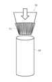
- the plurality of grooves 60 can be formed by using a mold 70 shown in FIG. 6, for example.
- the mold 70 has a plurality of protrusions 71 corresponding to the plurality of grooves 60 on the outer peripheral surface.
- a plurality of grooves 60 can be formed inside the opening of the cylindrical outer can 16 before crimping.
- the plurality of grooves 60 may be formed by any method, for example, by etching, cutting, or the like.
- the plurality of grooves 60 are formed in the outer can 16 before caulking along the axial direction so as to include positions corresponding to the shoulder portions 38 .
- the circumference of the shoulder 38 formed by bending the open side of the outer can 16 inward toward the peripheral edge 48 of the sealing body 17 during caulking becomes shorter toward the tip of the shoulder 38. Therefore, when the outer can 16 is caulked, the shoulder portion 38 receives a compressive load in the circumferential direction, and this compressive load increases toward the distal end side of the shoulder portion 38.
- a groove 60 extending in the axial direction is provided on the opening side of the outer can 16 before caulking. Therefore, during caulking, part of the flesh of the shoulder portion 38 that receives a compressive load can escape into the groove 60. Therefore, the compressive load in the circumferential direction that the shoulder portion 38 receives during caulking can be alleviated, and the occurrence of scratches on the shoulder portion 38 can be suppressed.
- the groove 60 extends to the inner end 38a of the shoulder portion 38, a portion of the meat can be reliably released into the groove 60 at the radial location where the circumference is the shortest due to caulking. Therefore, the compressive load in the circumferential direction that the shoulder portion 38 receives can be effectively alleviated, so that the occurrence of scratches on the shoulder portion 38 can be effectively suppressed. Furthermore, since the width of the groove 60 increases toward the inner end 38a of the shoulder 38, the compressive load in the circumferential direction that the shoulder 38 receives can be more effectively alleviated, thereby preventing damage to the shoulder 38. can be effectively suppressed.
- the technique of the present disclosure can secure the mechanical strength of the shoulder 38 of the outer can 16, so that the cylindrical battery 10 can be better sealed. Sexuality can also be realized.
- the groove 60 has a depth of 10% or more of the thickness of the outer can 16, part of the meat can reliably escape into the groove 60 during caulking, so that the occurrence of scratches can be effectively suppressed.
- the groove 60 has a depth of 30% or less of the thickness of the outer can 16, the rigidity of the shoulder portion 38 can be made sufficiently large, so that excellent sealing performance can be achieved. If the average width of the grooves 60 is 0.03% or more of the circumference of the outer can 16, part of the meat can reliably escape into the grooves 60 during caulking, thereby effectively preventing the occurrence of scratches. It can be suppressed.
- the average groove width of the grooves 60 is 0.06% or less of the circumference of the open end 38a of the outer can 16, the rigidity of the shoulder portion 38 can be made sufficiently large, thereby achieving excellent sealing performance. can.
- the present disclosure is not limited to the above-described embodiments and modifications thereof, and various improvements and changes can be made within the scope of the claims of the present application and their equivalents.
- a case has been described in which a portion of the groove 60 is located on the inner circumferential surface of the outer can 16, but the groove may be formed only on the inner surface of the shoulder portion 38.
- the groove 60 has been described as extending to the inner end 38a of the shoulder 38, the groove does not have to extend to the inner end of the shoulder.
- the width of the groove 60 may be substantially constant.
- the depth of the groove 60 may not be constant, and may become deeper toward the inner end of the shoulder portion, for example. Further, the groove may extend in a direction slightly inclined with respect to the radial direction.
Abstract
A cylindrical battery (10) includes: an electrode body (14) in which a positive electrode (11) and a negative electrode (12) are wound with a separator (13) therebetween; a bottomed cylindrical external can (16) that accommodates the electrode body (14); and a sealing body (17) that is fixed by staking at an opening of the external can (16) via a gasket (28). The external can (16) includes an annular shoulder portion (38) that presses the gasket (28) in the axial direction. A plurality of grooves (60) that are positioned at intervals in the circumferential direction and extend in substantially radial directions are provided on the inner surface of the shoulder portion (38).
Description
本開示は、円筒形電池に関する。
The present disclosure relates to cylindrical batteries.
従来、円筒形電池としては、特許文献1に記載されているものがある。この円筒形電池は、外装缶と封口体との間に配置されるガスケットを備える。封口体は、ガスケットを介して外装缶の開口部にかしめ固定される。外装缶は、肩部、溝入れ部、筒状部、及び底部を有する。肩部は、封口体を外装缶にかしめ固定する際に、外装缶の上端部を封口体の周縁部に向かって内側に折り曲げて形成される。この円筒形電池では、かしめ時の外装缶の波打ちを抑制するため、外装缶の肩部に内側端に繋がる複数の切欠きが設けられている。
Conventionally, as a cylindrical battery, there is one described in Patent Document 1. This cylindrical battery includes a gasket placed between the outer can and the sealing body. The sealing body is caulked and fixed to the opening of the outer can via a gasket. The outer can has a shoulder, a groove, a cylindrical portion, and a bottom. The shoulder portion is formed by bending the upper end of the outer can inward toward the peripheral edge of the closure when caulking and fixing the closure to the outer can. In this cylindrical battery, in order to suppress the waving of the outer can during caulking, the shoulder of the outer can is provided with a plurality of notches connected to the inner end.
本願発明者は、外装缶の硬度が高い場合にかしめ時に外装缶の肩部に傷が生じる場合があることを確認した。そこで、本開示の目的は、外装缶の肩部に傷が生じにくく、封止性も優れる円筒形電池を提供することにある。
The inventor of the present application has confirmed that when the hardness of the outer can is high, scratches may occur on the shoulder portion of the outer can during caulking. Therefore, an object of the present disclosure is to provide a cylindrical battery that is less prone to damage on the shoulder of the outer can and has excellent sealing performance.
上記課題を解決するため、本開示に係る円筒形電池は、正極と負極がセパレータを介して巻回された電極体と、電極体を収容する有底筒状の外装缶と、外装缶の開口部にガスケットを介してかしめ固定される封口体と、を備え、外装缶は、ガスケットを軸方向に押圧する環状の肩部を有し、肩部の内面に、周方向に間隔をおいて位置すると共に略径方向に延在する複数の溝が設けられている。
In order to solve the above problems, a cylindrical battery according to the present disclosure includes an electrode body in which a positive electrode and a negative electrode are wound with a separator in between, a bottomed cylindrical outer can housing the electrode body, and an opening of the outer can. The outer can has an annular shoulder that presses the gasket in the axial direction, and the outer can has an annular shoulder that presses the gasket in the axial direction. At the same time, a plurality of grooves extending in a substantially radial direction are provided.
前記溝は、僅かに径方向に対して傾斜する方向に延在してもよく、例えば、径方向に対して2°以下の角度で傾斜する方向に延在してもよい。
The groove may extend in a direction slightly inclined to the radial direction, for example, may extend in a direction inclined at an angle of 2° or less to the radial direction.
本開示に係る円筒形電池によれば、外装缶の肩部に傷が生じにくく、良好な封止性も実現できる。
According to the cylindrical battery according to the present disclosure, the shoulder portion of the outer can is less likely to be damaged, and good sealing performance can also be achieved.
以下、図面を参照しながら、本開示に係る円筒形電池の実施形態について詳細に説明する。なお、本開示の円筒形電池は、一次電池でもよく、二次電池でもよい。また、水系電解質を用いた電池でもよく、非水系電解質を用いた電池でもよい。以下では、一実施形態である円筒形電池10として、非水電解質を用いた非水電解質二次電池(リチウムイオン電池)を例示するが、本開示の円筒形電池はこれに限定されない。
Hereinafter, embodiments of the cylindrical battery according to the present disclosure will be described in detail with reference to the drawings. Note that the cylindrical battery of the present disclosure may be a primary battery or a secondary battery. Further, a battery using an aqueous electrolyte or a non-aqueous electrolyte may be used. In the following, a non-aqueous electrolyte secondary battery (lithium ion battery) using a non-aqueous electrolyte will be exemplified as the cylindrical battery 10 that is one embodiment, but the cylindrical battery of the present disclosure is not limited to this.
以下で説明する実施形態や変形例の特徴部分を適宜に組み合わせて新たな実施形態を構築することは当初から想定されている。以下の実施形態では、図面において同一構成に同一符号を付し、重複する説明を省略する。また、複数の図面には、模式図が含まれ、異なる図間において、各部材における、縦、横、高さ等の寸法比は、必ずしも一致しない。本明細書では、円筒形電池10の軸方向(高さ方向)の封口体17側を「上」とし、軸方向の外装缶16の底部55側を「下」とする。また、以下で説明される構成要素のうち、最上位概念を示す独立請求項に記載されていない構成要素については、任意の構成要素であり、必須の構成要素ではない。
It has been envisioned from the beginning that a new embodiment will be constructed by appropriately combining the characteristic parts of the embodiments and modifications described below. In the following embodiments, the same components are denoted by the same reference numerals in the drawings, and overlapping explanations will be omitted. Furthermore, the plurality of drawings include schematic diagrams, and the dimensional ratios of each member, such as length, width, and height, do not necessarily match between different drawings. In this specification, the axial direction (height direction) side of the sealing body 17 of the cylindrical battery 10 is referred to as the "upper", and the axial direction of the bottom 55 of the outer can 16 is referred to as the "lower". Furthermore, among the constituent elements described below, constituent elements that are not described in the independent claim indicating the most significant concept are optional constituent elements and are not essential constituent elements.
図1は、本開示の一実施形態に係る円筒形電池10の軸方向の断面図であり、図2は、円筒形電池10の電極体14の斜視図である。図1に示すように、円筒形電池10は、巻回型の電極体14、非水電解質(図示せず)、電極体14及び非水電解質を収容する有底筒状で金属製の外装缶16、及び外装缶16の開口部を塞ぐ封口体17を備える。図2に示すように、電極体14は、長尺状の正極11と長尺状の負極12が長尺状の2枚のセパレータ13を介して巻回された巻回構造を有する。
FIG. 1 is an axial cross-sectional view of a cylindrical battery 10 according to an embodiment of the present disclosure, and FIG. 2 is a perspective view of an electrode body 14 of the cylindrical battery 10. As shown in FIG. 1, the cylindrical battery 10 includes a wound electrode body 14, a nonaqueous electrolyte (not shown), and a bottomed cylindrical metal outer can that houses the electrode body 14 and the nonaqueous electrolyte. 16, and a sealing body 17 that closes the opening of the outer can 16. As shown in FIG. 2, the electrode body 14 has a wound structure in which an elongated positive electrode 11 and an elongated negative electrode 12 are wound with two elongated separators 13 in between.
負極12は、リチウムの析出を防止するために、正極11よりも一回り大きな寸法で形成される。即ち、負極12は、正極11より長手方向及び幅方向(短手方向)に長く形成される。また、2枚のセパレータ13は、少なくとも正極11よりも一回り大きな寸法で形成され、例えば正極11を挟むように配置される。図1に示すように、負極12は、電極体14の巻き始め端を構成してもよい。又は、セパレータ13が負極12の巻き始め側端を超えて延出して電極体14の巻き始め端を構成してもよい。
The negative electrode 12 is formed to be one size larger than the positive electrode 11 in order to prevent precipitation of lithium. That is, the negative electrode 12 is formed longer than the positive electrode 11 in the longitudinal direction and the width direction (short direction). Further, the two separators 13 are formed to be at least one size larger than the positive electrode 11, and are arranged to sandwich the positive electrode 11, for example. As shown in FIG. 1, the negative electrode 12 may constitute the winding start end of the electrode body 14. Alternatively, the separator 13 may extend beyond the winding start end of the negative electrode 12 to constitute the winding start end of the electrode body 14.
非水電解質は、非水溶媒と、非水溶媒に溶解した電解質塩とを含む。非水溶媒には、例えばエステル類、エーテル類、ニトリル類、アミド類、およびこれらの2種以上の混合溶媒等を用いてもよい。非水溶媒は、これら溶媒の水素原子の少なくとも一部をフッ素等のハロゲン原子で置換したハロゲン置換体を含有してもよい。なお、非水電解質は液体電解質に限定されず、ゲル状ポリマー等を用いた固体電解質であってもよい。電解質塩には、LiPF6等のリチウム塩が使用される。
The non-aqueous electrolyte includes a non-aqueous solvent and an electrolyte salt dissolved in the non-aqueous solvent. As the non-aqueous solvent, for example, esters, ethers, nitriles, amides, and mixed solvents of two or more of these may be used. The non-aqueous solvent may contain a halogen-substituted product in which at least a portion of the hydrogen atoms of these solvents are replaced with halogen atoms such as fluorine. Note that the non-aqueous electrolyte is not limited to a liquid electrolyte, and may be a solid electrolyte using a gel-like polymer or the like. A lithium salt such as LiPF 6 is used as the electrolyte salt.
正極11は、正極芯体と、正極芯体の両面に形成された正極合剤層とを有する。正極芯体には、アルミニウム、アルミニウム合金など、正極11の電位範囲で安定な金属箔、当該金属を表層に配置したフィルム等を用いることができる。正極合剤層は、正極活物質、導電剤、及び結着剤を含む。正極11は、例えば正極芯体上に正極活物質、導電剤、及び結着剤等を含む正極合剤スラリーを塗布し、塗膜を乾燥させた後、圧縮して正極合剤層を正極芯体の両面に形成することにより作製できる。
The positive electrode 11 has a positive electrode core and positive electrode mixture layers formed on both sides of the positive electrode core. For the positive electrode core, a metal foil such as aluminum or an aluminum alloy that is stable in the potential range of the positive electrode 11, a film in which the metal is disposed on the surface, or the like can be used. The positive electrode mixture layer includes a positive electrode active material, a conductive agent, and a binder. The positive electrode 11 is made by, for example, applying a positive electrode mixture slurry containing a positive electrode active material, a conductive agent, a binder, etc. onto a positive electrode core, drying the coating film, and then compressing the positive electrode mixture layer to form a positive electrode core. It can be made by forming it on both sides of the body.
正極活物質は、リチウム含有金属複合酸化物を主成分として構成される。リチウム含有金属複合酸化物に含有される金属元素としては、Ni、Co、Mn、Al、B、Mg、Ti、V、Cr、Fe、Cu、Zn、Ga、Sr、Zr、Nb、In、Sn、Ta、W等が挙げられる。好ましいリチウム含有金属複合酸化物の一例は、Ni、Co、Mn、Alの少なくとも1種を含有する複合酸化物である。
The positive electrode active material is composed of a lithium-containing metal composite oxide as a main component. Metal elements contained in the lithium-containing metal composite oxide include Ni, Co, Mn, Al, B, Mg, Ti, V, Cr, Fe, Cu, Zn, Ga, Sr, Zr, Nb, In, and Sn. , Ta, W, etc. An example of a preferable lithium-containing metal composite oxide is a composite oxide containing at least one of Ni, Co, Mn, and Al.
正極合剤層に含まれる導電剤としては、カーボンブラック、アセチレンブラック、ケッチェンブラック、黒鉛等の炭素材料が例示できる。正極合剤層に含まれる結着剤としては、ポリテトラフルオロエチレン(PTFE)、ポリフッ化ビニリデン(PVdF)等のフッ素樹脂、ポリアクリロニトリル(PAN)、ポリイミド樹脂、アクリル樹脂、ポリオレフィン樹脂などが例示できる。これらの樹脂と、カルボキシメチルセルロース(CMC)又はその塩等のセルロース誘導体、ポリエチレンオキシド(PEO)などが併用されてもよい。
Examples of the conductive agent contained in the positive electrode mixture layer include carbon materials such as carbon black, acetylene black, Ketjen black, and graphite. Examples of the binder included in the positive electrode mixture layer include fluororesins such as polytetrafluoroethylene (PTFE) and polyvinylidene fluoride (PVdF), polyacrylonitrile (PAN), polyimide resins, acrylic resins, and polyolefin resins. . These resins may be used in combination with cellulose derivatives such as carboxymethyl cellulose (CMC) or its salts, polyethylene oxide (PEO), and the like.
負極12は、負極芯体と、負極芯体の両面に形成された負極合剤層とを有する。負極芯体には、銅、銅合金など、負極12の電位範囲で安定な金属箔、当該金属を表層に配置したフィルム等を用いることができる。負極合剤層は、負極活物質、及び結着剤を含む。負極12は、例えば負極芯体上に負極活物質、及び結着剤等を含む負極合剤スラリーを塗布し、塗膜を乾燥させた後、圧縮して負極合剤層を負極芯体の両面に形成することにより作製できる。
The negative electrode 12 has a negative electrode core and negative electrode mixture layers formed on both sides of the negative electrode core. For the negative electrode core, a metal foil such as copper or a copper alloy that is stable in the potential range of the negative electrode 12, a film with the metal disposed on the surface, or the like can be used. The negative electrode mixture layer includes a negative electrode active material and a binder. The negative electrode 12 is produced by, for example, applying a negative electrode mixture slurry containing a negative electrode active material, a binder, etc. onto a negative electrode core, drying the coating film, and then compressing the negative electrode mixture layer onto both sides of the negative electrode core. It can be manufactured by forming
負極活物質には、一般的に、リチウムイオンを可逆的に吸蔵、放出する炭素材料が用いられる。好ましい炭素材料は、鱗片状黒鉛、塊状黒鉛、土状黒鉛等の天然黒鉛、塊状人造黒鉛、黒鉛化メソフェーズカーボンマイクロビーズ等の人造黒鉛などの黒鉛である。負極合剤層には、負極活物質として、ケイ素(Si)を含有するSi材料が含まれていてもよい。また、負極活物質には、Si以外のリチウムと合金化する金属、当該金属を含有する合金、当該金属を含有する化合物等が用いられてもよい。
A carbon material that reversibly occludes and releases lithium ions is generally used as the negative electrode active material. Preferred carbon materials include natural graphite such as flaky graphite, lumpy graphite, and earthy graphite, and graphite such as artificial graphite such as lumpy artificial graphite and graphitized mesophase carbon microbeads. The negative electrode mixture layer may contain a Si material containing silicon (Si) as a negative electrode active material. Furthermore, a metal other than Si that is alloyed with lithium, an alloy containing the metal, a compound containing the metal, etc. may be used as the negative electrode active material.
負極合剤層に含まれる結着剤には、正極11の場合と同様に、フッ素樹脂、PAN、ポリイミド樹脂、アクリル樹脂、ポリオレフィン樹脂等を用いてもよいが、好ましくはスチレン-ブタジエンゴム(SBR)又はその変性体を用いる。負極合剤層には、例えばSBR等に加えて、CMC又はその塩、ポリアクリル酸(PAA)又はその塩、ポリビニルアルコールなどが含まれていてもよい。
As in the case of the positive electrode 11, the binder contained in the negative electrode mixture layer may be a fluororesin, PAN, polyimide resin, acrylic resin, polyolefin resin, etc., but preferably styrene-butadiene rubber (SBR). ) or its modified form. The negative electrode mixture layer may contain, for example, in addition to SBR or the like, CMC or a salt thereof, polyacrylic acid (PAA) or a salt thereof, polyvinyl alcohol, or the like.
セパレータ13には、イオン透過性及び絶縁性を有する多孔性シートが用いられる。多孔性シートの具体例としては、微多孔薄膜、織布、不織布等が挙げられる。セパレータ13の材質としては、ポリエチレン、ポリプロピレン等のポリオレフィン樹脂、セルロースなどが好ましい。セパレータ13は、単層構造、積層構造のいずれでもよい。セパレータ13の表面には、耐熱層などが形成されてもよい。
A porous sheet having ion permeability and insulation properties is used for the separator 13. Specific examples of porous sheets include microporous thin films, woven fabrics, and nonwoven fabrics. Preferable materials for the separator 13 include polyolefin resins such as polyethylene and polypropylene, cellulose, and the like. The separator 13 may have either a single layer structure or a laminated structure. A heat-resistant layer or the like may be formed on the surface of the separator 13.
図1に示すように、正極11には、正極リード20が接合され、負極12の長手方向の巻き始め側には、負極リード21が接合される。円筒形電池10は、電極体14の上方に絶縁板18を有し、電極体14の下方に絶縁板19を有する。正極リード20は、絶縁板18の貫通孔を通って封口体17側に延び、負極リード21は、絶縁板19の貫通孔を通って外装缶16の底部55側に延びる。正極リード20は、封口体17の底板23の下面に溶接等で接続される。封口体17の天板を構成する端子キャップ27が底板23と電気的に接続され、端子キャップ27が正極端子となる。また、負極リード21は、金属製の外装缶16の底部55の内面に溶接等で接続され、外装缶16が負極端子となる。
As shown in FIG. 1, a positive electrode lead 20 is connected to the positive electrode 11, and a negative electrode lead 21 is connected to the winding start side of the negative electrode 12 in the longitudinal direction. The cylindrical battery 10 has an insulating plate 18 above the electrode body 14 and an insulating plate 19 below the electrode body 14. The positive electrode lead 20 extends through the through hole of the insulating plate 18 to the sealing body 17 side, and the negative electrode lead 21 extends through the through hole of the insulating plate 19 to the bottom 55 side of the outer can 16. The positive electrode lead 20 is connected to the lower surface of the bottom plate 23 of the sealing body 17 by welding or the like. A terminal cap 27 constituting the top plate of the sealing body 17 is electrically connected to the bottom plate 23, and the terminal cap 27 becomes a positive terminal. Further, the negative electrode lead 21 is connected to the inner surface of the bottom portion 55 of the metal outer can 16 by welding or the like, and the outer can 16 serves as a negative electrode terminal.
図1及び図2に示す例では、正極リード20は、正極芯体における巻回方向の中央部等の中間部に電気的に接続され、負極リード21は、負極芯体における巻回方向の巻き始め側端部に電気的に接続される。さらに、電極体14の最外周面には負極芯体が露出して外装缶16の内面に接触している。しかし、負極リードは、負極芯体における巻回方向の巻き終わり側端部に電気的に接続されてもよい。又は、電極体が2つの負極リードを有して、一方の負極リードが、負極芯体における巻回方向の巻き始め側端部に電気的に接続され、他方の負極リードが、負極芯体における巻回方向の巻き終わり側端部に電気的に接続されてもよい。図1に示すように負極芯体が外装缶の内面に接触している場合、負極リード21を省略してもよい。
In the example shown in FIGS. 1 and 2, the positive electrode lead 20 is electrically connected to an intermediate portion of the positive electrode core in the winding direction, and the negative electrode lead 21 is connected to the winding direction of the negative electrode core. It is electrically connected to the starting end. Furthermore, a negative electrode core is exposed on the outermost peripheral surface of the electrode body 14 and is in contact with the inner surface of the outer can 16 . However, the negative electrode lead may be electrically connected to the end of the negative electrode core in the winding direction. Alternatively, the electrode body has two negative electrode leads, one negative electrode lead is electrically connected to the winding start side end in the winding direction of the negative electrode core, and the other negative electrode lead is connected to the winding start side end of the negative electrode core in the winding direction. It may be electrically connected to the winding end side end in the winding direction. When the negative electrode core is in contact with the inner surface of the outer can as shown in FIG. 1, the negative electrode lead 21 may be omitted.
円筒形電池10は、外装缶16と封口体17との間に配置される樹脂製のガスケット28を更に備える。封口体17は、ガスケット28を介して外装缶16の開口部にかしめ固定される。これにより、円筒形電池10の内部空間が密閉される。ガスケット28は、外装缶16と封口体17に挟持され、封口体17を外装缶16に対して絶縁する。ガスケット28は、電池内部の気密性を保つためのシール材の役割と、外装缶16と封口体17を絶縁する絶縁材としての役割を有する。
The cylindrical battery 10 further includes a resin gasket 28 disposed between the outer can 16 and the sealing body 17. The sealing body 17 is caulked and fixed to the opening of the exterior can 16 via a gasket 28 . Thereby, the internal space of the cylindrical battery 10 is sealed. The gasket 28 is sandwiched between the outer can 16 and the sealing body 17 and insulates the sealing body 17 from the outer can 16. The gasket 28 has the role of a sealing material for maintaining airtightness inside the battery and the role of an insulating material for insulating the outer can 16 and the sealing body 17.
外装缶16は、電極体14と非水電解質を収容し、肩部38、溝入れ部34、筒状部30、及び底部55を有する。溝入れ部34は、例えば、外装缶16の側面の一部を、径方向内側にスピニング加工して径方向内方側に環状に窪ませることで形成できる。肩部38は、封口体17を外装缶16にかしめ固定する際に、外装缶16の上端部を封口体17の周縁部48に向かって内側に折り曲げて形成される。
The outer can 16 accommodates the electrode body 14 and the nonaqueous electrolyte, and has a shoulder portion 38, a grooved portion 34, a cylindrical portion 30, and a bottom portion 55. The grooved portion 34 can be formed, for example, by spinning a part of the side surface of the outer can 16 radially inward to create an annular depression radially inward. The shoulder portion 38 is formed by bending the upper end of the outer can 16 inward toward the peripheral edge 48 of the closure 17 when the closure 17 is fixed to the outer can 16 by caulking.
封口体17は、電極体14側から順に、底板23、下弁体24、絶縁部材25、上弁体26、及び端子キャップ27が積層された構造を有する。封口体17を構成する各部材は、例えば円板形状又はリング形状を有し、絶縁部材25を除く各部材は互いに電気的に接続されている。底板23は、少なくとも1つの貫通孔23aを有する。また、下弁体24と上弁体26は、各々の中央部で接続され、各々の周縁部の間には絶縁部材25が介在している。
The sealing body 17 has a structure in which a bottom plate 23, a lower valve body 24, an insulating member 25, an upper valve body 26, and a terminal cap 27 are laminated in order from the electrode body 14 side. Each member constituting the sealing body 17 has, for example, a disk shape or a ring shape, and each member except the insulating member 25 is electrically connected to each other. The bottom plate 23 has at least one through hole 23a. Further, the lower valve body 24 and the upper valve body 26 are connected at their respective central portions, and an insulating member 25 is interposed between their respective peripheral portions.
円筒形電池10が異常発熱して、円筒形電池10の内圧が上昇すると、下弁体24が上弁体26を端子キャップ27側に押し上げるように変形して破断し、下弁体24と上弁体26の間の電流経路が遮断される。さらに内圧が上昇すると、上弁体26が破断して、端子キャップ27の貫通孔27aからガスが排出される。このガスの排出により、円筒形電池10の内圧が過度に上昇して円筒形電池10が破裂することを防止でき、円筒形電池10の安全性を高くできる。
When the cylindrical battery 10 generates abnormal heat and the internal pressure of the cylindrical battery 10 increases, the lower valve body 24 deforms and breaks so as to push the upper valve body 26 toward the terminal cap 27, causing the lower valve body 24 and the upper valve body 26 to The current path between the valve bodies 26 is cut off. When the internal pressure further increases, the upper valve body 26 breaks and gas is discharged from the through hole 27a of the terminal cap 27. By discharging this gas, it is possible to prevent the internal pressure of the cylindrical battery 10 from rising excessively and causing the cylindrical battery 10 to burst, thereby increasing the safety of the cylindrical battery 10.
図3は、図1における外装缶16の肩部38周辺の拡大断面図である。図3に示すように、外装缶16の開口部(外装缶16の開口側端部)の内面には複数の溝60が設けられる。複数の溝60は、周方向に間隔をおいて設けられ、図3に示す例では、周方向に略等間隔に設けられる。溝60は、肩部38の内面に設けられると共に肩部38の径方向の内側端38aまで延びている。肩部38の径方向の内側端38aは、外装缶16の開口端に対応する。溝60の一部は、外装缶16の内周面62に位置してもよい。溝60は、内側端38a側に行くにしたがって溝幅が大きくなっている。溝60は、略一定の深さを有する。溝60の深さは、例えば、外装缶16の厚さの10%以上30%以下の深さになっている。また、溝60の溝幅の平均は、かしめ前の外装缶の周長の0.03%以上0.06%以下の長さになっている。
FIG. 3 is an enlarged sectional view of the vicinity of the shoulder portion 38 of the outer can 16 in FIG. 1. As shown in FIG. 3, a plurality of grooves 60 are provided on the inner surface of the opening of the outer can 16 (the end on the opening side of the outer can 16). The plurality of grooves 60 are provided at intervals in the circumferential direction, and in the example shown in FIG. 3, they are provided at approximately equal intervals in the circumferential direction. The groove 60 is provided on the inner surface of the shoulder 38 and extends to the radially inner end 38a of the shoulder 38. A radially inner end 38 a of the shoulder portion 38 corresponds to the open end of the outer can 16 . A portion of the groove 60 may be located on the inner circumferential surface 62 of the outer can 16. The width of the groove 60 increases toward the inner end 38a. Groove 60 has a substantially constant depth. The depth of the groove 60 is, for example, 10% or more and 30% or less of the thickness of the outer can 16. Further, the average width of the grooves 60 is 0.03% or more and 0.06% or less of the circumferential length of the outer can before caulking.
図4は、かしめ前の外装缶16の開口側を示す斜視図であり、図5は、図4に示す領域Rの拡大斜視図である。図4に示すように、外装缶16は、略円筒形の形状を有する。外装缶16は、軸方向(高さ方向)に延在する複数の溝60を内面に有する。複数の溝60は、周方向に略等間隔に設けられる。溝60は、開口端まで軸方向に延在する。図5に示すように、溝60の溝幅は、開口端側に行くにしたがって大きくなっている。
FIG. 4 is a perspective view showing the opening side of the exterior can 16 before caulking, and FIG. 5 is an enlarged perspective view of region R shown in FIG. 4. As shown in FIG. 4, the outer can 16 has a substantially cylindrical shape. The outer can 16 has a plurality of grooves 60 extending in the axial direction (height direction) on its inner surface. The plurality of grooves 60 are provided at approximately equal intervals in the circumferential direction. Groove 60 extends axially to the open end. As shown in FIG. 5, the width of the groove 60 increases toward the open end.
複数の溝60は、例えば、図6に示す金型70を用いることで形成できる。詳しくは、金型70は、複数の溝60に対応する複数の突出部71を外周面に有する。この金型70をかしめ前の円筒形状の外装缶16の開口部内側に圧入して軸方向に出し入れすることで、複数の溝60をかしめ前の外装缶16の開口部内側に形成できる。なお、複数の溝60は、如何なる方法で形成されてもよく、例えば、エッチングや切削等で形成されてもよい。複数の溝60は、かしめ前の外装缶16に軸方向に沿って肩部38に相当する位置を含むように形成される。
The plurality of grooves 60 can be formed by using a mold 70 shown in FIG. 6, for example. Specifically, the mold 70 has a plurality of protrusions 71 corresponding to the plurality of grooves 60 on the outer peripheral surface. By press-fitting this mold 70 inside the opening of the cylindrical outer can 16 before crimping and moving it in and out in the axial direction, a plurality of grooves 60 can be formed inside the opening of the cylindrical outer can 16 before crimping. Note that the plurality of grooves 60 may be formed by any method, for example, by etching, cutting, or the like. The plurality of grooves 60 are formed in the outer can 16 before caulking along the axial direction so as to include positions corresponding to the shoulder portions 38 .
次に、かしめ前の外装缶16の開口部内側に複数の溝を設けることの作用効果について説明する。かしめ時に外装缶16の開口側を封口体17の周縁部48に向かって内側に折り曲げて形成された肩部38周長は、肩部38の先端に行くにしたがって短くなる。したがって、外装缶16のかしめ時に、肩部38が周方向の圧縮荷重を受け、この圧縮荷重は、肩部38の先端側に行く程大きくなる。
Next, the effects of providing a plurality of grooves inside the opening of the outer can 16 before caulking will be explained. The circumference of the shoulder 38 formed by bending the open side of the outer can 16 inward toward the peripheral edge 48 of the sealing body 17 during caulking becomes shorter toward the tip of the shoulder 38. Therefore, when the outer can 16 is caulked, the shoulder portion 38 receives a compressive load in the circumferential direction, and this compressive load increases toward the distal end side of the shoulder portion 38.
しかしながら、本開示の技術によれば、かしめ前の外装缶16の開口側に軸方向に延在する溝60が設けられている。そのため、かしめ時に、圧縮荷重を受ける肩部38の肉の一部を溝60に逃がすことができる。したがって、かしめ時に肩部38が受ける周方向の圧縮荷重を緩和でき、肩部38の傷の発生を抑制できる。
However, according to the technology of the present disclosure, a groove 60 extending in the axial direction is provided on the opening side of the outer can 16 before caulking. Therefore, during caulking, part of the flesh of the shoulder portion 38 that receives a compressive load can escape into the groove 60. Therefore, the compressive load in the circumferential direction that the shoulder portion 38 receives during caulking can be alleviated, and the occurrence of scratches on the shoulder portion 38 can be suppressed.
また、溝60が、肩部38の内側端38aまで延びているので、かしめによって周長が最も短くなる径方向箇所で肉の一部を確実に溝60に逃がすことができる。したって、肩部38が受ける周方向の圧縮荷重を効果的に緩和できるため、肩部38の傷の発生を効果的に抑制できる。さらに、溝60の幅が、肩部38の内側端38aに行くにしたがって大きくなっているので、肩部38が受ける周方向の圧縮荷重をより効果的に緩和でき、肩部38の傷の発生を効果的に抑制できる。
Additionally, since the groove 60 extends to the inner end 38a of the shoulder portion 38, a portion of the meat can be reliably released into the groove 60 at the radial location where the circumference is the shortest due to caulking. Therefore, the compressive load in the circumferential direction that the shoulder portion 38 receives can be effectively alleviated, so that the occurrence of scratches on the shoulder portion 38 can be effectively suppressed. Furthermore, since the width of the groove 60 increases toward the inner end 38a of the shoulder 38, the compressive load in the circumferential direction that the shoulder 38 receives can be more effectively alleviated, thereby preventing damage to the shoulder 38. can be effectively suppressed.
外装缶の肩部にスリット状の切り欠きを設ける場合に比べて本開示の技術によれば、外装缶16の肩部38の機械的強度を確保できるため、円筒形電池10の良好な封止性も実現できる。
Compared to the case where a slit-shaped notch is provided in the shoulder of the outer can, the technique of the present disclosure can secure the mechanical strength of the shoulder 38 of the outer can 16, so that the cylindrical battery 10 can be better sealed. Sexuality can also be realized.
溝60が、外装缶16の厚さの10%以上の深さを有すると、かしめ時に肉の一部を溝60に確実に逃がすことができるため、傷の発生を効果的に抑制できる。溝60が、外装缶16の厚さの30%以下の深さを有すると、肩部38の剛性を十分な大きさにできるため、優れた封止性を実現できる。溝60の溝幅の平均が、外装缶16の周長の0.03%以上であると、かしめ時に肉の一部を溝60に確実に逃がすことができるため、傷の発生を効果的に抑制できる。溝60の溝幅の平均が、外装缶16の開口端38aの周長の0.06%以下であると、肩部38の剛性を十分な大きさにできるため、優れた封止性を実現できる。
When the groove 60 has a depth of 10% or more of the thickness of the outer can 16, part of the meat can reliably escape into the groove 60 during caulking, so that the occurrence of scratches can be effectively suppressed. When the groove 60 has a depth of 30% or less of the thickness of the outer can 16, the rigidity of the shoulder portion 38 can be made sufficiently large, so that excellent sealing performance can be achieved. If the average width of the grooves 60 is 0.03% or more of the circumference of the outer can 16, part of the meat can reliably escape into the grooves 60 during caulking, thereby effectively preventing the occurrence of scratches. It can be suppressed. When the average groove width of the grooves 60 is 0.06% or less of the circumference of the open end 38a of the outer can 16, the rigidity of the shoulder portion 38 can be made sufficiently large, thereby achieving excellent sealing performance. can.
なお、本開示は、上記実施形態およびその変形例に限定されるものではなく、本願の特許請求の範囲に記載された事項およびその均等な範囲において種々の改良や変更が可能である。例えば、上記実施形態では、溝60の一部が外装缶16の内周面に位置する場合について説明したが、溝は肩部38の内面にのみ形成してもよい。また、溝60が肩部38の内側端38aまで延びる場合について説明したが、溝は、肩部の内側端まで延びていなくてもよい。また、溝60の溝幅が先端に行くにしたがって大きくなる場合について説明したが、溝の幅は、略一定でもよい。また、溝60の深さが、略一定である場合について説明したが、溝60の深さは、一定でなくてもよく、例えば、肩部の内側端に行くにしたがって深くなってもよい。また、溝は、径方向に対して僅かに傾いた方向に延在してもよい。
Note that the present disclosure is not limited to the above-described embodiments and modifications thereof, and various improvements and changes can be made within the scope of the claims of the present application and their equivalents. For example, in the embodiment described above, a case has been described in which a portion of the groove 60 is located on the inner circumferential surface of the outer can 16, but the groove may be formed only on the inner surface of the shoulder portion 38. Furthermore, although the groove 60 has been described as extending to the inner end 38a of the shoulder 38, the groove does not have to extend to the inner end of the shoulder. Moreover, although the case has been described in which the width of the groove 60 increases toward the tip, the width of the groove may be substantially constant. Moreover, although the case where the depth of the groove 60 is substantially constant has been described, the depth of the groove 60 may not be constant, and may become deeper toward the inner end of the shoulder portion, for example. Further, the groove may extend in a direction slightly inclined with respect to the radial direction.
10 円筒形電池、 11 正極、 12 負極、 13 セパレータ、 14 電極体、 16 外装缶、 17 封口体、 18,19 絶縁板、 20 正極リード、 21 負極リード、 23 底板、 23a 貫通孔、 24 下弁体、 25 絶縁部材、 26 上弁体、 27 端子キャップ、 27a 貫通孔、 28 ガスケット、 30 筒状部、 34 溝入れ部、 38 肩部、 38a 内側端、 48 周縁部、 55 底部、 60 溝、 62 内周面、 70 金型、 71 金型の突出部。
10 Cylindrical battery, 11 Positive electrode, 12 Negative electrode, 13 Separator, 14 Electrode body, 16 External can, 17 Sealing body, 18,19 Insulating plate, 20 Positive electrode lead, 21 Negative electrode lead, 2 3 Bottom plate, 23a through hole, 24 lower valve Body, 25 Insulating member, 26 Upper valve body, 27 Terminal cap, 27a Through hole, 28 Gasket, 30 Cylindrical part, 34 Grooving part, 38 Shoulder part, 38a Inner end, 48 Peripheral part, 55 bottom, 60 groove, 62 Inner peripheral surface, 70 Mold, 71 Mold protrusion.
Claims (3)
- 正極と負極がセパレータを介して巻回された電極体と、
前記電極体を収容する有底筒状の外装缶と、
前記外装缶の開口部にガスケットを介してかしめ固定される封口体と、を備え、
前記外装缶は、前記ガスケットを軸方向に押圧する環状の肩部を有し、
前記肩部の内面に、周方向に間隔をおいて位置すると共に略径方向に延在する複数の溝が設けられている、円筒形電池。 an electrode body in which a positive electrode and a negative electrode are wound with a separator interposed therebetween;
a bottomed cylindrical outer can housing the electrode body;
a sealing body caulked and fixed to the opening of the outer can via a gasket,
The outer can has an annular shoulder that presses the gasket in the axial direction,
A cylindrical battery, wherein an inner surface of the shoulder portion is provided with a plurality of circumferentially spaced grooves and generally radially extending grooves. - 前記溝が、前記肩部の前記径方向の内側端まで延びている、請求項1に記載の円筒形電池。 The cylindrical battery of claim 1, wherein the groove extends to the radially inner end of the shoulder.
- 前記溝の幅が、前記径方向の内側に行くにしたがって大きくなっている、請求項1又は2に記載の円筒形電池。 The cylindrical battery according to claim 1 or 2, wherein the width of the groove increases toward the inside in the radial direction.
Applications Claiming Priority (2)
| Application Number | Priority Date | Filing Date | Title |
|---|---|---|---|
| JP2022-055049 | 2022-03-30 | ||
| JP2022055049 | 2022-03-30 |
Publications (1)
| Publication Number | Publication Date |
|---|---|
| WO2023189790A1 true WO2023189790A1 (en) | 2023-10-05 |
Family
ID=88201009
Family Applications (1)
| Application Number | Title | Priority Date | Filing Date |
|---|---|---|---|
| PCT/JP2023/010791 WO2023189790A1 (en) | 2022-03-30 | 2023-03-20 | Cylindrical battery |
Country Status (1)
| Country | Link |
|---|---|
| WO (1) | WO2023189790A1 (en) |
Citations (4)
| Publication number | Priority date | Publication date | Assignee | Title |
|---|---|---|---|---|
| JP2002231193A (en) * | 2001-01-26 | 2002-08-16 | Sony Corp | Sealed battery |
| JP2012234716A (en) * | 2011-05-02 | 2012-11-29 | Hitachi Vehicle Energy Ltd | Cylindrical secondary battery |
| WO2020137777A1 (en) * | 2018-12-28 | 2020-07-02 | パナソニックIpマネジメント株式会社 | Battery |
| WO2021193133A1 (en) * | 2020-03-25 | 2021-09-30 | 三洋電機株式会社 | Cylindrical battery |
-
2023
- 2023-03-20 WO PCT/JP2023/010791 patent/WO2023189790A1/en unknown
Patent Citations (4)
| Publication number | Priority date | Publication date | Assignee | Title |
|---|---|---|---|---|
| JP2002231193A (en) * | 2001-01-26 | 2002-08-16 | Sony Corp | Sealed battery |
| JP2012234716A (en) * | 2011-05-02 | 2012-11-29 | Hitachi Vehicle Energy Ltd | Cylindrical secondary battery |
| WO2020137777A1 (en) * | 2018-12-28 | 2020-07-02 | パナソニックIpマネジメント株式会社 | Battery |
| WO2021193133A1 (en) * | 2020-03-25 | 2021-09-30 | 三洋電機株式会社 | Cylindrical battery |
Similar Documents
| Publication | Publication Date | Title |
|---|---|---|
| WO2018061381A1 (en) | Non-aqueous electrolyte secondary battery | |
| JP7422680B2 (en) | Gasket and cylindrical battery | |
| US11183678B2 (en) | Electrode for nonaqueous electrolyte secondary battery and nonaqueous electrolyte secondary battery | |
| WO2022024712A1 (en) | Nonaqueous electrolyte secondary battery | |
| JP7461878B2 (en) | Non-aqueous electrolyte secondary battery | |
| WO2019244818A1 (en) | Nonaqueous electrolyte secondary battery | |
| WO2022202395A1 (en) | Cylindrical battery | |
| US20230387523A1 (en) | Cylindrical battery | |
| WO2023189790A1 (en) | Cylindrical battery | |
| JP2022152423A (en) | cylindrical battery | |
| JP7320166B2 (en) | secondary battery | |
| WO2024048145A1 (en) | Cylindrical battery | |
| CN113169399A (en) | Sealed battery | |
| WO2023210590A1 (en) | Cylindrical battery | |
| WO2023189792A1 (en) | Cylindrical cell | |
| WO2024048147A1 (en) | Cylindrical battery | |
| WO2023054005A1 (en) | Cylindrical battery | |
| WO2024070513A1 (en) | Cylindrical battery | |
| WO2023145674A1 (en) | Cylindrical nonaqueous electrolyte secondary battery | |
| WO2023085030A1 (en) | Cylindrical battery | |
| WO2023163139A1 (en) | Cylindrical nonaqueous electrolyte secondary battery | |
| WO2023145679A1 (en) | Nonaqueous electrolyte secondary battery | |
| US20240055719A1 (en) | Sealed battery | |
| WO2023162710A1 (en) | Cylindrical nonaqueous electrolyte secondary battery | |
| WO2023181853A1 (en) | Cylindrical battery |
Legal Events
| Date | Code | Title | Description |
|---|---|---|---|
| 121 | Ep: the epo has been informed by wipo that ep was designated in this application |
Ref document number: 23779806 Country of ref document: EP Kind code of ref document: A1 |