WO2023223783A1 - 反応装置 - Google Patents
反応装置 Download PDFInfo
- Publication number
- WO2023223783A1 WO2023223783A1 PCT/JP2023/016259 JP2023016259W WO2023223783A1 WO 2023223783 A1 WO2023223783 A1 WO 2023223783A1 JP 2023016259 W JP2023016259 W JP 2023016259W WO 2023223783 A1 WO2023223783 A1 WO 2023223783A1
- Authority
- WO
- WIPO (PCT)
- Prior art keywords
- reaction
- catalyst
- raw material
- material gas
- section
- Prior art date
- Legal status (The legal status is an assumption and is not a legal conclusion. Google has not performed a legal analysis and makes no representation as to the accuracy of the status listed.)
- Ceased
Links
Images


Classifications
-
- B—PERFORMING OPERATIONS; TRANSPORTING
- B01—PHYSICAL OR CHEMICAL PROCESSES OR APPARATUS IN GENERAL
- B01J—CHEMICAL OR PHYSICAL PROCESSES, e.g. CATALYSIS OR COLLOID CHEMISTRY; THEIR RELEVANT APPARATUS
- B01J8/00—Chemical or physical processes in general, conducted in the presence of fluids and solid particles; Apparatus for such processes
- B01J8/02—Chemical or physical processes in general, conducted in the presence of fluids and solid particles; Apparatus for such processes with stationary particles, e.g. in fixed beds
- B01J8/0278—Feeding reactive fluids
-
- C—CHEMISTRY; METALLURGY
- C07—ORGANIC CHEMISTRY
- C07C—ACYCLIC OR CARBOCYCLIC COMPOUNDS
- C07C1/00—Preparation of hydrocarbons from one or more compounds, none of them being a hydrocarbon
- C07C1/02—Preparation of hydrocarbons from one or more compounds, none of them being a hydrocarbon from oxides of a carbon
- C07C1/12—Preparation of hydrocarbons from one or more compounds, none of them being a hydrocarbon from oxides of a carbon from carbon dioxide with hydrogen
-
- B—PERFORMING OPERATIONS; TRANSPORTING
- B01—PHYSICAL OR CHEMICAL PROCESSES OR APPARATUS IN GENERAL
- B01J—CHEMICAL OR PHYSICAL PROCESSES, e.g. CATALYSIS OR COLLOID CHEMISTRY; THEIR RELEVANT APPARATUS
- B01J2208/00—Processes carried out in the presence of solid particles; Reactors therefor
- B01J2208/00008—Controlling the process
- B01J2208/00017—Controlling the temperature
- B01J2208/00026—Controlling or regulating the heat exchange system
- B01J2208/00035—Controlling or regulating the heat exchange system involving measured parameters
- B01J2208/00044—Temperature measurement
- B01J2208/00061—Temperature measurement of the reactants
-
- B—PERFORMING OPERATIONS; TRANSPORTING
- B01—PHYSICAL OR CHEMICAL PROCESSES OR APPARATUS IN GENERAL
- B01J—CHEMICAL OR PHYSICAL PROCESSES, e.g. CATALYSIS OR COLLOID CHEMISTRY; THEIR RELEVANT APPARATUS
- B01J2208/00—Processes carried out in the presence of solid particles; Reactors therefor
- B01J2208/00008—Controlling the process
- B01J2208/00017—Controlling the temperature
- B01J2208/00513—Controlling the temperature using inert heat absorbing solids in the bed
-
- B—PERFORMING OPERATIONS; TRANSPORTING
- B01—PHYSICAL OR CHEMICAL PROCESSES OR APPARATUS IN GENERAL
- B01J—CHEMICAL OR PHYSICAL PROCESSES, e.g. CATALYSIS OR COLLOID CHEMISTRY; THEIR RELEVANT APPARATUS
- B01J2208/00—Processes carried out in the presence of solid particles; Reactors therefor
- B01J2208/02—Processes carried out in the presence of solid particles; Reactors therefor with stationary particles
- B01J2208/023—Details
- B01J2208/024—Particulate material
- B01J2208/025—Two or more types of catalyst
-
- B—PERFORMING OPERATIONS; TRANSPORTING
- B01—PHYSICAL OR CHEMICAL PROCESSES OR APPARATUS IN GENERAL
- B01J—CHEMICAL OR PHYSICAL PROCESSES, e.g. CATALYSIS OR COLLOID CHEMISTRY; THEIR RELEVANT APPARATUS
- B01J8/00—Chemical or physical processes in general, conducted in the presence of fluids and solid particles; Apparatus for such processes
- B01J8/02—Chemical or physical processes in general, conducted in the presence of fluids and solid particles; Apparatus for such processes with stationary particles, e.g. in fixed beds
- B01J8/04—Chemical or physical processes in general, conducted in the presence of fluids and solid particles; Apparatus for such processes with stationary particles, e.g. in fixed beds the fluid passing successively through two or more beds
- B01J8/0403—Chemical or physical processes in general, conducted in the presence of fluids and solid particles; Apparatus for such processes with stationary particles, e.g. in fixed beds the fluid passing successively through two or more beds the fluid flow within the beds being predominantly horizontal
- B01J8/0423—Chemical or physical processes in general, conducted in the presence of fluids and solid particles; Apparatus for such processes with stationary particles, e.g. in fixed beds the fluid passing successively through two or more beds the fluid flow within the beds being predominantly horizontal through two or more otherwise shaped beds
- B01J8/0438—Chemical or physical processes in general, conducted in the presence of fluids and solid particles; Apparatus for such processes with stationary particles, e.g. in fixed beds the fluid passing successively through two or more beds the fluid flow within the beds being predominantly horizontal through two or more otherwise shaped beds the beds being placed next to each other
-
- B—PERFORMING OPERATIONS; TRANSPORTING
- B01—PHYSICAL OR CHEMICAL PROCESSES OR APPARATUS IN GENERAL
- B01J—CHEMICAL OR PHYSICAL PROCESSES, e.g. CATALYSIS OR COLLOID CHEMISTRY; THEIR RELEVANT APPARATUS
- B01J8/00—Chemical or physical processes in general, conducted in the presence of fluids and solid particles; Apparatus for such processes
- B01J8/02—Chemical or physical processes in general, conducted in the presence of fluids and solid particles; Apparatus for such processes with stationary particles, e.g. in fixed beds
- B01J8/04—Chemical or physical processes in general, conducted in the presence of fluids and solid particles; Apparatus for such processes with stationary particles, e.g. in fixed beds the fluid passing successively through two or more beds
- B01J8/0403—Chemical or physical processes in general, conducted in the presence of fluids and solid particles; Apparatus for such processes with stationary particles, e.g. in fixed beds the fluid passing successively through two or more beds the fluid flow within the beds being predominantly horizontal
- B01J8/0423—Chemical or physical processes in general, conducted in the presence of fluids and solid particles; Apparatus for such processes with stationary particles, e.g. in fixed beds the fluid passing successively through two or more beds the fluid flow within the beds being predominantly horizontal through two or more otherwise shaped beds
- B01J8/0442—Chemical or physical processes in general, conducted in the presence of fluids and solid particles; Apparatus for such processes with stationary particles, e.g. in fixed beds the fluid passing successively through two or more beds the fluid flow within the beds being predominantly horizontal through two or more otherwise shaped beds the beds being placed in separate reactors
-
- B—PERFORMING OPERATIONS; TRANSPORTING
- B01—PHYSICAL OR CHEMICAL PROCESSES OR APPARATUS IN GENERAL
- B01J—CHEMICAL OR PHYSICAL PROCESSES, e.g. CATALYSIS OR COLLOID CHEMISTRY; THEIR RELEVANT APPARATUS
- B01J8/00—Chemical or physical processes in general, conducted in the presence of fluids and solid particles; Apparatus for such processes
- B01J8/02—Chemical or physical processes in general, conducted in the presence of fluids and solid particles; Apparatus for such processes with stationary particles, e.g. in fixed beds
- B01J8/04—Chemical or physical processes in general, conducted in the presence of fluids and solid particles; Apparatus for such processes with stationary particles, e.g. in fixed beds the fluid passing successively through two or more beds
- B01J8/0492—Feeding reactive fluids
Definitions
- the present invention relates to a reaction device in which a chemical reaction accompanied by heat occurs.
- the reaction vessels are arranged in parallel at intervals, so the volume of the reaction vessels becomes small relative to the range in which the reaction vessels are arranged. If the volume of the reaction container is ensured to match the range in which the reaction container is arranged, there is a problem that the total length of the reaction container becomes large.
- the present invention was made to solve this problem, and aims to provide a reaction apparatus that can reduce deterioration of the catalyst and shorten the length of the reaction vessel.
- a first aspect of the present invention to achieve this object is a reaction apparatus in which a chemical reaction accompanied by heat occurs, which includes a reaction vessel through which a raw material gas flows from an inlet to an outlet, and a catalyst contained in the reaction vessel. and a first part, a second part, and a third part in order along the flow direction of the raw material gas, and among the first part, the second part, and the third part, the activation energy of the chemical reaction is The degree of reduction is the smallest in the second part.
- the second aspect is a reaction device in which a chemical reaction accompanied by heat occurs, and includes a reaction vessel through which raw material gas flows from an inlet to an outlet, and a catalyst contained in the reaction vessel, and which controls the flow of raw material gas. It includes a first part, a second part, and a third part in order along the direction, and the temperature increases in the first part, the temperature decreases in the second part, and the temperature increases in the third part.
- the second part is an inert body having no catalytic activity or has a catalytic activity lower than that of the catalyst contained in the first part and the third part. Contains low activity catalyst.
- the first part includes a catalyst having a lower catalytic activity than the catalyst contained in the third part.
- the thickness of the first part in the direction of flow is smaller than the thickness of the third part in the direction of flow.
- the chemical reaction is a reaction for synthesizing methane from a raw material gas containing hydrogen and carbon dioxide.
- the reactor includes a reaction vessel containing a catalyst, and includes a first part, a second part, and a third part in order along the flow direction of the raw material gas.
- the second part has the smallest degree of lowering the activation energy of the chemical reaction, so the heat generated in the second part is greater than the heat generated in the first and third parts. It's small. Since the temperature increased in the first part is lowered in the second part, the temperature of the catalyst can be prevented from rising excessively even if the reaction vessel is short. As a result, deterioration of the catalyst can be reduced.
- the reactor includes a reaction vessel containing a catalyst, and includes a first part, a second part, and a third part in order along the flow direction of the raw material gas.
- the temperature increases in the first part, the temperature decreases in the second part, and the temperature increases in the third part. Even if the reaction vessel is short, the temperature of the catalyst can be prevented from rising excessively, so deterioration of the catalyst can be reduced.
- FIG. 2 is a diagram showing the relationship between each part of the reaction apparatus and temperature. It is a sectional view of the reaction device in a 2nd embodiment. It is a sectional view of the reaction device in a 3rd embodiment. It is a sectional view of the reaction device in a 4th embodiment.
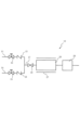
- FIG. 1 is a block diagram of a reaction apparatus 10 in the first embodiment.
- the reaction apparatus 10 includes a reaction vessel 20 through which source gas flows.
- the reaction vessel 20 is connected to a merging pipe 17 to which the two pipes 11 and 14 are connected.
- the pipe 11 is a pipe to which the first raw material gas is supplied, and a control valve 12 and a check valve 13 are arranged in this order from upstream to downstream.
- the pipe 14 is a pipe to which the second source gas is supplied, and a control valve 15 and a check valve 16 are arranged in this order from upstream to downstream.
- a gate valve 18 is arranged in the confluence pipe 17.
- the first and second raw material gases are set to the optimum mixing ratio through control valves 12 and 15, respectively, and the mixed gas (raw material gas) in which the two raw material gases are mixed is passed through the gate valve 18 and into the reaction vessel 20. Supplied.
- the first raw material gas is hydrogen and the second raw material gas is carbon dioxide.
- the reaction vessel 20 is set to an appropriate pressure and heated by a heater 27 to produce methane (methanation) represented by the chemical reaction formula: CO 2 +4H 2 ⁇ CH 4 +2H 2 O.
- the product is cooled to ice temperature by a condenser 28 connected downstream of the reaction vessel 20 and separated into methane-containing gas and water.
- the methane-containing gas may include hydrogen and carbon dioxide, which are raw material gases.
- Methanation is an example of a chemical reaction that occurs in the reaction device 10, and is not limited to this.
- the following chemical reactions can be caused in the reaction apparatus 10.
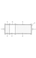
- FIG. 2 is a cross-sectional view of the reaction device 10.
- the arrow shown in FIG. 2 indicates the direction in which the raw material gas flows through the reaction vessel 20 (the same applies to FIGS. 4 to 6).
- the reaction vessel 20 contains catalysts 24 and 26 and a low-activity catalyst 25.
- the reactor 10 includes a first section 21, a second section 22, and a third section 23 in order along the flow direction of the raw material gas (from upstream to downstream).
- the first part 21 and the third part 23 include catalysts 24 and 26, respectively.
- the second portion 22 includes a low-activity catalyst 25 whose catalytic activity is lower than that of the catalysts 24 and 26.
- the catalysts 24 and 26 and the low-activity catalyst 25 lower the activation energy of the chemical reaction and facilitate the progress of the chemical reaction.
- Low catalytic activity means that the degree to which the activation energy of a chemical reaction is lowered is small.
- the first part 21, the second part 22, and the third part 23 are formed by tightening the flanges of pipes with the same inner diameter with bolts or the like, in which the catalyst 24, the low-activity catalyst 25, and the catalyst 26 are arranged, respectively. are connected to each other by.
- the catalyst 24, the low-activity catalyst 25, and the catalyst 26 are arranged, respectively. are connected to each other by.
- catalysts suitable for various chemical reactions can be used without restriction.
- the catalysts 24, 26 and the low-activity catalyst 25 include powders, pellets, or porous structures in which particles are supported on a carrier.
- the carrier include powders, pellets, or porous structures of oxides containing one or more of alumina, silica, magnesia, titania, zirconia, niobia, silica/alumina, zeolite, and calcium phosphate.
- the porous structure has air permeability through which raw material gas can pass. Further, the raw material gas passes through the gaps between the powder and the pellets.
- the particles supported on the carrier include metals containing one or more of Fe, Co, Ni, Cu, Ru, Rh, Pd, Ag, Ir, Pt, and Au. If the materials and particle diameters of the carrier and particles are the same, the catalyst activity is proportional to the surface area of the particles supported by the carrier, so the surface area of the particles supported by the carrier should be smaller than the catalysts 24 and 26. A low activity catalyst 25 is obtained.
- a low-activity catalyst 25 can be obtained by mixing inert particles that do not have catalytic activity with the catalysts 24, 26 and reducing the amount of the catalysts 24, 26 contained in the given amount.
- the inert particles include powders or pellets of oxides containing one or more of alumina, silica, magnesia, titania, zirconia, niobia, silica-alumina, zeolite, and calcium phosphate.
- the raw material gas containing hydrogen and carbon dioxide When the raw material gas containing hydrogen and carbon dioxide is passed through the reaction vessel 20, the raw material gas passes through the first part 21, the second part 22, and the third part 23 in order, and a chemical reaction that produces methane and water progresses. do.
- FIG. 3 is a diagram showing the relationship between each part of the reaction apparatus 10 and temperature.
- a plurality of thermocouples are arranged at the center of gravity of the cross section of the reaction field (collection of catalysts) in the first part 21, second part 22, and third part 23 along the direction in which the raw material gas flows. This is the result of recording the temperature detected by each thermocouple.
- the reaction apparatus 10 was not divided into the first part 21, the second part 22, and the third part 23, but the catalyst 24 of the first part 21 was placed throughout the reaction vessel 20, and the temperature was similarly recorded. This is the result.
- the temperature increases in the first part 21, the temperature decreases in the second part 22, and the temperature increases in the third part 23.
- the catalytic activity of the low-activity catalyst 25 is lower than that of the catalyst 24, and the degree of lowering the activation energy is smaller than in the first part 21. Therefore, the reaction rate is lower than that in the first part 21, and the temperature decreases.
- the catalytic activity of the catalyst 26 is higher than that of the low-activity catalyst 25, and the degree of lowering the activation energy is greater than in the second part 22, so the reaction rate is higher than that in the second part 22, resulting in a reaction. Heat increases the temperature.
- the maximum temperature of the reaction field is higher than in the example due to the chemical reaction (exothermic reaction) that generates methane and water from the raw material gas.
- the temperatures of the catalysts 24, 26 and the low-activity catalyst 25, which rise due to chemical reactions can be reduced, so deterioration of the catalyst can be reduced.
- the catalytic activity of the catalyst 24 in the first part 21 is the same as the catalytic activity of the catalyst 26 in the third part 23 or lower than the catalytic activity of the catalyst 26 in the third part 23 .
- the thickness of the first part 21 in the flow direction of the raw material gas is smaller than the thickness of the third part 23 in the flow direction of the raw material gas. Therefore, even if the catalytic activity of the catalyst 24 in the first part 21 is the same as the catalytic activity of the catalyst 26 in the third part 23, compared to the case where the thickness of the first part 21 is greater than the thickness of the third part 23, The temperature of the first part 21 due to reaction heat can be reduced. Therefore, deterioration of the catalyst 24 can be reduced.
- the thickness of the second part 22 in the direction of flow of raw material gas is smaller than the thickness of third part 23 in the direction of flow of raw material gas. Therefore, compared to the case where the thickness of the second part 22 is greater than the thickness of the third part 23, the total length of the reaction vessel 20 can be made smaller.
- the thickness of the second part 22 in the direction of flow of raw material gas is greater than the thickness of first part 21 in the direction of flow of raw material gas. Therefore, the heat insulation properties of the low-activity catalyst 25 disposed between the first part 21 and the third part 23 can be ensured.
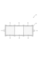
- FIG. 4 is a sectional view of the reaction device 30 in the second embodiment.
- the reactor 30 includes a first part 31, a second part 32, and a third part 33 in this order along the flow direction of the raw material gas.
- the reaction vessel 20 contains catalysts 34, 36 and an inert body 35.
- the first part 31 and the third part 33 include catalysts 34 and 36, respectively.
- the catalysts 34 and 36 lower the activation energy of the chemical reaction and facilitate the progress of the chemical reaction.
- the second part 32 contains an inert body 35 without catalytic activity. Having no catalytic activity means that the inert body 35 does not have the function of lowering the activation energy of a chemical reaction.
- Examples of the inert body 35 include powders, pellets, or porous structures of oxides containing one or more of alumina, silica, magnesia, titania, zirconia, niobia, silica/alumina, zeolite, and calcium phosphate.
- the porous structure has air permeability through which raw material gas can pass. Further, the raw material gas passes through the gaps between the powder and the pellets.
- the raw material gas containing hydrogen and carbon dioxide passes through the reaction vessel 20, the raw material gas passes through the first part 31, the second part 32, and the third part 33 in order, and a chemical reaction that produces methane and water progresses. do.
- the inert body 35 has no catalytic activity and the degree of lowering the activation energy is smaller than that in the first part 31, so the reaction rate is lower than that in the first part 31 and the temperature is lowered. Since the third part 33 lowers the activation energy to a greater degree than the second part 32 by the catalyst 36, the reaction rate is higher than that of the second part 32, and the temperature increases due to reaction heat.
- the heat of reaction in the third part 33 does not become so large.
- the second part 32 is interposed between the third part 33 and the first part 31, the heat of the third part 33 is difficult to be transmitted to the first part 31, and the temperature of the first part 31 does not become so high. Therefore, deterioration of the catalysts 34 and 36 can be reduced.
- the catalytic activity of the catalyst 34 in the first part 31 is the same as the catalytic activity of the catalyst 36 in the third part 33 or lower than the catalytic activity of the catalyst 36 in the third part 33.
- the thickness of the first part 31 in the flow direction of the raw material gas is smaller than the thickness of the third part 33 in the flow direction of the raw material gas.
- the thickness of the second part 32 in the direction of flow of raw material gas is smaller than the thickness of third part 33 in the direction of flow of raw material gas.
- the thickness of the second part 32 in the direction of flow of raw material gas is smaller than the thickness of first part 31 in the direction of flow of raw material gas. Therefore, compared to the case where the thickness of the second part 32 is greater than the thickness of the first part 31, the total length of the reaction vessel 20 can be made smaller.
- FIG. 5 is a sectional view of the reaction device 40 in the third embodiment.
- the reactor 40 includes a first part 41, a second part 42, and a third part 43 in this order along the flow direction of the raw material gas.
- the reaction vessel 20 contains catalysts 44, 46 and a low-activity catalyst 45.
- the first part 41 and the third part 43 include catalysts 44 and 46, respectively.
- the catalytic activity of catalyst 44 is lower than that of catalyst 46.
- the second portion 42 includes a low-activity catalyst 45 whose catalytic activity is lower than that of the catalysts 44 and 46.
- the raw material gas containing hydrogen and carbon dioxide When the raw material gas containing hydrogen and carbon dioxide is passed through the reaction vessel 20, the raw material gas sequentially passes through the first part 41, the second part 42, and the third part 43, and a chemical reaction that produces methane and water progresses. do.
- the catalytic activity of the low-activity catalyst 45 In the second part 42, the catalytic activity of the low-activity catalyst 45 is lower than that of the catalyst 44, and the degree of lowering the activation energy is smaller than in the first part 41. Therefore, the reaction rate is lower than that in the first part 41, and the temperature decreases. Since the third part 43 lowers the activation energy to a greater degree than the second part 42 by the catalyst 46, the reaction rate is higher than that of the second part 42, and the temperature increases due to reaction heat.
- the heat of reaction in the third part 43 does not become so large.
- the second part 42 is interposed between the third part 43 and the first part 41, the heat of the third part 43 is difficult to be transmitted to the first part 41, and the temperature of the first part 41 does not become so high. Therefore, deterioration of the catalysts 44, 46 and the low-activity catalyst 46 can be reduced.
- the thickness of the first part 41 in the direction of flow of the raw material gas is the same as the thickness of the third part 43, but the catalytic activity of the catalyst 44 in the first part 41 is lower than the catalytic activity of the catalyst 46 in the third part 43. , it is possible to prevent the reaction heat in the first part 41 from becoming excessive.
- FIG. 6 is a sectional view of a reaction device 50 in the fourth embodiment.
- the reactor 50 includes a first part 51, a second part 52, and a third part 53 in this order along the flow direction of the raw material gas.
- the first part 51 and the third part 53 include catalysts 54 and 57, respectively.
- the second part 52 includes a pipe 55 that connects the first part 51 and the third part 53, and a condenser 56 disposed in the pipe 55.
- the first part 51 and the third part 53 are set to an appropriate pressure and heated by a heater (not shown). No heater is arranged around the condenser 56.
- the second part 52 is interposed between the third part 53 and the first part 51, the heat of the third part 53 is difficult to be transmitted to the first part 51, and the temperature of the first part 51 does not become so high. Therefore, deterioration of the catalysts 54 and 57 can be reduced.
- the condenser 56 is disposed in the pipe 55 and no heater is disposed around the condenser 56, the second part The section 52 can be cooled.
- the catalytic activity of the catalyst 54 in the first part 51 is the same as the catalytic activity of the catalyst 57 in the third part 53, or lower than the catalytic activity of the catalyst 57 in the third part 53.
- the thickness of the first part 51 in the flow direction of the raw material gas is smaller than the thickness of the third part 53 in the flow direction of the raw material gas. Therefore, even if the catalytic activity of the catalyst 54 in the first part 51 is the same as the catalytic activity of the catalyst 57 in the third part 53, compared to the case where the thickness of the first part 51 is greater than the thickness of the third part 53, The temperature of the first part 51 due to reaction heat can be reduced. Therefore, deterioration of the catalyst 54 can be reduced.
- the product of the reaction in the first part 51 is cooled to ice temperature by the condenser 56 disposed in the pipe 55 of the second part 52, and water is separated. Since the water vapor supplied to the third part 53 through the second part 52 can be reduced, the reaction rate in the third part 53 can be increased.
- first portions 21, 31, 41, the second portions 22, 32, 42, and the third portions 23, 33, 43 have the same inner diameter, but the invention is not necessarily limited to this. It is of course possible to make the inner diameters of the first part 21, 31, 41, the second part 22, 32, 42, and the third part 23, 33, 43 different.
- the present invention is not necessarily limited to this.
- a heater may be placed around the condenser 56 because the temperature rise in the second section 52 caused by the heater can be reduced.
- the second part 52 includes the condenser 56, but the present invention is not necessarily limited to this. It is of course possible to omit the condenser 56. This is because by connecting the first part 51 and the third part 53 with the pipe 55, the reaction rate in the second part 52 can be made smaller than the reaction rate in the first part 51 and the third part 53.
- the condenser 56 is disposed in the pipe 55 provided in the second part 52, but the present invention is not necessarily limited to this.
- the condenser 56 it is of course possible to arrange in the pipe 55 a low-activity catalyst having a lower catalytic activity than the catalysts 54 and 57, or an inert body with no catalytic activity.
Landscapes
- Chemical & Material Sciences (AREA)
- Organic Chemistry (AREA)
- Chemical Kinetics & Catalysis (AREA)
- Engineering & Computer Science (AREA)
- General Chemical & Material Sciences (AREA)
- Oil, Petroleum & Natural Gas (AREA)
- Devices And Processes Conducted In The Presence Of Fluids And Solid Particles (AREA)
- Physical Or Chemical Processes And Apparatus (AREA)
Priority Applications (3)
| Application Number | Priority Date | Filing Date | Title |
|---|---|---|---|
| EP23807394.4A EP4527825A1 (en) | 2022-05-17 | 2023-04-25 | Reaction device |
| CN202380031400.6A CN118973698A (zh) | 2022-05-17 | 2023-04-25 | 反应装置 |
| US18/851,815 US20250214052A1 (en) | 2022-05-17 | 2023-04-25 | Reaction device |
Applications Claiming Priority (2)
| Application Number | Priority Date | Filing Date | Title |
|---|---|---|---|
| JP2022-080745 | 2022-05-17 | ||
| JP2022080745A JP7713907B2 (ja) | 2022-05-17 | 2022-05-17 | 反応装置 |
Publications (1)
| Publication Number | Publication Date |
|---|---|
| WO2023223783A1 true WO2023223783A1 (ja) | 2023-11-23 |
Family
ID=88835027
Family Applications (1)
| Application Number | Title | Priority Date | Filing Date |
|---|---|---|---|
| PCT/JP2023/016259 Ceased WO2023223783A1 (ja) | 2022-05-17 | 2023-04-25 | 反応装置 |
Country Status (5)
| Country | Link |
|---|---|
| US (1) | US20250214052A1 (https=) |
| EP (1) | EP4527825A1 (https=) |
| JP (1) | JP7713907B2 (https=) |
| CN (1) | CN118973698A (https=) |
| WO (1) | WO2023223783A1 (https=) |
Cited By (1)
| Publication number | Priority date | Publication date | Assignee | Title |
|---|---|---|---|---|
| US12325674B1 (en) * | 2024-03-15 | 2025-06-10 | General Galactic Technologies Corporation | Modular system for renewable fuel generation |
Citations (5)
| Publication number | Priority date | Publication date | Assignee | Title |
|---|---|---|---|---|
| JPH0357906B2 (https=) * | 1982-08-02 | 1991-09-03 | Amoco Corp | |
| JP2002143675A (ja) * | 2000-09-04 | 2002-05-21 | Kawasaki Heavy Ind Ltd | 反応器並びに該反応器に用いる触媒及びその製造方法 |
| JP2009534184A (ja) * | 2006-04-27 | 2009-09-24 | ビーエーエスエフ ソシエタス・ヨーロピア | 調節体層使用下での気相酸化法 |
| JP2015124217A (ja) * | 2013-12-27 | 2015-07-06 | 株式会社日立製作所 | メタン製造方法並びにメタン製造装置及びこれを用いたガス化システム |
| JP2018114432A (ja) | 2017-01-16 | 2018-07-26 | 株式会社Ihi | 反応装置 |
-
2022
- 2022-05-17 JP JP2022080745A patent/JP7713907B2/ja active Active
-
2023
- 2023-04-25 EP EP23807394.4A patent/EP4527825A1/en active Pending
- 2023-04-25 CN CN202380031400.6A patent/CN118973698A/zh active Pending
- 2023-04-25 WO PCT/JP2023/016259 patent/WO2023223783A1/ja not_active Ceased
- 2023-04-25 US US18/851,815 patent/US20250214052A1/en active Pending
Patent Citations (5)
| Publication number | Priority date | Publication date | Assignee | Title |
|---|---|---|---|---|
| JPH0357906B2 (https=) * | 1982-08-02 | 1991-09-03 | Amoco Corp | |
| JP2002143675A (ja) * | 2000-09-04 | 2002-05-21 | Kawasaki Heavy Ind Ltd | 反応器並びに該反応器に用いる触媒及びその製造方法 |
| JP2009534184A (ja) * | 2006-04-27 | 2009-09-24 | ビーエーエスエフ ソシエタス・ヨーロピア | 調節体層使用下での気相酸化法 |
| JP2015124217A (ja) * | 2013-12-27 | 2015-07-06 | 株式会社日立製作所 | メタン製造方法並びにメタン製造装置及びこれを用いたガス化システム |
| JP2018114432A (ja) | 2017-01-16 | 2018-07-26 | 株式会社Ihi | 反応装置 |
Cited By (1)
| Publication number | Priority date | Publication date | Assignee | Title |
|---|---|---|---|---|
| US12325674B1 (en) * | 2024-03-15 | 2025-06-10 | General Galactic Technologies Corporation | Modular system for renewable fuel generation |
Also Published As
| Publication number | Publication date |
|---|---|
| JP2023169563A (ja) | 2023-11-30 |
| EP4527825A1 (en) | 2025-03-26 |
| JP7713907B2 (ja) | 2025-07-28 |
| US20250214052A1 (en) | 2025-07-03 |
| CN118973698A (zh) | 2024-11-15 |
Similar Documents
| Publication | Publication Date | Title |
|---|---|---|
| KR102683554B1 (ko) | 합성 가스 제조를 위한 시스템 및 방법 | |
| US4981676A (en) | Catalytic ceramic membrane steam/hydrocarbon reformer | |
| US7462209B2 (en) | Reactor for performing a steam reforming reaction and a process to prepare synthesis gas | |
| Sehested et al. | Activity and stability of molybdenum carbide as a catalyst for CO2 reforming | |
| US20130015405A1 (en) | Isothermal reactor for partial oxidation of methane | |
| KR20200097755A (ko) | 탄화수소 가스를 개질하기 위한 방법 및 시스템 | |
| JP2020124665A (ja) | 気相反応の触媒反応器および触媒反応方法 | |
| CA2786519C (en) | Apparatus and method for adiabatic methane conversion | |
| WO2023223783A1 (ja) | 反応装置 | |
| RU2674971C1 (ru) | Аппарат и способ получения водородсодержащего газа | |
| JP2013517923A (ja) | 触媒反応装置処理方法 | |
| CN113795330B (zh) | 高温反应器容器、设备和方法 | |
| JP5159213B2 (ja) | 水性ガスの製造方法 | |
| JP2023169563A5 (https=) | ||
| RU2796425C1 (ru) | Реактор синтез-газа и способ получения синтез-газа в таком реакторе | |
| EP4674525A1 (en) | Reactor | |
| CA2405932A1 (en) | Process for the selective oxidation of carbon monoxide | |
| US7008597B1 (en) | Catalytic reactor | |
| JP7843719B2 (ja) | メタネーション反応装置及びメタネーション反応方法 | |
| KR101594797B1 (ko) | 유동층 가스화 반응기 | |
| JP2025110559A (ja) | 反応装置 | |
| US7491380B2 (en) | Catalytic reactor | |
| TW201350433A (zh) | 氫氣之生成方法及生成裝置 | |
| EA051223B1 (ru) | Корпус высокотемпературного реактора, установка и способ | |
| BR112021021129B1 (pt) | Vaso de reação de alta temperatura, planta e método |
Legal Events
| Date | Code | Title | Description |
|---|---|---|---|
| 121 | Ep: the epo has been informed by wipo that ep was designated in this application |
Ref document number: 23807394 Country of ref document: EP Kind code of ref document: A1 |
|
| WWE | Wipo information: entry into national phase |
Ref document number: 18851815 Country of ref document: US Ref document number: 202380031400.6 Country of ref document: CN |
|
| WWE | Wipo information: entry into national phase |
Ref document number: 202417073492 Country of ref document: IN |
|
| WWE | Wipo information: entry into national phase |
Ref document number: 2023807394 Country of ref document: EP |
|
| NENP | Non-entry into the national phase |
Ref country code: DE |
|
| ENP | Entry into the national phase |
Ref document number: 2023807394 Country of ref document: EP Effective date: 20241217 |
|
| WWP | Wipo information: published in national office |
Ref document number: 18851815 Country of ref document: US |