WO2023223495A1 - 手術器具 - Google Patents
手術器具 Download PDFInfo
- Publication number
- WO2023223495A1 WO2023223495A1 PCT/JP2022/020810 JP2022020810W WO2023223495A1 WO 2023223495 A1 WO2023223495 A1 WO 2023223495A1 JP 2022020810 W JP2022020810 W JP 2022020810W WO 2023223495 A1 WO2023223495 A1 WO 2023223495A1
- Authority
- WO
- WIPO (PCT)
- Prior art keywords
- shaft
- housing
- flush port
- cleaning liquid
- surgical instrument
- Prior art date
- Legal status (The legal status is an assumption and is not a legal conclusion. Google has not performed a legal analysis and makes no representation as to the accuracy of the status listed.)
- Ceased
Links
Images





Classifications
-
- A—HUMAN NECESSITIES
- A61—MEDICAL OR VETERINARY SCIENCE; HYGIENE
- A61B—DIAGNOSIS; SURGERY; IDENTIFICATION
- A61B18/00—Surgical instruments, devices or methods for transferring non-mechanical forms of energy to or from the body
- A61B18/04—Surgical instruments, devices or methods for transferring non-mechanical forms of energy to or from the body by heating
- A61B18/12—Surgical instruments, devices or methods for transferring non-mechanical forms of energy to or from the body by heating by passing a current through the tissue to be heated, e.g. high-frequency current
- A61B18/14—Probes or electrodes therefor
- A61B18/1442—Probes having pivoting end effectors, e.g. forceps
-
- A—HUMAN NECESSITIES
- A61—MEDICAL OR VETERINARY SCIENCE; HYGIENE
- A61B—DIAGNOSIS; SURGERY; IDENTIFICATION
- A61B90/00—Instruments, implements or accessories specially adapted for surgery or diagnosis and not covered by any of the groups A61B1/00 - A61B50/00, e.g. for luxation treatment or for protecting wound edges
- A61B90/70—Cleaning devices specially adapted for surgical instruments
-
- A—HUMAN NECESSITIES
- A61—MEDICAL OR VETERINARY SCIENCE; HYGIENE
- A61B—DIAGNOSIS; SURGERY; IDENTIFICATION
- A61B34/00—Computer-aided surgery; Manipulators or robots specially adapted for use in surgery
- A61B34/70—Manipulators specially adapted for use in surgery
- A61B34/71—Manipulators operated by drive cable mechanisms
-
- A—HUMAN NECESSITIES
- A61—MEDICAL OR VETERINARY SCIENCE; HYGIENE
- A61B—DIAGNOSIS; SURGERY; IDENTIFICATION
- A61B18/00—Surgical instruments, devices or methods for transferring non-mechanical forms of energy to or from the body
- A61B2018/0091—Handpieces of the surgical instrument or device
-
- A—HUMAN NECESSITIES
- A61—MEDICAL OR VETERINARY SCIENCE; HYGIENE
- A61B—DIAGNOSIS; SURGERY; IDENTIFICATION
- A61B18/00—Surgical instruments, devices or methods for transferring non-mechanical forms of energy to or from the body
- A61B18/04—Surgical instruments, devices or methods for transferring non-mechanical forms of energy to or from the body by heating
- A61B18/12—Surgical instruments, devices or methods for transferring non-mechanical forms of energy to or from the body by heating by passing a current through the tissue to be heated, e.g. high-frequency current
- A61B18/14—Probes or electrodes therefor
- A61B18/1442—Probes having pivoting end effectors, e.g. forceps
- A61B2018/1452—Probes having pivoting end effectors, e.g. forceps including means for cutting
-
- A—HUMAN NECESSITIES
- A61—MEDICAL OR VETERINARY SCIENCE; HYGIENE
- A61B—DIAGNOSIS; SURGERY; IDENTIFICATION
- A61B90/00—Instruments, implements or accessories specially adapted for surgery or diagnosis and not covered by any of the groups A61B1/00 - A61B50/00, e.g. for luxation treatment or for protecting wound edges
- A61B90/08—Accessories or related features not otherwise provided for
- A61B2090/0813—Accessories designed for easy sterilising, i.e. re-usable
-
- A—HUMAN NECESSITIES
- A61—MEDICAL OR VETERINARY SCIENCE; HYGIENE
- A61B—DIAGNOSIS; SURGERY; IDENTIFICATION
- A61B2218/00—Details of surgical instruments, devices or methods for transferring non-mechanical forms of energy to or from the body
- A61B2218/001—Details of surgical instruments, devices or methods for transferring non-mechanical forms of energy to or from the body having means for irrigation and/or aspiration of substances to and/or from the surgical site
- A61B2218/002—Irrigation
-
- A—HUMAN NECESSITIES
- A61—MEDICAL OR VETERINARY SCIENCE; HYGIENE
- A61B—DIAGNOSIS; SURGERY; IDENTIFICATION
- A61B34/00—Computer-aided surgery; Manipulators or robots specially adapted for use in surgery
- A61B34/30—Surgical robots
Definitions
- the present disclosure relates to surgical instruments.
- a surgical instrument includes a cartridge having an internal space, a cylindrical shaft extending from the cartridge, and an end effector such as forceps provided at the tip of the shaft. Surgical instruments are cleaned and sterilized before or after use.
- a method using a cleaning liquid is known as a method for cleaning surgical instruments.
- a method is known in which cleaning is performed by supplying a cleaning liquid to the inside of a cartridge or shaft of a surgical instrument (for example, see Patent Document 1).
- the cleaning liquid is supplied through a flush port provided in the cartridge and a main flush port that is different from the flush port.
- the cleaning liquid supplied through the flush port is supplied inside the cartridge.
- the inside of the cartridge is cleaned with cleaning liquid supplied from the flush port.
- the cleaning liquid supplied through the main flush port is supplied into the shaft through a tube extending from the main flush port.
- the tube is arranged inside the cartridge from the main flush port to the inside of the shaft.
- the inside of the shaft is cleaned with cleaning fluid supplied through the main flush port and tube.
- connection part between the cartridge and the shaft is open.
- the internal space of the cartridge and the internal space of the shaft are in communication.
- Most of the cleaning liquid that has cleaned the inside of the cartridge flows out of the cartridge.
- a portion of the cleaning liquid that has cleaned the inside of the cartridge flows from the interior space of the cartridge into the interior space of the shaft.
- the shaft is not provided with an opening through which the cleaning liquid flows to the outside.
- the cleaning liquid within the shaft often flows out from the shaft via the cartridge. Therefore, the cleaning liquid that has flowed into the shaft from the cartridge needs to be returned to the cartridge from the shaft and then flowed out from the cartridge. For this reason, the time required to clean the surgical instruments tends to be long, and the cleaning efficiency tends to deteriorate.
- the cartridge will also be referred to as a "housing.”
- the present disclosure discloses an example of a surgical instrument that can easily suppress deterioration of cleaning efficiency.
- a surgical instrument includes a housing having an internal space, and a cylindrical shaft extending from the housing and communicating with the internal space.
- the flush port is a through hole through which the cleaning liquid flows from the outside, and at least one opening through which the cleaning liquid flows out to the outside. It is placed between the two.
- the cleaning liquid that flows into the housing from the flush port crosses the central axis of the shaft and easily flows out of the housing from the at least one opening.
- the direction in which the cleaning liquid flows is a direction that crosses the central axis of the shaft.
- the component of the flow toward the inside of the shaft tends to be smaller than the component of the flow toward the at least one opening. In other words, the flow direction of the cleaning liquid is less likely to flow from the interior space of the housing toward the interior of the shaft.
- the flush port is preferably arranged such that the axis of the flush port extends through a position different from the central axis of the shaft.
- the main direction of the flow of the cleaning liquid flowing from the flush port along its axis tends to be different from the direction toward the inside of the shaft. Therefore, the cleaning liquid supplied into the housing through the flush port becomes difficult to flow into the shaft from the internal space of the housing.
- a positional relationship in which the axis of the flush port extends through a position different from the central axis of the shaft will also be referred to as a torsional positional relationship.
- the flush port is preferably arranged in a region closer to the shaft than the at least one opening in the housing.
- the component in the negative direction of the Z axis (the direction away from the shaft along the central axis of the shaft) tends to increase.
- the cleaning liquid becomes difficult to flow into the shaft from the internal space of the housing.
- a surgical instrument includes a housing having an internal space, and a cylindrical shaft extending from the housing and communicating with the internal space.
- the housing has a flush port that is a through hole through which water flows from the outside, and the flush port is arranged in a region closer to the shaft than the center of the housing in the direction in which the shaft extends.
- the main flow direction of the cleaning liquid supplied from the flush port to the inside of the housing tends to be toward the center of the housing. In other words, the cleaning liquid tends to flow away from the shaft. The cleaning liquid becomes difficult to flow into the shaft from the internal space of the housing.
- the flush port is preferably arranged such that the axis of the flush port extends through a position different from the position where the central axis of the shaft extends.
- the housing has at least one opening through which the cleaning liquid flows to the outside, and the at least one opening is located between the central axis of the shaft and the flush port. It is preferable that they be placed at positions sandwiching the two.
- the main flow direction of the cleaning liquid tends to be toward the at least one opening. Therefore, the direction in which the cleaning liquid flows tends to be a direction that crosses the central axis of the shaft.
- the component of the flow toward the inside of the shaft tends to be smaller than the component of the flow toward the at least one opening. In other words, the direction in which the cleaning liquid flows is less likely to flow from the interior space of the housing toward the interior of the shaft.
- the flush port is disposed at a position sandwiching the central axis of the shaft between the flush port and the at least one opening, so that the flow of the cleaning fluid is directed from the internal space of the housing toward the interior of the shaft. This has the effect of easily suppressing deterioration of cleaning efficiency.
- the flush port is arranged in an area closer to the shaft than the center of the housing in the direction in which the shaft extends, so that the flow direction of the cleaning fluid is directed from the internal space of the housing to the inside of the shaft. This has the effect of easily suppressing deterioration of cleaning efficiency.
- FIG. 2 is a front view illustrating the configuration of the surgical instrument of the present disclosure.
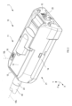
- FIG. 2 is a perspective view illustrating the external configuration of the housing and cover of FIG. 1.
- FIG. 2 is a perspective view illustrating the internal configuration of the cover of FIG. 1.
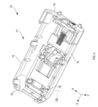
- FIG. 2 is a perspective view illustrating the external configuration of the base of FIG. 1.
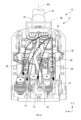
- FIG. 2 is a perspective view illustrating the internal configuration of the base of FIG. 1.
- FIG. FIG. 2 is a sectional view taken along the line VI-VI for explaining the internal structure of the shaft in FIG. 1;
- It is a schematic diagram explaining the flow of the cleaning liquid in a surgical instrument.
- It is a schematic diagram explaining the flow of the cleaning liquid in a housing.
- FIG. 3 is a schematic diagram illustrating another flow of cleaning liquid in a surgical instrument.
- Surgical instrument 10... Housing, 16... Flush port, 16L... Axis line, 26... Tube, 27... Opening, 40... Shaft, 40L... Center axis line
- a surgical instrument 1 according to an embodiment of this disclosure will be described with reference to FIGS. 1 to 8.
- the surgical instrument 1 in this embodiment is an instrument used for surgery, and is an instrument mounted on a master-slave type surgical robot.
- the surgical instrument 1 may be attached to a surgical robot other than a master-slave type.
- the surgical instrument 1 may be an instrument that is not attached to the surgical robot. In FIGS. 1 to 8, the surgical robot is not shown.
- the surgical instrument 1 in this embodiment is an instrument that operates by a driving force transmitted from the outside.
- the driving force is generated in a driving source such as an external actuator, and is transmitted to the surgical instrument 1 via a transmission body such as a wire.
- the surgical instrument 1 is provided with a housing 10 and a shaft 40. Furthermore, the surgical instrument 1 is provided with an end effector 50.
- the X direction and the Y direction are directions extending along a plane orthogonal to the central axis 40L of the shaft 40 extending along the plane of the paper in FIG. 1, and are mutually orthogonal directions.
- a plane of the shaft 40 that is orthogonal to the central axis 40L is orthogonal to the paper plane in FIG.
- the X direction is a direction extending along the mounting surface 22 on the base 21 of the housing 10, and the positive direction of the X direction is a direction toward the front with respect to the plane of the paper in FIG.
- the positive direction of the Y direction is the direction from the base 21 of the housing 10 toward the cover 11.
- the Z direction is a direction parallel to the central axis 40L, and the positive direction of the Z direction is a direction from the housing 10 to the end effector 50.
- the housing 10 is a container having an internal space, and is a part of the surgical instrument 1 that is attached to a surgical robot.
- the housing 10 has a cover 11 and a base 21, as shown in FIG.
- the cover 11 is a member that forms the outer shape of the housing 10 together with the base 21 and forms the internal space of the housing 10.
- the cover 11 has an upper surface 12, a front surface 13, side surfaces 14, 14, and a rear surface 15, as shown in FIGS.
- the upper surface 12 is a surface extending along the ZX plane, and is a surface located on the positive side of the cover 11 in the Y direction.
- the front surface 13 is a surface extending along the XY plane, and is a surface located on the positive side of the cover 11 in the Z direction.
- the side surfaces 14, 14 are surfaces extending along the YZ plane, and are surfaces located on the positive and negative sides of the cover 11 in the X direction.
- the rear surface 15 is a surface extending along the XY plane, and is a surface located on the negative side of the cover 11 in the Z direction.
- the top surface 12, the front surface 13, the side surfaces 14, 14, and the rear surface 15 may be surfaces composed of only a plane, a combination of a plane and a curved surface, or a surface composed only of a curved surface. It may be a surface that is Moreover, the upper surface 12, the front surface 13, the side surfaces 14, 14, and the rear surface 15 may be provided with a structure that protrudes from these surfaces or a structure that is recessed.
- the cover 11 is provided with a flush port 16.
- a flush port 16 is provided on the upper surface 12 of the cover 11.
- the flush port 16 may be provided on the front surface 13 of the cover 11, or may be provided on the side surfaces 14, 14.
- the flush port 16 is arranged at a position sandwiching the central axis 40L between the cover 11 and the base 21. Specifically, it is disposed at a position sandwiching the central axis 40L between it and an opening 27 of the base 21, which will be described later.
- the flush port 16 is a through hole that passes through the cover 11 and is used to supply cleaning liquid from the outside of the housing 10 to its internal space. Flush port 16 passes through top surface 12 of cover 11.
- the flush port 16 is located on the front side of the center of the cover 11. In other words, it is arranged in a region of the cover 11 that is closer to the shaft 40 than the center of the cover 11 . Specifically, the flush port 16 is arranged in a region of the upper surface 12 closer to the shaft 40 than the center in the Z direction.
- the flush port 16 When viewed from the Y direction, the flush port 16 is arranged such that the axis 16L of the flush port 16 extends through a position different from the central axis 40L. In other words, the flush port 16 is arranged at a position different from the position where the central axis 40L extends.
- the flush port 16 when viewed from the Y direction, the flush port 16 is arranged at a position farther away from the central axis 40L on the negative side in the X direction. Note that the flush port 16 may be arranged at a position farther away from the central axis 40L toward the positive side in the X direction.
- the axis 16L is an axis passing through the center of the flush port 16, which is a through hole.
- the central axis of the cylindrical or cylindrical shape is the axis 16L.
- the base 21 is a plate-shaped member that forms the outer shape of the housing 10 together with the cover 11, and is a part of the surgical instrument 1 that is attached to the surgical robot.
- the cover 11 is arranged on the positive side of the base 21 in the Y direction.
- the negative side surface of the base 21 in the Y direction is a mounting surface 22 .
- the mounting surface 22 is a surface for mounting the surgical instrument 1 on the surgical robot, and is a surface that comes into contact with the surgical robot. In FIG. 4, the surgical robot is not shown.
- a shaft attachment portion 23 to which a shaft 40 is attached is provided at the positive end of the base 21 in the Z direction, as shown in FIGS. 1 and 5, for example.
- the shaft attachment portion 23 is provided at a portion of the base 21 that protrudes toward the cover 11 side (in other words, the positive side in the Y direction).
- the shaft attachment portion 23 is provided at the center of the base 21 in the X direction.
- the shaft attachment portion 23 has a cylindrical shape that protrudes toward the positive side in the Z direction.
- the shaft 40 is inserted into and held inside the shaft attachment part 23.
- a main flush port 25 is provided at the negative end of the base 21 in the Z direction.
- the main flush port 25 is a through hole used to supply cleaning liquid from the outside of the housing 10 to the inside of the shaft 40 .
- the main flush port 25 is provided in a portion of the base 21 on the side opposite to the shaft 40 that extends toward the cover 11 side (in other words, the positive side in the Y direction).
- the main flush port 25 is a through hole extending in the Z direction.
- the main flush port 25 may be located at a position off the central axis 40L of the shaft 40, or may be located at a position on the central axis 40L.
- a tube 26 (see FIG. 5) is connected to the main flush port 25.
- the tube 26 is a member used together with the main flush port 25 to supply cleaning liquid to the inside of the shaft 40.
- the tube 26 is a member formed in a cylindrical shape, and is a member formed using a flexible material such as resin.
- the tubes 26 are arranged along the Z direction.
- the tubes 26 may be arranged in a straight line, in a combination of straight lines and curved lines, or in a curved line.
- the tube 26 is arranged between the flush port 16 and the base 21. Specifically, it is arranged between the flush port 16 and an opening 27 of the base 21, which will be described later.
- the tube 26 When viewed from the Y direction, the tube 26 is arranged such that the axis 16L of the flush port 16 extends through a position different from the central axis 40L. Specifically, when viewed from the Y direction, the tube 26 is located at a position further away from the flush port 16 on the positive side in the X direction. Note that the tube 26 may be arranged at a position farther away from the flush port 16 on the negative side in the X direction.
- the negative end of the tube 26 in the Z direction is connected to the main flush port 25.
- a positive end of the tube 26 in the Z direction is disposed inside the shaft 40 .
- the base 21 is provided with three openings 27, 27, 27 and three sliders 28, 28, 28.
- one opening 27 may be explained, but the other two openings 27, 27 also have a similar configuration.
- the opening 27 will also be referred to as a driven groove.
- one slider 28 may be described hereinafter, the other two sliders 28, 28 also have a similar configuration.
- the opening 27 is a through hole that connects the interior space of the housing 10 to the outside.
- the opening 27 is a through hole provided in the base 21, and is a long hole extending in the Z direction.
- the three openings 27, 27, 27 are arranged at equal intervals in the X direction.
- the three openings 27, 27, 27 are arranged in the central region of the base 21.
- the flush port 16 is arranged on the positive side of the three openings 27, 27, 27 in the Z direction. In other words, it is arranged in a region closer to the shaft 40 than the three openings 27, 27, 27.
- the number of openings 27 can be determined based on the joints in the end effector 50 and/or the movement of the forceps, etc. In other words, the number of openings 27 can be determined based on the movement required for the surgical instrument 1 based on the specifications. The number of openings 27 may be greater than or less than three depending on the required specifications.
- the slider 28 is configured to receive driving force from the surgical robot and to transmit the driving force to the end effector 50. Furthermore, the slider 28 has a configuration that allows it to be attached to and detached from the surgical robot.
- the slider 28 is arranged to be movable relative to the base 21. Specifically, the slider 28 is arranged so as to be movable in a linear direction relative to the base 21. Note that the slider 28 may be arranged so as to be rotatable relative to the base 21.
- One slider 28 is arranged in each of the three openings 27, 27, 27, and one slider 28 is arranged so as to be movable in the Z direction inside one opening 27. In other words, the slider 28 is arranged so as to be movable in a linear direction relative to the base 21.
- One slider 28 may be arranged in each of all the openings 27, 27, 27, or only in some of the openings 27.
- the base 21 is provided with three wires 29, 29, 29.
- the wire 29 is configured to transmit the driving force transmitted to the slider 28 to the end effector 50.
- One or two wires 29 are arranged on one slider 28.
- one wire 29 may be explained, but the other two wires 29, 29 have a similar configuration.
- the wire 29 is a long wire made of a conductive material.
- the wire 29 is made of a metal material used in a manipulator of a surgical robot system, such as stainless steel, tungsten, an alloy containing tungsten, or piano wire (for example, as specified in JIS G 3522). It may be formed using
- the shaft 40 is a cylindrical member extending in the Z direction from the base 21 of the housing 10, as shown in FIG.
- the shaft 40 may have a cylindrical shape other than a cylindrical shape.
- An end effector 50 is arranged at the positive end of the shaft 40 in the Z direction.
- the negative end of the shaft 40 in the Z direction is attached to the shaft attachment portion 23 of the base 21, as shown in FIG.
- the inner space of the cylindrical shaft 40 communicates with the inner space of the housing 10 .
- a tube 26, a plurality of wires 29, and electrical wiring 51 are arranged inside the shaft 40. Electrical wiring 51 is used to supply current to end effector 50.
- the tube 26 is arranged near the center inside the shaft 40.
- a plurality of wires 29 and electrical wiring 51 are arranged around the tube 26. Specifically, six wires 29 and one electrical wiring 51 are arranged around the tube 26.
- the end effector 50 shown in FIG. 1 is an instrument used in surgery.
- the end effector 50 has the functions of a monopolar electric scalpel and forceps.
- the end effector 50 may have the function of only one of an electric scalpel and forceps, or may have other functions.
- the end effector 50 has a configuration in which the six wires 29 open and close the forceps and change the direction of the forceps.
- the end effector 50 has a configuration that transmits a high frequency current supplied by an electric wiring 51 to the forceps.
- the cleaning liquid supplied from the flush port 16 flows into the internal space of the housing 10 from the outside, as shown in FIG. At this time, the cleaning liquid flows from the positive side to the negative side in the Y direction. The cleaning liquid spreads and flows through the interior space of the housing 10. The cleaning liquid removes dirt and the like present in the interior space of the housing 10, in other words, cleans dirt and the like present in the interior space of the housing 10.
- the cleaning liquid that has entered the internal space of the housing 10 flows inside the housing 10 toward a location that communicates with the outside of the housing 10. Specifically, it flows toward the plurality of openings 27, 27, 27, the joint between the cover 11 and the base 21, etc.
- the flow path resistance of the portions of the plurality of openings 27, 27, 27 through which the cleaning liquid flows is smaller than the flow path resistance at the joints. Therefore, after the cleaning liquid spreads into the internal space of the housing 10, it easily flows toward the plurality of openings 27, 27, 27, and is difficult to flow in other directions.
- the cleaning liquid that has flowed into the internal space of the housing 10 flows from the flush port 16 toward the negative side in the Y direction and tends to flow toward the negative side in the Z direction.
- the cleaning liquid that has flowed into the internal space of the housing 10 is difficult to flow toward the positive side in the Z direction.
- the shaft 40 In the Z direction, the shaft 40 is arranged on the positive side with respect to the flush port 16. Therefore, the cleaning liquid that has flowed into the internal space of the housing 10 is difficult to flow toward the shaft 40, and therefore is difficult to flow into the interior of the shaft 40.
- a part of the cleaning liquid that has flowed into the internal space of the housing 10 also tends to flow toward the positive side in the X direction.
- the shaft 40 is arranged to extend in the Z direction, and the flow toward the positive side in the X direction is a flow across the shaft 40 and is not a flow toward the inside of the shaft 40. Therefore, the cleaning liquid that has flowed into the internal space of the housing 10 is difficult to flow toward the interior of the shaft 40, and therefore is difficult to flow into the interior of the shaft 40.
- the cleaning liquid flows from the flush port 16 into the internal space of the housing 10 without colliding with other parts or colliding with the tube 26.
- the case in which the cleaning liquid collides with the tube without colliding with other parts will also be referred to as "direct collision.” Therefore, the direction of the flow of the cleaning liquid is unlikely to change toward the inside of the shaft 40 due to direct collision with the tube 26.
- the cleaning liquid guided by the tube 26 flows into the interior of the shaft 40, as shown in FIG.
- the end of the shaft 40 on the positive side in the Z direction is closed, and the cleaning liquid flowing out from the tube 26 in the positive direction in the Z direction changes its flow direction inside the shaft 40 in the negative direction in the Z direction. change.
- the cleaning liquid whose flow direction has been changed removes dirt and the like existing inside the shaft 40. In other words, the inside of the shaft 40 is cleaned.
- the cleaning liquid that has returned to the interior space of the housing 10 flows out of the housing 10 through the plurality of openings 27, 27, 27, and the like.
- the shaft 40 may be provided with a discharge hole 55 for discharging the cleaning liquid to the outside.
- a discharge hole 55 is provided at a location on the shaft 40 where the end effector 50 is attached.
- the location where the discharge hole 55 is provided may be other than the location where the end effector 50 is attached.
- the cleaning liquid flowing into the internal space of the housing 10 from the flush port 16 crosses the central axis 40L of the shaft 40 and flows to the outside of the housing 10 through the plurality of openings 27, 27, 27. Easy to leak.
- the main flow direction of the cleaning liquid tends to be toward the plurality of openings 27, 27, 27.
- the direction in which the cleaning liquid flows tends to cross the central axis 40L of the shaft 40.
- the component of the flow toward the inside of the shaft 40 tends to be smaller than the component of the flow toward the plurality of openings 27, 27, and 27. In other words, the flow direction of the cleaning liquid is less likely to flow from the interior space of the housing 10 to the interior of the shaft 40.
- the cleaning liquid supplied into the housing 10 from the flush port 16 tends to head toward the center of the housing 10.
- the component in the negative direction of the Z axis tends to increase.
- the cleaning liquid tends to flow in a direction away from the shaft 40, so that the cleaning liquid is difficult to flow into the shaft 40 from the internal space of the housing 10.
- the main direction of the flow of cleaning liquid flowing from the flush port 16 along the axis 16L is toward the interior of the shaft 40.
- the direction is likely to be different from the direction shown. Therefore, it becomes difficult for the cleaning liquid to flow into the shaft 40 from the internal space of the housing 10.
Landscapes
- Health & Medical Sciences (AREA)
- Surgery (AREA)
- Life Sciences & Earth Sciences (AREA)
- Engineering & Computer Science (AREA)
- Animal Behavior & Ethology (AREA)
- General Health & Medical Sciences (AREA)
- Biomedical Technology (AREA)
- Heart & Thoracic Surgery (AREA)
- Medical Informatics (AREA)
- Molecular Biology (AREA)
- Nuclear Medicine, Radiotherapy & Molecular Imaging (AREA)
- Veterinary Medicine (AREA)
- Public Health (AREA)
- Physics & Mathematics (AREA)
- Plasma & Fusion (AREA)
- Otolaryngology (AREA)
- Robotics (AREA)
- Oral & Maxillofacial Surgery (AREA)
- Pathology (AREA)
- Surgical Instruments (AREA)
Priority Applications (5)
| Application Number | Priority Date | Filing Date | Title |
|---|---|---|---|
| CN202280096101.6A CN119212642B (zh) | 2022-05-19 | 2022-05-19 | 手术器械 |
| JP2024517018A JP7513341B2 (ja) | 2022-05-19 | 2022-05-19 | 手術器具 |
| PCT/JP2022/020810 WO2023223495A1 (ja) | 2022-05-19 | 2022-05-19 | 手術器具 |
| EP22942700.0A EP4501268B1 (en) | 2022-05-19 | 2022-05-19 | Surgical instrument |
| US18/936,272 US20250057586A1 (en) | 2022-05-19 | 2024-11-04 | Surgical instrument with flush port |
Applications Claiming Priority (1)
| Application Number | Priority Date | Filing Date | Title |
|---|---|---|---|
| PCT/JP2022/020810 WO2023223495A1 (ja) | 2022-05-19 | 2022-05-19 | 手術器具 |
Related Child Applications (1)
| Application Number | Title | Priority Date | Filing Date |
|---|---|---|---|
| US18/936,272 Continuation US20250057586A1 (en) | 2022-05-19 | 2024-11-04 | Surgical instrument with flush port |
Publications (1)
| Publication Number | Publication Date |
|---|---|
| WO2023223495A1 true WO2023223495A1 (ja) | 2023-11-23 |
Family
ID=88835073
Family Applications (1)
| Application Number | Title | Priority Date | Filing Date |
|---|---|---|---|
| PCT/JP2022/020810 Ceased WO2023223495A1 (ja) | 2022-05-19 | 2022-05-19 | 手術器具 |
Country Status (5)
| Country | Link |
|---|---|
| US (1) | US20250057586A1 (https=) |
| EP (1) | EP4501268B1 (https=) |
| JP (1) | JP7513341B2 (https=) |
| CN (1) | CN119212642B (https=) |
| WO (1) | WO2023223495A1 (https=) |
Citations (5)
| Publication number | Priority date | Publication date | Assignee | Title |
|---|---|---|---|---|
| JP2009028156A (ja) * | 2007-07-25 | 2009-02-12 | Terumo Corp | 医療用マニピュレータ及びその洗浄方法 |
| JP2010207260A (ja) * | 2009-03-06 | 2010-09-24 | Top Corp | 鉗子 |
| US20130345701A1 (en) * | 2012-06-26 | 2013-12-26 | Covidien Lp | Surgical instruments with structures to provide access for cleaning |
| US20170128697A1 (en) * | 2015-11-06 | 2017-05-11 | Kardium Inc. | Medical device systems and methods including safety release, lumen fluid-providing mechanisms, or both |
| JP2021186231A (ja) | 2020-05-29 | 2021-12-13 | 株式会社メディカロイド | 手術器具 |
Family Cites Families (7)
| Publication number | Priority date | Publication date | Assignee | Title |
|---|---|---|---|---|
| US8273097B2 (en) * | 2010-04-30 | 2012-09-25 | Medtronic Xomed, Inc. | Powered surgical tissue cutting instrument having an irrigation system |
| US20160193012A1 (en) * | 2013-08-15 | 2016-07-07 | Intuitive Surgical Operations, Inc. | Surgical instruments and methods of cleaning surgical instruments |
| CN119302760A (zh) * | 2016-07-14 | 2025-01-14 | 直观外科手术操作公司 | 器械冲洗系统 |
| US12133775B2 (en) * | 2019-07-09 | 2024-11-05 | Cilag Gmbh International | Adapter for a robotic surgical tool cleaning system |
| US11957523B2 (en) * | 2020-05-29 | 2024-04-16 | Medicaroid Corporation | Surgical instrument |
| CN120585474A (zh) * | 2020-12-28 | 2025-09-05 | 深圳市精锋医疗科技股份有限公司 | 手术器械、从操作设备及手术机器人 |
| CN214805336U (zh) * | 2020-12-28 | 2021-11-23 | 深圳市精锋医疗科技有限公司 | 手术器械、从操作设备及手术机器人 |
-
2022
- 2022-05-19 JP JP2024517018A patent/JP7513341B2/ja active Active
- 2022-05-19 WO PCT/JP2022/020810 patent/WO2023223495A1/ja not_active Ceased
- 2022-05-19 EP EP22942700.0A patent/EP4501268B1/en active Active
- 2022-05-19 CN CN202280096101.6A patent/CN119212642B/zh active Active
-
2024
- 2024-11-04 US US18/936,272 patent/US20250057586A1/en active Pending
Patent Citations (5)
| Publication number | Priority date | Publication date | Assignee | Title |
|---|---|---|---|---|
| JP2009028156A (ja) * | 2007-07-25 | 2009-02-12 | Terumo Corp | 医療用マニピュレータ及びその洗浄方法 |
| JP2010207260A (ja) * | 2009-03-06 | 2010-09-24 | Top Corp | 鉗子 |
| US20130345701A1 (en) * | 2012-06-26 | 2013-12-26 | Covidien Lp | Surgical instruments with structures to provide access for cleaning |
| US20170128697A1 (en) * | 2015-11-06 | 2017-05-11 | Kardium Inc. | Medical device systems and methods including safety release, lumen fluid-providing mechanisms, or both |
| JP2021186231A (ja) | 2020-05-29 | 2021-12-13 | 株式会社メディカロイド | 手術器具 |
Non-Patent Citations (1)
| Title |
|---|
| See also references of EP4501268A4 |
Also Published As
| Publication number | Publication date |
|---|---|
| JP7513341B2 (ja) | 2024-07-09 |
| EP4501268A4 (en) | 2025-05-14 |
| CN119212642B (zh) | 2026-02-06 |
| EP4501268B1 (en) | 2026-03-18 |
| JPWO2023223495A1 (https=) | 2023-11-23 |
| EP4501268A1 (en) | 2025-02-05 |
| CN119212642A (zh) | 2024-12-27 |
| US20250057586A1 (en) | 2025-02-20 |
Similar Documents
| Publication | Publication Date | Title |
|---|---|---|
| EP3856069B1 (en) | Ultrasonic surgical handpiece assembly | |
| EP2027818B1 (en) | Ultrasound probe and ultrasound endoscope including ultrasound probe | |
| JP5639313B2 (ja) | 内視鏡の挿入部の先端硬質部及び、この先端硬質部を用いた内視鏡 | |
| CN113995532B (zh) | 器械冲洗系统 | |
| JP5053872B2 (ja) | 超音波処置装置 | |
| EP3131474A1 (en) | Surgical operating apparatus with temperature control | |
| JP2005131173A (ja) | 内視鏡用外付けチャンネル | |
| ES2535864T3 (es) | Cabezal de soldadura eléctrica por puntos para un robot industrial multiaxial, y el robot que comprende dicho cabezal | |
| WO2023223495A1 (ja) | 手術器具 | |
| US12042209B2 (en) | Insert guide members for surgical instruments, and related devices, systems, and methods | |
| WO2013056121A2 (en) | Electrical charge-dissipating cannula | |
| CN114869450A (zh) | 用于电切镜的电极工具和电切镜 | |
| EP1591071B1 (en) | Ultrasonic treatment device with mist suctioning structure | |
| CN1076650C (zh) | 受变换器激励的器械 | |
| JPWO2006095490A1 (ja) | 内視鏡、光学部材、内視鏡の製造方法 | |
| US20240350210A1 (en) | Surgical instrument | |
| EP1854419A1 (en) | Box joint medical tool apparatus and method of manufacture | |
| US5944657A (en) | Retractor apparatus | |
| EP3932630B1 (en) | Surgical instrument for surgery assistance robot | |
| JP6850056B1 (ja) | 術具 | |
| US12471984B2 (en) | Treatment tool, method of manufacturing treatment tool, and method of reprocessing treatment tool | |
| US20230181205A1 (en) | Treatment tool | |
| JP2004289994A (ja) | イオン交換樹脂成型品及びこれを用いたアクチュエータ素子 | |
| WO2025133783A1 (en) | Articulated robot | |
| JP2025533169A (ja) | 超音波手術システムとの神経モニタリングインテグレーション |
Legal Events
| Date | Code | Title | Description |
|---|---|---|---|
| 121 | Ep: the epo has been informed by wipo that ep was designated in this application |
Ref document number: 22942700 Country of ref document: EP Kind code of ref document: A1 |
|
| ENP | Entry into the national phase |
Ref document number: 2024517018 Country of ref document: JP Kind code of ref document: A |
|
| WWE | Wipo information: entry into national phase |
Ref document number: 2022942700 Country of ref document: EP |
|
| ENP | Entry into the national phase |
Ref document number: 2022942700 Country of ref document: EP Effective date: 20241025 |
|
| WWE | Wipo information: entry into national phase |
Ref document number: 202280096101.6 Country of ref document: CN |
|
| NENP | Non-entry into the national phase |
Ref country code: DE |
|
| WWP | Wipo information: published in national office |
Ref document number: 202280096101.6 Country of ref document: CN |
|
| WWG | Wipo information: grant in national office |
Ref document number: 2022942700 Country of ref document: EP |