WO2023223416A1 - 通信システム、管理制御装置及び制御方法 - Google Patents
通信システム、管理制御装置及び制御方法 Download PDFInfo
- Publication number
- WO2023223416A1 WO2023223416A1 PCT/JP2022/020495 JP2022020495W WO2023223416A1 WO 2023223416 A1 WO2023223416 A1 WO 2023223416A1 JP 2022020495 W JP2022020495 W JP 2022020495W WO 2023223416 A1 WO2023223416 A1 WO 2023223416A1
- Authority
- WO
- WIPO (PCT)
- Prior art keywords
- distributed
- optical path
- switching
- station
- sleep
- Prior art date
- Legal status (The legal status is an assumption and is not a legal conclusion. Google has not performed a legal analysis and makes no representation as to the accuracy of the status listed.)
- Ceased
Links
Images


Classifications
-
- H—ELECTRICITY
- H04—ELECTRIC COMMUNICATION TECHNIQUE
- H04W—WIRELESS COMMUNICATION NETWORKS
- H04W24/00—Supervisory, monitoring or testing arrangements
- H04W24/02—Arrangements for optimising operational condition
-
- H—ELECTRICITY
- H04—ELECTRIC COMMUNICATION TECHNIQUE
- H04W—WIRELESS COMMUNICATION NETWORKS
- H04W36/00—Hand-off or reselection arrangements
- H04W36/16—Performing reselection for specific purposes
- H04W36/22—Performing reselection for specific purposes for handling the traffic
-
- H—ELECTRICITY
- H04—ELECTRIC COMMUNICATION TECHNIQUE
- H04W—WIRELESS COMMUNICATION NETWORKS
- H04W52/00—Power management, e.g. Transmission Power Control [TPC] or power classes
- H04W52/02—Power saving arrangements
- H04W52/0209—Power saving arrangements in terminal devices
- H04W52/0261—Power saving arrangements in terminal devices managing power supply demand, e.g. depending on battery level
- H04W52/0274—Power saving arrangements in terminal devices managing power supply demand, e.g. depending on battery level by switching on or off the equipment or parts thereof
-
- H—ELECTRICITY
- H04—ELECTRIC COMMUNICATION TECHNIQUE
- H04W—WIRELESS COMMUNICATION NETWORKS
- H04W52/00—Power management, e.g. Transmission Power Control [TPC] or power classes
- H04W52/02—Power saving arrangements
- H04W52/0209—Power saving arrangements in terminal devices
- H04W52/0225—Power saving arrangements in terminal devices using monitoring of external events, e.g. the presence of a signal
- H04W52/0229—Power saving arrangements in terminal devices using monitoring of external events, e.g. the presence of a signal where the received signal is a wanted signal
- H04W52/0235—Power saving arrangements in terminal devices using monitoring of external events, e.g. the presence of a signal where the received signal is a wanted signal where the received signal is a power saving command
-
- Y—GENERAL TAGGING OF NEW TECHNOLOGICAL DEVELOPMENTS; GENERAL TAGGING OF CROSS-SECTIONAL TECHNOLOGIES SPANNING OVER SEVERAL SECTIONS OF THE IPC; TECHNICAL SUBJECTS COVERED BY FORMER USPC CROSS-REFERENCE ART COLLECTIONS [XRACs] AND DIGESTS
- Y02—TECHNOLOGIES OR APPLICATIONS FOR MITIGATION OR ADAPTATION AGAINST CLIMATE CHANGE
- Y02D—CLIMATE CHANGE MITIGATION TECHNOLOGIES IN INFORMATION AND COMMUNICATION TECHNOLOGIES [ICT], I.E. INFORMATION AND COMMUNICATION TECHNOLOGIES AIMING AT THE REDUCTION OF THEIR OWN ENERGY USE
- Y02D30/00—Reducing energy consumption in communication networks
- Y02D30/70—Reducing energy consumption in communication networks in wireless communication networks
Definitions
- the present invention relates to a communication system, a management control device, and a control method.
- each base station calculates throughput and autonomously goes to sleep when the throughput exceeds a threshold to save power. There is.
- a terminal connected to a sleeping base station is instructed to handover to the base station with the maximum throughput. This allows the terminal to continue communicating.
- each base station autonomously determines whether or not sleep is necessary, so overall optimization may not be possible and the power saving effect may be limited.
- the present invention aims to provide a technology that can increase the effect of power saving without deteriorating communication quality.
- One aspect of the present invention includes one or more wireless stations that perform wireless communication with one or more terminals, a plurality of distributed stations connected to the one or more wireless stations directly or via another device, and a plurality of distributed stations that perform wireless communication with one or more terminals.
- a cooperation information collection unit that acquires cooperation information indicating the state of communication between the distributed station and the one or more terminals at a predetermined period;
- an optical path switching control unit that controls switching of an optical path between the one or more wireless stations and the plurality of distributed stations when it is determined that switching of the optical path between the one or more wireless stations and the plurality of distributed stations is necessary;
- the communication system includes a sleep control unit that causes a distributed station capable of sleep to enter a sleep state after an optical path is switched.
- One aspect of the present invention provides communication between a plurality of distributed stations that are connected directly or via another device to one or more wireless stations that perform wireless communication with one or more terminals, and the one or more terminals.
- a cooperation information collection unit that acquires cooperation information indicating a state at a predetermined period; and a cooperation information collection unit that performs optical path switching and sleep control between the one or more wireless stations and the plurality of distributed stations based on the cooperation information.
- a management system comprising: an optical path switching control unit that controls switching of an optical path between the distributed station and the distributed station; and a sleep control unit that causes a distributed station that is capable of sleep to enter a sleep state after the optical path has been switched. It is a control device.
- One aspect of the present invention provides communication between a plurality of distributed stations that are connected directly or via another device to one or more wireless stations that perform wireless communication with one or more terminals, and the one or more terminals.
- Cooperation information indicating a state is acquired at a predetermined cycle, and when it is determined that it is necessary to switch the optical path between the one or more wireless stations and the plurality of distributed stations based on the cooperation information.
- a control method that controls switching of an optical path between the one or more wireless stations and the plurality of distributed stations, and causes a distributed station capable of sleep to enter a sleep state after the optical path is switched. It is.
- FIG. 1 is a diagram for explaining the overall configuration and processing outline of a mobile NW system according to the present invention. It is a diagram showing an example of the configuration of a mobile NW system in a first embodiment. It is a flowchart which shows an example of the flow of sleep processing performed by the management control device in a 1st embodiment. It is a flowchart which shows an example of the flow of sleep processing performed by the management control device in a 1st embodiment.
- FIG. 2 is a sequence diagram showing an example of a detailed flow of sleep processing executed by the mobile NW system in the first embodiment. 2 is a flowchart illustrating an example of the flow of sleep cancellation processing executed by the management control device in the first embodiment.
- FIG. 1 is a diagram for explaining the overall configuration and processing outline of a mobile NW system according to the present invention. It is a diagram showing an example of the configuration of a mobile NW system in a first embodiment. It is a flowchart which shows an example of the flow of sleep processing performed by the management control device in a 1st
- FIG. 2 is a sequence diagram illustrating an example of a detailed flow of sleep wakeup processing executed by the mobile NW system in the first embodiment. It is a figure showing the example of composition of the mobile NW system in the modification of a 1st embodiment. It is a figure showing the example of composition of the mobile NW system in the modification of a 1st embodiment.
- FIG. 7 is a sequence diagram showing an example of a detailed flow of sleep processing executed by the mobile NW system in a modification of the first embodiment.
- FIG. 7 is a sequence diagram illustrating an example of a detailed flow of sleep wakeup processing executed by the mobile NW system in a modification of the first embodiment. It is a figure showing the example of composition of the mobile NW system in a 2nd embodiment.
- FIG. 12 is a flowchart illustrating an example of the flow of sleep processing executed by the management control device in the second embodiment. 12 is a flowchart illustrating an example of the flow of sleep processing executed by the management control device in the second embodiment.
- FIG. 7 is a sequence diagram illustrating an example of a detailed flow of sleep processing executed by the mobile NW system in the second embodiment. 12 is a flowchart illustrating an example of the flow of sleep release processing executed by the management control device in the second embodiment.
- FIG. 7 is a sequence diagram showing an example of a detailed flow of sleep wakeup processing executed by the mobile NW system in the second embodiment.
- FIG. 7 is a sequence diagram showing an example of a detailed flow of sleep processing executed by the mobile NW system in a modification of the second embodiment.
- FIG. 12 is a sequence diagram showing an example of a detailed flow of sleep wakeup processing executed by the mobile NW system in a modification of the second embodiment.
- 12 is a flowchart illustrating an example of the flow of sleep processing executed by the management control device in the third embodiment.
- 12 is a flowchart illustrating an example of the flow of sleep processing executed by the management control device in the third embodiment.
- FIG. 7 is a sequence diagram showing an example of a detailed flow of sleep processing executed by the mobile NW system in the third embodiment.
- 12 is a flowchart illustrating an example of a sleep cancellation process executed by the management control device in the third embodiment.
- FIG. 12 is a sequence diagram showing an example of a detailed flow of sleep wakeup processing executed by the mobile NW system in the third embodiment.
- FIG. 12 is a sequence diagram showing an example of a detailed flow of sleep processing executed by the mobile NW system in a modification of the third embodiment.
- FIG. 12 is a sequence diagram showing an example of a detailed flow of sleep wakeup processing executed by the mobile NW system in a modification of the third embodiment. It is a figure showing the example of composition of the mobile NW system in a 4th embodiment.
- 12 is a flowchart illustrating an example of the flow of sleep processing executed by the management control device in the fourth embodiment.
- 12 is a flowchart illustrating an example of the flow of sleep processing executed by the management control device in the fourth embodiment.
- FIG. 12 is a sequence diagram showing an example of a detailed flow of sleep processing executed by the mobile NW system in the fourth embodiment.
- FIG. 12 is a flowchart illustrating an example of the flow of sleep cancellation processing executed by the management control device in the fourth embodiment.
- FIG. 12 is a sequence diagram showing an example of a detailed flow of sleep wakeup processing executed by the mobile NW system in the fourth embodiment.
- FIG. 12 is a sequence diagram showing an example of a detailed flow of sleep processing executed by the mobile NW system in a modification of the fourth embodiment.
- FIG. 13 is a sequence diagram showing an example of a detailed flow of sleep wakeup processing executed by the mobile NW system in a modification of the fourth embodiment.
- FIG. 1 is a diagram for explaining an overview of the overall configuration and processing of a mobile NW system according to the present invention.
- a mobile NW system is an example of a communication system.
- the mobile NW system is, for example, a fifth generation mobile communication system (hereinafter referred to as "5G").
- the mobile NW system includes one or more wireless stations 12 , a switching device 13 , a plurality of distributed stations 14 , an aggregation station 15 , a core device 16 , and a management control device 20 .
- Optical signals are transmitted between the wireless station 12 and the switching device 13, between the switching device 13 and the distributed station 14, between the distributed station 14 and the central station 15, and between the central station 15 and the core device 16. Connected by optical fiber.
- the switching device 13 and the management control device 20 and the distribution station 14 and the management control device 20 are connected by electric wires or optical fibers that transmit electrical signals.
- FIG. 1 shows a case where there are four wireless stations 12 and two distributed stations 14. Note that, although a plurality of switching devices 13 may be provided, the following description will be made using one switching device as an example.
- Each wireless station 12 is equipped with one or more antennas and performs wireless communication with the terminal 11. For example, each wireless station 12 receives a signal transmitted from the terminal 11 and transmits the received signal to the distributed station 14 connected via the switching device 13. Each wireless station 12 transmits the signal received via the switching device 13 to the terminal 11.
- the radio station 12 is, for example, an RU (Radio Unit) in the 5G communication standard.
- the switching device 13 is provided between the wireless station 12 and the distributed station 14.
- the switching device 13 performs optical path switching according to instructions from the management control device 20.
- An optical path is a route for optical signals.
- the switching device 13 switches the connection between the wireless station 12 and the distributed station 14 by switching the optical path.
- the distributed station 14 receives the uplink signal transmitted by the wireless station 12 via the switching device 13.
- the distributed station 14 transmits the downlink signal to the wireless station 12 via the switching device 13.
- the upstream signal is a signal transmitted by the terminal 11, and the downstream signal is a signal destined for the terminal 11.
- Each distributed station 14 transitions to a sleep state according to instructions from the management control device 20.
- the sleep state is a state in which it is possible to save power by stopping some functions.
- the distributed station 14 is, for example, a DU (Distributed Unit) in the 5G communication standard.
- cooperation information is information indicating the state of communication between each distributed station 14 and the terminal 11.
- the cooperation information includes, for example, information regarding the number of terminals 11 accommodated in each distributed station 14 (hereinafter referred to as "number of accommodated terminals").
- the cooperation information includes, for example, the maximum number of terminals that the distributed station 14 can accommodate.
- the maximum number of terminals that the distributed station 14 can accommodate is the maximum number that the distributed station 14 can accommodate.
- the cooperation information includes, for example, information on the wireless station 12 to which the optical path distribution station 14 is connected (hereinafter referred to as "connected wireless station information").
- the cooperation information includes, for example, information regarding the processing load of the distributed station 14 (hereinafter referred to as "processing load information").
- the processing load information may be, for example, information on the memory usage rate of the distributed station 14 or information on the usage rate of the CPU (Central Processing Unit).
- the cooperation information includes, for example, information regarding processing delays for each distributed station 14 (hereinafter referred to as "processing delay information").
- processing delay information information regarding processing delays for each distributed station 14
- delay information information regarding transmission delays between the terminal 11 and each distributed station 14
- the aggregation station 15 aggregates uplink signals transmitted by each distributed station 14.
- the aggregation station 15 distributes downlink signals.
- the aggregation station 15 is, for example, a CU (Centralized Unit) in the 5G communication standard.
- the core device 16 performs signal processing on the upstream signals aggregated by the aggregation station 15.
- the core device 16 transmits a signal obtained as a result of performing signal processing on the upstream signal to an external network.
- Core device 16 receives signals from an external network.
- the core device 16 performs predetermined signal processing on signals received from an external network.
- the core device 16 transmits a signal obtained as a result of performing signal processing on a signal received from an external network to the aggregation station 15 as a downlink signal.
- Signal processing is, for example, the transfer of user data in a UPF (User Plane Function) of the 5G core network.
- UPF User Plane Function
- the management control device 20 acquires cooperation information from the distributed station 14. The management control device 20 determines whether optical path switching and sleep control are necessary based on the acquired cooperation information. The management control device 20 performs optical path switching control processing and sleep control processing when it is determined that optical path switching and sleep control are necessary.
- the optical path switching control process is a process for switching the optical path between the wireless station 12 and the distributed station 14. For example, the management control device 20 instructs the switching device 13 to control switching of the optical path between the wireless station 12 and the distributed station 14.
- the sleep control process is a process that causes the distributed station 14 to execute sleep or cancel sleep.
- the upper diagram in FIG. 1 represents the connection state of the mobile NW system before optical path switching
- the lower diagram in FIG. 1 represents the connection state of the mobile NW system after optical path switching.
- the upper diagram of FIG. 1 shows an example in which wireless stations 12-1 and 12-2 are connected to distributed station 14-1, and wireless stations 12-3 and 12-4 are connected to distributed station 14-2. has been done.
- the management control device 20 determines whether to perform optical path switching control processing based on the cooperation information collected from each distributed station 14.
- the management control device 20 determines to perform the optical path switching control process when there is a distributed station 14 that can transition to the sleep state.
- the distributed station 14 that can enter the sleep state is, for example, the distributed station 14 that does not accommodate the terminal 11.
- the management control device 20 determines not to perform the optical path switching control process when there is no distributed station 14 that can transition to the sleep state.
- the management control device 20 determines to perform the optical path switching control process, it instructs the switching device 13 to switch the optical path.
- the switching device 13 switches the optical path between the wireless station 12 and the distributed station 14 according to instructions from the management control device 20. After completing the optical path switching, the switching device 13 notifies the management control device 20 of the completion of the optical path switching.
- the management control device 20 Upon receiving the notification of completion of optical path switching from the switching device 13, the management control device 20 transmits a sleep permission notification to the distributed station 14 that can transition to the sleep state.
- the sleep permission notification is a signal containing an instruction to cause the distributed station 14 to enter a sleep state. As a result, the distributed station 14 that can go into a sleep state goes into a sleep state.
- the lower diagram in FIG. 1 shows an example in which wireless stations 12-1 to 12-4 are connected to distributed station 14-1, and distributed station 14-2 is in a sleep state.
- the terminal 11 connected to a distributed station 14 that can go into a sleep state is connected to another distributed station 14 based on the cooperation information collected from each distributed station 14. This causes the distributed station 14 that can go into a sleep state to go into a sleep state.
- the distributed station 14 that can transition to a sleep state will be referred to as a switching source distributed station, and the distributed station 14 that will become the new connection destination of the terminal 11 connected to the switching source distributed station will be referred to as a switching destination distributed station.
- FIG. 2 is a diagram showing a configuration example of the mobile NW system 100 in the first embodiment.
- the mobile NW system 100 in the first embodiment includes one or more wireless stations 12, a switching device 13, a plurality of distributed stations 14, an aggregation station 15, a core device 16, and a management control device 20.
- the wireless station 12, switching device 13, distributed station 14, aggregation station 15, and core device 16 have been described with reference to FIG. 1, so their description will be omitted.
- the management control device 20 includes a cooperation information collection section 21, an analysis section 22, and a control section 23.
- the cooperation information collection unit 21 includes an acquisition unit 211.
- the acquisition unit 211 collects cooperation information from the distributed station 14 at a predetermined period.
- the analysis section 22 includes a cooperation information storage section 221 and a real-time analysis section 222.
- the cooperation information storage unit 221 records the collected cooperation information in a predetermined storage device.
- the real-time analysis unit 222 analyzes the state of communication between each distributed station 14 and the terminal 11, such as the amount of change in the number of connected distributed stations 14 per unit time, based on the cooperation information. Specifically, the real-time analysis unit 222 determines whether optical path switching and sleep control are necessary based on the cooperation information.
- the real-time analysis unit 222 determines that optical path switching and sleep control are necessary when all the terminals 11 accommodated by the switching source distributed station can be accommodated in another distributed station 14. In this case, the real-time analysis unit 222 notifies the control unit 23 of information indicating the distributed station 14 to which the optical path is to be switched and information indicating the distributed station 14 to be put to sleep.
- the real-time analysis unit 222 determines that optical path switching and sleep control are necessary when the number of terminals 11 accommodated by the distributed station 14 exceeds the maximum number of terminals accommodated. In this case, the real-time analysis unit 222 notifies the control unit 23 of information indicating the distributed station 14 to which the optical path is to be switched and information indicating the distributed station 14 to be woken from sleep.
- the control unit 23 includes an optical path switching control unit 231 and a sleep control unit 232.
- the optical path switching control unit 231 determines the distributed station 14 to which the optical path is to be switched, based on the analysis result of the real-time analysis unit 322, and instructs the switching device 13 to switch the optical path. For example, the optical path switching control unit 231 determines the distributed station 14 to which the optical path is to be switched, based on the information indicating the distributed station 14 to which the optical path is to be switched, which is notified from the real-time analysis unit 222 .
- the sleep control unit 232 causes the distributed station 14 to execute sleep or cancel sleep based on the analysis result of the real-time analysis unit 322.
- FIG. 3 is a flowchart showing an example of the flow of sleep processing executed by the management control device 20 in the first embodiment.
- the cooperation information includes at least information on the number of terminals accommodated in each distributed station 14 and information on the maximum number of terminals accommodated.
- the process flow in FIG. 3 is repeatedly executed at a predetermined cycle.
- the acquisition unit 211 acquires cooperation information from each distributed station 14 (step S101).
- the acquisition unit 211 stores the acquired cooperation information for each distributed station 14 in the cooperation information storage unit 221 (step S102).
- the real-time analysis unit 222 calculates the number of additional terminals that each distributed station 14 can accommodate based on the cooperation information for each distributed station 14 accumulated in the cooperation information storage unit 221 (step S103).
- the number of terminals that can be additionally accommodated refers to the number of terminals 11 that can be additionally accommodated in addition to the number of terminals that the distributed station 14 currently accommodates.
- the number of additionally accommodable terminals can be obtained by subtracting the number of accommodated terminals from the maximum number of accommodated terminals.
- the real-time analysis unit 222 determines whether the first switching condition is satisfied (step S104).
- the first switching condition is a condition indicating that the optical path between the wireless station 12 and the distributed station 14 needs to be switched. This is more than the number of terminals accommodated by the distributed station 14.
- the real-time analysis unit 222 determines that the first switching condition is satisfied (step S104-YES), it notifies the control unit 23 of an optical path switching instruction and a sleep control instruction.
- the optical path switching control unit 231 instructs the switching device 13 to switch the optical path of the wireless station 12 connected to the switching source distributed station based on the optical path switching instruction notified from the real-time analysis unit 222 (step S105). Specifically, the optical path switching control unit 231 instructs the optical path of the wireless station 12 connected to the switching source distributed station to go toward the switching destination distributed station.
- the sleep control unit 232 transmits a sleep permission notification to the switching source distributed station (step S106). For example, the sleep control unit 232 may transmit a sleep instruction to the switching source distributed station when an optical path switching completion notification is obtained from the wireless station 12 connected to the switching source distributed station and the switching destination distributed station. .
- the optical path switching completion notification is a signal that includes content indicating that optical path switching has been completed. This allows the switching source distributed station to transition to a sleep state.
- step S104 if the real-time analysis unit 222 determines that the first switching condition is not satisfied (step S104-NO), it determines whether there are other distributed stations 14 (step S107).
- the other distributed stations 14 are, for example, distributed stations 14 that have not been compared with the distributed station 14 that is the target of sleep determination.
- step S107-NO the process ends.
- the real-time analysis unit 222 determines that there are other distributed stations 14 (step S107-YES), it selects information on the number of additionally accommodated terminals of the other distributed stations 14 (step S108). The real-time analysis unit 222 executes the process of step S104 again using information on the number of additionally accommodated terminals of the other selected distributed stations 14.
- FIG. 4 is a flowchart showing an example of the flow of sleep processing executed by the management control device 20 in the first embodiment. Note that the process shown in FIG. 4 will be described in more detail with respect to the process shown in FIG.
- the acquisition unit 211 acquires information on the maximum number of accommodating terminals, connected wireless station information, and number of accommodating terminals of each distributed station from each distributed station 14 as cooperation information (step S201).
- the acquisition unit 211 stores the acquired cooperation information for each distributed station 14 in the cooperation information storage unit 221 (step S202).
- the real-time analysis unit 222 calculates the number of additional terminals that each distributed station 14 can accommodate based on the cooperation information for each distributed station 14 accumulated in the cooperation information storage unit 221 (step S203).
- the real-time analysis unit 222 assigns a value of 1 to the constant i (step S204).
- i represents the distributed station 14-i that is the switching destination.
- the distributed station 14-1 becomes the switching destination distributed station.
- i has a value of 1 ⁇ i ⁇ I.
- I is the total number of distributed stations 14.
- the real-time analysis unit 222 assigns the value of (i+1) to k (step S205).
- k represents the distributed station 14-k that is the switching source.
- the distributed station 14-2 becomes the switching source distributed station.
- k has a value of 2 ⁇ k ⁇ K.
- the real-time analysis unit 222 determines whether U i ⁇ u i >u k is satisfied (step S206).
- U i represents the maximum number of terminals accommodated by the distributed station 14-i
- u i represents the number of terminals accommodated by the distributed station 14-i
- u k represents the number of terminals accommodated by the distributed station 14-k.
- the condition indicated by U i ⁇ u i >u k is a specific example of the first switching condition.
- the maximum number of terminals accommodated by the distributed station 14-1 is 1000
- the maximum number of terminals accommodated by the distributed station 14-1 is 100
- the maximum number of terminals accommodated by the distributed station 14-2 is 800
- the number of terminals accommodated by the distributed station 14-2 is 200.
- U 1 ⁇ u 1 >u 2 becomes 900>200, and the first switching condition is satisfied. If the real-time analysis unit 222 determines that the first switching condition (for example, U i - u i > u k ) is satisfied (step S206-YES), the real-time analysis unit 222 sends an optical path switching instruction and a sleep control instruction to the control unit. Notify 23.
- the first switching condition for example, U i - u i > u k
- the optical path switching control unit 231 instructs the switching device 13 to switch the optical path of the wireless station 12 connected to the distributed station 14-k based on the optical path switching instruction notified from the real-time analysis unit 222 (Ste S207). Specifically, the optical path switching control unit 231 switches the optical path of the wireless station 12 connected to the distributed station 14-k (for example, the distributed station 14-2) to the distributed station 14-i (for example, the distributed station 14-2). -1) Instruct to go to the switching destination distributed station.
- the sleep control unit 232 transmits a sleep permission notification to the distributed station 14-k (for example, the distributed station 14-2) (step S208).
- the maximum number of terminals accommodated by the distributed station 14-1 is 1000
- the maximum number of terminals accommodated by the distributed station 14-1 is 500
- the maximum number of terminals accommodated by the distributed station 14-2 is 800
- step S209-YES determines whether i is the maximum value (step S211). If the real-time analysis unit 222 determines that i is the maximum value (step S211-YES), it ends the process.
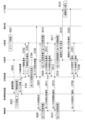
- FIG. 5 is a sequence diagram showing an example of a detailed flow of sleep processing executed by the mobile NW system 100 in the first embodiment.
- the distributed station 14-1 is the switching destination distributed station
- the distributed station 14-2 is the switching source distributed station.
- the explanation will be given by referring to the switching destination distributed station 14-1 and the switching source distributed station 14-2.
- the acquisition unit 211 of the management control device 20 acquires cooperation information from the switching destination distributed station 14-1 and the switching source distributed station 14-2 at a predetermined period (step S301, step S302).
- the acquisition unit 211 stores the acquired collaboration information in the collaboration information storage unit 221.
- the real-time analysis section 222 performs optical path switching and sleep control judgment (step S303).
- the optical path switching and sleep control determination in step S303 is a determination as to whether the first switching condition is satisfied in step S104.
- the real-time analysis unit 222 instructs the optical path switching control unit 231 to perform optical path switching control, and instructs the sleep control unit 232 to perform sleep control.
- the optical path switching control unit 231 notifies the switching device 13 and the aggregation station 15 of the optical path switching destination information (step S304).
- the optical path switching destination information is information regarding the switching destination of the optical path.
- the optical path switching destination information includes information indicating the switching destination distributed station 14-1 as the optical path switching destination.
- the switching device 13 instructs the wireless station 12 connected to the switching source distributed station 14-2 to switch the optical path to the switching destination distributed station 14-1, and is instructed to switch so that the optical path is connected to the wireless station 12 connected to the switching source distributed station 14-2, and the switching source distributed station 14-2 is instructed not to set up an optical path. do.
- the wireless station 12 connected to the switching source distributed station 14-2, the switching destination distributed station 14-1, and the switching source distributed station 14-2 prepare for optical path switching (steps S306, S307, and S308).
- the wireless station 12 connected to the switching source distributed station 14-2, the switching destination distributed station 14-1, and the switching source distributed station 14-2 transmit an optical path switching response notification to the switching device 13 (step S309 , step S310 and step S311).
- the optical path switching response notification is a signal that includes content indicating that optical path switching destination information has been received.
- the switching device 13 When the switching device 13 receives an optical path switching response notification from the wireless station 12 connected to the switching source distributed station 14-2, the switching destination distributed station 14-1, and the switching source distributed station 14-2, the switching device 13 performs switching.
- An optical path switching start notification is transmitted to the wireless station 12 connected to the wireless station 12 connected to the original distributed station 14-2 and the switching destination distributed station 14-1 (step S312).
- the optical path switching start notification is a signal containing a command to start optical path switching.
- the wireless station 12 connected to the switching source distributed station 14-2 and the switching destination distributed station 14-1 switch optical paths in response to receiving the optical path switching start notification (step S313, step S314). Through this process, the optical path of the wireless station 12 connected to the switching source distributed station 14-2 is switched so as to go toward the switching destination distributed station 14-1. That is, the wireless station 12 and the switching destination distributed station 14-1 become communicable.
- the switching destination distributed station 14-1 transmits a path switching request to the core device 16 (step S315).
- the path switching request is a signal that includes content requesting switching of the communication path in the core device 16.
- the core device 16 switches the route in response to receiving the route switching request (step S316).
- the core device 16 transmits a route switching response notification to the switching destination distributed station 14-1 (step S317).
- the path switching response notification is a signal that includes content indicating that switching of the communication path in the core device 16 has been completed.
- the wireless station 12 transmits an optical path switching completion notification to the management control device 20 (step S318).
- the optical path switching completion notification is a signal that includes content indicating that optical path switching has been completed.
- the switching destination distributed station 14-1 transmits an optical path switching completion notification to the management control device 20 (step S319).
- the sleep control unit 232 When the sleep control unit 232 receives the optical path switching completion notification from the destination of the optical path switching start notification, it transmits a sleep permission notification to the switching source distributed station 14-2 (step S320). When the switching source distributed station 14-2 receives the sleep permission notification from the management control device 20, it transmits a sleep response notification to the management control device 20 (step S321).
- the sleep response notification is a signal that includes content indicating that the sleep permission notification has been received. After transmitting the sleep response notification, the switching source distributed station 14-2 shifts to a sleep state (step S322).
- FIG. 6 is a flowchart illustrating an example of the flow of sleep release processing executed by the management control device 20 in the first embodiment.
- the acquisition unit 211 acquires the number of accommodated terminals and information on the sleeping distributed station 14-k from each distributed station 14 as cooperation information (step S401).
- the acquisition unit 211 notifies the analysis unit 22 of the acquired number of accommodated terminals and information on the sleeping distributed station 14-k.
- the real-time analysis unit 222 reads information on the maximum number of terminals accommodated by each distributed station 14 and information on the wireless station 12 that was connected to the sleeping distributed station 14-k from the cooperation information storage unit 221 (step S402).
- the real-time analysis unit 222 calculates the number of additional terminals that each distributed station 14 can accommodate based on the cooperation information for each distributed station 14 accumulated in the cooperation information storage unit 221 (step S403).
- the real-time analysis unit 222 assigns a value of 1 to the constant i (step S404).
- the real-time analysis unit 222 determines whether U i ⁇ u i is satisfied (step S405).
- the condition represented by U i ⁇ u i is a specific example of the first sleep release condition. If the real-time analysis unit 222 determines that the first sleep cancellation condition (for example, U i ⁇ u i ) is satisfied (step S405-YES), the real-time analysis unit 222 cancels the sleep state of the sleeping distributed station 14-k and controls the optical path. It is determined that switching is necessary.
- the real-time analysis unit 222 notifies the control unit 23 of the determination result.
- the sleep control unit 232 transmits an instruction to wake up the sleeping distributed station 14-k based on the determination result (step S406).
- the optical path switching control unit 231 acquires information on the wireless station 12 that was connected to the distributed station 14-k before sleep from the information acquired in the process of step S402.
- the optical path switching control unit 231 instructs the wireless station 12 that was connected to the distributed station 14-k before sleep to change the connection to the distributed station 14-k.
- step S405 if the real-time analysis unit 222 determines that the first sleep release condition (for example, U i ⁇ u i ) is not satisfied (step S405 - NO), it determines whether i is the maximum value or not. is determined (step S408). If the real-time analysis unit 222 determines that i is the maximum value (step S408-YES), it ends the process.
- the first sleep release condition for example, U i ⁇ u i
- step S408-NO if the real-time analysis unit 222 determines that i is not the maximum value (step S408-NO), it adds a value of 1 to the value of i (step S409). After that, the real-time analysis unit 222 executes the process of step S405 again.
- the process in FIG. 6 will be explained using specific numerical values.
- the maximum number of terminals accommodated by the distributed station 14-1 is 1000
- the number of terminals accommodated by the distributed station 14-1 is 800
- the maximum number of terminals accommodated by the distributed station 14-1 is 800. It is assumed that the maximum number of terminals accommodated by the distributed station 14-2 is 800, and the number of terminals accommodated by the distributed station 14-2 is 1000.
- the real-time analysis unit 222 executes the process of step S405 again.
- FIG. 7 is a sequence diagram showing an example of a detailed flow of the sleep wakeup process executed by the mobile NW system 100 in the first embodiment. In the explanation of FIG. 7, it is assumed that the distributed station 14-2 is in a sleep state.
- the distributed station 14-2 is in a sleep state (step S501).
- the acquisition unit 211 of the management control device 20 acquires cooperation information from the distributed station 14-1 at a predetermined period (step S502).
- the acquisition unit 211 stores the acquired collaboration information in the collaboration information storage unit 221.
- the real-time analysis section 222 performs optical path switching and sleep control judgment (step S503).
- the optical path switching and sleep control determination in step S503 is based on whether the sleep release condition is satisfied. Here, it is assumed that the sleep release condition is satisfied.
- the sleep control unit 232 of the management control device 20 transmits a sleep release notification to the distributed station 14-2 (step S504).
- the sleep release notification is a signal that includes content indicating that the sleep state will be released.
- the distributed station 14-2 transmits a sleep release response notification to the management control device 20 (step S505).
- the sleep release response notification is a signal that includes content indicating that the sleep release notification has been received.
- the optical path switching control unit 231 notifies the switching device 13 and the aggregation station 15 of the optical path switching destination information (step S506).
- the switching device 13 is notified of the optical path switching destination information from the management control device 20, it instructs the wireless station 12, the distributed station 14-1, and the distributed station 14-2 to switch the optical path (step S507).
- the wireless station 12, the distributed station 14-1, and the distributed station 14-2 prepare for optical path switching (step S508, step S509, and step S510).
- the wireless station 12, the distributed station 14-1, and the distributed station 14-2 complete the preparation for switching the optical path, they transmit an optical path switching response notification indicating that the preparation for switching is completed to the switching device 13 (step S511, step S512 and step S513).
- the switching device 13 When the switching device 13 receives an optical path switching response notification from the wireless station 12, the distributed station 14-1, and the distributed station 14-2, the switching device 13 switches the wireless station 12, the distributed station 14-1, and the distributed station 14-2.
- An optical path switching start notification is transmitted to (step S514).
- the wireless station 12, the distributed station 14-1, and the distributed station 14-2 switch optical paths in response to receiving the optical path switching start notification (step S515, step S516, and step S517).
- the distributed station 14-1 transmits a path switching request to the core device 16 (step S518).
- the core device 16 switches the route in response to receiving the route switching request (step S519).
- the core device 16 transmits a route switching response notification to the distributed station 14-1 (step S520).
- the wireless station 12 transmits an optical path switching completion notification to the management control device 20 (step S521).
- the distributed station 14-1 transmits an optical path switching completion notification to the management control device 20 (step S522).
- the distributed station 14-2 transmits an optical path switching completion notification to the management control device 20 (step S523).
- one or more wireless stations 12 that perform wireless communication with one or more terminals 11 and a plurality of wireless stations 12 connected to the one or more wireless stations 12 via the switching device 13 a cooperation information collection unit 21 that acquires cooperation information indicating the state of communication between the plurality of distributed stations 14 and one or more terminals 11 at a predetermined period;
- a cooperation information collection unit 21 that acquires cooperation information indicating the state of communication between the plurality of distributed stations 14 and one or more terminals 11 at a predetermined period;
- It includes an optical path switching control section 231 that controls, and a sleep control section 232 that causes a distributed station capable of sleep to enter a sleep state after switching the optical path.
- optical path switching and sleep control are performed while analyzing the load on each distributed station 14. Therefore, it is possible to increase the power saving effect without deteriorating communication quality.
- FIG. 8 is a diagram showing a configuration example of the mobile NW system 100a in Modification 1 of the first embodiment.
- the mobile NW system 100a includes one or more wireless stations 12, a switching device 13, a plurality of distributed stations 14, an aggregation station 15, a core device 16, a management control device 20, and a wireless controller 30a.
- a wireless controller 30a is provided between the management control device 20 and the distributed station 14.
- the wireless controller 30a acquires cooperation information from each distributed station 14 at a predetermined period through wireless communication.
- the wireless controller 30a transmits the acquired cooperation information to the management control device 20 by wireless communication.
- the wireless controller 30a may receive a sleep control instruction from the management control device 20 and transmit it to the switching source distributed station. With this configuration, cooperation information can be collected by wireless communication.
- FIG. 9 is a diagram showing a configuration example of the mobile NW system 100b in the second modification of the first embodiment.
- the mobile NW system 100b includes one or more wireless stations 12, a switching device 13b, a plurality of distributed stations 14, an aggregation station 15, a core device 16, and a management control device 20b.
- the switching device 13b includes a control unit 23, and the management control device 20b does not include a control unit 23.
- the real-time analysis unit 222 of the management control device 20b notifies the switching device 13b of the analysis result. Note that the real-time analysis unit 222 may notify the switching device 13b of the analysis results only when optical path switching and sleep control are performed.
- the control unit 23 of the switching device 13b performs optical path switching control processing and sleep control processing based on the analysis result notified from the management control device 20b.
- FIG. 10 is a sequence diagram showing an example of a detailed flow of sleep processing executed by the mobile NW system 100b in the second modification of the first embodiment.
- the same processes as in FIG. 5 are given the same reference numerals as in FIG. 5, and the description thereof will be omitted.
- the distributed station 14-1 is the switching destination distributed station
- the distributed station 14-2 is the switching source distributed station.
- the explanation will be given by referring to the switching destination distributed station 14-1 and the switching source distributed station 14-2.
- the real-time analysis unit 222 instructs the switching device 13b to perform optical path switching control and sleep control if the first switching condition is satisfied (step S601).
- the switching device 13b receives the instruction transmitted from the management control device 20b.
- the optical path switching control unit 231 of the switching device 13b determines the optical path switching destination from the information included in the received instruction (step S602).
- the optical path switching control unit 231 notifies the aggregation station 15 of the optical path switching destination information (step S603). Thereafter, the optical path switching control unit 231 performs optical path switching for the wireless station 12 connected to the switching source distributed station 14-2, the switching destination distributed station 14-1, and the switching source distributed station 14-2. (Step S604). After that, the processes from step S306 to step S317 are executed.
- the wireless station 12 transmits an optical path switching completion notification to the switching device 13b (step S605). Note that the wireless station 12 may also transmit the optical path switching completion notification to the management control device 20b.
- the switching destination distributed station 14-1 transmits an optical path switching completion notification to the switching device 13b (step S606). Note that the wireless station 12 may also transmit the optical path switching completion notification to the management control device 20b.
- the sleep control unit 232 included in the switching device 13b When the sleep control unit 232 included in the switching device 13b receives the optical path switching completion notification from the destination of the optical path switching start notification, it transmits a sleep permission notification to the switching source distributed station 14-2 (step S607 ). When the switching source distributed station 14-2 receives the sleep permission notification from the switching device 13b, it transmits a sleep response notification to the switching device 13b (step S608). After transmitting the sleep response notification, the switching source distributed station 14-2 shifts to a sleep state (step S322).
- FIG. 11 is a sequence diagram showing an example of a detailed flow of the sleep wakeup process executed by the mobile NW system 100b in the second modification of the first embodiment.
- the same processes as in FIG. 7 are given the same reference numerals as in FIG. 7, and the description thereof will be omitted.
- the distributed station 14-2 is in a sleep state.
- the real-time analysis unit 222 instructs the switching device 13b to perform optical path switching control and sleep control when the sleep release condition is satisfied (step S701).
- the switching device 13b receives the instruction transmitted from the management control device 20b.
- the sleep control unit 232 of the switching device 13b transmits a sleep release notification to the distributed station 14-2 based on the information included in the received instruction (step S702).
- the distributed station 14-2 transmits a sleep release response notification to the switching device 13b (step S703).
- the optical path switching control unit 231 of the switching device 13b determines the optical path switching destination from the information included in the received instruction (step S704).
- the optical path switching control unit 231 of the switching device 13b notifies the aggregation station 15 of the optical path switching destination information (step S705). After that, the processes from step S507 to step S520 are executed.
- the wireless station 12 transmits an optical path switching completion notification to the switching device 13b (step S706).
- the distributed station 14-1 transmits an optical path switching completion notification to the switching device 13b (step S707).
- the distributed station 14-2 transmits an optical path switching completion notification to the switching device 13b (step S708).
- the second embodiment differs in configuration from the first embodiment in that the cooperation information further includes processing load information (for example, memory usage rate information or CPU usage rate information for each distributed station). .
- processing load information for example, memory usage rate information or CPU usage rate information for each distributed station.
- FIG. 12 is a diagram showing a configuration example of a mobile NW system 100c in the second embodiment.
- the mobile NW system 100c in the second embodiment includes one or more wireless stations 12, a switching device 13, a plurality of distributed stations 14, an aggregation station 15, a core device 16, and a management control device 20c.
- the management control device 20c includes a cooperation information collection section 21c, an analysis section 22c, and a control section 23.
- the cooperation information collection unit 21c includes an acquisition unit 211 and a distributed station monitoring unit 212c.
- the distributed station monitoring unit 212c monitors each distributed station 14 and measures the memory usage rate for each distributed station 14.
- the distributed station monitoring unit 212c outputs information on the memory usage rate measured for each distributed station 14 to the analysis unit 22c as cooperation information.
- the analysis section 22c includes a cooperation information storage section 221 and a real-time analysis section 222c.
- the real-time analysis unit 222c analyzes the communication state in the mobile NW system 100c, such as the amount of change in the number of connections of the distributed stations 14 per unit time, based on the cooperation information. Specifically, the real-time analysis unit 222c divides the memory usage rate by the current number of accommodated terminals to roughly estimate the memory usage rate per terminal.
- the real-time analysis unit 222c multiplies the number of accommodated terminals of other distributed stations 14 by the memory usage rate per unit of the target distributed station 14, and determines that the memory usage rate does not exceed 100% and that the When the number of terminals accommodated by the station 14 is smaller than the number of terminals that can be additionally accommodated by the target distributed station 14, optical path switching and sleep are determined.
- FIG. 13 is a flowchart showing an example of the flow of sleep processing executed by the management control device 20c in the second embodiment.
- the same processes as in FIG. 3 are given the same reference numerals as in FIG. 3, and the description thereof will be omitted.
- the cooperation information collection unit 21c acquires cooperation information from each distributed station 14 (step S801). Specifically, the acquisition unit 211 acquires at least information on the number of accommodated terminals, information on the maximum number of accommodated terminals, etc. from each distributed station 14 as cooperation information. Furthermore, the distributed station monitoring unit 212c measures the memory usage rate for each distributed station 14. The cooperation information collection unit 21c accumulates the acquired cooperation information for each distributed station 14 in the cooperation information storage unit 221 (step S802). Specifically, the cooperation information collection unit 21c collects information on the memory usage rate of each distributed station 14 in addition to cooperation information including at least information on the number of accommodated terminals, information on the maximum number of accommodated terminals, etc. from each distributed station 14. The information is stored in the cooperation information storage unit 221 as cooperation information.
- the real-time analysis unit 222c calculates the number of additional terminals that each distributed station 14 can accommodate based on the cooperation information for each distributed station 14 accumulated in the cooperation information storage unit 221 (step S803). Further, the real-time analysis unit 222c roughly estimates the memory usage rate of each distributed station 14 based on the cooperation information for each distributed station 14 accumulated in the cooperation information storage unit 221 (step S804).
- the real-time analysis unit 222c determines whether the second switching condition is satisfied (step S805).
- the second switching condition is a condition indicating that it is necessary to switch the optical path between the wireless station 12 and the distributed station 14. For example, the number of additional terminals that can be accommodated by a certain distributed station 14 is determined to be The number of terminals accommodated by the distributed station 14 must be greater than the number of terminals accommodated, and the memory usage rate must not exceed 100%.
- step S805-YES If the real-time analysis unit 222c determines that the second switching condition is satisfied (step S805-YES), the processes from step S105 onwards are executed. On the other hand, if the real-time analysis unit 222c determines that the second switching condition is not satisfied (step S805-NO), the processes from step S107 onwards are executed.
- FIG. 14 is a flowchart showing an example of the flow of sleep processing executed by the management control device 20c in the second embodiment. Note that the process shown in FIG. 14 will be described in more detail as the process shown in FIG. 13. In FIG. 14, the same processes as in FIG. 4 are given the same reference numerals as in FIG. 4, and the description thereof will be omitted.
- the acquisition unit 211 acquires information on the maximum number of terminals accommodated in each distributed station, connected wireless station information, and number of accommodated terminals from each distributed station 14 as cooperation information. Furthermore, the distributed station monitoring unit 212c acquires information on the memory usage rate of each distributed station 14 (step S901).
- the acquisition unit 211 stores the acquired cooperation information for each distributed station 14 in the cooperation information storage unit 221.
- the distributed station monitoring unit 212c accumulates the acquired information on the memory usage rate of each distributed station 14 as cooperation information (step S902).
- the real-time analysis unit 222c calculates the number of additional terminals that each distributed station 14 can accommodate based on the cooperation information for each distributed station 14 accumulated in the cooperation information storage unit 221 (step S903). Further, the real-time analysis unit 222c roughly estimates the memory usage rate for each distributed station 14 based on the cooperation information for each distributed station 14 accumulated in the cooperation information storage unit 221 (step S904).
- the real-time analysis unit 222c assigns a value of 1 to the constant i (step S905).
- the real-time analysis unit 222c assigns the value (i+1) to k (step S906).
- the real-time analysis unit 222c determines whether 100-M i >m i ⁇ u k and U i -u i >u k are satisfied (step S907).
- M i represents the memory usage rate of the distributed station 14-i
- m i represents the memory usage rate of each distributed station 14.
- m i is calculated in the process of step S904.
- the conditions represented by 100-M i >m i ⁇ u k and U i -u i >u k are specific examples of the second switching condition.
- step S907-YES If the real-time analysis unit 222c determines that the second switching condition is satisfied (step S907-YES), it executes the processes from step S207 onwards. On the other hand, if the real-time analysis unit 222c determines that the second switching condition is not satisfied (step S907-NO), it executes the processes from step S209 onwards.
- the process in FIG. 14 will be explained using specific numerical values.
- the maximum number of terminals accommodated by the distributed station 14-1 is 1000
- the number of terminals accommodated by the distributed station 14-1 is 100
- the memory usage rate M1 of the distributed station 14-1 is 20%
- the number of terminals accommodated by the distributed station 14-2 is 200
- the memory usage rate M2 of the distributed station 14-2 is 30%.
- m 1 represents an estimated value of the memory usage rate per distributed station 14-1
- m 2 represents an estimated value of the memory usage rate per distributed station 14-2.
- 100-M i >m i ⁇ u k and U i -u i >u k are 180>40 and 900>200.
- the real-time analysis unit 222c determines that the second switching condition is satisfied. Therefore, the real-time analysis unit 222c makes a switching decision to connect the wireless station 12 connected to the distributed station 14-2 to the distributed station 14-1, and switches the wireless station 12 connected to the distributed station 14-2 to a sleep state so as to cause the distributed station 14-2 to enter the sleep state. to decide.
- the real-time analysis unit 222c notifies the optical path switching control unit 231 of the result of determining whether to connect the wireless station 12 connected to the distributed station 14-2 to the distributed station 14-1, and switches the wireless station 12 connected to the distributed station 14-2 to the distributed station 14-1.
- the sleep control unit 232 is notified of the sleep determination result so as to shift to the sleep state.
- the optical path switching control unit 231 controls optical path switching so that the wireless station 12 connected to the distributed station 14-2 is connected to the distributed station 14-1 according to the notification from the real-time analysis unit 222c.
- the sleep control unit 232 controls sleep so that the distributed station 14-2 enters a sleep state in accordance with the notification from the real-time analysis unit 222c.
- FIG. 15 is a sequence diagram showing an example of a detailed flow of sleep processing executed by the mobile NW system 100c in the second embodiment.
- the same processes as in FIG. 5 are given the same reference numerals as in FIG. 5, and the description thereof will be omitted.
- the distributed station 14-1 is the switching destination distributed station
- the distributed station 14-2 is the switching source distributed station.
- the explanation will be given by referring to the switching destination distributed station 14-1 and the switching source distributed station 14-2.
- the cooperation information collection unit 21c of the management control device 20c acquires cooperation information from the switching destination distributed station 14-1 and the switching source distributed station 14-2 at a predetermined period (step S1001, step S1002).
- the cooperation information acquired in step S1001 and step S1002 includes at least information on the number of accommodated terminals, information on the maximum number of accommodated terminals, etc., as well as information on the memory usage rate of each distributed station 14. shall be.
- the collaboration information collection unit 21c stores the acquired collaboration information in the collaboration information storage unit 221.
- the real-time analysis unit 222c When the collaboration information is accumulated in the collaboration information storage unit 221, the real-time analysis unit 222c performs optical path switching and sleep control determination (step S1003).
- the optical path switching and sleep control determination in step S1003 is a determination as to whether the second switching condition is satisfied in step S805.
- FIG. 16 is a flowchart illustrating an example of the flow of sleep cancellation processing executed by the management control device 20c in the second embodiment.
- the same processes as in FIG. 6 are given the same reference numerals as in FIG. 6, and the description thereof will be omitted.
- the acquisition unit 211 acquires information about the number of accommodated terminals and the sleeping distributed station 14-k from each distributed station 14 as cooperation information. Furthermore, the distributed station monitoring unit 212c acquires information on the memory usage rate of each distributed station 14 as cooperation information (step S1101). The acquisition unit 211 notifies the analysis unit 22c of the acquired number of accommodated terminals, information on the sleeping distributed station 14-k, and information on the memory usage rate.
- the real-time analysis unit 222c of the analysis unit 22c reads information on the maximum number of terminals accommodated in each distributed station 14 and information on the wireless stations 12 that were connected to the sleeping distributed station 14-k from the cooperation information storage unit 221 (Ste S1102).
- the real-time analysis unit 222c calculates the number of additional terminals that each distributed station 14 can accommodate based on the acquired cooperation information for each distributed station 14 (step S1103).
- the real-time analysis unit 222c assigns a value of 1 to the constant i (step S1104).
- the real-time analysis unit 222c determines whether either U i ⁇ u i or T1 ⁇ M i is satisfied (step S1105).
- the condition represented by U i ⁇ u i or T1 ⁇ M i is a specific example of the second sleep release condition.
- T1 ⁇ M i means that the memory usage rate M i of the distributed station 14-i exceeds the threshold T1 (for example, a predetermined value such as 80, 90, 100%, etc.). do.
- step S1105-YES If the real-time analysis unit 222c determines that the second sleep release condition (for example, U i ⁇ u i or T1 ⁇ M i ) is satisfied (step S1105-YES), the real-time analysis unit 222c switches the optical path and goes to sleep. It is determined that it is necessary to wake up the distributed station 14-k.
- the second sleep release condition for example, U i ⁇ u i or T1 ⁇ M i
- the real-time analysis unit 222c notifies the control unit 23 of the determination result. Thereafter, the processing from step S406 onwards is executed. On the other hand, if the real-time analysis unit 222c determines that the second sleep release condition (for example, U i ⁇ u i or T1 ⁇ M i ) is not satisfied (step S1105-NO), the real-time analysis unit 222c executes the process of step S408. Execute.
- the second sleep release condition for example, U i ⁇ u i or T1 ⁇ M i
- FIG. 17 is a sequence diagram showing an example of a detailed flow of the sleep wakeup process executed by the mobile NW system 100c in the second embodiment.
- the same processes as in FIG. 7 are given the same reference numerals as in FIG. 7, and the description thereof will be omitted.
- the distributed station 14-2 is in a sleep state.
- the distributed station 14-2 is in a sleep state (step S501).
- the cooperation information collection unit 21c of the management control device 20c acquires cooperation information from the distributed station 14-1 at a predetermined period (step S1201).
- the cooperation information acquired in step S1201 includes at least information on the number of accommodated terminals, information on the maximum number of accommodated terminals, and the like, as well as information on the memory usage rate of each distributed station 14.
- the collaboration information collection unit 21c stores the acquired collaboration information in the collaboration information storage unit 221.
- the real-time analysis unit 222c When the collaboration information is accumulated in the collaboration information storage unit 221, the real-time analysis unit 222c performs optical path switching and sleep control determination (step S1202).
- the optical path switching and sleep control determination in step S1202 is based on whether the sleep release condition is satisfied. Here, it is assumed that the sleep release condition is satisfied. If the sleep release condition is satisfied, the real-time analysis unit 222c executes the processing from step S504 onwards.
- the management control device 20c further acquires information on the memory usage rate of each distributed station 14 as cooperation information, and determines whether or not optical path switching is necessary based on the cooperation information. to judge.
- the management control device 20c controls switching of the optical path between one or more wireless stations 12 and the plurality of distributed stations 14 when it is determined that switching of the optical path is necessary.
- the management control device 20c causes the distributed station capable of sleep to enter a sleep state. As a result, optical path switching and sleep control are performed while analyzing the load on each distributed station 14. Therefore, it is possible to increase the power saving effect without deteriorating communication quality.
- the management control device 20c has shown a configuration in which the cooperation information is directly acquired from the distributed station 14.
- the management control device 20c may acquire cooperation information via another device.
- the other device is, for example, a wireless controller.
- the mobile NW system 100c is newly equipped with a wireless controller 30a, and the wireless controller 30a is provided between the management control device 20c and the distributed station 14.
- the wireless controller 30a acquires cooperation information from each distributed station 14 at a predetermined period through wireless communication.
- the wireless controller 30a transmits the acquired cooperation information to the management control device 20c via wireless communication.
- the wireless controller 30a may receive a sleep control instruction from the management control device 20c and transmit it to the switching source distributed station. With this configuration, cooperation information can be collected by wireless communication.
- the management control device 20c performs the optical path switching control process and the sleep control process.
- the switching device 13 may be configured to perform optical path switching control processing and sleep control processing.
- the switching device 13 includes the control unit 23, and the management control device 20c does not include the control unit 23.
- the real-time analysis unit 222c of the management control device 20c notifies the switching device 13 of the analysis result.
- the real-time analysis unit 222c may notify the switching device 13 of the analysis results only when optical path switching and sleep control are performed.
- the control unit 23 of the switching device 13 performs optical path switching control processing and sleep control processing based on the analysis result notified from the management control device 20c.
- FIG. 18 is a sequence diagram showing an example of a detailed flow of sleep processing executed by the mobile NW system 100c in Modification 2 of the second embodiment.
- the same processes as in FIG. 15 are given the same reference numerals as in FIG. 15, and the description thereof will be omitted.
- the real-time analysis unit 222c instructs the switching device 13b to perform optical path switching control and sleep control when the second switching condition is satisfied (step S1301).
- the switching device 13b receives the instruction transmitted from the management control device 20c.
- the optical path switching control unit 231 of the switching device 13b determines the optical path switching destination from the information included in the received instruction (step S1302).
- the optical path switching control unit 231 notifies the aggregation station 15 of the optical path switching destination information (step S1303). Thereafter, the optical path switching control unit 231 performs optical path switching for the wireless station 12 connected to the switching source distributed station 14-2, the switching destination distributed station 14-1, and the switching source distributed station 14-2. (Step S1304). After that, the processes from step S306 to step S317 are executed.
- the wireless station 12 transmits an optical path switching completion notification to the switching device 13b (step S1305). Note that the wireless station 12 may also transmit the optical path switching completion notification to the management control device 20c.
- the switching destination distributed station 14-1 transmits an optical path switching completion notification to the switching device 13 (step S1306). Note that the wireless station 12 may also transmit the optical path switching completion notification to the management control device 20c.
- the sleep control unit 232 included in the switching device 13b When the sleep control unit 232 included in the switching device 13b receives the optical path switching completion notification from the destination of the optical path switching start notification, it transmits a sleep permission notification to the switching source distributed station 14-2 (step S1307 ).
- the switching source distributed station 14-2 receives the sleep permission notification from the switching device 13, it transmits a sleep response notification to the switching device 13b (step S1308). After transmitting the sleep response notification, the switching source distributed station 14-2 shifts to a sleep state (step S322).
- FIG. 19 is a sequence diagram showing an example of a detailed flow of the sleep wakeup process executed by the mobile NW system 100c in Modification 2 of the second embodiment.
- the same processes as in FIG. 17 are given the same reference numerals as in FIG. 17, and the description thereof will be omitted.
- the distributed station 14-2 is in a sleep state.
- step S1201 the real-time analysis unit 222c instructs the switching device 13b to perform optical path switching control and sleep control when the sleep release condition is satisfied.
- Step S1401 The switching device 13b receives the instruction transmitted from the management control device 20c.
- the sleep control unit 232 of the switching device 13b transmits a sleep release notification to the distributed station 14-2 based on the information included in the received instruction (step S1402).
- the distributed station 14-2 transmits a sleep release response notification to the switching device 13b (step S1403).
- the optical path switching control unit 231 of the switching device 13b determines the optical path switching destination from the information included in the received instruction (step S1404).
- the optical path switching control unit 231 of the switching device 13b notifies the aggregation station 15 of the optical path switching destination information (step S1405). After that, the processes from step S507 to step S520 are executed.
- the wireless station 12 transmits an optical path switching completion notification to the switching device 13b (step S1406).
- the distributed station 14-1 transmits an optical path switching completion notification to the switching device 13b (step S1407).
- the distributed station 14-2 transmits an optical path switching completion notification to the switching device 13b (step S1408).
- the third embodiment is characterized in that the cooperation information further includes processing load information (for example, memory usage rate information or CPU usage rate information for each distributed station) and processing delay information for each distributed station.
- processing load information for example, memory usage rate information or CPU usage rate information for each distributed station
- processing delay information for each distributed station.
- the configuration is different from the second embodiment. Note that the system configuration is the same as in the second embodiment.
- information on memory usage rate for each distributed station will be explained as an example of processing load information.
- the management control device 20c determines optical path switching and sleep based on information on the number of terminals for each distributed station 14, information on memory usage rate for each distributed station 14, and processing delay information for each distributed station 14. For example, the distributed station monitoring unit 212c monitors each distributed station 14 and measures the memory usage rate for each distributed station 14. Further, the distributed station monitoring unit 212c monitors each distributed station 14 and collects processing delay information for each distributed station 14. The distributed station monitoring unit 212c outputs information on the memory usage rate measured for each distributed station 14 and processing delay information for each distributed station 14 as coordination information to the analysis unit 22c.
- FIG. 20 is a flowchart showing an example of the flow of sleep processing executed by the management control device 20c in the third embodiment.
- the same processes as in FIG. 13 are given the same reference numerals as in FIG. 13, and the description thereof will be omitted.
- the cooperation information collection unit 21c acquires cooperation information from each distributed station 14 (step S1501). Specifically, the acquisition unit 211 acquires at least information on the number of accommodated terminals, information on the maximum number of accommodated terminals, etc. from each distributed station 14 as cooperation information. Further, the distributed station monitoring unit 212c measures the memory usage rate for each distributed station 14 and acquires processing delay information for each distributed station 14. The cooperation information collection unit 21c accumulates the acquired cooperation information for each distributed station 14 in the cooperation information storage unit 221 (step S1502). Specifically, the cooperation information collection unit 21c collects information on the memory usage rate of each distributed station 14 in addition to cooperation information including at least information on the number of accommodated terminals, information on the maximum number of accommodated terminals, etc. from each distributed station 14. Information and processing delay information for each distributed station 14 are stored in the cooperation information storage unit 221 as cooperation information.
- the real-time analysis unit 222c calculates the number of additional terminals that each distributed station 14 can accommodate based on the cooperation information for each distributed station 14 accumulated in the cooperation information storage unit 221 (step S1503). Furthermore, the real-time analysis unit 222c roughly estimates the memory usage rate of each distributed station 14 based on the cooperation information for each distributed station 14 accumulated in the cooperation information storage unit 221 (step S1504).
- the real-time analysis unit 222c determines whether the third switching condition is satisfied (step S1505).
- the third switching condition is a condition indicating that the optical path between the wireless station 12 and the distributed station 14 needs to be switched.
- the number of terminals accommodated by the distributed station 14 must be greater than the number of terminals accommodated by the distributed station 14, the memory usage rate must not exceed 100%, and the processing delay of the distributed station 14 that is subject to sleep determination must not exceed a threshold value.
- step S1505-YES If the real-time analysis unit 222c determines that the third switching condition is satisfied (step S1505-YES), the processes from step S105 onwards are executed. On the other hand, if the real-time analysis unit 222c determines that the third switching condition is not satisfied (step S1505-NO), the processes from step S107 onwards are executed.
- FIG. 21 is a flowchart showing an example of the flow of sleep processing executed by the management control device 20c in the third embodiment. Note that the process shown in FIG. 21 will be described in more detail as the process shown in FIG. 20. In FIG. 21, the same processing as in FIG. 14 is given the same reference numeral as in FIG. 14, and the description thereof will be omitted.
- the acquisition unit 211 acquires information on the maximum number of terminals accommodated in each distributed station, connected wireless station information, and number of accommodated terminals from each distributed station 14 as cooperation information. Further, the distributed station monitoring unit 212c acquires memory usage rate information and processing delay information of each distributed station 14 (step S1601).
- the acquisition unit 211 stores the acquired cooperation information for each distributed station 14 in the cooperation information storage unit 221. Furthermore, the distributed station monitoring unit 212c accumulates the acquired memory usage rate information and processing delay information of each distributed station 14 as cooperation information (step S1602).
- the real-time analysis unit 222c calculates the number of additional terminals that each distributed station 14 can accommodate based on the cooperation information for each distributed station 14 accumulated in the cooperation information storage unit 221 (step S1603). Furthermore, the real-time analysis unit 222c roughly estimates the memory usage rate for each distributed station 14 based on the cooperation information for each distributed station 14 accumulated in the cooperation information storage unit 221 (step S1604).
- the real-time analysis unit 222c assigns a value of 1 to the constant i (step S1605).
- the real-time analysis unit 222c assigns the value of (i+1) to k (step S1606).
- the real-time analysis unit 222c determines whether 100-M i >m i ⁇ u k , U i ⁇ u i >u k , and T>t i are satisfied (step S1607).
- T represents a threshold value
- t i in the third embodiment represents a processing delay of the distributed station 14-i.
- the conditions represented by 100-M i >m i ⁇ u k , U i -u i >u k , and T>t i are specific examples of the third switching condition.
- step S1607-YES If the real-time analysis unit 222c determines that the third switching condition is satisfied (step S1607-YES), it executes the processes from step S207 onwards. On the other hand, if the real-time analysis unit 222c determines that the third switching condition is not satisfied (step S1607-NO), it executes the processes from step S209 onwards.
- FIG. 22 is a sequence diagram showing an example of a detailed flow of sleep processing executed by the mobile NW system 100c in the third embodiment.
- the same processes as in FIG. 15 are given the same reference numerals as in FIG. 15, and the description thereof will be omitted.
- the distributed station 14-1 is the switching destination distributed station
- the distributed station 14-2 is the switching source distributed station.
- the explanation will be given by referring to the switching destination distributed station 14-1 and the switching source distributed station 14-2.
- the cooperation information collection unit 21c of the management control device 20c acquires cooperation information from the switching destination distributed station 14-1 and the switching source distributed station 14-2 at a predetermined period (step S1701, step S1702).
- the cooperation information acquired in step S1701 and step S1702 includes at least information on the number of accommodated terminals, information on the maximum number of accommodated terminals, etc., as well as information on the memory usage rate of each distributed station 14 and information on the memory usage rate of each distributed station 14. It is assumed that processing delay information for each time is included.
- the collaboration information collection unit 21c stores the acquired collaboration information in the collaboration information storage unit 221.
- the real-time analysis unit 222c When the collaboration information is accumulated in the collaboration information storage unit 221, the real-time analysis unit 222c performs optical path switching and sleep control judgment (step S1703).
- the optical path switching and sleep control determination in step S1703 is a determination as to whether the third switching condition is satisfied in step S1505. Here, it is assumed that the third switching condition in step S1505 is satisfied. If the fifth switching condition is satisfied, the real-time analysis unit 222c executes the processing from step S304 onwards.
- FIG. 23 is a flowchart showing an example of the flow of the sleep cancellation process executed by the management control device 20c in the third embodiment.
- the same processes as in FIG. 16 are given the same reference numerals as in FIG. 16, and the description thereof will be omitted.
- the acquisition unit 211 acquires information about the number of accommodated terminals and the sleeping distributed station 14-k from each distributed station 14 as cooperation information. Furthermore, the distributed station monitoring unit 212c acquires information on the memory usage rate for each distributed station 14 and processing delay information for each distributed station 14 as cooperation information (step S1751). The acquisition unit 211 notifies the analysis unit 22c of the acquired number of accommodated terminals, information on the sleeping distributed station 14-k, memory usage rate information, and processing delay information for each distributed station 14.
- the real-time analysis unit 222c of the analysis unit 22c reads information on the maximum number of terminals accommodated in each distributed station 14 and information on the wireless stations 12 that were connected to the sleeping distributed station 14-k from the cooperation information storage unit 221 (Ste S1752).
- the real-time analysis unit 222c calculates the number of additional terminals that each distributed station 14 can accommodate based on the acquired cooperation information for each distributed station 14 (step S1753).
- the real-time analysis unit 222c assigns a value of 1 to the constant i (step S1754).
- the real-time analysis unit 222c determines whether any of U i ⁇ u i , T1 ⁇ M i , or T ⁇ t i is satisfied (step S1755).
- the condition represented by U i ⁇ u i , T1 ⁇ M i , or T ⁇ t i is a specific example of the third sleep release condition. In the third sleep release condition, T ⁇ t i means that the processing delay of the distributed station 14-i exceeds the threshold.
- the real-time analysis unit 222c notifies the control unit 23 of the determination result. Thereafter, the processing from step S406 onwards is executed. On the other hand, if the real-time analysis unit 222c determines that the third sleep release condition (for example, U i ⁇ u i , or T1 ⁇ M i , or T ⁇ t i ) is not satisfied (step S1755-NO ), the process of step S408 is executed.
- the third sleep release condition for example, U i ⁇ u i , or T1 ⁇ M i , or T ⁇ t i
- FIG. 24 is a sequence diagram showing an example of a detailed flow of the sleep wakeup process executed by the mobile NW system 100c in the third embodiment.
- the same processes as in FIG. 17 are given the same reference numerals as in FIG. 17, and the description thereof will be omitted.
- the distributed station 14-2 is in a sleep state.
- the distributed station 14-2 is in a sleep state (step S501).
- the cooperation information collection unit 21c of the management control device 20c acquires cooperation information from the distributed station 14-1 at a predetermined period (step S1801). Note that the cooperation information acquired in step S1801 includes memory usage rate information and processing delay information for each distributed station 14.
- the collaboration information collection unit 21c stores the acquired collaboration information in the collaboration information storage unit 221.
- the real-time analysis unit 222c When the collaboration information is accumulated in the collaboration information storage unit 221, the real-time analysis unit 222c performs optical path switching and sleep control judgment (step S1802).
- the optical path switching and sleep control determination in step S1802 is based on whether the sleep release condition is satisfied. Here, it is assumed that the sleep release condition is satisfied. If the sleep release condition is satisfied, the real-time analysis unit 222c executes the processing from step S504 onwards.
- the management control device 20c further acquires memory usage rate information for each distributed station 14 and processing delay information for each distributed station 14 as cooperation information. Then, based on the cooperation information, it is determined whether or not to switch the optical path.
- the management control device 20c controls switching of the optical path between one or more wireless stations 12 and the plurality of distributed stations 14 when it is determined that switching of the optical path is necessary. Furthermore, after the optical path is switched, the management control device 20c causes the distributed station capable of sleep to enter a sleep state. As a result, optical path switching and sleep control are performed while analyzing the load on each distributed station 14. Therefore, it is possible to increase the power saving effect without deteriorating communication quality.
- the management control device 20c has shown a configuration in which the cooperation information is directly acquired from the distributed station 14.
- the management control device 20c may acquire cooperation information via another device.
- the other device is, for example, a wireless controller.
- the mobile NW system 100c is newly equipped with a wireless controller 30a, and the wireless controller 30a is provided between the management control device 20c and the distributed station 14.
- the wireless controller 30a acquires cooperation information from each distributed station 14 at a predetermined period through wireless communication.
- the wireless controller 30a transmits the acquired cooperation information to the management control device 20c via wireless communication.
- the wireless controller 30a may receive a sleep control instruction from the management control device 20c and transmit it to the switching source distributed station. With this configuration, cooperation information can be collected by wireless communication.
- the management control device 20c performs the optical path switching control process and the sleep control process.
- the switching device 13 may be configured to perform optical path switching control processing and sleep control processing.
- the switching device 13 includes the control unit 23, and the management control device 20c does not include the control unit 23.
- the real-time analysis unit 222c of the management control device 20c notifies the switching device 13 of the analysis result.
- the real-time analysis unit 222c may notify the switching device 13 of the analysis results only when optical path switching and sleep control are performed.
- the control unit 23 of the switching device 13 performs optical path switching control processing and sleep control processing based on the analysis result notified from the management control device 20c.
- FIG. 25 is a sequence diagram showing an example of a detailed flow of sleep processing executed by the mobile NW system 100c in Modification 2 of the third embodiment.
- the same processing as in FIG. 22 is given the same reference numeral as in FIG. 22, and the description thereof will be omitted.
- the real-time analysis unit 222c instructs the switching device 13b to perform optical path switching control and sleep control when the third switching condition is satisfied (step S1901).
- the switching device 13b receives the instruction transmitted from the management control device 20c.
- the optical path switching control unit 231 of the switching device 13b determines the optical path switching destination from the information included in the received instruction (step S1902).
- the optical path switching control unit 231 notifies the aggregation station 15 of the optical path switching destination information (step S1903). Thereafter, the optical path switching control unit 231 performs optical path switching for the wireless station 12 connected to the switching source distributed station 14-2, the switching destination distributed station 14-1, and the switching source distributed station 14-2. (Step S1904). After that, the processes from step S306 to step S317 are executed.
- the wireless station 12 transmits an optical path switching completion notification to the switching device 13b (step S1905). Note that the wireless station 12 may also transmit the optical path switching completion notification to the management control device 20c.
- the switching destination distributed station 14-1 transmits an optical path switching completion notification to the switching device 13 (step S1906). Note that the wireless station 12 may also transmit the optical path switching completion notification to the management control device 20c.
- the sleep control unit 232 included in the switching device 13b When the sleep control unit 232 included in the switching device 13b receives the optical path switching completion notification from the destination of the optical path switching start notification, it transmits a sleep permission notification to the switching source distributed station 14-2 (step S1907 ).
- the switching source distributed station 14-2 receives the sleep permission notification from the switching device 13, it transmits a sleep response notification to the switching device 13b (step S1908). After transmitting the sleep response notification, the switching source distributed station 14-2 shifts to a sleep state (step S322).
- FIG. 26 is a sequence diagram illustrating an example of a detailed flow of the sleep wakeup process executed by the mobile NW system 100c in Modification 2 of the third embodiment.
- the same processes as in FIG. 23 are given the same reference numerals as in FIG. 23, and the description thereof will be omitted.
- step S501 After the processes of step S501, step S1801, and step S1802 are executed, the real-time analysis unit 222c instructs the switching device 13b to perform optical path switching control and sleep control when the sleep cancellation condition is satisfied. (Step S2001).
- the switching device 13b receives the instruction transmitted from the management control device 20c.
- the sleep control unit 232 of the switching device 13b transmits a sleep release notification to the distributed station 14-2 based on the information included in the received instruction (step S2002). In response to receiving the sleep release notification, the distributed station 14-2 transmits a sleep release response notification to the switching device 13b (step S2003).
- the optical path switching control unit 231 of the switching device 13b determines the optical path switching destination from the information included in the received instruction (step S2004).
- the optical path switching control unit 231 of the switching device 13b notifies the aggregation station 15 of the optical path switching destination information (step S2005). After that, the processes from step S507 to step S520 are executed.
- the wireless station 12 transmits an optical path switching completion notification to the switching device 13b (step S2006).
- the distributed station 14-1 transmits an optical path switching completion notification to the switching device 13b (step S2007).
- the distributed station 14-2 transmits an optical path switching completion notification to the switching device 13b (step S2008).
- the fourth embodiment differs in configuration from the first embodiment in that the cooperation information further includes information on transmission delays between the terminal 11 and each distributed station 14.
- FIG. 27 is a diagram showing a configuration example of a mobile NW system 100d in the fourth embodiment.
- a mobile NW system 100d in the fourth embodiment includes one or more wireless stations 12, a switching device 13, a plurality of distributed stations 14, an aggregation station 15, a core device 16, and a management control device 20d.
- the management control device 20d includes a cooperation information collection section 21d, an analysis section 22d, and a control section 23.
- the cooperation information collection unit 21d includes an acquisition unit 211 and a delay measurement unit 213d.
- the delay measurement unit 213d measures the transmission delay between the terminal 11 and each distributed station 14. For example, the delay measurement unit 213d measures the transmission delay between the terminal 11 and each distributed station 14 based on the RTT (Round-Trip Time) obtained as a result of transmitting the Ping.
- the delay measurement unit 213d outputs information on the propagation delay measured for each distributed station 14 to the analysis unit 22d as cooperation information.
- the analysis section 22d includes a cooperation information storage section 221 and a real-time analysis section 222d.
- the real-time analysis unit 222d analyzes the communication state in the mobile NW system 100d, such as the amount of change in the number of connections of the distributed stations 14 per unit time, based on the cooperation information. Specifically, the real-time analysis unit 222d divides the delay time by the current number of accommodated terminals to roughly estimate the delay time per terminal.
- the real-time analysis unit 222d multiplies the number of accommodated terminals of other distributed stations 14 by the delay time per unit of the target distributed station 14, and determines that the delay time does not exceed the threshold and that If the number of accommodated terminals is smaller than the number of terminals that can be additionally accommodated by the target distributed station 14, optical path switching and sleep are determined.
- FIG. 28 is a flowchart showing an example of the flow of sleep processing executed by the management control device 20d in the fourth embodiment.
- the same processing as in FIG. 3 is given the same reference numeral as in FIG. 3, and the description thereof will be omitted.
- the delay measurement unit 213d measures the transmission delay between the terminal 11 and each distributed station 14 (step S2101).
- the cooperation information collection unit 21d acquires cooperation information from each distributed station 14 (step S2102). Specifically, the acquisition unit 211 acquires at least information on the number of accommodated terminals, information on the maximum number of accommodated terminals, etc. from each distributed station 14 as cooperation information.
- the cooperation information collection unit 21d accumulates the acquired cooperation information for each distributed station 14 in the cooperation information storage unit 221 (step S2103). Specifically, the cooperation information collection unit 21d collects cooperation information from each distributed station 14 including at least information on the number of accommodated terminals, information on the maximum number of accommodated terminals, etc., as well as information on the relationship between the terminal 11 and each distributed station 14.
- the information on the transmission delay between the two is stored in the cooperation information storage unit 221 as cooperation information.
- the real-time analysis unit 222d calculates the number of additional terminals that each distributed station 14 can accommodate based on the cooperation information for each distributed station 14 accumulated in the cooperation information storage unit 221 (step S2104). Further, the real-time analysis unit 222d roughly estimates the delay time of each distributed station 14 based on the information on the transmission delay between the terminal 11 and each distributed station 14 stored in the cooperation information storage unit 221 (step S2105). .
- the real-time analysis unit 222d determines whether the fourth switching condition is satisfied (step S2106).
- the fourth switching condition is a condition indicating that the optical path between the wireless station 12 and the distributed station 14 needs to be switched.
- the number of terminals accommodated by the distributed station 14 is greater than the number of terminals accommodated by the distributed station 14, and the transmission delay does not exceed a threshold value.
- step S2106-YES If the real-time analysis unit 222d determines that the fourth switching condition is satisfied (step S2106-YES), the processes from step S105 onwards are executed. On the other hand, if the real-time analysis unit 222d determines that the second switching condition is not satisfied (step S2106-NO), the processes from step S107 onwards are executed.
- FIG. 29 is a flowchart showing an example of the flow of sleep processing executed by the management control device 20d in the fourth embodiment. Note that the process shown in FIG. 29 will be described in more detail as the process shown in FIG. 28. In FIG. 29, the same processes as in FIG. 4 are given the same reference numerals as in FIG. 4, and the description thereof will be omitted.
- the delay measurement unit 213d measures the transmission delay between the terminal 11 and each distributed station 14 (step S2201).
- the acquisition unit 211 acquires information on the maximum number of accommodating terminals, connected wireless station information, and number of accommodating terminals of each distributed station from each distributed station 14 as cooperation information (step S2202).
- the acquisition unit 211 stores the acquired cooperation information for each distributed station 14 in the cooperation information storage unit 221 (step S2203).
- the real-time analysis unit 222d calculates the number of additional terminals that each distributed station 14 can accommodate based on the cooperation information for each distributed station 14 accumulated in the cooperation information storage unit 221 (step S2204). Furthermore, the real-time analysis unit 222d roughly estimates the transmission delay for each distributed station 14 based on the measured information on the transmission delay between the terminal 11 and each distributed station 14 (step S2205).
- the real-time analysis unit 222d divides the transmission delay value T i of the distributed station 14-i obtained in the process of step S2201 by the number of terminals u i accommodated in the distributed station 14-i (T i /u i ), the transmission delay t i for each distributed station 14-i is roughly estimated.
- the real-time analysis unit 222d assigns a value of 1 to the constant i (step S2206).
- the real-time analysis unit 222d assigns the value (i+1) to k (step S2207).
- the real-time analysis unit 222d determines whether or not U i ⁇ u i >u k and T>t i ⁇ (u i +u k ) are satisfied (step S2208).
- t i represents the transmission delay t i for each distributed station 14-i.
- the condition represented by U i ⁇ u i >u k and T>t i ⁇ (u i +u k ) is a specific example of the fourth switching condition. If the real-time analysis unit 222d determines that the fourth switching condition is satisfied (step S2208-YES), it executes the processes from step S207 onwards. On the other hand, if the real-time analysis unit 222d determines that the second switching condition is not satisfied (step S2208-NO), it executes the processes from step S209 onwards.
- FIG. 30 is a sequence diagram showing an example of a detailed flow of sleep processing executed by the mobile NW system 100d in the fourth embodiment.
- the same processes as in FIG. 5 are given the same reference numerals as in FIG. 5, and the description thereof will be omitted.
- the distributed station 14-1 is the switching destination distributed station
- the distributed station 14-2 is the switching source distributed station.
- the explanation will be given by referring to the switching destination distributed station 14-1 and the switching source distributed station 14-2.
- the cooperation information collection unit 21d of the management control device 20d acquires cooperation information from the switching destination distributed station 14-1 and the switching source distributed station 14-2 at a predetermined period (step S2301, step S2302).
- the cooperation information acquired in steps S2301 and S2302 includes at least information on the number of accommodated terminals, information on the maximum number of accommodated terminals, etc., and information on transmission delays between the terminal 11 and each distributed station 14. shall be included.
- the collaboration information collection unit 21d stores the acquired collaboration information in the collaboration information storage unit 221.
- the real-time analysis unit 222d When the collaboration information is accumulated in the collaboration information storage unit 221, the real-time analysis unit 222d performs optical path switching and sleep control judgment (step S2303).
- the optical path switching and sleep control determination in step S2303 is a determination as to whether the fourth switching condition is satisfied in step S2106. Here, it is assumed that the fourth switching condition in step S2106 is satisfied. If the fourth switching condition is satisfied, the real-time analysis unit 222d executes the processing from step S304 onwards.
- FIG. 31 is a flowchart illustrating an example of the flow of sleep cancellation processing executed by the management control device 20d in the fourth embodiment.
- the same processes as in FIG. 6 are given the same reference numerals as in FIG. 6, and the description thereof will be omitted.
- the delay measurement unit 213d measures the transmission delay between the terminal 11 and each distributed station 14 (step S2401).
- the acquisition unit 211 acquires the number of accommodated terminals and information on the sleeping distributed station 14-k from each distributed station 14 as cooperation information (step S2402).
- the acquisition unit 211 notifies the analysis unit 22d of the acquired number of accommodated terminals, information on the sleeping distributed station 14-k, and information on transmission delay.
- the real-time analysis unit 222d of the analysis unit 22d reads information on the maximum number of terminals accommodated in each distributed station 14 and information on the wireless station 12 that was connected to the sleeping distributed station 14-k from the cooperation information storage unit 221 (Ste S2403).
- the real-time analysis unit 222d calculates the number of additional terminals that each distributed station 14 can accommodate based on the acquired cooperation information for each distributed station 14 (step S2404).
- the real-time analysis unit 222d assigns a value of 1 to the constant i (step S2405).
- the real-time analysis unit 222d determines whether either U i ⁇ u i or T ⁇ t i is satisfied (step S2406).
- the condition represented by U i ⁇ u i or T ⁇ t i is a specific example of the fourth sleep release condition.
- T ⁇ t i means that the transmission delay between the terminal 11 and the distributed station 14-i exceeds a threshold value. That is, it means that the transmission delay t i of each distributed station 14-i exceeds the threshold value.
- step S2406-YES If the real-time analysis unit 222d determines that the fourth sleep cancellation condition (for example, U i ⁇ u i or T ⁇ t i ) is satisfied (step S2406-YES), the real-time analysis unit 222d switches the optical path and goes to sleep. It is determined that it is necessary to wake up the distributed station 14-k.
- the fourth sleep cancellation condition for example, U i ⁇ u i or T ⁇ t i
- the real-time analysis unit 222d notifies the control unit 23 of the determination result. Thereafter, the processing from step S406 onwards is executed. On the other hand, if the real-time analysis unit 222d determines that the fourth sleep cancellation condition (for example, U i ⁇ u i or T ⁇ t i ) is not satisfied (step S2406-NO), the real-time analysis unit 222d executes the process of step S408. Execute.
- the fourth sleep cancellation condition for example, U i ⁇ u i or T ⁇ t i
- FIG. 32 is a sequence diagram showing an example of a detailed flow of the sleep wakeup process executed by the mobile NW system 100d in the fourth embodiment.
- the same processes as in FIG. 7 are given the same reference numerals as in FIG. 7, and the description thereof will be omitted.
- the distributed station 14-2 is in a sleep state.
- the distributed station 14-2 is in a sleep state (step S501).
- the cooperation information collection unit 21d of the management control device 20d acquires cooperation information from the distributed station 14-1 at a predetermined period (step S2501).
- the cooperation information acquired in step S2501 includes at least information on the number of accommodated terminals, information on the maximum number of accommodated terminals, etc., as well as information on transmission delays between the terminal 11 and each distributed station 14. shall be taken as a thing.
- the collaboration information collection unit 21d stores the acquired collaboration information in the collaboration information storage unit 221.
- the real-time analysis unit 222d When the collaboration information is accumulated in the collaboration information storage unit 221, the real-time analysis unit 222d performs optical path switching and sleep control judgment (step S2502).
- the optical path switching and sleep control determination in step S2502 is based on whether the sleep release condition is satisfied. Here, it is assumed that the sleep release condition is satisfied. If the sleep release condition is satisfied, the real-time analysis unit 222d executes the processes from step S504 onwards.
- the management control device 20d further acquires information on the transmission delay between the terminal 11 and each distributed station 14 as cooperation information, and determines the optical path based on the cooperation information. Determine whether switching is necessary.
- the management control device 20d controls switching of the optical path between one or more wireless stations 12 and the plurality of distributed stations 14 when it is determined that switching of the optical path is necessary.
- the management control device 20d causes the distributed station capable of sleep to enter a sleep state. As a result, optical path switching and sleep control are performed while analyzing the load on each distributed station 14. Therefore, it is possible to efficiently save power for the entire system.
- the management control device 20d has shown a configuration in which the cooperation information is directly acquired from the distributed station 14.
- the management control device 20d may acquire cooperation information via another device.
- the other device is, for example, a wireless controller.
- the mobile NW system 100d is newly provided with a wireless controller 30a, and the wireless controller 30a is provided between the management control device 20d and the distributed station 14.
- the wireless controller 30a acquires cooperation information from each distributed station 14 at a predetermined period through wireless communication.
- the wireless controller 30a transmits the acquired cooperation information to the management control device 20d by wireless communication.
- the wireless controller 30a may receive a sleep control instruction from the management control device 20d and transmit it to the switching source distributed station. With this configuration, cooperation information can be collected by wireless communication.
- the management control device 20d performs the optical path switching control process and the sleep control process.
- the switching device 13 may be configured to perform optical path switching control processing and sleep control processing.
- the switching device 13 includes the control unit 23, and the management control device 20d does not include the control unit 23.
- the real-time analysis unit 222d of the management control device 20d notifies the switching device 13 of the analysis result.
- the real-time analysis unit 222d may notify the switching device 13 of the analysis results only when optical path switching and sleep control are performed.
- the control unit 23 of the switching device 13 performs optical path switching control processing and sleep control processing based on the analysis result notified from the management control device 20d.
- FIG. 33 is a sequence diagram illustrating an example of a detailed flow of sleep processing executed by the mobile NW system 100d in Modification 2 of the fourth embodiment.
- the same processes as in FIG. 30 are given the same reference numerals as in FIG. 30, and the description thereof will be omitted.
- the real-time analysis unit 222d instructs the switching device 13b to perform optical path switching control and sleep control when the fourth switching condition is satisfied (step S2601).
- the switching device 13b receives the instruction transmitted from the management control device 20d.
- the optical path switching control unit 231 of the switching device 13b determines the optical path switching destination from the information included in the received instruction (step S2602).
- the optical path switching control unit 231 notifies the aggregation station 15 of the optical path switching destination information (step S2603). Thereafter, the optical path switching control unit 231 performs optical path switching for the wireless station 12 connected to the switching source distributed station 14-2, the switching destination distributed station 14-1, and the switching source distributed station 14-2. (Step S2604). After that, the processes from step S306 to step S317 are executed.
- the wireless station 12 transmits an optical path switching completion notification to the switching device 13b (step S2605). Note that the wireless station 12 may also transmit the optical path switching completion notification to the management control device 20d.
- the switching destination distributed station 14-1 transmits an optical path switching completion notification to the switching device 13 (step S2606). Note that the wireless station 12 may also transmit the optical path switching completion notification to the management control device 20d.
- the sleep control unit 232 included in the switching device 13b When the sleep control unit 232 included in the switching device 13b receives the optical path switching completion notification from the destination of the optical path switching start notification, it transmits a sleep permission notification to the switching source distributed station 14-2 (step S2607 ).
- the switching source distributed station 14-2 receives the sleep permission notification from the switching device 13, it transmits a sleep response notification to the switching device 13b (step S2608). After transmitting the sleep response notification, the switching source distributed station 14-2 shifts to a sleep state (step S322).
- FIG. 34 is a sequence diagram showing an example of a detailed flow of the sleep wakeup process executed by the mobile NW system 100d in Modification 2 of the fourth embodiment.
- the same processing as in FIG. 31 is given the same reference numeral as in FIG. 31, and the description thereof will be omitted.
- the distributed station 14-2 is in a sleep state.
- step S501 After the processes of step S501, step S2501, and step S2502 are executed, the real-time analysis unit 222d instructs the switching device 13b to perform optical path switching control and sleep control when the sleep release condition is satisfied. (Step S2701).
- the switching device 13b receives the instruction transmitted from the management control device 20d.
- the sleep control unit 232 of the switching device 13b transmits a sleep release notification to the distributed station 14-2 based on the information included in the received instruction (step S2702).
- the distributed station 14-2 transmits a sleep release response notification to the switching device 13b (step S2703).
- the optical path switching control unit 231 of the switching device 13b determines the optical path switching destination from the information included in the received instruction (step S2704).
- the optical path switching control unit 231 of the switching device 13b notifies the aggregation station 15 of the optical path switching destination information (step S2705). After that, the processes from step S507 to step S520 are executed.
- the wireless station 12 transmits an optical path switching completion notification to the switching device 13b (step S2706).
- the distributed station 14-1 transmits an optical path switching completion notification to the switching device 13b (step S2707).
- the distributed station 14-2 transmits an optical path switching completion notification to the switching device 13b (step S2708).
- the mobile NW systems 100, 100a, 100c, and 100d do not need to include the switching device 13.
- each wireless station 12 and each aggregation station 15 are connected in advance in a full mesh network configuration.
- the optical path switching control unit 231 instructs the wireless station 12 and the distributed station 14 to switch the optical path.
- the optical path switching control unit 231 transmits an optical path switching instruction (for example, the process of step S305 in FIG. 5) to the wireless station 12 and the distributed station 14 to which the optical path is to be switched, and After the optical path switching response notification is obtained from the station 14, an optical path switching start notification (for example, the process of step S312 in FIG. 5) is transmitted to the wireless station 12 and the distributed station 14 to which the optical path is to be switched.
- the switching source distributed station shifts to a sleep state when the management control device 20, 20c, 20d instructs the switching source distributed station to sleep as a trigger.
- the switching source distributed station may be configured to autonomously transition to a sleep state without depending on a sleep instruction from the management control device 20, 20c, or 20d. When configured in this way, the switching source distributed station autonomously transitions to a sleep state when the autonomous sleep condition is satisfied.
- the autonomous sleep condition is a condition for the switching source distributed station to autonomously transition to a sleep state, such as that there is no wireless station 12 connected to the own device (no wireless station 12 connected to the own device).
- the switching source distributed station includes a sleep control section.
- a sleep control unit included in the switching source distributed station causes its own device to enter a sleep state when an autonomous sleep condition is satisfied. Note that this configuration is also applicable when the switching device 13b is provided with the control section 23.
- the information collected by the management control devices 20, 20c, and 20d includes, in addition to the number of accommodated terminals, the number of terminals in each distributed station 14, the number of terminals in each wireless station 12, the actual traffic volume, the number of accommodated terminals, and the number of terminals in each terminal. It is also possible to use a value multiplied by the average throughput.
- At least some or all of the functional units of the management control devices 20, 20b, 20c, and 20d, or some or all of the functional units of the switching devices 13 and 13b, include a CPU (Central Processing Unit), etc.
- the processor is realized as software by executing a program stored in a storage unit and a storage device having a non-volatile storage medium (non-temporary storage medium).
- the program may be recorded on a computer-readable non-transitory recording medium.
- Computer-readable non-temporary recording media include portable media such as flexible disks, magneto-optical disks, ROM (Read Only Memory), and CD-ROMs (Compact Disc Read Only Memory), and hard disks built into computer systems. It is a non-temporary recording medium such as a storage device such as.
- At least some or all of the functional units of the management control devices 20, 20b, 20c, and 20d or some or all of the functional units of the switching devices 13 and 13b are, for example, LSI (Large Scale Integrated It may be realized using hardware including an electronic circuit using an ASIC (Application Specific Integrated Circuit), a PLD (Programmable Logic Device), or an FPGA (Field Programmable Gate Array).
- ASIC Application Specific Integrated Circuit
- PLD Programmable Logic Device
- FPGA Field Programmable Gate Array
- the present invention can be applied to optical communication systems such as optical access systems.
Landscapes
- Engineering & Computer Science (AREA)
- Computer Networks & Wireless Communication (AREA)
- Signal Processing (AREA)
- Mobile Radio Communication Systems (AREA)
Priority Applications (7)
| Application Number | Priority Date | Filing Date | Title |
|---|---|---|---|
| EP22942621.8A EP4529275A4 (en) | 2022-05-17 | 2022-05-17 | COMMUNICATION SYSTEM, MANAGEMENT CONTROL DEVICE AND CONTROL PROCESS |
| US18/865,963 US20250142363A1 (en) | 2022-05-17 | 2022-05-17 | Communication system, management control apparatus and control method |
| CN202280096068.7A CN119183669A (zh) | 2022-05-17 | 2022-05-17 | 通信系统、管理控制装置及控制方法 |
| PCT/JP2022/020495 WO2023223416A1 (ja) | 2022-05-17 | 2022-05-17 | 通信システム、管理制御装置及び制御方法 |
| JP2024521421A JPWO2023223416A1 (https=) | 2022-05-17 | 2022-05-17 | |
| PCT/JP2023/018276 WO2023224039A1 (ja) | 2022-05-17 | 2023-05-16 | 通信システム、管理制御装置、通信局及び制御方法 |
| JP2024521945A JPWO2023224039A1 (https=) | 2022-05-17 | 2023-05-16 |
Applications Claiming Priority (1)
| Application Number | Priority Date | Filing Date | Title |
|---|---|---|---|
| PCT/JP2022/020495 WO2023223416A1 (ja) | 2022-05-17 | 2022-05-17 | 通信システム、管理制御装置及び制御方法 |
Publications (1)
| Publication Number | Publication Date |
|---|---|
| WO2023223416A1 true WO2023223416A1 (ja) | 2023-11-23 |
Family
ID=88834888
Family Applications (2)
| Application Number | Title | Priority Date | Filing Date |
|---|---|---|---|
| PCT/JP2022/020495 Ceased WO2023223416A1 (ja) | 2022-05-17 | 2022-05-17 | 通信システム、管理制御装置及び制御方法 |
| PCT/JP2023/018276 Ceased WO2023224039A1 (ja) | 2022-05-17 | 2023-05-16 | 通信システム、管理制御装置、通信局及び制御方法 |
Family Applications After (1)
| Application Number | Title | Priority Date | Filing Date |
|---|---|---|---|
| PCT/JP2023/018276 Ceased WO2023224039A1 (ja) | 2022-05-17 | 2023-05-16 | 通信システム、管理制御装置、通信局及び制御方法 |
Country Status (5)
| Country | Link |
|---|---|
| US (1) | US20250142363A1 (https=) |
| EP (1) | EP4529275A4 (https=) |
| JP (2) | JPWO2023223416A1 (https=) |
| CN (1) | CN119183669A (https=) |
| WO (2) | WO2023223416A1 (https=) |
Cited By (1)
| Publication number | Priority date | Publication date | Assignee | Title |
|---|---|---|---|---|
| WO2026062832A1 (ja) * | 2024-09-19 | 2026-03-26 | Ntt株式会社 | 制御装置及び制御方法 |
Citations (2)
| Publication number | Priority date | Publication date | Assignee | Title |
|---|---|---|---|---|
| WO2012153834A1 (ja) * | 2011-05-11 | 2012-11-15 | 日本電気株式会社 | 通信システム、管理装置、制御方法およびプログラム |
| JP2017046050A (ja) * | 2015-08-24 | 2017-03-02 | 沖電気工業株式会社 | スリープ制御方法及び動的波長割当制御方法 |
Family Cites Families (4)
| Publication number | Priority date | Publication date | Assignee | Title |
|---|---|---|---|---|
| JP5303784B2 (ja) * | 2009-03-10 | 2013-10-02 | 株式会社日立製作所 | 無線通信システム |
| JP6441745B2 (ja) * | 2015-06-01 | 2018-12-19 | 日本電信電話株式会社 | 連携通信システム及び状態連携方法 |
| JP2018207457A (ja) * | 2017-06-09 | 2018-12-27 | 富士通株式会社 | 光端局装置、光終端装置、及び通信制御方法 |
| JP6966700B2 (ja) * | 2018-03-02 | 2021-11-17 | 日本電信電話株式会社 | 通信装置、通信方法及び通信プログラム |
-
2022
- 2022-05-17 EP EP22942621.8A patent/EP4529275A4/en active Pending
- 2022-05-17 CN CN202280096068.7A patent/CN119183669A/zh active Pending
- 2022-05-17 WO PCT/JP2022/020495 patent/WO2023223416A1/ja not_active Ceased
- 2022-05-17 US US18/865,963 patent/US20250142363A1/en active Pending
- 2022-05-17 JP JP2024521421A patent/JPWO2023223416A1/ja active Pending
-
2023
- 2023-05-16 JP JP2024521945A patent/JPWO2023224039A1/ja active Pending
- 2023-05-16 WO PCT/JP2023/018276 patent/WO2023224039A1/ja not_active Ceased
Patent Citations (2)
| Publication number | Priority date | Publication date | Assignee | Title |
|---|---|---|---|---|
| WO2012153834A1 (ja) * | 2011-05-11 | 2012-11-15 | 日本電気株式会社 | 通信システム、管理装置、制御方法およびプログラム |
| JP2017046050A (ja) * | 2015-08-24 | 2017-03-02 | 沖電気工業株式会社 | スリープ制御方法及び動的波長割当制御方法 |
Non-Patent Citations (2)
| Title |
|---|
| See also references of EP4529275A4 |
| YONG SHENG SOHTONY Q. S. QUEKMARIOS KOUNTOURIS: "Dynamic Sleep Mode Strategies in Energy Efficient Cellular Networks", IEEE, COMMUNICATIONS THEORY, June 2013 (2013-06-01), pages 3131 - 3136, XP032522652, DOI: 10.1109/ICC.2013.6655024 |
Cited By (1)
| Publication number | Priority date | Publication date | Assignee | Title |
|---|---|---|---|---|
| WO2026062832A1 (ja) * | 2024-09-19 | 2026-03-26 | Ntt株式会社 | 制御装置及び制御方法 |
Also Published As
| Publication number | Publication date |
|---|---|
| EP4529275A4 (en) | 2026-04-08 |
| US20250142363A1 (en) | 2025-05-01 |
| WO2023224039A1 (ja) | 2023-11-23 |
| CN119183669A (zh) | 2024-12-24 |
| JPWO2023224039A1 (https=) | 2023-11-23 |
| JPWO2023223416A1 (https=) | 2023-11-23 |
| EP4529275A1 (en) | 2025-03-26 |
Similar Documents
| Publication | Publication Date | Title |
|---|---|---|
| He et al. | Evaluating service disciplines for on-demand mobile data collection in sensor networks | |
| EP3823324B1 (en) | Communication method and communication apparatus | |
| JP5584799B2 (ja) | ライセンス帯域と共有帯域の通信サービスを支援するモバイルシステム及び基地局システム | |
| CN107734569B (zh) | 通信方法和装置 | |
| Klymash et al. | State of the art and further development of information and communication systems | |
| CN104394534B (zh) | 一种基于优先级队列的两级中心协作频谱共享机制 | |
| JP2020205545A (ja) | 無線システム、電力効率制御方法、サーバおよび基地局 | |
| CN105873160A (zh) | 一种认知无线传感器网络中无公用信道的簇构建与路由方法 | |
| WO2023223416A1 (ja) | 通信システム、管理制御装置及び制御方法 | |
| WO2020202385A1 (ja) | 基地局、通信システム、通信方法、及びプログラム | |
| CN112688309A (zh) | 一种应用于配电网的分支拓扑构建方法及装置 | |
| CN114073117B (zh) | 终端装置、通信系统、通信方法以及存储介质 | |
| CN101772062A (zh) | 调整用户设备测量报告门限的方法、装置和系统 | |
| CN102006654A (zh) | 一种多中继协作通信中功率分配的方法和系统 | |
| Ma et al. | Probability-based periodic spectrum sensing during secondary communication | |
| CN109714435B (zh) | 一种云平台视频收集和处理系统及其方法 | |
| KR101968426B1 (ko) | 무선 통신 시스템, 기지국, 단말기 및 통신 방법 | |
| Wang et al. | Network‐Assisted Optimal Datalink Selection Scheme for Heterogeneous Aeronautical Network | |
| WO2024105916A1 (ja) | 管理制御装置、基地局、通信システム及び制御方法 | |
| CN112468248B (zh) | 基于电力无线专网的认知无线电频谱检测方法 | |
| Alkheir et al. | RF-energy harvesting from moving vehicles: Mathematical modeling and selection protocol | |
| Lertsinsrubtavee et al. | Spectrum handoff strategy using cumulative probability in cognitive radio networks | |
| CN118381761B (zh) | 用于提升hplc与hrf通信效率的混合通信网络的优化方法 | |
| Yuan et al. | Modeling and Performance Analysis for Communication Network in Smart Power Distribution System | |
| WO2025057412A1 (ja) | 制御装置及び制御方法 |
Legal Events
| Date | Code | Title | Description |
|---|---|---|---|
| 121 | Ep: the epo has been informed by wipo that ep was designated in this application |
Ref document number: 22942621 Country of ref document: EP Kind code of ref document: A1 |
|
| WWE | Wipo information: entry into national phase |
Ref document number: 18865963 Country of ref document: US Ref document number: 2024521421 Country of ref document: JP |
|
| WWE | Wipo information: entry into national phase |
Ref document number: 2022942621 Country of ref document: EP |
|
| NENP | Non-entry into the national phase |
Ref country code: DE |
|
| ENP | Entry into the national phase |
Ref document number: 2022942621 Country of ref document: EP Effective date: 20241217 |
|
| WWP | Wipo information: published in national office |
Ref document number: 18865963 Country of ref document: US |