WO2023219099A1 - ロボットシステム - Google Patents
ロボットシステム Download PDFInfo
- Publication number
- WO2023219099A1 WO2023219099A1 PCT/JP2023/017538 JP2023017538W WO2023219099A1 WO 2023219099 A1 WO2023219099 A1 WO 2023219099A1 JP 2023017538 W JP2023017538 W JP 2023017538W WO 2023219099 A1 WO2023219099 A1 WO 2023219099A1
- Authority
- WO
- WIPO (PCT)
- Prior art keywords
- main body
- device main
- guided vehicle
- automatic guided
- power
- Prior art date
- Legal status (The legal status is an assumption and is not a legal conclusion. Google has not performed a legal analysis and makes no representation as to the accuracy of the status listed.)
- Ceased
Links
Images



Classifications
-
- B—PERFORMING OPERATIONS; TRANSPORTING
- B25—HAND TOOLS; PORTABLE POWER-DRIVEN TOOLS; MANIPULATORS
- B25J—MANIPULATORS; CHAMBERS PROVIDED WITH MANIPULATION DEVICES
- B25J19/00—Accessories fitted to manipulators, e.g. for monitoring, for viewing; Safety devices combined with or specially adapted for use in connection with manipulators
-
- B—PERFORMING OPERATIONS; TRANSPORTING
- B25—HAND TOOLS; PORTABLE POWER-DRIVEN TOOLS; MANIPULATORS
- B25J—MANIPULATORS; CHAMBERS PROVIDED WITH MANIPULATION DEVICES
- B25J5/00—Manipulators mounted on wheels or on carriages
-
- B—PERFORMING OPERATIONS; TRANSPORTING
- B60—VEHICLES IN GENERAL
- B60L—PROPULSION OF ELECTRICALLY-PROPELLED VEHICLES; SUPPLYING ELECTRIC POWER FOR AUXILIARY EQUIPMENT OF ELECTRICALLY-PROPELLED VEHICLES; ELECTRODYNAMIC BRAKE SYSTEMS FOR VEHICLES IN GENERAL; MAGNETIC SUSPENSION OR LEVITATION FOR VEHICLES; MONITORING OPERATING VARIABLES OF ELECTRICALLY-PROPELLED VEHICLES; ELECTRIC SAFETY DEVICES FOR ELECTRICALLY-PROPELLED VEHICLES
- B60L50/00—Electric propulsion with power supplied within the vehicle
- B60L50/50—Electric propulsion with power supplied within the vehicle using propulsion power supplied by batteries or fuel cells
- B60L50/60—Electric propulsion with power supplied within the vehicle using propulsion power supplied by batteries or fuel cells using power supplied by batteries
Definitions
- the present invention relates to a self-propelled robot system that can move to any work location and perform work with a robot arm.
- Robot arms that can automatically perform desired tasks are widely used in various industrial fields.
- the base that supports the robot arm is fixed to the horizontal plane that serves as the control reference for the robot arm, making it possible to stably perform high-precision control. It is also easy to continue.
- Patent Document 1 discloses the conventional technology of this type of robot system.
- the robot system disclosed in Document 1 has a configuration in which a robot cell can be placed on an automatic guided vehicle and transported, and the robot cell can also be left in the work place and moved only by the automatic guided vehicle.
- a robot system with such a configuration has the advantage that while the robot cell installed in the workplace is performing work, the automatic guided vehicle can transport another robot cell, improving overall work efficiency. ing.
- the robot system of the same document 1 uses an external power source (also the same reference numeral 9) as a battery built in each of the robot cell and the automatic guided vehicle (see FIG. 4 in the same document 1, and numerals 17 and 42 in FIG. 9). Since the system is designed to supply power by connecting to a robot cell, especially when it becomes necessary to charge the battery of a robot cell installed at a work site, an external power source must be prepared for each work site, making routing the external power source complicated. In addition, there were issues such as high equipment costs.
- the present invention was made in view of the problems of the prior art described above, and aims to provide a robot system that can efficiently supply power to the storage battery of the device main body via an automatic guided vehicle.
- the robot system includes a device main body equipped with a robot arm and an automatic guided vehicle, and can be moved together by placing the device main body on the automatic guided vehicle, or can be separated from the device main body and moved only by the automatic guided vehicle.
- a robot system having a configuration that can be configured to include a wireless power supply/charging unit including a power transmitting coil, a power receiving coil, and a storage battery, the device body having a built-in power receiving coil, and an automatic guided vehicle having a built-in power transmitting coil and a storage battery, and
- the present invention is characterized in that it includes a positioning mechanism for connecting the automatic guided vehicle and the main body of the device, and that the positioning mechanism allows the power transmitting coil and the power receiving coil to be arranged coaxially.
- the power transmitting coil and the power receiving coil of the wireless power supply/charging unit can be arranged coaxially, and power can be efficiently supplied to the storage battery of the device main body via the automatic guided vehicle.
- the automatic guided vehicle has a support surface on the upper surface that can be freely raised and lowered, and the device main body has a supported surface on the bottom surface, and the automatic guided vehicle is arranged below the device main body.
- the automatic guided vehicle and the device main body are connected by raising the support surface and bringing it into contact with the supported surface, and the structure is such that the support surface is further raised to lift the device main body.
- a convex portion provided on one of the surface and the supported surface may be fitted into a concave portion provided on the other, thereby aligning the central axis of the power receiving coil with the central axis of the power transmitting coil.
- the convex portion may have an outer circumferential surface formed in a tapered shape whose diameter decreases toward the tip, and the concave portion may have an inner circumferential surface formed in a mortar shape corresponding to the outer circumferential surface of the convex portion.
- the concave portion and the convex portion can be fitted to achieve accurate positioning.
- the combination of the convex portion and the concave portion be provided at at least two opposing positions on the supporting surface and the supported surface.
- the supported surface can be positioned two-dimensionally with respect to the supporting surface, and the center axis of the power receiving coil can be more accurately aligned with the center axis of the power transmitting coil. .
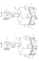
- FIGS. 1B and 1C are diagrams showing an overview of a robot system according to an embodiment of the present invention, in which FIG. 1A is a perspective view of a device main body equipped with a robot arm, and FIGS. 1B and 1C are perspective views of an automatic guided vehicle. It is a diagram. 2A and 2B are perspective views showing the basic operation of the robot system according to the embodiment of the present invention.
- FIG. 3 is a configuration diagram showing an overview of the wireless power supply/charging unit.
- FIG. 4 is a partially cutaway front view showing the positioning mechanism.
- 10 Device body, 10a: Supported surface, 11: Robot arm, 12: Legs, 20: Automatic guided vehicle, 21: Support plate (support surface), 22: Lifting mechanism, 30: Wireless power supply/charging unit, 31: Storage battery, 32: Power transmission circuit, 33: Power transmission coil, 34: Storage battery, 35: Power receiving circuit, 36: Power receiving coil, 37: Power source, 41: Convex portion, 42: Concave portion
- the robot system includes a device main body 10 on which a robot arm 11 is mounted and an automatic guided vehicle 20.
- the robot arm 11 is automatically controlled by a robot control circuit (not shown), and has the function of performing various tasks including product assembly.
- the device main body 10 has a function as a base that supports a robot arm 11, and the robot arm 11 is mounted on the top surface of the device main body 10.
- the apparatus main body 10 shown in the figure has four legs 12, and the lower ends of these legs 12 are arranged on the floor. Note that the arrangement structure of the device main body 10 on the floor is not limited to a structure using a plurality of legs 12.
- the automatic guided vehicle 20 is automatically controlled by a transport control circuit (not shown) and moves by itself.
- This automatic guided vehicle 20 has the function of being able to carry the device main body 10 and move together with it, and also to be able to separate from the device main body 10 and move independently.
- the automatic guided vehicle 20 is equipped with a support plate 21 (support surface) that can be raised and lowered on the upper surface.
- This support board 21 can be raised and lowered by a lifting mechanism 22 built into the automatic guided vehicle 20.
- the bottom surface of the device main body 10 forms a supported surface 10a, and by bringing the support plate 21 into contact with this supported surface 10a, the automatic guided vehicle 20 and the device main body 10 are connected. Then, when the support plate 21 is further raised, the apparatus main body 10 is lifted up.
- the automatic guided vehicle 20 is placed below the device main body 10.
- the support plate 21 when the support plate 21 is raised, it comes into contact with the supported surface 10a (the bottom surface of the device main body 10), and a connection state between the automatic guided vehicle 20 and the device main body 10 is established.
- the device main body 10 is lifted as shown in FIG. 2B. At this time, the legs 12 are lifted off the floor. Thereby, it becomes possible to place the device main body 10 on the automatic guided vehicle 20 and move it together.
- the automatic guided vehicle 20 transports the device main body 10 to a preset work location, lowers the support plate 21, and places the device main body 10 at the work location. With the lowering operation of the support plate 21, the connection state between the automatic guided vehicle 20 and the device main body 10 is released. The device main body 10 equipped with the robot arm 11 executes required work at the work place where it is placed. On the other hand, the automatic guided vehicle 20 can be separated from the device main body 10 and moved independently, thereby making it possible to perform a new transport operation targeting another device main body 10.
- the robot system of this embodiment includes a wireless power supply/charging unit 30 as shown in FIG. It is configured to be rechargeable.
- the wireless power supply/charging unit 30 includes a storage battery 31, a power transmission circuit 32, and a power transmission coil 33 built into the automatic guided vehicle 20, and a storage battery 34, a power receiving circuit 35, and a power receiving coil 36 built into the device main body 10.
- the storage battery 31 built into the automatic guided vehicle 20 can be charged by connecting to an external power source 37.
- This storage battery 31 is used as power for driving the automatic guided vehicle 20, and is also used for power supply to a storage battery 34 built into the device main body 10.
- a storage battery 34 built into the device main body 10 is used as power for driving the robot arm 11.
- a storage battery 31 a power transmission circuit 32, and a power transmission coil 33 are built into the automatic guided vehicle 20, and a power reception circuit 35 and a power reception coil 36 are also built into the device main body 10.
- the built-in positions of the power transmitting coil 33 and the power receiving coil 36 are adjusted so that they are coaxially arranged in a state where the automatic guided vehicle 20 and the device main body 10 are connected.
- the power transmission circuit 32 When the automatic guided vehicle 20 and the device main body 10 are connected, the power transmission circuit 32 is activated, converts the current from the storage battery 31 into alternating current, and energizes the power transmission coil 33. Due to the magnetic flux generated by energizing the power transmitting coil 33, an induced current (alternating current) flows through the power receiving coil 36 based on the principle of electromagnetic induction, so this induced current is converted into direct current by the power receiving circuit 35 and is transferred to the storage battery 34 in the device main body 10. to supply power. In this way, the storage battery 34 within the device main body 10 can be charged. Therefore, there is no need to provide an external power source for charging the storage battery 34 at each work location where the device main body 10 is placed, and it is possible to simplify the equipment.
- the power transmitting coil 33 and the power receiving coil 36 are arranged on the same axis, and there is no misalignment between the central axis of the power transmitting coil 33 and the central axis of the power receiving coil 36.
- the induced current generated in the power receiving coil 36 decreases, and there is a possibility that the storage battery 34 cannot be charged efficiently.
- the robot system includes a positioning mechanism configured by a combination of a convex portion 41 and a concave portion 42, as shown in FIG.
- convex portions 41 are provided at two locations on the upper surface of the support plate 21 of the automatic guided vehicle 20, and recessed portions 42 are provided at two opposing locations on the supported surface 10a of the device main body 10. Then, by raising the support plate 21 and fitting the convex portion 41 into the recess 42, the support plate 21 and the supported surface 10a can be connected in the same positional relationship at all times. In this connected state, the built-in positions are adjusted so that the power transmitting coil 33 and the power receiving coil 36 are arranged coaxially.
- the combination of the convex portion 41 and the concave portion 42 is provided at two opposing positions on the support plate 21 and the supported surface 10a, so that the surface of the support plate 21 and the supported surface 10a is It is possible to eliminate two-dimensional positional deviation within the power transmission coil, and it is possible to accurately arrange the power transmission coil 33 and the power reception coil 36 on the same axis.
- the convex portion 41 has an outer circumferential surface formed in a tapered shape whose diameter decreases toward the tip, and the concave portion 42 has an inner circumferential surface formed in a mortar shape corresponding to the outer circumferential surface of the convex portion 41. .
- the convex portion 41 and the concave portion 42 are formed in such a shape, when the support plate 21 rises and is connected to the supported surface 10a, there is a slight gap between the support plate 21 and the supported surface 10a. Even if there is a misalignment, the convex portion 41 can fit into the opening of the concave portion 42, which is formed wider than its tip, so that the convex portion 41 and the concave portion 42 fit together to eliminate the misalignment. .
- the robot arm 11, device main body 10, and automatic guided vehicle 20 shown in FIGS. 1A to 1C, 2A, and 2B are examples of schematic structures, and their components are limited to the illustrated structures. It's not something you can do.
- the positioning mechanism shown in FIG. 4 has a configuration in which a convex portion 41 is provided on the support plate 21 and a recess portion 42 is provided on the supported surface 10a. It is also possible to have a configuration in which a convex portion 41 is provided. Furthermore, combinations of the convex portions 41 and the concave portions 42 may be provided at three or more opposing positions on the support plate 21 (support surface) and the supported surface 10a.
Landscapes
- Engineering & Computer Science (AREA)
- Mechanical Engineering (AREA)
- Robotics (AREA)
- Life Sciences & Earth Sciences (AREA)
- Sustainable Development (AREA)
- Sustainable Energy (AREA)
- Power Engineering (AREA)
- Transportation (AREA)
- Manipulator (AREA)
Abstract
Description
このように構成することで、無人搬送車と装置本体との間に僅かな位置ずれがあっても凹部と凸部を嵌合させて、正確な位置決めを実現することができる。
このように構成することで、支持面に対して被支持面を二次元的に位置決めすることができ、送電コイルの中心軸に対していっそう正確に受電コイルの中心軸を合わせることが可能となる。
20:無人搬送車、21:支持盤(支持面)、22:昇降機構、
30:ワイヤレス給電・充電ユニット、31:蓄電池、32:送電回路、33:送電コイル、34:蓄電池、35:受電回路、36:受電コイル、37:電源、
41:凸部、42:凹部
図1A~図1C、図2Aおよび図2Bに示すように、本実施形態に係るロボットシステムは、ロボットアーム11を搭載した装置本体10と無人搬送車20とを備えている。
ロボットアーム11は、図示しないロボット制御回路により自動制御され、製品の組み立て作業をはじめとした各種の作業を行うことのできる機能を有している。装置本体10は、ロボットアーム11を支持する基台としての機能を有しており、この装置本体10の上面にロボットアーム11が搭載されている。
図に示す装置本体10は、4本の脚部12を有し、これらの脚部12の下端を床面に配置する構成としてある。なお、装置本体10の床面への配置構造は、複数本の脚部12を用いた構造に限定されるものではない。
さらに、支持盤21を上昇させると、図2Bに示すように、装置本体10が持ち上げられる。このとき、脚部12は床面から浮き上がっている。これにより、無人搬送車20に装置本体10を載せて一体に移動することが可能となる。
ロボットアーム11を搭載した装置本体10は、配置された作業場所において所要の作業を実行する。一方、無人搬送車20は、装置本体10と分離し単独で移動することができ、これにより別の装置本体10を対象として新たに搬送作業を実行することが可能となる。
ワイヤレス給電・充電ユニット30は、無人搬送車20に内蔵した蓄電池31、送電回路32および送電コイル33と、装置本体10に内蔵した蓄電池34、受電回路35および受電コイル36とで構成されている。
ここで、送電コイル33と受電コイル36は、無人搬送車20と装置本体10を接続した状態で、同軸上に配置されるように内蔵位置を調整してある。
したがって、装置本体10を配置する各作業場所に、蓄電池34を充電するための外部電源を設ける必要がなく、設備の簡素化を実現することが可能となる。
そして、支持盤21が上昇して凸部41が凹部42に嵌合することにより、支持盤21と被支持面10aとを常に同じ位置関係で接続することができる。この接続状態で、送電コイル33と受電コイル36は同軸上に配置されるように、内蔵位置が調整されている。
このような形状に凸部41と凹部42を形成することで、支持盤21が上昇して被支持面10aに接続される際に、それら支持盤21と被支持面10aとの間に僅かな位置ずれがあっても、凸部41が、その先端よりも広く形成された凹部42の開口に入り込むことができるので、凸部41と凹部42が嵌合して位置ずれを解消することができる。
例えば、図1A~図1C、図2Aおよび図2Bに示したロボットアーム11、装置本体10および無人搬送車20は、概略構造を例示したもので、それらの構成要素が図示された構造に限定されるものではない。
また、図4に示した位置決め機構は、支持盤21に凸部41を設け、被支持面10aに凹部42を設けた構成としてあったが、支持盤21に凹部42を設け、被支持面10aに凸部41を設けた構成としてもよい。
さらに、凸部41と凹部42の組み合わせは、支持盤21(支持面)と被支持面10aにおける3か所以上の対向位置に設けることもできる。
Claims (4)
- ロボットアームを搭載した装置本体と無人搬送車とを備え、前記無人搬送車に前記装置本体を載せて一体に移動できるとともに、前記装置本体と分離して前記無人搬送車のみで移動することもできる構成のロボットシステムにおいて、
送電コイル、受電コイルおよび蓄電池を含むワイヤレス給電・充電ユニットを備え、前記装置本体が前記受電コイルを内蔵するとともに、前記無人搬送車に前記送電コイルおよび前記蓄電池が内蔵され、
且つ、前記無人搬送車と前記装置本体とを接続する際の位置決め機構を備え、当該位置決め機構により前記送電コイルと前記受電コイルとが同軸上に配置される構成としたことを特徴とするロボットシステム。 - 前記無人搬送車は昇降自在な支持面を上面に有するとともに、前記装置本体は底面に被支持面を形成してあり、
前記無人搬送車を前記装置本体の下方に配置した状態で、前記支持面を上昇させて前記被支持面に接触させることで前記無人搬送車と前記装置本体とが接続され、さらに前記支持面を上昇させて前記装置本体を持ち上げる構成となっており、
前記位置決め機構は、前記支持面と前記被支持面の一方に設けた凸部が他方に設けた凹部に嵌合して、前記送電コイルの中心軸に対して前記受電コイルの中心軸を合わせる構成としたことを特徴とする請求項1に記載のロボットシステム。 - 前記凸部は、外周面が先端に向かって直径が小さくなるテーパ形状に形成してあり、前記凹部は、内周面が前記凸部の外周面に対応したすり鉢状に形成してあることを特徴とする請求項2に記載のロボットシステム。
- 前記凸部と前記凹部の組み合わせを、前記支持面と前記被支持面の少なくとも2か所の対向位置に設けたことを特徴とする請求項2又は3に記載のロボットシステム。
Priority Applications (1)
| Application Number | Priority Date | Filing Date | Title |
|---|---|---|---|
| JP2024520469A JPWO2023219099A1 (ja) | 2022-05-11 | 2023-05-10 |
Applications Claiming Priority (2)
| Application Number | Priority Date | Filing Date | Title |
|---|---|---|---|
| JP2022-078137 | 2022-05-11 | ||
| JP2022078137 | 2022-05-11 |
Publications (1)
| Publication Number | Publication Date |
|---|---|
| WO2023219099A1 true WO2023219099A1 (ja) | 2023-11-16 |
Family
ID=88730226
Family Applications (1)
| Application Number | Title | Priority Date | Filing Date |
|---|---|---|---|
| PCT/JP2023/017538 Ceased WO2023219099A1 (ja) | 2022-05-11 | 2023-05-10 | ロボットシステム |
Country Status (2)
| Country | Link |
|---|---|
| JP (1) | JPWO2023219099A1 (ja) |
| WO (1) | WO2023219099A1 (ja) |
Cited By (1)
| Publication number | Priority date | Publication date | Assignee | Title |
|---|---|---|---|---|
| WO2024247921A1 (ja) * | 2023-05-30 | 2024-12-05 | 川崎重工業株式会社 | ロボット |
Citations (4)
| Publication number | Priority date | Publication date | Assignee | Title |
|---|---|---|---|---|
| JPH06133411A (ja) * | 1992-10-13 | 1994-05-13 | Toshiba Corp | 作業ロボットの給電装置 |
| JP2014117067A (ja) * | 2012-12-10 | 2014-06-26 | Nippon Sharyo Seizo Kaisha Ltd | 無人搬送車の搬送システム |
| JP2021070082A (ja) * | 2019-10-30 | 2021-05-06 | セイコーエプソン株式会社 | ロボットシステムおよびロボットシステムの制御方法 |
| JP2022108046A (ja) * | 2021-01-12 | 2022-07-25 | 株式会社ダイフク | 物品搬送システム |
-
2023
- 2023-05-10 WO PCT/JP2023/017538 patent/WO2023219099A1/ja not_active Ceased
- 2023-05-10 JP JP2024520469A patent/JPWO2023219099A1/ja active Pending
Patent Citations (4)
| Publication number | Priority date | Publication date | Assignee | Title |
|---|---|---|---|---|
| JPH06133411A (ja) * | 1992-10-13 | 1994-05-13 | Toshiba Corp | 作業ロボットの給電装置 |
| JP2014117067A (ja) * | 2012-12-10 | 2014-06-26 | Nippon Sharyo Seizo Kaisha Ltd | 無人搬送車の搬送システム |
| JP2021070082A (ja) * | 2019-10-30 | 2021-05-06 | セイコーエプソン株式会社 | ロボットシステムおよびロボットシステムの制御方法 |
| JP2022108046A (ja) * | 2021-01-12 | 2022-07-25 | 株式会社ダイフク | 物品搬送システム |
Cited By (1)
| Publication number | Priority date | Publication date | Assignee | Title |
|---|---|---|---|---|
| WO2024247921A1 (ja) * | 2023-05-30 | 2024-12-05 | 川崎重工業株式会社 | ロボット |
Also Published As
| Publication number | Publication date |
|---|---|
| JPWO2023219099A1 (ja) | 2023-11-16 |
Similar Documents
| Publication | Publication Date | Title |
|---|---|---|
| CN206812968U (zh) | 自动导引型换电机器人及充换电站 | |
| JP2017132002A (ja) | ロボットアーム付自動搬送車、ロボットシステム、及びロボットアーム付自動搬送車の制御方法 | |
| CN108247598A (zh) | 智能agv升降机器人制孔系统 | |
| US10964571B2 (en) | Conveyance system | |
| US11932096B2 (en) | Overhead traveling vehicle system | |
| WO2023219099A1 (ja) | ロボットシステム | |
| KR20210106550A (ko) | 보관 시스템 | |
| JP6535182B2 (ja) | 台車装置及び作業システム | |
| JP2020082233A (ja) | ロボット用架台、搬送システム及び搬送方法 | |
| JP2015112290A (ja) | アシスト自走台車 | |
| CN110562688A (zh) | 一种定位夹具的快速切换系统 | |
| CN211056032U (zh) | 一种定位夹具的快速切换系统 | |
| CN116635196B (zh) | 机器人 | |
| EP4043144A1 (en) | Pallet for transporting parts | |
| CN118047185A (zh) | 移动式运输装置和包括该移动式运输装置的移动式运输系统 | |
| WO2013035250A1 (ja) | ロール体取扱システム、ロール体供給方法およびロール体搬送装置 | |
| KR102907269B1 (ko) | Agv를 이용하여 조립체를 이송하는 방법 및 시스템 | |
| JP2009172730A (ja) | 車輪位置決め機構 | |
| WO2022249529A1 (ja) | 建設機械システム | |
| CN221828667U (zh) | 电动装置 | |
| EP4717411A1 (en) | Cobot on a mobile platform transported to workstations via an autonomous transport robot | |
| CN112455277B (zh) | 电池更换系统、电池更换方法及自动导引车 | |
| CN110666769A (zh) | 一种自动化表面处理系统 | |
| JP2020024519A (ja) | プログラム、施工ロボット、及び施工システム | |
| CN223734186U (zh) | 大尺寸管道安装装置 |
Legal Events
| Date | Code | Title | Description |
|---|---|---|---|
| 121 | Ep: the epo has been informed by wipo that ep was designated in this application |
Ref document number: 23803574 Country of ref document: EP Kind code of ref document: A1 |
|
| WWE | Wipo information: entry into national phase |
Ref document number: 2024520469 Country of ref document: JP |
|
| NENP | Non-entry into the national phase |
Ref country code: DE |
|
| WWE | Wipo information: entry into national phase |
Ref document number: 11202407694Y Country of ref document: SG |
|
| 122 | Ep: pct application non-entry in european phase |
Ref document number: 23803574 Country of ref document: EP Kind code of ref document: A1 |