WO2023218881A1 - 継電器 - Google Patents
継電器 Download PDFInfo
- Publication number
- WO2023218881A1 WO2023218881A1 PCT/JP2023/015610 JP2023015610W WO2023218881A1 WO 2023218881 A1 WO2023218881 A1 WO 2023218881A1 JP 2023015610 W JP2023015610 W JP 2023015610W WO 2023218881 A1 WO2023218881 A1 WO 2023218881A1
- Authority
- WO
- WIPO (PCT)
- Prior art keywords
- protrusion
- movable contact
- contact
- fixed
- magnet
- Prior art date
- Legal status (The legal status is an assumption and is not a legal conclusion. Google has not performed a legal analysis and makes no representation as to the accuracy of the status listed.)
- Ceased
Links
Images


Classifications
-
- H—ELECTRICITY
- H01—ELECTRIC ELEMENTS
- H01H—ELECTRIC SWITCHES; RELAYS; SELECTORS; EMERGENCY PROTECTIVE DEVICES
- H01H9/00—Details of switching devices, not covered by groups H01H1/00 - H01H7/00
- H01H9/30—Means for extinguishing or preventing arc between current-carrying parts
- H01H9/44—Means for extinguishing or preventing arc between current-carrying parts using blow-out magnet
- H01H9/443—Means for extinguishing or preventing arc between current-carrying parts using blow-out magnet using permanent magnets
-
- H—ELECTRICITY
- H01—ELECTRIC ELEMENTS
- H01H—ELECTRIC SWITCHES; RELAYS; SELECTORS; EMERGENCY PROTECTIVE DEVICES
- H01H1/00—Contacts
- H01H1/06—Contacts characterised by the shape or structure of the contact-making surface, e.g. grooved
-
- H—ELECTRICITY
- H01—ELECTRIC ELEMENTS
- H01H—ELECTRIC SWITCHES; RELAYS; SELECTORS; EMERGENCY PROTECTIVE DEVICES
- H01H50/00—Details of electromagnetic relays
-
- H—ELECTRICITY
- H01—ELECTRIC ELEMENTS
- H01H—ELECTRIC SWITCHES; RELAYS; SELECTORS; EMERGENCY PROTECTIVE DEVICES
- H01H50/00—Details of electromagnetic relays
- H01H50/14—Terminal arrangements
-
- H—ELECTRICITY
- H01—ELECTRIC ELEMENTS
- H01H—ELECTRIC SWITCHES; RELAYS; SELECTORS; EMERGENCY PROTECTIVE DEVICES
- H01H50/00—Details of electromagnetic relays
- H01H50/16—Magnetic circuit arrangements
- H01H50/36—Stationary parts of magnetic circuit, e.g. yoke
- H01H50/38—Part of main magnetic circuit shaped to suppress arcing between the contacts of the relay
-
- H—ELECTRICITY
- H01—ELECTRIC ELEMENTS
- H01H—ELECTRIC SWITCHES; RELAYS; SELECTORS; EMERGENCY PROTECTIVE DEVICES
- H01H50/00—Details of electromagnetic relays
- H01H50/54—Contact arrangements
-
- H—ELECTRICITY
- H01—ELECTRIC ELEMENTS
- H01H—ELECTRIC SWITCHES; RELAYS; SELECTORS; EMERGENCY PROTECTIVE DEVICES
- H01H50/00—Details of electromagnetic relays
- H01H50/54—Contact arrangements
- H01H50/546—Contact arrangements for contactors having bridging contacts
-
- H—ELECTRICITY
- H01—ELECTRIC ELEMENTS
- H01H—ELECTRIC SWITCHES; RELAYS; SELECTORS; EMERGENCY PROTECTIVE DEVICES
- H01H9/00—Details of switching devices, not covered by groups H01H1/00 - H01H7/00
- H01H9/30—Means for extinguishing or preventing arc between current-carrying parts
- H01H9/44—Means for extinguishing or preventing arc between current-carrying parts using blow-out magnet
Definitions
- the present invention generally relates to electrical relays.
- the relay described in Patent Document 1 includes a contact portion made up of two movable contacts and two fixed contacts.
- the movable contact and the fixed contact touch or separate from each other.
- the arc generated between the movable contact and the fixed contact may directly extend from the left and right end surfaces of the movable contact in a direction perpendicular to the left and right end surfaces.
- the direction in which the arc is extended is parallel to the direction of the magnetic flux of the magnet.
- the present invention provides a first fixed terminal including a first fixed contact, a second fixed terminal located to the left of the first fixed terminal and including a second fixed contact, and a second fixed terminal that contacts or separates from the first fixed contact. It has a movable contact including a first protrusion, and a first magnet facing the movable contact.
- the first magnet is provided to the right of the right end of the movable contact. Further, the first protrusion overlaps the first fixed contact when viewed from above. The right end of the first fixed contact is located to the left of the right end of the movable contact and to the right of the right end of the first protrusion.
- the arc extinguishing ability of the relay can be improved.
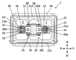
- FIG. 1 is a plan view of a relay in an embodiment of the present invention.
- FIG. 2 is a side view of the relay in the embodiment of the invention.
- FIG. 3 is a sectional view taken along line AA in FIG. 1 of the relay according to the embodiment of the present invention.
- FIG. 4 is a sectional view taken along line AA in FIG. 1 of the relay according to the embodiment of the present invention.
- FIG. 5 is a perspective view of a movable contact of a relay in an embodiment of the present invention.
- FIG. 6 is a sectional view taken along line BB in FIG. 2 of the relay according to the embodiment of the present invention.
- the relay 1 As shown in FIGS. 1 to 4, the relay 1 according to the embodiment of the present invention includes a first fixed terminal 11, a second fixed terminal 15, a casing 21, a movable contact 30, and a first magnet. 41, a second magnet 42, and a movable shaft 51.
- the first fixed terminal 11 is made of a conductive material such as copper, has a substantially cylindrical shape, and is fixed to the upper surface of the casing 21.
- the upper end of the first fixed terminal 11 is exposed outside the housing 21, and the lower end of the first fixed terminal 11 is inserted into the housing 21.
- the lower end surface of the first fixed terminal 11 includes a first fixed contact 12 that comes into contact with or separates from a first protrusion 31 of a movable contact 30, which will be described later.
- FIG. 6 is a sectional view taken along line BB in FIG. 2 of the relay 1 according to the embodiment of the present invention.
- the projections of the first fixed contact 12 and the second fixed contact 16 are shown as hatched circular areas with dotted boundaries.
- the first fixed contact 12 overlaps the movable contact 30 in plan view.
- planar view means viewing from above.
- the outer edge of the first fixed contact 12 is located inside the outer edge of the movable contact 30 in plan view.
- the first fixed contact 12 overlaps the movable contact 30 in plan view means that the first fixed contact 12 and the movable contact 30 are each projected onto a horizontal plane perpendicular to the plan view direction, and the projections of both are This means that they overlap, at least in part.
- a and B overlap in the following description means that A and B are each projected onto a plane perpendicular to the observation direction, and their projections overlap at least in part.
- the second fixed terminal 15 is arranged on the left side of the first fixed terminal 11.
- the first fixed terminal 11 and the second fixed terminal 15 are arranged side by side in the left-right direction.
- the second fixed terminal 15 is made of a conductive material such as copper and has a substantially cylindrical shape.
- the second fixed terminal 15 is fixed to the upper wall of the casing 21, with its upper end exposed outside the casing 21 and its lower end inserted into the casing 21.
- the lower end surface of the second fixed terminal 15 includes a second fixed contact 16 that comes into contact with or separates from a second protrusion 32 and/or a third protrusion 33 of a movable contactor 30, which will be described later.
- the second fixed contact 16 overlaps the movable contact 30 when looking down, and the outer edge of the second fixed contact 16 is located inside the outer edge of the movable contact 30 when looking down. are doing.
- the casing 21 is made of a heat-resistant material such as ceramic, and is a rectangular box with a downward opening, and includes an upper wall and a peripheral wall.
- the movable contact 30 is housed in a housing 21, and the housing 21 covers the movable contact 30.
- the first fixed terminal 11 and the second fixed terminal 15 are inserted into the housing 21 .
- the housing 21 is located between the first magnet 41 and the second magnet 42.
- a lower opening of the housing 21 is closed by a bottom plate 22, and a through hole 221 through which the movable shaft 51 passes is provided in the center of the bottom plate 22.
- a connecting flange 23 is provided between the housing 21 and the bottom plate 22 in order to improve the sealing performance between the housing 21 and the bottom plate 22.
- the movable contact 30 is formed of a conductive material such as copper.
- the length of the movable contact 30 is greater than the width of the movable contact 30. That is, the distance from the right end 30a to the left end 30b of the movable contact 30 is greater than the distance from one side 30c of the movable contact 30 to the other side 30d. Furthermore, the width of the movable contact 30 is greater than the thickness of the movable contact 30.
- a first protrusion 31 that protrudes upward is provided on the upper surface of the movable contact 30.
- the first protrusion 31 has a substantially trapezoidal shape in plan view that is symmetrical with respect to the center line of the movable contactor 30 in the left-right direction, and the width of the first protrusion 31 in the front-rear direction increases from left to right.
- the first protrusion 31 contacts or separates from the first fixed contact 12 . That is, the first protrusion 31 has a first movable contact. In other words, the movable contact 30 has the first protrusion 31 that comes into contact with or separates from the first fixed contact 12.
- the movable contactor 30 includes a first base portion 34 located on the right side of the first protrusion 31.
- the first protrusion 31 projects upward from the first base 34 . Therefore, the distance between the first protrusion 31 and the first fixed terminal 11 is smaller than the distance between the first base 34 and the first fixed terminal 11.
- the upper surface of the first base 34 is an inclined surface that slopes downward as it approaches the right end 30a of the movable contact 30.
- the distance between the first base 34 and the first fixed terminal 11 becomes larger toward the right end 30a of the movable contact 30. Therefore, the arc is gradually stretched as it moves on the first base 34 toward the right end 30a.
- first protrusion 31 and the first base 34 are connected by a side surface of the first protrusion 31 that is formed of a smooth curved surface. Thereby, the arc generated by the first protrusion 31 can easily move toward the first base 34.
- the movable contactor 30 has a second protrusion 32 and a third protrusion 33 arranged in parallel with the second protrusion 32.
- Each of the second protrusion 32 and the third protrusion 33 overlaps with the second fixed contact 16 in plan view.
- the second protrusion 32 and the third protrusion 33 are provided on the upper surface of the movable contactor 30 and are lined up in the front-rear direction. Current flows through the movable contactor 30 in the left-right direction. Therefore, the front-rear direction is a direction perpendicular to the direction in which current flows through the movable contact 30. That is, the second protrusion 32 and the third protrusion 33 are arranged in a direction perpendicular to the direction in which current flows through the movable contact 30.
- the second protrusion 32 and the third protrusion 33 have a substantially right trapezoidal shape in plan view, and their oblique sides face each other in the front-rear direction. As a result, the shortest distance between the second protrusion 32 and the third protrusion 33 (that is, the distance in the front-back direction) becomes larger as the left end of the movable contact 30 approaches.
- the second protrusion 32 and the third protrusion 33 have a second movable contact that comes into contact with the second fixed contact 16 .
- the movable contact 30 By providing the first protrusion 31 on the movable contact 30 as a first movable contact, and providing the second protrusion 32 and the third protrusion 33 as second movable contacts, when the relay 1 is closed, the movable contact 30 , contacts the first fixed terminal 11 and the second fixed terminal 15 at three points. With this configuration, when the movable contact 30 is in contact with the first fixed terminal 11 and the second fixed terminal 15, the movable contact 30 is prevented from shaking.
- the second fixed contact 16 contacts both the second protrusion 32 and the third protrusion 33; for example, the second fixed contact 16 may contact either the second protrusion 32 or the third protrusion 33. May contact.
- the movable contactor 30 has a second base portion 35 located on the left side of the second protrusion 32.
- the second protrusion 32 projects upward from the second base 35.
- the distance between the second protrusion 32 and the second fixed terminal 15 is smaller than the distance between the second base 35 and the second fixed terminal 15.
- the upper surface of the second base portion 35 is an inclined surface that slopes downward as it approaches the left end portion 30b of the movable contactor 30. Therefore, the distance between the second base 35 and the second fixed terminal 15 becomes larger toward the left end 30b of the movable contact 30. Therefore, the arc is gradually stretched as it moves on the second base 35 toward the left end 30b.
- the second protrusion 32 and the second base 35 are connected by a side surface of the second protrusion 32 that is formed of a smooth curved surface. Thereby, the arc generated at the second protrusion 32 can easily move from the second protrusion 32 toward the second base 35.
- the third protrusion 33 and the second base 35 are connected by a side surface of the third protrusion 33 that is formed of a smooth curved surface. With this configuration, the arc generated at the third protrusion 33 can easily move from the third protrusion 33 toward the second base 35.
- the movable contact 30 is held at the upper end of the movable shaft 51 by a holder 52, and moves up and down as the movable shaft 51 moves up and down, and moves between the open position and the closed position. You can move with.
- the movable contactor 30 is located in an open position, and this state may be referred to as an "open state.”
- the movable contactor 30 is located in a closed position, and this state may be referred to as a "closed state”.
- the movable shaft 51 moves upward, moves the movable contact 30 upward, and the upper surface of the first protrusion 31 contacts the first fixed contact 12, and The upper surfaces of the second protrusion 32 and the third protrusion 33 contact the second fixed contact 16.
- the movable contactor 30 By moving the movable contactor 30 upward, conduction is established between the first fixed terminal 11 and the second fixed terminal 15 (see FIG. 4).
- FIG. 4 shows the state in which the relay 1 is switched to the closed position.
- the movable shaft 51 moves downward by the action of the recovery spring, and the movable contact 30 moves downward.
- the first protrusion 31 is separated from the first fixed contact 12, and the second protrusion 32 and the third protrusion 33 are separated from the second fixed contact 16.
- the relay 1 is switched to the cutoff position shown in FIG.
- a first magnet 41 is provided on the right side of the casing 21, and a second magnet 42 is provided on the left side of the casing 21.
- the first magnet 41 and the second magnet 42 are provided so as to face each other in the front-rear direction.
- the first magnet 41 and the second magnet 42 are held by a first holder 45 and a second holder 46, respectively, which are approximately U-shaped.
- the first magnet 41 is held on the outer surface of the right side wall 21a of the housing 21, and the second magnet 42 is held on the outer surface of the left side wall 21b of the housing 21.
- the first magnet 41 and the second magnet 42 are arranged so that the same poles face each other.
- the north poles are arranged to face each other
- the left side of the first magnet 41 is the north pole
- the right side is the south pole
- the right side of the second magnet 42 is the north pole
- the left side is the south pole.
- the left side is the south pole.
- the magnets have the same polarity facing each other
- the first magnet 41 and the second magnet 42 may have different polarities facing each other.
- the first magnet 41 is, for example, a permanent magnet such as a ferrite magnet or a neodymium magnet.
- the first magnet 41 is provided on the right side of the right end of the movable contact 30 and faces the movable contact 30 . Further, the first magnet 41 is arranged so as to overlap the movable contact 30 when viewed from the right side, and the width of the first magnet 41 in the front-rear direction is larger than the width of the movable contact 30 in the front-rear direction. is preferred.
- the height of the first magnet 41 in the vertical direction is preferably larger than the distance between the first fixed contact 12 and the first protrusion 31 when the movable contact 30 is in the open position.
- the first magnet 41 generates a magnetic flux from right to left in the space between the first fixed contact 12 and the first protrusion 31.
- the second magnet 42 is, for example, a permanent magnet such as a ferrite magnet or a neodymium magnet.
- the second magnet 42 is provided on the left side of the left end of the movable contact 30 and faces the movable contact 30 . Further, the second magnet 42 is arranged so as to overlap the movable contact 30 when viewed from the left side, and the width of the second magnet 42 in the front-rear direction is larger than the width of the movable contact 30 in the front-rear direction. is preferred.
- the height of the second magnet 42 in the vertical direction is determined by the distance between the second fixed contact 16 and the second protrusion 32 when the movable contact 30 is in the open position, and the distance between the second fixed contact 16 and the third protrusion 33. It is preferable that the distance is larger than the distance between the two.
- the second magnet 42 generates magnetic flux from left to right in the space between the second fixed contact 16 and the second protrusion 32 and in the space between the second fixed contact 16 and the third protrusion 33. do.
- the Lorentz force acting on the generated arc can be considered in the same way. That is, the forward Lorentz force F1 acts on the arc generated between the first fixed contact 12 and the first protrusion 31.
- a forward Lorentz force F2 is generated for the arc generated between the second fixed contact 16 and the second protrusion 32 or the third protrusion 33.
- the distance in the left-right direction between the inner surface of the right side wall 21a of the casing 21 and the right end 30a of the movable contact 30 is the inner surface of the front side wall 21c of the casing 21. and the side surface 30c of the movable contact 30, and smaller than the distance in the front-rear direction between the inner surface of the rear wall 21d of the housing 21 and the side surface 30d of the movable contact 30.
- the shortest distance between the inner surface of the casing 21 and the right end 30a of the movable contact 30 is the shortest distance between the inner surface of the casing 21 and the side surface 30c, and the shortest distance between the inner surface of the casing 21 and the side surface 30d. is smaller than the shortest distance.
- the space between the inner surface of the casing 21 and the right end 30a of the movable contact 30 is relatively small, and the space between the inner surface of the casing 21 and the side surfaces 30c and 30d of the movable contact 30 is relatively small. It's a big target.
- the distance in the left-right direction between the inner surface of the left side wall 21b of the casing 21 and the left end 30b of the movable contact 30 is the same as the distance between the inner surface of the front wall 21c of the casing 21 and the movable contact , and smaller than the distance in the front-back direction between the inner surface of the rear wall 21d of the housing 21 and the side surface 30d of the movable contact 30.
- the shortest distance between the inner surface of the casing 21 and the left end 30b of the movable contact 30 is the shortest distance between the inner surface of the casing 21 and the side surface 30c, and the shortest distance between the inner surface of the casing 21 and the side surface 30d. less than the shortest distance.
- first protrusions 24 and a pair of second protrusions 25 are provided on the inner surfaces of the front wall 21c and the rear wall 21d of the housing 21, facing each other.
- the first protrusion 24 is located on the right side of the second protrusion 25, and the protrusion height of the first protrusion 24 in the front-rear direction is smaller than the protrusion height of the second protrusion 25 in the front-rear direction.
- the first convex portion 24 can prevent the arc generated on the first fixed contact 12 side from propagating to the second fixed contact 16 side
- the second convex portion 25 can prevent the arc generated on the second fixed contact 16 side from propagating. Propagation to the first fixed contact 12 side can be prevented.
- the second convex portion 25 can also restrict the rotation of the movable contact 30 by coming into contact with the movable contact 30 or the holder 52 .
- the first protrusion 31 overlaps with the first fixed contact 12, and the first protrusion 31 is completely covered by the first fixed contact 12. Further, the right end of the first fixed contact 12 is located to the left of the right end of the movable contact 30 and to the right of the right end of the first projection 31. Thereby, a distance over which the arc moves can be ensured between the right end of the first protrusion 31 and the right end (right end portion 30a) of the movable contact 30.
- the arc generated between the right end (right end 30b) of the first protrusion 31 and the right end of the movable contact 30 is set to move toward the right end 30a of the movable contact 30. arc can be suppressed.
- the arc extends rightward from the right end 30a of the movable contactor 30, the direction in which the arc extends and the direction of the magnetic flux of the first magnet 41 are approximately parallel, and a Lorentz force is applied to the arc. It becomes difficult to work and it becomes difficult to extinguish the arc. Further, if the space between the inner surface of the housing 21 and the right end portion 30a of the movable contact 30 is relatively small, it becomes difficult to further extend the arc and extinguish it.
- the generated arc moves toward the side surface 30d of the movable contact 30 and extends rearward from the side surface 30d of the movable contact 30. Therefore, a relatively large Lorentz force tends to act on the arc, making it easier to extinguish the arc.
- the second protrusion 32 and the third protrusion 33 overlap with the second fixed contact 16. Further, the left end of the second fixed contact 16 is located to the right of the left end of the movable contact 30 and to the left of the left ends of the second protrusion 32 and the third protrusion 33. As a result, between the left end of the second protrusion 32 and the left end (left end part 30b) of the movable contact 30, and between the left end of the third protrusion 33 and the left end (left end part 30b) of the movable contact 30, The distance traveled by the arc can be secured.
- a current flows from the first fixed terminal 11 to the second fixed terminal 15 when the movable contact 30 of the relay 1 is in the closed state.
- the movable contact 30 moves from the closed position to the open position, there is a gap between the contact area between the second fixed contact 16 and the second protrusion 32 or between the contact area between the second fixed contact 16 and the third protrusion 33.
- An arc occurs between. The arc moves along the upper surface of the movable contact 30 starting from the second protrusion 32 or the third protrusion 33.
- the direction in which the arc extends and the direction of the magnetic flux of the second magnet 42 are approximately parallel, and the Lorentz force is applied to the arc. becomes difficult to work, making it difficult to extinguish the arc. Furthermore, if the space between the inner surface of the housing 21 and the left end portion 30b of the movable contact 30 is relatively small, it becomes difficult to further extend the arc and extinguish the arc.
- the generated arc moves toward the side surface 30d of the movable contact 30 and extends rearward from the side surface 30d of the movable contact 30. Therefore, a relatively large Lorentz force is likely to be generated in the arc, making it easier to extinguish the arc.
- the upper surface of the first base portion 34 is formed as an inclined surface. Therefore, even if the movable contact 30 moves from the closed position to the open position and tilts in the left-right direction, the distance between the first protrusion 31 and the first fixed terminal 11 remains the same as that between the first base 34 and the first fixed terminal. This distance is smaller than the distance to the terminal 11.
- the upper surface of the second base portion 35 is formed as an inclined surface. Therefore, even if the movable contact 30 moves from the closed position to the open position and tilts in the left-right direction, the distance between the second protrusion 32 and the second fixed terminal 15 and the distance between the third protrusion 33 and the second fixed terminal 15 is smaller than the distance between the second base 35 and the second fixed terminal 15.
- the arc can more easily move along the upper surface of the movable contactor 30 starting from the first protrusion 31, the second protrusion 32, and the third protrusion 33, and the moving distance of the arc can be further secured.
- the movable contact 30 is provided with the second protrusion 32 and the third protrusion 33, but the second protrusion 32 and the third protrusion 33 are It may also be used as a protrusion.
- the movable contactor 30 is provided with the first protrusion 31, but another protrusion arranged in parallel with the first protrusion 31 may be provided to provide the second protrusion 32. It is also possible to have two or more protrusions such as the third protrusion 33 and the third protrusion 33.
- each of the first base 34 and the second base 35 is not an inclined surface that slopes downward, but is, for example, a flat surface that is aligned with the upper surface of other parts of the movable contactor 30. It may be a surface.
- the above-described relay 1 can improve arc extinguishing ability.
Landscapes
- Physics & Mathematics (AREA)
- Electromagnetism (AREA)
- Arc-Extinguishing Devices That Are Switches (AREA)
Priority Applications (2)
| Application Number | Priority Date | Filing Date | Title |
|---|---|---|---|
| US18/859,341 US20250266218A1 (en) | 2022-05-12 | 2023-04-19 | Relay |
| JP2024520332A JPWO2023218881A1 (https=) | 2022-05-12 | 2023-04-19 |
Applications Claiming Priority (2)
| Application Number | Priority Date | Filing Date | Title |
|---|---|---|---|
| CN202210518738.1 | 2022-05-12 | ||
| CN202210518738.1A CN117095988A (zh) | 2022-05-12 | 2022-05-12 | 继电器 |
Publications (1)
| Publication Number | Publication Date |
|---|---|
| WO2023218881A1 true WO2023218881A1 (ja) | 2023-11-16 |
Family
ID=88730273
Family Applications (1)
| Application Number | Title | Priority Date | Filing Date |
|---|---|---|---|
| PCT/JP2023/015610 Ceased WO2023218881A1 (ja) | 2022-05-12 | 2023-04-19 | 継電器 |
Country Status (4)
| Country | Link |
|---|---|
| US (1) | US20250266218A1 (https=) |
| JP (1) | JPWO2023218881A1 (https=) |
| CN (1) | CN117095988A (https=) |
| WO (1) | WO2023218881A1 (https=) |
Citations (6)
| Publication number | Priority date | Publication date | Assignee | Title |
|---|---|---|---|---|
| JP2008226547A (ja) * | 2007-03-09 | 2008-09-25 | Denso Corp | 電磁継電器 |
| WO2011115049A1 (ja) * | 2010-03-15 | 2011-09-22 | オムロン株式会社 | 接点開閉装置 |
| JP2013175436A (ja) * | 2012-01-25 | 2013-09-05 | Ngk Spark Plug Co Ltd | 継電器 |
| JP2013246873A (ja) * | 2012-05-23 | 2013-12-09 | Panasonic Corp | 接点装置 |
| WO2018131639A1 (ja) * | 2017-01-11 | 2018-07-19 | パナソニックIpマネジメント株式会社 | 接点装置、電磁継電器、電気機器 |
| KR102207338B1 (ko) * | 2020-07-07 | 2021-01-25 | 주식회사 와이엠텍 | 아크 소호 능력을 갖는 직류 양방향 접점 장치 |
-
2022
- 2022-05-12 CN CN202210518738.1A patent/CN117095988A/zh active Pending
-
2023
- 2023-04-19 JP JP2024520332A patent/JPWO2023218881A1/ja active Pending
- 2023-04-19 WO PCT/JP2023/015610 patent/WO2023218881A1/ja not_active Ceased
- 2023-04-19 US US18/859,341 patent/US20250266218A1/en active Pending
Patent Citations (6)
| Publication number | Priority date | Publication date | Assignee | Title |
|---|---|---|---|---|
| JP2008226547A (ja) * | 2007-03-09 | 2008-09-25 | Denso Corp | 電磁継電器 |
| WO2011115049A1 (ja) * | 2010-03-15 | 2011-09-22 | オムロン株式会社 | 接点開閉装置 |
| JP2013175436A (ja) * | 2012-01-25 | 2013-09-05 | Ngk Spark Plug Co Ltd | 継電器 |
| JP2013246873A (ja) * | 2012-05-23 | 2013-12-09 | Panasonic Corp | 接点装置 |
| WO2018131639A1 (ja) * | 2017-01-11 | 2018-07-19 | パナソニックIpマネジメント株式会社 | 接点装置、電磁継電器、電気機器 |
| KR102207338B1 (ko) * | 2020-07-07 | 2021-01-25 | 주식회사 와이엠텍 | 아크 소호 능력을 갖는 직류 양방향 접점 장치 |
Also Published As
| Publication number | Publication date |
|---|---|
| CN117095988A (zh) | 2023-11-21 |
| US20250266218A1 (en) | 2025-08-21 |
| JPWO2023218881A1 (https=) | 2023-11-16 |
Similar Documents
| Publication | Publication Date | Title |
|---|---|---|
| JP6907801B2 (ja) | 電磁継電器 | |
| KR101993108B1 (ko) | 전자 계전기 및 코일 단자 | |
| JP5986419B2 (ja) | 接点装置及びこれを使用した電磁開閉器 | |
| JP5727862B2 (ja) | 電磁接触器 | |
| JP5778989B2 (ja) | 電磁接触器 | |
| JP5767508B2 (ja) | 電磁接触器 | |
| JP6648683B2 (ja) | 電磁継電器 | |
| CN103155084A (zh) | 电磁接触器 | |
| JP2016072020A (ja) | 接点装置 | |
| WO2022123873A1 (ja) | 接点装置及び電磁継電器 | |
| JP2016072021A (ja) | 接点装置 | |
| JP2022141412A (ja) | 電磁継電器 | |
| CN113168997B (zh) | 电磁继电器 | |
| CN105097362A (zh) | 触点装置 | |
| JP7056549B2 (ja) | 電磁継電器 | |
| WO2023218881A1 (ja) | 継電器 | |
| WO2022230516A1 (ja) | 接点装置及び電磁継電器 | |
| JP2019117810A (ja) | 電磁継電器 | |
| CN113168999B (zh) | 电磁继电器 | |
| JP2019046620A (ja) | 電磁継電器 | |
| JP2021057319A (ja) | 接点機構及びこれを使用した電磁接触器 | |
| JP2022141411A (ja) | 電磁継電器 | |
| JP2024169877A (ja) | 接点機構、及び電磁継電器 | |
| JP2023008418A (ja) | 電磁継電器 |
Legal Events
| Date | Code | Title | Description |
|---|---|---|---|
| 121 | Ep: the epo has been informed by wipo that ep was designated in this application |
Ref document number: 23803363 Country of ref document: EP Kind code of ref document: A1 |
|
| WWE | Wipo information: entry into national phase |
Ref document number: 18859341 Country of ref document: US |
|
| WWE | Wipo information: entry into national phase |
Ref document number: 2024520332 Country of ref document: JP |
|
| NENP | Non-entry into the national phase |
Ref country code: DE |
|
| 122 | Ep: pct application non-entry in european phase |
Ref document number: 23803363 Country of ref document: EP Kind code of ref document: A1 |
|
| WWP | Wipo information: published in national office |
Ref document number: 18859341 Country of ref document: US |