WO2023218844A1 - 画像処理装置及び画像処理方法 - Google Patents
画像処理装置及び画像処理方法 Download PDFInfo
- Publication number
- WO2023218844A1 WO2023218844A1 PCT/JP2023/014886 JP2023014886W WO2023218844A1 WO 2023218844 A1 WO2023218844 A1 WO 2023218844A1 JP 2023014886 W JP2023014886 W JP 2023014886W WO 2023218844 A1 WO2023218844 A1 WO 2023218844A1
- Authority
- WO
- WIPO (PCT)
- Prior art keywords
- search
- image
- parallax
- search range
- disparity
- Prior art date
- Legal status (The legal status is an assumption and is not a legal conclusion. Google has not performed a legal analysis and makes no representation as to the accuracy of the status listed.)
- Ceased
Links
Images


Classifications
-
- G—PHYSICS
- G06—COMPUTING OR CALCULATING; COUNTING
- G06T—IMAGE DATA PROCESSING OR GENERATION, IN GENERAL
- G06T7/00—Image analysis
- G06T7/50—Depth or shape recovery
- G06T7/55—Depth or shape recovery from multiple images
- G06T7/593—Depth or shape recovery from multiple images from stereo images
-
- G—PHYSICS
- G06—COMPUTING OR CALCULATING; COUNTING
- G06T—IMAGE DATA PROCESSING OR GENERATION, IN GENERAL
- G06T2207/00—Indexing scheme for image analysis or image enhancement
- G06T2207/10—Image acquisition modality
- G06T2207/10004—Still image; Photographic image
- G06T2207/10012—Stereo images
Definitions
- the present invention relates to an image processing device and an image processing method that monitor objects existing around a vehicle using images taken with a photographing device.
- a position measuring device uses the principle of triangulation to measure the distance to an object within the field of view of the camera based on a stereo image taken by a stereo camera having a pair of cameras.
- the principle of triangulation is to calculate the distance from the camera to the object using the positional shift (parallax) between the images of the same object photographed by the left and right cameras.
- the parallax is derived by specifying where the image of the object on one image exists on the other image.
- Patent Document 1 in order to calculate a higher resolution (lower) parallax, only the area around the lower resolution (upper) parallax calculated in advance is searched, thereby reducing the amount of calculation and calculation time.
- searching for disparity for example, it is assumed that the degree of dissimilarity between the intra-image areas of the left and right images is minimum at the edge of the disparity search range, and that true disparity exists outside the search range. For some reason, the reliability of the calculated parallax may be deemed to be low and the parallax may be invalidated.
- hierarchical search if a lower resolution parallax is deemed invalid, higher resolution parallaxes corresponding to this lower resolution parallax cannot be searched and are all invalidated. Therefore, there is a problem that a large amount of invalid parallax may occur in the final high-resolution parallax image.
- an image processing device is an image processing device including a parallax calculation unit that calculates parallax by comparing two images captured by two cameras.
- the parallax calculation unit selects an image block having the highest degree of similarity to a first image block that is an image area of a first size and is included in one of the two images, and selects an image block that has the highest degree of similarity from the first image block that is an image area of a first size and is included in one of the two images.
- a first-layer stereo matching process that determines a first parallax in units of image regions of a first size by specifying from a first search range determined based on a first predetermined search width;
- An image block that is an image area of a second size smaller than the first size and has the highest degree of similarity to a second image block included in one of the two images is selected from among the other image of the two images.
- a second layer that calculates a second parallax in units of image regions of a second size by specifying from a second search range determined based on the first parallax and a predetermined second search width. Performs stereo matching processing.
- the parallax calculation unit calculates the first search width or The second search range is expanded and the search is performed.
- the search range is information about the start and end points of the search that determines the search width.
- FIG. 2 is a diagram showing an example of a hardware configuration of a control system in a vehicle.
- FIG. 3 is a diagram showing a comparison of the surroundings of a vehicle, a coarse distance image, and a detailed distance image.
- 1 is a block diagram showing an example of a functional configuration of an arithmetic device according to a first embodiment of the present invention.
- FIG. 3 is a diagram illustrating the concept of disparity determination by a disparity search unit included in the disparity calculation unit in the first embodiment of the present invention.
- FIG. 7 is a diagram illustrating an example of local re-search determination and an example of a search range extension direction during re-search according to the first embodiment of the present invention.
- FIG. 12 is a flowchart illustrating an example of a procedure for a local search process for the Nth layer of hierarchical search according to the first embodiment of the present invention.
- FIG. 7 is a block diagram showing an example of a functional configuration of a parallax calculation unit in an arithmetic device according to a second embodiment of the present invention.
- 12 is a flowchart illustrating an example of a procedure of local search processing for the Nth layer of hierarchical search according to the second embodiment of the present invention.
- FIG. 7 is a diagram showing an example of the magnitude of dissimilarity within a local search range in the second embodiment of the present invention.
- 12 is a flowchart illustrating a procedure example of local search processing for the Nth layer of hierarchical search according to the third embodiment of the present invention.
- FIG. 1 is a diagram showing an example of the hardware configuration of a control system in a vehicle.
- the vehicle 10 shown in FIG. 1 includes a calculation device 1, a left camera 2, a right camera 3, and a vehicle control device 4.
- the computing device 1 and the vehicle control device 4 are electronic control units (ECUs).
- the left camera 2 and the right camera 3 photograph the surroundings of the vehicle 10 and output captured images to the arithmetic device 1 .
- the left camera 2 and the right camera 3 are arranged side by side in the horizontal direction.
- the image taken by the left camera 2 will be referred to as a first camera image 21, and the image taken by the right camera 3 will be referred to as a second camera image 31.
- the left camera 2 may be called a "first camera” and the right camera 3 may be called a "second camera”.
- both the first camera image 21 (left image) and the second camera image 31 (right image) are spread out in the vertical and horizontal directions. This is an image obtained by photographing a certain three-dimensional space.
- the term "horizontal” or “vertical” as used herein does not have a strict meaning, but only means that the horizontal direction of the first camera image 21 and the second camera image 31 corresponds to the horizontal direction rather than the vertical direction.
- the left camera 2 and the right camera 3 may be tilted at a maximum of about 30 degrees around the optical axis.
- the arithmetic device 1 includes a CPU 11 that is a central processing unit, a ROM 12 that is a read-only storage device, a RAM 13 that is a readable/writable storage device, and an interface 14 that receives the first camera image 21 and the second camera image 31.
- a CPU 11 loads a computer program stored in the ROM 12 into the RAM 13 and executes it, a plurality of functions of the arithmetic device 1, which will be described later, are realized.
- the computer program may be stored in a non-volatile storage (not shown).
- the ROM 12 and non-volatile storage are used as an example of a computer-readable non-transitory recording medium that stores the program.
- the arithmetic unit 1 uses an FPGA (Field Programmable Gate Array), which is a rewritable logic circuit, and an ASIC (Application Specific Integrated Circuit), which is an integrated circuit for a specific purpose. Some or all of these functions may be implemented. Furthermore, instead of the combination of the CPU 11, ROM 12, and RAM 13, the arithmetic device 1 may be realized by a combination of different configurations, for example, a combination of the CPU 11, ROM 12, RAM 13, and FPGA.
- FPGA Field Programmable Gate Array
- ASIC Application Specific Integrated Circuit
- the interface 14 receives the first camera image 21 (left image) and the second camera image 31 (right image) and provides them to the CPU 11. However, since only a small amount of information can be stored in the register provided in the CPU 11, the interface 14 stores the received first camera image 21 and second camera image 31 in the RAM 13 so that the CPU 11 can freely refer to the information. do.
- the calculation device 1 uses the input first camera image 21 (left image) and second camera image 31 (right image) to create a distance image 41 (including distance information to objects around the vehicle 10 based on parallax). (see FIG. 2) and outputs it to the vehicle control device 4.
- the process by which the arithmetic device 1 creates the distance image 41 will be described in detail later with reference to FIG. 2 and subsequent figures.
- the distance image 41 represents distances in a two-dimensional plane using color shading and color saturation. However, in the present embodiment, each pixel of the distance image 41 stores an integer value between "0" and "255" representing shading. Among these, "0" is a special numerical value indicating that calculation of the distance was impossible.
- the range shown in the distance image 41 is approximately the same as the first camera image 21 (left image) and the second camera image 31 (right image). However, the range shown in the distance image 41 may be narrower than the range shown in the first camera image 21 and the second camera image 31.
- the number of pixels of the distance image 41 may be approximately the same as the first camera image 21 and the second camera image 31, or may be smaller than the number of pixels of the first camera image 21 and the second camera image 31.
- the three-dimensional spaces recorded in the first camera image 21 (left image) and the second camera image 31 (right image) only need to overlap at least in part.
- the mounting positions and mounting postures of the left camera 2 and the right camera 3 in the vehicle 10 are known, and the mutual positional relationship between the first camera image 21 and the second camera image 31 is also known. Therefore, it is also known which position in the second camera image 31 the position of a predetermined pixel in the first camera image 21 in the three-dimensional space corresponds to.
- the mutual positional relationship between the first camera image 21 and the second camera image 31 may be determined by calculation, or may be determined by preparing a lookup table or the like in advance and referring to it.
- the relative positions of the left camera 2 and the right camera 3 are known, and the internal parameters of the two cameras are also known, so the relationship between the distance of the subject to the camera and the parallax is also known.
- the relationship between distance and parallax is stored in the ROM 12 of the arithmetic device 1 as a parallax table (not shown).
- the parallax can also be called "information corresponding to distance.”
- distance and parallax can be easily converted into each other, they can be considered to be substantially the same information.
- the vehicle control device 4 controls the vehicle 10 using the distance image 41 input from the calculation device 1. For example, the vehicle control device 4 detects obstacles existing around the vehicle 10 from the distance image 41, and controls the vehicle 10 to avoid a collision between the vehicle 10 and the detected obstacle. Control of the vehicle 10 by the vehicle control device 4 is realized, for example, by the vehicle control device 4 outputting operation commands to a steering device (not shown) and a braking device (not shown).
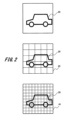
- FIG. 2 is a diagram showing a comparison of the surroundings of a subject, a coarse distance image, and a detailed distance image.
- FIG. 2 is a diagram illustrating a comparison of resolutions of information stored in the first camera image 21, the second camera image 31, the coarse distance image 45, and the detailed distance image 46.
- the resolution here means not the distance in the depth direction but the height of the resolution in the vertical and horizontal directions on the image.
- the coarse distance image 45 and the detailed distance image 46 are examples of the distance image 41 shown in FIG.
- FIG. 2 The upper part of FIG. 2 is a diagram showing the surroundings of the vehicle 10, where another vehicle 20 is present.
- the middle part of FIG. 2 is a conceptual diagram showing the resolution of the coarse distance image 45 taken of the vehicle 20, and the bottom part of FIG. 2 is a conceptual diagram showing the resolution of the detailed distance image 46, which has a higher resolution than the coarse distance image 45.
- the coarse distance image 45 shown in the middle part of FIG. 2 stores distance information for each of a total of 25 image areas obtained by dividing the area shown in the upper part of FIG. 2 into 5 vertically and horizontally.
- the detailed distance image 46 shown in the lower part of FIG. 2 stores distance information for each of a total of 100 image regions obtained by dividing the region shown in the upper part of FIG. 2 into 10 vertically and horizontally.
- the top and bottom of the illustrated image correspond to the vertical direction
- the left and right sides of the illustrated image correspond to the horizontal direction.
- the image area indicated by one piece of distance information included in the coarse distance image 45 is called a "first image block", and as shown in the bottom part of FIG.
- the image area indicated by one piece of distance information is called a "second image block.”
- the size of the first image block (first size) is larger than the size of the second image block (second size).
- the first image block has twice the width and twice the height, and four times the area, compared to the second image block.
- the first image block is larger than the second image block, and the multiple is not particularly limited.
- the distance information of one point is not necessarily the distance information obtained by measuring the entire first image block, but in this embodiment, the distance information is conveniently distance information representative of the entire first image block. It is regarded as Furthermore, it is also known which first image block in the coarse distance image 45 each of the second image blocks in the detailed distance image 46 is included in.
- Each of the first camera image 21 and the second camera image 31 has information on brightness and saturation with a resolution equal to or higher than that of the second image block.
- each of the first camera image 21 and the second camera image 31 has information of at least 10 pixels both vertically and horizontally in the range shown in the upper part of FIG. 2, that is, 100 pixels or more in total.
- the first camera image 21 and the second camera image 31 may have substantially the same number of pixels as the detailed distance image 46, or may have double or ten times as many pixels in the vertical and horizontal directions. In this embodiment, as an example, the first camera image 21 and the second camera image 31 have approximately the same number of pixels as the detailed distance image 46.
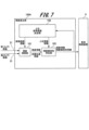
- FIG. 3 is a block diagram showing an example of the functional configuration of the arithmetic device 1.
- the arithmetic device 1 includes a disparity calculation unit 100 that includes a disparity search unit 101, a higher reference disparity determination unit 102, and a disparity invalidity determination unit 103.
- the functions of the disparity search unit 101, the upper reference disparity determination unit 102, and the disparity invalidity determination unit 103 of the disparity calculation unit 100 are realized by software processing by the CPU 11 described above. Note that information generated by the processing described below, such as search range information, disparity information, dissimilarity information, upper disparity information, disparity invalidity information, and search range change instruction, is temporarily stored in the RAM 13. .
- the parallax calculation unit 100 may generate a distance image (for example, a coarse distance image 45, a detailed distance image 46, etc.) based on the parallax information of the two images and output it to the vehicle control device 4.
- a distance image for example, a coarse distance image 45, a detailed distance image 46, etc.
- the parallax calculation unit 100 calculates parallax information and outputs it to the vehicle control device 4.
- a first camera image 21 (left image) and a second camera image 31 (right image) captured by the left camera 21 and the right camera 31 from different viewpoints are input to the parallax calculation unit 100.
- the disparity search unit 101 performs a disparity search (disparity determination) by comparing two images, the first camera image 21 and the second camera image 31, and provides "disparity information" as a search result, which is used for disparity determination. Output "dissimilarity information".
- stereo matching processing can be used for this search processing.
- the image blocks to be compared in each of the two images are shifted one pixel at a time and matched.
- the stereo matching process here is an example of the first layer stereo matching process. If the disparity generated at this time is not the highest disparity in the hierarchical search (for example, see Patent Document 1), the disparity search unit 101 obtains “search range information” from the high-level reference disparity determination unit 102 and determines the range.
- a local search is performed to search only within the area. This local search process is an example of second-layer stereo matching process. Note that in the following description, the parallax search is also simply referred to as a "search.”
- the above search range information is a search range (pixel This is information about the pixels at the start and end points that determine the amount of shift).
- the search width is determined from the starting point and ending point. Generally, the higher the resolution of the image, the wider the search width.
- the highest parallax is the parallax searched from the lowest resolution image when hierarchical images with multiple resolutions are generated from the camera image (original image).
- the disparity search unit 101 determines disparity so that the degree of dissimilarity is minimized.
- Information on the determined parallax (information representing the position of the parallax on the image) is sent to the parallax invalidity determining unit 103 together with dissimilarity information.
- the disparity invalidity determination unit 103 refers to the “dissimilarity information” output from the disparity search unit 101 and determines whether the disparity determined by the disparity search unit 101 is located at the edge of the local search range. do. Here, if the determined position of the disparity is an edge, the disparity invalidity determination unit 103 considers that there is a high possibility that a point with a lower degree of dissimilarity exists outside the local search range, that is, a true disparity. Then, the disparity search unit 101 is instructed to change (for example, extend) the local search range outside the edge of the local search range where the determined disparity is located and search again (“search range change instruction” in the figure). put out.
- the search range and extension width after extension are determined in advance for each condition such as image hierarchy (resolution), and registered in the parallax calculation unit 100 (for example, ROM 12). .
- the degree of extension of this local search range differs for each image layer depending on, for example, allowable search time and cost.
- the search time varies depending on the processing capacity of the arithmetic device 1, the data size of the camera image, and the like.
- the maximum extension width of the local search range is determined by the circuit scale (processing capacity) of the arithmetic device 1.
- the disparity search unit 101 performs a re-search in response to the search range change instruction from the disparity invalidity determination unit 103, and re-outputs the point where the degree of dissimilarity is minimum including the extended search range as disparity.
- an upper limit may be set on the search range to be extended, taking into account the amount of calculation and calculation time of the calculation device 1. That is, in the arithmetic device 1, when performing a search by widening the first search width (search width of upper hierarchy) or the second search range (search range of lower hierarchy), the first search width or the second search width is expanded. An upper limit is set in advance for the search range. According to this embodiment configured in this way, by setting an upper limit to the first search width or the second search range, it is possible to reduce the amount of calculations and the calculation time of the calculation device 1.
- the disparity search unit 101 may terminate the search there and output the point of the first minimum value as the disparity. That is, when the disparity search unit 101 performs a search by widening the first search width (search width for upper layers) or the second search range (search range for lower layers), the disparity search unit 101 determines whether the degree of similarity increases along the search direction.
- the search can be configured to be terminated based on the reduced number of points. According to the present embodiment configured in this way, by determining the disparity based on the point where the degree of similarity decreases along the search direction, it is possible to reduce the amount of calculation and the calculation time of the calculation device 1. Become.
- minimum and minimum in this specification, the terms “minimum” and “minimum” in a strictly mathematical sense include substantial minimums and “minimum”.
- the local minimum point corresponds to a location where the differential value is 0 or less than a predetermined value (for example, a small value close to 0).
- the parallax search unit 101 determines that an image block with the highest degree of similarity to the first image block exists at the end of the first search range.
- the first search width or the second search range can be determined based on which end of the first search range the image block with the highest degree of similarity was found. According to this embodiment configured in this way, the first search width or By determining the second search range, it is possible to search for disparities with higher similarity.
- the "disparity information" and "dissimilarity information" of the re-search results are sent again from the disparity search unit 101 to the disparity invalidity determination unit 103.
- the parallax invalidity determination unit 103 may directly send the results of the re-search performed by the parallax search unit 101 to the vehicle control device 4 as “disparity information” and “parallax invalidity (valid/invalid) information”.
- the parallax invalidity determination unit 103 may perform the determination for re-search again.
- the basic concept of validity/invalidity is that if the position of the parallax determined above is not at the edge of the local search range, the parallax is valid, and if the position of the determined parallax is at the edge of the local search range. , the parallax is determined to be invalid.
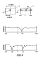
- FIG. 4 is a diagram illustrating the concept of disparity determination by the disparity search unit 101 of the disparity calculation unit 100.
- the first camera image 21 and the second camera image 31 are shown in the upper part of FIG. 4 .
- the reference image that is, the image area of the second camera image 31, corresponding to the image area 201 of the first camera image 21, which is the reference image, is searched. Note that although the first camera image 21 is used as the reference image, the second camera image 31 may also be used as the reference image.
- the left camera 2 and the right camera 3 are installed side by side in the horizontal direction, so the epipolar line 202 due to epipolar geometry is shown as a broken line extending in the horizontal direction.
- the width of the first camera image 21 and the second camera image 31 in the illustrated horizontal direction is 1000 pixels, and the center of the image area 201 is the 400th pixel from the left end of the first camera image 21, the second camera image that is the reference image In the horizontal direction of the camera image 31, numerical values from -400 to +600 are assigned as shown.
- the parallax search unit 101 determines that the image area 203 centered on 500 pixels from the left end of the reference image corresponds to the image area 201 of the reference image, the parallax is calculated as "100".
- the middle part of FIG. 4 is a diagram showing an example of the degree of dissimilarity between the reference image (second camera image 31) and the image region 201 for each position on the epipolar line 202.
- the lower part of FIG. 4 is a diagram showing another example of the degree of dissimilarity between the reference image (second camera image 31) and the image region 201 for each position on the epipolar line 202.
- the parallax search unit 101 regards the image area 201 as an invalid area and sets parallax "0" to the position corresponding to the image area 201 in the distance image 41.
- a related invention in which there are a plurality of peaks with the minimum degree of dissimilarity is shown in a third embodiment described later.
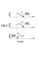
- FIG. 5 is a diagram showing an example of local re-search determination and an example of the search range extension direction during re-search according to the first embodiment of the present invention.
- the horizontal axis of the graph in the figure is the position (corresponding to the amount of pixel shift) when comparing both the first camera image 21 and the second camera image 31, and the vertical axis is the dissimilarity of the comparison result. .
- the area between the two dashed lines indicates the local search range.
- the disparity search unit 101 outputs the disparity 501 at the right end of the local search range, but also outputs the five dissimilarities calculated here (including the dissimilarity corresponding to the disparity 501).
- the disparity invalidity determination unit 103 acquires the five dissimilarities along with the disparity 501 from the disparity search unit 101, thereby determining that the disparity 501 is located at the right end of the local search range, that is, the disparity 501 is invalid. Can be judged. Therefore, the parallax 501 is subject to a search range change instruction by the parallax invalidity determining unit 103.
- the disparity search unit 101 may output that the output disparity is at the end or right end of the local search range.
- the parallax invalidity determining unit 103 can determine from this information that the parallax output by the parallax searching unit 101 is at the end (here, the right end) within the local search range.
- the extension direction of the search range at the time of re-search is to the right (direction in which the amount of pixel shift increases).
- the parallax 502 is subject to a search range change instruction by the parallax invalidity determining unit 103.
- the extension direction of the search range during re-search is to the right (direction in which the pixel shift amount increases).
- the lower graph in FIG. 5 shows that the dissimilarity of disparities within the local search range does not monotonically increase but has local maximum and minimum values, but the dissimilarity of disparity 503 located at the left end of the local search range is the minimum value. be. Therefore, the parallax 503 is subject to a search range change instruction by the parallax invalidity determining unit 103.
- the extension direction of the search range during re-search is to the left (direction in which the amount of pixel shift decreases).
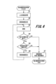
- FIG. 6 is a flowchart illustrating an example of a procedure of local search processing for the Nth layer of hierarchical search by the parallax calculation unit 100 of the first embodiment.
- the upper reference disparity determination section 102 refers to the disparity of the N-1st layer (lower resolution) that is higher than the Nth layer obtained from the disparity invalidity determination section 103 (step S1), an initial search range in the Nth layer is determined (step S2). Note that if the Nth layer is the highest layer (lowest resolution), the search range is set in advance and stored in the ROM 12.
- the disparity search unit 101 sets the initial search range determined by the upper reference disparity determination unit 102 as the search range for the local search, and performs a local search for the search range (step S3).
- the parallax invalidity determination unit 103 determines whether the point with the minimum degree of dissimilarity is located at the end of the search range based on the search results by the parallax search unit 101 (step S4).
- the disparity invalidity determination unit 103 determines the disparity and disparity validity/invalidity (in this case, valid). and outputs it (step S7).
- the parallax and parallax valid/invalid information are output to the vehicle control device 4 and the higher-order reference parallax determining unit 102.
- the parallax invalidity determination unit 103 determines that the number of re-searches is within the preset upper limit of the number of re-searches. It is determined whether or not (step S5). If the number of re-searches is within the preset upper limit of the number of re-searches (YES in step S5), the parallax invalidity determining unit 103 issues a search range change instruction to the parallax searching unit 101. Note that although the determination process in step S5 was provided in consideration of the allowable processing time, it may be deleted.
- parallax search unit 101 when the parallax search unit 101 receives the search range change instruction, it modifies the search range during the local search in step S3 (step S6), and searches for parallax again (step S3).
- step S4 After determining YES in step S4, if the parallax invalidity determination unit 103 determines that the number of re-searches has reached the preset upper limit of the number of re-searches (NO in step S5), the parallax and parallax validity/invalidity are determined. is determined and output (step S7). After the process in step S7, the local search process for the Nth layer of the hierarchy search is ended.
- the image processing device can process two images (first camera image 21, second camera image 21,
- This image processing device includes a parallax calculation unit (parallax calculation unit 100) that calculates parallax by comparing images 31).
- the parallax calculation unit is configured to calculate an image block (for example, an image) that has the highest degree of similarity to a first image block (for example, image area 201) that is an image area of a first size and is included in one of the two images.
- the first layer stereo matching process (local search in the upper layer) that calculates the first parallax for each image area, and the second image area that is smaller than the first size and is one of the two images.
- a second search range is determined based on the first parallax of the other image of the two images and a predetermined second search width.
- the parallax calculation unit calculates the first search width or The search is performed by expanding the second search range (eg, based on the modified (extended) local search range).
- this embodiment even if the parallax is determined to be invalid, the local search range (or search width) is changed and the search is performed again. Therefore, this embodiment not only calculates the true minimum value (or local minimum value) of dissimilarity (or similarity) from two images, but also provides feedback to the same or lower hierarchy in the hierarchy search, and once Even if an invalid determination is made, effective parallax can be efficiently searched for without increasing the calculation load.
- the second embodiment is an example configured to output an invalid determination for the relevant layer when the degree of dissimilarity of parallax reaches the minimum value at the edge of the local search range.
- the second embodiment will be described below, focusing mainly on the differences from the first embodiment.
- FIG. 7 is a block diagram illustrating an example of a functional configuration of a parallax calculation unit in a calculation device (an example of an image processing device) according to the second embodiment of the present invention.
- the arithmetic device 1 includes a disparity calculation unit 100A that includes a disparity search unit 101, a higher reference disparity determination unit 102, and a disparity invalidity determination unit 103.
- the disparity calculation unit 100A of the arithmetic device 1 according to the present embodiment searches from the upper reference disparity determination unit 102 to the disparity search unit 101, compared to the disparity calculation unit 100 (FIG. 3) according to the first embodiment. The difference is that there is no signal line to issue range change instructions.
- the parallax search unit 101 receives a first camera image 21 (left image) and a second camera image 31 (right image) captured by the left camera 21 and the right camera 31 from different viewpoints. is input.
- the disparity search unit 101 performs a disparity search (disparity determination) by comparing two images, the first camera image 21 and the second camera image 31, and determines the disparity as the search result. information" and "dissimilarity information" used for determining parallax.
- the search process here is an example of the first layer stereo matching process. If the disparity generated at this time is not the highest disparity in the hierarchical search (for example, see Patent Document 1), the disparity search unit 101 obtains “search range information” from the high-level reference disparity determination unit 102 and determines the range. A local search is performed to search only within the area. This local search process is an example of second-layer stereo matching process.
- the disparity search unit 101 determines disparity so that the degree of dissimilarity is minimized.
- Information on the determined parallax (information representing the position of the parallax on the image) is sent to the parallax invalidity determining unit 103 together with dissimilarity information.
- the disparity invalidity determination unit 103 refers to the “dissimilarity information” output from the disparity search unit 101 and determines whether the disparity determined by the disparity search unit 101 is located at the edge of the local search range. do. Here, if the determined position of the disparity is an edge, the disparity invalidity determination unit 103 considers that there is a high possibility that a point with a lower degree of dissimilarity exists outside the local search range, that is, a true disparity. Then, the parallax is determined to be invalid.
- the parallax invalidity determination unit 103 outputs the “disparity information” output from the parallax search unit 101 and the “parallax invalidity (valid/invalid) information” to the vehicle control device 4 and the higher-order reference parallax determination unit 102.
- the disparity determined to be invalid here is referred to as an upper disparity during a local search of a lower hierarchy, but if the invalid disparity remains, all lower disparities are determined to be invalid. At that time, for example, by locally searching around the search range of the adjacent upper disparity using the method described in Japanese Patent Application Laid-open No. 2020-140344, the invalid determination can be avoided and the lower disparity can be output. may be possible.
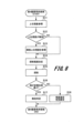
- FIG. 8 is a flowchart illustrating an example of the procedure of local search processing for the Nth layer of hierarchical search performed by the disparity calculation unit 100A of the second embodiment.
- the upper reference disparity determination unit 102 refers to the disparity of the N-1st layer (lower resolution) that is higher than the Nth layer obtained from the disparity invalidity determination unit 103 (step S11 ). Then, the upper reference disparity determining unit 102 determines the initial search range in the Nth layer.
- step S12 determines whether the upper parallax is invalid (step S12), and if the upper parallax is not invalid (NO in step S12), the process proceeds to step S14.
- step S12 If it is determined in step S12 that the upper disparity is invalid (YES in step S12), the upper reference disparity determination unit 102 switches the reference destination to the disparity in the upper layer adjacent to the upper disparity (step S13).
- the parallax search unit 101 sets a search range for local search. If the determination is NO in step S12, the disparity search unit 101 sets the initial search range determined by the upper reference disparity determination unit 102 as the search range for the local search (step S14). Further, after the processing in step S13, the disparity search unit 101 sets a search range for local search around the adjacent disparity in the upper layer referred to by the upper reference disparity determination unit 102 (step S14).
- the parallax search unit 101 performs a local search for the set local search search range (step S15).
- the parallax invalidity determination unit 103 determines whether the point with the minimum degree of dissimilarity is located at the end of the search range based on the search results by the parallax search unit 101 (step S16).
- the disparity invalidity determination unit 103 determines and outputs the disparity and the disparity validity (step S18). .
- the disparity invalidity determining unit 103 determines that the disparity is invalid and outputs the determination result (step S17). ).
- the parallax and parallax valid/invalid information are output to the vehicle control device 4 and the higher-order reference parallax determining unit 102.
- step S16 the process of determining whether the number of re-searches in step S5 of FIG. 3 described in the first embodiment is within the upper limit may be provided after the process of step S16.
- the invalidity determination described in this embodiment does not need to be uniform for all local searches.
- the present invention Turn off the function that changes the local search range when determining that parallax is invalid (hereinafter referred to as "this function"), and conversely turn this function off at a relatively lower level where a narrow range is searched in one search due to high resolution. It is also possible to operate by turning it on.
- the parallax search unit 101 calculates the first search width (search width of the upper layer) based on the size of the first image block (image block of the camera image of the upper layer). ) or expand the second search range (lower hierarchy search range) to determine whether to perform the search. According to this embodiment with such a configuration, it is possible to efficiently perform a parallax search depending on the size of the first image block included in one of the two images.
- the disparity search unit 101 calculates the similarity difference within the first search range in the search in the first layer stereo matching process (local search in the upper layer). It can be configured to determine whether to perform a search by widening the first search width or the second search range based on whether or not the value is larger than a predetermined threshold. According to this embodiment with such a configuration, it is possible to efficiently perform a parallax search according to the difference in similarity within the first search range.
- this function is turned on when the dissimilarity of the disparity near the edge of the minimum value within the local search range differs by a predetermined amount or more compared to the dissimilarity of other disparities. Such operations are also possible.
- the parallax invalidity determination unit 103 determines whether the similarity of the image block with the highest degree of similarity is , whether to perform the search by widening the first search width or the second search range based on whether there is a difference greater than a predetermined threshold compared to the similarity of other image blocks within the search range; It can be configured to determine which According to this embodiment with such a configuration, it is possible to efficiently perform a parallax search according to the difference in similarity within the first search range.
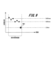
- FIG. 9 is a diagram showing an example of the magnitude of dissimilarity within the local search range in the second embodiment of the present invention.
- the smaller of the dissimilarities between the left and right ends of the local search range is set as "LRmin”
- the maximum of the dissimilarities excluding the left and right ends is set as "SADmax”
- the minimum is set as "SADmin”.
- Th0 is determined, and the parallax invalidity determination unit 103 determines whether the following formula (1) holds true and turns on this function when formula (1) holds true. You may.
- parallax invalidity determination unit 103 determines whether the following formula (2) holds true by predetermining a threshold value Th1, and turns on this function when formula (2) holds true. Good too.
- the reason for this operation is that from large fluctuations in dissimilarity within the local search range, it can be inferred that there are points with smaller dissimilarity around the local search range.
- the parallax invalidity determination unit 103 determines whether or not the following formula (3) holds, and turns on this function when the formula (3) holds. Good too.
- the parallax invalidity determination unit 103 determines whether the luminance gradient (gradient of dissimilarity; for example, SADmin-LRmin, SADmax-LRmin, or SADmax-SADmin) within the image block is a predetermined threshold value. (for example, Th0, Th1, or Th2), the first search width (search width of upper layer) or the second search range (search range of lower layer) is expanded and the search is performed. It can be configured to determine whether or not. According to this embodiment with such a configuration, it is possible to efficiently perform a parallax search according to the luminance gradient within an image block.
- a predetermined threshold value for example, Th0, Th1, or Th2
- the first search width search width of upper layer
- the second search range search range of lower layer
- the disparity invalidity determination unit 103 determines whether the first disparity obtained in the first layer stereo matching process (upper layer local search) is larger than a predetermined threshold.
- the first search width or the second search range may be expanded to determine whether or not to perform the search. According to this embodiment with such a configuration, it is possible to efficiently perform a parallax search depending on the distances from the two cameras to the object (the relationship between the first parallax and the threshold value).
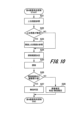
- FIG. 10 is a flowchart illustrating an example of the procedure of local search processing for the Nth layer of hierarchical search performed by the disparity calculation unit 100A of the third embodiment.
- the parallax calculation unit 100A according to this embodiment can have the same configuration as the parallax calculation unit 100A according to the second embodiment.
- the processing in steps S21 to S25 in FIG. 10 is the same as the processing in steps S11 to S15 in FIG. 8 in the second embodiment, so a description thereof will be omitted.
- the upper reference disparity determination unit 102 and the disparity search unit 101 execute the processes of steps S21 to S25.
- the parallax invalidity determination unit 103 determines whether or not there are multiple minimum values of dissimilarity within the local search range based on the search results by the parallax search unit 101 (step S26). .
- the parallax invalidity determination unit 103 determines the position of the minimum value within the local search range (distance to the edge). is closer than the threshold value), and determines the parallax and whether the parallax is valid or invalid and outputs it (step S28).
- the disparity invalidity determination unit 103 determines that the disparity is invalid and outputs the determination result (step S27). .
- the parallax and parallax valid/invalid information are output to the vehicle control device 4 and the upper reference parallax determining unit 102.
- the image processing device (computing device 1) according to the third embodiment detects a plurality of image blocks that are similar to the first image block. If it exists, the configuration can be such that as a result of the first layer stereo matching process, the first parallax is not output, and the second layer stereo matching process (lower layer local search) is performed.
- the obtained parallax is determined to be invalid, and the second layer stereo matching process is performed. Since stereo matching processing (local search of lower layers) is performed, it is possible to avoid invalidating all the corresponding lower-order parallaxes and increase the possibility of parallax calculation.
- the parallax invalidity determination unit 103 uses the configuration of the second embodiment to determine whether the luminance gradient within the image block is larger than a predetermined threshold. It can be configured to determine whether to output one parallax. According to this embodiment with such a configuration, it is possible to efficiently perform a parallax search according to the luminance gradient within an image block.
- the present invention is not limited to the embodiments described above, and it goes without saying that various other applications and modifications may be made without departing from the gist of the present invention as set forth in the claims.
- the configurations thereof are explained in detail and specifically in order to explain the present invention in an easy-to-understand manner, and the embodiments are not necessarily limited to those having all the explained components.
- processing steps describing chronological processing are not only processes that are performed chronologically in the described order, but also processes that are not necessarily performed chronologically, but may be performed in parallel or It also includes processes that are executed individually (for example, processes by objects).
- control lines and information lines are shown that are considered necessary for explanation, and not all control lines and information lines are necessarily shown in the product. In reality, almost all the components may be considered to be interconnected.
Landscapes
- Engineering & Computer Science (AREA)
- Computer Vision & Pattern Recognition (AREA)
- Physics & Mathematics (AREA)
- General Physics & Mathematics (AREA)
- Theoretical Computer Science (AREA)
- Image Analysis (AREA)
- Image Processing (AREA)
- Measurement Of Optical Distance (AREA)
Abstract
本発明の一態様に係る画像処理装置は、2つの画像のうち一方の画像に含まれる第一画像ブロックと類似度の高い画像ブロックを、他方の画像のうち所定の第一の探索幅に基づく第一の探索範囲から特定し、第一の大きさの画像領域単位で第一の視差を求める第一階層のマッチング処理と、他方の画像のうち第一の視差及び所定の第二の探索幅に基づく第二の探索範囲から特定することで、第二の大きさの画像領域単位で第二の視差を求める第二階層のマッチング処理と、を行い、第一階層のマッチング処理において、第一の探索範囲内の端で、第一画像ブロックと類似度の高い画像ブロックが存在する場合に、第一の探索幅又は第二の探索範囲を広げて探索を行う。
Description
本発明は、撮影装置で撮影された画像を用いて、車両の周辺に存在する対象物を監視する画像処理装置及び画像処理方法に関する。
一対のカメラを有するステレオカメラで撮影されたステレオ画像に基づき、カメラ視野内に存在する物体までの距離を三角測量の原理で計測する位置測定装置が知られている。
三角測量の原理とはすなわち、左右のカメラによって撮影された同一の物体の像の位置のずれ(視差)を用いて、カメラからその物体までの距離を算出するものである。視差の導出は、物体の一方の画像上における像が、他方の画像上のどこに存在するかを特定することによって実現する。
三角測量の原理とはすなわち、左右のカメラによって撮影された同一の物体の像の位置のずれ(視差)を用いて、カメラからその物体までの距離を算出するものである。視差の導出は、物体の一方の画像上における像が、他方の画像上のどこに存在するかを特定することによって実現する。
視差の導出方法としては様々な手法が提案されている。例えば、古典的手法では、一方の画像中の複数画素からなる画像領域に対して、他方の画像中で最も非類似度の低い画像領域を探索するブロックマッチングが知られている。
近年、こうした測距結果が車両の自動運転(AD)や高度運転支援(ADAS)などに用いられる。自動運転では、より遠方の路上落下物の検知や、穴、隆起等の路面状態の把握が必須となる。しかし、遠方の物体は近方の物体と比べて、画像上より少数の画素から構成されるため、より高精細な距離情報が必要となる。そのために、視差の導出にかかる演算量や演算時間が増大するという課題がある。
演算量や演算時間の増大に対する対策としては、まず低解像度の視差画像を作成しておき、より高精細な視差の探索には対応する低解像度の視差、すなわち上位視差の周辺のみを探索する階層探索が知られている(特許文献1を参照)。
特許文献1では、より高解像度(下位)の視差を算出するために、予め算出した低解像度(上位)の視差周辺のみを探索することで、計算量や計算時間の縮減を図っている。一方、視差の探索にあたっては、例えば、視差探索範囲内の端で左右画像の画像内領域の非類似度が最小となって、探索範囲外に真の視差が存在することが予想されるなどを理由にして、算出された視差の信頼度を低いとみなして当該視差を無効とすることがある。階層探索において、より低解像度の視差が無効とみなされた場合、この低解像度の視差に対応する高解像度の視差は探索できず、すべて無効となる。そのため、最終的な高解像度の視差画像において大量の無効視差が発生する場合があるという課題がある。
上記の状況から、階層探索において上位の視差が無効と判定された場合に、対応する下位の視差すべてを無効とすることを避け、視差算出の可能性を高める手法が要望されていた。
上記課題を解決するために、本発明の一態様の画像処理装置は、2つのカメラで撮像された2つの画像を比較して視差を求める視差算出部を備えた画像処理装置である。
上記視差算出部は、第一の大きさの画像領域であり2つの画像のうち一方の画像に含まれる第一画像ブロックと最も類似度の高い画像ブロックを、2つの画像の他方の画像のうち予め定められた第一の探索幅に基づいて決められる第一の探索範囲から特定することで、第一の大きさの画像領域単位で第一の視差を求める第一階層のステレオマッチング処理と、第一の大きさより小さい第二の大きさの画像領域であり2つの画像のうち一方の画像に含まれる第二画像ブロックと最も類似度の高い画像ブロックを、2つの画像の他方の画像のうち第一の視差及び予め定められた第二の探索幅に基づいて決められる第二の探索範囲から特定することで、第二の大きさの画像領域単位で第二の視差を求める第二階層のステレオマッチング処理と、を行う。そして、視差算出部は、第一階層のステレオマッチング処理において、第一の探索範囲内の端で、第一画像ブロックと最も類似度の高い画像ブロックが存在する場合に、第一の探索幅又は第二の探索範囲を広げて、探索を行う。
ここで、探索範囲は、探索幅を決める探索の始点と終点の情報である。
本発明の少なくとも一態様によれば、階層探索において上位の視差が無効と判定された場合に、対応する下位の視差すべてを無効とすることを避け、視差算出の可能性を高めることができる。
上記した以外の課題、構成及び効果は、以下の実施形態の説明により明らかにされる。
上記した以外の課題、構成及び効果は、以下の実施形態の説明により明らかにされる。
以下、本発明を実施するための形態(以下、「実施形態」と称する)の例について、添付図面を参照して説明する。本明細書及び添付図面において、同一の構成要素又は実質的に同一の機能を有する構成要素には同一の符号を付して重複する説明を省略する。また、同一あるいは同様の機能を有する構成要素が複数ある場合には、同一の符号に異なる添字を付して説明する場合がある。また、これらの複数の構成要素を区別する必要がない場合には、添字を省略して説明する場合がある。
<第1の実施形態>
まず、本発明の第1の実施形態に係る演算装置(画像処理装置の一例)について図1~図6を参照して説明する。
まず、本発明の第1の実施形態に係る演算装置(画像処理装置の一例)について図1~図6を参照して説明する。
図1は、車両内の制御系のハードウェア構成例を示す図である。図1に示す車両10は、演算装置1と、左カメラ2と、右カメラ3と、車両制御装置4とを備える。演算装置1及び車両制御装置4は、電子制御装置(Electronic Control Unit:ECU)である。左カメラ2及び右カメラ3は、車両10の周囲を撮影して得られた撮影画像を演算装置1に出力する。左カメラ2及び右カメラ3は、水平方向に並んで配置される。以下では、左カメラ2の撮影画像を第1カメラ画像21、右カメラ3の撮影画像を第2カメラ画像31と呼ぶ。また、左カメラ2を「第1のカメラ」と呼び、右カメラ3を「第2のカメラ」と呼ぶこともある。
左カメラ2及び右カメラ3は水平方向を向くように配置されるので、第1カメラ画像21(左画像)及び第2カメラ画像31(右画像)のいずれも、鉛直方向及び水平方向に広がりのある3次元空間を撮影して得られた画像である。ただし、ここでいう水平や垂直は厳密な意味ではなく、第1カメラ画像21及び第2カメラ画像31の左右方向が天地ではなく水平方向に対応するという程度の意味である。例えば、左カメラ2および右カメラ3が光軸を回転中心として最大で30度程度傾いてもよい。
演算装置1は、中央演算装置であるCPU11、読み出し専用の記憶装置であるROM12、読み書き可能な記憶装置であるRAM13、及び第1カメラ画像21や第2カメラ画像31を受信するインタフェース14を備える。CPU11がROM12に格納されるコンピュータープログラムをRAM13に展開して実行することで、演算装置1の後述する複数の機能が実現される。ROM12の代わりに、図示しない不揮発性ストレージにコンピュータープログラムを格納してもよい。ROM12及び不揮発性ストレージは、当該プログラムを格納したコンピューター読取可能な非一過性の記録媒体の一例として用いられる。
ただし、演算装置1は、CPU11、ROM12、及びRAM13の組合せの代わりに、書換え可能な論理回路であるFPGA(Field Programmable Gate Array)や特定用途向け集積回路であるASIC(Application Specific Integrated Circuit)により、それらの一部又はすべての機能が実現されてもよい。また、演算装置1は、CPU11、ROM12、及びRAM13の組合せの代わりに、異なる構成の組合せ、例えば、CPU11、ROM12、RAM13とFPGAの組合せにより実現されてもよい。
インタフェース14は、第1カメラ画像21(左画像)及び第2カメラ画像31(右画像)を受信し、CPU11に提供する。ただし、CPU11に備えられるレジスタにはわずかな情報しか格納できないので、CPU11が自由にそれらの情報を参照できるように、インタフェース14は受信した第1カメラ画像21及び第2カメラ画像31をRAM13に格納する。
演算装置1は、入力される第1カメラ画像21(左画像)及び第2カメラ画像31(右画像)を用いて、視差に基づいた車両10周辺の物体までの距離情報を含む距離画像41(図2参照)を作成し、車両制御装置4に出力する。演算装置1が距離画像41を作成する過程は、図2以降を参照して後に詳述する。距離画像41とは、二次元平面における距離の遠近を色の濃淡や色の彩度で表したものである。ただし、本実施形態では、距離画像41の各画素には濃淡を表す「0」~「255」の整数値が格納される。このうち「0」は、距離の算出が不可能であったことを示す特別な数値である。
距離画像41に示される範囲は、第1カメラ画像21(左画像)及び第2カメラ画像31(右画像)と略同一である。ただし、距離画像41に示される範囲は、第1カメラ画像21及び第2カメラ画像31に示される範囲よりも狭くてもよい。距離画像41の画素数は、第1カメラ画像21及び第2カメラ画像31と略同一でもよいし、第1カメラ画像21及び第2カメラ画像31の画素数よりも少なくてもよい。
すなわち、第1カメラ画像21(左画像)、及び第2カメラ画像31(右画像)に記録されている三次元空間は、少なくとも一部が重複していればよい。左カメラ2、及び右カメラ3の車両10における取り付け位置や取り付け姿勢は既知であり、第1カメラ画像21、及び第2カメラ画像31の相互の位置関係も既知である。そのため、第1カメラ画像21における所定の画素の三次元空間における位置が、第2カメラ画像31のどの位置に相当するかも既知である。第1カメラ画像21及び第2カメラ画像31の相互の位置関係は、演算で求めてもよいし、予めルックアップテーブルなどを用意して参照して求めてもよい。
すなわち、左カメラ2と右カメラ3の相対位置は既知であり、2つのカメラの内部パラメータも既知なので、被写体のカメラまでの距離と視差の関係も既知である。本実施形態では、距離と視差の関係は、不図示の視差テーブルとして演算装置1のROM12に格納される。本実施形態では、距離と視差の関係は既知なので、視差は「距離に対応する情報」と呼ぶこともできる。また、本実施形態では、距離と視差は相互に容易に変換可能なので、両者は実質的に同一の情報とみなせる。
車両制御装置4は、演算装置1から入力される距離画像41を用いて車両10を制御する。車両制御装置4は、例えば、距離画像41から車両10の周辺に存在する障害物を検出し、車両10と検出した障害物との衝突を避けるように車両10を制御する。車両制御装置4による車両10の制御は、例えば、車両制御装置4が、不図示の操舵装置及び不図示の制動装置に動作指令を出力することにより実現される。
[車両周辺の様子、粗距離画像、及び詳細距離画像]
図2は、被写体周辺の様子、粗距離画像、及び詳細距離画像の比較を示す図である。
図2は、第1カメラ画像21、第2カメラ画像31、粗距離画像45、及び詳細距離画像46に格納される情報の解像度の比較を説明する図である。ただし、ここでいう解像度とは、奥行き方向の距離ではなく、画像上の上下方向や左右方向の分解能の高さを意味する。なお、粗距離画像45と詳細距離画像46は、図1に示した距離画像41の一例である。
図2は、被写体周辺の様子、粗距離画像、及び詳細距離画像の比較を示す図である。
図2は、第1カメラ画像21、第2カメラ画像31、粗距離画像45、及び詳細距離画像46に格納される情報の解像度の比較を説明する図である。ただし、ここでいう解像度とは、奥行き方向の距離ではなく、画像上の上下方向や左右方向の分解能の高さを意味する。なお、粗距離画像45と詳細距離画像46は、図1に示した距離画像41の一例である。
図2上段は車両10の周辺の様子を示す図であり、他の車両20が存在している。図2中段は車両20を撮影した粗距離画像45の解像度を示す概念図、図2下段は粗距離画像45よりも解像度が高い詳細距離画像46の解像度を示す概念図である。
図2中段に示す粗距離画像45には、図2上段に示す領域を縦と横のそれぞれを5分割した合計25個の画像領域ごとの距離情報が格納される。
図2下段に示す詳細距離画像46には、図2上段に示す領域を縦と横のそれぞれを10分割した合計100個の画像領域ごとの距離情報が格納される。粗距離画像45及び詳細距離画像46は、図示画像の上下が天地方向に、図示画像の左右が水平方向に対応する。
本実施形態では、図2中段に示すように粗距離画像45に含まれる1つの距離情報が示す画像領域を「第一画像ブロック」と呼び、図2下段に示すように詳細距離画像46に含まれる1つの距離情報が示す画像領域を「第二画像ブロック」と呼ぶ。第一画像ブロックの大きさ(第一の大きさ)は第二画像ブロックの大きさ(第二の大きさ)よりも大きい。
図2に示す例及び本実施形態では、第一画像ブロックは第二画像ブロックに比べて幅と高さがそれぞれ2倍であり、面積は4倍である。ただし、第一画像ブロックが第二画像ブロックよりも大きければよく、倍数は特に制限されない。
図2に示す例及び本実施形態では、第一画像ブロックは第二画像ブロックに比べて幅と高さがそれぞれ2倍であり、面積は4倍である。ただし、第一画像ブロックが第二画像ブロックよりも大きければよく、倍数は特に制限されない。
なお、1点の距離情報は、必ずしも第一画像ブロック全体を測定して得られた距離情報ではないが、本実施形態では、その距離情報が便宜的に第一画像ブロック全体を代表する距離情報とみなしている。また、詳細距離画像46における第二画像ブロックのそれぞれが、粗距離画像45におけるいずれの第一画像ブロックの領域内に含まれるかも既知である。
第1カメラ画像21及び第2カメラ画像31のそれぞれは、第二画像ブロックと同等以上の解像度で輝度や彩度の情報を有する。図2の例に即すると、第1カメラ画像21及び第2カメラ画像31のそれぞれは、図2上段に示す範囲について縦と横ともに少なくとも10画素、すなわち全部で100画素以上の情報を有する。第1カメラ画像21と第2カメラ画像31は、詳細距離画像46と略同一の画素数でもよいし、縦方向や横方向が2倍や10倍の画素を有していてもよい。本実施形態では、一例として第1カメラ画像21と第2カメラ画像31は、詳細距離画像46と略同一の画素数とする。
[視差算出部の機能構成]
次に、本発明の第1の実施形態に係る演算装置1の機能構成例について図3を参照して説明する。
図3は、演算装置1の機能構成例を示すブロック図である。図3に示すように、演算装置1は、視差探索部101、上位参照視差決定部102、及び視差無効性判定部103から構成される視差算出部100を備える。視差算出部100の視差探索部101、上位参照視差決定部102、及び視差無効性判定部103の各機能は、前述のCPU11によるソフトウェア処理により実現される。なお、以下に説明する処理により生成される情報、例えば、探索範囲情報、視差情報、非類似度情報、上位視差情報、視差無効性情報、探索範囲変更指示は、RAM13に一時的に保存される。
また、既述したように、三角測量の原理を用いて、同一の被写体を含む左右2つのカメラ画像の視差に基づいて、左右のカメラから当該被写体までの距離を求めることができる。したがって、視差算出部100において2つの画像の視差情報に基づいて距離画像(例えば、粗距離画像45、詳細距離画像46など)を生成して車両制御装置4へ出力してもよい。ただし、本実施形態では、視差算出部100で視差情報を算出して車両制御装置4へ出力する例を説明する。
視差算出部100には、左カメラ21と右カメラ31により異なる視点で撮像された第1カメラ画像21(左画像)と第2カメラ画像31(右画像)が入力される。
視差探索部101は、第1カメラ画像21と第2カメラ画像31の2つの画像を比較することで視差探索(視差決定)を実施し、探索結果として「視差情報」と、視差決定に用いた「非類似度情報」を出力する。この探索処理には、一例としてステレオマッチング処理を用いることができる。ステレオマッチング処理では、2つの画像のそれぞれの比較対象の画像ブロックを一画素ずつずらして照合する。ここでのステレオマッチング処理は、第一階層のステレオマッチング処理の例である。視差探索部101は、このとき生成する視差が階層探索(例えば、特許文献1参照)における最上位視差ではない場合には、上位参照視差決定部102から「探索範囲情報」を得て、その範囲内のみを探索する局所探索を行う。この局所探索処理は、第二階層のステレオマッチング処理の例である。なお、以降の説明では、視差探索を単に「探索」ともいう。
上記の探索範囲情報は、ステレオマッチング処理を用いた視差探索において、基準のカメラ画像(例えば、第1カメラ画像21)に対する他のカメラ画像(例えば、第2カメラ画像31)のうち探索範囲(画素ずらし量)を決める始点と終点の画素の情報である。始点と終点から探索幅が求められる。一般に、高解像度の画像ほど探索幅が広くなる。
また、最上位視差は、カメラ画像(原画像)から階層的な複数の解像度の画像を生成した場合に、その中の最も低解像度画像から探索された視差である。探索の結果、視差探索部101は、非類似度が最小となるように視差を決定する。決定した視差の情報(画像上での当該視差の位置を表わす情報)は、非類似度情報とともに視差無効性判定部103に送られる。
視差無効性判定部103は、視差探索部101から出力された「非類似度情報」を参照して、視差探索部101が決定した視差が局所探索範囲内の端に位置するか否かを判定する。ここで、当該決定した視差の位置が端であった場合、視差無効性判定部103は、局所探索範囲外にさらに非類似度の低い点、すなわち真の視差が存在する可能性が高いとみなして、視差探索部101に対して決定された視差の位置する局所探索範囲端の外側に局所探索範囲を変更(例えば延長)して再探索するよう指示(図中「探索範囲変更指示」)を出す。
局所探索範囲の延長の程度に関しては、予め画像の階層(解像度)等の条件ごとに延長後の探索範囲や延長幅を決定して、視差算出部100内(例えば、ROM12)に登録しておく。この局所探索範囲の延長の程度は、例えば、許容探索時間、コストによって、画像の階層ごとに異なる。例えば、演算装置1の処理能力、カメラ画像のデータサイズなどにより探索時間が異なる。局所探索範囲の最大延長幅は演算装置1の回路規模(処理能力)で決まる。
視差探索部101は、視差無効性判定部103の探索範囲変更指示を受けて再探索を実施し、延長された探索範囲を含めて非類似度が最小となる点を視差として再度出力する。
このとき、演算装置1の演算量や演算時間を考慮して、延長する探索範囲には上限を定めてもよい。すなわち、演算装置1では、第一の探索幅(上位階層の探索幅)又は第二の探索範囲(下位階層の探索範囲)を広げて探索を行う際に、第一の探索幅又は第二の探索範囲に予め上限を設ける。このように構成された本実施形態によれば、第一の探索幅又は第二の探索範囲に上限が設けられることで、演算装置1の演算量の軽減及び演算時間の短縮が可能となる。
また、視差探索部101は、再探索の過程で1つ目の非類似度の極小値を見つけたら、そこで探索を打ち切って、1つ目の極小値の点を視差として出力してもよい。すなわち、視差探索部101は、第一の探索幅(上位階層の探索幅)又は第二の探索範囲(下位階層の探索範囲)を広げて探索を行う際に、探索方向に沿って類似度が減少した点に基づき探索を打ち切るように構成することができる。このように構成された本実施形態によれば、探索方向に沿って類似度が減少した点に基づいて視差を確定することで、演算装置1の演算量の軽減及び演算時間の短縮が可能となる。
なお、本明細書において、最小、極小という用語を用いているが、本明細書では、厳密に数学的な意味での最小、極小以外にも実質的な最小、極小を含む。例えば、極小点については、微分値が0又は所定値以下(例えば、0に近い小さい値)となる箇所が該当する。
さらに、後述する図5を用いて説明する局所探索範囲の延長方向が、探索の向きと同一であるか逆向きであるかによって、延長探索実施の有無や延長範囲を変えてもよい。すなわち、視差探索部101は、第一階層のステレオマッチング処理(より上位階層の局所探索)において、第一の探索範囲内の端で、第一画像ブロックと最も類似度の高い画像ブロックが存在する場合に、第一の探索範囲のいずれの端で最も類似度の高い画像ブロックが見つかったかに基づいて、第一の探索幅又は第二の探索範囲を決定するように構成することができる。このように構成された本実施形態によれば、第一の探索範囲のいずれの端で類似度が高い(非類似度が最小の)画像ブロックが見つかったかに基づいて、第一の探索幅又は第二の探索範囲を決定することで、より類似度が高い視差を探索することができる。
再探索結果の「視差情報」と「非類似度情報」は、再び視差探索部101から視差無効性判定部103に送られる。ここでは、視差無効性判定部103は、視差探索部101において一度再探索した結果をそのまま「視差情報」及び「視差無効性(有効/無効)情報」として車両制御装置4に送ってもよいし、視差無効性判定部103において再探索のための判定を再度行ってもよい。有効/無効の基本的な考え方として、上記決定した視差の位置が局所探索範囲内の端ではない場合には当該視差を有効とし、当該決定した視差の位置が局所探索範囲内の端である場合には当該視差を無効と判定する。
[視差探索部による視差決定]
次に、本発明の第1の実施形態における視差算出部100が備える視差探索部101(図3)による視差決定の概念について図4を参照して説明する。
図4は、視差算出部100の視差探索部101による視差決定の概念を示す図である。
図4上段に、第1カメラ画像21と第2カメラ画像31が示されている。この例では、基準画像である第1カメラ画像21の画像領域201に対応する参照画像、すなわち第2カメラ画像31の画像領域を探索している。なお、第1カメラ画像21を基準画像としたが、第2カメラ画像31を基準画像としてもよい。
次に、本発明の第1の実施形態における視差算出部100が備える視差探索部101(図3)による視差決定の概念について図4を参照して説明する。
図4は、視差算出部100の視差探索部101による視差決定の概念を示す図である。
図4上段に、第1カメラ画像21と第2カメラ画像31が示されている。この例では、基準画像である第1カメラ画像21の画像領域201に対応する参照画像、すなわち第2カメラ画像31の画像領域を探索している。なお、第1カメラ画像21を基準画像としたが、第2カメラ画像31を基準画像としてもよい。
本実施形態では、左カメラ2と右カメラ3が水平方向に並んで設置されているので、エピポーラ幾何によるエピポーラ線202は水平方向に延びる破線で示される。第1カメラ画像21及び第2カメラ画像31の図示横方向の幅が1000画素であり、画像領域201の中心が第1カメラ画像21の左端から400画素目の場合に、参照画像である第2カメラ画像31の横方向には図示するように-400~+600の数値が振られる。例えば、視差探索部101により参照画像の左端から500画素を中心とする画像領域203が基準画像の画像領域201に対応すると判断された場合には、視差は「100」と算出される。
図4中段は、参照画像(第2カメラ画像31)のエピポーラ線202上の位置ごとの画像領域201との非類似度の一例を示す図である。図4中段に示す例では、非類似度が最小となるピーク(極小点)が存在し、他に近い値のピークが存在しないため、視差探索部101により画像領域201の視差が「100」と算出される。
図4下段は、参照画像(第2カメラ画像31)のエピポーラ線202上の位置ごとの画像領域201との非類似度の別の一例を示す図である。図4下段に示す例では、非類似度が最小となるピークが2つ存在しそれらの非類似度の値が略同一のため、画像領域201の視差が「-180」と「+115」のいずれであるのかが決定できない。このような場合には、視差探索部101は、画像領域201は無効領域として距離画像41の画像領域201に対応する位置には視差「0」を設定する。なお、この非類似度が最小となるピークが複数ある場合の関連発明を、後述する第3の実施形態に示している。
[局所再探索の判定例及び再探索時の探索範囲延長方向]
図5は、本発明の第1の実施形態による局所再探索の判定例及び再探索時の探索範囲延長方向の例を示す図である。図中のグラフの横軸は第1カメラ画像21と第2カメラ画像31の両画像を比較する際の位置(画素ずらし量に相当)であり、縦軸は比較の結果の非類似度である。2本の一点鎖線で挟まれた領域は局所探索範囲を示している。
図5は、本発明の第1の実施形態による局所再探索の判定例及び再探索時の探索範囲延長方向の例を示す図である。図中のグラフの横軸は第1カメラ画像21と第2カメラ画像31の両画像を比較する際の位置(画素ずらし量に相当)であり、縦軸は比較の結果の非類似度である。2本の一点鎖線で挟まれた領域は局所探索範囲を示している。
図5上段のグラフでは、局所探索範囲内における視差の非類似度は単調減少し、局所探索範囲の右端で非類似度が最小となる。そのため、視差探索部101は、局所探索範囲の右端にある視差501を出力するが、同時にここで算出した5つの非類似度(視差501に対応する非類似度を含む)も出力する。視差無効性判定部103は、視差探索部101から視差501とともに5つの非類似度を取得することで、視差501が局所探索範囲内の右端に位置すること、すなわち視差501が無効であることを判定できる。よって、視差501は、視差無効性判定部103による探索範囲変更指示の対象となる。
または、視差探索部101は、非類似度の代わりに、出力視差が局所探索範囲内の端であること、又は右端であることを出力してもよい。視差無効性判定部103は、これら情報から視差探索部101が出力した視差が局所探索範囲内の端(ここでは右端)であることを判定できる。図5上段に示す例の場合、再探索時の探索範囲の延長方向は右方向(画素ずらし量が増える方向)となる。
図5中段のグラフでは、局所探索範囲内における視差の非類似度は単調減少ではなく極大値を有するが、やはり視差探索部101は、局所探索範囲の右端に位置する視差502を非類似度の最小点として出力する。そのため、視差502は、視差無効性判定部103による探索範囲変更指示の対象となる。再探索時の探索範囲の延長方向は右方向(画素ずらし量が増える方向)となる。
図5下段のグラフは、局所探索範囲内における視差の非類似度は単調増加ではなく極大値及び極小値を有するが、局所探索範囲内の左端に位置する視差503の非類似度が最小値である。そのため、視差503は、視差無効性判定部103による探索範囲変更指示の対象となる。再探索時の探索範囲の延長方向は左方向(画素ずらし量が減る方向)となる。
[局所探索処理の手順例]
次に、本発明の第1の実施形態における階層探索第N階層の局所探索処理の手順例について図6を参照して説明する。
図6は、第1の実施形態の視差算出部100による階層探索第N階層の局所探索処理の手順例を示すフローチャートである。
次に、本発明の第1の実施形態における階層探索第N階層の局所探索処理の手順例について図6を参照して説明する。
図6は、第1の実施形態の視差算出部100による階層探索第N階層の局所探索処理の手順例を示すフローチャートである。
まず、視差算出部100において、上位参照視差決定部102は、視差無効性判定部103から得られる第N階層よりも上位の第N-1階層(より低解像度)の視差を参照して(ステップS1)、第N階層における初期の探索範囲を決定する(ステップS2)。なお、第N階層が最上位階層(最低解像度)であれば、探索範囲は予め設定しておいてROM12に記憶しておく。
次いで、視差探索部101は、上位参照視差決定部102により決定された初期の探索範囲を局所探索の探索範囲に設定し、その探索範囲について局所探索を行う(ステップS3)。
次いで、視差無効性判定部103は、視差探索部101による探索結果を基に、非類似度が最小となった点が探索範囲内の端に位置するかどうかを判定する(ステップS4)。
ステップS4において非類似度が最小となった点が探索範囲内の端ではない場合(ステップS4のNO)、視差無効性判定部103は、視差及び視差有効/無効(この場合は有効)を確定して出力する(ステップS7)。視差及び視差有効/無効の情報は、車両制御装置4及び上位参照視差決定部102に出力される。
一方、非類似度が最小となった点が探索範囲内の端である場合(ステップS4のYES)、視差無効性判定部103は、再探索回数が予め設定した再探索回数の上限以内であるかどうかを判定する(ステップS5)。再探索回数が予め設定した再探索回数の上限以内である場合は(ステップS5のYES)、視差無効性判定部103は、視差探索部101に探索範囲変更指示を出す。なお、ステップS5の判定処理は許容処理時間を考慮して設けたが、削除してもよい。
次いで、視差探索部101は探索範囲変更指示を受け付けると、ステップS3における局所探索時の探索範囲を修正して(ステップS6)、視差を再探索する(ステップS3)。
次いで、ステップS4でYES判定後、視差無効性判定部103は、再探索回数が予め設定した再探索回数の上限に達したと判定した場合は(ステップS5のNO)、視差及び視差有効/無効を確定して出力する(ステップS7)。ステップS7の処理後、階層探索第N階層の局所探索処理を終了する。
以上のとおり、第1の実施形態に係る画像処理装置(演算装置1)は、2つのカメラ(左カメラ2、右カメラ3)で撮像された2つの画像(第1カメラ画像21、第2カメラ画像31)を比較して視差を求める視差算出部(視差算出部100)を備えた画像処理装置である。
上記視差算出部は、第一の大きさの画像領域であり2つの画像のうち一方の画像に含まれる第一画像ブロック(例えば、画像領域201)と最も類似度の高い画像ブロック(例えば、画像領域203)を、2つの画像の他方の画像のうち予め定められた第一の探索幅に基づいて決められる第一の探索範囲(局所探索範囲)から特定することで、第一の大きさの画像領域単位で第一の視差を求める第一階層のステレオマッチング処理(上位階層の局所探索)と、第一の大きさより小さい第二の大きさの画像領域であり2つの画像のうち一方の画像に含まれる第二画像ブロックと最も類似度の高い画像ブロックを、2つの画像の他方の画像のうち第一の視差及び予め定められた第二の探索幅に基づいて決められる第二の探索範囲から特定することで、第二の大きさの画像領域単位で第二の視差を求める第二階層のステレオマッチング処理(下位階層の局所探索(再探索))と、を行う。そして、視差算出部は、第一階層のステレオマッチング処理において、第一の探索範囲内の端で、第一画像ブロックと最も類似度の高い画像ブロックが存在する場合に、第一の探索幅又は第二の探索範囲を広げて、(例えば、変更(延長)した局所探索範囲に基づいて)探索を行う。
上記視差算出部は、第一の大きさの画像領域であり2つの画像のうち一方の画像に含まれる第一画像ブロック(例えば、画像領域201)と最も類似度の高い画像ブロック(例えば、画像領域203)を、2つの画像の他方の画像のうち予め定められた第一の探索幅に基づいて決められる第一の探索範囲(局所探索範囲)から特定することで、第一の大きさの画像領域単位で第一の視差を求める第一階層のステレオマッチング処理(上位階層の局所探索)と、第一の大きさより小さい第二の大きさの画像領域であり2つの画像のうち一方の画像に含まれる第二画像ブロックと最も類似度の高い画像ブロックを、2つの画像の他方の画像のうち第一の視差及び予め定められた第二の探索幅に基づいて決められる第二の探索範囲から特定することで、第二の大きさの画像領域単位で第二の視差を求める第二階層のステレオマッチング処理(下位階層の局所探索(再探索))と、を行う。そして、視差算出部は、第一階層のステレオマッチング処理において、第一の探索範囲内の端で、第一画像ブロックと最も類似度の高い画像ブロックが存在する場合に、第一の探索幅又は第二の探索範囲を広げて、(例えば、変更(延長)した局所探索範囲に基づいて)探索を行う。
上記構成の本実施形態によれば、階層探索において上位の視差が無効と判定された場合に、対応する下位の視差すべてを無効とすることを避け、視差算出の可能性を高めることができる。そして、視差の導出にかかる演算量や演算時間を増大することなく、高精細な距離情報を計算することができるので、遠方の物体でも高精度の把握することができる。
よって、本実施形態によれば、より遠方の路上落下物の検知や、穴、隆起等の路面状態を把握することが可能であり、本実施形態は車両の自動運転(AD)や高度運転支援(ADAS)に適用して好適である。
よって、本実施形態によれば、より遠方の路上落下物の検知や、穴、隆起等の路面状態を把握することが可能であり、本実施形態は車両の自動運転(AD)や高度運転支援(ADAS)に適用して好適である。
また、本実施形態は、視差の無効判定があっても、局所探索範囲(又は探索幅)を変えて再探索する構成としている。そのため、本実施形態は、2つの画像から非類似度(又は類似度)の真の最小値(又は極小値)を求めるというだけでなく、階層探索における同階層又は下位階層にフィードバックして、いったん無効判定しても演算負荷を上げずに効率的に有効視差を探索することができる。
<第2の実施形態>
第2の実施形態は、視差の非類似度が局所探索範囲内の端で最小値となったときに、当該階層では無効判定を出力するように構成された例である。以下、第2の実施形態について、主に第1の実施形態と異なる点に着目して説明する。
第2の実施形態は、視差の非類似度が局所探索範囲内の端で最小値となったときに、当該階層では無効判定を出力するように構成された例である。以下、第2の実施形態について、主に第1の実施形態と異なる点に着目して説明する。
[視差算出部の機能構成]
図7は、本発明の第2の実施形態に係る演算装置(画像処理装置の一例)における視差算出部の機能構成例を示すブロック図である。図7に示すように、演算装置1は、視差探索部101、上位参照視差決定部102、及び視差無効性判定部103から構成される視差算出部100Aを備える。ただし、本実施形態に係る演算装置1の視差算出部100Aは、第1の実施形態に係る視差算出部100(図3)と比較して、上位参照視差決定部102から視差探索部101に探索範囲変更指示を出す信号ラインがない点が異なる。
図7は、本発明の第2の実施形態に係る演算装置(画像処理装置の一例)における視差算出部の機能構成例を示すブロック図である。図7に示すように、演算装置1は、視差探索部101、上位参照視差決定部102、及び視差無効性判定部103から構成される視差算出部100Aを備える。ただし、本実施形態に係る演算装置1の視差算出部100Aは、第1の実施形態に係る視差算出部100(図3)と比較して、上位参照視差決定部102から視差探索部101に探索範囲変更指示を出す信号ラインがない点が異なる。
視差探索部101には、第1の実施形態と同様に、左カメラ21と右カメラ31により異なる視点で撮像された第1カメラ画像21(左画像)と第2カメラ画像31(右画像)が入力される。
視差探索部101は、第1の実施形態と同様に、第1カメラ画像21と第2カメラ画像31の2つの画像を比較することで視差探索(視差決定)を実施し、探索結果として「視差情報」と、視差決定に用いた「非類似度情報」を出力する。ここでの探索処理は、第一階層のステレオマッチング処理の例である。視差探索部101は、このとき生成する視差が階層探索(例えば、特許文献1参照)における最上位視差ではない場合には、上位参照視差決定部102から「探索範囲情報」を得て、その範囲内のみを探索する局所探索を行う。この局所探索処理は、第二階層のステレオマッチング処理の例である。
探索の結果、視差探索部101は、非類似度が最小となるように視差を決定する。決定した視差の情報(画像上での当該視差の位置を表わす情報)は、非類似度情報とともに視差無効性判定部103に送られる。
視差無効性判定部103は、視差探索部101から出力された「非類似度情報」を参照して、視差探索部101が決定した視差が局所探索範囲内の端に位置するか否かを判定する。ここで、当該決定した視差の位置が端であった場合、視差無効性判定部103は、局所探索範囲外にさらに非類似度の低い点、すなわち真の視差が存在する可能性が高いとみなして、当該視差を無効と判定する。視差無効性判定部103は、視差探索部101から出力された「視差情報」と、「視差無効性(有効/無効)情報」とを、車両制御装置4及び上位参照視差決定部102に出力する。ここで無効判定された視差は、下位階層の局所探索時に上位視差として参照されるが、無効視差のままでは下位視差すべてが無効判定される。その際に、例えば、特開2020-140344号公報に記された方法を用いて、隣接する上位視差の探索範囲の周辺を局所探索することで、無効判定を回避して下位視差を出力することができる場合がある。
[局所探索処理の手順例]
次に、本発明の第2の実施形態における階層探索第N階層の局所探索処理の手順例について図8を参照して説明する。
図8は、第2の実施形態の視差算出部100Aによる階層探索第N階層の局所探索処理の手順例を示したフローチャートである。
次に、本発明の第2の実施形態における階層探索第N階層の局所探索処理の手順例について図8を参照して説明する。
図8は、第2の実施形態の視差算出部100Aによる階層探索第N階層の局所探索処理の手順例を示したフローチャートである。
まず、視差算出部100において、上位参照視差決定部102は、視差無効性判定部103から得られる第N階層よりも上位の第N-1階層(より低解像度)の視差を参照する(ステップS11)。そして、上位参照視差決定部102は、第N階層における初期の探索範囲を決定する。
次いで、上位参照視差決定部102は、その上位視差が無効であるか否かを判定し(ステップS12)、上位視差が無効ではない場合は(ステップS12のNO)、ステップS14に進む。
ステップS12において上位視差が無効であると判定された場合は(ステップS12のYES)、上位参照視差決定部102は、上位視差に隣接する上位階層の視差に参照先を切り替える(ステップS13)。
ステップS12においてNO判定の場合、又は、ステップS13の処理後、視差探索部101は、局所探索の探索範囲を設定する。ステップS12においてNO判定の場合、視差探索部101は、上位参照視差決定部102により決定された初期の探索範囲を局所探索の探索範囲に設定する(ステップS14)。また、ステップS13の処理後では、視差探索部101は、上位参照視差決定部102において参照した上位階層の隣接する視差の周辺に局所探索の探索範囲を設定する(ステップS14)。
次いで、視差探索部101は、設定した局所探索の探索範囲について、局所探索を行う(ステップS15)。
次いで、視差無効性判定部103は、視差探索部101による探索結果を基に、非類似度が最小となった点が探索範囲内の端に位置するかどうかを判定する(ステップS16)。
ステップS16において非類似度が最小となった点が探索範囲内の端ではない場合(ステップS16のNO)、視差無効性判定部103は、視差及び視差有効を確定して出力する(ステップS18)。
一方、非類似度が最小となった点が探索範囲内の端である場合(ステップS16のYES)、視差無効性判定部103は、視差を無効と判定して判定結果を出力する(ステップS17)。視差及び視差有効/無効の情報は、車両制御装置4及び上位参照視差決定部102に出力される。ステップS17又はS18の処理後、階層探索第N階層の局所探索処理を終了する。
なお、本実施形態においては、第1の実施形態で説明した図3のステップS5における再探索回数が上限以内かどうかの判定処理を、ステップS16の処理後に設けてもよい。
また、本実施形態で述べた無効判定は、すべての局所探索で一律である必要はない。例えば、本実施形態では、低解像度のため一度の視差探索で任意の閾値よりも広範囲を探索する比較的上位の階層(例えば、3階層のうち最上位の低解像度階層など)では、本発明における視差無効判定のときに局所探索範囲を変更する機能(以下「本機能」)をオフとし、逆に、高解像度のため一度の探索で狭い範囲を探索する比較的下位の階層では、本機能をオンとするなどの運用も可能である。
このように演算装置1(画像処理装置)において、視差探索部101は、第一画像ブロック(上位階層のカメラ画像の画像ブロック)の大きさに基づき、第一の探索幅(上位階層の探索幅)又は第二の探索範囲(下位階層の探索範囲)を広げて探索を行うか否かを決定するように構成することができる。このような構成の本実施形態によれば、2つの画像のうち一方の画像に含まれる第一画像ブロックの大きさに応じて、効率よく視差探索を行うことができる。
また、局所探索内の非類似度の差が任意の閾値よりも大きいときは局所探索範囲外に最小値が存在する確率が高いとみなして本機能をオンにし、逆に、非類似度の差が小さいときは局所探索範囲外に最小値が存在する確率が低いとしてオフにするような運用も可能である。
このように演算装置1(画像処理装置)において、視差探索部101は、第一階層のステレオマッチング処理における探索(上位階層の局所探索)において、第一の探索範囲内の類似度の差が、予め定めた閾値より大きいか否かに基づき、第一の探索幅又は第二の探索範囲を広げて探索を行うか否かを決定するように構成することができる。このような構成の本実施形態によれば、第一の探索範囲内の類似度の差に応じて、効率よく視差探索を行うことができる。
また、局所探索範囲内で最小値をとった端の近くにある視差の非類似度が、他の視差の非類似度と比べて所定量以上の差がある場合に、本機能をオンにするような運用も可能である。
このように演算装置1(画像処理装置)において、視差無効性判定部103は、第一階層のステレオマッチング処理における探索(上位階層の局所探索)において、最も類似度の高い画像ブロックの類似度が、探索範囲内の他の画像ブロックの類似度と比べて、予め定めた閾値より大きい差があるか否かに基づき、第一の探索幅又は第二の探索範囲を広げて探索を行うか否かを決定するように構成することができる。このような構成の本実施形態によれば、第一の探索範囲内の類似度の差に応じて、効率よく視差探索を行うことができる。
[局所探索処理の手順例]
以下、上述した本機能のオン/オフの切り替えについて図9を参照して説明する。
図9は、本発明の第2の実施形態における局所探索範囲内の非類似度の大小の例を示す図である。
例えば、図9のように局所探索範囲の左右端の非類似度のうち小さい方を“LRmin”、左右端を除いた非類似度の最大を“SADmax”、最小を“SADmin”とする。ここで、閾値Th0を定めておき、視差無効性判定部103は、次の式(1)が成立するかどうかを判定して式(1)が成立するときに本機能をオンにする運用をしてもよい。
以下、上述した本機能のオン/オフの切り替えについて図9を参照して説明する。
図9は、本発明の第2の実施形態における局所探索範囲内の非類似度の大小の例を示す図である。
例えば、図9のように局所探索範囲の左右端の非類似度のうち小さい方を“LRmin”、左右端を除いた非類似度の最大を“SADmax”、最小を“SADmin”とする。ここで、閾値Th0を定めておき、視差無効性判定部103は、次の式(1)が成立するかどうかを判定して式(1)が成立するときに本機能をオンにする運用をしてもよい。
[数1]
SADmin-LRmin ≧ Th0 ・・・・(1)
SADmin-LRmin ≧ Th0 ・・・・(1)
このような運用とするのは、局所探索範囲の左右端で大きく非類似度が落ち込んでいることから、局所探索範囲外に、より小さな非類似度の点が存在する可能性が高いためである。
また、閾値Th1を定めおき、視差無効性判定部103は、次の式(2)が成立するかどうかを判定して式(2)が成立するときに本機能をオンにする運用をしてもよい。
[数2]
SADmax-LRmin ≧ Th1 ・・・・(2)
SADmax-LRmin ≧ Th1 ・・・・(2)
このような運用とするのは、局所探索範囲内での非類似度の大きな変動から、局所探索範囲周辺に、より小さな非類似度の点が存在すると推測できるためである。
同様に、閾値Th2を定めておき、視差無効性判定部103は、次の式(3)が成立するかどうかを判定して式(3)が成立するときに本機能をオンにする運用としてもよい。
[数3]
SADmax-SADmin ≧ Th2 ・・・・(3)
SADmax-SADmin ≧ Th2 ・・・・(3)
このように演算装置1において、視差無効性判定部103は、画像ブロック内の輝度勾配(非類似度の勾配;例えば、SADmin-LRmin、SADmax-LRmin、又はSADmax-SADmin)が、予め定めた閾値(例えば、Th0、Th1、又はTh2)より大きいか否かに基づいて、第一の探索幅(上位階層の探索幅)又は第二の探索範囲(下位階層の探索範囲)を広げて探索を行うか否かを決定するように構成することができる。このような構成の本実施形態によれば、画像ブロック内の輝度勾配に応じて、効率よく視差探索を行うことができる。
なお、演算装置1において、視差無効性判定部103は、第一階層のステレオマッチング処理(上位階層の局所探索)において求めた第一の視差が、予め定めた閾値より大きいか否かに基づいて、第一の探索幅又は第二の探索範囲を広げて探索を行うか否かを決定するように構成してもよい。このような構成の本実施形態によれば、2つのカメラから物体までの距離の遠近(第一の視差と閾値との関係)に応じて、効率よく視差探索を行うことができる。
<第3の実施形態>
次に、第3の実施形態に係る演算装置(画像処理装置の一例)について図10を参照して説明する。
図10は、第3の実施形態の視差算出部100Aによる階層探索第N階層の局所探索処理の手順例を示すフローチャートである。本実施形態に係る視差算出部100Aは、第2の実施形態に係る視差算出部100Aと同じ構成を用いることができる。図10のステップS21~S25の処理は、第2の実施形態における図8のステップS11~S15の処理と同じであるため、説明を省略する。
次に、第3の実施形態に係る演算装置(画像処理装置の一例)について図10を参照して説明する。
図10は、第3の実施形態の視差算出部100Aによる階層探索第N階層の局所探索処理の手順例を示すフローチャートである。本実施形態に係る視差算出部100Aは、第2の実施形態に係る視差算出部100Aと同じ構成を用いることができる。図10のステップS21~S25の処理は、第2の実施形態における図8のステップS11~S15の処理と同じであるため、説明を省略する。
まず、視差算出部100Aにおいて、上位参照視差決定部102及び視差探索部101は、ステップS21~S25の処理を実施する。
ステップS25の処理後、視差無効性判定部103は、視差探索部101による探索結果を基に、局所探索範囲内に非類似度の複数の極小値があるか否かを判定する(ステップS26)。
ステップS26において局所探索範囲内に非類似度の極小値が一つである場合(ステップS26のNO)、視差無効性判定部103は、局所探索範囲内での極小値の位置(端との距離が閾値よりも近いかどうか)に応じて有効/無効を判定し、視差及び視差有効/無効を確定して出力する(ステップS28)。
一方、局所探索範囲内に非類似度の複数の極小値が存在する場合(ステップS26のYES)、視差無効性判定部103は、視差を無効と判定して判定結果を出力する(ステップS27)。視差及び視差有効/無効の情報は、車両制御装置4及び上位参照視差決定部102に出力される。ステップS27又はS28の処理後、階層探索第N階層の局所探索処理を終了する。
以上のとおり、第3の実施形態に係る画像処理装置(演算装置1)は、第一階層のステレオマッチング処理(上位階層の局所探索)において、第一画像ブロックと類似するとされる画像ブロックが複数存在する場合に、第一階層のステレオマッチング処理の結果、第一の視差を出力せず、第二階層のステレオマッチング処理(下位階層の局所探索)を行うように構成することができる。
上記構成の本実施形態によれば、第一階層のステレオマッチング処理において、第一画像ブロックと類似するとされる画像ブロックが複数存在する場合に、求めた視差を無効判定するとともに、第二階層のステレオマッチング処理(下位階層の局所探索)を行うため、対応する下位の視差すべてを無効とすることを避け、視差算出の可能性を高めることができる。
また、演算装置1において、視差無効性判定部103は、第2の実施形態の構成を流用して、画像ブロック内の輝度勾配が、予め定めた閾値よりも大きいか否かに基づいて、第一の視差を出力するか否かを決定するように構成することができる。このような構成の本実施形態によれば、画像ブロック内の輝度勾配に応じて、効率よく視差探索を行うことができる。
<変形例>
さらに、本発明は上述した実施形態に限られるものではなく、請求の範囲に記載した本発明の要旨を逸脱しない限りにおいて、その他種々の応用例、変形例を取り得ることは勿論である。例えば、上述した実施形態は本発明を分かりやすく説明するためにその構成を詳細かつ具体的に説明したものであり、必ずしも説明したすべての構成要素を備えるものに限定されない。また、ある実施形態の構成の一部を他の実施形態の構成要素に置き換えることが可能である。また、ある実施形態の構成に他の実施形態の構成要素を加えることも可能である。また、各実施形態の構成の一部について、他の構成要素の追加又は置換、削除をすることも可能である。
さらに、本発明は上述した実施形態に限られるものではなく、請求の範囲に記載した本発明の要旨を逸脱しない限りにおいて、その他種々の応用例、変形例を取り得ることは勿論である。例えば、上述した実施形態は本発明を分かりやすく説明するためにその構成を詳細かつ具体的に説明したものであり、必ずしも説明したすべての構成要素を備えるものに限定されない。また、ある実施形態の構成の一部を他の実施形態の構成要素に置き換えることが可能である。また、ある実施形態の構成に他の実施形態の構成要素を加えることも可能である。また、各実施形態の構成の一部について、他の構成要素の追加又は置換、削除をすることも可能である。
また、本明細書において、時系列的な処理を記述する処理ステップは、記載された順序に沿って時系列的に行われる処理はもちろん、必ずしも時系列的に処理されなくとも、並列的、あるいは個別に実行される処理(例えば、オブジェクトによる処理)をも含むものである。
また、上述した実施形態において、制御線や情報線は説明上必要と考えられるものを示しており、製品上必ずしもすべての制御線や情報線を示しているとは限らない。実際には殆どすべての構成要素が相互に接続されていると考えてもよい。
1…演算装置、 2…左カメラ、 3…右カメラ、 4…車両制御装置、 10…車両、 20…被写体、 41…距離画像、 45…粗距離画像、 46…詳細距離画像、 21…第1カメラ画像(左カメラ画像)、 31…第2カメラ画像(右カメラ画像)、 100,100A…視差算出部、 101…視差探索部、 102…上位参照視差決定部、 103…視差無効性判定部、 201,203…画像領域、 202…エピポーラ線、 501~503,901…視差
Claims (12)
- 2つのカメラで撮像された2つの画像を比較して視差を求める視差算出部を備えた画像処理装置であって、
前記視差算出部は、
第一の大きさの画像領域であり前記2つの画像のうち一方の画像に含まれる第一画像ブロックと最も類似度の高い画像ブロックを、前記2つの画像の他方の画像のうち予め定められた第一の探索幅に基づいて決められる第一の探索範囲から特定することで、前記第一の大きさの画像領域単位で第一の視差を求める第一階層のステレオマッチング処理と、
第一の大きさより小さい第二の大きさの画像領域であり前記2つの画像のうち一方の画像に含まれる第二画像ブロックと最も類似度の高い画像ブロックを、前記2つの画像の他方の画像のうち前記第一の視差及び予め定められた第二の探索幅に基づいて決められる第二の探索範囲から特定することで、前記第二の大きさの画像領域単位で第二の視差を求める第二階層のステレオマッチング処理と、を行い、
前記第一階層のステレオマッチング処理において、前記第一の探索範囲内の端で、前記第一画像ブロックと最も類似度の高い画像ブロックが存在する場合に、前記第一の探索幅又は前記第二の探索範囲を広げて、探索を行う、
画像処理装置。 - 前記第一の探索幅又は前記第二の探索範囲を広げて探索を行う際に、前記第一の探索幅又は前記第二の探索範囲に予め上限を設ける、
請求項1に記載の画像処理装置。 - 前記視差算出部は、前記第一の探索幅又は前記第二の探索範囲を広げて探索を行う際に、探索方向に沿って類似度が減少した点に基づき探索を打ち切る、
請求項1に記載の画像処理装置。 - 前記視差算出部は、前記第一階層のステレオマッチング処理において、前記第一の探索範囲内の端で、前記第一画像ブロックと最も類似度の高い画像ブロックが存在する場合に、前記第一の探索範囲のいずれの端で前記最も類似度の高い画像ブロックが見つかったかに基づいて、前記第一の探索幅又は前記第二の探索範囲を決定する、
請求項1に記載の画像処理装置。 - 前記視差算出部は、前記第一画像ブロックの大きさに基づき、前記第一の探索幅又は前記第二の探索範囲を広げて探索を行うか否かを決定する、
請求項1に記載の画像処理装置。 - 前記視差算出部は、前記第一階層のステレオマッチング処理における探索において、前記第一の探索範囲内の前記類似度の差が、予め定めた閾値より大きいか否かに基づき、前記第一の探索幅又は前記第二の探索範囲を広げて探索を行うか否かを決定する、
請求項1に記載の画像処理装置。 - 前記視差算出部は、前記第一階層のステレオマッチング処理における探索において、前記最も類似度の高い画像ブロックの類似度が、前記探索範囲内の他の画像ブロックの類似度と比べて、予め定めた閾値より大きい差があるか否かに基づき、前記第一の探索幅又は前記第二の探索範囲を広げて探索を行うか否かを決定する、
請求項1に記載の画像処理装置。 - 前記視差算出部は、前記第一階層のステレオマッチング処理において求めた前記第一の視差が、予め定めた閾値より大きいか否かに基づいて、前記第一の探索幅又は前記第二の探索範囲を広げて探索を行うか否かを決定する、
請求項1に記載の画像処理装置。 - 前記視差算出部は、前記画像ブロック内の輝度勾配が、予め定めた閾値より大きいか否かに基づいて、前記第一の探索幅又は前記第二の探索範囲を広げて探索を行うか否かを決定する、
請求項1に記載の画像処理装置。 - 前記視差算出部は、前記第一階層のステレオマッチング処理において、前記第一画像ブロックと類似するとされる画像ブロックが複数存在する場合に、前記第一階層のステレオマッチング処理の結果、前記第一の視差を出力せず、前記第二階層のステレオマッチング処理を行う、
請求項1に記載の画像処理装置。 - 前記視差算出部は、前記画像ブロック内の輝度勾配が、予め定めた閾値よりも大きいか否かに基づいて、前記第一の視差を出力するか否かを決定する、
請求項10に記載の画像処理装置。 - 2つのカメラで撮像された2つの画像を比較して視差を求める視差算出部を備えた画像処理装置による画像処理方法であって、
前記視差算出部は、
第一の大きさの画像領域であり前記2つの画像のうち一方の画像に含まれる第一画像ブロックと最も類似度の高い画像ブロックを、前記2つの画像の他方の画像のうち予め定められた第一の探索幅に基づいて決められる第一の探索範囲から特定することで、前記第一の大きさの画像領域単位で第一の視差を求める第一階層のステレオマッチング処理と、
第一の大きさより小さい第二の大きさの画像領域であり前記2つの画像のうち一方の画像に含まれる第二画像ブロックと最も類似度の高い画像ブロックを、前記2つの画像の他方の画像のうち前記第一の視差及び予め定められた第二の探索幅に基づいて決められる第二の探索範囲から特定することで、前記第二の大きさの画像領域単位で第二の視差を求める第二階層のステレオマッチング処理と、を行い、
前記第一階層のステレオマッチング処理において、前記第一の探索範囲内の端で、前記第一画像ブロックと最も類似度の高い画像ブロックが存在する場合に、前記第一の探索幅又は前記第二の探索範囲を広げて、探索を行う、
画像処理方法。
Priority Applications (2)
| Application Number | Priority Date | Filing Date | Title |
|---|---|---|---|
| US18/838,665 US20250173885A1 (en) | 2022-05-10 | 2023-04-12 | Image Processing Device and Image Processing Method |
| DE112023000407.2T DE112023000407T5 (de) | 2022-05-10 | 2023-04-12 | Bildverarbeitungsvorrichtung und Bildverarbeitungsverfahren |
Applications Claiming Priority (2)
| Application Number | Priority Date | Filing Date | Title |
|---|---|---|---|
| JP2022077643A JP7794687B2 (ja) | 2022-05-10 | 2022-05-10 | 画像処理装置及び画像処理方法 |
| JP2022-077643 | 2022-05-10 |
Publications (1)
| Publication Number | Publication Date |
|---|---|
| WO2023218844A1 true WO2023218844A1 (ja) | 2023-11-16 |
Family
ID=88730117
Family Applications (1)
| Application Number | Title | Priority Date | Filing Date |
|---|---|---|---|
| PCT/JP2023/014886 Ceased WO2023218844A1 (ja) | 2022-05-10 | 2023-04-12 | 画像処理装置及び画像処理方法 |
Country Status (4)
| Country | Link |
|---|---|
| US (1) | US20250173885A1 (ja) |
| JP (1) | JP7794687B2 (ja) |
| DE (1) | DE112023000407T5 (ja) |
| WO (1) | WO2023218844A1 (ja) |
Citations (3)
| Publication number | Priority date | Publication date | Assignee | Title |
|---|---|---|---|---|
| JP2017045283A (ja) * | 2015-08-26 | 2017-03-02 | 株式会社ソニー・インタラクティブエンタテインメント | 情報処理装置および情報処理方法 |
| JP2020140497A (ja) * | 2019-02-28 | 2020-09-03 | 日立オートモティブシステムズ株式会社 | 演算装置、視差算出方法 |
| JP2020140344A (ja) * | 2019-02-27 | 2020-09-03 | 日立オートモティブシステムズ株式会社 | 演算装置、視差算出方法 |
Family Cites Families (3)
| Publication number | Priority date | Publication date | Assignee | Title |
|---|---|---|---|---|
| JP4517449B2 (ja) | 2000-05-10 | 2010-08-04 | 株式会社豊田中央研究所 | 画像における相関演算方法 |
| JP2004184240A (ja) * | 2002-12-03 | 2004-07-02 | Topcon Corp | 画像測定装置、画像測定方法、画像処理装置 |
| JP6121776B2 (ja) * | 2013-03-29 | 2017-04-26 | ソニー株式会社 | 画像処理装置及び画像処理方法 |
-
2022
- 2022-05-10 JP JP2022077643A patent/JP7794687B2/ja active Active
-
2023
- 2023-04-12 US US18/838,665 patent/US20250173885A1/en active Pending
- 2023-04-12 WO PCT/JP2023/014886 patent/WO2023218844A1/ja not_active Ceased
- 2023-04-12 DE DE112023000407.2T patent/DE112023000407T5/de active Pending
Patent Citations (3)
| Publication number | Priority date | Publication date | Assignee | Title |
|---|---|---|---|---|
| JP2017045283A (ja) * | 2015-08-26 | 2017-03-02 | 株式会社ソニー・インタラクティブエンタテインメント | 情報処理装置および情報処理方法 |
| JP2020140344A (ja) * | 2019-02-27 | 2020-09-03 | 日立オートモティブシステムズ株式会社 | 演算装置、視差算出方法 |
| JP2020140497A (ja) * | 2019-02-28 | 2020-09-03 | 日立オートモティブシステムズ株式会社 | 演算装置、視差算出方法 |
Also Published As
| Publication number | Publication date |
|---|---|
| JP7794687B2 (ja) | 2026-01-06 |
| JP2023166832A (ja) | 2023-11-22 |
| DE112023000407T5 (de) | 2024-09-19 |
| US20250173885A1 (en) | 2025-05-29 |
Similar Documents
| Publication | Publication Date | Title |
|---|---|---|
| JP5371725B2 (ja) | 物体検出装置 | |
| US20150367781A1 (en) | Lane boundary estimation device and lane boundary estimation method | |
| US10984258B2 (en) | Vehicle traveling environment detecting apparatus and vehicle traveling controlling system | |
| US10041791B2 (en) | Object detection apparatus method | |
| US9813694B2 (en) | Disparity value deriving device, equipment control system, movable apparatus, robot, and disparity value deriving method | |
| JP6035774B2 (ja) | 画像処理装置、画像処理方法、及び車両 | |
| CN111989541B (zh) | 立体摄像机装置 | |
| JP6810009B2 (ja) | 視差算出装置 | |
| WO2018211930A1 (ja) | 物体検出装置、物体検出方法、及び、コンピュータが読取可能な記録媒体 | |
| JP2009139323A (ja) | 車両用走行路面検出装置 | |
| CN113240631B (zh) | 基于rgb-d融合信息的路面检测方法、系统和智能终端 | |
| CN112861599A (zh) | 用于对道路上的对象进行分类的方法和设备、计算机程序及存储介质 | |
| JP2023166832A (ja) | 画像処理装置及び画像処理方法 | |
| JP5392473B2 (ja) | 車両用運転支援装置 | |
| KR102424664B1 (ko) | 3차원 영상정보 기반 객체 추적 장치 및 방법 | |
| JP7118020B2 (ja) | 演算装置、視差算出方法 | |
| JP7136721B2 (ja) | 演算装置、視差算出方法 | |
| JP7318377B2 (ja) | 物体検知装置 | |
| JP6152646B2 (ja) | 複眼カメラ装置、及びそれを備えた車両 | |
| US12530801B2 (en) | Image processing device and image processing method | |
| JP6936557B2 (ja) | 探索処理装置、及びステレオカメラ装置 | |
| JP2014149636A (ja) | 白線検出装置 | |
| JP7397744B2 (ja) | 物体検出装置 | |
| JP6337446B2 (ja) | 画像処理装置及び方法、並びに画像処理装置の制御プログラム | |
| WO2018174123A1 (ja) | 物体検出装置、交通監視システム、物体検出装置の制御方法及びプログラム |
Legal Events
| Date | Code | Title | Description |
|---|---|---|---|
| 121 | Ep: the epo has been informed by wipo that ep was designated in this application |
Ref document number: 23803326 Country of ref document: EP Kind code of ref document: A1 |
|
| WWE | Wipo information: entry into national phase |
Ref document number: 18838665 Country of ref document: US |
|
| 122 | Ep: pct application non-entry in european phase |
Ref document number: 23803326 Country of ref document: EP Kind code of ref document: A1 |
|
| WWP | Wipo information: published in national office |
Ref document number: 18838665 Country of ref document: US |