WO2023218834A1 - 圧縮機モジュール - Google Patents
圧縮機モジュール Download PDFInfo
- Publication number
- WO2023218834A1 WO2023218834A1 PCT/JP2023/014694 JP2023014694W WO2023218834A1 WO 2023218834 A1 WO2023218834 A1 WO 2023218834A1 JP 2023014694 W JP2023014694 W JP 2023014694W WO 2023218834 A1 WO2023218834 A1 WO 2023218834A1
- Authority
- WO
- WIPO (PCT)
- Prior art keywords
- refrigerant
- compressor
- flow path
- heat medium
- forming member
- Prior art date
- Legal status (The legal status is an assumption and is not a legal conclusion. Google has not performed a legal analysis and makes no representation as to the accuracy of the status listed.)
- Ceased
Links
Images



Classifications
-
- B—PERFORMING OPERATIONS; TRANSPORTING
- B60—VEHICLES IN GENERAL
- B60H—ARRANGEMENTS OF HEATING, COOLING, VENTILATING OR OTHER AIR-TREATING DEVICES SPECIALLY ADAPTED FOR PASSENGER OR GOODS SPACES OF VEHICLES
- B60H1/00—Heating, cooling or ventilating devices
- B60H1/32—Cooling devices
- B60H1/3204—Cooling devices using compression
- B60H1/3223—Cooling devices using compression characterised by the arrangement or type of the compressor
-
- B—PERFORMING OPERATIONS; TRANSPORTING
- B60—VEHICLES IN GENERAL
- B60H—ARRANGEMENTS OF HEATING, COOLING, VENTILATING OR OTHER AIR-TREATING DEVICES SPECIALLY ADAPTED FOR PASSENGER OR GOODS SPACES OF VEHICLES
- B60H1/00—Heating, cooling or ventilating devices
- B60H1/32—Cooling devices
- B60H1/3204—Cooling devices using compression
- B60H1/3229—Cooling devices using compression characterised by constructional features, e.g. housings, mountings, conversion systems
-
- B—PERFORMING OPERATIONS; TRANSPORTING
- B60—VEHICLES IN GENERAL
- B60H—ARRANGEMENTS OF HEATING, COOLING, VENTILATING OR OTHER AIR-TREATING DEVICES SPECIALLY ADAPTED FOR PASSENGER OR GOODS SPACES OF VEHICLES
- B60H1/00—Heating, cooling or ventilating devices
- B60H1/32—Cooling devices
- B60H1/3204—Cooling devices using compression
- B60H1/3228—Cooling devices using compression characterised by refrigerant circuit configurations
-
- F—MECHANICAL ENGINEERING; LIGHTING; HEATING; WEAPONS; BLASTING
- F25—REFRIGERATION OR COOLING; COMBINED HEATING AND REFRIGERATION SYSTEMS; HEAT PUMP SYSTEMS; MANUFACTURE OR STORAGE OF ICE; LIQUEFACTION SOLIDIFICATION OF GASES
- F25B—REFRIGERATION MACHINES, PLANTS OR SYSTEMS; COMBINED HEATING AND REFRIGERATION SYSTEMS; HEAT PUMP SYSTEMS
- F25B1/00—Compression machines, plants or systems with non-reversible cycle
Definitions
- the present disclosure relates to a compressor module that integrates components of a vapor compression refrigeration cycle including a compressor.
- Patent Document 1 this type of compressor module is disclosed in Patent Document 1.
- components such as a compressor, a condenser, an evaporator, a chiller, and an accumulator are placed on a base plate and connected to each other by refrigerant piping.
- the refrigerant inlet of the compressor is often located at the top of the compressor, forming the refrigerant flow path inside the base plate will lengthen the refrigerant flow path between the base plate and the refrigerant inlet of the compressor. Heat loss and pressure loss will increase. As a countermeasure to this problem, it is conceivable to arrange the compressor below the base plate.
- the gas phase refrigerant that exists in the refrigerant flow path and inside the heat exchanger radiates heat to the surroundings and condenses and liquefies over time when the compressor stops, and the liquefied refrigerant is compressed by gravity. It becomes easier to flow down to the machine.
- the present disclosure aims to suppress liquid compression from occurring when the compressor is restarted.
- a compressor module includes an evaporator, a liquid storage section, a compressor, and a flow path forming member.
- the evaporator evaporates the refrigerant in the vapor compression refrigeration cycle.
- the liquid storage section stores a liquid phase refrigerant.
- the compressor sucks in refrigerant and compresses it.
- the flow path forming member is attached with an evaporator, a liquid storage section, and a compressor, and forms at least a portion of a refrigerant flow path.
- the compressor is arranged below the flow path forming member.
- the suction refrigerant flow path through which the gas-phase refrigerant sucked into the compressor flows has a rising portion that rises upward toward the compressor.
- the rising portion can prevent the liquefied refrigerant from flowing down to the compressor due to gravity. Therefore, it is possible to suppress liquid compression from occurring when the compressor is restarted.
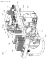
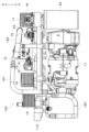
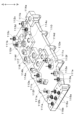
- FIG. 1 is an overall configuration diagram showing a vehicle air conditioner according to a first embodiment. It is a perspective view showing a compressor module of a 1st embodiment. It is a front view showing a compressor module of a 1st embodiment. It is a perspective view showing a channel plate of a compressor module of a 1st embodiment.
- FIG. 2 is a side view schematically showing the compressor module of the first embodiment. It is a sectional view showing typically a compressor module of a 2nd embodiment. It is a sectional view showing typically a channel plate of a compressor module of a 3rd embodiment.
- the compressor module of this embodiment will be explained using FIGS. 1 to 5.
- the compressor module of this embodiment is applied to a vehicle air conditioner 1 mounted on an electric vehicle.
- An electric vehicle is a vehicle that obtains driving force for driving from an electric motor.
- the vehicle air conditioner 1 is a heat pump cycle device that air-conditions a vehicle interior, which is a space to be air-conditioned, and adjusts the temperature of in-vehicle equipment. Therefore, the vehicle air conditioner 1 can be called an air conditioner with a vehicle-mounted equipment temperature adjustment function, or a vehicle-mounted equipment temperature adjustment device with an air-conditioning function.
- the vehicle air conditioner 1 specifically adjusts the temperature of a battery (not shown) as an in-vehicle device.
- a battery is a secondary battery that stores power to be supplied to a plurality of in-vehicle devices that operate on electricity.
- a battery is an assembled battery formed by electrically connecting a plurality of stacked battery cells in series or parallel.
- the battery cell of this embodiment is a lithium ion battery.
- Batteries generate heat during operation i.e., when charging and discharging. Batteries have the characteristic that their output tends to decrease when the temperature falls, and their deterioration tends to progress when the temperature rises. Therefore, the temperature of the battery needs to be maintained within an appropriate temperature range (in this embodiment, 15° C. or higher and 55° C. or lower). Therefore, in the electric vehicle of this embodiment, the temperature of the battery is adjusted using the vehicle air conditioner 1.
- the vehicle air conditioner 1 includes a heat pump cycle 10, a high temperature heat medium circuit 30, a first low temperature heat medium circuit 40, a second low temperature heat medium circuit 50, an indoor air conditioning unit (not shown), a control device (not shown), etc. It is equipped with
- the heat pump cycle 10 is a vapor compression refrigeration cycle device that adjusts the temperature of the high temperature heat medium circulating in the high temperature heat medium circuit 30 and the low temperature heat medium circulating in the first low temperature heat medium circuit 40 and the second low temperature heat medium circuit 50. It is.
- the heat pump cycle 10 is configured to be able to switch refrigerant circuits according to various operation modes for air conditioning the vehicle interior and cooling vehicle equipment.
- the heat pump cycle 10 includes a compressor 11, a condenser 12, an intermediate pressure expansion valve 13, a gas-liquid separator 14, an expansion valve 15 for cooling, an expansion valve 16 for cooling, a hot gas flow rate adjustment valve 17, a chiller 18 for air conditioning, and a cooling It has a chiller 19, an accumulator 20, an intermediate pressure on-off valve 21, a bypass on-off valve 22, etc.
- the heat pump cycle 10 uses an HFO-based refrigerant (specifically, R1234yf) as the refrigerant.
- the heat pump cycle 10 constitutes a subcritical refrigeration cycle in which the pressure of the high-pressure side refrigerant does not exceed the critical pressure of the refrigerant.
- Refrigerating machine oil for lubricating the compressor 11 is mixed in the refrigerant.
- Refrigerating machine oil is PAG oil that is compatible with liquid phase refrigerant. A portion of the refrigeration oil circulates through the cycle along with the refrigerant.
- the compressor 11 sucks in refrigerant, compresses it, and discharges it.
- the compressor 11 is an electric compressor that uses an electric motor to drive a fixed capacity type compression mechanism with a fixed discharge capacity.
- the rotation speed (i.e., refrigerant discharge capacity) of the compressor 11 is controlled by a control signal output from a control device.
- the compressor 11 is a two-stage boost type electric compressor.
- the compressor 11, which is a two-stage boost type electric compressor, has two compression mechanisms, a low-stage compression mechanism and a high-stage compression mechanism, and both compression mechanisms inside a housing that forms its outer shell. It houses an electric motor that drives the rotation.
- the housing of the compressor 11 is provided with a suction port 11a, an intermediate pressure port 11b, and a discharge port 11c.
- the suction port 11a is a suction port for sucking low-pressure refrigerant into the low-stage compression mechanism from the outside of the housing.
- the discharge port 11c is a discharge port that discharges the high-pressure refrigerant discharged from the high-stage compression mechanism to the outside of the housing.
- the intermediate pressure port 11b is an intermediate pressure suction port for allowing intermediate pressure refrigerant to flow into the housing from the outside of the housing to join the refrigerant in the compression process from low pressure to high pressure. That is, the intermediate pressure port 11b is connected to the discharge port side of the low stage compression mechanism and the suction port side of the high stage compression mechanism inside the housing.
- the compressor 11 of this embodiment accommodates two compression mechanisms in one housing, the type of the two-stage boost compressor is not limited to this.
- the compressor 11 of this embodiment has one fixed capacity type refrigerant inside the housing, if it is possible to let the intermediate pressure refrigerant flow in from the intermediate pressure port 11b and join the refrigerant in the compression process from low pressure to high pressure.
- the electric compressor may include a compression mechanism and an electric motor that rotationally drives the compression mechanism.
- the compressor 11 of this embodiment has two compressors connected in series, the suction port of the low-stage compressor disposed on the low-stage side being the suction port 11a, and the high-stage compressor disposed on the high-stage side serving as a suction port 11a.
- the discharge port of the side compressor is set as a discharge port 11c, and an intermediate pressure port 11b is provided at the connection part connecting the discharge port of the low stage compressor and the suction port of the high stage compressor.
- the electric compressor may be an electric compressor in which both the high-stage compressor and the high-stage compressor constitute one two-stage step-up compressor.
- the condenser 12 is a heat exchange unit that exchanges heat between the refrigerant discharged from the compressor 11 and the high temperature heat medium of the high temperature heat medium circuit 30.
- the heat of the refrigerant discharged from the compressor 11 is radiated to the high-temperature heat medium, which is the fluid to be heated, thereby heating the high-temperature heat medium.
- a high temperature heat medium pump, a heater core, a radiator, a switching valve, and an electric heater are arranged in the high temperature heat medium circuit 30.
- the high temperature heat medium pump sucks in the high temperature heat medium of the high temperature heat medium circuit 30 and discharges it.
- the heater core is a heat exchanger that heats the air by exchanging heat between the high temperature heat medium of the high temperature heat medium circuit 30 and the air blown into the vehicle interior.
- the high temperature heat medium of the high temperature heat medium circuit 30 is, for example, an ethylene glycol aqueous solution.
- the radiator is a heat exchanger that heats the air by exchanging heat between the high temperature heat medium of the high temperature heat medium circuit 30 and the outside air.
- the switching valve switches between a state where the high temperature heat medium of the high temperature heat medium circuit 30 flows through the heater core and a state where the high temperature heat medium flows through the radiator.
- the electric heater is a heat medium heater that generates heat when supplied with electric power and heats the high temperature heat medium of the high temperature heat medium circuit 30.
- the intermediate pressure expansion valve 13 is a pressure reducing part that reduces the pressure of the refrigerant flowing out from the condenser 12 and adjusts the flow rate of the refrigerant flowing downstream.
- the operation of the intermediate pressure expansion valve 13 is controlled by a control signal (specifically, a control pulse) output from a control device. Therefore, the intermediate pressure expansion valve 13 is an electrical device.
- the intermediate pressure expansion valve 13 has a fully open function of fully opening the throttle passage to function as a mere refrigerant flow path without exerting much of a flow rate adjustment action or a refrigerant pressure reduction action.
- the gas-liquid separator 14 has a refrigerant inlet 14a, a gas-phase refrigerant outlet 14b, and a liquid-phase refrigerant outlet 14c.
- the refrigerant flowing out from the intermediate pressure expansion valve 13 flows into the refrigerant inlet 14a.
- the gas-liquid separator 14 separates the gas and liquid of the refrigerant flowing in from the refrigerant inlet 14a, causes the separated gas-phase refrigerant to flow out from the vapor-phase refrigerant outlet 14b, and causes the separated liquid-phase refrigerant to flow out from the liquid-phase refrigerant outlet 14c. .
- the cooling expansion valve 15 and the cooling expansion valve 16 are pressure reducing units that reduce the pressure of the liquid phase refrigerant flowing out from the liquid phase refrigerant outlet 14c of the gas-liquid separator 14, and adjust the flow rate of the refrigerant flowing downstream. .
- the basic configuration of the cooling expansion valve 15 and the cooling expansion valve 16 is the same as that of the intermediate pressure expansion valve 13. Therefore, the cooling expansion valve 15 and the cooling expansion valve 16 are electrical devices.
- the cooling expansion valve 15 and the cooling expansion valve 16 have a fully closing function of closing the refrigerant flow path by fully closing the throttle passage.
- the hot gas flow rate adjustment valve 17 is an electric variable throttle mechanism that reduces the pressure of the refrigerant flowing through the hot gas flow path 23 and adjusts the flow rate of the refrigerant flowing downstream.
- the basic configuration of the hot gas flow rate adjustment valve 17 is the same as that of the intermediate pressure expansion valve 13. Therefore, the hot gas flow rate regulating valve 17 is an electrical device.
- the hot gas flow rate adjustment valve 17 has a fully closing function of closing the refrigerant flow path by fully closing the throttle passage.
- the air conditioning chiller 18 is a heat exchange unit that exchanges heat between the low-pressure refrigerant whose pressure has been reduced by the cooling expansion valve 15 and the low-temperature heat medium of the first low-temperature heat medium circuit 40.
- the air conditioning chiller 18 is an evaporator that cools the low-temperature heat medium by evaporating the low-pressure side refrigerant and exhibiting an endothermic action.
- a first low temperature heat medium pump and a cooler core are arranged in the first low temperature heat medium circuit 40.
- the first low-temperature heat medium pump sucks in and discharges the low-temperature heat medium of the first low-temperature heat medium circuit 40 .
- the cooler core is a heat exchanger that cools the air by exchanging heat between the low temperature heat medium of the first low temperature heat medium circuit 40 and the air blown into the vehicle interior.
- the low temperature heat medium of the first low temperature heat medium circuit 40 is, for example, an ethylene glycol aqueous solution.
- the cooling chiller 19 is a heat exchange unit that exchanges heat between the low-pressure refrigerant whose pressure has been reduced by the cooling expansion valve 16 and the low-temperature heat medium of the second low-temperature heat medium circuit 50.
- the cooling chiller 19 is an evaporator that cools the low-temperature heat medium by evaporating the low-pressure side refrigerant and exerting an endothermic action.
- a second low temperature heat medium pump and a battery are arranged in the second low temperature heat medium circuit 50.
- the second low-temperature heat medium pump takes in and discharges the low-temperature heat medium of the second low-temperature heat medium circuit 50.
- the low-temperature heat medium of the second low-temperature heat medium circuit 50 flows through the heat medium flow path in the battery, and the low-temperature heat medium absorbs heat from the battery, thereby cooling the battery.
- the low temperature heat medium of the second low temperature heat medium circuit 50 is, for example, an ethylene glycol aqueous solution.
- the accumulator 20 is a low-pressure side gas-liquid separator that separates the gas-liquid of the refrigerant that has flowed into it and stores the excess liquid-phase refrigerant in the cycle.
- the accumulator 20 is a liquid storage section.
- the intermediate pressure on/off valve 21 is a solenoid valve that opens and closes the intermediate pressure passage 24.
- the intermediate pressure on/off valve 21 is a solenoid valve whose opening/closing operation is controlled by a control voltage output from a control device. Therefore, the intermediate pressure on-off valve 21 is an electrical device.
- the intermediate pressure flow path 24 is connected to the gas phase refrigerant outlet 14b of the gas-liquid separator 14 and the intermediate pressure port 11b of the compressor 11.
- the bypass on-off valve 22 is a solenoid valve that opens and closes the bypass flow path 25.
- the bypass opening/closing valve 22 is an electromagnetic valve whose opening/closing operation is controlled by a control voltage output from a control device. Therefore, the bypass on-off valve 22 is an electrical device.
- the heat pump cycle 10 has a first branch part 26a, a second branch part 26b, and a third branch part 26c that branch the flow of the refrigerant.
- the heat pump cycle 10 has a first merging section 27a, a second merging section 27b, and a third merging section 27c that merge the flows of refrigerant.
- the first branch part 26a branches the flow of refrigerant discharged from the compressor 11 into the condenser 12 side and the hot gas flow path 23 side.
- the second branch part 26b branches the flow of the liquid phase refrigerant flowing out from the liquid phase refrigerant outlet 14c of the gas-liquid separator 14 into the cooling expansion valve 15 side and the cooling expansion valve 16 side.
- the third branching portion 26c branches the flow of the refrigerant that merged at the first merging portion 27a into the accumulator 20 side and the bypass flow path 25 side.
- the first merging portion 27a merges the flow of refrigerant flowing out from the hot gas flow path 23 and the flow of refrigerant evaporated in the air conditioning chiller 18.
- the second merging portion 27b merges the flow of refrigerant flowing out from the bypass channel 25 and the flow of gas phase refrigerant flowing out from the accumulator 20.
- the third merging section 27c merges the flow of the refrigerant evaporated in the cooling chiller 19 and the flow of the refrigerant that merged at the second merging section 27b.
- a suction refrigerant flow path 28 is connected between the refrigerant outlet of the third merging portion 27c and the suction port 11a of the compressor 11.
- the indoor air conditioning unit (not shown) is a unit that integrates multiple components in order to blow out air adjusted to an appropriate temperature for air conditioning the vehicle interior to appropriate locations within the vehicle interior.
- the indoor air conditioning unit is located inside the instrument panel at the very front of the vehicle interior.
- the indoor air conditioning unit is formed by accommodating an indoor blower (not shown), a cooler core, a heater core, etc. in an air conditioning case (not shown) that forms an air passage.
- the heat pump cycle 10 has a refrigerant pressure sensor group and a refrigerant temperature sensor group.
- the refrigerant pressure sensor group includes an intake refrigerant pressure sensor 61, a discharge refrigerant pressure sensor 62, and the like.
- the suction refrigerant pressure sensor 61 is a refrigerant pressure sensor that detects the pressure of refrigerant sucked into the suction port 11a of the compressor 11.
- the discharge refrigerant pressure sensor 62 is a refrigerant pressure sensor that detects the pressure of refrigerant discharged from the discharge port 11c of the compressor 11.
- the refrigerant temperature sensor group includes a condensed refrigerant temperature sensor 63, an evaporative refrigerant temperature sensor 64, and the like.
- the condensed refrigerant temperature sensor 63 is a refrigerant temperature sensor that detects the temperature of the refrigerant flowing out from the condenser 12.
- the evaporative refrigerant temperature sensor 64 is a refrigerant temperature sensor that detects the temperature of the refrigerant flowing out from the cooling chiller 19.
- the control device includes a well-known microcomputer including a CPU, ROM, RAM, etc., and its peripheral circuits.
- the control device performs various calculations and processes based on a control program stored in the ROM. Then, the control device controls the operation of various controlled devices connected to the output side based on the calculation and processing results.
- An operation panel (not shown) is connected to the input side of the control device.
- the operation panel is located near the instrument panel at the front of the vehicle interior, and is equipped with various operation switches. Operation signals from various operation switches provided on the operation panel are input to the control device.
- the various operation switches provided on the operation panel include an auto switch, an air conditioner switch, an air volume setting switch, a temperature setting switch, etc.
- the auto switch is an operation switch that sets or cancels automatic control operation of the vehicle air conditioner 1.
- the air conditioner switch is an operation switch that requires the cooler core to cool the air.
- the air volume setting switch is an operation switch for manually setting the volume of air blown into the vehicle interior (that is, the volume of air blown by the indoor blower).
- the temperature setting switch is an operation switch that sets the temperature within the vehicle interior.
- the compressor module 100 shown in FIGS. 2 and 3 is a component that integrates a plurality of components that mainly constitute the heat pump cycle 10.
- the vertical arrows in FIGS. 2 and 3 indicate the vertical direction of the electric vehicle in which the compressor module 100 is mounted.
- a compressor 11 among the components of the heat pump cycle 10, a compressor 11, a condenser 12, an intermediate pressure expansion valve 13, a gas-liquid separator 14, an expansion valve 15 for cooling, and an expansion valve 16 for cooling.
- a hot gas flow rate adjustment valve 17 an air conditioning chiller 18, a cooling chiller 19, an accumulator 20, an intermediate pressure on/off valve 21, a bypass on/off valve 22, etc. are integrated.
- the channel plate 110 is a mounting member for mounting a plurality of component devices.
- the flow path plate 110 is formed of metal (aluminum alloy in this embodiment) by casting.
- the channel plate 110 is formed into a plate shape extending in the horizontal direction.
- a condenser 12 On the upper surface of the flow path plate 110, a condenser 12, an intermediate pressure expansion valve 13, a gas-liquid separator 14, an expansion valve 15 for cooling, an expansion valve 16 for cooling, a hot gas flow rate adjustment valve 17, a chiller 18 for air conditioning, and a cooling A chiller 19 and a bypass on-off valve 22 are fixed.
- the intermediate pressure on-off valve 21 is integrated with the gas-liquid separator 14.
- a compressor 11 and an accumulator 20 are fixed to the lower surface of the flow path plate 110.
- a bracket (not shown) is attached to the side surface of the channel plate 110.
- the bracket is a member used to fix the compressor module 100 to the vehicle. For example, the bracket extends downward so as to straddle the compressor 11 and the accumulator 20.
- the flow path plate 110 has a plurality of refrigerant flow paths through which the refrigerant of the heat pump cycle 10 flows, a plurality of heat medium flow paths through which the high temperature heat medium of the high temperature heat medium circuit 30 flows, and the first low temperature heat medium circuit 40. and a flow path forming member in which a plurality of heat medium flow paths through which the low temperature heat medium of the second low temperature heat medium circuit 50 flows are formed.
- the first branch part 26a, the second branch part 26b, the third branch part 26c, the first merging part 27a, the second merging part 27b, and the third merging part 27c are formed inside the channel plate 110.
- the upper surface of the flow path plate 110 includes a plurality of seat parts 111a for fixing the condenser 12, a plurality of seat parts 111b for fixing the air conditioning chiller 18, and a cooling chiller 19.
- a plurality of seat surface portions 111c are formed for fixing.
- the vertical arrows in FIG. 4 indicate the vertical direction of the electric vehicle in which the compressor module 100 is mounted.
- an outlet 112a for refrigerant to the condenser 12 On the upper surface of the flow path plate 110, there are an outlet 112a for refrigerant to the condenser 12, an inlet 112b for the refrigerant from the condenser 12, an outlet 112c for the refrigerant to the air conditioning chiller 18, and an inlet 112d for the refrigerant from the air conditioning chiller 18. , an outlet 112e for the refrigerant to the cooling chiller 19, and an inlet 112f for the refrigerant from the cooling chiller 19.
- an outlet 113a for the high temperature heat medium to the condenser 12 On the upper surface of the flow path plate 110, there are an outlet 113a for the high temperature heat medium to the condenser 12, an outlet 113c for the low temperature heat medium to the air conditioning chiller 18, an inlet 113d for the low temperature heat medium from the air conditioning chiller 18, and a cooling chiller.
- An outlet 113e for the low temperature heat medium to the cooling chiller 19 and an inlet 113f for the low temperature heat medium from the cooling chiller 19 are formed.
- the upper surface of the flow path plate 110 has a mounting hole 114a to which the intermediate pressure expansion valve 13 is mounted, a mounting hole 114b to which the gas-liquid separator 14 is mounted, a mounting hole 114c to which the cooling expansion valve 15 is mounted, and a cooling expansion valve 16.
- a mounting hole 114d to which the hot gas flow rate regulating valve 17 is mounted, a mounting hole 114e to which the hot gas flow rate adjustment valve 17 is mounted, and a mounting hole 114f to which the bypass opening/closing valve 22 is mounted are formed.
- a high temperature heat medium inlet 115a into which the high temperature heat medium flows, a low temperature heat medium inlet 115b into which the low temperature heat medium flows, and a high temperature heat medium outlet 115c into which the low temperature heat medium flows out are formed on the upper surface of the channel plate 110. .
- a suction refrigerant outlet 116 is formed on the upper surface of the flow path plate 110.
- the suction refrigerant outlet 116 is a refrigerant outlet of the third merging section 27c.
- a discharge refrigerant pipe 120, an intermediate pressure refrigerant pipe 121, and a suction refrigerant pipe 122 are arranged outside the flow path plate 110.
- the vertical arrows in FIG. 5 indicate the vertical direction of the electric vehicle in which the compressor module 100 is mounted.
- the discharge refrigerant pipe 120 is a flow path forming member that forms the refrigerant flow path 29 between the discharge port 11c of the compressor 11 and the first branch portion 26a shown in FIG.
- the intermediate pressure refrigerant pipe 121 is a flow path forming member that forms a flow path between the intermediate pressure on-off valve 21 and the intermediate pressure port 11b of the compressor 11 in the intermediate pressure flow path 24 shown in FIG.
- the suction refrigerant pipe 122 is a flow path forming member that forms the suction refrigerant flow path 28.
- the suction refrigerant pipe 122 rises upward from the suction refrigerant outlet 116 that opens on the upper surface of the flow path plate 110, and then hangs down toward the through hole 117 of the flow path plate 110. Furthermore, it passes through the through hole 117 of the flow path plate 110 and hangs below the flow path plate 110, and is connected to the suction port 11a of the compressor 11.
- the operation of the vehicle air conditioner 1 of this embodiment with the above configuration will be explained.
- various driving modes are switched in order to air condition the vehicle interior and adjust the temperature of the battery.
- Switching of the operation mode is performed by executing a control program stored in the control device in advance.
- the operation mode is switched by the control device controlling the operation of the intermediate pressure expansion valve 13, the cooling expansion valve 15, the cooling expansion valve 16, the hot gas flow rate adjustment valve 17, the intermediate pressure on-off valve 21, and the bypass on-off valve 22. .
- Various operation modes of the vehicle air conditioner 1 include, for example, independent cooling mode, cooling/cooling mode, independent dehumidifying/heating mode, cooling/dehumidifying/heating mode, independent cooling mode, etc.
- the independent cooling mode is an operation mode in which the interior of the vehicle is cooled by blowing air cooled by the cooler core into the vehicle interior.
- the cooling cooling mode is an operation mode in which the interior of the vehicle is cooled by blowing air cooled by the cooler core into the vehicle interior, and the battery is also cooled by the low-temperature heat medium cooled by the cooling chiller 19.
- the independent dehumidification/heating mode is an operation mode in which the air cooled by the cooler core is heated by the heater core and blown out into the passenger compartment, thereby dehumidifying and heating the vehicle interior.
- the air cooled by the cooler core is heated by the heater core and blown into the vehicle interior to dehumidify and heat the vehicle interior, and at the same time, the battery is cooled by the low-temperature heat medium cooled by the cooling chiller 19. It is in driving mode.
- the independent cooling mode is an operation mode in which the battery is cooled by a low-temperature heat medium cooled by the cooling chiller 19.
- the hot gas flow rate adjustment valve 17 By setting the hot gas flow rate adjustment valve 17 to the throttle state, the low enthalpy refrigerant flowing out from at least one of the air conditioning chiller 18 and the cooling chiller 19 and the high enthalpy refrigerant flowing out from the hot gas flow path 23 are separated. The mixture is sucked into the compressor 11.
- the control device controls the throttle opening of the hot gas flow rate adjustment valve 17 so that the degree of superheat of the refrigerant sucked into the compressor 11 approaches the target degree of superheat, thereby controlling the state of the refrigerant sucked into the compressor 11. It can be a gas phase refrigerant with a degree of superheat.
- the intermediate pressure refrigerant in the gas phase that has passed through the intermediate pressure expansion valve 13 and the gas-liquid separator 14 can flow into the intermediate pressure port 11b of the compressor 11. Therefore, the intermediate-pressure refrigerant in the gas phase that has passed through the intermediate-pressure expansion valve 13 and the gas-liquid separator 14 can be combined with the refrigerant in the pressure increasing process sucked from the suction port 11a in the compressor 11. That is, the heat pump cycle 10 can constitute a gas injection cycle.
- bypass on-off valve 22 By opening the bypass on-off valve 22, a part of the refrigerant that has merged at the first merging portion 27a can bypass the accumulator 20 and flow into the bypass channel 25. Thereby, the pressure loss of the refrigerant in the accumulator 20 can be reduced and the performance of the heat pump cycle 10 can be improved.
- the refrigerant flow path of the heat pump cycle 10 has a region where the liquid phase refrigerant flows and a region where the gas phase refrigerant flows.
- the gas phase refrigerant whose pressure has been reduced by the hot gas flow rate adjustment valve 17, the gas phase refrigerant evaporated by the air conditioning chiller 18, and the gas phase refrigerant evaporated by the cooling chiller 19 are transferred from the third confluence section 27c to the suction refrigerant pipe 122.
- the refrigerant is sucked into the suction port 11a of the compressor 11 through the suction refrigerant flow path 28.
- the heat pump cycle 10 stops operating (in other words, when the compressor 11 stops), the high temperature gas phase refrigerant in the refrigerant flow path, the gas phase refrigerant in the air conditioning chiller 18, and the air in the cooling chiller 19
- the phase refrigerant radiates heat to the surroundings and condenses and liquefies as time passes.
- the refrigerant that is condensed and liquefied during the operation stop of the heat pump cycle 10 flows down in the refrigerant flow path of the heat pump cycle 10 from the higher side to the lower side due to the action of gravity. If the condensed and liquefied refrigerant flows down from the flow path plate 110 to the suction port 11a of the compressor 11 while the heat pump cycle 10 is stopped, when the heat pump cycle 10 is restarted (in other words, the compressor is restarted). When the compressor 11 is in operation), the liquid phase refrigerant accumulated in the compressor 11 may be compressed and the durability of the compressor 11 may be reduced.
- the suction refrigerant pipe 122 rises upward from the suction refrigerant outlet 116 of the flow path plate 110, the refrigerant condensed and liquefied during the operation stop of the heat pump cycle 10 is drawn into the compressor 11 by gravity. It is possible to suppress the water from flowing down to the port 11a. Therefore, it is possible to suppress liquid compression from occurring in the compressor 11 when the compressor is restarted.
- the compressor 11 is disposed on the lower side of the flow path plate 110, and the suction refrigerant flow path 28 has a rising portion 28a that rises upward toward the compressor 11 side.
- the rising portion 28a prevents the liquefied refrigerant from flowing down from the flow path plate 110 to the compressor 11 due to gravity. can do. Therefore, it is possible to suppress liquid compression from occurring when the compressor 11 is restarted.
- the accumulator 20 is arranged below the channel plate 110. According to this, when the compressor 11 is stopped, the liquefied refrigerant flows down to the accumulator 20 due to gravity and tends to accumulate in the accumulator 20. Therefore, it is possible to suppress the liquefied refrigerant from flowing down from the flow path plate 110 to the compressor 11 due to gravity, so that it is possible to suppress liquid compression from occurring when the compressor 11 is restarted.
- the air conditioning chiller 18 and the cooling chiller 19 are arranged above the channel plate 110. Thereby, the air conditioning chiller 18, the cooling chiller 19, and the compressor 11 can be efficiently arranged separately on both the upper and lower sides of the channel plate 110.
- the suction refrigerant pipe 122 rises upward from the suction refrigerant outlet 116 of the flow path plate 110, thereby forming the rising portion 28a. Thereby, the rising portion 28a can be easily formed.
- the flow path plate 110 is a plate-shaped member that extends in the horizontal direction, and the compressor 11 is fixed to the lower surface of the flow path plate 110. Thereby, the compressor 11 and other components of the heat pump cycle 10 can be efficiently arranged on the flow path plate 110.
- the suction refrigerant flow path 28 is formed by the suction refrigerant pipe 122, but in this embodiment, the suction refrigerant flow path 28 is formed inside the flow path plate 110, as shown in FIG. A rising portion 28a of the suction refrigerant flow path 28 is formed inside the flow path plate 110.
- the vertical arrows in FIG. 6 indicate the vertical direction of the electric vehicle in which the compressor module 100 is mounted.
- the suction refrigerant outlet 116 is formed on the lower surface of the flow path plate 110 and is directly connected to the suction port 11a of the compressor 11.
- the rising portion 28a of the suction refrigerant flow path 28 can prevent the refrigerant that has condensed and liquefied during operation stoppage from flowing down to the compressor 11, so that the liquid can be compressed when the compressor 11 restarts. can be suppressed from occurring.
- the rising portion 28a is formed inside the flow path plate 110, the rising portion 28a can be formed while suppressing an increase in the size of the compressor module 100 as much as possible.
- FIG. 7 a liquid reservoir 119 recessed downward is formed in the refrigerant flow path 118 inside the flow path plate 110.
- the vertical arrows in FIG. 7 indicate the vertical direction of the electric vehicle in which the compressor module 100 is mounted.
- the liquid reservoir 119 collects refrigerant that has condensed and liquefied during the shutdown. Therefore, it is possible to suppress the refrigerant that has condensed and liquefied during the shutdown from flowing into the compressor 11 when the compressor 11 is restarted.
- the accumulator 20 is arranged below the flow path plate 110 so that the refrigerant condensed during the operation stop is likely to accumulate in the accumulator 20. This is because the refrigerant that has condensed and liquefied during the operation stop is likely to flow down from the flow path plate 110 to the accumulator 20 due to gravity.
- the liquid reservoir 119 is formed so that the liquid phase refrigerant can be stored inside the flow path plate 110. Or it can be placed above.
- the air conditioning chiller 18 is arranged above the channel plate 110 so that the refrigerant condensed and liquefied by the air conditioning chiller 18 during operation stoppage easily accumulates in the accumulator 20, and the accumulator 20 is arranged above the channel plate 110. 110.
- the refrigerant that is condensed and liquefied in the air conditioning chiller 18 during operation stoppage tends to flow down to the accumulator 20 due to gravity. This suppresses the refrigerant that has been condensed and liquefied in the air conditioning chiller 18 during the shutdown period from flowing into the compressor 11 through the bypass channel 25 when the compressor 11 is restarted.
- the liquid reservoir 119 of the present embodiment is formed in the bypass flow path 25, the refrigerant that is condensed and liquefied in the air conditioning chiller 18 during operation stop will pass through the bypass flow path 25 to the compressor when the compressor 11 is restarted. 11 , it becomes possible to arrange the air conditioning chiller 18 below the channel plate 110 .
- a liquid reservoir 119 may be formed in the suction refrigerant flow path 28.
- the flow path plate 110 has a liquid reservoir 119 in which the refrigerant flow path 118 is recessed downward so that the liquid phase refrigerant accumulates therein.
- the vehicle air conditioner 1 has been described as a heat pump cycle device to which a compressor module is applied, but the heat pump cycle device to which a compressor module is applied is not limited to a vehicle air conditioner.
- it may be a stationary air conditioner with a temperature adjustment function that adjusts the temperature of a temperature-adjusted object (for example, a computer, a computer server device, or other electrical equipment) while air-conditioning the room.
- a temperature-adjusted object for example, a computer, a computer server device, or other electrical equipment
- the temperature of a battery is adjusted as an in-vehicle device whose temperature is to be adjusted, but the in-vehicle device is not limited to a battery.
- the temperature of an inverter, PCU, transaxle, ADAS control device, etc. may be adjusted.
- the inverter supplies power to the motor generator, etc.
- the PCU is a power control unit that performs power transformation and power distribution.
- a transaxle is a power transmission mechanism that integrates a transmission, differential gear, etc.
- the control device for ADAS is a control device for an advanced driving support system.
- the specific configuration of the compressor module 100 is not limited to the configuration disclosed in the above embodiment.
- each component of the heat pump cycle 10 that is integrated into the compressor module 100 is not limited to the components disclosed in the above-described embodiments. As long as the compressor 11, at least one evaporator, and the accumulator 20 are integrated into at least the flow path plate 110, the other components may or may not be integrated. good.
- the specific configuration of the heat pump cycle device to which the compressor module is applied is not limited to the configuration disclosed in the above embodiment.
- the refrigerant of the heat pump cycle 10 is not limited to R1234yf.
- R134a, R600a, R410A, R404A, R32, R407C, etc. may be employed.
- a mixed refrigerant made by mixing a plurality of these refrigerants may be used.
- the high temperature heat medium of the high temperature heat medium circuit 30 and the low temperature heat medium of the first low temperature heat medium circuit 40 and the second low temperature heat medium circuit 50 are not limited to an ethylene glycol aqueous solution.
- the high-temperature heat medium and the low-temperature heat medium dimethylpolysiloxane, a solution containing nanofluid, etc., an antifreeze solution, an aqueous liquid refrigerant containing alcohol, etc., a liquid medium containing oil, etc. may be employed.
- the operating mode of the heat pump cycle 10 to which the compressor module is applied is not limited to the mode disclosed in the above embodiment.
- a slope or a step may be provided in the refrigerant flow path inside the flow path plate 110 so that the refrigerant flow path inside the flow path plate 110 descends downward toward the accumulator 20.
- the refrigerant that has condensed during the stoppage of operation naturally flows down due to gravity and is likely to accumulate in the accumulator 20, so that it is possible to suppress the refrigerant from flowing into the compressor 11 when the operation is restarted.
- the flow path plate 110 is formed by casting, but the flow path plate 110 may be formed by bonding metal plates together or combining cutting blocks.
- an evaporator (18, 19) for evaporating refrigerant in a vapor compression refrigeration cycle (Item 1) an evaporator (18, 19) for evaporating refrigerant in a vapor compression refrigeration cycle; a liquid storage section (20) that stores the refrigerant in a liquid phase; a compressor (11) that sucks and compresses refrigerant; A flow path forming member (110) to which the evaporator, the liquid storage section, and the compressor are attached and forms at least a part of the refrigerant flow path, The compressor is disposed below the flow path forming member, Among the refrigerant flow paths, the suction refrigerant flow path (28) through which the gas phase refrigerant sucked into the compressor flows has a rising portion (28a) that rises upward toward the compressor. compressor module.
- suction refrigerant pipe (122) that is a piping member that forms a passage for the refrigerant from the flow path forming member to the compressor in the suction refrigerant flow path;
- a suction refrigerant outlet (116) from which the refrigerant flows out and to which the suction refrigerant pipe is connected is formed in the flow path forming member;
- the compressor module according to any one of items 1 to 3, wherein the rising portion (28a) is formed by the suction refrigerant pipe rising upward from the suction refrigerant outlet.
- the flow path forming member is a plate-shaped member that spreads in the horizontal direction,
- the compressor module according to any one of items 1 to 4, wherein the compressor is fixed to a lower surface of the flow path forming member.
- the flow path forming member has a liquid reservoir portion (119) in which the flow path of the refrigerant is depressed downward so that the refrigerant in a liquid phase accumulates therein. compressor module.
- (Item 7) The compressor module according to any one of items 1 to 6, wherein the rising portion is formed inside the flow path forming member.
Landscapes
- Engineering & Computer Science (AREA)
- Physics & Mathematics (AREA)
- Thermal Sciences (AREA)
- Mechanical Engineering (AREA)
- General Engineering & Computer Science (AREA)
- Air-Conditioning For Vehicles (AREA)
Abstract
Description
図1~図5を用いて、本実施形態の圧縮機モジュールを説明する。本実施形態の圧縮機モジュールは、電気自動車に搭載された車両用空調装置1に適用されている。電気自動車は、走行用の駆動力を電動モータから得る車両である。車両用空調装置1は、空調対象空間である車室内の空調、および車載機器の温度調整を行うヒートポンプサイクル装置である。従って、車両用空調装置1は、車載機器温度調整機能付きの空調装置、あるいは、空調機能付きの車載機器温度調整装置と呼ぶことができる。
上記第1実施形態では、吸入冷媒流路28が吸入冷媒配管122で形成されているが、本実施形態では、図6に示すように、吸入冷媒流路28が流路プレート110の内部に形成されており、流路プレート110の内部に吸入冷媒流路28の立ち上がり部28aが形成されている。図6の上下方向の矢印は、圧縮機モジュール100が搭載された電気自動車の上下方向を示している。
本実施形態では、図7に示すように、流路プレート110の内部の冷媒流路118に、下方側に窪んだ液溜め部119が形成されている。図7の上下方向の矢印は、圧縮機モジュール100が搭載された電気自動車の上下方向を示している。
蒸気圧縮式冷凍サイクルの冷媒を蒸発させる蒸発器(18、19)と、
液相の前記冷媒を蓄える貯液部(20)と、
冷媒を吸入して圧縮する圧縮機(11)と、
前記蒸発器、前記貯液部、前記圧縮機が取り付けられるとともに、前記冷媒の流路の少なくとも一部を形成する流路形成部材(110)とを備え、
前記圧縮機は、前記流路形成部材の下方側に配置されており、
前記冷媒の流路のうち、前記圧縮機に吸入される気相の前記冷媒が流れる吸入冷媒流路(28)は、前記圧縮機側に向かうにつれて上方側へ立ち上がる立ち上がり部(28a)を有している圧縮機モジュール。
前記貯液部は、前記流路形成部材の下方側に配置されている項目1に記載の圧縮機モジュール。
前記蒸発器は、前記流路形成部材の上方側に配置されている項目1または2に記載の圧縮機モジュール。
前記吸入冷媒流路のうち前記流路形成部材から前記圧縮機に至る前記冷媒の通路を形成する配管部材である吸入冷媒配管(122)を備え、
前記流路形成部材には、前記冷媒が流出し、前記吸入冷媒配管が接続される吸入冷媒出口(116)が形成されており、
前記吸入冷媒配管が前記吸入冷媒出口から上方に立ち上がっていることによって前記立ち上がり部(28a)が形成されている項目1ないし3のいずれか1つに記載の圧縮機モジュール。
前記流路形成部材は、水平方向に拡がる板状の部材であり、
前記圧縮機は、前記流路形成部材の下面に固定されている項目1ないし4のいずれか1つに記載の圧縮機モジュール。
前記流路形成部材は、液相の前記冷媒が溜まるように前記冷媒の流路を下方側に窪ませた液溜め部(119)を有している項目1ないし5のいずれか1つに記載の圧縮機モジュール。
前記立ち上がり部は、前記流路形成部材の内部に形成されている項目1ないし6のいずれか1つに記載の圧縮機モジュール。
Claims (7)
- 蒸気圧縮式冷凍サイクルの冷媒を蒸発させる蒸発器(18、19)と、
液相の前記冷媒を蓄える貯液部(20)と、
前記冷媒を吸入して圧縮する圧縮機(11)と、
前記蒸発器、前記貯液部、前記圧縮機が取り付けられるとともに、前記冷媒の流路の少なくとも一部を形成する流路形成部材(110)とを備え、
前記圧縮機は、前記流路形成部材の下方側に配置されており、
前記冷媒の流路のうち、前記圧縮機に吸入される気相の前記冷媒が流れる吸入冷媒流路(28)は、前記圧縮機側に向かうにつれて上方側へ立ち上がる立ち上がり部(28a)を有している圧縮機モジュール。 - 前記貯液部は、前記流路形成部材の下方側に配置されている請求項1に記載の圧縮機モジュール。
- 前記蒸発器は、前記流路形成部材の上方側に配置されている請求項1または2に記載の圧縮機モジュール。
- 前記吸入冷媒流路のうち前記流路形成部材から前記圧縮機に至る前記冷媒の通路を形成する配管部材である吸入冷媒配管(122)を備え、
前記流路形成部材には、前記冷媒が流出し、前記吸入冷媒配管が接続される吸入冷媒出口(116)が形成されており、
前記吸入冷媒配管が前記吸入冷媒出口から上方に立ち上がっていることによって前記立ち上がり部(28a)が形成されている請求項1または2に記載の圧縮機モジュール。 - 前記流路形成部材は、水平方向に拡がる板状の部材であり、
前記圧縮機は、前記流路形成部材の下面に固定されている請求項1または2に記載の圧縮機モジュール。 - 前記流路形成部材は、液相の前記冷媒が溜まるように前記冷媒の流路を下方側に窪ませた液溜め部(119)を有している請求項1または2に記載の圧縮機モジュール。
- 前記立ち上がり部は、前記流路形成部材の内部に形成されている請求項1または2に記載の圧縮機モジュール。
Priority Applications (2)
| Application Number | Priority Date | Filing Date | Title |
|---|---|---|---|
| CN202380038867.3A CN119213263A (zh) | 2022-05-13 | 2023-04-11 | 压缩机组件 |
| US18/924,377 US20250042225A1 (en) | 2022-05-13 | 2024-10-23 | Compressor module |
Applications Claiming Priority (2)
| Application Number | Priority Date | Filing Date | Title |
|---|---|---|---|
| JP2022079356A JP2025090878A (ja) | 2022-05-13 | 2022-05-13 | 圧縮機モジュール |
| JP2022-079356 | 2022-05-13 |
Related Child Applications (1)
| Application Number | Title | Priority Date | Filing Date |
|---|---|---|---|
| US18/924,377 Continuation US20250042225A1 (en) | 2022-05-13 | 2024-10-23 | Compressor module |
Publications (1)
| Publication Number | Publication Date |
|---|---|
| WO2023218834A1 true WO2023218834A1 (ja) | 2023-11-16 |
Family
ID=88730093
Family Applications (1)
| Application Number | Title | Priority Date | Filing Date |
|---|---|---|---|
| PCT/JP2023/014694 Ceased WO2023218834A1 (ja) | 2022-05-13 | 2023-04-11 | 圧縮機モジュール |
Country Status (4)
| Country | Link |
|---|---|
| US (1) | US20250042225A1 (ja) |
| JP (1) | JP2025090878A (ja) |
| CN (1) | CN119213263A (ja) |
| WO (1) | WO2023218834A1 (ja) |
Cited By (2)
| Publication number | Priority date | Publication date | Assignee | Title |
|---|---|---|---|---|
| WO2025146275A1 (fr) * | 2024-01-05 | 2025-07-10 | Valeo Systemes Thermiques | Assemblage pour un circuit de refrigerant |
| EP4725728A1 (en) * | 2024-10-11 | 2026-04-15 | Toyota Jidosha Kabushiki Kaisha | In-vehicle air conditioner and refrigerant module |
Citations (4)
| Publication number | Priority date | Publication date | Assignee | Title |
|---|---|---|---|---|
| JPH06323636A (ja) * | 1993-05-18 | 1994-11-25 | Daikin Ind Ltd | 冷凍装置 |
| JPH11132600A (ja) * | 1997-10-30 | 1999-05-21 | Mitsubishi Heavy Ind Ltd | 空気調和機 |
| JP2021047000A (ja) * | 2019-09-13 | 2021-03-25 | 株式会社デンソー | 接続モジュール |
| KR20210090004A (ko) * | 2020-01-09 | 2021-07-19 | 한온시스템 주식회사 | 차량용 히트펌프의 냉매 시스템 모듈 |
-
2022
- 2022-05-13 JP JP2022079356A patent/JP2025090878A/ja active Pending
-
2023
- 2023-04-11 CN CN202380038867.3A patent/CN119213263A/zh active Pending
- 2023-04-11 WO PCT/JP2023/014694 patent/WO2023218834A1/ja not_active Ceased
-
2024
- 2024-10-23 US US18/924,377 patent/US20250042225A1/en active Pending
Patent Citations (4)
| Publication number | Priority date | Publication date | Assignee | Title |
|---|---|---|---|---|
| JPH06323636A (ja) * | 1993-05-18 | 1994-11-25 | Daikin Ind Ltd | 冷凍装置 |
| JPH11132600A (ja) * | 1997-10-30 | 1999-05-21 | Mitsubishi Heavy Ind Ltd | 空気調和機 |
| JP2021047000A (ja) * | 2019-09-13 | 2021-03-25 | 株式会社デンソー | 接続モジュール |
| KR20210090004A (ko) * | 2020-01-09 | 2021-07-19 | 한온시스템 주식회사 | 차량용 히트펌프의 냉매 시스템 모듈 |
Cited By (3)
| Publication number | Priority date | Publication date | Assignee | Title |
|---|---|---|---|---|
| WO2025146275A1 (fr) * | 2024-01-05 | 2025-07-10 | Valeo Systemes Thermiques | Assemblage pour un circuit de refrigerant |
| FR3158146A1 (fr) * | 2024-01-05 | 2025-07-11 | Valeo Systemes Thermiques | Assemblage pour un circuit de réfrigérant |
| EP4725728A1 (en) * | 2024-10-11 | 2026-04-15 | Toyota Jidosha Kabushiki Kaisha | In-vehicle air conditioner and refrigerant module |
Also Published As
| Publication number | Publication date |
|---|---|
| JP2025090878A (ja) | 2025-06-18 |
| CN119213263A (zh) | 2024-12-27 |
| US20250042225A1 (en) | 2025-02-06 |
Similar Documents
| Publication | Publication Date | Title |
|---|---|---|
| JP7298580B2 (ja) | 冷凍サイクル装置 | |
| US12344075B2 (en) | Battery heating device for vehicle | |
| JP5799924B2 (ja) | 冷凍サイクル装置 | |
| JP6278132B2 (ja) | ヒートポンプサイクル | |
| JP5780166B2 (ja) | ヒートポンプサイクル | |
| WO2021100409A1 (ja) | 冷凍サイクル装置 | |
| JP7516761B2 (ja) | 冷凍サイクル装置 | |
| JP6760226B2 (ja) | 複合型熱交換器 | |
| JP2015101180A (ja) | ヒートポンプシステム | |
| JP2013217631A (ja) | 冷凍サイクル装置 | |
| JP2014228190A (ja) | 冷凍サイクル装置 | |
| JP2020040431A (ja) | 冷凍サイクル装置 | |
| JP2020104604A (ja) | 温度調整装置 | |
| JP7380199B2 (ja) | 冷凍サイクル装置 | |
| WO2020213537A1 (ja) | 冷凍サイクル装置 | |
| US20250042225A1 (en) | Compressor module | |
| JP2013203221A (ja) | 車両用の空調装置 | |
| JP6798441B2 (ja) | 冷凍サイクル装置 | |
| JP2023032097A (ja) | 圧縮機モジュール | |
| JP2018197613A (ja) | 冷凍サイクル装置 | |
| WO2016136288A1 (ja) | ヒートポンプサイクル | |
| CN111433538B (zh) | 制冷循环装置 | |
| CN118922673A (zh) | 制冷循环装置 | |
| JP6733625B2 (ja) | 冷凍サイクル装置 | |
| JP6769315B2 (ja) | 小型冷凍サイクル装置 |
Legal Events
| Date | Code | Title | Description |
|---|---|---|---|
| 121 | Ep: the epo has been informed by wipo that ep was designated in this application |
Ref document number: 23803316 Country of ref document: EP Kind code of ref document: A1 |
|
| WWE | Wipo information: entry into national phase |
Ref document number: 202380038867.3 Country of ref document: CN |
|
| NENP | Non-entry into the national phase |
Ref country code: DE |
|
| WWP | Wipo information: published in national office |
Ref document number: 202380038867.3 Country of ref document: CN |
|
| 122 | Ep: pct application non-entry in european phase |
Ref document number: 23803316 Country of ref document: EP Kind code of ref document: A1 |
|
| NENP | Non-entry into the national phase |
Ref country code: JP |