WO2023218769A1 - エアバッグ装置 - Google Patents
エアバッグ装置 Download PDFInfo
- Publication number
- WO2023218769A1 WO2023218769A1 PCT/JP2023/011736 JP2023011736W WO2023218769A1 WO 2023218769 A1 WO2023218769 A1 WO 2023218769A1 JP 2023011736 W JP2023011736 W JP 2023011736W WO 2023218769 A1 WO2023218769 A1 WO 2023218769A1
- Authority
- WO
- WIPO (PCT)
- Prior art keywords
- cushion
- chamber
- seat
- main chamber
- airbag device
- Prior art date
Links
- 238000009751 slip forming Methods 0.000 claims description 3
- 230000000452 restraining effect Effects 0.000 abstract description 2
- 238000012986 modification Methods 0.000 description 39
- 230000004048 modification Effects 0.000 description 39
- 239000004744 fabric Substances 0.000 description 10
- 239000000463 material Substances 0.000 description 5
- 238000003860 storage Methods 0.000 description 5
- 230000000694 effects Effects 0.000 description 4
- 238000009958 sewing Methods 0.000 description 4
- 238000005304 joining Methods 0.000 description 3
- 238000000034 method Methods 0.000 description 3
- 238000006243 chemical reaction Methods 0.000 description 2
- 238000010586 diagram Methods 0.000 description 2
- 230000004044 response Effects 0.000 description 2
- 238000012360 testing method Methods 0.000 description 2
- 101001108245 Cavia porcellus Neuronal pentraxin-2 Proteins 0.000 description 1
- 238000004026 adhesive bonding Methods 0.000 description 1
- 230000003542 behavioural effect Effects 0.000 description 1
- 239000011248 coating agent Substances 0.000 description 1
- 238000000576 coating method Methods 0.000 description 1
- 238000013461 design Methods 0.000 description 1
- 238000011161 development Methods 0.000 description 1
- 238000006073 displacement reaction Methods 0.000 description 1
- 210000005069 ears Anatomy 0.000 description 1
- 230000006872 improvement Effects 0.000 description 1
- 238000003780 insertion Methods 0.000 description 1
- 230000037431 insertion Effects 0.000 description 1
- 238000009434 installation Methods 0.000 description 1
- 230000008569 process Effects 0.000 description 1
- 230000009467 reduction Effects 0.000 description 1
- 239000011347 resin Substances 0.000 description 1
- 229920005989 resin Polymers 0.000 description 1
- 230000035939 shock Effects 0.000 description 1
- 238000009941 weaving Methods 0.000 description 1
- 238000003466 welding Methods 0.000 description 1
Images


Classifications
-
- B—PERFORMING OPERATIONS; TRANSPORTING
- B60—VEHICLES IN GENERAL
- B60N—SEATS SPECIALLY ADAPTED FOR VEHICLES; VEHICLE PASSENGER ACCOMMODATION NOT OTHERWISE PROVIDED FOR
- B60N2/00—Seats specially adapted for vehicles; Arrangement or mounting of seats in vehicles
- B60N2/24—Seats specially adapted for vehicles; Arrangement or mounting of seats in vehicles for particular purposes or particular vehicles
- B60N2/42—Seats specially adapted for vehicles; Arrangement or mounting of seats in vehicles for particular purposes or particular vehicles the seat constructed to protect the occupant from the effect of abnormal g-forces, e.g. crash or safety seats
-
- B—PERFORMING OPERATIONS; TRANSPORTING
- B60—VEHICLES IN GENERAL
- B60R—VEHICLES, VEHICLE FITTINGS, OR VEHICLE PARTS, NOT OTHERWISE PROVIDED FOR
- B60R21/00—Arrangements or fittings on vehicles for protecting or preventing injuries to occupants or pedestrians in case of accidents or other traffic risks
- B60R21/02—Occupant safety arrangements or fittings, e.g. crash pads
- B60R21/16—Inflatable occupant restraints or confinements designed to inflate upon impact or impending impact, e.g. air bags
- B60R21/20—Arrangements for storing inflatable members in their non-use or deflated condition; Arrangement or mounting of air bag modules or components
- B60R21/207—Arrangements for storing inflatable members in their non-use or deflated condition; Arrangement or mounting of air bag modules or components in vehicle seats
-
- B—PERFORMING OPERATIONS; TRANSPORTING
- B60—VEHICLES IN GENERAL
- B60R—VEHICLES, VEHICLE FITTINGS, OR VEHICLE PARTS, NOT OTHERWISE PROVIDED FOR
- B60R21/00—Arrangements or fittings on vehicles for protecting or preventing injuries to occupants or pedestrians in case of accidents or other traffic risks
- B60R21/02—Occupant safety arrangements or fittings, e.g. crash pads
- B60R21/16—Inflatable occupant restraints or confinements designed to inflate upon impact or impending impact, e.g. air bags
- B60R21/23—Inflatable members
- B60R21/231—Inflatable members characterised by their shape, construction or spatial configuration
- B60R21/233—Inflatable members characterised by their shape, construction or spatial configuration comprising a plurality of individual compartments; comprising two or more bag-like members, one within the other
Definitions
- the present invention provides, for example, the center side in the width direction (hereinafter sometimes referred to as far side) of the backrest of one of the seats arranged in the width direction of the vehicle in the vehicle interior.
- This invention relates to an airbag device installed on a side surface.
- Airbag devices that have the ability to restrain an occupant in response to impacts from the far side have been known.
- a cushion is inflated and deployed in the center of the vehicle interior to protect the far side of the occupant.
- Patent Document 1 describes an inter-seat airbag device provided in a console box installed between a driver's seat and a passenger seat.
- the cushion of this inter-seat airbag device has a main bag that inflates and deploys in an I-shape when viewed from the front, and when gas is supplied through the main bag, the cushion protrudes from the vertical center of the main bag toward the passenger seat side and inflates and deploys. Equipped with a secondary bag.
- conventional seat-to-seat airbag devices assume that a console box is installed between the driver's seat and the passenger's seat, and that the height of the console box is higher than the top surface of the seat cushion.
- the shape of the cushion is defined as follows. Specifically, the cushions of conventional inter-seat airbag devices are often shaped so that the bottom surface of the cushion comes into contact with the top surface of the console box when inflated and deployed. With such a shape, when the cushion is inflated and deployed, a reaction force is obtained from the console box, and the console box can be used as support.
- the shape of the cushion should be improved in order to improve performance in far-side collisions in vehicles with low (or no) console boxes. considered desirable.
- the present invention has been made in view of these circumstances, and even in vehicles where the console box is lower than the top surface of the seat cushion or in a vehicle without a console box, the expansion behavior of the cushion is stabilized during inflation and expansion.
- the purpose of this invention is to realize an airbag device in which a cushion does not tilt when an occupant is restrained.
- the present invention is an airbag device that is installed on the side surface of the backrest of one of the seats arranged in the width direction of a vehicle on the center side in the width direction.
- An airbag device includes a cushion and an inflator that injects gas to inflate the cushion, and the cushion has a main chamber that is inflated and deployed on one side of a seat, and a part of the main chamber. a lower chamber extending downward from the upper surface of the console box or the vehicle, the lower end of the lower chamber being at a lower position than the upper surface of the seat cushion of the seat when inflated and deployed. It is formed so that it can come into contact with the floor surface.
- the main chamber includes a first part that receives the side part of an occupant seated on one of the seats arranged in a row in the width direction of the vehicle, and a first part that receives the side part of an occupant seated on one of the seats arranged in a row in the width direction of the vehicle;
- the lower chamber has a second portion that receives the side portion of the occupant, and a central portion provided between the first portion and the second portion, and the lower chamber extends downward from the central portion. But that's fine.
- the main chamber has a first portion, a central portion, and a second portion that are continuously formed integrally, and the lower chamber may be formed as a separate chamber separated from the main chamber. .
- the main chamber and the lower chamber may be configured to communicate through the first vent hole.
- the present invention may be configured such that the inflator is attached to a main chamber, and a portion of the gas injected from the inflator is supplied from the main chamber to the lower chamber through the first vent hole.
- the central portion protrudes at least further forward of the vehicle than the first and second portions to receive the head of the occupant and the occupant moving diagonally forward. Possible protrusions may also be provided.
- the main chamber has a first portion, a central portion, and a second portion that are continuously formed integrally, and the protruding portion may be formed in a separate chamber separated from the main chamber. .
- the main chamber and the protrusion may be configured to communicate through the second vent hole.
- the present invention may include a connecting member that connects the front lower part of the protrusion and the bottom front part of the lower chamber.
- the present invention may include a connecting member that connects the lower front portion of the protrusion and the lower front portion of the central portion.
- the cushion of the airbag device of the present invention has a main chamber that inflates and deploys toward one side of the seat, specifically toward the far side of the seat, and also extends downwardly from a portion of the main chamber. It has a lower chamber extending towards it.
- the lower chamber is configured in such a shape that, when inflated and deployed, the lower end of the lower chamber can come into contact with the upper surface of the console box or the floor of the vehicle, which is located at a lower position than the upper surface of the seat cushion of the seat.
- the lower chamber that expands and deploys during a side collision supports the lower part of the main chamber that protects the side of the occupant. Due to the presence of this support portion, in the present invention, when the cushion is inflated and deployed, vertical swinging is reduced, and the deployment behavior of the cushion is stabilized. Further, according to the present invention, it is possible to prevent the cushion from tilting upon completion of inflation and deployment.
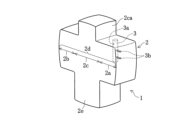
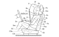
- FIG. 1A is a perspective view of a cushion in a state in which inflation and deployment have been completed in an airbag device according to an embodiment, viewed from an oblique direction.
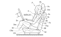
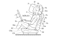
- FIG. 1B is a view from the side of the vehicle in which the cushion is inflated and deployed in the airbag device of FIG. 1A.
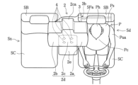
- FIG. 1C is a diagram of the airbag device of FIG. 1A in which the cushion is inflated and deployed, viewed from above the vehicle.
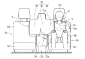
- FIG. 1D is a view of the airbag device of FIG. 1A in a state where the cushion is inflated and deployed, as seen from the front of the vehicle.
- FIG. 1A is a perspective view of a cushion in a state in which inflation and deployment have been completed in an airbag device according to an embodiment, viewed from an oblique direction.
- FIG. 1B is a view from the side of the vehicle in which the cushion is inflated and deployed in the airbag device of FIG. 1A.
- FIG. 1C is a diagram of
- FIG. 2A is a perspective view of a cushion in a state in which inflation and deployment have been completed in an airbag device according to a first modification of the embodiment, viewed from an oblique direction.
- FIG. 2B is a view from the side of the vehicle in which the cushion is inflated and deployed in the airbag device of FIG. 2A.
- FIG. 2C is a view of the airbag device of FIG. 2A in a state where the cushion is inflated and deployed, viewed from above the vehicle.
- FIG. 2D is a view of the airbag device of FIG. 2A in a state where the cushion is inflated and deployed, as seen from the front of the vehicle.
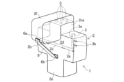
- FIG. 3A is a perspective view of a cushion in a state in which inflation and deployment have been completed in an airbag device according to a second modification of the embodiment, viewed from an oblique direction.
- FIG. 3B is a view from the side of the vehicle in which the cushion is inflated and deployed in the airbag device of FIG. 3A.
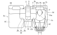
- FIG. 3C is a view from above the vehicle in which the cushion is inflated and deployed in the airbag device of FIG. 3A.
- FIG. 3D is a view of the airbag device of FIG. 3A in a state where the cushion is inflated and deployed, as seen from the front of the vehicle.
- FIG. 3B is a view from the side of the vehicle in which the cushion is inflated and deployed in the airbag device of FIG. 3A.
- FIG. 3C is a view from above the vehicle in which the cushion is inflated and deployed in the airbag device of FIG. 3A.
- FIG. 3D is a view of the airbag device of FIG. 3A in
- FIG. 4A is a perspective view of a cushion in a state in which inflation and deployment have been completed in an airbag device according to a third modification of the embodiment, viewed from an oblique direction.
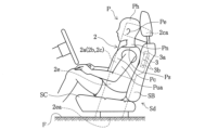
- FIG. 4B is a view from the side of the vehicle in which the cushion is inflated and deployed in the airbag device of FIG. 4A.
- FIG. 4C is a diagram of the airbag device of FIG. 4A in which the cushion is inflated and deployed, viewed from above the vehicle.
- FIG. 4D is a view of the airbag device of FIG. 4A in a state where the cushion is inflated and deployed, as seen from the front of the vehicle.
- FIG. 4B is a view from the side of the vehicle in which the cushion is inflated and deployed in the airbag device of FIG. 4A.
- FIG. 4C is a diagram of the airbag device of FIG. 4A in which the cushion is inflated and deployed, viewed from above the vehicle.
- FIG. 4D is a view of the airbag device of
- FIG. 5A is a perspective view of a cushion in a state in which inflation and deployment have been completed in an airbag device according to a fourth modification of the embodiment, viewed from an oblique direction.
- FIG. 5B is a view from the side of the vehicle in which the cushion is inflated and deployed in the airbag device of FIG. 5A.
- FIG. 6A is a perspective view of a cushion in a state in which inflation and deployment have been completed in an airbag device according to a fifth modification of the embodiment, viewed from an oblique direction.
- FIG. 6B is a view from the side of the vehicle in which the cushion is inflated and deployed in the airbag device of FIG. 6A.
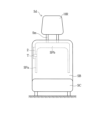
- FIG. 7 is a front view of the seat with the cushion stored.
- the term "occupant” refers to, for example, a dummy for frontal collision tests (Hybrid III AM50/NHTSA [National Highway Traffic Safety Administration] standards [49CFR Part572 Subpart E and O]).
- Hybrid III AM50/NHTSA National Highway Traffic Safety Administration
- the present invention is also applicable to other human dummies.
- upper and “upper side” refer to the direction of the head of the occupant P seated in the regular position of the seats Sd and Sn
- lower and “lower side” refer to the direction toward the feet of the occupant P.
- the "regular position” refers to a position where the back of the occupant P vertically contacts the backrest portion SB at the center position in the left-right direction of each seat cushion SC in the seats Sd and Sn.
- front and “front side” may mean the front direction of the occupant P seated in the normal position of seats Sd and Sn
- “rear” and “rear side” may mean the back direction of the occupant P.
- left and “left side” may refer to the left hand direction of the occupant P seated in the regular positions of the seats Sd and Sn
- “right” and “right side” may refer to the right hand direction of the occupant P.
- the inner side surface of the far side of the backrest part SB of one of the two seats (for example, the driver's seat Sd and the passenger seat Sn) arranged in the width direction of the vehicle.
- This is an airbag device 1 to be installed.
- 1A to 1D show an example in which the airbag device 1 is provided on the driver's seat Sd side. Below, before explaining the airbag device 1, the seat (driver's seat Sd) on which the airbag device 1 is mounted will be explained.
- the driver's seat Sd includes a seat cushion SC and a backrest portion SB.
- a headrest HR is attached to the upper end of the backrest portion SB via a rod-shaped support member Sm.
- the driver's seat Sd may have a backrest portion SB and a headrest HR integrally formed.
- FIG. 7 there is a door (not shown) on the right side of the page.
- the far side is the side of the driver's seat Sd that is far from the door.
- the seat cushion SC has a pad provided above a seat pan (not shown), and the pad is covered with a skin material.
- a pad is provided on the front side of the seat frames SFa and SFb, and the pad is covered with a skin material.
- the cushion 2 can be stored in the seat Sd by being rolled up or folded into a bellows shape when placed flat.
- the cushion 2 in the stowed form is stored along the side SFa of the seat frame of the seat Sd, as shown in FIG.
- the cushion 2 is stored within the far side of the seat Sd.
- a fixing device T is used to fix the cushion 2 in the storage form to the far side side SFa of the seat frame. Therefore, displacement of the cushion 2 can be suppressed in the event of a collision or the like.
- the arrangement and number of fixtures T are not limited to this embodiment.
- the airbag device 1 includes a cushion 2 and an inflator 3 (see FIG. 1C).
- the cushion 2 is a bag made of cloth, which is constructed by preparing in advance a required number of base fabrics of a desired shape and sewing predetermined locations such as the outer periphery of these base fabrics.
- the inflator 3 is a device that injects gas that inflates the cushion 2.
- a cylindrical inflator 3 is disposed inside the cushion 2, which receives a signal from a sensor and jets gas into the cushion 2 from a hole 3a provided on the outer surface thereof.
- the cushion 2 is attached to the inner side of the backrest part SB using two stud bolts 3b that are provided in a protruding manner at an appropriate interval in the longitudinal direction on the outer surface opposite to the hole 3a of the inflator 3. It is attached to the side SFa of the frame.
- the fixture T for fixing the cushion 2 can be omitted.
- the inflator 3 is fixed to the side part SFa of the seat frame by stud bolts 3b.
- the stud bolt 3b is passed through the insertion hole of the storage portion, so that the storage portion is also fixed to the side portion SFa of the seat frame.
- the main chamber 2d of the cushion 2 is inflated and deployed so that it rides on the front of the driver's seat Sd and the front of the passenger's seat Sn, so that the main chamber 2d of the cushion 2 is expanded to the far side of the passenger P seated on the driver's seat Sd and/or the front passenger's seat Sn. It has a first part 2a and a second part 2b that protect the parts, and a central part 2c that expands and deploys between the first part 2a and the second part 2b. Specifically, the first part 2a restrains the side part of the occupant P seated in the driver's seat Sd, and the second part 2b restrains the side part of the passenger P seated in the passenger seat Sn. It is something.
- first portion 2a, second portion 2b, and central portion 2c are not strict.
- vertical dimensions, longitudinal dimensions, and lateral dimensions of the main chamber 2d are not limited to those illustrated in the drawings, and can be adjusted in accordance with the shape and arrangement of the seats Sd and Sn.
- the first portion 2a, the second portion 2b, and the central portion 2c are integrally formed in one main chamber 2d.
- the main chamber 2d When viewed from the front side of the vehicle, the main chamber 2d has a shape in which the central portion 2c has an extension portion 2ca that extends upward from the first portion 2a and the second portion 2b, and has a required thickness in the longitudinal direction of the vehicle. It is formed by joining an appropriate number of base fabric panels so that it has the following properties.
- the first portion 2a and the second portion 2b have lengths in the vertical and longitudinal directions that can receive the sides of the torso of the occupant P, such as the shoulder Ps, chest Pc, and upper arm Pua.
- the central portion 2c also has an extension portion 2ca that extends in the vertical and longitudinal directions so as to be able to receive the rear side of the head Ph from the neck Pn to the ears Pe of the occupant P, for example. It has a length.
- the inflator 3 receives a signal from the sensor and injects gas into the main chamber 2d from the hole 3a provided on its outer surface.
- the main chamber 2d is expanded and expanded.
- the first portion 2a and second portion 2b which expand and deploy and ride on the front of the driver's seat Sd and the front passenger seat Sn, may damage, for example, the shoulders Ps, chest Pc, and upper arms of the occupant P who moves due to the impact. part Pua, and restrains the movement of the occupant P.
- the height of the console box CB is higher than the upper surface of the seat cushion SC of the seats Sd and Sn, even if the cushion 2 is composed of only the main chamber 2d, it can be inflated and deployed.
- the bottom surface of the main chamber 2d can be supported by the top surface of the console box CB.
- the bottom surface of the main chamber 2d cannot be supported when the main chamber 2d is inflated and deployed.
- the cushion 2 of this embodiment includes a lower chamber 2e extending downward from a part of the main chamber 2d. Specifically, the lower chamber 2e extends downward from the central portion 2c of the main chamber 2d.
- the lower chamber 2e When the lower chamber 2e is inflated and deployed, the lower end 2ea of the lower chamber 2e contacts the upper surface CBa of the console box CB, which is located at a lower position than the upper surface of the seat cushion SC of the seat Sd, as shown in FIGS. 1B and 1D. It is designed to be possible.
- the lower chamber 2e has a generally rectangular parallelepiped shape, and the length in the vertical direction of the lower chamber 2e is defined so that the bottom surface 2ea of the lower chamber 2e reaches and contacts the upper surface CBa of the console box CB during inflation and deployment.
- the width of the lower chamber 2e in the left-right direction is the same as the width in the left-right direction of the console box CB installed between the driver's seat Sd and the passenger seat Sn.
- the width of the lower chamber 2e in the left-right direction may be slightly longer than the width of the console box CB in the left-right direction, so that the width just fits in the space between the driver's seat Sd and the passenger seat Sn without creating a gap. However, it may be shorter than the width of the console box CB in the left-right direction.
- the vertical dimensions, longitudinal dimensions, and lateral dimensions of the lower chamber 2e are not limited to those illustrated in each figure, and can be adjusted as appropriate according to the shapes, installation positions, etc. of the seats Sd and Sn. .
- the lower chamber 2e is formed by joining an appropriate number of base fabric panels so as to project downward from the main chamber 2d.
- the lower chamber 2e of this embodiment is formed integrally with the main chamber 2d, forming one bag.
- a gas guide may be provided in the storage portion of the inflator 3.
- the gas guide may be configured to have a first outlet that opens to the main chamber 2d and a second outlet that opens to the lower chamber 2e as outlets for the gas injected from the inflator 3.
- the cushion 2 expands and deploys toward the side of the far side of one of the seats Sd and Sn to suppress the movement of the occupant P who attempts to move in the direction in which the impact is applied.
- a lower chamber 2e extending downward from the central portion 2c of the main chamber 2d.
- the lower chamber 2e has a shape that allows the lower end 2ea of the lower chamber 2e to contact the upper surface CBa of the console box CB, which is located at a lower position than the upper surface of the seat cushion SC of the seats Sd and Sn, when inflated and deployed. It is configured.
- the present embodiment is applied to a vehicle in which the height of the console box CB is lower than the upper surface of the seat cushion SC of the seats Sd and Sn, the space in the portion lower than the upper surface of the seat cushion SC is The lower chamber 2e expands and expands downward to fill the area.
- the inflated and deployed lower chamber 2e supports the lower part of the main chamber 2d that protects the side part of the occupant P.
- the vertical swing is reduced, and the deployment behavior of the cushion 2 is stabilized.
- the inflated and deployed lower chamber 2e supports the lower part of the main chamber 2d that protects the side part of the occupant P. Therefore, according to the present embodiment, it is possible to prevent the cushion 2 from tilting upon completion of inflation and deployment.
- the airbag device 1 of this embodiment has stable deployment behavior of the cushion 2 and exhibits high restraint performance against a side collision from the far side.
- the main chamber 2d includes a first portion 2a that restrains the side portion of the occupant P seated in the driver's seat Sd, and a second portion 2a that restrains the side portion of the occupant P seated in the passenger seat Sn. Both portions 2b are provided. Therefore, the occupant P in either seat Sd or Sn can be appropriately protected, and the restraint performance for the occupant P can be improved. Further, even when the occupant P in the driver's seat Sd moves to the opposite side from the initial stage of the collision due to the impact force of the collision, for example, a collision with the occupant in the passenger seat Sn can be effectively avoided.
- the lower chamber 2e is formed as a separate chamber separated from the main chamber 2d.
- the lower chamber 2e is formed into a rectangular parallelepiped by joining an appropriate number of base fabric panels so that it projects downward from the main chamber 2d, and is joined to the lower surface of the main chamber 2d.
- the lower chamber 2e of this modification communicates with the main chamber 2d via a first vent hole 4 provided on the lower surface of the central portion 2c of the main chamber 2d.
- the inflator 3 that receives a signal from the sensor blows gas into the main chamber 2d from the hole 3a provided on its outer surface to inflate and deploy the main chamber 2d. After the main chamber 2d expands and deploys, gas flows into the lower chamber 2e from the first vent hole 4, and the lower chamber 2e expands and deploys.
- the number of first vent holes 4 to be provided and the size (inner diameter) of each hole may be designed in consideration of the timing of expanding and deploying the lower chamber 2e. If the total opening area of the first vent holes 4 is made sufficiently large, gas can be quickly supplied to the lower chamber 2e almost simultaneously with the expansion and development of the main chamber 2d, and the lower chamber 2e can be expanded quickly. can be done. Depending on design requirements, the total opening area of the first vent hole 4 may be adjusted to be slightly smaller to reduce the required time lag between the expansion and expansion of the main chamber 2d and the lower chamber 2e. It can also be caused.
- the lower chamber 2e expands and deploys downward so as to fill the space below the upper surface of the seat cushion SC. Since the lower chamber 2e serves as a supporting portion, the main chamber 2d is stabilized during inflation and deployment.
- the lower chamber 2e is configured in such a shape that the lower end 2ea of the lower chamber 2e can come into contact with the floor surface F of the vehicle during inflation and deployment.
- the shape of the lower chamber 2e is a rectangular parallelepiped that is slightly longer in the vertical direction than in the above embodiment.
- the length of the lower chamber 2e in the vertical direction is determined so that the bottom surface of the lower chamber 2e reaches and contacts the floor surface F during inflation and deployment.
- the width of the lower chamber 2e in the left-right direction is set so as to fit in the space between the driver's seat Sd and the passenger seat Sn without creating a gap.
- the inflator 3 when a shock is applied to the vehicle due to a collision or the like, the inflator 3 receives a signal from the sensor and injects gas into the main chamber 2d, causing the main chamber 2d to expand and expand. Further, a part of the gas injected into the main chamber 2d is supplied to the lower chamber 2e via the first vent hole 4. As a result, the lower chamber 2e expands and deploys downward so as to fill the entire space where the console box CB would be present in a typical vehicle. Since the lower chamber 2e serves as a supporting portion, the main chamber 2d is stabilized during inflation and deployment.
- the airbag device 1 exhibits occupant restraint performance in response to a side collision.
- the lower chamber 2e is formed as a separate chamber from the main chamber 2d, but the lower chamber 2e may be formed integrally with the main chamber 2d.
- the extension portion 2ca of the central portion 2c receives the head Ph of the occupant P.
- further improvement in performance may be required so that the entire head Ph of the occupant P can be received more reliably from the initial stage of a vehicle collision to the final stage when the impact of the collision is gone.
- the central portion 2c of the cushion 2 is provided with at least a larger portion of the vehicle than the first portion 2a and the second portion 2b when inflated and deployed.
- a protrusion 2f is formed that protrudes in the front direction and can receive the entire head Ph of the occupant P.
- the protruding portion 2f also has a function of catching the occupant P who moves diagonally forward in the event of a collision from an oblique direction. Note that the configuration of the lower chamber 2e in this modification is the same as that in the first modification, so a description thereof will be omitted.
- the protruding portion 2f is configured to cover the upper surface of the extension portion 2ca so that its upper surface is above the top of the head of the occupant P seated in the driver's seat Sd or passenger seat Sn. Provided for. Then, an appropriate number of base fabric panels are sewn to form the covering portion and the portion protruding forward from the front surface of the extension portion 2ca.
- the protruding portion 2f is formed in a separate chamber separated from the main chamber 2d.
- the protrusion 2f communicates with the main chamber 2d via a second vent hole 5 provided on the upper surface of the extension 2ca.
- the size (inner diameter) of the second vent hole 5 is such that gas flows into the protrusion 2f in the latter half of the expansion and deployment of the main chamber 2d, and there is a time lag between the expansion and deployment of the main chamber 2d and the expansion and deployment of the protrusion 2f.
- the size is such that it will occur.
- the inflator 3 that receives the signal from the sensor blows out gas into the main chamber 2d from the hole 3a provided on the outer surface of the inflator 3.
- the main chamber 2d is expanded and expanded.
- the main chamber 2d After the main chamber 2d expands and develops to some extent, gas flows into the protrusion 2f from the second vent hole 5, and the protrusion 2f expands and develops.
- the main chamber 2d which has less time to protect the occupant P from the collision, can be inflated and deployed before the protrusion 2f.
- This inflated and deployed protrusion 2f prevents the entire occupant P and his/her head Ph from moving due to the impact, not only when an impact is applied from the side of the occupant P, but also when an impact is applied from diagonally in front of the occupant P. can be accepted with certainty.
- the tether 6 is a string-like or thin band-like member.
- the same material as the base fabric constituting the cushion 2 may be used for the tether 6.
- a non-stretchable material can be suitably used for the tether 6, but a stretchable material can also be used.
- the protrusion 2f is stabilized by connecting the protrusion 2f and the lower chamber 2e with the tether 6, so that when a collision occurs from the side, the portion of the extension 2ca of the protrusion 2f that expands and deploys in the forward direction Even if the head Ph of the occupant P moves and causes a collision, the movement of the head Ph can be effectively suppressed.
- the fifth modification in which the attachment position of the other end 6b of the tether 6 is changed also provides the same effects as the fourth modification.
- the attachment position of the one end 6a of the tether 5 to the protrusion 2f can be changed from the front lower part of the protrusion 2f to the bottom front part.
- the same effects as in the fourth modification and the fifth modification are achieved.
- the configuration and function of the lower chamber 2e in this modification are the same as in the first modification.
- the bottom surface of the lower chamber 2e may be provided with a non-slip portion having a larger coefficient of friction than the surface of the base fabric panel constituting the lower chamber 2e.
- a non-slip portion with a large coefficient of friction on the bottom surface of the lower chamber 2e, when the lower chamber 2e expands and deploys and the bottom surface of the lower chamber 2e comes into contact with the top surface of the console box CB or the floor surface F of the passenger compartment. , the bottom surface of the lower chamber 2e becomes less slippery and easier to stay in place.
- the anti-slip portion having such a large coefficient of friction can be provided by applying a resin coating to the bottom surface of the lower chamber 2e.
- the anti-slip portion may be provided by sewing a patch to the bottom of the lower chamber 2e.
- the first portion 2a, second portion 2b, and central portion 2c of the main chamber 2d may be formed by a plurality of divided chambers.
- the gas injected from the inflator 3 may be directly sent to the first portion 2a, second portion 2b, and central portion 2c so that the gas can be inflated and deployed without time lag.
- the configuration shown in the first modification and the configuration shown in the third modification may be combined. That is, the lower chamber 2e is configured as a separate chamber separated from the main chamber 2d, and is communicated with the main chamber 2d via the first vent hole 4 provided on the lower surface of the central portion 2c, and the protruding portion 2f is It may be configured as a separate chamber separated from the main chamber 2d and communicated with the main chamber 2d via a second vent hole 5 provided on the upper surface of the extension portion 2ca of the central portion 2c.
- the airbag device 1 may be housed in the far side side portion of the passenger seat Sn.
- the second vent hole 5 may be provided on the front surface of the extension portion 2ca in addition to the upper surface. Alternatively, the second vent hole 5 may be provided only on the front surface of the extension portion 2ca.
- the cushion 2 and the tether 6 are not limited to sewing, and may be joined by any method such as gluing or welding, as long as a predetermined strength can be obtained.
- the cushion 2 is not limited to one in which an appropriate number of base fabric panels are joined by sewing or the like, but may be formed using a so-called "one-piece weaving" technique.
- the airbag device 1 is not limited to the front seat of the vehicle, but may be installed on the rear seat.
- the airbag device 1 may be attached to the seats in the second or third row.
- the present invention is applicable to an airbag device that protects the side of an occupant.
- Airbag device cushion 2a First part 2b Second part 2c Central part 2ca Extension part 2d Main chamber 2e Lower chamber 2ea Lower end part 2f Projection part 3 Inflator 4 First vent hole 5 Second vent hole 6 Connecting member (tether) Sd seat (driver's seat) Sn seat (passenger seat) SB Backrest SC Seat cushion
Landscapes
- Engineering & Computer Science (AREA)
- Mechanical Engineering (AREA)
- Aviation & Aerospace Engineering (AREA)
- Transportation (AREA)
- Air Bags (AREA)
Abstract
コンソールボックスがシートクッションの上面よりも低い車両やコンソールボックスが無い車両であっても、膨張展開時にクッションの展開挙動が安定すると共に、乗員拘束時にクッションが傾かないエアバッグ装置を実現する。 クッション2と、クッション2を膨張させるガスを噴射するインフレータ3とを備えたエアバッグ装置1である。クッション2は、乗員の一方の側部の側に膨張展開するメインチャンバ2dと、メインチャンバ2dの一部から下方に向かって延設された下方チャンバ2eとを有する。下方チャンバ2eは、膨張展開時、下方チャンバ2eの下端部が、座席のシートクッションの上面よりも低い位置にあるコンソールボックス上部表面もしくは車両の床面に接触可能となるように形成されている。
Description
本発明は、例えば、車室内で車両の幅方向に並んで設けられた座席のうち、何れか一方の座席の背もたれ部の前記幅方向の中央側(以下、ファーサイドという場合がある。)の側面部に設置されるエアバッグ装置に関するものである。
従来から、ファーサイドからの衝撃に対応した乗員の拘束性能を有するエアバッグ装置が知られている。この種のエアバッグ装置では、乗員のファーサイドの側部を保護するためにクッションが車室の中央側で膨張展開する。
特許文献1には、運転席と助手席の間に設置されたコンソールボックスに設けられる座席間エアバッグ装置が記載されている。この座席間エアバッグ装置のクッションは、正面視I字状に膨張展開する主バッグと、主バッグを通じてガスが供給されると、主バッグの上下方向中央部から助手席側に突出して膨張展開する副バッグを備えている。
ところで、従来の座席間エアバッグ装置では、運転席と助手席の間にコンソールボックスが設置されていること、及び、コンソールボックスの高さが座席のシートクッションの上面の位置よりも高いことを前提として、クッションの形状を規定している。具体的に、従来の座席間エアバッグ装置のクッションは、膨張展開時にクッションの底面がコンソールボックスの上面に接触する形状であることが多い。このような形状とすることで、クッションが膨張展開したときにコンソールボックスから反力が得られ、コンソールボックスを支えにすることができる。
そのため、従来の座席間エアバッグ装置は、コンソールボックスがシートクッションの上面よりも低い車両やコンソールボックスが無い車両に適用する場合は、膨張展開時にコンソールボックスから反力が得られず、クッションの展開挙動の安定性が失われる。加えて、従来の座席間エアバッグ装置は、乗員拘束時にクッションの下方が安定しないため、クッションに傾きが生じやすく、乗員の拘束性能が低下する。
本願発明者は、最新のEuro-NCAPプロトコルへの対応を検討する過程で、コンソールボックスが低い(もしくは無い)車両におけるファーサイド衝突時の性能を改善するためには、クッションの形状を改良することが望ましいと考えた。
本発明は、このような事情に鑑みてなされたものであり、コンソールボックスがシートクッションの上面よりも低い車両やコンソールボックスが無い車両であっても、膨張展開時にクッションの展開挙動が安定すると共に、乗員拘束時にクッションが傾かないエアバッグ装置を実現することを目的とする。
本発明は、車両の幅方向に並んで配置された座席のうち何れか一方の座席の背もたれ部の前記幅方向の中央側の側面部に設置されるエアバッグ装置である。
本発明に係るエアバッグ装置は、クッションと、クッションを膨張させるガスを噴射するインフレータと、を備え、クッションは、座席の一方の側部の側に膨張展開するメインチャンバと、メインチャンバの一部から下方に向かって延設された下方チャンバと、を有し、下方チャンバは、膨張展開時、下方チャンバの下端部が、座席のシートクッションの上面よりも低い位置にあるコンソールボックス上部表面もしくは車両の床面に接触可能となるように形成されている。
本発明は、メインチャンバは、車両の幅方向に並んで配置された座席のうち何れか一方の座席に着座している乗員の側部を受け止める第1部分及び何れか他方の座席に着座している乗員の側部を受け止める第2部分と、これら第1部分と第2部分の間に設けられた中央部分とを有し、下方チャンバは、中央部分から下方に向かって延設されている構成でもよい。
本発明では、メインチャンバは、第1部分、中央部分および第2部分が連続して一体的に形成されており、下方チャンバは、メインチャンバとは分離された別チャンバで形成されていてもよい。
本発明では、メインチャンバと下方チャンバは、第1ベントホールを介して連通している構成でもよい。
本発明は、インフレータが、メインチャンバに取り付けられており、インフレータから噴射されるガスの一部は、メインチャンバから第1ベントホールを介して下方チャンバに供給される構成でもよい。
本発明では、中央部分に、クッションの膨張展開時、第1部分及び第2部分よりも、少なくとも車両の前方方向に突出して、乗員の頭部、及び、斜め前方に移動する乗員を受け止めることが可能な突出部を設けてもよい。
本発明は、メインチャンバは、第1部分、中央部分および第2部分が連続して一体的に形成されており、突出部は、メインチャンバとは分離された別チャンバで形成されていてもよい。
本発明では、メインチャンバと突出部は、第2ベントホールを介して連通している構成でもよい。
本発明は、突出部の前面下方部分と下方チャンバの底面前方部分とを繋ぐ連結部材を備えていてもよい。
本発明は、突出部の前面下方部分と中央部分の前面下方部分とを繋ぐ連結部材を備えていてもよい。
本発明のエアバッグ装置のクッションは、座席の一方の側部の側に、具体的には座席のファーサイドの側部の側に膨張展開するメインチャンバに加え、メインチャンバの一部から下方に向かって延設された下方チャンバを備えている。下方チャンバは、膨張展開時、下方チャンバの下端部が、座席のシートクッションの上面よりも低い位置にあるコンソールボックス上部表面もしくは車両の床面に接触可能となる形状に構成されている。これにより、本発明では、コンソールボックスの高さが座席のシートクッションの上面よりも低い車両に適用される場合は、シートクッションの上面よりも低い部分の空間を埋めるように、下方チャンバが膨張展開する。また、本発明では、コンソールボックスが存在しない車両に適用される場合は、コンソールボックスに相当する部分の空間全域を埋めるように、下方チャンバが膨張展開する。
そのため、本発明では、側面衝突時に膨張展開した下方チャンバが、乗員の側部を保護するメインチャンバの下側部分の支えとなる。この支え部分があることで、本発明では、クッションが膨張展開する際に、上下方向の揺動が減少し、クッションの展開挙動が安定する。また、本発明によれば、膨張展開完了時にクッションに傾きが生じることも防止できる。
以下、図面を参照しながら、本発明の実施形態を詳細に説明する。なお、以下の実施形態は、本発明の一例であって、本発明、その適用物、あるいはその用途の範囲を制限することを意図するものではない。
本発明において「乗員」とは、一例を示せば、前面衝突試験用のダミー(Hybrid III AM50/ NHTSA [National Highway Traffic Safety Administration:米国高速道路交通安全協会]の規格[49CFR Part572 Subpart E 及びO] にて決められた前面衝突試験用人体ダミー)に準拠した、米国における平均的な男性に相当する体格を有するものをいい、概略サイズは、身長175cm、座高88cm、体重78kgである。但し、本発明はその他の人体ダミーに対しても適用可能である。
また、本明細書において、「上」、「上側」とは座席Sd,Snの正規の位置に着座した乗員Pの頭部方向を、「下」、「下側」とは乗員Pの足元方向を意味する場合がある。ここで、「正規の位置」とは、座席Sd,SnにおけるそれぞれのシートクッションSCの左右方向の中心位置で、背もたれ部SBに乗員Pの背中が上下に亘って接する位置をいう。また、「前」、「前側」とは座席Sd,Snの正規の位置に着座した乗員Pの正面方向を、「後」、「後ろ側」とは乗員Pの背面方向を意味する場合がある。また、「左」、「左側」とは座席Sd,Snの正規の位置に着座した乗員Pの左手方向を、「右」、「右側」とは乗員Pの右手方向を意味する場合がある。
本実施形態は、車両内で車両の幅方向に並んで配置された2つの座席(例えば運転席Sdと助手席Sn)のうち、何れか一方の座席の背もたれ部SBのファーサイドの側面内部に設置されるエアバッグ装置1である。図1A~図1Dでは、運転席Sd側にエアバッグ装置1を設ける例を示している。以下では、エアバッグ装置1について説明する前に、エアバッグ装置1が搭載される座席(運転席Sd)について説明を行う。
[座席の概略構成について]
運転席Sdは、図7に示すように、シートクッションSCと、背もたれ部SBとを備えている。背もたれ部SBの上端部には、棒状の支持部材Smを介して、ヘッドレストHRが取り付けられている。運転席Sdは、背もたれ部SBとヘッドレストHRが一体的に形成されたものであってもよい。図7では、紙面右側にドア(不図示)がある。運転席Sdのドアから遠い側がファーサイドである。
運転席Sdは、図7に示すように、シートクッションSCと、背もたれ部SBとを備えている。背もたれ部SBの上端部には、棒状の支持部材Smを介して、ヘッドレストHRが取り付けられている。運転席Sdは、背もたれ部SBとヘッドレストHRが一体的に形成されたものであってもよい。図7では、紙面右側にドア(不図示)がある。運転席Sdのドアから遠い側がファーサイドである。
シートクッションSCは、シートパン(不図示)の上側にパッドが設けられ、パッドが表皮材により被覆されている。背もたれ部SBでは、シートフレームSFa,SFbの前側にパッドが設けられ、パッドが表皮材により被覆されている。
クッション2は、平置き状態においてロール状に巻く、又は、蛇腹状に折り畳むことにより、座席Sdに収納される時の収納形態となる。収納形態のクッション2は、図7に示すように、座席Sdのシートフレームの側部SFaに沿って収納される。
具体的に、クッション2は、座席Sdのファーサイドの側部内に収納される。本実施形態では、固定具Tを用いて、収納形態のクッション2をシートフレームのファーサイドの側部SFaに固定している。そのため、衝突時などにクッション2の位置ずれを抑制することができる。なお、固定具Tの配置や個数は、本実施形態に限定されない。
[エアバッグ装置の構成について]
エアバッグ装置1は、クッション2と、インフレータ3(図1C参照)を備えている。クッション2は、所要の形状の基布を必要数あらかじめ準備し、これらの基布の外周部など所定の箇所を縫製することにより構成された布製の袋体である。インフレータ3は、クッション2を膨張させるガスを噴射する装置である。
エアバッグ装置1は、クッション2と、インフレータ3(図1C参照)を備えている。クッション2は、所要の形状の基布を必要数あらかじめ準備し、これらの基布の外周部など所定の箇所を縫製することにより構成された布製の袋体である。インフレータ3は、クッション2を膨張させるガスを噴射する装置である。
エアバッグ装置1では、クッション2の内部に、センサーからの信号を受信してその外側面に設けた孔3aからクッション2の内部にガスを噴出する筒形状のインフレータ3を配置している。
クッション2は、インフレータ3の孔3aの反対側の外側面に、その長手方向に適宜の間隔をあけて突出状に設けられた2本のスタッドボルト3bを用いて、背もたれ部SBの内部のサイドフレームの側部SFaに取り付けられる。なお、本実施形態のように、インフレータ3のスタットボルト3bによってもクッション2を固定することができる場合、クッション2を固定する固定具Tは省略することもできる。
インフレータ3の収納部では、スタッドボルト3bによりインフレータ3がシートフレームの側部SFaに固定される。この固定では、収納部の挿通孔にスタッドボルト3bが通されることで、収納部もシートフレームの側部SFaに固定される。
[膨張完了状態のクッションについて]
膨張展開が完了した状態(以下、「膨張完了状態」と言う。)のクッション2の構成について、図1A~図1Dを参照しながら説明を行う。なお、図1Bにおいて、乗員Pは正規の位置に着座しているものとしている。
膨張展開が完了した状態(以下、「膨張完了状態」と言う。)のクッション2の構成について、図1A~図1Dを参照しながら説明を行う。なお、図1Bにおいて、乗員Pは正規の位置に着座しているものとしている。
クッション2のメインチャンバ2dは、運転席Sdの前面と助手席Snの前面に乗り上がる状態に膨張展開して、運転席Sd及び/又は助手席Snに着座している乗員Pのファーサイドの側部を保護する第1部分2a及び第2部分2bと、これら第1部分2aと第2部分2bの間で膨張展開する中央部分2cを備えている。具体的に、第1部分2aは運転席Sdに着座している乗員Pの側部を拘束するものであり、第2部分2bは助手席Snに着座している乗員Pの側部を拘束するものである。なお、これら第1部分2a、第2部分2b、中央部分2cの境界は厳密なものではない。また、メインチャンバ2dの上下方向の寸法、前後方向の寸法、左右方向の寸法は、図面に例示したものに限らず、座席Sd,Snの形状や配置に併せて調整することができる。
本実施形態では、これら第1部分2a、第2部分2b、及び中央部分2cを一つのメインチャンバ2dで一体的に形成している。メインチャンバ2dは、車両の前方側から見た場合に、第1部分2a及び第2部分2bよりも上方に延長した延長部2caを中央部分2cに有する形状で、車両の前後方向に所要の厚みを有するように、適数枚の基布パネルを接合して形成している。
第1部分2aと第2部分2bは、乗員Pの胴体の側部、例えば肩部Ps、胸部Pc、上腕部Puaを受け止めることができる上下方向及び前後方向の長さを有している。また、中央部分2cは、乗員Pの側部に加え、その延長部2caによって、例えば、乗員Pの首Pnから耳Peまでの頭部Phの後側を受け止めることができる上下方向及び前後方向の長さを有している。
エアバッグ装置1では、側面衝突、斜め衝突、オフセット衝突などの発生時、センサーからの信号を受信したインフレータ3は、その外側面に設けた孔3aからメインチャンバ2dの内部にガスを噴出し、メインチャンバ2dを膨張展開させる。側面衝突などの時、膨張展開して運転席Sd及び助手席Snの前面に乗り上がった第1部分2a及び第2部分2bが、衝撃によって移動する乗員Pの例えば肩部Ps、胸部Pc、上腕部Puaを受け止め、乗員Pの移動を抑制する。
ここで、コンソールボックスCBの高さが座席Sd,SnのシートクッションSCの座面の上面の位置よりも高い車両であれば、クッション2がメインチャンバ2dのみで構成されていても、膨張展開したメインチャンバ2dの底面をコンソールボックスCBの上面で支えることができる。しかし、コンソールボックスCBの上面がシートクッションSCの上面よりも低い車両の場合は、メインチャンバ2dが膨張展開したときにその底面を支えることができない。
そこで、本実施形態のクッション2は、メインチャンバ2dの一部から下方に向かって延設された下方チャンバ2eを備えている。具体的に、下方チャンバ2eは、メインチャンバ2dの中央部分2cから下方に向かって延設されている。下方チャンバ2eは、膨張展開時、図1B及び図1Dに示すように、下方チャンバ2eの下端部2eaが座席SdのシートクッションSCの上面よりも低い位置にあるコンソールボックスCBの上部表面CBaに接触可能となるように形成されている。
下方チャンバ2eは概ね直方体状であり、膨張展開時に、下方チャンバ2eの底面2eaがコンソールボックスCBの上部表面CBaに到達して接触するように、下方チャンバ2eの上下方向の長さが規定されている。また、下方チャンバ2eの左右方向の幅は、運転席Sdと助手席Snの間に設置されているコンソールボックスCBの左右方向の幅と同じにしている。あるいは、下方チャンバ2eの左右方向の幅は、コンソールボックスCBの左右方向の幅よりも若干長くして運転席Sdと助手席Snの間の空間に隙間を生じないように丁度収まる幅としてもよいし、コンソールボックスCBの左右方向の幅よりも短くしてもよい。
下方チャンバ2eの上下方向の寸法、前後方向の寸法、左右方向の寸法については、各図に例示したものに限らず、座席Sd,Snの形状、設置位置等に合わせて適宜調整することができる。
本実施形態では、下方チャンバ2eは、メインチャンバ2dから下方向に突出した形状となるように、適数枚の基布パネルを接合して形成している。本実施形態の下方チャンバ2eは、メインチャンバ2dと一体的に形成されたものであり、1つの袋体を形成している。
なお、インフレータ3の収納部にガスガイドを設けてもよい。ガスガイドは、インフレータ3から噴射されるガスの出口として、メインチャンバ2dに開口する第1出口と、下方チャンバ2eに開口する第2出口を有するように構成してもよい。
[本実施形態の効果等]
本実施形態では、クッション2が、座席Sd,Snの一方のファーサイドの側部の側に膨張展開して衝撃が加わった方向に移動しようとする乗員Pの移動を抑制するメインチャンバ2dに加え、メインチャンバ2dの中央部分2cから下方に向かって延設された下方チャンバ2eを備えている。そして、下方チャンバ2eは、膨張展開時、下方チャンバ2eの下端部2eaが、座席Sd,SnのシートクッションSCの上面よりも低い位置にあるコンソールボックスCBの上部表面CBaに接触可能となる形状に構成されている。
本実施形態では、クッション2が、座席Sd,Snの一方のファーサイドの側部の側に膨張展開して衝撃が加わった方向に移動しようとする乗員Pの移動を抑制するメインチャンバ2dに加え、メインチャンバ2dの中央部分2cから下方に向かって延設された下方チャンバ2eを備えている。そして、下方チャンバ2eは、膨張展開時、下方チャンバ2eの下端部2eaが、座席Sd,SnのシートクッションSCの上面よりも低い位置にあるコンソールボックスCBの上部表面CBaに接触可能となる形状に構成されている。
これにより、本実施形態では、コンソールボックスCBの高さが座席Sd,SnのシートクッションSCの上面よりも低い車両に適用される場合であっても、シートクッションSCの上面よりも低い部分の空間を埋めるように、下方チャンバ2eが下方に向けて膨張展開する。
そのため、本実施形態では、膨張展開した下方チャンバ2eが、乗員Pの側部を保護するメインチャンバ2dの下側部分の支えとなる。この支え部分があることで、本実施形態では、クッション2が膨張展開するときに、上下方向の揺動が減少し、クッション2の展開挙動が安定する。
車両のファーサイドからの側面衝突では、衝突初期は、慣性力により乗員Pが衝突発生側に移動する。具体的に、運転席Sdに着座している乗員Pを基準としてファーサイドの側面衝突が発生した場合、乗員Pは、衝突初期に、メインクッション2の第1部分2aに衝突する。
このとき、本実施形態では、膨張展開した下方チャンバ2eが、乗員Pの側部を保護するメインチャンバ2dの下側部分の支えとなっている。そのため、本実施形態によれば、膨張展開完了時にクッション2に傾きが生じることも防止できる。
本実施形態のエアバッグ装置1は、クッション2の展開挙動が安定し、ファーサイドからの側面衝突に対して高い拘束性能を発揮する。
本実施形態では、メインチャンバ2dが、運転席Sdに着座している乗員Pの側部を拘束する第1部分2aと、助手席Snに着座している乗員Pの側部を拘束する第2部分2bを両方備えている。そのため、何れの座席Sd,Snの乗員Pも適切に保護し、乗員Pの拘束性能を向上させることができる。また、例えば衝突の衝撃力により、運転席Sdの乗員Pが、衝突初期とは反対側に移動したときも、助手席Snの乗員との衝突を効果的に避けることができる。
[実施形態の第1変形例]
本変形例では、図2A~図2Dに示すように、下方チャンバ2eは、メインチャンバ2dとは分離された別チャンバで形成している。下方チャンバ2eは、メインチャンバ2dから下方向に突出した形状となるように、適数枚の基布パネルを接合して直方体状に形成した上で、メインチャンバ2dの下面と接合している。本変形例の下方チャンバ2eは、メインチャンバ2dの中央部分2cの下面に設けた第1ベントホール4を介して、メインチャンバ2dと連通している。
本変形例では、図2A~図2Dに示すように、下方チャンバ2eは、メインチャンバ2dとは分離された別チャンバで形成している。下方チャンバ2eは、メインチャンバ2dから下方向に突出した形状となるように、適数枚の基布パネルを接合して直方体状に形成した上で、メインチャンバ2dの下面と接合している。本変形例の下方チャンバ2eは、メインチャンバ2dの中央部分2cの下面に設けた第1ベントホール4を介して、メインチャンバ2dと連通している。
本変形例では、側面衝突時、センサーからの信号を受信したインフレータ3は、その外側面に設けた孔3aからメインチャンバ2dの内部にガスを噴出し、メインチャンバ2dを膨張展開させる。そして、メインチャンバ2dが膨張展開した後、第1ベントホール4から下方チャンバ2eにガスが流入し、下方チャンバ2eが膨張展開する。
ここで、第1ベントホール4を設ける個数と各ホールのサイズ(内径)は、下方チャンバ2eを膨張展開させるタイミングを考慮して設計すればよい。第1ベントホール4の開孔面積の合計値を十分に大きくすれば、メインチャンバ2dの膨張展開とほぼ同時に下方チャンバ2eにもガスを速やかに供給することができ、下方チャンバ2eを速やかに膨張させることができる。また、設計上の要求によっては、第1ベントホール4の開孔面積の合計値を若干小さく調整することで、メインチャンバ2dの膨張展開と下方チャンバ2eの膨張展開との間に所要のタイムラグを生じさせることもできる。
本変形例では、シートクッションSCの上面よりも低い部分の空間を埋めるように、下方チャンバ2eが下方に向けて膨張展開する。そして、下方チャンバ2eが支え部分となることで、膨張展開時にメインチャンバ2dが安定する。
そのため、コンソールボックスCBがシートクッションSCの上面よりも低い車両であっても、クッション2が膨張展開する際に上下方向の揺動が減少し、クッション2の展開挙動が安定する。また、下方チャンバ2eが支えとなるので、膨張展開完了時にクッション2に傾きが生じることも防止できる。特に、本変形例では、第1ベントホール4の開孔面積の合計値を適宜調整することで、下方チャンバ2eの膨張展開のタイミングを最適化することが容易となる。
[実施形態の第2変形例]
近年、自動運転の技術が進んでいる。自動運転の車両では、自動運転モードで走行中は運転者を必要とせず自律走行が可能となり、走行中の乗員の姿勢や状態について自由度が増すことになる。例えば、前列の座席を車両に対して前向き方向から180度回転させた状態とし、前列の座席に着座した乗員が、後列の座席に着座した乗員と顔が向き合う状態で会話しながら車両を走行させることが可能となる。このため、座席を自在に回転できるようにするために、運転席Sdと助手席Snの間にコンソールボックスを設けない車両が想定される。
近年、自動運転の技術が進んでいる。自動運転の車両では、自動運転モードで走行中は運転者を必要とせず自律走行が可能となり、走行中の乗員の姿勢や状態について自由度が増すことになる。例えば、前列の座席を車両に対して前向き方向から180度回転させた状態とし、前列の座席に着座した乗員が、後列の座席に着座した乗員と顔が向き合う状態で会話しながら車両を走行させることが可能となる。このため、座席を自在に回転できるようにするために、運転席Sdと助手席Snの間にコンソールボックスを設けない車両が想定される。
本変形例は、上記のようなコンソールボックスが無い車両に適用されるものである。本変形例では、図3A~図3Dに示すように、下方チャンバ2eは、膨張展開時に、下方チャンバ2eの下端部2eaが車両の床面Fに接触可能となる形状に構成されている。
具体的に、下方チャンバ2eの形状は、上述の実施形態の場合よりもやや上下方向に長い直方体状である。そして、膨張展開時に下方チャンバ2eの底面が床面Fに到達して接触するように、下方チャンバ2eの上下方向の長さが規定されている。また、下方チャンバ2eの左右方向の幅は、運転席Sdと助手席Snの間の空間に隙間を生じないように収まる幅としている。
本変形例では、衝突などによって車両に衝撃が加わると、センサーからの信号を受けたインフレータ3が、メインチャンバ2d内にガスを噴射し、メインチャンバ2dが膨張展開する。また、メインチャンバ2dに噴射されたガスの一部は、第1ベントホール4を介して下方チャンバ2eに供給される。これにより、一般的な車両であればコンソールボックスCBが存在する部分の空間全域を埋めるように、下方チャンバ2eが下方に向けて膨張展開する。そして、下方チャンバ2eが支え部分となることで、膨張展開時にメインチャンバ2dが安定する。
そのため、コンソールボックスCBが無い車両であっても、クッション2が膨張展開する際に上下方向の揺動が減少し、クッション2の展開挙動が安定する。また、下方チャンバ2eが支えとなるので、膨張展開完了時にクッション2に傾きが生じることも防止できる。このように、下方チャンバ2eの効果により、エアバッグ装置1は、側面衝突に対応した乗員の拘束性能を発揮する。
なお、本変形例では、メインチャンバ2dとは別のチャンバで下方チャンバ2eを形成しているが、下方チャンバ2eは、メインチャンバ2dと一体的に形成されたものであってもよい。
[実施形態の第3変形例]
上述の実施形態の場合、中央部2cの延長部2caは、乗員Pの頭部Phを受け止めるものである。しかし、車両衝突時の初期から衝突の影響がなくなる終期にかけて、乗員Pの頭部Phの全体をより確実に受け止めることができるように、更なる性能の向上が求められる場合がある。
上述の実施形態の場合、中央部2cの延長部2caは、乗員Pの頭部Phを受け止めるものである。しかし、車両衝突時の初期から衝突の影響がなくなる終期にかけて、乗員Pの頭部Phの全体をより確実に受け止めることができるように、更なる性能の向上が求められる場合がある。
本変形例では、乗員Pの頭部Phの全体をより確実に受け止めることができるように、クッション2の中央部分2cに、膨張展開時、第1部分2a及び第2部分2bよりも、少なくとも車両の前方方向に突出して乗員Pの頭部Phの全体を受け止めることが可能な突出部2fを形成したものである。この突出部2fは、斜め方向などからの衝突時に、斜め前方に移動する乗員Pを受け止める機能も備えている。なお、本変形例における下方チャンバ2eの構成は、第1変形例と同じであるから、説明を省略する。
突出部2fは、図4A~図4Dに示すように、その上面が運転席Sdや助手席Snに着座した乗員Pの頭頂部よりも上方となるように、延長部2caの上面に覆いかぶさるように設ける。そして、この覆いかぶさった部分と延長部2caの前面から前方方向に突出した部分から構成されるように、適数枚の基布パネルを縫製して形成している。
突出部2fは、メインチャンバ2dとは分離された別チャンバで形成している。突出部2fは、延長部2caの上面に設けた第2ベントホール5を介してメインチャンバ2dと連通している。
第2ベントホール5のサイズ(内径)は、メインチャンバ2dの膨張展開の後半に、突出部2fにガスが流入し、メインチャンバ2dの膨張展開と突出部2fの膨張展開との間にタイムラグが生じるような大きさとしている。
延長部2caに突出部2fを設けた本変形例では、側面衝突時、センサーからの信号を受信したインフレータ3は、その外側面に設けた孔3aからメインチャンバ2dの内部にガスを噴出し、メインチャンバ2dを膨張展開させる。
そして、メインチャンバ2dがある程度膨張展開した後に、第2ベントホール5から突出部2fにガスが流入し、突出部2fが膨張展開する。本変形例では、ファーサイドの衝突時に、衝突から乗員Pを保護するまでに時間の猶予の少ないメインチャンバ2dを、突出部2fに先んじて膨張展開させることができる。この膨張展開した突出部2fにより、乗員Pの側方から衝撃が加わった場合のみならず、乗員Pの斜め前方から衝撃が加わった場合でも、衝撃によって移動する乗員Pやその頭部Phの全体を確実に受け止めることができる。
[実施形態の第4変形例]
本変形例は、第3変形例で説明した突出部2fの前面下方部分と、下方チャンバ2eの底面前方部分を、テザー6で繋いだものである。テザー6の一端6aは、図5A~図5Bに示すように、突出部2fの前面下方部分と縫着されている。また、テザー6の他端6bは、下方チャンバ2eの底面前方部分と縫着されている。テザー6は、連結部材に相当する。
本変形例は、第3変形例で説明した突出部2fの前面下方部分と、下方チャンバ2eの底面前方部分を、テザー6で繋いだものである。テザー6の一端6aは、図5A~図5Bに示すように、突出部2fの前面下方部分と縫着されている。また、テザー6の他端6bは、下方チャンバ2eの底面前方部分と縫着されている。テザー6は、連結部材に相当する。
テザー6は、紐状又は細い帯状の部材である。テザー6には、クッション2を構成する基布と同一材料を用いてもよい。テザー6は、例えば非伸縮性の素材を好適に用いることができるが、伸縮性の素材を用いることもできる。
本変形例では、突出部2fと下方チャンバ2eをテザー6で繋ぐことにより突出部2fが安定するので、側面方向などからの衝突時、突出部2fの延長部2caの前方方向に膨張展開した部分に乗員Pの頭部Phが移動して衝突した場合でも、頭部Phの移動を効果的に抑制することができる。
[実施形態の第5変形例]
本変形例では、第3変形例で説明した突出部2fの前面下方部分と、メインチャンバ2dの中央部分2cの前面下方部分を、テザー6で繋いだものである。テザー6の一端6aは、図6A~図6Bに示すように、突出部2fの前面下方部分と縫着されている。また、テザー6の他端6bは、メインチャンバ2dの中央部分2cの前面下方部分と縫着されている。
本変形例では、第3変形例で説明した突出部2fの前面下方部分と、メインチャンバ2dの中央部分2cの前面下方部分を、テザー6で繋いだものである。テザー6の一端6aは、図6A~図6Bに示すように、突出部2fの前面下方部分と縫着されている。また、テザー6の他端6bは、メインチャンバ2dの中央部分2cの前面下方部分と縫着されている。
テザー6の他端6bの取付け位置を変更した第5変形例においても、第4変形例と同様の作用効果を奏する。
なお、第4変形例及び第5変形例において、テザー5の一端6aの突出部2fへの取付け位置は、突出部2fの前面下方部分から底面前方部分に変更することも可能である。この場合も第4変形例及び第5変形例と同様の作用効果を奏する。また、本変形例における下方チャンバ2eの構成及び機能は、第1変形例と同じである。
[その他の変形例]
上述の実施形態において、下方チャンバ2eの底面に、下方チャンバ2eを構成する基布パネルの表面よりも大きな摩擦係数を有する滑り止め部分を設けるようにしてもよい。下方チャンバ2eの底面に大きな摩擦係数を有する滑り止め部分を設けることで、下方チャンバ2eが膨張展開して下方チャンバ2eの底面がコンソールボックスCBの上面もしくは車室の床面Fと接触したときに、下方チャンバ2eの底面が滑りにくくなって所定の位置にとどまりやすくなる。なお、このような大きな摩擦係数を有する滑り止め部分は、下方チャンバ2eの底面に樹脂コーティングを施すことによって設けることができる。あるいは、滑り止め部分は、下方チャンバ2eの底面にパッチを縫い付けることによって設けてもよい。
上述の実施形態において、下方チャンバ2eの底面に、下方チャンバ2eを構成する基布パネルの表面よりも大きな摩擦係数を有する滑り止め部分を設けるようにしてもよい。下方チャンバ2eの底面に大きな摩擦係数を有する滑り止め部分を設けることで、下方チャンバ2eが膨張展開して下方チャンバ2eの底面がコンソールボックスCBの上面もしくは車室の床面Fと接触したときに、下方チャンバ2eの底面が滑りにくくなって所定の位置にとどまりやすくなる。なお、このような大きな摩擦係数を有する滑り止め部分は、下方チャンバ2eの底面に樹脂コーティングを施すことによって設けることができる。あるいは、滑り止め部分は、下方チャンバ2eの底面にパッチを縫い付けることによって設けてもよい。
上述の実施形態において、メインチャンバ2dの第1部分2a、第2部分2b、中央部分2cは、区分けされた複数のチャンバで形成してもよい。この場合、インフレータ3から噴射されるガスを第1部分2a、第2部分2b、中央部分2cに直接送り込むなどしてタイムラグの無い状態で膨張展開できるようにすればよい。
上述の実施形態において、第1変形例で示した構成と第3変形例で示した構成を組み合わせてもよい。すなわち、下方チャンバ2eは、メインチャンバ2dとは分離された別チャンバで構成し、中央部分2cの下面に設けた第1ベントホール4を介してメインチャンバ2dと連通させると共に、突出部2fは、メインチャンバ2dとは分離された別チャンバで構成し、中央部2cの延長部2caの上面に設けた第2ベントホール5を介してメインチャンバ2dと連通させてもよい。
上述の実施形態において、エアバッグ装置1は、助手席Snのファーサイドの側面部に収納してもよい。
上述の実施形態において、第2ベントホール5は、延長部2caの上面に加えて前面にも第2ベントホール5を設けてもよい。あるいは、延長部2caの前面のみに第2ベントホール5を設けてもよい。
上述の実施形態において、クッション2とテザー6との接合は、所定の強度が得られるのであれば、縫製に限らず、接着、溶着など、何れの方法で連結してもよい。
上述の実施形態において、クッション2は、適数枚の基布パネルを縫製などによって接合したものの限らず、いわゆる「ワンピースウィービング(one-piece weaving)」の技術を用いて形成したものでもよい。
上述の実施形態において、エアバッグ装置1は、車両のフロントシートに限らず、リアシートに設置してもよい。車両の2列目もしくは3列目の座席が車両の幅方向に並んで配置されている場合、当該2列目もしくは3列目の座席に、エアバッグ装置1を取り付けてもよい。
本発明は、乗員の側部を保護するエアバッグ装置に適用可能である。
1 エアバッグ装置
2 クッション
2a 第1部分
2b 第2部分
2c 中央部分
2ca 延長部
2d メインチャンバ
2e 下方チャンバ
2ea 下端部
2f 突出部
3 インフレータ
4 第1ベントホール
5 第2ベントホール
6 連結部材(テザー)
Sd 座席(運転席)
Sn 座席(助手席)
SB 背もたれ部
SC シートクッション
2 クッション
2a 第1部分
2b 第2部分
2c 中央部分
2ca 延長部
2d メインチャンバ
2e 下方チャンバ
2ea 下端部
2f 突出部
3 インフレータ
4 第1ベントホール
5 第2ベントホール
6 連結部材(テザー)
Sd 座席(運転席)
Sn 座席(助手席)
SB 背もたれ部
SC シートクッション
Claims (10)
- 車両の幅方向に並んで配置された座席のうち何れか一方の座席の背もたれ部の前記幅方向の中央側の側面部に設置されるエアバッグ装置であって、
クッションと、
前記クッションを膨張させるガスを噴射するインフレータと、を備え、
前記クッションは、前記座席の一方の側部の側に膨張展開するメインチャンバと、前記メインチャンバの一部から下方に向かって延設された下方チャンバと、を有し、
前記下方チャンバは、膨張展開時、前記下方チャンバの下端部が、前記座席のシートクッションの上面よりも低い位置にあるコンソールボックス上部表面もしくは前記車両の床面に接触可能となるように形成されている、エアバッグ装置。 - 前記メインチャンバは、何れか一方の前記座席に着座している乗員の側部を受け止める第1部分及び何れか他方の座席に着座している乗員の側部を受け止める第2部分と、これら第1部分と第2部分の間に設けられた中央部分とを有し、前記下方チャンバは、前記中央部分から下方に向かって延設されている、請求項1に記載のエアバッグ装置。
- 前記メインチャンバは、前記第1部分、前記中央部分および前記第2部分が連続して一体的に形成されており、前記下方チャンバは、前記メインチャンバとは分離された別チャンバで形成されている、請求項2に記載のエアバッグ装置。
- 前記メインチャンバと前記下方チャンバは、第1ベントホールを介して連通している、請求項3に記載のエアバッグ装置。
- 前記インフレータは、前記メインチャンバに取り付けられており、
前記インフレータから噴射されるガスの一部は、前記メインチャンバから前記第1ベントホールを介して前記下方チャンバに供給される、請求項4に記載のエアバッグ装置。 - 前記中央部分に、クッションの膨張展開時、前記第1部分及び前記第2部分よりも、少なくとも車両の前方方向に突出して、前記乗員の頭部、及び、斜め前方に移動する前記乗員を受け止めることが可能な突出部を設けた、請求項2に記載のエアバッグ装置。
- 前記メインチャンバは、前記第1部分、前記中央部分および前記第2部分が連続して一体的に形成されており、前記突出部は、前記メインチャンバとは分離された別チャンバで形成されている、請求項6に記載のエアバッグ装置。
- 前記メインチャンバと前記突出部は、第2ベントホールを介して連通している、請求項7に記載のエアバッグ装置。
- 前記突出部の前面下方部分と前記下方チャンバの底面前方部分とを繋ぐ連結部材を備える、請求項6乃至8の何れか1つに記載のエアバッグ装置。
- 前記突出部の前面下方部分と前記中央部分の前面下方部分とを繋ぐ連結部材を備える、請求項6乃至8の何れか1つに記載のエアバッグ装置。
Applications Claiming Priority (2)
| Application Number | Priority Date | Filing Date | Title |
|---|---|---|---|
| JP2022-077423 | 2022-05-10 | ||
| JP2022077423 | 2022-05-10 |
Publications (1)
| Publication Number | Publication Date |
|---|---|
| WO2023218769A1 true WO2023218769A1 (ja) | 2023-11-16 |
Family
ID=88730039
Family Applications (1)
| Application Number | Title | Priority Date | Filing Date |
|---|---|---|---|
| PCT/JP2023/011736 WO2023218769A1 (ja) | 2022-05-10 | 2023-03-24 | エアバッグ装置 |
Country Status (1)
| Country | Link |
|---|---|
| WO (1) | WO2023218769A1 (ja) |
Citations (7)
| Publication number | Priority date | Publication date | Assignee | Title |
|---|---|---|---|---|
| JP2009006860A (ja) * | 2007-06-28 | 2009-01-15 | Toyoda Gosei Co Ltd | 車両の乗員保護装置 |
| JP2010221739A (ja) * | 2009-03-19 | 2010-10-07 | Toyoda Gosei Co Ltd | エアバッグ装置 |
| KR20110047559A (ko) * | 2009-10-30 | 2011-05-09 | 현대자동차주식회사 | 차량용 센터 에어백 |
| US20170232922A1 (en) * | 2016-02-16 | 2017-08-17 | Tk Holdings Inc. | Center side airbag module |
| JP2017149351A (ja) * | 2016-02-26 | 2017-08-31 | ダイハツ工業株式会社 | 車両構造 |
| WO2019228898A1 (en) * | 2018-05-30 | 2019-12-05 | Autoliv Development Ab | An air-bag |
| US20200317155A1 (en) * | 2019-04-02 | 2020-10-08 | Ford Global Technologies, Llc | Vehicle seat side airbag |
-
2023
- 2023-03-24 WO PCT/JP2023/011736 patent/WO2023218769A1/ja unknown
Patent Citations (7)
| Publication number | Priority date | Publication date | Assignee | Title |
|---|---|---|---|---|
| JP2009006860A (ja) * | 2007-06-28 | 2009-01-15 | Toyoda Gosei Co Ltd | 車両の乗員保護装置 |
| JP2010221739A (ja) * | 2009-03-19 | 2010-10-07 | Toyoda Gosei Co Ltd | エアバッグ装置 |
| KR20110047559A (ko) * | 2009-10-30 | 2011-05-09 | 현대자동차주식회사 | 차량용 센터 에어백 |
| US20170232922A1 (en) * | 2016-02-16 | 2017-08-17 | Tk Holdings Inc. | Center side airbag module |
| JP2017149351A (ja) * | 2016-02-26 | 2017-08-31 | ダイハツ工業株式会社 | 車両構造 |
| WO2019228898A1 (en) * | 2018-05-30 | 2019-12-05 | Autoliv Development Ab | An air-bag |
| US20200317155A1 (en) * | 2019-04-02 | 2020-10-08 | Ford Global Technologies, Llc | Vehicle seat side airbag |
Similar Documents
| Publication | Publication Date | Title |
|---|---|---|
| WO2021059766A1 (ja) | エアバッグ装置及び車両用シート | |
| WO2018142382A1 (en) | Overhead airbag assemblies | |
| WO2021149576A1 (ja) | エアバッグ装置 | |
| WO2022075216A1 (ja) | エアバッグ装置 | |
| CN113002475A (zh) | 侧面安全气囊装置 | |
| JPWO2019193987A1 (ja) | サイドエアバッグ装置 | |
| JP2022077924A (ja) | 車両用シート・エアバッグ一体型乗員保護装置 | |
| JP7270826B2 (ja) | エアバッグ装置及び車両用シート | |
| KR102460804B1 (ko) | 에어백 장치의 제조 방법 및 에어백 장치 | |
| US11260819B2 (en) | Airbag apparatus | |
| JP7530509B2 (ja) | エアバッグ装置 | |
| WO2023218769A1 (ja) | エアバッグ装置 | |
| WO2022097509A1 (ja) | シート内蔵エアバッグ装置 | |
| JP7510326B2 (ja) | サイドエアバッグ装置 | |
| JP7450461B2 (ja) | エアバッグ装置 | |
| JP2019077216A (ja) | サイドエアバッグ装置 | |
| WO2024057972A1 (ja) | エアバッグシステム | |
| WO2024095697A1 (ja) | 乗員拘束装置 | |
| WO2024034375A1 (ja) | サイドエアバッグ装置 | |
| WO2024062969A1 (ja) | 車両用シート | |
| WO2024128054A1 (ja) | サイドエアバッグ装置 | |
| WO2021166530A1 (ja) | サイドエアバッグ装置 | |
| EP4368460A1 (en) | Airbag device | |
| JP7411602B2 (ja) | エアバッグ装置 | |
| WO2022210077A1 (ja) | エアバッグ装置 |
Legal Events
| Date | Code | Title | Description |
|---|---|---|---|
| 121 | Ep: the epo has been informed by wipo that ep was designated in this application |
Ref document number: 23803252 Country of ref document: EP Kind code of ref document: A1 |