WO2023218765A1 - 負極活物質の製造方法、負極活物質および二次電池 - Google Patents
負極活物質の製造方法、負極活物質および二次電池 Download PDFInfo
- Publication number
- WO2023218765A1 WO2023218765A1 PCT/JP2023/011354 JP2023011354W WO2023218765A1 WO 2023218765 A1 WO2023218765 A1 WO 2023218765A1 JP 2023011354 W JP2023011354 W JP 2023011354W WO 2023218765 A1 WO2023218765 A1 WO 2023218765A1
- Authority
- WO
- WIPO (PCT)
- Prior art keywords
- negative electrode
- active material
- group
- electrode active
- organic solvent
- Prior art date
- Legal status (The legal status is an assumption and is not a legal conclusion. Google has not performed a legal analysis and makes no representation as to the accuracy of the status listed.)
- Ceased
Links
Classifications
-
- H—ELECTRICITY
- H01—ELECTRIC ELEMENTS
- H01M—PROCESSES OR MEANS, e.g. BATTERIES, FOR THE DIRECT CONVERSION OF CHEMICAL ENERGY INTO ELECTRICAL ENERGY
- H01M4/00—Electrodes
- H01M4/02—Electrodes composed of, or comprising, active material
- H01M4/36—Selection of substances as active materials, active masses, active liquids
-
- H—ELECTRICITY
- H01—ELECTRIC ELEMENTS
- H01M—PROCESSES OR MEANS, e.g. BATTERIES, FOR THE DIRECT CONVERSION OF CHEMICAL ENERGY INTO ELECTRICAL ENERGY
- H01M4/00—Electrodes
- H01M4/02—Electrodes composed of, or comprising, active material
- H01M4/36—Selection of substances as active materials, active masses, active liquids
- H01M4/38—Selection of substances as active materials, active masses, active liquids of elements or alloys
-
- H—ELECTRICITY
- H01—ELECTRIC ELEMENTS
- H01M—PROCESSES OR MEANS, e.g. BATTERIES, FOR THE DIRECT CONVERSION OF CHEMICAL ENERGY INTO ELECTRICAL ENERGY
- H01M4/00—Electrodes
- H01M4/02—Electrodes composed of, or comprising, active material
- H01M4/36—Selection of substances as active materials, active masses, active liquids
- H01M4/58—Selection of substances as active materials, active masses, active liquids of inorganic compounds other than oxides or hydroxides, e.g. sulfides, selenides, tellurides, halogenides or LiCoFy; of polyanionic structures, e.g. phosphates, silicates or borates
-
- H—ELECTRICITY
- H01—ELECTRIC ELEMENTS
- H01M—PROCESSES OR MEANS, e.g. BATTERIES, FOR THE DIRECT CONVERSION OF CHEMICAL ENERGY INTO ELECTRICAL ENERGY
- H01M4/00—Electrodes
- H01M4/02—Electrodes composed of, or comprising, active material
- H01M4/36—Selection of substances as active materials, active masses, active liquids
- H01M4/58—Selection of substances as active materials, active masses, active liquids of inorganic compounds other than oxides or hydroxides, e.g. sulfides, selenides, tellurides, halogenides or LiCoFy; of polyanionic structures, e.g. phosphates, silicates or borates
- H01M4/583—Carbonaceous material, e.g. graphite-intercalation compounds or CFx
- H01M4/587—Carbonaceous material, e.g. graphite-intercalation compounds or CFx for inserting or intercalating light metals
-
- Y—GENERAL TAGGING OF NEW TECHNOLOGICAL DEVELOPMENTS; GENERAL TAGGING OF CROSS-SECTIONAL TECHNOLOGIES SPANNING OVER SEVERAL SECTIONS OF THE IPC; TECHNICAL SUBJECTS COVERED BY FORMER USPC CROSS-REFERENCE ART COLLECTIONS [XRACs] AND DIGESTS
- Y02—TECHNOLOGIES OR APPLICATIONS FOR MITIGATION OR ADAPTATION AGAINST CLIMATE CHANGE
- Y02E—REDUCTION OF GREENHOUSE GAS [GHG] EMISSIONS, RELATED TO ENERGY GENERATION, TRANSMISSION OR DISTRIBUTION
- Y02E60/00—Enabling technologies; Technologies with a potential or indirect contribution to GHG emissions mitigation
- Y02E60/10—Energy storage using batteries
Definitions
- the present invention relates to a method for producing a negative electrode active material.
- the present invention also relates to a negative electrode active material obtained by the manufacturing method and a secondary battery containing the negative electrode active material.
- Non-aqueous electrolyte secondary batteries are used in portable devices, hybrid vehicles, electric vehicles, household storage batteries, etc., and are required to have a good balance of multiple characteristics such as electrical capacity, safety, and operational stability. ing.
- Nonaqueous electrolyte secondary batteries mainly use lithium intercalation compounds that release lithium ions from between the layers as negative electrode materials, and use materials such as graphite that can intercalate and release lithium ions between the crystal planes during charging and discharging.
- Various lithium ion batteries using carbonaceous materials as negative electrode active materials are being developed and put into practical use.
- silicon Since silicon has a large theoretical electric capacity, the use of silicon as a negative electrode active material is being considered for the purpose of increasing the capacity of lithium ion secondary batteries. However, silicon has a large difference in volumetric expansion and contraction when it is repeatedly charged and discharged, and silicon particles are destroyed during repeated charging and discharging. As a result, there is a demand for improvement in the cycle characteristics of secondary batteries using silicon as a negative electrode active material.
- Patent Document 1 focuses on silicon oxycarbide as an active material that has both cycle characteristics and high capacity. It is described that silicon oxycarbide has a lower volumetric expansion rate due to Li occlusion than silicon and silicon oxide, and exhibits stable cycle characteristics.
- Patent Document 2 discloses that in the production of an active material containing silicon oxycarbide, the initial Coulombic efficiency is increased by firing a heat-treated material containing silicon in hydrogen or an inert gas containing 10% by volume or more of hydrogen. It is described that an active material can be obtained in which the battery capacity is increased while maintaining the same.
- Patent Document 3 describes an active material made of a composite of silicon-based fine particles and a silicon-containing polymer by hydrolyzing a silane compound and then polycondensing it in the presence of a dispersant and silicon-based fine particles.
- an object of the present invention is to provide a method for producing a negative electrode active material that provides a secondary battery with a high capacity retention rate.
- a method for producing a negative electrode active material including the following mixing step (A), drying step (B), and baking step (C).
- Firing step (C) A step of firing the dried product obtained in the drying step (B) at a high temperature in an inert gas atmosphere.
- the amount of the organic solvent (b) used is such that the total mass of the nanosilicon dispersion, the carbon source resin, the polysiloxane compound, and the organic solvent (b) is 100 mass.
- [4] The method for producing a negative electrode active material according to any one of [1] to [3], wherein in the mixing step (A), the organic solvent (b) has a boiling point of 110° C. or higher at 1 atmosphere.
- [5] The method for producing a negative electrode active material according to any one of [1] to [4], wherein in the mixing step (A), ⁇ P in the Hansen solubility parameter of the organic solvent (b) is 6 MPa or more.
- [6] The method for producing a negative electrode active material according to any one of [1] to [5] above, wherein in the mixing step (A), ⁇ H in the Hansen solubility parameter of the organic solvent (b) is 5 MPa or more. .
- a negative electrode active material comprising silicon oxycarbide, silicon, and a carbonaceous phase, wherein the carbonaceous phase has an average size of 2 ⁇ m or less.
- a secondary battery comprising the negative electrode active material according to [7] above.
- a method for producing a negative electrode active material that provides a secondary battery with a high capacity retention rate is provided.
- the manufacturing method provides a negative electrode active material that provides a secondary battery with a high capacity retention rate, and a secondary battery using the negative electrode active material.
- the method for producing a negative electrode active material of the present invention includes the following mixing step (A), drying step (B), and baking step (C).
- Silicon oxycarbide has a three-dimensional network structure of silicon-oxygen-carbon skeleton and a structure containing a carbonaceous phase.
- the three-dimensional network structure of silicon-oxygen-carbon skeleton has high chemical stability, has a composite structure with a carbonaceous phase, and has a small volume change with respect to intercalation and desorption of lithium.
- silicon in the negative electrode plays the role of being the main component for developing charge and discharge performance, while silicon oxycarbide increases the volume of silicon particles during charge and discharge. The destruction of particles due to changes is further suppressed, and the cycleability of the lithium secondary battery is further improved.
- silicon oxycarbide has a structure that includes a three-dimensional network of silicon-oxygen-carbon skeleton and a carbonaceous phase, which facilitates the diffusion of lithium ions. Direct contact between the silicon and the electrolyte is prevented because the silicon is tightly wrapped in a composite structure of a silicon-oxygen-carbon skeleton and a carbonaceous phase. As a result, it is thought that deterioration of the performance of the active material is prevented to the maximum by avoiding the chemical reaction between silicon and the electrolyte during charging and discharging.
- silicon oxycarbide has a structure of a silicon-oxygen-carbon skeleton and a carbonaceous phase
- the silicon-oxygen-carbon skeleton contributes to improving capacity retention, and the carbonaceous phase stabilizes efficiency and lowers resistance. It is thought that this contributes to
- the carbonaceous phase is not uniformly dispersed in the silicon-oxygen-carbon skeleton, the volume expansion of silicon particles due to insertion of lithium ions during charging and discharging cannot be sufficiently suppressed, and as a result, the capacity of the negative electrode active material is maintained. It is thought that the rate will decrease. Therefore, the dispersibility of the carbonaceous phase in silicon oxycarbide is important.
- silicon oxycarbide containing silicon particles is produced by mixing silicon particles and a resin that becomes silicon oxycarbide by firing to form a mixture, and firing the resulting mixture.
- a method of mixing silicon particles and a resin dispersion is usually adopted.
- a polysiloxane resin is used as the resin that becomes silicon oxycarbide upon firing, and a carbon source resin is used as the resin that provides the carbonaceous phase.
- an organic solvent ( a) By adding the organic solvent (b) having a higher boiling point, the polysiloxane compound and the carbon source resin are mixed more uniformly, and the carbonaceous phase is uniformly dispersed in the silicon-oxygen-carbon skeleton. Conceivable.
- the nano-silicon dispersion used in the step (A) is a dispersion of nano-silicon particles having a volume average particle diameter on the order of nanometers. Since silicon has a small particle size, it is expected to improve cycle characteristics when used as a negative electrode active material in secondary batteries. When the volume average particle size is on the order of nanometers, the volume average particle size is in the nanometer unit, and the volume average particle size is usually from 1 to 999 nm. If the silicon particles exceed 1000 nm, the dispersibility of the dispersion may deteriorate, pressure during stirring may increase, and productivity may decrease.
- the volume average particle diameter of the nano silicon particles is preferably from 10 to 200 nm, more preferably from 10 to 100 nm, still more preferably from 20 to 70 nm.
- the volume average particle diameter is a D50 value that can be measured using a laser diffraction particle size analyzer or the like. D50 can be measured by dynamic light scattering using a laser particle size analyzer or the like.
- the volume average particle size of the nano silicon particles is the particle size at which the cumulative volume distribution curve is 50% when a volume cumulative distribution curve is drawn from the small diameter side in the particle size distribution.
- the specific surface area of the nano silicon particles is preferably from 100 to 400 m 2 /g, more preferably from 100 to 300 m 2 /g, and even more preferably from 100 to 230 m 2 /g from the viewpoint of electric capacity and initial Coulombic efficiency.
- the specific surface area is a value determined by the BET method, and can be determined by nitrogen gas adsorption measurement, for example, using a specific surface area measuring device.
- the shape of nano silicon particles may be granular, acicular, or flaky, but crystalline is preferable.
- the nanosilicon particles are crystalline, if the crystallite diameter obtained from the diffraction peak attributed to Si (111) in X-ray diffraction (hereinafter also referred to as "crystallite diameter") is in the range of 5 to 14 nm. , is preferable from the viewpoint of initial coulombic efficiency and capacity retention rate.
- the crystallite diameter is more preferably 12 nm or less, and even more preferably 10 nm or less.
- nano silicon particles preferably have a length in the major axis direction of 30 to 300 nm, and a thickness of 1 to 60 nm.
- a needle-like or flake-like shape having a so-called aspect ratio, which is the ratio of thickness to length, of 0.5 or less is preferable.
- the morphology of nano-silicon particles can be determined by measuring the average particle size using dynamic light scattering, but it is also possible to determine the morphology using transmission electron microscopy (TEM) or field emission scanning electron microscopy (FE-SEM). , samples with the above aspect ratio can be identified more easily and precisely.
- the sample can be cut with a focused ion beam (FIB) and the cross section can be observed by FE-SEM, or the sample can be sliced and observed by TEM. Accordingly, the state of nano silicon particles can be identified.
- FIB focused ion beam
- the aspect ratio of the nano-silicon particles is a calculation result based on 50 particles of the main part of the sample within the field of view reflected in the TEM image.
- the nano-silicon particles are dispersed in an organic solvent and used as a nano-silicon dispersion in the mixing step (A).
- the nano-silicon dispersion liquid can be prepared by pulverizing nano-silicon particles using a wet powder pulverizer.
- a dispersant may be added to the organic solvent in order to accelerate the pulverization of the nano-silicon particles.
- wet grinding devices include roller mills, high-speed rotary grinders, container-driven mills, and bead mills.
- organic solvent examples include ketones such as acetone, methyl ethyl ketone, methyl isobutyl ketone, and diisobutyl ketone; alcohols such as ethanol, methanol, normal propyl alcohol, and isopropyl alcohol; and aromatic compounds such as benzene, toluene, and xylene.
- ketones such as acetone, methyl ethyl ketone, methyl isobutyl ketone, and diisobutyl ketone
- alcohols such as ethanol, methanol, normal propyl alcohol, and isopropyl alcohol
- aromatic compounds such as benzene, toluene, and xylene.
- the type of dispersant includes aqueous and non-aqueous dispersants, with non-aqueous dispersants being preferred.
- Types of non-aqueous dispersants include polymer types such as polyethers, alcohols, polyalkylene polyamines, and polycarboxylic acid partial alkyl esters; low-molecular types such as polyhydric alcohol esters and alkyl polyamines; and polyphosphoric acid.
- Inorganic types such as salt types are exemplified.
- the solid content concentration of nanosilicon particles in the nanosilicon dispersion liquid is not particularly limited, but if the solvent and, if necessary, a dispersant are included, the total amount of the dispersant and nanosilicon particles is 100% by mass, and the concentration of nanosilicon particles is The amount of particles is preferably in the range of 5% to 40% by weight, more preferably 10% to 30% by weight.
- Examples of the polysiloxane compound used in the step (A) include resins containing at least one of a polycarbosilane structure, a polysilazane structure, a polysilane structure, and a polysiloxane structure. It may be a resin containing only these structures, or it may be a composite resin having at least one of these structures as a segment and chemically bonded to other polymer segments. Forms of composite include graft copolymerization, block copolymerization, random copolymerization, and alternating copolymerization.
- Examples include composite resins that have a graft structure in which polysiloxane segments are chemically bonded to the side chains of polymer segments, and composite resins that have a block structure in which polysiloxane segments are chemically bonded to the ends of polymer segments. .
- a polysiloxane compound in which the polysiloxane segment has a structural unit represented by the following general formula (S-1) and/or the following general formula (S-2) is preferred.
- the polysiloxane compound has a carboxyl group, an epoxy group, an amino group, or a polyether group at the side chain or terminal of the siloxane bond (Si-O-Si) main skeleton.
- R 1 represents an aromatic hydrocarbon group that may have a substituent, an alkyl group, an epoxy group, a carboxy group, or the like.
- R 2 and R 3 each represent an alkyl group, a cycloalkyl group, an aryl group, an aralkyl group, an epoxy group, a carboxy group, or the like.
- alkyl group examples include methyl group, ethyl group, propyl group, isopropyl group, butyl group, isobutyl group, sec-butyl group, tert-butyl group, pentyl group, isopentyl group, neopentyl group, tert-pentyl group, -Methylbutyl group, 2-methylbutyl group, 1,2-dimethylpropyl group, 1-ethylpropyl group, hexyl group, isohexyl group, 1-methylpentyl group, 2-methylpentyl group, 3-methylpentyl group, 1,1 -dimethylbutyl group, 1,2-dimethylbutyl group, 2,2-dimethylbutyl group, 1-ethylbutyl group, 1,1,2-trimethylpropyl group, 1,2,2-trimethylpropyl group, 1-ethyl- Examples include 2-methylpropyl group and 1-ethyl-1-methylpropyl
- aryl group examples include phenyl group, naphthyl group, 2-methylphenyl group, 3-methylphenyl group, 4-methylphenyl group, 4-vinylphenyl group, and 3-isopropylphenyl group.
- aralkyl group examples include benzyl group, diphenylmethyl group, naphthylmethyl group, and the like.
- polymer segments other than the polysiloxane segment possessed by the polysiloxane compound include vinyl polymer segments such as acrylic polymers, fluoroolefin polymers, vinyl ester polymers, aromatic vinyl polymers, and olefin polymers; Examples include polymer segments such as urethane polymer segments, ester polymer segments, and ether polymer segments. Among these, vinyl polymer segments are preferred.
- the polysiloxane compound may be a composite resin in which a polysiloxane segment and a polymer segment are bonded in a structure represented by the following structural formula (S-3), or may have a three-dimensional network polysiloxane structure.
- the carbon atom is a carbon atom constituting a polymer segment
- the two silicon atoms are silicon atoms constituting a polysiloxane segment.
- the polysiloxane segment that the polysiloxane compound has may have a functional group such as a polymerizable double bond that can react with heating in the polysiloxane segment.
- a functional group such as a polymerizable double bond that can react with heating in the polysiloxane segment.
- polymerizable double bond examples include vinyl groups and (meth)acryloyl groups. It is preferable that two or more polymerizable double bonds exist in the polysiloxane segment, more preferably 3 to 200, and still more preferably 3 to 50. Moreover, by using a composite resin in which two or more polymerizable double bonds are present as the polysiloxane compound, the crosslinking reaction can be easily caused to proceed.
- the polysiloxane segment may have a silanol group and/or a hydrolyzable silyl group.
- the hydrolyzable group in the hydrolyzable silyl group include a halogen atom, an alkoxy group, a substituted alkoxy group, an acyloxy group, a phenoxy group, a mercapto group, an amino group, an amide group, an aminooxy group, an iminooxy group, and an alkenyloxy group.
- the hydrolyzable silyl group becomes a silanol group.
- a hydrolytic condensation reaction proceeds between the hydroxyl group in the silanol group and the hydrolyzable group in the hydrolyzable silyl group to obtain a solid polysiloxane compound. can.
- the silanol group used in the present invention is a silicon-containing group having a hydroxyl group directly bonded to a silicon atom.
- the hydrolyzable silyl group referred to in the present invention is a silicon-containing group having a hydrolyzable group directly bonded to a silicon atom, and specifically, for example, a group represented by the following general formula (S-4). can be mentioned.
- R 4 is a monovalent organic group such as an alkyl group, aryl group or aralkyl group
- R 5 is a halogen atom, alkoxy group, acyloxy group, allyloxy group, mercapto group, amino group, amide group, aminooxy group, iminooxy group or alkenyloxy group.
- b is an integer from 0 to 2.
- alkyl group examples include methyl group, ethyl group, propyl group, isopropyl group, butyl group, isobutyl group, sec-butyl group, tert-butyl group, pentyl group, isopentyl group, neopentyl group, tert-pentyl group, -Methylbutyl group, 2-methylbutyl group, 1,2-dimethylpropyl group, 1-ethylpropyl group, hexyl group, isohexyl group, 1-methylpentyl group, 2-methylpentyl group, 3-methylpentyl group, 1,1 -dimethylbutyl group, 1,2-dimethylbutyl group, 2,2-dimethylbutyl group, 1-ethylbutyl group, 1,1,2-trimethylpropyl group, 1,2,2-trimethylpropyl group, 1-ethyl- Examples include 2-methylpropyl group and 1-ethyl-1-methylpropyl
- aryl group examples include phenyl group, naphthyl group, 2-methylphenyl group, 3-methylphenyl group, 4-methylphenyl group, 4-vinylphenyl group, and 3-isopropylphenyl group.
- aralkyl group examples include benzyl group, diphenylmethyl group, naphthylmethyl group, and the like.
- halogen atom examples include a fluorine atom, a chlorine atom, a bromine atom, an iodine atom, and the like.
- alkoxy group examples include methoxy group, ethoxy group, propoxy group, isopropoxy group, butoxy group, sec-butoxy group, tertiary-butoxy group, and the like.
- acyloxy group examples include formyloxy group, acetoxy group, propanoyloxy group, butanoyloxy group, pivaloyloxy group, pentanoyloxy group, phenylacetoxy group, acetoacetoxy group, benzoyloxy group, naphthoyloxy group, etc. Can be mentioned.
- allyloxy group examples include phenyloxy group and naphthyloxy group.
- alkenyloxy group examples include vinyloxy group, allyloxy group, 1-propenyloxy group, isopropenyloxy group, 2-butenyloxy group, 3-butenyloxy group, 2-petenyloxy group, 3-methyl-3-butenyloxy group, 2 -hexenyloxy group and the like.
- Examples of the polysiloxane segment having a structural unit represented by the general formula (S-1) and/or the general formula (S-2) include those having the following structures.
- the polymer segment may have various functional groups as necessary, as long as the effects of the present invention are not impaired.
- functional groups include carboxyl groups, blocked carboxyl groups, carboxylic anhydride groups, tertiary amino groups, hydroxyl groups, blocked hydroxyl groups, cyclocarbonate groups, epoxy groups, carbonyl groups, primary amide groups, secondary An amide group, a carbamate group, a functional group represented by the following structural formula (S-5), etc. can be used.
- the polymer segment may have a polymerizable double bond such as a vinyl group or a (meth)acryloyl group.
- the polysiloxane compound is preferably produced, for example, by the methods shown in (1) to (3) below.
- a polymer segment containing a silanol group and/or a hydrolyzable silyl group is prepared in advance, and this polymer segment and a silanol group and/or a hydrolyzable silyl group are , and a silane compound having a polymerizable double bond to perform a hydrolysis condensation reaction.
- a polymer segment containing a silanol group and/or a hydrolyzable silyl group is prepared in advance.
- a polysiloxane is also prepared in advance by subjecting a silane compound having a silanol group and/or a hydrolyzable silyl group and a polymerizable double bond to a hydrolytic condensation reaction. A method of mixing a polymer segment and polysiloxane and performing a hydrolytic condensation reaction.
- a polysiloxane compound is obtained by the method described above.
- Examples of polysiloxane compounds include the Ceranate (registered trademark) series (organic/inorganic hybrid coating resin; manufactured by DIC Corporation) and the Compoceran SQ series (silsesquioxane hybrid; manufactured by Arakawa Chemical Industries, Ltd.). .
- the carbon source resin is preferably a synthetic resin or natural chemical raw material having an aromatic functional group, which has good miscibility with the polysiloxane compound and is carbonized by high-temperature firing in an inert atmosphere.
- Examples of synthetic resins include thermoplastic resins such as polyvinyl alcohol and polyacrylic acid, and thermosetting resins such as phenol resins and furan resins.
- Natural chemical raw materials include heavy oil, especially tar pitches such as coal tar, light tar oil, medium tar oil, heavy tar oil, naphthalene oil, anthracene oil, coal tar pitch, pitch oil, mesophase pitch, oxygen-crosslinked petroleum pitch, and heavy oil. Examples include oil. Phenol resin is more preferred from the viewpoint of low cost availability and removal of impurities.
- the carbon source resin used in the mixing step (A) is preferably a resin containing an aromatic hydrocarbon moiety, and the resin containing an aromatic hydrocarbon moiety is preferably a phenol resin, an epoxy resin, or a thermosetting resin.
- the resin is preferably a resol type.
- the phenolic resin include SK resin (HE100C-30, manufactured by Air Water Co., Ltd.).
- the cresol resin include LC-100 (manufactured by Lignite Co., Ltd.).
- the carbon source resin may be dispersed or dissolved in an organic solvent when used in the mixing step (A).
- organic solvent examples include the same organic solvent as the organic solvent used in the nano-silicon particle dispersion, and when the carbon source resin is dispersed or dissolved in the organic solvent, the nano-silicon particle dispersion used in the mixing step (A) It is preferable to use the same organic solvent as that used in step (A) from the viewpoint of uniform mixing in the mixing step (A).
- the dispersion of nano silicon particles, the polysiloxane compound, the carbon source resin, and the organic solvent (a) contained in either the nano silicon dispersion or the carbon source resin have a boiling point higher than that of the organic solvent (a). and an organic solvent (b) containing the organic solvent.
- the polysiloxane compound and the carbon source resin used in the mixing step (A) may be mixed with the nanosilicon dispersion as they are, or may be dissolved or dispersed in an organic solvent and mixed.
- the organic solvent include the same organic solvents as mentioned above, and preferably the same organic solvent as the organic solvent used for the nanosilicon dispersion. When using an organic solvent, a dispersant may be used.
- the dispersant examples include the same dispersant as the dispersion liquid exemplified above for the nano-silicon dispersion liquid, and preferred dispersants are also the same.
- the organic solvent (a) is the organic solvent used in the dispersion of nano-silicon particles, or when the carbon source resin is dispersed or dissolved in an organic solvent, it is the organic solvent used for dispersion or dissolution. When the two are different, the one with the higher boiling point is used as the organic solvent (a).
- the drying temperature in the drying step (B) is appropriately selected depending on the boiling point of the organic solvent (b), which has a higher boiling point than the organic solvent (a).
- the boiling point is the boiling point at 1 atmosphere.
- the organic solvent (b) is preferably an organic solvent whose boiling point is 20° C. or more higher than the drying temperature in the drying step (B), preferably an organic solvent whose boiling point is 40° C. or more higher than the drying temperature.
- an organic solvent (a) with a boiling point of 60°C or higher and lower than 80°C it is preferable to use an organic solvent (b), and it is more preferable to use an organic solvent (b) having a boiling point of 120° C. or higher.
- Examples of the organic solvent (a) having a boiling point of 60° C. or higher and lower than 80° C. include methyl ethyl ketone and isopropanol, and a mixture of methyl ethyl ketone and isopropanol is preferred.
- Examples of the organic solvent (b) with a boiling point of 110°C or higher include benzyl alcohol, cyclohexanone, diacetone alcohol, N,N-dimethylformamide, ethylene glycol monoethyl ether, ethylene glycol monomethyl ether, ethylene glycol monobutyl ether acetate, diethylene glycol monobutyl ether , triethylene glycol monomethyl ether, N-methylpyrrolidone, ethylene glycol, toluene, 3-methylallyl alcohol, neopentyl alcohol, 1-butanol, 3-methyl-2-butanol, isobutyl acetate, ethylene glycol diglycidyl ether, diethylene glycol di Examples include glycidyl ether, propylene glycol diglycidyl ether, neopentyl glycol diglycidyl ether, and 1,6-hexanediol diglycidyl ether.
- Examples of the organic solvent (b) with a boiling point of 120°C or higher include benzyl alcohol, cyclohexanone, diacetone alcohol, N,N-dimethylformamide, ethylene glycol monoethyl ether, ethylene glycol monomethyl ether, ethylene glycol monobutyl ether acetate, and diethylene glycol monoethyl ether.
- the organic solvent (b) is preferably an organic solvent in which ⁇ P in the Hansen solubility parameter is 6 or more, more preferably 7 or more, from the viewpoint of uniformly mixing the polysiloxane compound and the carbon source resin. Further, from the viewpoint of uniformly mixing the polysiloxane compound and the carbon source resin, the organic solvent (b) is preferably an organic solvent in which ⁇ H in the Hansen solubility parameter is 5 or more, more preferably 10 or more.
- the Hansen solubility parameter is a numerical value indicating the solubility behavior of a solvent, and consists of three components: ⁇ P, ⁇ H, and ⁇ D.
- ⁇ P solubility parameter
- ⁇ H solubility parameter
- ⁇ D solubility parameter
- the present organic solvent has either ⁇ P or ⁇ H within the above range, and both of them are within the above range.
- Organic solvents are more preferred. Hansen solubility parameters of organic solvents can be determined using commercially available software.
- the amount of the organic solvent (b) to be used is based on the total mass of the nanosilicon dispersion, the carbon source resin, the polysiloxane compound, and the organic solvent (b). As 100 parts by mass, 4 parts by mass or more is preferable, and 8 parts by mass or more is more preferable.
- the amount of organic solvent (b) to be used is such that the total mass of the nanosilicon dispersion, the carbon source resin, the polysiloxane compound, and the organic solvent (b) is 100% from the viewpoint of ensuring that the drying process can be performed reliably.
- the mass part is preferably 100 parts by weight or less, more preferably 20 parts by weight or less.
- the nano-silicon particle dispersion, the polysiloxane compound, the carbon source resin, and the organic solvent (b) are mixed so that the nano-silicon particles, the polysiloxane compound, and the carbon source resin are uniformly mixed.
- an apparatus having dispersion and mixing functions examples include a stirrer, an ultrasonic mixer, and a premix disperser.
- a precursor mixture is obtained by mixing the nano-silicon particle dispersion, the polysiloxane compound, the carbon source resin, and the organic solvent (b).
- the solid content of the nano silicon particles is 3% by mass to 50% by mass
- the solid content of the polysiloxane compound is 15% by mass to 85% by mass
- the solid content of the carbon source resin is 3% by mass to 50% by mass.
- the content is preferably 3% by mass to 70% by mass.
- the solid content of the nano silicon particles is 8% by mass to 40% by mass
- the solid content of the polysiloxane compound is 20 to 70% by mass
- the solid content of the carbon source resin is is more preferably from 3% by mass to 60% by mass. It is preferable to select the amount of each component to be added so that the content of each component in the precursor mixture falls within the above range, and to mix in the mixing step (A).
- the precursor mixture obtained in the mixing step (A) is dried at a temperature that is higher than the boiling point of the organic solvent (a) and lower than the boiling point of the organic solvent (b) contained in the precursor mixture. .
- the organic solvent (a) used in the mixing step (A) is removed by drying.
- the drying temperature is preferably 80°C or higher, and preferably 100°C or lower. Drying is performed using, for example, a dryer, a vacuum dryer, a spray dryer, or the like.
- the drying temperature is usually the set temperature of the dryer used for the drying.
- Firing step (C) A step of firing the dried product obtained in the drying step (B) at a high temperature in an inert gas atmosphere.
- the inert gas include nitrogen, helium, argon, etc., and nitrogen or argon is preferred from the viewpoint of handling.
- the firing temperature in the firing step (C) is preferably in the range of, for example, a maximum temperature of 900°C to 1200°C. Further, the polysiloxane compound and the carbon source resin are converted into a silicon oxycarbide phase having a silicon-oxygen-carbon skeleton and a carbonaceous phase by the energy of the high-temperature treatment.
- the firing in the firing step (C) is performed according to a firing program defined by the temperature increase rate, the holding time at a constant temperature, etc.
- the maximum temperature reached is the maximum temperature to be set, and has a strong influence on the structure and performance of the fired product.
- the firing method in the firing step (C) is not particularly limited, but a reaction device having a heating function in an inert atmosphere may be used, and continuous or batch processing is possible.
- a fluidized bed reactor, a rotary furnace, a vertical moving bed reactor, a tunnel furnace, a batch furnace, a rotary kiln, etc. can be appropriately selected depending on the purpose.
- This production method includes the following pulverization step (D) from the viewpoint that an active material with a desired particle size can be obtained by pulverizing the fired product obtained in the calcination step (C) and classifying it as necessary. is preferable.
- the pulverization may be carried out in one stage to reach the desired particle size, or may be carried out in several stages. For example, when producing an active material of about 10 ⁇ m from lumps or agglomerated particles of the fired product obtained in the firing step (C) with a particle size of 10 mm or more, use a jaw crusher, roll crusher, etc. to coarsely crush the particles into particles of about 1 mm.
- the powder is ground to about 100 ⁇ m using a glow mill, a ball mill, etc., and then pulverized to about 10 ⁇ m using a bead mill, jet mill, etc.
- the particle size is the volume average particle size and the value of D50.
- Particles produced by pulverization may contain coarse particles, and in order to remove them, or to adjust the particle size distribution by removing fine powder, it is preferable to perform classification.
- the classifier used is a wind classifier, a wet classifier, etc. depending on the purpose, but when removing coarse particles, a classification method that passes through a sieve is preferable because it can reliably achieve the purpose. Note that if the precursor mixture is controlled to have a shape near the target particle diameter by spray drying or the like before firing, and the firing is performed in that shape, it is also possible to omit the pulverization step.
- the negative electrode active material obtained by this manufacturing method further contains a metal silicate compound
- a metal salt in the mixing step (A).
- the metal of the metal silicate is preferably at least one metal selected from the group consisting of Li, K, Na, Ca, Mg, and Al.
- metal salts include metal halides such as metal fluorides, chlorides, and bromides, hydroxides, and carbonates.
- the metal salt may be a salt of two or more metals, one salt may contain a plurality of metals, or a mixture of salts containing different metals.
- the amount of the metal salt added in the mixing step (A) is preferably from 0.01 to 0.4 in molar ratio to the number of moles of nano silicon particles.
- the metal salt When the metal salt is soluble in the organic solvent, the metal salt may be dissolved in the organic solvent and added and mixed in the mixing step (A).
- the metal salt particles may be dispersed in the organic solvent and then added in the mixing step (A) and mixed.
- the metal salt is preferably nanoparticles having an average particle size of 100 nm or less from the viewpoint of improving the dispersion effect.
- the organic solvent alcohols, ketones, etc. can be suitably used, but aromatic hydrocarbon solvents such as toluene, xylene, naphthalene, and methylnaphthalene can also be used.
- the metal salt molecules and the nano-silicon particles can be brought into sufficient contact.
- the silicate compound is caused to exist near the surface of the nano-silicon particles by bringing the metal salt molecules into sufficient contact with the nano-silicon particles under conditions where the metal salt molecules and the nano-silicon particles undergo a solid phase reaction. be able to.
- by surface-modifying the metal salt molecules using an organic additive they can be attached near the surface of the nano-silicon particles.
- the molecular structure of the organic additive is not particularly limited, but preferably has a molecular structure that allows it to form a physical or chemical bond with the surface of the nano-silicon particles.
- Examples of the physical or chemical bond include electrostatic action, hydrogen bond, intermolecular van der Waals force, ionic bond, covalent bond, and the like.
- the molecules of the metal salt undergo a solid phase reaction with the surface of the nano-silicon particles, so that the surface of the nano-silicon particles can be coated with the silicate compound.
- the obtained negative electrode active material is heated in a chemical vapor deposition apparatus in a flow of pyrolyzable carbon source gas and carrier inert gas. , coated with a carbon film at a temperature range of 700°C to 1000°C.
- the pyrolyzable carbon source gas include acetylene, ethylene, acetone, alcohol, propane, methane, and ethane.
- the inert gas include nitrogen, helium, argon, etc., and nitrogen is usually used.
- the negative electrode active material obtained by the present manufacturing method silicon, a polysiloxane compound, and a carbon source resin are uniformly mixed, so that the carbonaceous phase of the obtained negative electrode active material is contained in the silicon-oxygen-carbon skeleton together with silicon particles. Distribute evenly. As a result, a negative electrode active material can be obtained that provides a secondary battery with a high capacity retention rate and an excellent balance of battery characteristics such as initial discharge capacity, capacity retention rate, and charge/discharge capacity.
- the negative electrode active material in which a carbonaceous phase is uniformly dispersed in a silicon-oxygen-carbon skeleton together with silicon particles has silicon oxycarbide, silicon, and a carbonaceous phase, and the size of the carbonaceous phase is 2 ⁇ m or less on average.
- a negative electrode active material (hereinafter also referred to as "the present negative electrode active material") is preferred.
- the size of the carbonaceous phase in the present negative electrode active material is preferably 1.5 ⁇ m or less from the viewpoint of uniformly dispersing the silicon-oxygen-carbon skeleton.
- the size of the carbonaceous phase of the present negative electrode active material is usually 0.001 ⁇ m or more.
- the average size of the carbonaceous phase can be determined, for example, by a secondary electron image (hereinafter also referred to as "SEM image") using a scanning electron microscope (SEM).
- SEM image secondary electron image
- the longest diameter, Dmax, and the shortest diameter, Dmin, of the carbonaceous phase in the SEM image are measured, and the arithmetic average value of Dmax and Dmin is taken as the particle size ( ⁇ m).
- the shape of the carbonaceous phase is not particularly limited, and may be granular, acicular, flaky, or the like.
- the silicon oxycarbide contained in the present negative electrode active material is preferably represented by the following formula (1).
- SiOxCy (1)
- x represents the molar ratio of oxygen to silicon
- y represents the molar ratio of carbon to silicon.
- 1 ⁇ x ⁇ 2 is preferable, and 1 ⁇ x ⁇ 1.9 is more preferable. More preferably, 1 ⁇ x ⁇ 1.8.
- 1 ⁇ y ⁇ 20 is preferable, and 1.2 ⁇ y ⁇ 15 is more preferable.
- the above x and y can be determined by measuring the mass content of each element and then converting it into a molar ratio (atomic ratio).
- the contents of oxygen and carbon can be determined by using an inorganic element analyzer, and the content of silicon can be determined by using an ICP optical emission spectrometer (ICP-OES).
- ICP-OES ICP optical emission spectrometer
- the present negative electrode active material preferably has a three-dimensional network structure of silicon-oxygen-carbon skeleton and a structure containing a carbonaceous phase.
- the silicon-oxygen-carbon skeleton has high chemical stability, has a composite structure with a carbonaceous phase, and has a small volume change with respect to intercalation and desorption of lithium.
- the silicon oxycarbide phase further suppresses the destruction of particles due to changes in the volume of nanosilicon during charging and discharging. , the cycleability of lithium secondary batteries is further improved.
- the silicon-oxygen-carbon skeleton will change to the silicon-oxygen-carbon skeleton due to the approach of lithium ions.
- the internal electron distribution changes, and electrostatic bonds and coordinate bonds are formed between the silicon-oxygen-carbon skeleton and the lithium ion.
- Lithium ions are stored in the silicon-oxygen-carbon skeleton due to these electrostatic bonds and coordinate bonds.
- the coordination bond energy is relatively low, the elimination reaction of lithium ions is easily carried out. In other words, it is thought that the silicon-oxygen-carbon skeleton can reversibly cause lithium ion insertion and desorption reactions during charging and discharging.
- the silicon oxycarbide may contain nitrogen in addition to silicon-oxygen-carbon.
- the nitrogen atoms contained in the raw materials used such as nitrogen compounds such as phenol resins, polysiloxane compounds, other dispersants, and nitrogen gas used in the firing process, are functionalized in the molecules.
- a nitrogen atom may be introduced into silicon oxycarbide as an atomic group included as a group. Since silicon oxycarbide contains nitrogen, the present negative electrode active material tends to have excellent charge/discharge performance and capacity retention rate.
- silicon oxycarbide is a compound containing silicon-oxygen-carbon and nitrogen
- silicon oxycarbide preferably contains a compound represented by the following formula (2).
- SiOaCbNc (2) In formula (2), a and b have the same meanings as above, and c represents the molar ratio of nitrogen to silicon.
- silicon oxycarbide contains a compound represented by the above formula (2), from the viewpoint of charge/discharge performance and capacity retention rate when the present negative electrode active material is used in a secondary battery, 1 ⁇ a ⁇ 2, 1 ⁇ b ⁇ 20, 0 ⁇ c ⁇ 0.5 are preferable, and 1 ⁇ a ⁇ 1.9, 1.2 ⁇ b ⁇ 15, 0 ⁇ c ⁇ 0.4 are more preferable.
- the above a, b and c can be determined by measuring the mass content of the element and then converting it into a molar ratio (atomic ratio). Similar to x and y above, it is preferable to measure a, b and c by the method described above, but it is also possible to locally analyze the present active material and increase the number of measurement points of the content ratio data obtained thereby. It is also possible to obtain this information and estimate the content ratio of the entire active material. Examples of local analysis include energy dispersive X-ray spectroscopy (SEM-EDX) and electron probe microanalyzer (EPMA).
- SEM-EDX energy dispersive X-ray spectroscopy
- EPMA electron probe microanalyzer
- the volume average particle diameter of the present negative electrode active material is preferably 2 ⁇ m or more and 15 ⁇ m or less.
- the volume average particle diameter of the present negative electrode active material is more preferably 2.5 ⁇ m or more, particularly preferably 3.0 ⁇ m or more.
- the volume average particle diameter of the present negative electrode active material is more preferably 12 ⁇ m or less, particularly preferably 10 ⁇ m or less.
- the volume average particle diameter is the value of D50.
- the specific surface area of the present negative electrode active material is preferably 0.3 m 2 /g or more and 10 m 2 /g or less.
- the specific surface area of the present negative electrode active material is more preferably 0.5 m 2 /g or more, particularly preferably 1.0 m 2 /g or more. Further, the specific surface area of the present negative electrode active material is more preferably 9.0 m 2 /g or less, particularly preferably 8.0 m 2 /g or less.
- the specific surface area is a value determined by the BET method, and can be determined by nitrogen gas adsorption measurement, for example, by using a specific surface area measuring device.
- the silicon oxycarbide of the present negative electrode active material preferably has a silicon-oxygen-carbon skeleton structure and free carbon as a carbonaceous phase composed only of carbon.
- the Raman spectrum of this negative electrode active material shows 1590 cm -1 , which is assigned to the G band of the graphite long-period carbon lattice structure, and D, which is assigned to the G band of the graphite long-period carbon lattice structure with disorder and defects.
- a scattering peak near 1330 cm ⁇ 1 assigned to the band is observed.
- the intensity ratio of the D band scattering intensity, I (D band), to the D band scattering peak intensity, I (G band), I (G band)/I (D band), is 0.7 or more and 2 or less. preferable.
- the scattering peak intensity ratio, I (G band)/I (D band), is more preferably 0.7 or more and 1.8 or less.
- the fact that the scattering peak intensity ratio, I (G band)/I (D band), is within the above range means that the following can be said about free carbon in the matrix.
- Some carbon atoms of the free carbon are bonded to some silicon atoms in the silicon-oxygen-carbon skeleton.
- This free carbon is an important component that affects charge and discharge characteristics.
- Free carbon is mainly formed in the silicon-oxygen-carbon skeleton composed of SiO 2 C 2 , SiO 3 C, and SiO 4 , and some silicon atoms in the silicon-oxygen-carbon skeleton As a result, electron transfer between silicon atoms and free carbon inside the silicon-oxygen-carbon skeleton and on the surface becomes easier. Therefore, when the present negative electrode active material is used in a secondary battery, insertion and desorption reactions of lithium ions during charging and discharging proceed rapidly, and it is thought that the charging and discharging characteristics are improved.
- the active material may expand and contract due to insertion and desorption reactions of lithium ions, but the presence of free carbon in its vicinity alleviates the expansion and contraction of the entire negative electrode active material, resulting in a capacity retention rate. This is thought to have the effect of greatly improving the active material
- the present manufacturing method includes the firing step (C)
- free carbon is formed as a result of thermal decomposition of the polysiloxane compound and carbon source resin in an inert gas atmosphere.
- carbonizable sites in the molecular structures of silicon-containing compounds and carbon source resins become carbon components through high-temperature thermal decomposition in an atmosphere that inactivates them, and some of these carbons form silicon-oxygen-carbon skeletons.
- the carbonizable component is preferably a hydrocarbon, more preferably an alkyl, an alkylene, an alkene, an alkyne, or an aromatic, and among these, an aromatic is even more preferred.
- the presence of free carbon is expected to reduce the resistance of the active material, and when the active material is used as the negative electrode of a secondary battery, the reaction inside the active material occurs uniformly and smoothly, improving charge/discharge performance and capacity. It is believed that an active material for secondary batteries with an excellent balance of retention rates can be obtained.
- a carbon source resin is as described above.
- the existence state of the free carbon can be identified not only by Raman spectroscopy but also by thermogravimetric differential thermal analysis (TG-DTA). Unlike carbon atoms in the silicon-oxygen-carbon skeleton, free carbon is easily thermally decomposed in the atmosphere, and the amount of carbon present can be determined from the amount of thermogravimetric loss measured in the presence of air. In other words, the amount of carbon can be quantified using TG-DTA. In addition, from the thermal weight loss behavior, it is easy to understand changes in thermal decomposition temperature behavior such as decomposition reaction start temperature, decomposition reaction end temperature, number of thermal decomposition reaction species, and temperature of maximum weight loss for each thermal decomposition reaction species. . The state of carbon can be determined using the temperature values of these behaviors.
- the carbon atoms in the silicon-oxygen-carbon skeleton that is, the carbon atoms bonded to the silicon atoms constituting the SiO 2 C 2 , SiO 3 C, and SiO 4 , have very strong chemical bonds. It has high thermal stability and is considered not to be thermally decomposed in the atmosphere within the temperature range measured by a thermal analyzer. Further, since carbon in the silicon oxycarbide phase of the present negative electrode active material has properties similar to amorphous carbon, it is thermally decomposed in the temperature range of about 550° C. to 900° C. in the atmosphere. As a result, a rapid weight loss occurs.
- the maximum temperature of the TG-DTA measurement conditions is not particularly limited, but in order to completely complete the carbon thermal decomposition reaction, TG-DTA measurements are performed in the atmosphere from about 25°C to about 1000°C or higher. is preferable.
- the present negative electrode active material may include a metal silicate compound.
- the metal of the metal silicate compound is preferably at least one metal selected from the group consisting of Li, K, Na, Ca, Mg, and Al.
- a silicate compound is generally a compound containing an anion having a structure centered around one or several silicon atoms and surrounded by electronegative ligands. Examples of compounds containing the anion include orthosilicate ion (SiO 4 4- ), metasilicate ion (SiO 3 2- ), pyrosilicate ion (Si 2 O 7 6- ), and cyclic silicate ion (Si 3 O 9 6-) . or Si 6 O 18 12- ) and other silicate ions are known.
- the metal silicate compound is preferably a silicate compound that is a salt of a metasilicate ion and a metal, and more preferably a silicate compound that is a salt of at least one metal selected from the group consisting of Li, K, Na, Ca, Mg, and Al. preferable.
- Li or Mg is more preferred.
- the metal silicate compound may contain two or more kinds of metals, and may contain two or more kinds of metals among Li, K, Na, Ca, Mg, and Al. When having two or more types of metals, one silicate ion may have multiple types of metals, or may be a mixture of silicate compounds having different metals.
- the metal silicate compound is preferably a lithium silicate compound or a magnesium silicate compound, more preferably lithium metasilicate (Li 2 SiO 3 ) or magnesium metasilicate (MgSiO 3 ), and particularly preferably magnesium metasilicate (MgSiO 3 ).
- the present negative electrode active material may have a carbon film.
- the carbon film is preferably a low crystalline carbon film.
- the average thickness of the film is preferably 10 nm or more and 300 nm or less.
- the amount of the carbon film should be 1% by mass or more and 10% by mass or less, based on the total mass of the active material and the mass of the carbon film being 100% by mass, from the viewpoint of improving the chemical stability and thermal stability of the active material. preferable.
- the method for producing the negative electrode active material having the metal silicate and/or carbon coating is as described above.
- the present negative electrode active material provides a secondary battery with a high capacity retention rate and an excellent balance of battery characteristics such as initial discharge capacity, capacity retention rate, and charge/discharge capacity.
- a slurry composed of the present negative electrode active material, an organic binder, and other components such as conductive aids as necessary is applied in a thin film onto a current collector copper foil. It can be used as a negative electrode.
- a negative electrode can also be produced by adding a carbon material such as graphite to the slurry. Examples of the carbon material include natural graphite, artificial graphite, and amorphous carbon such as hard carbon or soft carbon.
- a negative electrode material slurry is prepared by kneading the present negative electrode active material and a binder, which is an organic binding material, with a solvent using a dispersion device such as a stirrer, a ball mill, a super sand mill, or a pressure kneader. It can be obtained by coating it on an electric body to form a negative electrode layer. Alternatively, it can be obtained by forming a paste-like negative electrode material slurry into a sheet, pellet, or the like, and integrating this with a current collector.
- a dispersion device such as a stirrer, a ball mill, a super sand mill, or a pressure kneader.
- organic binder examples include styrene-butadiene rubber copolymer (hereinafter also referred to as "SBR"); methyl (meth)acrylate, ethyl (meth)acrylate, butyl (meth)acrylate, and (meth)acrylonitrile. and (meth)acrylic copolymers consisting of ethylenically unsaturated carboxylic acid esters such as hydroxyethyl (meth)acrylate, and ethylenically unsaturated carboxylic acids such as acrylic acid, methacrylic acid, itaconic acid, fumaric acid, and maleic acid.
- SBR styrene-butadiene rubber copolymer
- Unsaturated carboxylic acid copolymers such as polymers; polyvinylidene fluoride, polyethylene oxide, polyepichlorohydrin, polyphosphazene, polyacrylonitrile, polyimide, polyamideimide, carboxymethyl cellulose (hereinafter also referred to as "CMC"), etc.
- Examples include polymer compounds.
- these organic binders may be dispersed or dissolved in water, or dissolved in an organic solvent such as N-methyl-2-pyrrolidone (NMP).
- NMP N-methyl-2-pyrrolidone
- the content ratio of the organic binder in the negative electrode layer of the lithium ion secondary battery negative electrode is preferably 1% by mass to 30% by mass, more preferably 2% to 20% by mass, and 3% by mass. It is more preferably from 15% by mass.
- the present negative electrode active material has high chemical stability and can also be used as an aqueous binder, making it easy to handle in terms of practical use.
- a conductive additive may be mixed into the negative electrode material slurry, if necessary.
- the conductive additive include carbon black, graphite, acetylene black, and oxides and nitrides exhibiting conductivity.
- the amount of the conductive aid used may be about 1% by mass to 15% by mass based on the negative electrode active material of the present invention.
- a band-like material made of copper, nickel, titanium, stainless steel, etc., into a foil shape, perforated foil shape, mesh shape, etc. may be used.
- Porous materials such as porous metal (foamed metal) and carbon paper can also be used.
- Examples of the method for applying the negative electrode material slurry to the current collector include a metal mask printing method, an electrostatic coating method, a dip coating method, a spray coating method, a roll coating method, a doctor blade method, a gravure coating method, and a screen printing method. Examples include. After coating, it is preferable to perform a rolling treatment using a flat plate press, a calendar roll, etc., if necessary.
- the negative electrode material slurry can be formed into a sheet shape or pellet shape, and the current collector can be integrated with the slurry by, for example, a roll, a press, or a combination thereof.
- the negative electrode layer formed on the current collector or the negative electrode layer integrated with the current collector is preferably heat-treated depending on the organic binder used.
- the organic binder used For example, when water-based styrene-butadiene rubber copolymer (SBR) is used, heat treatment at 100 to 130°C is sufficient; when an organic binder with a main skeleton of polyimide or polyamide-imide is used, Preferably, the heat treatment is performed at a temperature of 150 to 450°C.
- SBR styrene-butadiene rubber copolymer
- heat treatment the solvent is removed and the binder is hardened to increase its strength, and the adhesion between the particles and between the particles and the current collector can be improved.
- these heat treatments are preferably performed in an inert atmosphere such as helium, argon, nitrogen, etc., or a vacuum atmosphere in order to prevent oxidation of the current collector during the treatment.
- the negative electrode is preferably subjected to pressure treatment.
- the electrode density is preferably 1 g/cm 3 to 1.8 g/cm 3 , more preferably 1.1 g/cm 3 to 1.7 g/cm 3 , More preferably, it is 1.2 g/cm 3 to 1.6 g/cm 3 .
- the electrode density there is a tendency that the higher the electrode density, the better the adhesion and the volumetric capacity density of the electrode.
- the electrode density is too high, the voids in the electrode are reduced, which weakens the effect of suppressing the volumetric expansion of silicon and other materials, which may lower the capacity retention rate. Therefore, an optimal range of electrode density is selected.
- the secondary battery of the present invention includes the present negative electrode active material in the negative electrode.
- a secondary battery having a negative electrode containing the present negative electrode active material a nonaqueous electrolyte secondary battery and a solid electrolyte secondary battery are preferable, and they exhibit particularly excellent performance when used as a negative electrode of a nonaqueous electrolyte secondary battery. It is something to do.
- the secondary battery of the present invention When the secondary battery of the present invention is used, for example, as a wet electrolyte secondary battery, a positive electrode and a negative electrode containing the negative electrode active material of the present invention are placed facing each other with a separator interposed therebetween, and an electrolyte is injected. It can be configured by
- the positive electrode can be obtained by forming a positive electrode layer on the surface of the current collector in the same manner as the negative electrode.
- the current collector may be a band-shaped object made of metal or alloy such as aluminum, titanium, stainless steel, etc., in the form of foil, perforated foil, mesh, or the like.
- the positive electrode material used for the positive electrode layer is not particularly limited.
- lithium vanadium compound V2O5 , V6O13 , VO2 , MnO2 , TiO2 , MoV2O8 , TiS2 , V2S5 , VS2 , MoS2 , MoS3 , Cr3O8 , Cr 2 O 5 , olivine-type LiMPO 4 (where M is Co, Ni, Mn or Fe), conductive polymers such as polyacetylene, polyaniline, polypyrrole, polythiophene, polyacene, porous carbon, etc. alone or in combination. can be used.
- the separator for example, a nonwoven fabric, a cloth, a microporous film, or a combination thereof, which is mainly composed of polyolefin such as polyethylene or polypropylene, can be used. Note that if the structure of the non-aqueous electrolyte secondary battery to be manufactured is such that the positive electrode and negative electrode do not come into direct contact with each other, there is no need to use a separator.
- Examples of the electrolytic solution include lithium salts such as LiClO 4 , LiPF 6 , LiAsF 6 , LiBF 4 , and LiSO 3 CF 3 , ethylene carbonate, propylene carbonate, butylene carbonate, vinylene carbonate, fluoroethylene carbonate, cyclopentanone, and sulfolane.
- lithium salts such as LiClO 4 , LiPF 6 , LiAsF 6 , LiBF 4 , and LiSO 3 CF 3
- ethylene carbonate propylene carbonate
- butylene carbonate butylene carbonate
- vinylene carbonate fluoroethylene carbonate
- cyclopentanone cyclopentanone
- the structure of the secondary battery of the present invention is not particularly limited, but usually, a positive electrode, a negative electrode, and a separator provided as necessary are wound in a flat spiral shape to form a wound type electrode plate group, or It is common to have a structure in which the electrode plates are laminated in a flat plate shape to form a laminated electrode plate group, and these electrode plate groups are enclosed in an exterior body.
- the half cell used in the examples of the present invention has a configuration in which the present negative electrode active material is the main component for the negative electrode, and a simple evaluation is performed using metallic lithium as the counter electrode, but this is a simple evaluation based on the cycle characteristics of the active material itself. This is for a clear comparison.
- the secondary battery using this negative electrode active material is not particularly limited, but can be used as a paper type battery, button type battery, coin type battery, stacked type battery, cylindrical type battery, square type battery, etc.
- the negative electrode active material of the present invention described above can also be applied to general electrochemical devices whose charging/discharging mechanism is insertion and extraction of lithium ions, such as hybrid capacitors and solid lithium secondary batteries.
- this negative electrode active material when used as a negative electrode active material of a secondary battery, a secondary battery with a high capacity retention rate and an excellent balance of battery characteristics such as initial discharge capacity, capacity retention rate, and charge/discharge capacity can be obtained. give.
- the present negative electrode active material can be used as a negative electrode by the method described above to form a secondary battery having the negative electrode.
- the present manufacturing method the present negative electrode active material, and the secondary battery containing the present negative electrode active material in the negative electrode have been described above, the present invention is not limited to the configurations of the embodiments described above.
- any other process may be added to the structure of the embodiment described above, or any process that performs the same function may be substituted.
- any other configuration may be added to the configuration of the above embodiment, or any configuration that exhibits the same function may be substituted. You can leave it there.
- the half cell used in the examples of the present invention has a configuration in which the silicon-containing active material of the present invention is mainly used as the negative electrode, and a simple evaluation is performed using metallic lithium as the counter electrode. This is to clearly compare cycle characteristics.
- Synthesis Example 1 Preparation of Silicon Particles Zirconia beads with a particle size of 0.1 mm to 0.2 mm and 100 ml of methyl ethyl ketone solvent (MEK) were placed in a 150 ml container of a small bead mill device at a filling rate of 60%. Thereafter, silicon powder (commercially available) with an average particle size of 5 ⁇ m and a cationic dispersant liquid (BYK102, BYK Chemie Japan Co., Ltd.) were added and subjected to bead mill wet pulverization, resulting in a dark brown liquid with a solids concentration of 23% by mass. A silicon dispersion liquid was obtained.
- MEK methyl ethyl ketone solvent
- Synthesis Example 2 Synthesis of methyltrimethoxysilane condensate (a1) 1,421 parts by mass of methyltrimethoxysilane (hereinafter referred to as , hereinafter referred to as "MTMS”), and the temperature was raised to 60°C. Next, a mixture of 0.17 parts by mass of iso-propyl acid phosphate ("Phoslex A-3" manufactured by SC Organic Chemical Co., Ltd.) and 207 parts by mass of deionized water was dropped into the reaction vessel over 5 minutes. The mixture was stirred at a temperature of 80° C. for 4 hours to carry out a hydrolytic condensation reaction of MTMS.
- MTMS methyltrimethoxysilane condensate
- the condensate obtained by the above hydrolytic condensation reaction was distilled at a temperature of 40 to 60°C and a reduced pressure of 40 to 1.3 kPa.
- "under a reduced pressure of 40 to 1.3 kPa” means that the reduced pressure condition at the start of methanol distillation is 40 kPa, and the pressure is reduced until it finally reaches 1.3 kPa.
- the above-mentioned active ingredient is the value obtained by dividing the theoretical yield (parts by mass) when all the methoxy groups of silane monomers such as MTMS undergo a condensation reaction by the actual yield (parts by mass) after the condensation reaction.
- Synthesis example 3 Polysiloxane compound-1 In a reaction vessel equipped with a stirrer, a thermometer, a dropping funnel, a cooling tube, and a nitrogen gas inlet, 150 parts by mass of isopropyl alcohol (hereinafter also referred to as "IPA”) and 105 parts by mass of phenyltrimethoxysilane (hereinafter referred to as “IPA”) were added. ) and 277 parts by mass of dimethyldimethoxysilane (hereinafter also referred to as “DMDMS”) were charged, and the temperature was raised to 80°C.
- IPA isopropyl alcohol
- DDMS dimethyldimethoxysilane
- MMA methyl methacrylate
- BMA butyl methacrylate
- BA butyric acid
- MPTS methacryloyloxypropyltrimethoxysilane
- TPEH butylperoxy-2-ethylhexanoate
- Synthesis example 4 Polysiloxane compound-2 A reaction vessel equipped with a stirrer, a thermometer, a dropping funnel, a cooling tube, and a nitrogen gas inlet was charged with 150 parts by mass of IPA, 249 parts by mass of PTMS, and 263 parts by mass of DMDMS, and the temperature was raised to 80°C. Next, at the same temperature, 18 parts by mass of MMA, 14 parts by mass of BMA, 7 parts by mass of BA, 1 part by mass of acrylic acid (hereinafter also referred to as "AA"), 2 parts by mass of MPTS, 6 parts by mass A mixture containing IPA and 0.9 parts by mass of TBPEH was dropped into the reaction vessel over 5 hours. After the dropwise addition was completed, the reaction was further carried out at the same temperature for 10 hours to obtain an organic solvent solution of a vinyl polymer (a2-2) having a hydrolyzable silyl group and having a number average molecular weight of 20,100.
- Example 1 Mixing process
- Polysiloxane compound-1 resin (curable resin composition (1)) with an average molecular weight of 3500 prepared in Synthesis Example 2 and benzyl alcohol as an organic solvent (b) were added in the mass% shown in Table 1.
- a phenolic resin (HE100C-30) with an average molecular weight of 3000 was added at a weight ratio of resin solids of 13/87.
- the Hansen solubility parameters of benzyl alcohol were ⁇ D 18.4, ⁇ P 6.3, and ⁇ H 13.7.
- the silicon dispersion obtained in Synthesis Example 1 and an appropriate amount of methyl ethyl ketone solvent were added so that the content of nano silicon particles in the product after high-temperature firing was 50% by mass, and the mixture was thoroughly mixed in a stirrer. . As a result, a suspension of the precursor mixture with a solid concentration of 36% by mass was obtained.
- Drying process Solvent removal was performed under nitrogen flow conditions in an oil bath at 120°C, and then drying was performed under reduced pressure at 110°C using a vacuum dryer for 10 hours to obtain a dried precursor mixture.
- Firing process A black solid was obtained by high-temperature firing at 1100° C. for 4 hours in a nitrogen atmosphere.
- Grinding process A negative electrode active material was prepared after pulverization using a planetary ball mill. The D50 of the obtained active material composite particles was about 5.5 ⁇ m, and the specific surface area was 37 m 2 /g.
- a positive electrode film was prepared using a single layer sheet using LiCoO 2 as the positive electrode active material and aluminum foil as the current collector, and a discharge capacity design of 450 mAh/g was performed.
- a negative electrode film was prepared by mixing graphite powder and active material powder at the same temperature.
- a non-aqueous electrolyte solution in which lithium hexafluorophosphate was dissolved at a concentration of 1 mol/L in a mixture of ethylene carbonate and diethyl carbonate at a volume ratio of 1/1 was used as the non-aqueous electrolyte, and polyethylene with a thickness of 30 ⁇ m was used as the separator.
- a laminate-type lithium-ion secondary battery was fabricated using a microporous film manufactured by the company. Charge the laminated lithium-ion secondary battery at room temperature with a constant current of 1.2 mA (0.25 c based on the positive electrode) until the voltage of the test cell reaches 4.2 V. After reaching 4.2 V, Charging was performed by reducing the current so as to maintain the cell voltage at 4.2 V, and the discharge capacity was determined. The capacity retention rate after 10 cycles at 25°C was 90%.
- Examples 2 to 10 A negative electrode active material was obtained in the same manner as in Example 1, except that the organic solvent in the mixing step (A) of Example 1 was changed to the organic solvent listed in Table 1. A secondary battery using the obtained negative electrode active material was evaluated. The results are shown in Table 1.
- Example 11 A negative electrode active material was obtained in the same manner as in Example 1, except that in the mixing step (A) of Example 1, the organic solvent was a mixture of triethylene glycol monomethyl ether and N-methylpyrrolidone in the amount shown in Table 1. Ta. A secondary battery using the obtained negative electrode active material was evaluated. The results are shown in Table 2.
- Example 12 A dark brown liquid silicon dispersion having a solid concentration of 30% by mass was obtained in the same manner as in Synthesis Example 1 except that the cationic dispersant was changed to BYK108 (manufactured by BYK Chemie Japan Co., Ltd.). A negative electrode active material was obtained in the same manner as in Example 1 using the obtained silicon dispersion. A secondary battery using the obtained negative electrode active material was evaluated. The results are shown in Table 2.
- Example 13 In the mixing step (A) of Example 1, the procedure was the same as in Example 1, except that the polysiloxane resin was changed to polysiloxane compound-2 in Example 13, and HE100C-30 was changed to LC-100 in Example 14. A negative electrode active material was obtained. A secondary battery using the obtained negative electrode active material was evaluated. The results are shown in Table 2.
- Example 15 A negative electrode active material was obtained in the same manner as in Example 1, except that in the mixing step (A) of Example 1, the organic solvent was a mixture of triethylene glycol monomethyl ether and N-methylpyrrolidone in the amount shown in Table 1. Ta. A secondary battery using the obtained negative electrode active material was evaluated. The results are shown in Table 2.
- Comparative examples 1 to 3 In the mixing step (A) of Example 1, the polysiloxane resin was changed to the polysiloxane resin listed in Table 1, and a negative electrode active material was obtained in the same manner as in Example 1 without using an organic solvent. A secondary battery using the obtained negative electrode active material was evaluated. The results are shown in Table 2.
- Comparative examples 4 to 6 A negative electrode active material was obtained in the same manner as in Example 1, except that the organic solvent in the mixing step (A) of Example 1 was changed to the organic solvent listed in Table 1. A secondary battery using the obtained negative electrode active material was evaluated. The results are shown in Table 2.
- Table 3 shows the boiling points and Hansen solubility parameters of the organic solvents used in the Examples and Comparative Examples.
- Hansen Solubility Parameter HSP of the organic solvent was calculated using HSPiP 5th Edition. Evaluation of uniformity of carbonaceous phase Measured using SEM-EDX: JSM-7800F (manufactured by JEL). The size of the carbonaceous phase was 2 ⁇ m or more as ⁇ , 1 ⁇ m or less as ⁇ , and 0.5 ⁇ m or less as ⁇ . Battery Characteristic Evaluation Battery characteristics were measured using a secondary battery charge/discharge test device (manufactured by Hokuto Denko).
- Capacity retention rate (10th cycle) 10th discharge capacity (mAh/g)/Initial discharge capacity (mAh/g)
- the negative electrode active material obtained by this manufacturing method has excellent uniformity of the carbonaceous phase.
- a negative electrode active material was obtained in which the volume expansion of silicon particles due to insertion of lithium ions during charging and discharging was suppressed, and which provided a secondary battery with a high capacity retention rate.
- a negative electrode active material that provides a secondary battery with an excellent capacity retention rate and a secondary battery using the negative electrode active material can be obtained.
Landscapes
- Chemical & Material Sciences (AREA)
- Chemical Kinetics & Catalysis (AREA)
- Electrochemistry (AREA)
- General Chemical & Material Sciences (AREA)
- Inorganic Chemistry (AREA)
- Battery Electrode And Active Subsutance (AREA)
- Silicon Compounds (AREA)
- Electric Double-Layer Capacitors Or The Like (AREA)
Abstract
容量維持率が高い二次電池を与える負極活物質の製造方法を提供すること。 下記混合工程(A)、乾燥工程(B)および焼成工程(C)を含む負極活物質の製造方法。
混合工程(A):ナノ珪素分散液、ポリシロキサン化合物、炭素源樹脂および、前記ナノ珪素分散液または前記炭素源樹脂のいずれかが含有する有機溶剤(a)より高い沸点を有する有機溶剤(b)を混合し前駆体混合物を得る工程
乾燥工程(B):前記前駆体混合物を前記有溶剤(a)の沸点より高く前記有機溶剤(b)の沸点より低い温度で乾燥する工程
焼成工程(C):前記乾燥工程(B)で得られた乾燥物を不活性気体雰囲気中で高温焼成する工程
Description
本発明は、負極活物質の製造方法に関する。また本発明は前記製造方法により得られた負極活物質および前記負極活物質を含む二次電池に関する。
非水電解質二次電池は、携帯機器を始め、ハイブリッド自動車や電気自動車、家庭用蓄電池などに用いられており、電気容量、安全性、作動安定性など複数の特性をバランスよく有することが要求されている。
非水電解質二次電池としては、主に、リチウムイオンを層間から放出するリチウムインターカレーション化合物を負極物質に用い、充放電時にリチウムイオンを結晶面間の層間に吸蔵放出できる、例えば黒鉛等の炭素質材料を負極活物質に用いた各種リチウムイオン電池の開発が進み、実用化もされている。
さらに、近年、各種電子機器および通信機器の小型化およびハイブリッド自動車等の急速な普及に伴い、これら機器等の駆動電源として、より高容量であり、かつサイクル特性や放電レート特性等の各種電池特性が更に向上した二次電池の開発が強く求められている。
非水電解質二次電池としては、主に、リチウムイオンを層間から放出するリチウムインターカレーション化合物を負極物質に用い、充放電時にリチウムイオンを結晶面間の層間に吸蔵放出できる、例えば黒鉛等の炭素質材料を負極活物質に用いた各種リチウムイオン電池の開発が進み、実用化もされている。
さらに、近年、各種電子機器および通信機器の小型化およびハイブリッド自動車等の急速な普及に伴い、これら機器等の駆動電源として、より高容量であり、かつサイクル特性や放電レート特性等の各種電池特性が更に向上した二次電池の開発が強く求められている。
珪素はその理論電気容量が大きいことから、リチウムイオン二次電池用の高容量化を目的として、負極活物質として珪素を用いることが検討されている。しかしながら珪素は繰り返し充放電をしたときの体積膨張と収縮の差が大きく、充放電を繰り返す間に珪素粒子が破壊してしまう。その結果、珪素を負極活物質として用いた二次電池のサイクル特性の改良が要望されている。
特許文献1にはサイクル特性と高容量を兼ね備えた活物質として、シリコンオキシカーバイドが着目されている。シリコンオキシカーバイドは、珪素および酸化珪素と比較してLi吸蔵による体積膨張率が低く抑えられ、安定したサイクル特性を示すことが記載されている。
しかしながら、負極用活物質にシリコンオキシカーバイドを用いて製造された電池は、珪素やSiOを用いて製造された電池と比較して電池容量が小さいという傾向にある。特許文献2にはシリコンオキシカーバイドを有する活物質の製造において、珪素を含有する材料の加熱処理物を、水素または水素を10体積%以上含む不活性ガス中で焼成することで、初回クーロン効率を維持しつつ電池容量が増大した活物質が得られることが記載されている。
また特許文献3にはシラン化合物を加水分解し、次いで分散剤および珪素系微粒子の存在下で重縮合させることにより、珪素系微粒子とシリコン含有ポリマーの複合体からなる活物質が記載されている。
しかしながら、前記特許文献2および3に記載の珪素粒子とシリコンオキシカーバイドを含む活物質の場合、充放電の繰り返しによる珪素粒子の体積膨張と収縮の繰り返しの抑制が十分でないため、珪素粒子が崩壊する場合がある。その結果、負極活物質の容量維持率が次第に低下するため、電池のサイクル特性に関してはさらなる改良が求められている。
本発明者らは珪素粒子とシリコンオキシカーバイドを含む活物質において、繰り返しの充放電による珪素粒子の崩壊が抑制された活物質の製造方法に関して検討した。
即ち本発明は容量維持率が高い二次電池を与える負極活物質の製造方法を提供することを目的とする。
即ち本発明は容量維持率が高い二次電池を与える負極活物質の製造方法を提供することを目的とする。
本発明は、下記の態様を有する。
[1] 下記混合工程(A)、乾燥工程(B)および焼成工程(C)を含む負極活物質の製造方法。混合工程(A):ナノ珪素分散液、ポリシロキサン化合物、炭素源樹脂および、前記ナノ珪素分散液または前記炭素源樹脂のいずれかが含有する有機溶剤(a)より高い沸点を有する有機溶剤(b)を混合し前駆体混合物を得る工程乾燥工程(B):前記前駆体混合物を前記有溶剤(a)の沸点より高く前記有機溶剤(b)の沸点より低い温度で乾燥する工程。焼成工程(C):前記乾燥工程(B)で得られた乾燥物を不活性気体雰囲気中で高温焼成する工程。
[2] 下記粉砕工程(D)をさらに含む前記[1]に記載の負極活物質の製造方法。
粉砕工程(D):前記焼成工程(C)で得られた焼成物を粉砕する工程。
[3] 前記混合工程(A)において、前記有機溶剤(b)の使用量が、前記ナノ珪素分散液、前記炭素源樹脂、前記ポリシロキサン化合物および前記有機溶剤(b)の総質量を100質量部として、4質量部以上である前記[1]または[2]に記載の負極活物質の製造方法。
[4] 前記混合工程(A)において、前記有機溶剤(b)の1気圧における沸点が110℃以上である前記[1]から[3]のいずれかに記載の負極活物質の製造方法。
[5] 前記混合工程(A)において、前記有機溶剤(b)のハンセン溶解度パラメータにおけるδPが6MPa以上である、前記[1]から[4]のいずれかに記載の負極活物質の製造方法。
[6] 前記混合工程(A)において、前記有機溶剤(b)のハンセン溶解度パラメータにおけるδHが5MPa以上、である、前記[1]から[5]のいずれかに記載の負極活物質の製造方法。
[1] 下記混合工程(A)、乾燥工程(B)および焼成工程(C)を含む負極活物質の製造方法。混合工程(A):ナノ珪素分散液、ポリシロキサン化合物、炭素源樹脂および、前記ナノ珪素分散液または前記炭素源樹脂のいずれかが含有する有機溶剤(a)より高い沸点を有する有機溶剤(b)を混合し前駆体混合物を得る工程乾燥工程(B):前記前駆体混合物を前記有溶剤(a)の沸点より高く前記有機溶剤(b)の沸点より低い温度で乾燥する工程。焼成工程(C):前記乾燥工程(B)で得られた乾燥物を不活性気体雰囲気中で高温焼成する工程。
[2] 下記粉砕工程(D)をさらに含む前記[1]に記載の負極活物質の製造方法。
粉砕工程(D):前記焼成工程(C)で得られた焼成物を粉砕する工程。
[3] 前記混合工程(A)において、前記有機溶剤(b)の使用量が、前記ナノ珪素分散液、前記炭素源樹脂、前記ポリシロキサン化合物および前記有機溶剤(b)の総質量を100質量部として、4質量部以上である前記[1]または[2]に記載の負極活物質の製造方法。
[4] 前記混合工程(A)において、前記有機溶剤(b)の1気圧における沸点が110℃以上である前記[1]から[3]のいずれかに記載の負極活物質の製造方法。
[5] 前記混合工程(A)において、前記有機溶剤(b)のハンセン溶解度パラメータにおけるδPが6MPa以上である、前記[1]から[4]のいずれかに記載の負極活物質の製造方法。
[6] 前記混合工程(A)において、前記有機溶剤(b)のハンセン溶解度パラメータにおけるδHが5MPa以上、である、前記[1]から[5]のいずれかに記載の負極活物質の製造方法。
また本発明は、下記の態様を有する。
[7] シリコンオキシカーバイド、珪素および炭素質相を有し、前記炭素質相の大きさが平均で2μm以下である負極活物質。
[8] 前記[7]に記載の負極活物質を有する二次電池。
[7] シリコンオキシカーバイド、珪素および炭素質相を有し、前記炭素質相の大きさが平均で2μm以下である負極活物質。
[8] 前記[7]に記載の負極活物質を有する二次電池。
本発明によれば、容量維持率が高い二次電池を与える負極活物質の製造方法が提供される。前記製造方法により、これら容量維持率が高い二次電池を与える負極活物質および前記負極活物質を用いた二次電池が提供される。
本発明の負極活物質の製造方法(以下、「本製造方法」とも記す。)は、下記混合工程(A)、乾燥工程(B)および焼成工程(C)を含む。混合工程(A):ナノ珪素分散液、ポリシロキサン化合物、炭素源樹脂および、前記ナノ珪素分散液または前記炭素源樹脂のいずれかが含有する有機溶剤(a)より高い沸点を有する有機溶剤(b)を混合し前駆体混合物を得る工程乾燥工程(B):前記前駆体混合物を前記有溶剤(a)の沸点より高く前記有機溶剤(b)の沸点より低い温度で乾燥する工程。焼成工程(C):前記乾燥工程(B)で得られた乾燥物を窒素雰囲気中で高温焼成する工程。
シリコンオキシカーバイドは珪素-酸素-炭素骨格の三次元ネットワーク構造と炭素質相を含む構造を有する。珪素-酸素-炭素骨格の三次元ネットワーク構造は化学安定性が高く、炭素質相との複合構造をとり、リチウムの吸蔵および放出に対して体積変化が小さい。珪素粒子が珪素-酸素-炭素骨格と炭素質相との複合構造体に密に包まれることで、リチウムの吸蔵および放出に対する珪素の体積変化がより抑制される。その結果、珪素とシリコンオキシカーバイドを含む活物質を負極活物質とした場合、負極中の珪素が充放電性能発現の主要成分とする役割を果たしながら、シリコンオキシカーバイドが充放電時に珪素粒子の体積変化に伴う粒子の破壊をさらに抑制し、リチウム二次電池のサイクル性がより改良される。
またシリコンオキシカーバイドは珪素-酸素-炭素骨格の三次元ネットワークと炭素質相を含む構造をとることにより、リチウムイオンの拡散が容易になる。珪素が珪素-酸素-炭素骨格と炭素質相との複合構造体に密に包まれることで、珪素と電解液との直接な接触が阻止される。その結果、充放電時に珪素と電解液との化学反応が回避されることによって活物質の性能劣化が最大限に防がれると考えられる。
さらにシリコンオキシカーバイドが珪素-酸素-炭素骨格と炭素質相との構造をとることで、珪素-酸素-炭素骨格は容量維持率の向上に寄与し、炭素質相は効率の安定化と低抵抗に寄与すると考えられる。
しかしながら炭素質相が珪素-酸素-炭素骨格中に均一に分散していないと、充放電によるリチウムイオンの挿入による珪素粒子の体積膨張の抑制が十分でなく、その結果、負極活物質の容量維持率が低下すると考えられる。したがってシリコンオキシカーバイド中の炭素質相の分散性が重要となる。
しかしながら炭素質相が珪素-酸素-炭素骨格中に均一に分散していないと、充放電によるリチウムイオンの挿入による珪素粒子の体積膨張の抑制が十分でなく、その結果、負極活物質の容量維持率が低下すると考えられる。したがってシリコンオキシカーバイド中の炭素質相の分散性が重要となる。
通常、珪素粒子を含有するシリコンオキシカーバイドは、珪素粒子と焼成によりシリコンオキシカーバイドとなる樹脂とを混合して混合物とし、得られた混合物を焼成して製造することで得られる。珪素粒子のシリコンオキシカーバイドへの分散性を向上させるために、通常、珪素粒子および樹脂の分散液を混合する方法が採用されている。
焼成によりシリコンオキシカーバイドとなる樹脂はポリシロキサン樹脂が用いられ、さらに前記炭素質相を与える樹脂として炭素源樹脂が用いられる。
焼成によりシリコンオキシカーバイドとなる樹脂はポリシロキサン樹脂が用いられ、さらに前記炭素質相を与える樹脂として炭素源樹脂が用いられる。
したがって、前記炭素質相が珪素粒子と共に珪素-酸素-炭素骨格中に均一に分散するためには、珪素粒子、ポリシロキサン化合物および炭素源樹脂を均一に混合する必要がある。しかしながらポリシロキサン化合物と代表的な炭素源樹脂であるフェノール樹脂とは相溶性に劣るため、ポリシロキサン化合物と炭素源樹脂を分散液として混合しても均一性に劣る場合がある。その結果、シリコンオキシカーバイド中への前記炭素質相の分散性が劣る傾向にある。
本製造方法の前記混合工程(A)において、後述するナノ珪素分散液、炭素源樹脂、ポリシロキサン化合物を混合する際に、ナノ珪素分散液または前記炭素源樹脂のいずれかが含有する有機溶剤(a)より高い沸点を有する有機溶剤(b)を添加することで、ポリシロキサン化合物と炭素源樹脂とがより均一に混合し、前記炭素質相が珪素-酸素-炭素骨格中に均一に分散すると考えられる。
前記工程(A)で用いるナノ珪素分散液は体積平均粒径がナノオーダーのナノ珪素粒子の分散液である。珪素の粒径が小さいため、二次電池の負極活物質として用いた場合、サイクル特性の改良が期待される。
体積平均粒径がナノオーダーとは、体積平均粒径がナノメートル単位であり、体積平均粒径が通常、1から999nmである。珪素粒子が1000nmを超えると、分散液とした時の分散性が悪化し、攪拌の際の圧力が上昇し、生産性が低下する可能性がある。これらの観点から、ナノ珪素粒子の体積平均粒径は10から200nmが好ましく、より好ましくは10から100nm、さらに好ましくは20から70nmである。
なお体積平均粒径とはレーザー回折式粒度分析計などを用いて測定することができるD50の値である。D50は、レーザー粒度分析計などを用い動的光散乱法により測定することができる。ナノ珪素粒子の体積平均粒径は、粒子径分布において、小径側から体積累積分布曲線を描いた場合に、累積50%となるときの粒子径が前記平均粒径である。
体積平均粒径がナノオーダーとは、体積平均粒径がナノメートル単位であり、体積平均粒径が通常、1から999nmである。珪素粒子が1000nmを超えると、分散液とした時の分散性が悪化し、攪拌の際の圧力が上昇し、生産性が低下する可能性がある。これらの観点から、ナノ珪素粒子の体積平均粒径は10から200nmが好ましく、より好ましくは10から100nm、さらに好ましくは20から70nmである。
なお体積平均粒径とはレーザー回折式粒度分析計などを用いて測定することができるD50の値である。D50は、レーザー粒度分析計などを用い動的光散乱法により測定することができる。ナノ珪素粒子の体積平均粒径は、粒子径分布において、小径側から体積累積分布曲線を描いた場合に、累積50%となるときの粒子径が前記平均粒径である。
ナノ珪素粒子の比表面積は、電気容量と初期のクーロン効率の観点から、100から400m2/gが好ましく、100から300m2/gがより好ましく、100から230m2/gがさらに好ましい。
前記比表面積はBET法により求めた値であり、窒素ガス吸着測定により求めることができ、例えば比表面積測定装置を用いて測定することができる。
前記比表面積はBET法により求めた値であり、窒素ガス吸着測定により求めることができ、例えば比表面積測定装置を用いて測定することができる。
ナノ珪素粒子の形状は粒状、針状、フレーク状のいずれでもよいが、結晶質が好ましい。ナノ珪素粒子が結晶質の場合、X線回折においてSi(111)に帰属される回折ピークから得られる結晶子径(以下、「結晶子径」とも記す。)が5から14nmの範囲であれば、初期クーロン効率および容量維持率の観点から好ましい。結晶子径は12nm以下がより好ましく、10nm以下がさらに好ましい。
ナノ珪素粒子は、負極活物質とした時の充放電性能の観点から、長軸方向の長さが30から300nmが好ましく、厚みは1から60nmが好ましい。負極活物質とした時の充放電性能の観点から、長さに対する厚みの比である、いわゆるアスペクト比が0.5以下である針状またはフレーク状の形状が好ましい。
ナノ珪素粒子の形態は、動的光散乱法で平均粒径の測定が可能であるが、透過型電子顕微鏡(TEM)や電界放出型走査電子顕微鏡(FE-SEM)の解析手段を用いることで、前記アスペクト比のサンプルをより容易かつ精密に同定することができる。本発明の二次電池用材料を含有する負極活物質の場合は、サンプルを集束イオンビーム(FIB)で切断して断面をFE-SEM観察することができ、またはサンプルをスライス加工してTEM観察によりナノ珪素粒子の状態を同定することができる。
なおナノ珪素粒子のアスペクト比は、TEM画像に映る視野内のサンプルの主要部分50粒子をベースにした計算結果である。
ナノ珪素粒子の形態は、動的光散乱法で平均粒径の測定が可能であるが、透過型電子顕微鏡(TEM)や電界放出型走査電子顕微鏡(FE-SEM)の解析手段を用いることで、前記アスペクト比のサンプルをより容易かつ精密に同定することができる。本発明の二次電池用材料を含有する負極活物質の場合は、サンプルを集束イオンビーム(FIB)で切断して断面をFE-SEM観察することができ、またはサンプルをスライス加工してTEM観察によりナノ珪素粒子の状態を同定することができる。
なおナノ珪素粒子のアスペクト比は、TEM画像に映る視野内のサンプルの主要部分50粒子をベースにした計算結果である。
前記ナノ珪素粒子を有機溶媒に分散しナノ珪素分散液として前記混合工程(A)で用いる。ナノ珪素分散液はナノ珪素粒子を湿式粉末粉砕装置にて粉砕しながら調整することができる。ナノ珪素粒子の粉砕を促進させるために有機溶媒に分散剤を添加して用いても良い。湿式粉砕装置としてはローラーミル、高速回転粉砕機、容器駆動型ミル、ビーズミルなどが挙げられる。
前記有機溶媒は、例えば、ケトン類のアセトン、メチルエチルケトン、メチルイソブチルケトン、ジイソブチルケトン;アルコール類のエタノール、メタノール、ノルマルプロピルアルコール、イソプロピルアルコール;芳香族のベンゼン、トルエン、キシレンなどが挙げられる。
前記有機溶媒は、例えば、ケトン類のアセトン、メチルエチルケトン、メチルイソブチルケトン、ジイソブチルケトン;アルコール類のエタノール、メタノール、ノルマルプロピルアルコール、イソプロピルアルコール;芳香族のベンゼン、トルエン、キシレンなどが挙げられる。
前記分散剤の種類は、水系や非水系の分散剤が挙げられ、非水系分散剤が好ましい。非水系分散剤の種類は、ポリエーテル系、アルコール系、ポリアルキレンポリアミン系、ポリカルボン酸部分アルキルエステル系などの高分子型、多価アルコールエステル系、アルキルポリアミン系などの低分子型、ポリリン酸塩系などの無機型が例示される。ナノ珪素分散液におけるナノ珪素粒子の固形分の濃度は特に限定されないが、前記溶媒および、必要に応じて分散剤を含む場合は分散剤とナノ珪素粒子の合計量を100質量%として、ナノ珪素粒子の量は5質量%から40質量%の範囲が好ましく、10質量%から30質量%がより好ましい。
前記工程(A)で用いるポリシロキサン化合物としては、ポリカルボシラン構造、ポリシラザン構造、ポリシラン構造およびポリシロキサン構造を少なくとも1つ含む樹脂が挙げられる。これらの構造のみを含む樹脂であっても良く、これら構造の少なくとも一つをセグメントとして有し、他の重合体セグメントと化学的に結合した複合型樹脂でも良い。複合化の形態はグラフト共重合、ブロック共重合、ランダム共重合、交互共重合などがある。例えば、ポリシロキサンセグメントが重合体セグメントの側鎖に化学的に結合したグラフト構造を有する複合樹脂、重合体セグメントの末端にポリシロキサンセグメントが化学的に結合したブロック構造を有する複合樹脂等が挙げられる。
ポリシロキサンセグメントが、下記一般式(S-1)および/または下記一般式(S-2)で表される構造単位を有するポリシロキサン化合物が好ましい。なかでもポリシロキサン化合物が、シロキサン結合(Si-O-Si)主骨格の側鎖または末端に、カルボキシ基、エポキシ基、アミノ基、またはポリエーテル基を有することがより好ましい。


アルキル基としては、例えば、メチル基、エチル基、プロピル基、イソプロピル基、ブチル基、イソブチル基、sec-ブチル基、tert-ブチル基、ペンチル基、イソペンチル基、ネオペンチル基、tert-ペンチル基、1-メチルブチル基、2-メチルブチル基、1,2-ジメチルプロピル基、1-エチルプロピル基、ヘキシル基、イソヘシル基、1-メチルペンチル基、2-メチルペンチル基、3-メチルペンチル基、1,1-ジメチルブチル基、1,2-ジメチルブチル基、2,2-ジメチルブチル基、1-エチルブチル基、1,1,2-トリメチルプロピル基、1,2,2-トリメチルプロピル基、1-エチル-2-メチルプロピル基、1-エチル-1-メチルプロピル基等が挙げられる。前記のシクロアルキル基としては、例えば、シクロプロピル基、シクロブチル基、シクロペンチル基、シクロヘキシル基等が挙げられる。
アリール基としては、例えば、フェニル基、ナフチル基、2-メチルフェニル基、3-メチルフェニル基、4-メチルフェニル基、4-ビニルフェニル基、3-イソプロピルフェニル基等が挙げられる。
アラルキル基としては、例えば、ベンジル基、ジフェニルメチル基、ナフチルメチル基等が挙げられる。
ポリシロキサン化合物が有するポリシロキサンセグメント以外の重合体セグメントとしては、例えば、アクリル重合体、フルオロオレフィン重合体、ビニルエステル重合体、芳香族系ビニル重合体、オレフィン重合体等のビニル重合体セグメントや、ウレタン重合体セグメント、エステル重合体セグメント、エーテル重合体セグメント等の重合体セグメント等が挙げられる。中でも、ビニル重合体セグメントが好ましい。
ポリシロキサン化合物が、ポリシロキサンセグメントと重合体セグメントとが下記の構造式(S-3)で示される構造で結合した複合樹脂でもよく、三次元網目状のポリシロキサン構造を有してもよい。

ポリシロキサン化合物が有するポリシロキサンセグメントは、ポリシロキサンセグメント中に重合性二重結合など加熱により反応が可能な官能基を有していてもよい。熱分解前にポリシロキサン化合物を加熱処理することにより、架橋反応が進行し、固体状とすることにより、熱分解処理を容易に行うことができる。
重合性二重結合としては、例えば、ビニル基や(メタ)アクリロイル基等が挙げられる。重合性二重結合は、ポリシロキサンセグメント中に2つ以上存在することが好ましく3から200個存在することがより好ましく、3から50個存在することが更に好ましい。また、ポリシロキサン化合物として重合性二重結合が2個以上存在する複合樹脂を使用することによって、架橋反応が容易に進行させることができる。
ポリシロキサンセグメントは、シラノール基および/または加水分解性シリル基を有してもよい。加水分解性シリル基中の加水分解性基としては、例えば、ハロゲン原子、アルコキシ基、置換アルコキシ基、アシロキシ基、フェノキシ基、メルカプト基、アミノ基、アミド基、アミノオキシ基、イミノオキシ基、アルケニルオキシ基等が挙げられ、これらの基が加水分解されることにより加水分解性シリル基はシラノール基となる。前記熱硬化反応と並行して、シラノール基中の水酸基や加水分解性シリル基中の前記加水分解性基の間で加水分解縮合反応が進行することで、固体状のポリシロキサン化合物を得ることができる。
本発明でいうシラノール基とはケイ素原子に直接結合した水酸基を有するケイ素含有基である。本発明で言う加水分解性シリル基とはケイ素原子に直接結合した加水分解性基を有するケイ素含有基であり、具体的には、例えば、下記の一般式(S-4)で表される基が挙げられる。

アルキル基としては、例えば、メチル基、エチル基、プロピル基、イソプロピル基、ブチル基、イソブチル基、sec-ブチル基、tert-ブチル基、ペンチル基、イソペンチル基、ネオペンチル基、tert-ペンチル基、1-メチルブチル基、2-メチルブチル基、1,2-ジメチルプロピル基、1-エチルプロピル基、ヘキシル基、イソヘシル基、1-メチルペンチル基、2-メチルペンチル基、3-メチルペンチル基、1,1-ジメチルブチル基、1,2-ジメチルブチル基、2,2-ジメチルブチル基、1-エチルブチル基、1,1,2-トリメチルプロピル基、1,2,2-トリメチルプロピル基、1-エチル-2-メチルプロピル基、1-エチル-1-メチルプロピル基等が挙げられる。
アリール基としては、例えば、フェニル基、ナフチル基、2-メチルフェニル基、3-メチルフェニル基、4-メチルフェニル基、4-ビニルフェニル基、3-イソプロピルフェニル基等が挙げられる。
アラルキル基としては、例えば、ベンジル基、ジフェニルメチル基、ナフチルメチル基等が挙げられる。
ハロゲン原子としては、例えば、フッ素原子、塩素原子、臭素原子、ヨウ素原子等が挙げられる。
アルコキシ基としては、例えば、メトキシ基、エトキシ基、プロポキシ基、イソプロポキシ基、ブトキシ基、第二ブトキシ基、第三ブトキシ基等が挙げられる。
アシロキシ基としては、例えば、ホルミルオキシ基、アセトキシ基、プロパノイルオキシ基、ブタノイルオキシ基、ピバロイルオキシ基、ペンタノイルオキシ基、フェニルアセトキシ基、アセトアセトキシ基、ベンゾイルオキシ基、ナフトイルオキシ基等が挙げられる。
アリルオキシ基としては、例えば、フェニルオキシ基、ナフチルオキシ基等が挙げられる。
アルケニルオキシ基としては、例えば、ビニルオキシ基、アリルオキシ基、1-プロペニルオキシ基、イソプロペニルオキシ基、2-ブテニルオキシ基、3-ブテニルオキシ基、2-ペテニルオキシ基、3-メチル-3-ブテニルオキシ基、2-ヘキセニルオキシ基等が挙げられる。
前記一般式(S-1)および/または前記一般式(S-2)で示される構造単位を有するポリシロキサンセグメントとしては、例えば以下の構造を有するもの等が挙げられる。


重合体セグメントは、本発明の効果を阻害しない範囲で、必要に応じて各種官能基を有していても良い。かかる官能基としては、例えばカルボキシル基、ブロックされたカルボキシル基、カルボン酸無水基、3級アミノ基、水酸基、ブロックされた水酸基、シクロカーボネート基、エポキシ基、カルボニル基、1級アミド基、2級アミド、カーバメート基、下記の構造式(S-5)で表される官能基等を使用することができる。

また、前記重合体セグメントは、ビニル基、(メタ)アクリロイル基等の重合性二重結合を有していてもよい。
前記ポリシロキサン化合物は、例えば、下記(1)から(3)に示す方法で製造することが好ましい。
(1)前記重合体セグメントの原料として、シラノール基および/または加水分解性シリル基を含有する重合体セグメントを予め調製しておき、この重合体セグメントと、シラノール基および/または加水分解性シリル基、並びに重合性二重結合を併有するシラン化合物とを混合し、加水分解縮合反応を行う方法。
(2)前記重合体セグメントの原料として、シラノール基および/または加水分解性シリル基を含有する重合体セグメントを予め調製する。また、シラノール基および/または加水分解性シリル基、並びに重合性二重結合を併有するシラン化合物を加水分解縮合反応してポリシロキサンも予め調製しておく。そして、重合体セグメントとポリシロキサンとを混合し、加水分解縮合反応を行う方法。
(3)前記重合体セグメントと、シラノール基および/または加水分解性シリル基、並びに重合性二重結合を併有するシラン化合物と、ポリシロキサンとを混合し、加水分解縮合反応を行う方法。
前記方法によりポリシロキサン化合物が得られる。
ポリシロキサン化合物としては、例えば、セラネート(登録商標)シリーズ(有機・無機ハイブリッド型コーティング樹脂;DIC株式会社製)やコンポセランSQシリーズ(シルセスキオキサン型ハイブリッド;荒川化学工業株式会社製)が挙げられる。
前記方法によりポリシロキサン化合物が得られる。
ポリシロキサン化合物としては、例えば、セラネート(登録商標)シリーズ(有機・無機ハイブリッド型コーティング樹脂;DIC株式会社製)やコンポセランSQシリーズ(シルセスキオキサン型ハイブリッド;荒川化学工業株式会社製)が挙げられる。
前記炭素源樹脂は、ポリシロキサン化合物との混和性が良く、また、不活性雰囲気中、高温焼成により炭化される、芳香族官能基を有する合成樹脂や天然化学原料が好ましい。
合成樹脂としては、ポリビニルアルコール、ポリアクリル酸などの熱可塑性樹脂、フェノール樹脂、フラン樹脂などの熱硬化性樹脂が挙げられる。天然化学原料としては、重質油、特にタールピッチ類として、コールタール、タール軽油、タール中油、タール重油、ナフタリン油、アントラセン油、コールタールピッチ、ピッチ油、メソフェーズピッチ、酸素架橋石油ピッチ、ヘビーオイルなどが挙げられる。安価入手や不純物排除の観点からフェノール樹脂がより好ましい。
前記混合工程(A)で用いる炭素源樹脂としては、特に芳香族炭化水素部位を含む樹脂が好ましく、芳香族炭化水素部位を含む樹脂がフェノール樹脂、エポキシ樹脂、または熱硬化性樹脂が好ましく、フェノール樹脂はレゾール型が好ましい。
フェノール樹脂としては、例えばSKレジン(HE100C-30、エア・ウォーター株式会社製)が挙げられる。
クレゾール樹脂としては、例えばLC-100(リグナイト株式会社製)が挙げられる。
前記炭素源樹脂は混合工程(A)に用いる際に有機溶剤に分散または溶解して用いてもよい。有機溶剤は前記ナノ珪素粒子の分散液に用いられた有機溶剤と同じ有機溶剤が挙げられ、炭素源樹脂を有機溶剤に分散または溶解する場合、混合工程(A)で用いるナノ珪素粒子の分散液で用いた有機溶剤と同じ有機溶剤を用いるのが、混合工程(A)でも均一に混合する観点から、好ましい。
フェノール樹脂としては、例えばSKレジン(HE100C-30、エア・ウォーター株式会社製)が挙げられる。
クレゾール樹脂としては、例えばLC-100(リグナイト株式会社製)が挙げられる。
前記炭素源樹脂は混合工程(A)に用いる際に有機溶剤に分散または溶解して用いてもよい。有機溶剤は前記ナノ珪素粒子の分散液に用いられた有機溶剤と同じ有機溶剤が挙げられ、炭素源樹脂を有機溶剤に分散または溶解する場合、混合工程(A)で用いるナノ珪素粒子の分散液で用いた有機溶剤と同じ有機溶剤を用いるのが、混合工程(A)でも均一に混合する観点から、好ましい。
前記混合工程(A)では前記ナノ珪素粒子の分散液、前記ポリシロキサン化合物、前記炭素源樹脂および前記ナノ珪素分散液または前記炭素源樹脂のいずれかが含有する有機溶剤(a)より高い沸点を有する有機溶剤(b)と混合する。
混合工程(A)で用いる前記ポリシロキサン化合物および前記炭素源樹脂はそのままナノ珪素分散液と混合してもよいし、有機溶媒に溶解または分散させて混合してもよい。有機溶媒は前記と同じ有機溶媒が挙げられ、ナノ珪素分散液に用いた有機溶媒と同じ有機溶媒が好ましい。有機溶媒を用いる場合、分散剤を用いてもよい。分散剤は前記ナノ珪素分散液で例示した分散液と同じ分散剤が挙げられ、好ましい分散剤も同じである。
前記有機溶剤(a)はナノ珪素粒子の分散液に用いた有機溶剤、または炭素源樹脂を有機溶剤に分散または溶解して用いる場合は、分散または溶解に用いた有機溶剤である。両者が異なる場合は、沸点の高い方を有機溶剤(a)とする。
混合工程(A)で用いる前記ポリシロキサン化合物および前記炭素源樹脂はそのままナノ珪素分散液と混合してもよいし、有機溶媒に溶解または分散させて混合してもよい。有機溶媒は前記と同じ有機溶媒が挙げられ、ナノ珪素分散液に用いた有機溶媒と同じ有機溶媒が好ましい。有機溶媒を用いる場合、分散剤を用いてもよい。分散剤は前記ナノ珪素分散液で例示した分散液と同じ分散剤が挙げられ、好ましい分散剤も同じである。
前記有機溶剤(a)はナノ珪素粒子の分散液に用いた有機溶剤、または炭素源樹脂を有機溶剤に分散または溶解して用いる場合は、分散または溶解に用いた有機溶剤である。両者が異なる場合は、沸点の高い方を有機溶剤(a)とする。
乾燥工程(B)の乾燥温度は有機溶剤(a)より高い沸点を有する有機溶剤(b)の沸点に応じて、適宜選定される。なお、以下の説明では特に断りがない場合、沸点は1気圧における沸点である。
有機溶剤(b)はその沸点が乾燥工程(B)の乾燥温度より20℃以上高い有機溶剤が好ましく、40℃以上高い有機溶剤が好ましい。
乾燥の効率の観点から、沸点が60℃以上80℃未満の有機溶剤(a)を用い、乾燥工程(B)の乾燥温度を80℃から100℃とするのが好ましく、沸点が110℃以上の有機溶剤(b)を用いるのが好ましく、沸点が120℃以上の有機溶剤(b)を用いるのがより好ましい。
有機溶剤(b)はその沸点が乾燥工程(B)の乾燥温度より20℃以上高い有機溶剤が好ましく、40℃以上高い有機溶剤が好ましい。
乾燥の効率の観点から、沸点が60℃以上80℃未満の有機溶剤(a)を用い、乾燥工程(B)の乾燥温度を80℃から100℃とするのが好ましく、沸点が110℃以上の有機溶剤(b)を用いるのが好ましく、沸点が120℃以上の有機溶剤(b)を用いるのがより好ましい。
沸点が60℃以上80℃未満の有機溶剤(a)としては、メチルエチルケトン、イソプロパノールが挙げられ、メチルエチルケトンとイソプロパノールの混合物が好ましい。
沸点が110℃以上の有機溶剤(b)としては、ベンジルアルコール、シクロヘキサノン、ダイアセトンアルコール、N、N-ジメチルホルムアミド、エチレングリコールモノエチルエーテル、エチレングリコールモノメチルエーテル、エチレングリコールモノブチルエーテルアセテート、ジエチレングリコールモノブチルエーテル、トリエチレングリコールモノメチルエーテル、N-メチルピロリドン、エチレングリコール、トルエン、3-メチルアリルアルコール、ネオペンチルアルコール、1-ブタノール、3-メチル-2-ブタノール、酢酸イソブチル、エチレングリコールジグリシジルエーテル、ジエチレングリコールジグリシジルエーテル、プロピレングリコールジグリシジルエーテル、ネオペンチルグリコールジグリシジルエーテル、1、6-ヘキサンジオールジグリシジルエーテルが挙げられる。また沸点が120℃以上の有機溶剤(b)としては、ベンジルアルコール、シクロヘキサノン、ダイアセトンアルコール、N、N-ジメチルホルムアミド、エチレングリコールモノエチルエーテル、エチレングリコールモノメチルエーテル、エチレングリコールモノブチルエーテルアセテート、ジエチレングリコールモノブチルエーテル、トリエチレングリコールモノメチルエーテル、N-メチルピロリドン、エチレングリコール、エチレングリコールジグリシジルエーテル、ジエチレングリコールジグリシジルエーテル、プロピレングリコールジグリシジルエーテル、ネオペンチルグリコールジグリシジルエーテル、1、6-ヘキサンジオールジグリシジルエーテルが挙げられる。
沸点が110℃以上の有機溶剤(b)としては、ベンジルアルコール、シクロヘキサノン、ダイアセトンアルコール、N、N-ジメチルホルムアミド、エチレングリコールモノエチルエーテル、エチレングリコールモノメチルエーテル、エチレングリコールモノブチルエーテルアセテート、ジエチレングリコールモノブチルエーテル、トリエチレングリコールモノメチルエーテル、N-メチルピロリドン、エチレングリコール、トルエン、3-メチルアリルアルコール、ネオペンチルアルコール、1-ブタノール、3-メチル-2-ブタノール、酢酸イソブチル、エチレングリコールジグリシジルエーテル、ジエチレングリコールジグリシジルエーテル、プロピレングリコールジグリシジルエーテル、ネオペンチルグリコールジグリシジルエーテル、1、6-ヘキサンジオールジグリシジルエーテルが挙げられる。また沸点が120℃以上の有機溶剤(b)としては、ベンジルアルコール、シクロヘキサノン、ダイアセトンアルコール、N、N-ジメチルホルムアミド、エチレングリコールモノエチルエーテル、エチレングリコールモノメチルエーテル、エチレングリコールモノブチルエーテルアセテート、ジエチレングリコールモノブチルエーテル、トリエチレングリコールモノメチルエーテル、N-メチルピロリドン、エチレングリコール、エチレングリコールジグリシジルエーテル、ジエチレングリコールジグリシジルエーテル、プロピレングリコールジグリシジルエーテル、ネオペンチルグリコールジグリシジルエーテル、1、6-ヘキサンジオールジグリシジルエーテルが挙げられる。
有機溶剤(b)は、ポリシロキサン化合物と炭素源樹脂が均一に混合する観点から、ハンセン溶解度パラメータにおけるδPが6以上である有機溶剤が好ましく、7以上の有機溶剤がより好ましい。
また有機溶剤(b)は、ポリシロキサン化合物と炭素源樹脂が均一に混合する観点から、ハンセン溶解度パラメータにおけるδHが5以上である有機溶剤が好ましく、10以上の有機溶剤がより好ましい。
また有機溶剤(b)は、ポリシロキサン化合物と炭素源樹脂が均一に混合する観点から、ハンセン溶解度パラメータにおけるδHが5以上である有機溶剤が好ましく、10以上の有機溶剤がより好ましい。
ハンセン溶解パラメータは溶媒の溶解挙動を示す数値であり、δP、δHおよびδDの三成分からなる。本有機溶剤はこれらハンセン溶解パラメータのなかでも、ポリシロキサン化合物と炭素源樹脂が均一に混合する観点から、δPおよびδHのいずれかが上記範囲内である有機溶剤が好ましく、両者が上記範囲である有機溶剤がより好ましい。
有機溶剤のハンセン溶解度パラメータは市販のソフトウエアを用いて求めることができる。
有機溶剤のハンセン溶解度パラメータは市販のソフトウエアを用いて求めることができる。
有機溶剤(b)の使用量は、ポリシロキサン化合物と炭素源樹脂が均一に混合する観点から、前記ナノ珪素分散液、前記炭素源樹脂、前記ポリシロキサン化合物および有機溶剤(b)の総質量を100質量部として、4質量部以上が好ましく、8質量部以上がより好ましい。
有機溶剤(b)の使用量は、乾燥工程を確実に行うことが出来るという観点から、前記ナノ珪素分散液、前記炭素源樹脂、前記ポリシロキサン化合物および前記有機溶剤(b)の総質量を100質量部として、100質量部以下が好ましく、20重量部以下がより好ましい。
有機溶剤(b)の使用量は、乾燥工程を確実に行うことが出来るという観点から、前記ナノ珪素分散液、前記炭素源樹脂、前記ポリシロキサン化合物および前記有機溶剤(b)の総質量を100質量部として、100質量部以下が好ましく、20重量部以下がより好ましい。
前記ナノ珪素粒子の分散液、前記ポリシロキサン化合物、前記炭素源樹脂および有機溶剤(b)との混合は、ナノ珪素粒子、ポリシロキサン化合物および炭素源樹脂とが均一となるように混合するのが好ましく、分散および混合の機能を有する装置を用いて行うのがより好ましい。分散および混合の機能を有する装置としては、例えば、攪拌機、超音波ミキサー、プリミックス分散機などが挙げられる。
前記ナノ珪素粒子の分散液、前記ポリシロキサン化合物、前記炭素源樹脂および有機溶剤(b)と混合して前駆体混合物が得られる。
前記ナノ珪素粒子の分散液、前記ポリシロキサン化合物、前記炭素源樹脂および有機溶剤(b)と混合して前駆体混合物が得られる。
得られる前駆体混合物中、ナノ珪素粒子の固形分の含有量は3質量%から50質量%、ポリシロキサン化合物の固形分の含有量は15質量%から85質量%、炭素源樹脂の固形分の含有量は3質量%から70質量%が好ましい。得られる前駆体混合物中、ナノ珪素粒子の固形分の含有量が8質量%から40質量%、ポリシロキサン化合物の固形分の含有量が20から70質量%、炭素源樹脂の固形分の含有量が3質量%から60質量%がより好ましい。
前駆体混合物中の各成分の含有量が前記範囲内となるように各成分の添加量を選定し、混合工程(A)で混合するのが好ましい。
前駆体混合物中の各成分の含有量が前記範囲内となるように各成分の添加量を選定し、混合工程(A)で混合するのが好ましい。
乾燥工程(B)では、前記混合工程(A)で得られた前駆体混合物を前駆体混合物に含まれる前記有機溶剤(a)の沸点以上前記有機溶剤(b)の沸点以下の温度で乾燥する。乾燥により前記混合工程(A)で用いた有機溶媒(a)が除去される。
乾燥の温度は80℃以上が好ましく、100℃以下が好ましい。
乾燥は例えば乾燥機、減圧乾燥機、噴霧乾燥機などで行われる。
乾燥温度は通常、前記乾燥に使用する乾燥機の設定温度である。
乾燥の温度は80℃以上が好ましく、100℃以下が好ましい。
乾燥は例えば乾燥機、減圧乾燥機、噴霧乾燥機などで行われる。
乾燥温度は通常、前記乾燥に使用する乾燥機の設定温度である。
前記炭素質相が生成する観点から、本製造方法は前記乾燥工程(B)で得られた乾燥物を焼成して有機成分を完全分解するのが好ましく、本製造方法は前記乾燥工程(B)の後に下記焼成工程(C)を含む。焼成工程(C):前記乾燥工程(B)で得られた乾燥物を不活性気体雰囲気中で高温焼成する工程。
前記不活性気体としては窒素、ヘリウム、アルゴン等が挙げられ、窒素またはアルゴンが取り扱いの観点から好ましい。
前記不活性気体としては窒素、ヘリウム、アルゴン等が挙げられ、窒素またはアルゴンが取り扱いの観点から好ましい。
焼成工程(C)での焼成温度は、熱分解可能な有機成分を完全分解する観点から、例えば、最高到達温度が900℃から1200℃の範囲が好ましい。またポリシロキサン化合物および炭素源樹脂が高温処理のエネルギーによって珪素-酸素-炭素骨格と炭素質相を有するシリコンオキシカーバイド相に転化される。
焼成工程(C)での焼成は昇温速度、一定温度での保持時間等により規定される焼成のプログラムに沿って行われる。なお前記最高到達温度は、設定する最高温度であり、焼成物の構造や性能に強く影響を与えるものである。最高到達温度により、シリコンオキシカーバイド相のケイ素と炭素の化学結合状態を保有する本活物質の微細構造が精密に制御でき、得られる負極活物質のより優れた充放電特性が得られる。
焼成工程(C)における焼成方法は、特に限定されないが、不活性雰囲気中にて加熱機能を有する反応装置を用いればよく、連続法、回分法での処理が可能である。焼成用装置については、流動層反応炉、回転炉、竪型移動層反応炉、トンネル炉、バッチ炉、ロータリーキルン等をその目的に応じ適宜選択することができる。
本製造方法は前記焼成工程(C)で得られた焼成物を粉砕し、必要に応じて分級することで所望の粒径の活物質が得られるという観点から、下記粉砕工程(D)を含むのが好ましい。粉砕工程(D):前記焼成工程(C)で得られた焼成物を粉砕する工程。
粉砕は目的とする粒径まで一段で行っても良いし、数段に分けて行っても良い。例えば焼成工程(C)で得られた焼成物の粒径が10mm以上の塊または凝集粒子から10μm程度の活物質を作製する場合はジョークラッシャー、ロールクラッシャー等で粗粉砕を行い1mm程度の粒子にした後、グローミル、ボールミル等で100μm程度とし、ビーズミル、ジェットミル等で10μm程度まで粉砕する方法が挙げられる。
なお粒径は前記体積平均粒径であり前記D50の値である。
粉砕は目的とする粒径まで一段で行っても良いし、数段に分けて行っても良い。例えば焼成工程(C)で得られた焼成物の粒径が10mm以上の塊または凝集粒子から10μm程度の活物質を作製する場合はジョークラッシャー、ロールクラッシャー等で粗粉砕を行い1mm程度の粒子にした後、グローミル、ボールミル等で100μm程度とし、ビーズミル、ジェットミル等で10μm程度まで粉砕する方法が挙げられる。
なお粒径は前記体積平均粒径であり前記D50の値である。
粉砕で作製した粒子には粗大粒子が含まれる場合がありそれを取り除くため、また、微粉を取り除いて粒度分布を調整する場合は分級を行うのが好ましい。使用する分級機は風力分級機、湿式分級機等目的に応じて使い分けるが、粗大粒子を取り除く場合、篩を通す分級方式が確実に目的を達成できるために好ましい。なお、焼成前に前駆体混合物を噴霧乾燥等により目標粒子径付近の形状に制御し、その形状で焼成を行った場合は、粉砕工程を省くことも可能である。
本製造方法で得られた負極活物質がさらに金属シリケート化合物を含む場合、前記混合工程(A)で金属の塩を添加することで製造することができる。
金属シリケートの金属はLi、K、Na、Ca、MgおよびAlからなる群から選ばれる少なくとも1種の金属が好ましい。金属の塩としては、金属のフッ化物、塩化物、臭化物等のハロゲン化物、水酸化物、炭酸塩等が挙げられる。
金属シリケートの金属はLi、K、Na、Ca、MgおよびAlからなる群から選ばれる少なくとも1種の金属が好ましい。金属の塩としては、金属のフッ化物、塩化物、臭化物等のハロゲン化物、水酸化物、炭酸塩等が挙げられる。
前記金属の塩は2種以上の金属の塩でもよく、一つの塩が複数種の金属を有していてもよいし、異なる金属を有する塩の混合物であってもよい。
前記金属の塩を混合工程(A)で添加する際の金属の塩の添加量は、ナノ珪素粒子のモル数に対してモル比で0.01から0.4までが好ましい。
前記金属の塩が有機溶媒に可溶の場合、前記金属の塩を有機溶媒に溶かして混合工程(A)で加えて混合すればよい。前記金属の塩が有機溶媒に不溶の場合、金属の塩の粒子を有機溶媒に分散してから混合工程(A)で加え、混合すればよい。前記金属の塩は、分散効果向上の観点から平均粒径が100nm以下のナノ粒子が好ましい。前記有機溶媒は、アルコール類、ケトン類などを好適に用いることができるが、トルエン、キシレン、ナフタレン、メチルナフタレンなどの芳香族炭化水素系溶剤も用いることができる。
前記金属の塩を混合工程(A)で添加する際の金属の塩の添加量は、ナノ珪素粒子のモル数に対してモル比で0.01から0.4までが好ましい。
前記金属の塩が有機溶媒に可溶の場合、前記金属の塩を有機溶媒に溶かして混合工程(A)で加えて混合すればよい。前記金属の塩が有機溶媒に不溶の場合、金属の塩の粒子を有機溶媒に分散してから混合工程(A)で加え、混合すればよい。前記金属の塩は、分散効果向上の観点から平均粒径が100nm以下のナノ粒子が好ましい。前記有機溶媒は、アルコール類、ケトン類などを好適に用いることができるが、トルエン、キシレン、ナフタレン、メチルナフタレンなどの芳香族炭化水素系溶剤も用いることができる。
混合工程(A)で前記金属の塩を均一に分散させることで金属の塩の分子と前記ナノ珪素粒子とを十分に接触させることができる。前記金属の塩の分子と前記ナノ珪素粒子が固相反応する条件で、金属の塩の分子と前記ナノ珪素粒子を十分に接触させることで前記ナノ珪素粒子の表面近傍に前記シリケート化合物を存在させることができる。
また、有機添加物を用いて前記金属の塩の分子を表面修飾することで、前記ナノ珪素粒子表面付近に付着させることができる。有機添加物の分子構造は、特に制限はないが、前記ナノ珪素粒子の表面と物理的または化学的結合ができるような分子構造が好ましい。前記の物理的または化学的結合は、静電作用、水素結合、分子間ファンデルワールス力、イオン結合、共有結合などが挙げられる。高温焼成の時、前記金属の塩の分子が前記ナノ珪素粒子表面と固相反応することにより、前記ナノ珪素粒子の表面を前記シリケート化合物で被覆することができる。
また、有機添加物を用いて前記金属の塩の分子を表面修飾することで、前記ナノ珪素粒子表面付近に付着させることができる。有機添加物の分子構造は、特に制限はないが、前記ナノ珪素粒子の表面と物理的または化学的結合ができるような分子構造が好ましい。前記の物理的または化学的結合は、静電作用、水素結合、分子間ファンデルワールス力、イオン結合、共有結合などが挙げられる。高温焼成の時、前記金属の塩の分子が前記ナノ珪素粒子表面と固相反応することにより、前記ナノ珪素粒子の表面を前記シリケート化合物で被覆することができる。
本製造方法で得られた負極活物質がさらに表面に炭素の被膜を有する場合、得られた負極活物質を化学気相蒸着装置内で、熱分解性炭素源ガスとキャリア不活性ガスフローの中、700℃から1000℃の温度範囲にて炭素被膜で被覆する。
熱分解性炭素源ガスはアセチレン、エチレン、アセトン、アルコール、プロパン、メタン、エタンなどが挙げられる。
不活性ガスとしては、窒素、ヘリウム、アルゴン等が挙げられ、通常、窒素が用いられる。
熱分解性炭素源ガスはアセチレン、エチレン、アセトン、アルコール、プロパン、メタン、エタンなどが挙げられる。
不活性ガスとしては、窒素、ヘリウム、アルゴン等が挙げられ、通常、窒素が用いられる。
前記本製造方法で得られた負極活物質は、珪素、ポリシロキサン化合物および炭素源樹脂が均一に混合するため、得られる負極活物質の炭素質相が珪素粒子と共に珪素-酸素-炭素骨格中に均一に分散する。
その結果、容量維持率が高く、初回放電容量、容量維持率および充放電容量等の電池特性のバランスに優れた二次電池を与える負極活物質が得られる。
その結果、容量維持率が高く、初回放電容量、容量維持率および充放電容量等の電池特性のバランスに優れた二次電池を与える負極活物質が得られる。
炭素質相が珪素粒子と共に珪素-酸素-炭素骨格中に均一に分散した負極活物質としては、シリコンオキシカーバイド、珪素および炭素質相を有し、前記炭素質相の大きさが平均で2μm以下である負極活物質(以下、「本負極活物質」とも記す。)が好ましい。
本負極活物質中の炭素質相の大きさは、珪素-酸素-炭素骨格を均一に分散させる観点から、1.5μm以下が好ましい。
本負極活物質の炭素質相の大きさは、通常、0.001μm以上である。
なお炭素質相の平均の大きさは、例えば走査型電子顕微鏡(Scanning Electron Microscope:SEM)を用いる二次電子像(以下、「SEM画像」とも記す。)によって求めることが出来る。SEM画像中の炭素質相の最長径、Dmax、と最短径、Dmin、とを測定し、DmaxとDminとの相加平均値を、その粒子の大きさ(μm)とする。相加平均値は下記式で定義される。
相加平均値=(Dmax+Dmin)/2
炭素質相の形状は粒状、針状、フレーク状等、特に限定はない。
本負極活物質中の炭素質相の大きさは、珪素-酸素-炭素骨格を均一に分散させる観点から、1.5μm以下が好ましい。
本負極活物質の炭素質相の大きさは、通常、0.001μm以上である。
なお炭素質相の平均の大きさは、例えば走査型電子顕微鏡(Scanning Electron Microscope:SEM)を用いる二次電子像(以下、「SEM画像」とも記す。)によって求めることが出来る。SEM画像中の炭素質相の最長径、Dmax、と最短径、Dmin、とを測定し、DmaxとDminとの相加平均値を、その粒子の大きさ(μm)とする。相加平均値は下記式で定義される。
相加平均値=(Dmax+Dmin)/2
炭素質相の形状は粒状、針状、フレーク状等、特に限定はない。
本負極活物質が有するシリコンオキシカーバイドは下記式(1)で表されるのが好ましい。
SiOxCy (1)
式(1)中、xはケイ素に対する酸素のモル比、yはケイ素に対する炭素のモル比を表す。
本負極活物質を二次電池に用いた場合、充放電性能と容量維持率とのバランスが優位になるという観点から、1≦x<2が好ましく、1≦x≦1.9がより好ましく、1≦x≦1.8がさらに好ましい。
また、本負極活物質を二次電池に用いた場合、充放電性能と初回クーロン効率のバランスとの観点から、1≦y≦20が好ましく、1.2≦y≦15がより好ましい。
SiOxCy (1)
式(1)中、xはケイ素に対する酸素のモル比、yはケイ素に対する炭素のモル比を表す。
本負極活物質を二次電池に用いた場合、充放電性能と容量維持率とのバランスが優位になるという観点から、1≦x<2が好ましく、1≦x≦1.9がより好ましく、1≦x≦1.8がさらに好ましい。
また、本負極活物質を二次電池に用いた場合、充放電性能と初回クーロン効率のバランスとの観点から、1≦y≦20が好ましく、1.2≦y≦15がより好ましい。
前記xおよびyはそれぞれの元素の質量含有量を測定した後、モル比(原子数比)に換算することにより求めることができる。この際、酸素と炭素は無機元素分析装置を使用することによって、その含有量を定量でき、ケイ素の含有量はICP発光分析装置(ICP-OES)を使用することによって定量できる。
なお、前記xおよびyの測定は前記記載方法によって実施することが好ましいが、活物質の局所的な分析を行い、それにより得られた含有比データの測定点数を多く取得して、活物質全体の含有比を類推することでも可能である。局所的な分析としては、例えばエネルギー分散型X線分光法(SEM-EDX)や電子線プローブマイクロアナライザ(EPMA)が挙げられる。
なお、前記xおよびyの測定は前記記載方法によって実施することが好ましいが、活物質の局所的な分析を行い、それにより得られた含有比データの測定点数を多く取得して、活物質全体の含有比を類推することでも可能である。局所的な分析としては、例えばエネルギー分散型X線分光法(SEM-EDX)や電子線プローブマイクロアナライザ(EPMA)が挙げられる。
本負極活物質は珪素-酸素-炭素骨格の三次元ネットワーク構造と炭素質相を含む構造を有するのが好ましい。珪素-酸素-炭素骨格は化学安定性が高く、炭素質相との複合構造をとり、リチウムの吸蔵および放出に対して体積変化が小さい。ナノ珪素が珪素-酸素-炭素骨格とフリー炭素との複合構造体に密に包まれることで、リチウムの吸蔵および放出に対するナノ珪素の体積変化がより抑制される。その結果、本負極活物質は負極中のナノ珪素が充放電性能発現の主要成分とする役割を果たしながら、シリコンオキシカーバイド相が充放電時にナノ珪素の体積変化に伴う粒子の破壊をさらに抑制し、リチウム二次電池のサイクル性がより改良される。
また本負極活物質が珪素-酸素-炭素骨格の三次元ネットワーク構造と炭素質相を含む構造を有していると、珪素-酸素-炭素骨格は、リチウムイオンの接近により珪素-酸素-炭素骨格の内部の電子分布に変動が生じ、珪素-酸素-炭素骨格とリチウムイオンの間に静電的な結合や配位結合などが形成される。この静電的な結合や配位結合によりリチウムイオンが珪素-酸素-炭素骨格中に貯蔵される。一方、配位結合エネルギーは比較的低いため、リチウムイオンの脱離反応が容易に行われる。つまり珪素-酸素-炭素骨格が充放電の際にリチウムイオンの挿入と脱離反応を可逆的に起こすことができると考えられる。
前記シリコンオキシカーバイドは珪素-酸素-炭素以外に窒素を含んでもよい。窒素を含む場合、前記本製造方法において、使用する原料、例えばフェノール樹脂またはポリシロキサン化合物、その他の分散剤等の窒素化合物、および焼成プロセスで用いる窒素ガス等に含まれる窒素原子を分子内に官能基として含む原子団として、窒素原子をシリコンオキシカーバイドに導入すればよい。シリコンオキシカーバイドが窒素を含むことで、本負極活物質の充放電性能や容量維持率に優れる傾向にある。
シリコンオキシカーバイドが珪素-酸素-炭素および窒素を含む化合物の場合、シリコンオキシカーバイドは下記式(2)で表される化合物を含有するのが好ましい。
SiOaCbNc (2)
式(2)中、aおよびbは前記と同じ意味であり、cはケイ素に対する窒素のモル比を表す。
シリコンオキシカーバイドが前記式(2)で表される化合物を含む場合、本負極活物質を二次電池に用いた際の充放電性能や容量維持率の観点から、1≦a≦2、1≦b≦20、0<c≦0.5が好ましく、1≦a≦1.9、1.2≦b≦15、0<c≦0.4がより好ましい。
シリコンオキシカーバイドが珪素-酸素-炭素および窒素を含む化合物の場合、シリコンオキシカーバイドは下記式(2)で表される化合物を含有するのが好ましい。
SiOaCbNc (2)
式(2)中、aおよびbは前記と同じ意味であり、cはケイ素に対する窒素のモル比を表す。
シリコンオキシカーバイドが前記式(2)で表される化合物を含む場合、本負極活物質を二次電池に用いた際の充放電性能や容量維持率の観点から、1≦a≦2、1≦b≦20、0<c≦0.5が好ましく、1≦a≦1.9、1.2≦b≦15、0<c≦0.4がより好ましい。
前記a、bおよびcは前記xおよびyと同様、元素の質量含有量を測定した後、モル比(原子数比)に換算することにより求めることができる。
前記xおよびyと同様、a、bおよびcの測定は上記記載方法によって実施することが好ましいが、本活物質の局所的な分析を行い、それにより得られた含有比データの測定点数を多く取得して、本活物質全体の含有比を類推することでも可能である。局所的な分析としては、例えばエネルギー分散型X線分光法(SEM-EDX)や電子線プローブマイクロアナライザ(EPMA)が挙げられる。
前記xおよびyと同様、a、bおよびcの測定は上記記載方法によって実施することが好ましいが、本活物質の局所的な分析を行い、それにより得られた含有比データの測定点数を多く取得して、本活物質全体の含有比を類推することでも可能である。局所的な分析としては、例えばエネルギー分散型X線分光法(SEM-EDX)や電子線プローブマイクロアナライザ(EPMA)が挙げられる。
本負極活物質の平均粒径が小さすぎると、比表面積の大幅な上昇につれ、本負極活物質を二次電池とした時、充放電時に固相界面電解質分解物(以下、「SEI」とも記す。)の生成量が増えることで単位体積当たりの可逆充放電容量が低下することがある。平均粒径が大きすぎると、電極膜作製時に集電体から剥離するおそれがある。
したがって本負極活物質の体積平均粒径は2μm以上15μm以下が好ましい。本負極活物質の体積平均粒径は2.5μm以上がより好ましく、3.0μm以上が特に好ましい。また、本負極活物質の体積平均粒径は12μm以下がより好ましく、10μm以下が特に好ましい。体積平均粒径は前記D50の値である。
したがって本負極活物質の体積平均粒径は2μm以上15μm以下が好ましい。本負極活物質の体積平均粒径は2.5μm以上がより好ましく、3.0μm以上が特に好ましい。また、本負極活物質の体積平均粒径は12μm以下がより好ましく、10μm以下が特に好ましい。体積平均粒径は前記D50の値である。
本負極活物質の比表面積は0.3m2/g以上10m2/g以下が好ましい。本負極活物質の比表面積は0.5m2/g以上がより好ましく、1.0m2/g以上が特に好ましい。また、本負極活物質の比表面積は9.0m2/g以下がより好ましく、8.0m2/g以下が特に好ましい。比表面積が前記範囲であると、電極作製時における溶媒の吸収量を適切に保つことができ、結着性を維持するための結着剤の使用量も適切に保つことができる。なお前記比表面積はBET法により求めた値であり、窒素ガス吸着測定により求めることができ、例えば比表面積測定装置を用いて測定することができる。
本負極活物質のシリコンオキシカーバイドは珪素-酸素-炭素骨格構造とともに炭素のみで構成される炭素質相としてフリー炭素を有しているのが好ましい。シリコンオキシカーバイドがフリー炭素を有する場合、本負極活物質のラマンスペクトルにおいて、グラファイト長周期炭素格子構造のGバンドに帰属される1590cm-1と、乱れや欠陥のあるグラファイト短周期炭素格子構造のDバンドに帰属される1330cm-1付近の散乱ピークが観測される。Dバンドの散乱ピーク強度、I(Gバンド)、に対するDバンドの散乱強度、I(Dバンド)、の強度比、I(Gバンド)/I(Dバンド)、は0.7以上2以下が好ましい。前記散乱ピーク強度比、I(Gバンド)/I(Dバンド)、は0.7以上1.8以下がより好ましい。前記散乱ピーク強度比、I(Gバンド)/I(Dバンド)、が前記の範囲であるということは、マトリクス中のフリー炭素において以下のことが言える。
フリー炭素の一部の炭素原子は、珪素-酸素-炭素骨格中の一部のケイ素原子と結合している。このフリー炭素は、充放電特性に影響を与える重要な成分である。フリー炭素は主に、SiO2C2,SiO3C、およびSiO4で構成される珪素-酸素-炭素骨格中に形成しているものであり、珪素-酸素-炭素骨格の一部のケイ素原子と結合しているため、珪素-酸素-炭素骨格内部、および表面のケイ素原子とフリー炭素間の電子伝達がより容易となる。このため本負極活物質を二次電池に用いた時の充放電時のリチウムイオンの挿入および脱離反応が速やかに進行し、充放電特性が向上すると考えられる。また、リチウムイオンの挿入および脱離反応によって、活物質が膨張および収縮することがあるが、フリー炭素がその近傍に存在することで本負極活物質全体の膨張および収縮が緩和され、容量維持率を大きく向上させる効果があると考えられる。
フリー炭素は、前記本製造方法が焼成工程(C)を有する場合、ポリシロキサン化合物および炭素源樹脂の不活性ガス雰囲気中の熱分解に伴い形成する。具体的にはケイ素含有化合物および炭素源樹脂の分子構造中にある炭化可能な部位が不活性化する雰囲気中で高温熱分解によって炭素成分となり、これらの一部の炭素が珪素-酸素-炭素骨格の一部と結合する。炭化可能な成分は、炭化水素が好ましく、アルキル類、アルキレン類、アルケン類、アルキン類、芳香族類がより好ましく、その中でも芳香族類であることがさらに好ましい。
また、フリー炭素が存在することにより、活物質の抵抗低減効果が期待され、二次電池の負極として活物質を使用した場合、活物質内部の反応が均一かつスムーズに起こり、充放電性能と容量維持率のバランスに優れた二次電池用活物質が得られると考えられる。フリー炭素の導入はポリシロキサン化合物だけでも可能であるが、炭素源樹脂を併用することにより、フリー炭素の存在量とその効果の増大が期待される。炭素源樹脂は前記のとおりである。
前記フリー炭素の存在状態は、ラマンスペクトル以外に熱重量示差熱分析装置(TG-DTA)でも同定することが可能である。珪素-酸素-炭素骨格中の炭素原子と異なり、フリー炭素は、大気中で熱分解されやすく、空気存在下で測定した熱重量減少量により炭素の存在量を求めることができる。つまり炭素量は、TG-DTAを用いることで定量できる。
また、熱重量減少挙動より、分解反応開始温度、分解反応終了温度、熱分解反応種の数、各熱分解反応種における最大重量減少量の温度などの熱分解温度挙動の変化も容易に把握できる。これら挙動の温度値を用いて炭素の状態を判断することができる。一方、珪素-酸素-炭素骨格中の炭素原子、すなわち前記SiO2C2、SiO3C、およびSiO4を構成するケイ素原子と結合している炭素原子は、非常に強い化学結合を有するために熱安定性が高く、熱分析装置測定の温度範囲内では大気中で熱分解されることがないと考えられる。また、本負極活物質のシリコンオキシカーバイド相中の炭素は、非晶質炭素と類似する特性を有しているため、大気中において約550℃から900℃の温度範囲に熱分解される。その結果、急激な重量減少が発生する。TG-DTAの測定条件の最高温度は特に限定されないが、炭素の熱分解反応を完全に終了させるために、大気中、約25℃から約1000℃以上までの条件下でTG-DTA測定を行うのが好ましい。
また、熱重量減少挙動より、分解反応開始温度、分解反応終了温度、熱分解反応種の数、各熱分解反応種における最大重量減少量の温度などの熱分解温度挙動の変化も容易に把握できる。これら挙動の温度値を用いて炭素の状態を判断することができる。一方、珪素-酸素-炭素骨格中の炭素原子、すなわち前記SiO2C2、SiO3C、およびSiO4を構成するケイ素原子と結合している炭素原子は、非常に強い化学結合を有するために熱安定性が高く、熱分析装置測定の温度範囲内では大気中で熱分解されることがないと考えられる。また、本負極活物質のシリコンオキシカーバイド相中の炭素は、非晶質炭素と類似する特性を有しているため、大気中において約550℃から900℃の温度範囲に熱分解される。その結果、急激な重量減少が発生する。TG-DTAの測定条件の最高温度は特に限定されないが、炭素の熱分解反応を完全に終了させるために、大気中、約25℃から約1000℃以上までの条件下でTG-DTA測定を行うのが好ましい。
本負極活物質は金属シリケート化合物を含んでもよい。
金属シリケート化合物の金属としては、Li、K、Na、Ca、MgおよびAlからなる群から選ばれる少なくとも1種の金属が好ましい。
シリケート化合物は一般に1個または数個のケイ素原子を中心とし、電気陰性な配位子がこれを取り囲んだ構造を持つアニオンを含む化合物である。前記アニオンを含む化合物としてはオルトケイ酸イオン(SiO4 4-)、メタケイ酸イオン(SiO3 2-)、ピロケイ酸イオン(Si2O7 6-)、環状ケイ酸イオン(Si3O9 6-またはSi6O18 12-)等のケイ酸イオンが知られている。金属シリケート化合物はメタケイ酸イオンと金属との塩であるシリケート化合物が好ましく、Li、K、Na、Ca、MgおよびAlからなる群から選ばれる少なくとも1種の金属との塩であるシリケート化合物がより好ましい。前記金属の中ではLiまたはMgがさらに好ましい。
金属シリケート化合物の金属としては、Li、K、Na、Ca、MgおよびAlからなる群から選ばれる少なくとも1種の金属が好ましい。
シリケート化合物は一般に1個または数個のケイ素原子を中心とし、電気陰性な配位子がこれを取り囲んだ構造を持つアニオンを含む化合物である。前記アニオンを含む化合物としてはオルトケイ酸イオン(SiO4 4-)、メタケイ酸イオン(SiO3 2-)、ピロケイ酸イオン(Si2O7 6-)、環状ケイ酸イオン(Si3O9 6-またはSi6O18 12-)等のケイ酸イオンが知られている。金属シリケート化合物はメタケイ酸イオンと金属との塩であるシリケート化合物が好ましく、Li、K、Na、Ca、MgおよびAlからなる群から選ばれる少なくとも1種の金属との塩であるシリケート化合物がより好ましい。前記金属の中ではLiまたはMgがさらに好ましい。
金属シリケート化合物は2種以上の金属を有してもいてもよく、Li、K、Na、Ca、MgおよびAlのうち2種以上の金属を有していてもよい。2種以上の金属を有する場合、一つのケイ酸イオンが複数種の金属を有していてもよいし、異なる金属を有するシリケート化合物の混合物であってもよい。
金属シリケート化合物はリチウムシリケート化合物またはマグネシウムシリケート化合物が好ましく、メタケイ酸リチウム(Li2SiO3)またはメタケイ酸マグネシウム(MgSiO3)がより好ましく、メタケイ酸マグネシウム(MgSiO3)が特に好ましい。
金属シリケート化合物はリチウムシリケート化合物またはマグネシウムシリケート化合物が好ましく、メタケイ酸リチウム(Li2SiO3)またはメタケイ酸マグネシウム(MgSiO3)がより好ましく、メタケイ酸マグネシウム(MgSiO3)が特に好ましい。
さらに本負極活物質は炭素の被膜を有していてもよい。炭素の被膜は低結晶性炭素の被膜が好ましい。
炭素の被膜を有する場合、被膜の平均厚みは10nm以上300nm以下が好ましい。また炭素の被膜の量は活物質の質量と炭素の被膜の質量の合計量を100質量%として、1質量%以上10質量%以下が活物質の化学安定性や熱安定性の改善の観点から好ましい。
前記金属シリケートおよび/または炭素の被膜を有する負極活物質の製造方法は前記のとおりである。
炭素の被膜を有する場合、被膜の平均厚みは10nm以上300nm以下が好ましい。また炭素の被膜の量は活物質の質量と炭素の被膜の質量の合計量を100質量%として、1質量%以上10質量%以下が活物質の化学安定性や熱安定性の改善の観点から好ましい。
前記金属シリケートおよび/または炭素の被膜を有する負極活物質の製造方法は前記のとおりである。
本負極活物質は、容量維持率が高く、初回放電容量、容量維持率および充放電容量等の電池特性のバランスに優れた二次電池を与える。
具体的には、本負極活物質と有機結着剤と、必要に応じてその他の導電助剤などの成分を含んで構成されるスラリーを集電体銅箔上へ薄膜状に塗付して負極とすることができる。また、前記のスラリーに黒鉛など炭素材料を加えて負極を作製することもできる。
炭素材料としては、天然黒鉛、人工黒鉛、ハードカーボンまたはソフトカーボンのような非晶質炭素などが挙げられる。
具体的には、本負極活物質と有機結着剤と、必要に応じてその他の導電助剤などの成分を含んで構成されるスラリーを集電体銅箔上へ薄膜状に塗付して負極とすることができる。また、前記のスラリーに黒鉛など炭素材料を加えて負極を作製することもできる。
炭素材料としては、天然黒鉛、人工黒鉛、ハードカーボンまたはソフトカーボンのような非晶質炭素などが挙げられる。
例えば、本負極活物質と、有機結着材であるバインダーとを、溶媒とともに撹拌機、ボールミル、スーパーサンドミル、加圧ニーダ等の分散装置により混練して、負極材スラリーを調製し、これを集電体に塗布して負極層を形成することで得ることができる。また、ペースト状の負極材スラリーをシート状、ペレット状等の形状に成形し、これを集電体と一体化することでも得ることができる。
前記有機結着剤としては、例えば、スチレン-ブタジエンゴム共重合体(以下、「SBR」とも記す。);メチル(メタ)アクリレート、エチル(メタ)アクリレート、ブチル(メタ)アクリレート、(メタ)アクリロニトリル、およびヒドロキシエチル(メタ)アクリレート等のエチレン性不飽和カルボン酸エステル、および、アクリル酸、メタクリル酸、イタコン酸、フマル酸、マレイン酸等のエチレン性不飽和カルボン酸からなる(メタ)アクリル共重合体等の不飽和カルボン酸共重合体;ポリ弗化ビニリデン、ポリエチレンオキサイド、ポリエピクロヒドリン、ポリホスファゼン、ポリアクリロニトリル、ポリイミド、ポリアミドイミド、カルボキシメチルセルロース(以下、「CMC」とも記す。)などの高分子化合物が挙げられる。
これらの有機結着剤は、それぞれの物性によって、水に分散、あるいは溶解したもの、また、N-メチル-2-ピロリドン(NMP)などの有機溶剤に溶解したものがある。リチウムイオン二次電池負極の負極層中の有機結着剤の含有比率は、1質量%から30質量%であることが好ましく、2質量%から20質量%であることがより好ましく、3質量%から15質量%であることがさらに好ましい。
有機結着剤の含有比率が1質量%以上であることで密着性がより良好で、充放電時の膨張および収縮によって負極構造の破壊がより抑制される。一方、30質量%以下であることで、電極抵抗の上昇がより抑えられる。
かかる範囲において、本負極活物質は、化学安定性が高く、水性バインダーも採用することができる点で、実用化面においても取り扱い容易である。
かかる範囲において、本負極活物質は、化学安定性が高く、水性バインダーも採用することができる点で、実用化面においても取り扱い容易である。
また、前記負極材スラリーには、必要に応じて、導電助材を混合してもよい。導電助材としては、例えば、カーボンブラック、グラファイト、アセチレンブラック、あるいは導電性を示す酸化物や窒化物等が挙げられる。導電助剤の使用量は、本発明の負極活物質に対して1質量%から15質量%程度とすればよい。
また前記集電体の材質および形状については、例えば、銅、ニッケル、チタン、ステンレス鋼等を、箔状、穴開け箔状、メッシュ状等にした帯状のものを用いればよい。また、多孔性材料、たとえばポーラスメタル(発泡メタル)やカーボンペーパーなども使用できる。
前記負極材スラリーを集電体に塗布する方法としては、例えば、メタルマスク印刷法、静電塗装法、ディップコート法、スプレーコート法、ロールコート法、ドクターブレード法、グラビアコート法、スクリーン印刷法などが挙げられる。塗布後は、必要に応じて平板プレス、カレンダーロール等による圧延処理を行うことが好ましい。
また、前記負極材スラリーをシート状またはペレット状等として、これと集電体との一体化は、例えば、ロール、プレス、もしくはこれらの組み合わせ等により行うことができる。
前記集電体上に形成された負極層または集電体と一体化した負極層は、用いた有機結着剤に応じて熱処理することが好ましい。例えば、水系のスチレン-ブタジエンゴム共重合体(SBR)などを用いた場合には100から130℃で熱処理すればよく、ポリイミド、ポリアミドイミドを主骨格とした有機結着剤を用いた場合には150から450℃で熱処理することが好ましい。
この熱処理により溶媒の除去、バインダーの硬化による高強度化が進み、粒子間および粒子と集電体間の密着性が向上できる。なお、これらの熱処理は、処理中の集電体の酸化を防ぐため、ヘリウム、アルゴン、窒素等の不活性雰囲気、真空雰囲気で行うことが好ましい。
また、熱処理した後に、負極は加圧処理しておくことが好ましい。本負極活物質を用いた負極では、電極密度が1g/cm3から1.8g/cm3であることが好ましく、1.1g/cm3から1.7g/cm3であることがより好ましく、1.2g/cm3から1.6g/cm3であることがさらに好ましい。電極密度については、高いほど密着性および電極の体積容量密度が向上する傾向がある。一方、電極密度が高すぎると、電極中の空隙が減少することでケイ素など体積膨張の抑制効果が弱くなり、容量維持率が低下することがある。そのため電極密度の最適な範囲が選択される。
本発明の二次電池は前記本負極活物質を負極に含む。本負極活物質を含む負極を有する二次電池としては、非水電解質二次電池と固体型電解質二次電池が好ましく、特に非水電解質二次電池の負極として用いた際に優れた性能を発揮するものである。
前記本発明の二次電池は、例えば、湿式電解質二次電池に用いる場合、正極と、本発明の負極活物質を含む負極とを、セパレータを介して対向して配置し、電解液を注入することにより構成することができる。
正極は、負極と同様にして、集電体表面上に正極層を形成することで得ることができる。この場合の集電体はアルミニウム、チタン、ステンレス鋼等の金属や合金を、箔状、穴開け箔状、メッシュ状等にした帯状のものを用いることができる。
正極層に用いる正極材料としては、特に制限されない。非水電解質二次電池の中でも、リチウムイオン二次電池を作製する場合には、例えば、リチウムイオンをドーピングまたはインターカレーション可能な金属化合物、金属酸化物、金属硫化物、または導電性高分子材料を用いればよい。例えば、コバルト酸リチウム(LiCoO2)、ニッケル酸リチウム(LiNiO2)、マンガン酸リチウム(LiMnO2)、およびこれらの複合酸化物(LiCoxNiyMnzO2、x+y+z=1)、リチウムマンガンスピネル(LiMn2O4)、リチウムバナジウム化合物、V2O5、V6O13、VO2、MnO2、TiO2、MoV2O8、TiS2、V2S5、VS2、MoS2、MoS3、Cr3O8、Cr2O5、オリビン型LiMPO4(ただし、MはCo、Ni、MnまたはFe)、ポリアセチレン、ポリアニリン、ポリピロール、ポリチオフェン、ポリアセン等の導電性ポリマー、多孔質炭素等などを単独或いは混合して使用することができる。
セパレータとしては、例えば、ポリエチレン、ポリプロピレン等のポリオレフィンを主成分とした不織布、クロス、微孔フィルムまたはそれらを組み合わせたものを使用することができる。なお、作製する非水電解質二次電池の正極と負極が直接接触しない構造にした場合は、セパレータを使用する必要はない。
電解液としては、例えば、LiClO4、LiPF6、LiAsF6、LiBF4、LiSO3CF3等のリチウム塩を、エチレンカーボネート、プロピレンカーボネート、ブチレンカーボネート、ビニレンカーボネート、フルオロエチレンカーボネート、シクロペンタノン、スルホラン、3-メチルスルホラン、2,4-ジメチルスルホラン、3-メチル-1,3-オキサゾリジン-2-オン、γ-ブチロラクトン、ジメチルカーボネート、ジエチルカーボネート、エチルメチルカーボネート、メチルプロピルカーボネート、ブチルメチルカーボネート、エチルプロピルカーボネート、ブチルエチルカーボネート、ジプロピルカーボネート、1,2-ジメトキシエタン、テトラヒドロフラン、2-メチルテトラヒドロフラン、1,3-ジオキソラン、酢酸メチル、酢酸エチル等の単体もしくは2成分以上の混合物の非水系溶剤に溶解した、いわゆる有機電解液を使用することができる。
本発明の二次電池の構造は、特に限定されないが、通常、正極および負極と、必要に応じて設けられるセパレータとを、扁平渦巻状に巻回して巻回式極板群としたり、これらを平板状として積層して積層式極板群としたりし、これら極板群を外装体中に封入した構造とするのが一般的である。なお、本発明の実施例で用いるハーフセルは、負極に本負極活物質を主体とする構成とし、対極に金属リチウムを用いた簡易評価を行っているが、これはより活物質自体のサイクル特性を明確に比較するためである。
本負極活物質を用いた二次電池は、特に限定されないが、ペーパー型電池、ボタン型電池、コイン型電池、積層型電池、円筒型電池、角型電池などとして使用される。上述した本発明の負極活物質は、リチウムイオンを挿入脱離することを充放電機構とする電気化学装置全般、例えば、ハイブリッドキャパシタ、固体リチウム二次電池などにも適用することが可能である。
前記のとおり、本負極活物質を二次電池の負極活物質とした時、容量維持率が高く、初回放電容量、容量維持率および充放電容量等の電池特性のバランスに優れた二次電池を与える。
本負極活物質は前記方法により負極として用い、前記負極を有する二次電池とすることができる。
本負極活物質は前記方法により負極として用い、前記負極を有する二次電池とすることができる。
以上、本製造方法、本負極活物質、および本負極活物質を負極に含む二次電池に関して説明したが、本発明は前記の実施形態の構成に限定されない。
本製造方法は前記実施形態の構成において、他の任意の工程を追加してもよいし、同様の機能を発揮する任意の工程と置換されていてもよい。
また本負極活物質および本負極活物質を負極に含む二次電池は前記実施形態の構成において、他の任意の構成を追加してもよいし、同様の機能を発揮する任意の構成と置換されていてもよい。
本製造方法は前記実施形態の構成において、他の任意の工程を追加してもよいし、同様の機能を発揮する任意の工程と置換されていてもよい。
また本負極活物質および本負極活物質を負極に含む二次電池は前記実施形態の構成において、他の任意の構成を追加してもよいし、同様の機能を発揮する任意の構成と置換されていてもよい。
以下、実施例によって本発明を詳細に説明するが、本発明はこれらに限定されない。
尚、本発明の実施例で用いるハーフセルは、負極に本発明の珪素含有活物質を主体とする構成とし、対極に金属リチウムを用いた簡易評価を行っているが、これはより活物質自体のサイクル特性を明確に比較するためである。
尚、本発明の実施例で用いるハーフセルは、負極に本発明の珪素含有活物質を主体とする構成とし、対極に金属リチウムを用いた簡易評価を行っているが、これはより活物質自体のサイクル特性を明確に比較するためである。
合成例1:シリコン粒子の作製
150mlの小型ビーズミル装置の容器中に60%の充填率で粒径が0.1mmから0.2mmのジルコニアビーズおよび100mlのメチルエチルケトン溶媒(MEK)を入れた。その後、平均粒径が5μmのシリコン粉体(市販品)とカチオン性分散剤液(ビックケミー・ジャパン株式会社:BYK102)を入れてビーズミル湿式粉砕を行い、固形物濃度が23質量%の濃い褐色液体状の珪素分散液を得た。
150mlの小型ビーズミル装置の容器中に60%の充填率で粒径が0.1mmから0.2mmのジルコニアビーズおよび100mlのメチルエチルケトン溶媒(MEK)を入れた。その後、平均粒径が5μmのシリコン粉体(市販品)とカチオン性分散剤液(ビックケミー・ジャパン株式会社:BYK102)を入れてビーズミル湿式粉砕を行い、固形物濃度が23質量%の濃い褐色液体状の珪素分散液を得た。
合成例2:メチルトリメトキシシランの縮合物(a1)の合成
攪拌機、温度計、滴下ロート、冷却管および窒素ガス導入口を備えた反応容器に、1,421質量部のメチルトリメトキシシラン(以下、「MTMS」と記す。)を仕込んで、60℃まで昇温した。次いで、前記反応容器中に0.17質量部のiso-プロピルアシッドホスフェート(SC有機化学株式会社製「Phoslex A-3」)と207質量部の脱イオン水との混合物を5分間で滴下した後、80℃の温度で4時間撹拌してMTMSの加水分解縮合反応をさせた。
前記の加水分解縮合反応によって得られた縮合物を、温度40から60℃および40から1.3kPaの減圧下で蒸留した。なお、「40から1.3kPaの減圧下」とは、メタノールの留去開始時の減圧条件が40kPaであり、最終的に1.3kPaとなるまで減圧することを意味する。以下の記載においても同様である。前記反応過程で生成したメタノールおよび水を除去することによって、数平均分子量が1、000から5、000のMTMSの縮合物(a1)を含有する液を1,000質量部得た。得られた液の有効成分は70質量%であった。
なお、前記有効成分とは、MTMS等のシランモノマーのメトキシ基が全て縮合反応した場合の理論収量(質量部)を、縮合反応後の実収量(質量部)で除した値、〔シランモノマーのメトキシ基が全て縮合反応した場合の理論収量(質量部)/縮合反応後の実収量(質量部)〕、により算出したものである。
攪拌機、温度計、滴下ロート、冷却管および窒素ガス導入口を備えた反応容器に、1,421質量部のメチルトリメトキシシラン(以下、「MTMS」と記す。)を仕込んで、60℃まで昇温した。次いで、前記反応容器中に0.17質量部のiso-プロピルアシッドホスフェート(SC有機化学株式会社製「Phoslex A-3」)と207質量部の脱イオン水との混合物を5分間で滴下した後、80℃の温度で4時間撹拌してMTMSの加水分解縮合反応をさせた。
前記の加水分解縮合反応によって得られた縮合物を、温度40から60℃および40から1.3kPaの減圧下で蒸留した。なお、「40から1.3kPaの減圧下」とは、メタノールの留去開始時の減圧条件が40kPaであり、最終的に1.3kPaとなるまで減圧することを意味する。以下の記載においても同様である。前記反応過程で生成したメタノールおよび水を除去することによって、数平均分子量が1、000から5、000のMTMSの縮合物(a1)を含有する液を1,000質量部得た。得られた液の有効成分は70質量%であった。
なお、前記有効成分とは、MTMS等のシランモノマーのメトキシ基が全て縮合反応した場合の理論収量(質量部)を、縮合反応後の実収量(質量部)で除した値、〔シランモノマーのメトキシ基が全て縮合反応した場合の理論収量(質量部)/縮合反応後の実収量(質量部)〕、により算出したものである。
合成例3:ポリシロキサン化合物-1
撹拌機、温度計、滴下ロート、冷却管および窒素ガス導入口を備えた反応容器に、150質量部のイソプロピルアルコール(以下、「IPA」とも記す。)、105質量部のフェニルトリメトキシシラン(以下、「PTMS」とも記す。)、277質量部のジメチルジメトキシシラン(以下、「DMDMS」とも記す。)を仕込んで80℃まで昇温した。
次いで、同温度で21質量部のメチルメタアクリレート(以下、「MMA」とも記す。)、4質量部のブチルメタアクリレート(以下、「BMA」とも記す。)、3質量部の酪酸(以下、「BA」とも記す。)、2質量部のメタクリロイルオキシプロピルトリメトキシシラン(以下、「MPTS」とも記す。)、3質量部のIPAおよび0.6質量部のブチルペルオキシ-2-エチルヘキサノエート(以下、「TBPEH」とも記す。)を含有する混合物を、前記反応容器中へ6時間で滴下した。滴下終了後、更に同温度で20時間反応させて加水分解性シリル基を有する数平均分子量が10、000のビニル重合体(a2-1)の有機溶剤溶液を得た。
撹拌機、温度計、滴下ロート、冷却管および窒素ガス導入口を備えた反応容器に、150質量部のイソプロピルアルコール(以下、「IPA」とも記す。)、105質量部のフェニルトリメトキシシラン(以下、「PTMS」とも記す。)、277質量部のジメチルジメトキシシラン(以下、「DMDMS」とも記す。)を仕込んで80℃まで昇温した。
次いで、同温度で21質量部のメチルメタアクリレート(以下、「MMA」とも記す。)、4質量部のブチルメタアクリレート(以下、「BMA」とも記す。)、3質量部の酪酸(以下、「BA」とも記す。)、2質量部のメタクリロイルオキシプロピルトリメトキシシラン(以下、「MPTS」とも記す。)、3質量部のIPAおよび0.6質量部のブチルペルオキシ-2-エチルヘキサノエート(以下、「TBPEH」とも記す。)を含有する混合物を、前記反応容器中へ6時間で滴下した。滴下終了後、更に同温度で20時間反応させて加水分解性シリル基を有する数平均分子量が10、000のビニル重合体(a2-1)の有機溶剤溶液を得た。
次いで、0.04質量部のiso-プロピルアシッドホスフェート(SC有機化学株式会社製「Phoslex A-3」)と112質量部の脱イオン水との混合物を、5分間で滴下し、更に同温度で10時間撹拌して加水分解縮合反応させることで、ビニル重合体(a2-1)が有する加水分解性シリル基と、前記PTMSおよびDMDMS由来のポリシロキサンを有する加水分解性シリル基およびシラノール基とが結合した複合樹脂を含有する液を得た。
次いで、この液に472質量部の合成例2で得られたMTMSの縮合物(a1)、80質量部の脱イオン水を添加し、同温度で10時間撹拌して加水分解縮合反応させ、合成例2と同様の条件で蒸留することによって生成したメタノールおよび水を除去した。次いで、250質量部のIPAを添加し、不揮発分が60.1質量%のポリシロキサン化合物-1を1、000質量部得た。
次いで、この液に472質量部の合成例2で得られたMTMSの縮合物(a1)、80質量部の脱イオン水を添加し、同温度で10時間撹拌して加水分解縮合反応させ、合成例2と同様の条件で蒸留することによって生成したメタノールおよび水を除去した。次いで、250質量部のIPAを添加し、不揮発分が60.1質量%のポリシロキサン化合物-1を1、000質量部得た。
合成例4:ポリシロキサン化合物-2
撹拌機、温度計、滴下ロート、冷却管及び窒素ガス導入口を備えた反応容器に、150質量部のIPA、249質量部のPTMS、263質量部のDMDMSを仕込んで80℃まで昇温した。次いで、同温度で18質量部のMMA、14質量部のBMA、7質量部のBA、1質量部のアクリル酸(以下、「AA」とも記す。)、2質量部のMPTS、6質量部のIPAおよび0.9質量部のTBPEHを含有する混合物を、前記反応容器中へ5時間で滴下した。滴下終了後、更に同温度で10時間反応させて加水分解性シリル基を有する数平均分子量が20,100のビニル重合体(a2-2)の有機溶剤溶液を得た。
撹拌機、温度計、滴下ロート、冷却管及び窒素ガス導入口を備えた反応容器に、150質量部のIPA、249質量部のPTMS、263質量部のDMDMSを仕込んで80℃まで昇温した。次いで、同温度で18質量部のMMA、14質量部のBMA、7質量部のBA、1質量部のアクリル酸(以下、「AA」とも記す。)、2質量部のMPTS、6質量部のIPAおよび0.9質量部のTBPEHを含有する混合物を、前記反応容器中へ5時間で滴下した。滴下終了後、更に同温度で10時間反応させて加水分解性シリル基を有する数平均分子量が20,100のビニル重合体(a2-2)の有機溶剤溶液を得た。
次いで、0.05質量部のiso-プロピルアシッドホスフェート(SC有機化学株式会社製「Phoslex A-3」)と147質量部の脱イオン水との混合物を、5分間で滴下し、更に同温度で10時間撹拌して加水分解縮合反応させることで、ビニル重合体(a2-2)を有する加水分解性シリル基と、前記PTMS及びDMDMS由来のポリシロキサンを有する加水分解性シリル基及びシラノール基とが結合した複合樹脂を含有する液を得た。
次いで、この液に76質量部の3-グリシドキシプロピルトリメトキシシラン、231質量部の合成例2で得られたMTMSの縮合物(a1)、56質量部の脱イオン水を添加し、同温度で15時間撹拌して加水分解縮合反応させ、合成例2と同様の条件で蒸留することによって生成したメタノールおよび水を除去した。次いで、250質量部のIPAを添加し、不揮発分が60.0質量%のポリシロキサン化合物-2を1,000質量部得た。
次いで、この液に76質量部の3-グリシドキシプロピルトリメトキシシラン、231質量部の合成例2で得られたMTMSの縮合物(a1)、56質量部の脱イオン水を添加し、同温度で15時間撹拌して加水分解縮合反応させ、合成例2と同様の条件で蒸留することによって生成したメタノールおよび水を除去した。次いで、250質量部のIPAを添加し、不揮発分が60.0質量%のポリシロキサン化合物-2を1,000質量部得た。
実施例1
混合工程(A)
前記合成例2で作製した平均分子量3500のポリシロキサン化合物-1樹脂(硬化性樹脂組成物(1))と有機溶剤(b)としてベンジルアルコールを表1に記載の質量%となるように添加し、平均分子量3000のフェノール樹脂(HE100C-30)を13/87の樹脂固形物の重量比率で加えた。ベンジルアルコールのハンセン溶解度パラメータはδDが18.4、δPが6.3、δHが13.7であった。高温焼成後の生成物中のナノ珪素粒子含有量が50質量%となるように合成例1で得られた珪素分散液と、適量のメチルエチルケトン溶媒を添加し、撹拌機中にて十分に混合した。その結果、固形物濃度が36質量%の前駆体混合物の懸濁液を得た。
混合工程(A)
前記合成例2で作製した平均分子量3500のポリシロキサン化合物-1樹脂(硬化性樹脂組成物(1))と有機溶剤(b)としてベンジルアルコールを表1に記載の質量%となるように添加し、平均分子量3000のフェノール樹脂(HE100C-30)を13/87の樹脂固形物の重量比率で加えた。ベンジルアルコールのハンセン溶解度パラメータはδDが18.4、δPが6.3、δHが13.7であった。高温焼成後の生成物中のナノ珪素粒子含有量が50質量%となるように合成例1で得られた珪素分散液と、適量のメチルエチルケトン溶媒を添加し、撹拌機中にて十分に混合した。その結果、固形物濃度が36質量%の前駆体混合物の懸濁液を得た。
乾燥工程(B)
120℃のオイルバース中、窒素フロー条件下にて脱溶媒を行い、その後、真空乾燥機を用いて110℃で減圧乾燥を10時間行い、前駆体混合物の乾燥物を得た。
焼成工程(C)
窒素雰囲気中、1100℃で4時間、高温焼成して黒色固形物を得た。
粉砕工程(D)
遊星型ボールミルで粉砕後に負極活物質を作製した。得られた活物質複合粒子のD50は約5.5μmであり、比表面積が37m2/gであった。
120℃のオイルバース中、窒素フロー条件下にて脱溶媒を行い、その後、真空乾燥機を用いて110℃で減圧乾燥を10時間行い、前駆体混合物の乾燥物を得た。
焼成工程(C)
窒素雰囲気中、1100℃で4時間、高温焼成して黒色固形物を得た。
粉砕工程(D)
遊星型ボールミルで粉砕後に負極活物質を作製した。得られた活物質複合粒子のD50は約5.5μmであり、比表面積が37m2/gであった。
得られた負極活物質の炭素質相の均一性の評価をSEMで行ったところ、2μm以上の炭素粒子がなく均一性は良好であった。
得られた負極活物質の電池特性評価は、正極材料としてLiCoO2を正極活物質、集電体としてアルミ箔を用いた単層シートを用いて正極膜を作製し、450mAh/gの放電容量設計値にて黒鉛粉体と活物質粉末を混合して負極膜を作製した。非水電解質には六フッ化リン酸リチウムをエチレンカーボネートとジエチルカーボネートを体積比で1/1の混合液に1mol/Lの濃度で溶解した非水電解質溶液を用い、セパレータに厚さ30μmのポリエチレン製微多孔質フィルムを用いたラミネート型リチウムイオン二次電池を作製した。ラミネート型リチウムイオン二次電池を室温下、テストセルの電圧が4.2Vに達するまで1.2mA(正極基準で0.25c)の定電流で充電を行い、4.2Vに達した後は、セル電圧を4.2Vに保つように電流を減少させて充電を行い、放電容量を求めた。25℃で10サイクル後の容量維持率が90%であった。
得られた負極活物質の電池特性評価は、正極材料としてLiCoO2を正極活物質、集電体としてアルミ箔を用いた単層シートを用いて正極膜を作製し、450mAh/gの放電容量設計値にて黒鉛粉体と活物質粉末を混合して負極膜を作製した。非水電解質には六フッ化リン酸リチウムをエチレンカーボネートとジエチルカーボネートを体積比で1/1の混合液に1mol/Lの濃度で溶解した非水電解質溶液を用い、セパレータに厚さ30μmのポリエチレン製微多孔質フィルムを用いたラミネート型リチウムイオン二次電池を作製した。ラミネート型リチウムイオン二次電池を室温下、テストセルの電圧が4.2Vに達するまで1.2mA(正極基準で0.25c)の定電流で充電を行い、4.2Vに達した後は、セル電圧を4.2Vに保つように電流を減少させて充電を行い、放電容量を求めた。25℃で10サイクル後の容量維持率が90%であった。
実施例2から10
実施例1の混合工程(A)において有機溶剤を表1に記載の有機溶剤に変更した以外は、実施例1と同様にして負極活物質を得た。得られた負極活物質を用いた二次電池の評価を行った。結果を表1に示した。
実施例1の混合工程(A)において有機溶剤を表1に記載の有機溶剤に変更した以外は、実施例1と同様にして負極活物質を得た。得られた負極活物質を用いた二次電池の評価を行った。結果を表1に示した。
実施例11
実施例1の混合工程(A)において有機溶剤をトリエチレングリコールモノメチルエーテルとN-メチルピロリドンの混合物として表1に記載の添加量とした以外は、実施例1と同様にして負極活物質を得た。得られた負極活物質を用いた二次電池の評価を行った。結果を表2に示した。
実施例1の混合工程(A)において有機溶剤をトリエチレングリコールモノメチルエーテルとN-メチルピロリドンの混合物として表1に記載の添加量とした以外は、実施例1と同様にして負極活物質を得た。得られた負極活物質を用いた二次電池の評価を行った。結果を表2に示した。
実施例12
合成例1においてカチオン性分散剤をBYK108(ビックケミー・ジャパン株式会社製)に変更した以外は同様にして固形物濃度が30質量%の濃い褐色液体状の珪素分散液を得た。得られた珪素分散液を用いて実施例1と同様にして負極活物質を得た。得られた負極活物質を用いた二次電池の評価を行った。結果を表2に示した。
合成例1においてカチオン性分散剤をBYK108(ビックケミー・ジャパン株式会社製)に変更した以外は同様にして固形物濃度が30質量%の濃い褐色液体状の珪素分散液を得た。得られた珪素分散液を用いて実施例1と同様にして負極活物質を得た。得られた負極活物質を用いた二次電池の評価を行った。結果を表2に示した。
実施例13および14
実施例1の混合工程(A)において、ポリシロキサン樹脂を実施例13ではポリシロキサン化合物-2に、実施例14ではHE100C-30をLC-100に変更した以外は、実施例1と同様にして負極活物質を得た。得られた負極活物質を用いた二次電池の評価を行った。結果を表2に示した。
実施例1の混合工程(A)において、ポリシロキサン樹脂を実施例13ではポリシロキサン化合物-2に、実施例14ではHE100C-30をLC-100に変更した以外は、実施例1と同様にして負極活物質を得た。得られた負極活物質を用いた二次電池の評価を行った。結果を表2に示した。
実施例15
実施例1の混合工程(A)において有機溶剤をトリエチレングリコールモノメチルエーテルとN-メチルピロリドンの混合物として表1に記載の添加量とした以外は、実施例1と同様にして負極活物質を得た。得られた負極活物質を用いた二次電池の評価を行った。結果を表2に示した。
実施例1の混合工程(A)において有機溶剤をトリエチレングリコールモノメチルエーテルとN-メチルピロリドンの混合物として表1に記載の添加量とした以外は、実施例1と同様にして負極活物質を得た。得られた負極活物質を用いた二次電池の評価を行った。結果を表2に示した。
比較例1から3
実施例1の混合工程(A)において、ポリシロキサン樹脂を表1に記載のポリシロキサン樹脂に変更し、有機溶剤を使用せずに実施例1と同様にして負極活物質を得た。得られた負極活物質を用いた二次電池の評価を行った。結果を表2に示した。
実施例1の混合工程(A)において、ポリシロキサン樹脂を表1に記載のポリシロキサン樹脂に変更し、有機溶剤を使用せずに実施例1と同様にして負極活物質を得た。得られた負極活物質を用いた二次電池の評価を行った。結果を表2に示した。
比較例4から6
実施例1の混合工程(A)において有機溶剤を表1に記載の有機溶剤に変更した以外は、実施例1と同様にして負極活物質を得た。得られた負極活物質を用いた二次電池の評価を行った。結果を表2に示した。
実施例1の混合工程(A)において有機溶剤を表1に記載の有機溶剤に変更した以外は、実施例1と同様にして負極活物質を得た。得られた負極活物質を用いた二次電池の評価を行った。結果を表2に示した。
なお前記実施例および比較例で使用した有機溶剤の沸点およびハンセン溶解度パラメータを表3に示した。
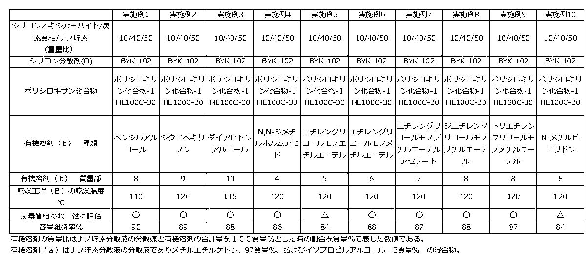


[評価方法]
表1から表3の中、ハンセン溶解度パラメータ、炭素質相の均一性および二次電池の容量維持率の評価方法は以下のとおりである。
表1から表3の中、ハンセン溶解度パラメータ、炭素質相の均一性および二次電池の容量維持率の評価方法は以下のとおりである。
ハンセン溶解度パラメータ
HSPiP 5thEditionを用いて有機溶剤のHSPを算出した。
炭素質相の均一性の評価
SEM-EDX:JSM-7800F(JEL製)を用いて測定した。炭素質相の大きさが2μm以上を×、1μm以下を△、0.5μm以下を〇とした。電池特性評価
二次電池充放電試験装置(北斗電工製)を用いて電池特性を測定した。室温25℃、カットオフ電圧範囲を0.005から1.5Vに設定し、充放電レートを1から3サイクルは0.1C、4サイクル以後は0.2Cとし、定電流・定電圧式充電/定電流式放電の設定条件下で充放電特性の評価試験を行った。各充放電時の切り替え時には、30分間、開回路で放置した。10サイクル時の容量維持率を下記式により求めた。容量維持率(10サイクル目)=10回目の放電容量(mAh/g)/初回放電容量(mAh/g)
HSPiP 5thEditionを用いて有機溶剤のHSPを算出した。
炭素質相の均一性の評価
SEM-EDX:JSM-7800F(JEL製)を用いて測定した。炭素質相の大きさが2μm以上を×、1μm以下を△、0.5μm以下を〇とした。電池特性評価
二次電池充放電試験装置(北斗電工製)を用いて電池特性を測定した。室温25℃、カットオフ電圧範囲を0.005から1.5Vに設定し、充放電レートを1から3サイクルは0.1C、4サイクル以後は0.2Cとし、定電流・定電圧式充電/定電流式放電の設定条件下で充放電特性の評価試験を行った。各充放電時の切り替え時には、30分間、開回路で放置した。10サイクル時の容量維持率を下記式により求めた。容量維持率(10サイクル目)=10回目の放電容量(mAh/g)/初回放電容量(mAh/g)
前記結果から明らかなように、本製造方法に得られる負極活物質は炭素質相の均一性に優れる。その結果、充放電によるリチウムイオンの挿入による珪素粒子の体積膨張を抑制され、容量維持率の高い二次電池を与える負極活物質が得られたと考えられる。本製造方法により、これら容量維持率に優れた二次電池を与える負極活物質および前記負極活物質を用いた二次電池が得られる。
Claims (8)
- 下記混合工程(A)、乾燥工程(B)および焼成工程(C)を含む負極活物質の製造方法。
混合工程(A):ナノ珪素分散液、ポリシロキサン化合物、炭素源樹脂および、前記ナノ珪素分散液または前記炭素源樹脂のいずれかが含有する有機溶剤(a)より高い沸点を有する有機溶剤(b)を混合し前駆体混合物を得る工程
乾燥工程(B):前記前駆体混合物を前記有溶剤(a)の沸点より高く前記有機溶剤(b)の沸点より低い温度で乾燥する工程
焼成工程(C):前記乾燥工程(B)で得られた乾燥物を不活性気体雰囲気中で高温焼成する工程 - 下記粉砕工程(D)をさらに含む請求項1に記載の負極活物質の製造方法。
粉砕工程(D):前記焼成工程(C)で得られた焼成物を粉砕する工程 - 前記混合工程(A)において、前記有機溶剤(b)の使用量が、前記ナノ珪素分散液、前記炭素源樹脂、前記ポリシロキサン化合物および前記有機溶剤(b)の総質量を100質量部として、4質量部以上である請求項1又は2に記載の負極活物質の製造方法。
- 前記混合工程(A)において、前記有機溶剤(b)の1気圧における沸点が110℃以上である請求項1又は2に記載の負極活物質の製造方法。
- 前記混合工程(A)において、前記有機溶剤(b)のハンセン溶解度パラメータにおけるδPが6MPa以上である、請求項1又は2に記載の負極活物質の製造方法。
- 前記混合工程(A)において、前記有機溶剤(b)のハンセン溶解度パラメータにおけるδHが5MPa以上、である、請求項1又は2に記載の負極活物質の製造方法。
- シリコンオキシカーバイド、珪素および炭素質相を有し、前記炭素質相の大きさが平均で2μm以下である負極活物質。
- 請求項7に記載の負極活物質を有する二次電池。
Priority Applications (1)
| Application Number | Priority Date | Filing Date | Title |
|---|---|---|---|
| JP2023537642A JP7435916B1 (ja) | 2022-05-11 | 2023-03-23 | 負極活物質の製造方法、負極活物質および二次電池 |
Applications Claiming Priority (2)
| Application Number | Priority Date | Filing Date | Title |
|---|---|---|---|
| JP2022-078176 | 2022-05-11 | ||
| JP2022078176 | 2022-05-11 |
Publications (1)
| Publication Number | Publication Date |
|---|---|
| WO2023218765A1 true WO2023218765A1 (ja) | 2023-11-16 |
Family
ID=88730029
Family Applications (1)
| Application Number | Title | Priority Date | Filing Date |
|---|---|---|---|
| PCT/JP2023/011354 Ceased WO2023218765A1 (ja) | 2022-05-11 | 2023-03-23 | 負極活物質の製造方法、負極活物質および二次電池 |
Country Status (2)
| Country | Link |
|---|---|
| JP (1) | JP7435916B1 (ja) |
| WO (1) | WO2023218765A1 (ja) |
Cited By (2)
| Publication number | Priority date | Publication date | Assignee | Title |
|---|---|---|---|---|
| WO2025158997A1 (ja) * | 2024-01-22 | 2025-07-31 | 株式会社ダイセル | 電極形成ペースト用溶剤組成物、電極形成用ペースト、電極の製造方法、および二次電池の製造方法 |
| WO2025225403A1 (ja) * | 2024-04-22 | 2025-10-30 | 株式会社ダイセル | 電極形成ペースト用溶剤組成物、電極形成用ペースト、電極の製造方法、および二次電池の製造方法 |
Families Citing this family (1)
| Publication number | Priority date | Publication date | Assignee | Title |
|---|---|---|---|---|
| WO2026004464A1 (ja) * | 2024-06-25 | 2026-01-02 | 日本特殊陶業株式会社 | キャパシタ及びその製造方法 |
Citations (4)
| Publication number | Priority date | Publication date | Assignee | Title |
|---|---|---|---|---|
| JP2012178224A (ja) * | 2011-01-31 | 2012-09-13 | Dow Corning Toray Co Ltd | 表面炭素被覆ケイ素含有炭素系複合材料の製造方法 |
| CN105552323A (zh) * | 2015-12-11 | 2016-05-04 | 中国科学院宁波材料技术与工程研究所 | 一种硅/碳氧化硅/碳负极材料及其制备方法和应用 |
| JP2016139579A (ja) * | 2015-01-29 | 2016-08-04 | 東レ株式会社 | リチウムイオン二次電池用負極材料、リチウムイオン二次電池負極用ペースト、リチウムイオン二次電池用負極およびリチウムイオン二次電池 |
| JP2021114483A (ja) * | 2018-12-19 | 2021-08-05 | Dic株式会社 | シリコンナノ粒子及びそれを用いた非水二次電池負極用活物質並びに二次電池 |
-
2023
- 2023-03-23 JP JP2023537642A patent/JP7435916B1/ja active Active
- 2023-03-23 WO PCT/JP2023/011354 patent/WO2023218765A1/ja not_active Ceased
Patent Citations (4)
| Publication number | Priority date | Publication date | Assignee | Title |
|---|---|---|---|---|
| JP2012178224A (ja) * | 2011-01-31 | 2012-09-13 | Dow Corning Toray Co Ltd | 表面炭素被覆ケイ素含有炭素系複合材料の製造方法 |
| JP2016139579A (ja) * | 2015-01-29 | 2016-08-04 | 東レ株式会社 | リチウムイオン二次電池用負極材料、リチウムイオン二次電池負極用ペースト、リチウムイオン二次電池用負極およびリチウムイオン二次電池 |
| CN105552323A (zh) * | 2015-12-11 | 2016-05-04 | 中国科学院宁波材料技术与工程研究所 | 一种硅/碳氧化硅/碳负极材料及其制备方法和应用 |
| JP2021114483A (ja) * | 2018-12-19 | 2021-08-05 | Dic株式会社 | シリコンナノ粒子及びそれを用いた非水二次電池負極用活物質並びに二次電池 |
Cited By (2)
| Publication number | Priority date | Publication date | Assignee | Title |
|---|---|---|---|---|
| WO2025158997A1 (ja) * | 2024-01-22 | 2025-07-31 | 株式会社ダイセル | 電極形成ペースト用溶剤組成物、電極形成用ペースト、電極の製造方法、および二次電池の製造方法 |
| WO2025225403A1 (ja) * | 2024-04-22 | 2025-10-30 | 株式会社ダイセル | 電極形成ペースト用溶剤組成物、電極形成用ペースト、電極の製造方法、および二次電池の製造方法 |
Also Published As
| Publication number | Publication date |
|---|---|
| JPWO2023218765A1 (ja) | 2023-11-16 |
| JP7435916B1 (ja) | 2024-02-21 |
Similar Documents
| Publication | Publication Date | Title |
|---|---|---|
| JP7447865B2 (ja) | シリコンナノ粒子及びそれを用いた非水二次電池負極用活物質並びに二次電池 | |
| JP7343081B2 (ja) | 二次電池用材料、負極活物質および二次電池 | |
| JP7435916B1 (ja) | 負極活物質の製造方法、負極活物質および二次電池 | |
| JP7323089B1 (ja) | 負極活物質、二次電池および負極活物質の製造方法 | |
| JP7586255B2 (ja) | 二次電池用複合活物質および二次電池 | |
| JP7485230B2 (ja) | ナノシリコン、ナノシリコンスラリー、ナノシリコンの製造方法、二次電池用活物質および二次電池 | |
| JP7424555B1 (ja) | 負極活物質および二次電池 | |
| EP4102596A1 (en) | Low oxygen-type silicon nanoparticle-containing slurry, negative electrode active material, negative electrode and lithium ion secondary battery | |
| JP7453631B2 (ja) | ケイ素系材料、ケイ素系材料を含む複合材料、二次電池用負極物質および二次電池 | |
| JP7491478B2 (ja) | 二次電池用活物質および二次電池 | |
| JP7491482B2 (ja) | 二次電池用活物質、二次電池用活物質の製造方法および二次電池 | |
| JP7473098B1 (ja) | 負極活物質前駆体、負極活物質、二次電池および負極活物質の製造方法 | |
| JP2025008898A (ja) | シリコン粒子、シリコン含有活物質、二次電池用負極活物質、負極および二次電池 | |
| JP2025008899A (ja) | シリコン粒子、シリコン含有活物質、二次電池用負極活物質、負極および二次電池 | |
| JP2025008900A (ja) | シリコン粒子、シリコン含有活物質、二次電池用負極活物質、負極および二次電池 | |
| JP2025147581A (ja) | 負極活物質及びその製造方法、並びに二次電池 | |
| JP2025010003A (ja) | ナノシリコン、ナノシリコン含有スラリー、二次電池用活物質、ナノシリコン含有スラリーの製造方法、及び二次電池用活物質の製造方法 | |
| WO2024048051A1 (ja) | 負極活物質および二次電池 |
Legal Events
| Date | Code | Title | Description |
|---|---|---|---|
| ENP | Entry into the national phase |
Ref document number: 2023537642 Country of ref document: JP Kind code of ref document: A |
|
| 121 | Ep: the epo has been informed by wipo that ep was designated in this application |
Ref document number: 23803248 Country of ref document: EP Kind code of ref document: A1 |
|
| NENP | Non-entry into the national phase |
Ref country code: DE |
|
| 122 | Ep: pct application non-entry in european phase |
Ref document number: 23803248 Country of ref document: EP Kind code of ref document: A1 |