WO2023218624A1 - 前照灯装置 - Google Patents
前照灯装置 Download PDFInfo
- Publication number
- WO2023218624A1 WO2023218624A1 PCT/JP2022/020161 JP2022020161W WO2023218624A1 WO 2023218624 A1 WO2023218624 A1 WO 2023218624A1 JP 2022020161 W JP2022020161 W JP 2022020161W WO 2023218624 A1 WO2023218624 A1 WO 2023218624A1
- Authority
- WO
- WIPO (PCT)
- Prior art keywords
- light
- light source
- incident
- optical member
- projection optical
- Prior art date
- Legal status (The legal status is an assumption and is not a legal conclusion. Google has not performed a legal analysis and makes no representation as to the accuracy of the status listed.)
- Ceased
Links
Images


Classifications
-
- F—MECHANICAL ENGINEERING; LIGHTING; HEATING; WEAPONS; BLASTING
- F21—LIGHTING
- F21S—NON-PORTABLE LIGHTING DEVICES; SYSTEMS THEREOF; VEHICLE LIGHTING DEVICES SPECIALLY ADAPTED FOR VEHICLE EXTERIORS
- F21S41/00—Illuminating devices specially adapted for vehicle exteriors, e.g. headlamps
- F21S41/20—Illuminating devices specially adapted for vehicle exteriors, e.g. headlamps characterised by refractors, transparent cover plates, light guides or filters
- F21S41/25—Projection lenses
- F21S41/27—Thick lenses
Definitions
- the present disclosure relates to a headlamp device having low beam and high beam functions.
- a headlamp device that includes a low beam light source and a high beam light source is known.
- the headlamp device disclosed in Patent Document 1 includes a projection lens, a low beam light source, a high beam light source, a reflector, and a shade.
- the reflector reflects the light emitted from the low beam light source toward the projection lens.
- the light reflected by the reflector is reflected by the top surface of the shade and enters the projection lens. At that time, part of the light is blocked by the shade to form a cut-off line. Furthermore, the light emitted from the high beam light source is reflected by the lower surface of the shade and enters the projection lens.
- the projection lens, reflector, and shade are each configured as separate members. Therefore, if the relative positional accuracy of each member decreases due to assembly errors, light that is not captured by the reflector or projection lens is generated, resulting in a decrease in light utilization efficiency. This problem becomes more prominent as headlamp devices become smaller.
- the present disclosure has been made to solve the above-mentioned problems, and aims to provide a headlamp device that can emit low beams and high beams, has high light utilization efficiency, and is suitable for downsizing.
- the headlamp device of the present disclosure includes a first light source for low beam, a second light source for high beam, and the light emitted from the first light source and the light emitted from the second light source enter, and a projection optical member that emits these lights from an output surface.
- the projection optical member has a first entrance surface into which light enters from a first light source, a second entrance surface into which light enters from a second light source, and an exit surface through which light enters from the first entrance surface. It has a first reflective surface that reflects light toward the output surface, and a second reflective surface that reflects light incident from the second incident surface toward the output surface.
- the second entrance surface has a light condensing section.
- a headlamp device that is capable of emitting low beam and high beam, has high light utilization efficiency, and is suitable for downsizing.
- FIG. 1 is a side view showing the configuration of a headlamp device according to Embodiment 1.
- FIG. FIG. 2 is a rear view showing the configuration of the headlamp device according to the first embodiment.
- (A) and (B) are side views showing a configuration example of a condensing optical element according to Embodiment 1.
- FIG. FIG. 3 is a side view showing a projection optical member of the headlamp device according to the first embodiment.
- (A) and (B) are diagrams showing a portion of the projection optical member of Embodiment 1 including a high beam light entrance surface.
- 1 is a diagram showing a light distribution pattern for a motorcycle formed by the headlamp device of Embodiment 1.
- FIG. 2 is a rear view showing an example of the headlamp device according to the first embodiment, which includes a cut-off line forming section that forms a light distribution pattern for a four-wheeled vehicle.
- 8 is a diagram showing a light distribution pattern for a four-wheeled vehicle formed by the headlamp device of FIG. 7.
- FIG. It is a side view which shows the projection optical member of a modification.
- FIG. 3 is a side view showing the configuration of a headlamp device according to a second embodiment.
- FIG. 7 is a diagram showing a portion of a projection optical member according to Embodiment 2, including a high beam light entrance surface.
- FIG. 7 is a diagram showing optical paths for low beam and high beam in the projection optical member according to the second embodiment.
- FIG. 7 is a perspective view showing a high beam light source and an incident surface of a projection optical member according to a second embodiment.
- FIG. 3 is a diagram showing an example of the shape of the output surface of the projection optical member of Embodiments 1 and 2.
- FIG. 2 is a side view showing an example of a mounting structure for a light source according to Embodiments 1 and 2.
- FIG. 2 is a side view showing an example of a projection optical member according to Embodiments 1 and 2.
- Light distribution refers to the luminous intensity distribution of a light source in space. In other words, light distribution is the spatial distribution of light emitted from a light source. Moreover, “luminous intensity” indicates the degree of intensity of light emitted by a light emitter. Luminous intensity is the luminous flux passing within a small solid angle in a certain direction divided by that solid angle.
- Light distribution pattern refers to the shape of a luminous flux and the intensity distribution of light caused by the direction of light emitted from a light source.
- Light distribution pattern is also used to mean an illuminance distribution pattern on an irradiation surface.
- Illuminance is a physical quantity representing the brightness of light irradiated onto a planar object, and is equal to the luminous flux irradiated per unit area.
- the light distribution pattern specified for automobile low beams in the Road Traffic Regulations has a horizontally long shape that is narrow in the vertical direction.
- the cutoff line which is the upper boundary line of the light distribution pattern, is required to be clear. In other words, it is required that the area above the cut-off line (ie, outside the light distribution pattern) is dark and the area below the cut-off line (ie, inside the light distribution pattern) is bright, that is, the cut-off line is clear.
- the "cutoff line” refers to the dividing line between bright and dark light that is created when the light emitted from the headlight device is irradiated onto a wall or screen, and is the dividing line at the top of the light distribution pattern. be.
- the "cutoff line” is the boundary line between bright and dark light above the light distribution pattern.
- the cut-off line is a boundary line between an upper bright area within the light distribution pattern and a dark area outside the light distribution pattern.
- the cut-off line is a term used to describe the function of adjusting the direction of light emitted from the headlight device when vehicles pass each other.
- the area below the cut-off line that is, the area inside the light distribution pattern and slightly below the cut-off line, is required to be the area of maximum illuminance.
- This area of maximum illuminance is called a "high illuminance area.”
- the "region below the cut-off line” means the upper region in the light distribution pattern, and corresponds to the part of the headlamp device that illuminates a distant area. In order to realize such a clear cut-off line, it is desirable that the cut-off line does not have large chromatic aberrations or blurring. "The cut-off line becomes blurred" means that the cut-off line becomes unclear.
- the shape of the cut-off line is determined by the laws and regulations of each country. Generally, in a low beam of a headlamp device for an automobile, the cutoff line has a stepped shape with a rising line.
- headlight device since the headlight device is placed on the front of the vehicle, design is important. In particular, many conventional headlight devices have circular openings, but there is a demand for headlight devices with even greater freedom in design. For example, a headlamp device having an elongated opening (i.e., an exit surface for emitting light) in the vertical direction of the vehicle has rarely been seen to date, and is thought to be able to enhance the design.
- an elongated opening i.e., an exit surface for emitting light
- the headlight device of the present disclosure is applied to a low beam or high beam of a vehicle headlight device. Further, the headlight device of the present disclosure is also applied to a low beam or high beam of a headlight device for a motorcycle. Furthermore, the headlight device of the present disclosure is also applied to low beams or high beams of headlight devices of other vehicles such as three-wheeled or four-wheeled vehicles.
- the cutoff line extends in the left-right direction of the vehicle, and the area inside the light distribution pattern and slightly below the cutoff line is the brightest.
- the light distribution pattern of the low beam of the headlight for four-wheeled vehicles has multiple steps in the light distribution pattern, taking into consideration the glare given to oncoming vehicles and vehicles in front. Commission for Europe).
- the high beam of the headlights extends in the left and right directions of the vehicle, and is the brightest in the central area of the horizon. This is the same for both motorcycles and automobiles.
- the high beam of the headlight uses multiple light sources or multiple headlight modules to selectively and dynamically illuminate multiple locations.
- the headlamp device according to the present disclosure can also be applied to a headlamp device for such uses.
- a three-wheeled vehicle is an automatic tricycle called a gyro.
- a ⁇ gyro tricycle'' is a three-wheeled scooter with one front wheel and one rear wheel with two wheels.
- tricycles are classified as motorized bicycles.
- a tricycle has a rotation axis near the center of the vehicle body, and most of the vehicle body, including the front wheels and driver's seat, can be tilted left and right. This mechanism allows a tricycle, like a motorcycle, to move its center of gravity inward when turning.
- the left and right direction of the vehicle is defined as the X-axis direction.
- the right side when facing the front of the vehicle is the +X-axis direction, and the left side when facing the front of the vehicle is the -X-axis direction.
- “Front” refers to the direction in which the vehicle moves forward. In other words, "forward” is the direction in which the headlights emit light.
- the vertical direction of the vehicle is defined as the Y-axis direction.
- the upper side is the +Y-axis direction
- the lower side is the -Y-axis direction.
- the traveling direction of the vehicle is assumed to be the Z-axis direction.
- the direction in which the vehicle moves forward is defined as the +Z-axis direction, and the opposite direction is defined as the -Z-axis direction.
- the +Z-axis direction is called the "front” direction, and the -Z-axis direction is called the "backward” direction.
- the +Z-axis direction is a direction in which a headlamp device mounted on a vehicle irradiates light.
- the ZX plane is a plane parallel to the road surface. Normally, a road surface can be considered a “horizontal surface.” For this reason, the ZX plane is also called a “horizontal plane.”
- a “horizontal plane” is a plane perpendicular to the direction of gravity.
- the road surface may be inclined with respect to the direction in which the vehicle is traveling. That is, when going uphill or downhill, the road surface is inclined with respect to the horizontal plane. In these cases, the "horizontal plane” is considered to be a plane parallel to the road surface. In other words, in this case, the "horizontal plane” is not considered to be a plane perpendicular to the direction of gravity.
- the "horizontal plane” is considered to be a plane perpendicular to the direction of gravity.
- the vehicle is perpendicular to the left-right direction of the road surface, this is considered to be equivalent to a state in which the vehicle is tilted in the left-right direction with respect to a "horizontal plane.”
- a "horizontal plane” is assumed to be a plane perpendicular to the direction of gravity. That is, the ZX plane will be explained assuming that the plane perpendicular to the direction of gravity is a plane.
- FIG. 1 is a side view showing a configuration example of a headlamp device 100 according to the first embodiment.
- FIG. 2 is a diagram of the headlamp device 100 of the first embodiment viewed from the ⁇ Z-axis side, that is, a rear view.
- the headlamp device 100 is a device for a vehicle.
- a headlamp device 100 according to the first embodiment includes a low beam light source 1 as a first light source, a high beam light source 2 as a second light source, and a projection optical member 3.
- the light source 1 may be a lamp light source such as an incandescent lamp, a halogen lamp, or a fluorescent lamp, or may be a semiconductor light source such as a light emitting diode (LED) or a laser diode (LD). Good too.
- a semiconductor light source is desirable from the viewpoint of reducing the burden on the environment by suppressing carbon dioxide (CO 2 ) emissions and fuel consumption.
- Semiconductor light sources are also desirable from the viewpoint of higher luminous efficiency than lamp light sources. Further, semiconductor light sources are desirable from the viewpoint of having higher directivity than lamp light sources and allowing the optical system to be made smaller and lighter.
- the light source 1 is located above the optical axis C3 of the projection optical member 3 (that is, in the +Y-axis direction).
- the light source 1 emits low beam light as first light.
- the light source 1 emits low beam light toward the projection optical member 3.
- the optical axis C1 of the light source 1 is inclined at an angle ⁇ with respect to the Y-axis direction.
- the headlamp device 100 has one light source 1.
- the headlamp device 100 may have a plurality of light sources 1 lined up in the X-axis direction.
- the light source 2 may be a lamp light source such as an incandescent lamp, a halogen lamp, or a fluorescent lamp, or may be a semiconductor light source such as an LED or LD.
- a semiconductor light source is desirable from the viewpoint of reducing the load on the environment. Semiconductor light sources are desirable because they have higher luminous efficiency than lamp light sources, and they are also desirable because they have higher directivity than lamp light sources and can make the optical system smaller and lighter.
- the light source 2 is located below the light source 1 (ie, in the ⁇ Y-axis direction). Further, the light source 2 is located below the optical axis C3 of the projection optical member 3. The light source 2 emits high beam light as second light. The light source 2 emits high beam light toward the projection optical member 3.
- the optical axis C2 of the light source 2 is inclined at an angle ⁇ with respect to the Y-axis direction.
- a plurality of light sources 2 are arranged in the X-axis direction. Each light source 2 can be turned on individually. The number of light sources 2 is 17 here. However, the number of light sources 2 may be greater or less than 17. Further, these light sources 2 are mounted on a substrate 21. The plurality of light sources 2 arranged in the X-axis direction are collectively referred to as a light source section 20.
- the headlamp device 100 may include a condensing optical element 12 as a condensing optical system.
- the condensing optical element 12 is an optical element having a condensing function, and condenses the light emitted from the light source 1 onto a reflecting surface 33 of the projection optical member 3, which will be described later. Thereby, the light emitted isotropically from the light source 1 can be efficiently used, and the light usage efficiency of the headlamp device 100 is improved.
- the condensing optical element 12 is made of, for example, transparent resin, light-transmitting glass, or silicone material.
- the material of the condensing optical element 12 is preferably a material with high light transmittance. Furthermore, since the condensing optical element 12 is placed immediately after the light source 1, a material with excellent heat resistance is preferable.
- FIG. 3(A) is a diagram showing an example of the configuration of the condensing optical element 12.
- the condensing optical element 12 shown in FIG. 3(A) has an incident surface 12a, an incident surface 12b, a reflective surface 12c, an output surface 12d, and an output surface 12e.
- the condensing optical element 12 is arranged on the output side of the light source 1, that is, on the side from which light is emitted from the light source 1.
- the optical axis of the condensing optical element 12 is common to the optical axis C1 of the light source 1.
- the condensing optical element 12 an X 1 Y 1 Z 1 orthogonal coordinate system, which is different from the XYZ orthogonal coordinate system, will be used for easy understanding.
- the X 1 Y 1 Z 1 orthogonal coordinate system is a coordinate system in which the XYZ orthogonal coordinate system is viewed from the +X-axis side and rotated clockwise by an angle ⁇ (FIG. 1) about the X-axis as the rotation center.
- the optical axis C1 of the condensing optical element 12 is parallel to the Z1 axis.
- the entrance surfaces 12a and 12b are arranged at positions where the light from the light source 1 enters.
- the entrance surface 12a has the shape of a rotating body centered on the optical axis C1.
- the entrance surface 12a has, for example, a circular cross-sectional shape perpendicular to the optical axis C1, and a cylindrical shape in which the diameter of the circle decreases in the +Z 1- axis direction.
- the entrance surface 12a has positive power.
- the entrance surface 12b is connected to the inner periphery of the end of the entrance surface 12a in the +Z 1- axis direction, and is located on the optical axis C1.
- the entrance surface 12b is a curved surface that is convex in the -Z uniaxial direction and has positive power.
- light rays with a large emission angle are incident on the incident surface 12a, and light rays with a small emission angle are incident on the incident surface 12b.
- the reflective surface 12c is arranged closer to the outer circumference than the incident surfaces 12a and 12b.
- the reflective surface 12c extends further in the +Z 1- axis direction from the end of the entrance surface 12a in the -Z 1- axis direction than the end of the entrance surface 12a in the +Z 1- axis direction. That is, the reflective surface 12c is arranged at a position where the light refracted by the incident surface 12a enters.
- the reflective surface 12c has, for example, a circular cross-sectional shape perpendicular to the optical axis C1, and a cylindrical shape in which the diameter of the circle increases in the + Z direction.
- the reflective surface 12c has positive power.
- the output surface 12d is connected to the end of the reflection surface 12c in the +Z 1- axis direction.
- the output surface 12d is a plane perpendicular to the optical axis C1.
- the output surface 12d has, for example, an annular shape centered on the optical axis C1.
- the output surface 12e is arranged on the optical axis C1.
- the exit surface 12e is a curved surface that is convex in the +Z uniaxial direction and has positive power.
- the outer periphery of the output surface 12e has, for example, a circular shape, and is connected to the inner periphery of the output surface 12d.
- the light rays with a large emission angle are incident on the incident surface 12a, and the light rays with a small emission angle are incident on the incident surface 12b.
- the light ray R11 is refracted by the incident surface 12a, moves toward the reflective surface 12c, is reflected by the reflective surface 12c, and then exits from the output surface 12d.
- the light ray R12 undergoes a refraction action at the entrance surface 12b, heads toward the exit surface 12e, and is emitted from the exit surface 12e.
- the light emitted from the light source 1 can be focused within the projection optical member 3, which will be described below.
- the shapes of the incident surfaces 12a, 12b, the reflective surface 12c, and the exit surfaces 12d, 12e have been specifically described, but the shapes described here are just examples, and are not limited to these shapes.
- the surface shape of the output surface 12d may be a curved surface having positive power.
- the entrance surface 12a, the entrance surface 12b, the reflection surface 12c, and the exit surface 12e are curved surfaces with positive power, they may be flat surfaces or curved surfaces with negative power.
- the condensing optical element 120 shown in FIG. 3(B) may be used instead of the condensing optical element 12 shown in FIG. 3(A).
- the condensing optical element 120 shown in FIG. 3(B) is composed of an optical lens having positive power.
- the condensing optical element 120 has an entrance surface 121 and an exit surface 122.
- the entrance surface 121 is composed of a curved surface that is convex in the -Z 1- axis direction
- the exit surface 122 is composed of a curved surface that is convex in the +Z 1- axis direction.
- the center of the entrance surface 121 and the center of the exit surface 122 are located on the optical axis C1.
- the condensing optical element 120 By configuring the condensing optical element 120 with an optical lens having positive power, the light emitted from the light source 1 can be condensed and emitted.
- the light beam emitted from the condensing optical element 120 is referred to as a light beam R13.
- the condensing optical element 120 is here constructed of a single optical lens having positive power, it may be constructed of a plurality of optical members combined so that the sum of each optical member has positive power. .
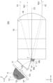
- FIG. 4 is a side view showing the light source 1, light source 2, condensing optical element 12, and projection optical member 3 of the first embodiment. As shown in FIG. 4, the light emitted from the light sources 1 and 2 enters the projection optical member 3. The projection optical member 3 emits the incident light forward (ie, in the +Z-axis direction). Further, the projection optical member 3 has a function of emitting the guided light as illumination light to be described later.
- the projection optical member 3 is made of, for example, transparent resin, light-transmissive glass, or silicone material. Further, the projection optical member 3 of the first embodiment has an interior filled with a light-transmitting refractive material, for example. In order to improve the light utilization efficiency, the material of the projection optical member 3 is preferably a material with high light transmittance. Further, since the projection optical member 3 is disposed immediately after the light source 2, a material with excellent heat resistance is preferably used.
- the projection optical member 3 includes an entrance surface 31 as a first entrance surface, an entrance surface 32 as a second entrance surface, a reflection surface 33 as a first reflection surface, and a reflection surface 33 as a second reflection surface. It has a surface 34, a cut-off line forming part 35, and an output surface 36.
- the entrance surface 31 as a first entrance surface is located in the +Z 1- axis direction of the condensing optical element 12 and faces the output surfaces 12d and 12e of the condensing optical element 12. That is, the entrance surface 31 is formed at a position where the light ray R1 emitted from the low beam light source 1 and passed through the condensing optical element 12 is incident.
- the light ray R1 is a combination of the light rays R11 and R12 shown in FIG. 3(A), or the light ray R13 shown in FIG. 3(B).
- the incident surface 31 is, for example, a plane perpendicular to the optical axis C1 of the light source 1.
- the entrance surface 31 may be formed of a curved surface.
- the entrance surface 31 is also located above the optical axis C3 of the projection optical member 3 (that is, in the +Y-axis direction).
- the entrance surface 32 as a second entrance surface is arranged to face the high beam light source 2.
- the entrance surface 32 is formed on the optical axis C2 of the light source 2. That is, the entrance surface 32 is formed at a position where the light ray R2 emitted from the light source 2 is incident.
- the entrance surface 32 is also located below the optical axis C3 of the projection optical member 3 (that is, in the ⁇ Y-axis direction). Further, a rear end portion of the incident surface 32 (that is, an end portion in the ⁇ Z-axis direction) and a rear end portion of a reflecting surface 34, which will be described later, are connected by a ridgeline E.
- the high beam of the headlamp device 100 is required to have high luminous intensity in order to brightly illuminate a distant area. Therefore, it is desirable to efficiently condense the light emitted from the light source 2 toward the reflective surface 34.
- FIG. 5(A) is a diagram showing the light source 2 and a portion of the projection optical member 3 including the entrance surface 32.
- the entrance surface 32 is composed of a curved surface having positive power. More specifically, the entrance surface 32 is formed of a curved surface that is convex toward the light source 2 side.
- the light ray R2 incident from the light source 2 is incident on the incident surface 32.
- the incident surface 32 condenses the incident light ray R2 toward the reflective surface 34.
- the entrance surface 32 has the function of condensing the light from the light source 2.
- the entrance surface 32 has a light condensing section. Due to the light condensing effect of the incident surface 32, more high beam light can be collected on the reflective surface 34, and a light distribution pattern with high luminous intensity can be formed.
- the entrance surface 32 is a curved surface that is convex toward the light source 2 side here, it is not limited to such a configuration and may have a positive power.
- the incident surface 32 is also referred to as a light condensing surface or a light condensing section.
- the reflective surface 33 as the first reflective surface is located below the incident surface 31 (ie, in the ⁇ Y-axis direction).
- the lower end of the reflective surface 33 ie, the end in the -Z-axis direction
- the reflective surface 33 reflects the light from the incident surface 31 forward (that is, in the +Z-axis direction) toward the exit surface 36 .
- the reflective surface 33 is a surface that generally faces the +Y-axis direction.
- the reflective surface 33 is a surface inclined at an angle ⁇ with respect to the ZX plane.
- the angle ⁇ may be 0 degrees, but is preferably larger than 0 degrees from the viewpoint of improving light utilization efficiency.
- the reflective surface 33 is shown as a plane in FIG. However, the reflective surface 33 is not limited to a flat surface, and may have a curved shape or a polyhedral shape in which a plurality of planes are connected.
- the reflective surface 34 as the second reflective surface is arranged below and adjacent to the reflective surface 33 (ie, in the ⁇ Y-axis direction).
- the reflective surface 34 is located at a position where the light incident from the incident surface 32 is incident.
- a cut-off line forming portion 35 is formed between the reflective surface 33 and the reflective surface 34.
- the reflective surface 34 is arranged above the incident surface 32 (that is, in the +Y-axis direction).
- a ridgeline E is formed between the reflective surface 34 and the incident surface 32.
- the configuration is not limited to this, and the reflective surface 34 and the incident surface 32 may be separated.
- the reflective surface 34 reflects the light from the incident surface 32 forward.
- the reflective surface 34 is a surface that generally faces the +Y-axis direction.
- the reflective surface 34 is a surface inclined at an angle ⁇ with respect to the ZX plane.
- the angle ⁇ may be 0 degrees, but from the viewpoint of improving light utilization efficiency, it is preferably larger than 0 degrees.
- Both of these reflective surfaces 33 and 34 may be mirror surfaces formed by mirror vapor deposition using metal or the like, but it is desirable that they function as total reflection surfaces without mirror vapor deposition. This is because the total reflection surface has a higher reflectance than the mirror surface and contributes to improving the light utilization efficiency. Further, by eliminating the mirror vapor deposition process, the manufacturing process of the projection optical member 3 can be simplified and manufacturing costs can be reduced. In the first embodiment, since the angle of incidence of the light rays on the reflective surfaces 33 and 34 is large, the reflective surfaces 33 and 34 can be made into total reflection surfaces without mirror deposition.
- the reflecting surface 34 that reflects the light incident from the incident surface 32 is shown as a flat surface in FIGS. 4 and 5(A), it may be a curved surface.
- a reflective surface 34A formed of a curved surface having positive power may be used.
- the cut-off line forming portion 35 is a ridgeline formed between the reflective surface 33 and the reflective surface 34.
- the cut-off line forming portion 35 is configured of a straight line extending in the X-axis direction. Further, the cut-off line forming portion 35 is located close to the focal point F of the output surface 36 in the Z-axis direction. Therefore, the illuminance distribution formed by each of the light sources 1 and 2 on the cut-off line forming section 35 is inverted and projected by the output surface 36, and becomes the light distribution pattern of the headlamp device 100.
- the output surface 36 is provided at the end of the projection optical member 3 in the +Z-axis direction.
- the exit surface 36 is a curved surface having positive power. More specifically, the output surface 36 is a curved surface that is convex in the +Z-axis direction.
- the output surface 36 outputs the light rays R1 and R2 reflected by the reflection surfaces 33 and 34 to the irradiation surface 4 in front (that is, in the +Z-axis direction).
- the optical axis C3 of the projection optical member 3 is a normal line passing through the surface apex of the output surface 36, and is parallel to the Z-axis here.
- the irradiation surface 4 (FIG. 1) is a virtual surface set at a prescribed position in front of the vehicle.
- the irradiation surface 4 is a surface parallel to the XY plane, that is, a vertical surface.
- the specified position in front of the vehicle is a position where the luminous intensity or illuminance of the headlamp device is measured, and is specified by road traffic regulations.
- the measurement position of the luminous intensity of an automobile headlamp device defined by the United Nations Economic Commission for Europe (UNECE) is a position 25 meters from the light source.
- the light intensity measurement position specified by Japan Industrial Standards Committee (JIS) in Japan is 10 m from the light source.
- the distance from the headlamp device 100 to the irradiation surface 4 is shown short for convenience of illustration, but the actual distance from the headlamp device 100 to the irradiation surface 4 is shorter than that shown in FIG. It's also long.
- the light beam emitted from below the optical axis C3 of the emission surface 36 is irradiated upward on the irradiation surface 4.
- the light beam emitted from above the optical axis C3 of the emission surface 36 is irradiated downward on the irradiation surface 4.
- the low beam light R1 emitted from the light source 1 enters the entrance surface 31 of the projection optical member 3, is reflected forward by the reflection surface 33, and is reflected forward by the exit surface 36.
- the irradiation surface 4 is irradiated from the irradiation surface 4.
- the high beam light R2 emitted from the light source 2 enters the entrance surface 32 of the projection optical member 3, is reflected forward by the reflection surface 34, and is irradiated onto the irradiation surface 4 from the exit surface 36.
- the projection optical member 3 integrally includes the incident surfaces 31 and 32, the reflective surfaces 33 and 34, and the output surface 36, so that the relative positions of each part are maintained with high precision. Ru. Therefore, the generation of stray light due to assembly errors can be suppressed, and light utilization efficiency can be improved.
- the utilization efficiency of the high beam light emitted from the light source 2 is improved, and the high beam A high luminous intensity can be obtained.
- the condensing optical element 12 by condensing the light emitted from the light source 1 toward the reflective surface 33 by the condensing optical element 12, the utilization efficiency of the low beam light emitted from the light source 1 is improved, and the low beam has high luminous intensity. can be obtained.
- the entrance surface 32 of the projection optical member 3 exhibits a light condensing effect, there is no need to arrange a condensing element as a separate member between the light source 2 and the projection optical member 3. Therefore, there is no need to increase the number of parts, and it is possible to downsize the headlamp device 100 and reduce manufacturing costs.
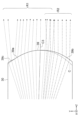
- FIG. 6 is a diagram showing a light distribution pattern 40 formed on the irradiation surface 4 by the headlamp device 100.
- the H line and the V line are straight lines passing through the HV point defined by the regulations regarding headlamp devices.
- the HV point is the intersection of the irradiation surface 4 and the optical axis C3 of the projection optical member 3.
- the H line is a straight line in the horizontal direction, and is also called a horizontal line.
- the V line is a straight line in the vertical direction, and is also called a vertical line.
- a light distribution pattern 41 for low beam is formed on the irradiation surface 4 by the light ray R1 emitted from the light source 1 for low beam, passed through the condensing optical element 12, the incident surface 31, and the reflective surface 33, and exited from the output surface 36. be done.
- a cut-off line CL is formed in the light distribution pattern 41 by the cut-off line forming section 35 .
- a light distribution pattern 42 for high beam is formed on the irradiation surface 4 by the light ray R2 emitted from the light source 2 for high beam, passed through the incident surface 32 and the reflective surface 33, and exited from the exit surface 36.
- the light distribution pattern 42 for high beam is located above the light distribution pattern 41 for low beam.
- the light distribution pattern 42 is a light distribution pattern 421 in which the image of the light source 2 is enlarged and projected and arranged in the X-axis direction.
- the cut-off line forming portion 35 is formed as a ridgeline between the reflective surface 33 and the reflective surface 34, but is not limited to this.
- the reflective surface 33 and the reflective surface 34 may be formed apart from each other.
- the above-mentioned headlamp device regulations require higher illuminance values around the cut-off line of the light distribution pattern. It is particularly desirable to form the cut-off line forming portion 35 as a ridge line between the reflective surface 33 and the reflective surface 34 because the illuminance value around the cut-off line of the light distribution pattern can be increased.
- a light distribution pattern having a straight cut-off line in the horizontal direction is mainly suitable for light distribution for motorcycles.
- a light distribution pattern having a stepped shape at the cut-off line is desirable from the viewpoint of legal compliance of the headlamp device.
- FIG. 7 is a view of the headlamp device 100 having the cut-off line forming section 37 that forms a light distribution pattern for a four-wheeled vehicle as viewed from the ⁇ Z-axis side, that is, a rear view.
- the cutoff line forming portion 37 has a stepped shape including a ridgeline portion 37a, a ridgeline portion 37b, and a ridgeline portion 37c.
- the ridgeline portions 37a, 37b, and 37c are located at the end in the +X-axis direction, the center in the X-axis direction, and the end in the -X-axis direction. Moreover, among the ridgeline parts 37a, 37b, and 37c, the height of the ridgeline part 37a (that is, the position in the Y-axis direction) is the lowest, and the height of the ridgeline part 37b is the highest. Further, the ridgeline portion 37a and the ridgeline portion 37b are connected via an inclined portion, and the ridgeline portion 37b and the ridgeline portion 37c are connected via an inclined portion.
- FIG. 8 is a diagram showing a light distribution pattern 40 formed on the irradiation surface 4 by the headlamp device 100 shown in FIG. 7.
- the stepped shape of the cut-off line forming portion 37 is inverted and projected. Therefore, the cut-off line CL of the light distribution pattern formed on the irradiation surface 4 has line portions CL1, CL2, and CL3 facing the ridge portions 37a, 37b, and 37c.
- Line portion CL1 is formed at a step lower than line portion CL3.
- Line portion CL1 is located on the opposite lane side, and line portion CL3 is located on the own lane side.
- the shape of the cutoff line CL shown in FIG. 8 is just an example. Depending on the uneven shape of the cut-off line forming portion 37, a light distribution pattern having a cut-off line CL having a desired uneven shape can be obtained.
- the headlamp device 100 of the first embodiment includes a light source 1 that emits low beam light, a light source 2 that emits high beam light, and projects light from the light sources 1 and 2. and a projection optical member 3.
- the projection optical member 3 includes an entrance surface 31 on which the light from the light source 1 enters, an entrance surface 32 on which the light from the light source 2 enters, a reflective surface 33 that reflects the light that entered from the entrance surface 31, and an entrance surface 32. It has a reflective surface 34 that reflects the light incident thereon, and an output surface 36 that emits the light reflected by the reflective surface 33 and the light reflected by the reflective surface 34.
- the projection optical member 3 has an entrance surface 31, an entrance surface 32, a reflection surface 33, a reflection surface 34, and an exit surface 36, the mutual positional accuracy of each part can be maintained, and the generation of stray light can be suppressed to achieve a high Light usage efficiency can be achieved. Further, even when the headlamp device 100 is downsized, the mutual positional accuracy of each part of the projection optical member 3 is maintained, and high light utilization efficiency can be obtained. That is, it is possible to realize a headlamp device 100 that can emit low beams and high beams, has high light utilization efficiency, and is suitable for downsizing.
- the entrance surface 32 of the projection optical member 3 has a light condensing section (that is, it has the function of condensing light), it is possible to improve the efficiency of high beam light use without increasing the number of parts, and to improve the high beam light utilization efficiency. High luminous intensity can be obtained.
- the headlamp device 100 includes the projection optical member 3 and the condensing optical element 12 separately.
- the projection optical member 3 and the condensing optical element 12 may be integrally configured.
- FIG. 9 shows a projection optical member 3A that is integrally equipped with a condensing section 301 that has the function of condensing the light emitted from the light source 1.
- the projection optical member 3A has a light condensing section 301 having incident surfaces 12a, 12b and a reflecting surface 12c.
- the projection optical member 30 also has an entrance surface 32 , reflection surfaces 33 and 34 , a cut-off line forming section 35 , and an exit surface 36 .
- the configurations of the incident surfaces 12a, 12b and reflective surface 12c of the condensing section 301 of the projection optical member 3A are similar to the incident surfaces 12a, 12b and the reflective surface 12c of the condensing optical element 12 described in the first embodiment.
- the light condensing section 301 condenses the light emitted from the light source 1 toward the reflective surface 33 of the projection optical member 3A.
- the configurations of the incident surface 32, reflective surfaces 33, 34, cut-off line forming section 35, and output surface 36 of the projection optical member 3A are as described in the first embodiment.
- the incident surface 12a of the condenser 301 Of the light emitted from the low beam light source 1, light rays with a large emission angle are incident on the incident surface 12a of the condenser 301, and light rays with a small emission angle are incident on the incident surface 12b.
- a light ray R11 that enters the incident surface 12a from the light source 1 is reflected by the reflective surface 12c and heads toward the reflective surface 33.
- the light ray R12 that has entered the incident surface 12a from the light source 1 passes through the incident surface 12b and heads toward the reflective surface 33.
- the light ray R1 which is a combination of the light rays R11 and R12, enters the reflective surface 33 and is reflected forward (that is, in the +Z-axis direction) by the reflective surface 33.
- the light ray R1 reflected by the reflective surface 33 is irradiated onto the irradiation surface 4 from the output surface 36.
- the light ray R2 emitted from the high beam light source 2 enters the entrance surface 32, is reflected by the reflection surface 34, and is irradiated from the exit surface 36 to the irradiation surface 4. .
- the incident surface 32 has a light condensing effect.
- the projection optical member 3A of the modified example integrally includes the condensing section 301, the degree of freedom in designing the condensing optical system is reduced, but the relative positional accuracy of each incident surface and each reflective surface is improved. In addition, since the number of parts is reduced, the headlamp device 100 can be further downsized.
- FIG. 10 is a diagram showing the configuration of a headlamp device 200 according to the second embodiment.
- a headlamp device 200 according to the second embodiment includes a low beam light source 1, a high beam light source 2, a condensing optical element 12, and a projection optical member 30.
- the headlamp device 200 of the second embodiment differs from the headlamp device 100 of the first embodiment in that the projection optical member 30 has entrance surfaces 38a and 38b into which light from the light source 2 enters.
- FIG. 11 is a diagram showing the light source 2 and a portion of the projection optical member 30 including the entrance surfaces 38a and 38b.
- the projection optical member 30 is formed with an entrance surface 38a as a first optical path splitting surface so as to face the light source 2.
- An entrance surface 38b serving as a second optical path splitting surface is formed below and adjacent to the entrance surface 38a (in the ⁇ Y-axis direction).
- the entrance surface 38a is formed close to the focal point F (FIG. 12) of the exit surface 36, and the entrance surface 38b is formed away from the focal point F.
- the incident surface 38a has positive power and focuses the light incident from the light source 2 toward the reflective surface 34.
- the entrance surface 38a has, for example, a curved shape that is convex toward the light source 2 side.
- the entrance surface 38b has positive power and focuses the light incident from the light source 2 toward the exit surface 36.
- the entrance surface 38b has, for example, a curved shape that is convex toward the light source 2 side.
- a boundary portion D is formed between the entrance surface 38a and the entrance surface 38b.
- the boundary portion D is a ridgeline or a curved surface portion.
- the light that has traveled in the +Y-axis direction beyond the boundary D enters the entrance surface 38a, and the light that has traveled in the ⁇ Y-axis direction beyond the boundary D enters the entrance surface 38b. .
- the reflective surface 34 described in the first embodiment is formed in the +Y-axis direction of the incident surface 38a.
- the reflective surface 34 is formed at a position where the light incident from the incident surface 38a is incident.
- the incident surface 38a and the reflective surface 34 are connected by a ridgeline E.
- the reflective surface 34 reflects the light from the incident surface 38a forward (ie, in the +Z-axis direction) toward the exit surface 36.
- the reflective surface 34 is a flat surface in FIG. 11, it may have positive power like the reflective surface 34A shown in FIG. 5(B).
- the reflective surface 33 described in the first embodiment is formed in the +Y-axis direction of the reflective surface 34.
- a cut-off line forming portion 35 is formed between the reflective surface 33 and the reflective surface 34.
- the cut-off line forming portion 35 may be linear as shown in FIG. 2, or may have a stepped shape as shown in FIG.
- FIG. 12 is a diagram for explaining the optical path of light emitted from the high beam light source 2.
- the light ray R21 incident on the entrance surface 38a is reflected forward by the reflection surface 34A, passes through an optical path close to the focal point F, and is emitted from the exit surface 36.
- the light beam R21 emitted from the emission surface 36 is irradiated onto a region including the horizontal line on the irradiation surface 4.
- the light ray R22 that enters the entrance surface 38b passes through an optical path that is away from the focal position F downward (ie, in the ⁇ Y-axis direction), and is emitted from the exit surface 36.
- the light ray R22 emitted from the emission surface 36 is irradiated onto a region of the irradiation surface 4 that is away from the horizontal line upward (that is, in the +Y-axis direction).
- the light ray R1 emitted from the low beam light source 1 enters the projection optical member 30 from the entrance surface 31, is reflected forward by the reflection surface 33, and passes from the exit surface 36 to the irradiation surface. 4.
- FIG. 13(A) is a diagram showing a light distribution pattern formed by the headlamp device 200 according to the second embodiment. It is assumed that the cut-off line forming portion 35 has a stepped shape as shown in FIG. 7 .
- the light ray R21 that enters the incident surface 38a from the light source 2 is reflected by the reflective surface 34, passes through an optical path close to the focal point position F, and is emitted from the output surface 36, and forms a light distribution pattern above the cutoff line CL on the irradiation surface 4. 42a.
- the light ray R22 that has entered the entrance surface 38b from the light source 2 passes through an optical path away from the focal position F and is emitted from the exit surface 36, and on the irradiation surface 4, the light distribution pattern 42b above the light distribution pattern 42a is emitted.
- the light distribution pattern 42a and the light distribution pattern 42b are continuous in the vertical direction and form a long light distribution pattern in the vertical direction.
- the light distribution pattern 41 formed by the light emitted from the low beam light source 1 is as described in the first embodiment.
- the cutoff line CL has line portions CL1, CL2, and CL3 corresponding to the stepped shape of the cutoff line forming portion 35 (see FIG. 7).
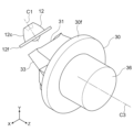
- FIG. 14 is a perspective view showing an example of the positional relationship between the light source 2 and the incident surfaces 38a and 38b.
- the headlamp device 100 has a plurality of light sources 2 arranged in the horizontal direction (ie, the X-axis direction). Although the number of light sources 2 is 17 here, it is not limited to this.
- Both of the incident surfaces 38a and 38b are, for example, cylindrical surfaces whose generatrix direction is the X-axis direction. In this case, both of the incident surfaces 38a and 38b have curvature in the YZ plane, but do not have curvature in the X-axis direction. However, the shape is not limited to this, and may have a curvature in the X-axis direction.
- a light distribution pattern 421a formed by the light ray R21 that entered the entrance surface 38a from each light source 2, and a light ray R22 that entered the entrance surface 38b from each light source 2.
- the formed light distribution pattern 421b forms a light distribution pattern 421 that is continuous in the vertical direction.
- ADB Adaptive Driving Beam
- the light sources 2 are turned on individually, it is possible to obtain a light distribution pattern 421 that is long in the vertical direction while suppressing spread in the horizontal direction on the irradiation surface 4.
- headlamp device 200 of Embodiment 2 is configured similarly to headlamp device 100 of Embodiment 1.
- the light emitted from the high beam light source 2 may be divided into three or more optical paths.
- the projection optical member 30 has the entrance surfaces 38a and 38b on which the light from the high beam light source 2 enters, and the projection optical member 30 has the entrance surfaces 38a and 38b on which the light from the high beam light source 2 enters. Split into optical paths. Further, the light passing through the incident surfaces 38a and 38b forms vertically continuous light distribution patterns 421a and 421b. Thereby, the light distribution pattern 42 can be formed in a wide range in the vertical direction on the irradiation surface 4, and the visibility of the high beam can be improved.
- the entrance surfaces 38a and 38b are formed in the projection optical member 3, they are not affected by assembly errors as would be the case if these were made as separate members. Therefore, the utilization efficiency of high beam light can be further improved.
- the incident surfaces 38a and 38b convert the light emitted from each light source 2 into a light ray R21 that travels on an optical path close to the focal position F of the exit surface 36, and a light ray R22 that travels on an optical path that is downward away from the focal position F. Since the light is divided, a vertically long light distribution pattern can be formed, and the luminous intensity of the area including the horizontal line can be increased. Furthermore, since the light rays R21 and R22 that have passed through the divided optical paths form a vertically continuous light distribution pattern, it is possible to form a vertically long light distribution pattern in the light source 2 in ADB.
- FIG. 15 is a cross-sectional view showing an example of the shape of the output surface of the projection optical member 30.
- the output surface 39 shown in FIG. 15 has a shape that overlaps the light distribution of the high beam.
- a surface area 39a above the optical axis C3 that is, on the +Y side
- the surface area 39b allows a large amount of the light ray R2 from the high beam light source 2 (FIG. 10) to pass through.
- the surface area 39b of the output surface 39 has the role of directing the light ray R2 passing through this surface area 39b downward. This allows the light forming the high beam light distribution pattern 42 (FIG. 13(A)) to be superimposed on the irradiation surface 4, making it easier to achieve the luminous intensity at the HV point required by the regulations for headlamp devices. Become.
- the surface area 39b of the output surface 39 also directs a part of the light ray R1 passing through this surface area 39b downward, but this part does not contribute to the sharpness of the cut-off line CL (FIG. 13(A)). .
- the legal compliance of the high beam can be improved without changing the shape of the cut-off line CL.
- a surface region 39c is formed at the upper end of the output surface 39 to direct a portion of the light from the low beam light source 1 above the cutoff line CL.
- the light passing through this surface area 39c can form an overhead sign light distribution above the cut-off line CL (FIG. 13(A)) of the irradiation surface 4 based on the regulations for headlamp devices.
- FIG. 16 is a diagram showing an example of a mounting structure for the low beam light source 1 and the high beam light source 2.
- the low beam light source 1 is attached to the end of the condensing optical element 12 in the -Z 1- axis direction.
- a flange 12f for fixing the condensing optical element 12 at the installation position is formed at the end of the condensing optical element 12 in the +Z 1- axis direction.
- the substrate 21 supporting the high beam light source 2 is attached to the projection optical member 30 so that the light source 2 faces the incident surfaces 38a and 38b.
- the light source 2 is arranged at a position close to the focal point F of the emission surface 36.
- FIG. 17 is a perspective view showing another example of the configuration of the projection optical member 30.
- the projection optical member 30 shown in FIG. 17 has a ring-shaped mounting rib 30f on its outer periphery for fixing the projection optical member 30 at the installation position. It is desirable that the mounting rib 30f be formed integrally with the same material as the projection optical member 30, such as resin.
- a fixing screw hole or the like can be formed in the mounting rib 30f. Since the mounting rib 30f is provided on the outer periphery of the projection optical member 30, it does not block the light rays R1 and R2, and therefore does not affect the light utilization efficiency and light distribution pattern.
- FIGS. 15 to 17 Although each configuration in FIGS. 15 to 17 has been described based on the projection optical member 30 of the second embodiment, it is also applicable to the projection optical member 3 of the first embodiment.
- first light source 1 Light source (first light source), 2 Light source (second light source), 3, 3A, 30 Projection optical member, 4 Irradiation surface, 12 Condensing optical member, 31 Incident surface (first incident surface), 32 Incident surface (second incident surface: condensing section), 33 reflecting surface (first reflecting surface), 34 reflecting surface (second reflecting surface), 35, 37 cut-off line forming section, 36, 39 output surface, 38 Incident plane (second incident plane: condensing part), 38a incident plane (first optical path splitting plane), 38b incident plane (second optical path dividing plane), 40, 41, 42, 42a, 42b, 421 arrangement Light pattern, 100, 200 headlight device, C1, C2, C3 optical axis, CL cutoff line forming part, F focal position.
Landscapes
- Engineering & Computer Science (AREA)
- General Engineering & Computer Science (AREA)
- Non-Portable Lighting Devices Or Systems Thereof (AREA)
Priority Applications (2)
| Application Number | Priority Date | Filing Date | Title |
|---|---|---|---|
| JP2024520198A JP7588762B2 (ja) | 2022-05-13 | 2022-05-13 | 前照灯装置 |
| PCT/JP2022/020161 WO2023218624A1 (ja) | 2022-05-13 | 2022-05-13 | 前照灯装置 |
Applications Claiming Priority (1)
| Application Number | Priority Date | Filing Date | Title |
|---|---|---|---|
| PCT/JP2022/020161 WO2023218624A1 (ja) | 2022-05-13 | 2022-05-13 | 前照灯装置 |
Publications (1)
| Publication Number | Publication Date |
|---|---|
| WO2023218624A1 true WO2023218624A1 (ja) | 2023-11-16 |
Family
ID=88730159
Family Applications (1)
| Application Number | Title | Priority Date | Filing Date |
|---|---|---|---|
| PCT/JP2022/020161 Ceased WO2023218624A1 (ja) | 2022-05-13 | 2022-05-13 | 前照灯装置 |
Country Status (2)
| Country | Link |
|---|---|
| JP (1) | JP7588762B2 (https=) |
| WO (1) | WO2023218624A1 (https=) |
Citations (4)
| Publication number | Priority date | Publication date | Assignee | Title |
|---|---|---|---|---|
| JP2015509647A (ja) * | 2012-03-07 | 2015-03-30 | ツィツァラ リヒトシステメ ゲーエムベーハー | 自動車用の照明装置 |
| WO2016006138A1 (ja) * | 2014-07-08 | 2016-01-14 | 三菱電機株式会社 | 前照灯モジュール及び前照灯装置 |
| WO2018003888A1 (ja) * | 2016-06-29 | 2018-01-04 | 株式会社小糸製作所 | 車両用灯具 |
| DE102019118051A1 (de) * | 2019-07-04 | 2021-01-07 | HELLA GmbH & Co. KGaA | Beleuchtungsvorrichtung für Fahrzeuge |
-
2022
- 2022-05-13 WO PCT/JP2022/020161 patent/WO2023218624A1/ja not_active Ceased
- 2022-05-13 JP JP2024520198A patent/JP7588762B2/ja active Active
Patent Citations (4)
| Publication number | Priority date | Publication date | Assignee | Title |
|---|---|---|---|---|
| JP2015509647A (ja) * | 2012-03-07 | 2015-03-30 | ツィツァラ リヒトシステメ ゲーエムベーハー | 自動車用の照明装置 |
| WO2016006138A1 (ja) * | 2014-07-08 | 2016-01-14 | 三菱電機株式会社 | 前照灯モジュール及び前照灯装置 |
| WO2018003888A1 (ja) * | 2016-06-29 | 2018-01-04 | 株式会社小糸製作所 | 車両用灯具 |
| DE102019118051A1 (de) * | 2019-07-04 | 2021-01-07 | HELLA GmbH & Co. KGaA | Beleuchtungsvorrichtung für Fahrzeuge |
Also Published As
| Publication number | Publication date |
|---|---|
| JP7588762B2 (ja) | 2024-11-22 |
| JPWO2023218624A1 (https=) | 2023-11-16 |
Similar Documents
| Publication | Publication Date | Title |
|---|---|---|
| JP6918191B2 (ja) | 前照灯モジュール及び車両用前照灯装置 | |
| JP6305660B2 (ja) | 前照灯モジュール及び前照灯装置 | |
| JP7292523B2 (ja) | 前照灯モジュール及び前照灯装置 | |
| JP6324635B2 (ja) | 前照灯モジュール及び前照灯装置 | |
| US10851957B2 (en) | Headlight module and headlight device | |
| CN107940388A (zh) | 前照灯模块和前照灯装置 | |
| JP7109681B2 (ja) | 前照灯モジュール及び前照灯装置 | |
| CN105814361A (zh) | 前照灯模块和前照灯装置 | |
| JP7031087B1 (ja) | 前照灯装置用光源分配素子、前照灯装置、及び前照灯モジュール | |
| JP7588762B2 (ja) | 前照灯装置 | |
| JP7134387B1 (ja) | 前照灯モジュール及び前照灯装置 |
Legal Events
| Date | Code | Title | Description |
|---|---|---|---|
| 121 | Ep: the epo has been informed by wipo that ep was designated in this application |
Ref document number: 22941703 Country of ref document: EP Kind code of ref document: A1 |
|
| ENP | Entry into the national phase |
Ref document number: 2024520198 Country of ref document: JP Kind code of ref document: A |
|
| NENP | Non-entry into the national phase |
Ref country code: DE |
|
| 122 | Ep: pct application non-entry in european phase |
Ref document number: 22941703 Country of ref document: EP Kind code of ref document: A1 |