WO2023218624A1 - Headlight device - Google Patents
Headlight device Download PDFInfo
- Publication number
- WO2023218624A1 WO2023218624A1 PCT/JP2022/020161 JP2022020161W WO2023218624A1 WO 2023218624 A1 WO2023218624 A1 WO 2023218624A1 JP 2022020161 W JP2022020161 W JP 2022020161W WO 2023218624 A1 WO2023218624 A1 WO 2023218624A1
- Authority
- WO
- WIPO (PCT)
- Prior art keywords
- light
- light source
- incident
- optical member
- projection optical
- Prior art date
Links
- 230000003287 optical effect Effects 0.000 claims abstract description 179
- 238000010586 diagram Methods 0.000 description 17
- 239000000463 material Substances 0.000 description 10
- 230000033228 biological regulation Effects 0.000 description 8
- 230000000694 effects Effects 0.000 description 8
- 239000004065 semiconductor Substances 0.000 description 7
- 230000005484 gravity Effects 0.000 description 6
- 238000004519 manufacturing process Methods 0.000 description 6
- 230000007423 decrease Effects 0.000 description 5
- 230000004907 flux Effects 0.000 description 3
- 239000011347 resin Substances 0.000 description 3
- 229920005989 resin Polymers 0.000 description 3
- CURLTUGMZLYLDI-UHFFFAOYSA-N Carbon dioxide Chemical compound O=C=O CURLTUGMZLYLDI-UHFFFAOYSA-N 0.000 description 2
- 239000011521 glass Substances 0.000 description 2
- 229910052736 halogen Inorganic materials 0.000 description 2
- 150000002367 halogens Chemical class 0.000 description 2
- 238000009434 installation Methods 0.000 description 2
- 238000005259 measurement Methods 0.000 description 2
- 229920001296 polysiloxane Polymers 0.000 description 2
- 239000007787 solid Substances 0.000 description 2
- 239000000758 substrate Substances 0.000 description 2
- 238000002834 transmittance Methods 0.000 description 2
- 238000007740 vapor deposition Methods 0.000 description 2
- 230000009471 action Effects 0.000 description 1
- 230000003044 adaptive effect Effects 0.000 description 1
- 230000004075 alteration Effects 0.000 description 1
- 229910002092 carbon dioxide Inorganic materials 0.000 description 1
- 239000001569 carbon dioxide Substances 0.000 description 1
- 230000008021 deposition Effects 0.000 description 1
- 238000005516 engineering process Methods 0.000 description 1
- 239000000446 fuel Substances 0.000 description 1
- 230000004313 glare Effects 0.000 description 1
- 238000005286 illumination Methods 0.000 description 1
- 230000007246 mechanism Effects 0.000 description 1
- 239000002184 metal Substances 0.000 description 1
- 230000004048 modification Effects 0.000 description 1
- 238000012986 modification Methods 0.000 description 1
- 230000000630 rising effect Effects 0.000 description 1
- 238000005019 vapor deposition process Methods 0.000 description 1
Images


Classifications
-
- F—MECHANICAL ENGINEERING; LIGHTING; HEATING; WEAPONS; BLASTING
- F21—LIGHTING
- F21S—NON-PORTABLE LIGHTING DEVICES; SYSTEMS THEREOF; VEHICLE LIGHTING DEVICES SPECIALLY ADAPTED FOR VEHICLE EXTERIORS
- F21S41/00—Illuminating devices specially adapted for vehicle exteriors, e.g. headlamps
- F21S41/20—Illuminating devices specially adapted for vehicle exteriors, e.g. headlamps characterised by refractors, transparent cover plates, light guides or filters
- F21S41/25—Projection lenses
- F21S41/27—Thick lenses
Definitions
- the present disclosure relates to a headlamp device having low beam and high beam functions.
- a headlamp device that includes a low beam light source and a high beam light source is known.
- the headlamp device disclosed in Patent Document 1 includes a projection lens, a low beam light source, a high beam light source, a reflector, and a shade.
- the reflector reflects the light emitted from the low beam light source toward the projection lens.
- the light reflected by the reflector is reflected by the top surface of the shade and enters the projection lens. At that time, part of the light is blocked by the shade to form a cut-off line. Furthermore, the light emitted from the high beam light source is reflected by the lower surface of the shade and enters the projection lens.
- the projection lens, reflector, and shade are each configured as separate members. Therefore, if the relative positional accuracy of each member decreases due to assembly errors, light that is not captured by the reflector or projection lens is generated, resulting in a decrease in light utilization efficiency. This problem becomes more prominent as headlamp devices become smaller.
- the present disclosure has been made to solve the above-mentioned problems, and aims to provide a headlamp device that can emit low beams and high beams, has high light utilization efficiency, and is suitable for downsizing.
- the headlamp device of the present disclosure includes a first light source for low beam, a second light source for high beam, and the light emitted from the first light source and the light emitted from the second light source enter, and a projection optical member that emits these lights from an output surface.
- the projection optical member has a first entrance surface into which light enters from a first light source, a second entrance surface into which light enters from a second light source, and an exit surface through which light enters from the first entrance surface. It has a first reflective surface that reflects light toward the output surface, and a second reflective surface that reflects light incident from the second incident surface toward the output surface.
- the second entrance surface has a light condensing section.
- a headlamp device that is capable of emitting low beam and high beam, has high light utilization efficiency, and is suitable for downsizing.
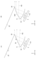
- FIG. 1 is a side view showing the configuration of a headlamp device according to Embodiment 1.
- FIG. FIG. 2 is a rear view showing the configuration of the headlamp device according to the first embodiment.
- (A) and (B) are side views showing a configuration example of a condensing optical element according to Embodiment 1.
- FIG. FIG. 3 is a side view showing a projection optical member of the headlamp device according to the first embodiment.
- (A) and (B) are diagrams showing a portion of the projection optical member of Embodiment 1 including a high beam light entrance surface.
- 1 is a diagram showing a light distribution pattern for a motorcycle formed by the headlamp device of Embodiment 1.
- FIG. 2 is a rear view showing an example of the headlamp device according to the first embodiment, which includes a cut-off line forming section that forms a light distribution pattern for a four-wheeled vehicle.
- 8 is a diagram showing a light distribution pattern for a four-wheeled vehicle formed by the headlamp device of FIG. 7.
- FIG. It is a side view which shows the projection optical member of a modification.
- FIG. 3 is a side view showing the configuration of a headlamp device according to a second embodiment.
- FIG. 7 is a diagram showing a portion of a projection optical member according to Embodiment 2, including a high beam light entrance surface.
- FIG. 7 is a diagram showing optical paths for low beam and high beam in the projection optical member according to the second embodiment.
- FIG. 7 is a perspective view showing a high beam light source and an incident surface of a projection optical member according to a second embodiment.
- FIG. 3 is a diagram showing an example of the shape of the output surface of the projection optical member of Embodiments 1 and 2.
- FIG. 2 is a side view showing an example of a mounting structure for a light source according to Embodiments 1 and 2.
- FIG. 2 is a side view showing an example of a projection optical member according to Embodiments 1 and 2.
- Light distribution refers to the luminous intensity distribution of a light source in space. In other words, light distribution is the spatial distribution of light emitted from a light source. Moreover, “luminous intensity” indicates the degree of intensity of light emitted by a light emitter. Luminous intensity is the luminous flux passing within a small solid angle in a certain direction divided by that solid angle.
- Light distribution pattern refers to the shape of a luminous flux and the intensity distribution of light caused by the direction of light emitted from a light source.
- Light distribution pattern is also used to mean an illuminance distribution pattern on an irradiation surface.
- Illuminance is a physical quantity representing the brightness of light irradiated onto a planar object, and is equal to the luminous flux irradiated per unit area.
- the light distribution pattern specified for automobile low beams in the Road Traffic Regulations has a horizontally long shape that is narrow in the vertical direction.
- the cutoff line which is the upper boundary line of the light distribution pattern, is required to be clear. In other words, it is required that the area above the cut-off line (ie, outside the light distribution pattern) is dark and the area below the cut-off line (ie, inside the light distribution pattern) is bright, that is, the cut-off line is clear.
- the "cutoff line” refers to the dividing line between bright and dark light that is created when the light emitted from the headlight device is irradiated onto a wall or screen, and is the dividing line at the top of the light distribution pattern. be.
- the "cutoff line” is the boundary line between bright and dark light above the light distribution pattern.
- the cut-off line is a boundary line between an upper bright area within the light distribution pattern and a dark area outside the light distribution pattern.
- the cut-off line is a term used to describe the function of adjusting the direction of light emitted from the headlight device when vehicles pass each other.
- the area below the cut-off line that is, the area inside the light distribution pattern and slightly below the cut-off line, is required to be the area of maximum illuminance.
- This area of maximum illuminance is called a "high illuminance area.”
- the "region below the cut-off line” means the upper region in the light distribution pattern, and corresponds to the part of the headlamp device that illuminates a distant area. In order to realize such a clear cut-off line, it is desirable that the cut-off line does not have large chromatic aberrations or blurring. "The cut-off line becomes blurred" means that the cut-off line becomes unclear.
- the shape of the cut-off line is determined by the laws and regulations of each country. Generally, in a low beam of a headlamp device for an automobile, the cutoff line has a stepped shape with a rising line.
- headlight device since the headlight device is placed on the front of the vehicle, design is important. In particular, many conventional headlight devices have circular openings, but there is a demand for headlight devices with even greater freedom in design. For example, a headlamp device having an elongated opening (i.e., an exit surface for emitting light) in the vertical direction of the vehicle has rarely been seen to date, and is thought to be able to enhance the design.
- an elongated opening i.e., an exit surface for emitting light
- the headlight device of the present disclosure is applied to a low beam or high beam of a vehicle headlight device. Further, the headlight device of the present disclosure is also applied to a low beam or high beam of a headlight device for a motorcycle. Furthermore, the headlight device of the present disclosure is also applied to low beams or high beams of headlight devices of other vehicles such as three-wheeled or four-wheeled vehicles.
- the cutoff line extends in the left-right direction of the vehicle, and the area inside the light distribution pattern and slightly below the cutoff line is the brightest.
- the light distribution pattern of the low beam of the headlight for four-wheeled vehicles has multiple steps in the light distribution pattern, taking into consideration the glare given to oncoming vehicles and vehicles in front. Commission for Europe).
- the high beam of the headlights extends in the left and right directions of the vehicle, and is the brightest in the central area of the horizon. This is the same for both motorcycles and automobiles.
- the high beam of the headlight uses multiple light sources or multiple headlight modules to selectively and dynamically illuminate multiple locations.
- the headlamp device according to the present disclosure can also be applied to a headlamp device for such uses.
- a three-wheeled vehicle is an automatic tricycle called a gyro.
- a ⁇ gyro tricycle'' is a three-wheeled scooter with one front wheel and one rear wheel with two wheels.
- tricycles are classified as motorized bicycles.
- a tricycle has a rotation axis near the center of the vehicle body, and most of the vehicle body, including the front wheels and driver's seat, can be tilted left and right. This mechanism allows a tricycle, like a motorcycle, to move its center of gravity inward when turning.
- the left and right direction of the vehicle is defined as the X-axis direction.
- the right side when facing the front of the vehicle is the +X-axis direction, and the left side when facing the front of the vehicle is the -X-axis direction.
- “Front” refers to the direction in which the vehicle moves forward. In other words, "forward” is the direction in which the headlights emit light.
- the vertical direction of the vehicle is defined as the Y-axis direction.
- the upper side is the +Y-axis direction
- the lower side is the -Y-axis direction.
- the traveling direction of the vehicle is assumed to be the Z-axis direction.
- the direction in which the vehicle moves forward is defined as the +Z-axis direction, and the opposite direction is defined as the -Z-axis direction.
- the +Z-axis direction is called the "front” direction, and the -Z-axis direction is called the "backward” direction.
- the +Z-axis direction is a direction in which a headlamp device mounted on a vehicle irradiates light.
- the ZX plane is a plane parallel to the road surface. Normally, a road surface can be considered a “horizontal surface.” For this reason, the ZX plane is also called a “horizontal plane.”
- a “horizontal plane” is a plane perpendicular to the direction of gravity.
- the road surface may be inclined with respect to the direction in which the vehicle is traveling. That is, when going uphill or downhill, the road surface is inclined with respect to the horizontal plane. In these cases, the "horizontal plane” is considered to be a plane parallel to the road surface. In other words, in this case, the "horizontal plane” is not considered to be a plane perpendicular to the direction of gravity.
- the "horizontal plane” is considered to be a plane perpendicular to the direction of gravity.
- the vehicle is perpendicular to the left-right direction of the road surface, this is considered to be equivalent to a state in which the vehicle is tilted in the left-right direction with respect to a "horizontal plane.”
- a "horizontal plane” is assumed to be a plane perpendicular to the direction of gravity. That is, the ZX plane will be explained assuming that the plane perpendicular to the direction of gravity is a plane.
- FIG. 1 is a side view showing a configuration example of a headlamp device 100 according to the first embodiment.
- FIG. 2 is a diagram of the headlamp device 100 of the first embodiment viewed from the ⁇ Z-axis side, that is, a rear view.
- the headlamp device 100 is a device for a vehicle.
- a headlamp device 100 according to the first embodiment includes a low beam light source 1 as a first light source, a high beam light source 2 as a second light source, and a projection optical member 3.
- the light source 1 may be a lamp light source such as an incandescent lamp, a halogen lamp, or a fluorescent lamp, or may be a semiconductor light source such as a light emitting diode (LED) or a laser diode (LD). Good too.
- a semiconductor light source is desirable from the viewpoint of reducing the burden on the environment by suppressing carbon dioxide (CO 2 ) emissions and fuel consumption.
- Semiconductor light sources are also desirable from the viewpoint of higher luminous efficiency than lamp light sources. Further, semiconductor light sources are desirable from the viewpoint of having higher directivity than lamp light sources and allowing the optical system to be made smaller and lighter.
- the light source 1 is located above the optical axis C3 of the projection optical member 3 (that is, in the +Y-axis direction).
- the light source 1 emits low beam light as first light.
- the light source 1 emits low beam light toward the projection optical member 3.
- the optical axis C1 of the light source 1 is inclined at an angle ⁇ with respect to the Y-axis direction.
- the headlamp device 100 has one light source 1.
- the headlamp device 100 may have a plurality of light sources 1 lined up in the X-axis direction.
- the light source 2 may be a lamp light source such as an incandescent lamp, a halogen lamp, or a fluorescent lamp, or may be a semiconductor light source such as an LED or LD.
- a semiconductor light source is desirable from the viewpoint of reducing the load on the environment. Semiconductor light sources are desirable because they have higher luminous efficiency than lamp light sources, and they are also desirable because they have higher directivity than lamp light sources and can make the optical system smaller and lighter.
- the light source 2 is located below the light source 1 (ie, in the ⁇ Y-axis direction). Further, the light source 2 is located below the optical axis C3 of the projection optical member 3. The light source 2 emits high beam light as second light. The light source 2 emits high beam light toward the projection optical member 3.
- the optical axis C2 of the light source 2 is inclined at an angle ⁇ with respect to the Y-axis direction.
- a plurality of light sources 2 are arranged in the X-axis direction. Each light source 2 can be turned on individually. The number of light sources 2 is 17 here. However, the number of light sources 2 may be greater or less than 17. Further, these light sources 2 are mounted on a substrate 21. The plurality of light sources 2 arranged in the X-axis direction are collectively referred to as a light source section 20.
- the headlamp device 100 may include a condensing optical element 12 as a condensing optical system.
- the condensing optical element 12 is an optical element having a condensing function, and condenses the light emitted from the light source 1 onto a reflecting surface 33 of the projection optical member 3, which will be described later. Thereby, the light emitted isotropically from the light source 1 can be efficiently used, and the light usage efficiency of the headlamp device 100 is improved.
- the condensing optical element 12 is made of, for example, transparent resin, light-transmitting glass, or silicone material.
- the material of the condensing optical element 12 is preferably a material with high light transmittance. Furthermore, since the condensing optical element 12 is placed immediately after the light source 1, a material with excellent heat resistance is preferable.
- FIG. 3(A) is a diagram showing an example of the configuration of the condensing optical element 12.
- the condensing optical element 12 shown in FIG. 3(A) has an incident surface 12a, an incident surface 12b, a reflective surface 12c, an output surface 12d, and an output surface 12e.
- the condensing optical element 12 is arranged on the output side of the light source 1, that is, on the side from which light is emitted from the light source 1.
- the optical axis of the condensing optical element 12 is common to the optical axis C1 of the light source 1.
- the condensing optical element 12 an X 1 Y 1 Z 1 orthogonal coordinate system, which is different from the XYZ orthogonal coordinate system, will be used for easy understanding.
- the X 1 Y 1 Z 1 orthogonal coordinate system is a coordinate system in which the XYZ orthogonal coordinate system is viewed from the +X-axis side and rotated clockwise by an angle ⁇ (FIG. 1) about the X-axis as the rotation center.
- the optical axis C1 of the condensing optical element 12 is parallel to the Z1 axis.
- the entrance surfaces 12a and 12b are arranged at positions where the light from the light source 1 enters.
- the entrance surface 12a has the shape of a rotating body centered on the optical axis C1.
- the entrance surface 12a has, for example, a circular cross-sectional shape perpendicular to the optical axis C1, and a cylindrical shape in which the diameter of the circle decreases in the +Z 1- axis direction.
- the entrance surface 12a has positive power.
- the entrance surface 12b is connected to the inner periphery of the end of the entrance surface 12a in the +Z 1- axis direction, and is located on the optical axis C1.
- the entrance surface 12b is a curved surface that is convex in the -Z uniaxial direction and has positive power.
- light rays with a large emission angle are incident on the incident surface 12a, and light rays with a small emission angle are incident on the incident surface 12b.
- the reflective surface 12c is arranged closer to the outer circumference than the incident surfaces 12a and 12b.
- the reflective surface 12c extends further in the +Z 1- axis direction from the end of the entrance surface 12a in the -Z 1- axis direction than the end of the entrance surface 12a in the +Z 1- axis direction. That is, the reflective surface 12c is arranged at a position where the light refracted by the incident surface 12a enters.
- the reflective surface 12c has, for example, a circular cross-sectional shape perpendicular to the optical axis C1, and a cylindrical shape in which the diameter of the circle increases in the + Z direction.
- the reflective surface 12c has positive power.
- the output surface 12d is connected to the end of the reflection surface 12c in the +Z 1- axis direction.
- the output surface 12d is a plane perpendicular to the optical axis C1.
- the output surface 12d has, for example, an annular shape centered on the optical axis C1.
- the output surface 12e is arranged on the optical axis C1.
- the exit surface 12e is a curved surface that is convex in the +Z uniaxial direction and has positive power.
- the outer periphery of the output surface 12e has, for example, a circular shape, and is connected to the inner periphery of the output surface 12d.
- the light rays with a large emission angle are incident on the incident surface 12a, and the light rays with a small emission angle are incident on the incident surface 12b.
- the light ray R11 is refracted by the incident surface 12a, moves toward the reflective surface 12c, is reflected by the reflective surface 12c, and then exits from the output surface 12d.
- the light ray R12 undergoes a refraction action at the entrance surface 12b, heads toward the exit surface 12e, and is emitted from the exit surface 12e.
- the light emitted from the light source 1 can be focused within the projection optical member 3, which will be described below.
- the shapes of the incident surfaces 12a, 12b, the reflective surface 12c, and the exit surfaces 12d, 12e have been specifically described, but the shapes described here are just examples, and are not limited to these shapes.
- the surface shape of the output surface 12d may be a curved surface having positive power.
- the entrance surface 12a, the entrance surface 12b, the reflection surface 12c, and the exit surface 12e are curved surfaces with positive power, they may be flat surfaces or curved surfaces with negative power.
- the condensing optical element 120 shown in FIG. 3(B) may be used instead of the condensing optical element 12 shown in FIG. 3(A).
- the condensing optical element 120 shown in FIG. 3(B) is composed of an optical lens having positive power.
- the condensing optical element 120 has an entrance surface 121 and an exit surface 122.
- the entrance surface 121 is composed of a curved surface that is convex in the -Z 1- axis direction
- the exit surface 122 is composed of a curved surface that is convex in the +Z 1- axis direction.
- the center of the entrance surface 121 and the center of the exit surface 122 are located on the optical axis C1.
- the condensing optical element 120 By configuring the condensing optical element 120 with an optical lens having positive power, the light emitted from the light source 1 can be condensed and emitted.
- the light beam emitted from the condensing optical element 120 is referred to as a light beam R13.
- the condensing optical element 120 is here constructed of a single optical lens having positive power, it may be constructed of a plurality of optical members combined so that the sum of each optical member has positive power. .
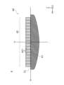
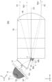
- FIG. 4 is a side view showing the light source 1, light source 2, condensing optical element 12, and projection optical member 3 of the first embodiment. As shown in FIG. 4, the light emitted from the light sources 1 and 2 enters the projection optical member 3. The projection optical member 3 emits the incident light forward (ie, in the +Z-axis direction). Further, the projection optical member 3 has a function of emitting the guided light as illumination light to be described later.
- the projection optical member 3 is made of, for example, transparent resin, light-transmissive glass, or silicone material. Further, the projection optical member 3 of the first embodiment has an interior filled with a light-transmitting refractive material, for example. In order to improve the light utilization efficiency, the material of the projection optical member 3 is preferably a material with high light transmittance. Further, since the projection optical member 3 is disposed immediately after the light source 2, a material with excellent heat resistance is preferably used.
- the projection optical member 3 includes an entrance surface 31 as a first entrance surface, an entrance surface 32 as a second entrance surface, a reflection surface 33 as a first reflection surface, and a reflection surface 33 as a second reflection surface. It has a surface 34, a cut-off line forming part 35, and an output surface 36.
- the entrance surface 31 as a first entrance surface is located in the +Z 1- axis direction of the condensing optical element 12 and faces the output surfaces 12d and 12e of the condensing optical element 12. That is, the entrance surface 31 is formed at a position where the light ray R1 emitted from the low beam light source 1 and passed through the condensing optical element 12 is incident.
- the light ray R1 is a combination of the light rays R11 and R12 shown in FIG. 3(A), or the light ray R13 shown in FIG. 3(B).
- the incident surface 31 is, for example, a plane perpendicular to the optical axis C1 of the light source 1.
- the entrance surface 31 may be formed of a curved surface.
- the entrance surface 31 is also located above the optical axis C3 of the projection optical member 3 (that is, in the +Y-axis direction).
- the entrance surface 32 as a second entrance surface is arranged to face the high beam light source 2.
- the entrance surface 32 is formed on the optical axis C2 of the light source 2. That is, the entrance surface 32 is formed at a position where the light ray R2 emitted from the light source 2 is incident.
- the entrance surface 32 is also located below the optical axis C3 of the projection optical member 3 (that is, in the ⁇ Y-axis direction). Further, a rear end portion of the incident surface 32 (that is, an end portion in the ⁇ Z-axis direction) and a rear end portion of a reflecting surface 34, which will be described later, are connected by a ridgeline E.
- the high beam of the headlamp device 100 is required to have high luminous intensity in order to brightly illuminate a distant area. Therefore, it is desirable to efficiently condense the light emitted from the light source 2 toward the reflective surface 34.
- FIG. 5(A) is a diagram showing the light source 2 and a portion of the projection optical member 3 including the entrance surface 32.
- the entrance surface 32 is composed of a curved surface having positive power. More specifically, the entrance surface 32 is formed of a curved surface that is convex toward the light source 2 side.
- the light ray R2 incident from the light source 2 is incident on the incident surface 32.
- the incident surface 32 condenses the incident light ray R2 toward the reflective surface 34.
- the entrance surface 32 has the function of condensing the light from the light source 2.
- the entrance surface 32 has a light condensing section. Due to the light condensing effect of the incident surface 32, more high beam light can be collected on the reflective surface 34, and a light distribution pattern with high luminous intensity can be formed.
- the entrance surface 32 is a curved surface that is convex toward the light source 2 side here, it is not limited to such a configuration and may have a positive power.
- the incident surface 32 is also referred to as a light condensing surface or a light condensing section.
- the reflective surface 33 as the first reflective surface is located below the incident surface 31 (ie, in the ⁇ Y-axis direction).
- the lower end of the reflective surface 33 ie, the end in the -Z-axis direction
- the reflective surface 33 reflects the light from the incident surface 31 forward (that is, in the +Z-axis direction) toward the exit surface 36 .
- the reflective surface 33 is a surface that generally faces the +Y-axis direction.
- the reflective surface 33 is a surface inclined at an angle ⁇ with respect to the ZX plane.
- the angle ⁇ may be 0 degrees, but is preferably larger than 0 degrees from the viewpoint of improving light utilization efficiency.
- the reflective surface 33 is shown as a plane in FIG. However, the reflective surface 33 is not limited to a flat surface, and may have a curved shape or a polyhedral shape in which a plurality of planes are connected.
- the reflective surface 34 as the second reflective surface is arranged below and adjacent to the reflective surface 33 (ie, in the ⁇ Y-axis direction).
- the reflective surface 34 is located at a position where the light incident from the incident surface 32 is incident.
- a cut-off line forming portion 35 is formed between the reflective surface 33 and the reflective surface 34.
- the reflective surface 34 is arranged above the incident surface 32 (that is, in the +Y-axis direction).
- a ridgeline E is formed between the reflective surface 34 and the incident surface 32.
- the configuration is not limited to this, and the reflective surface 34 and the incident surface 32 may be separated.
- the reflective surface 34 reflects the light from the incident surface 32 forward.
- the reflective surface 34 is a surface that generally faces the +Y-axis direction.
- the reflective surface 34 is a surface inclined at an angle ⁇ with respect to the ZX plane.
- the angle ⁇ may be 0 degrees, but from the viewpoint of improving light utilization efficiency, it is preferably larger than 0 degrees.
- Both of these reflective surfaces 33 and 34 may be mirror surfaces formed by mirror vapor deposition using metal or the like, but it is desirable that they function as total reflection surfaces without mirror vapor deposition. This is because the total reflection surface has a higher reflectance than the mirror surface and contributes to improving the light utilization efficiency. Further, by eliminating the mirror vapor deposition process, the manufacturing process of the projection optical member 3 can be simplified and manufacturing costs can be reduced. In the first embodiment, since the angle of incidence of the light rays on the reflective surfaces 33 and 34 is large, the reflective surfaces 33 and 34 can be made into total reflection surfaces without mirror deposition.
- the reflecting surface 34 that reflects the light incident from the incident surface 32 is shown as a flat surface in FIGS. 4 and 5(A), it may be a curved surface.
- a reflective surface 34A formed of a curved surface having positive power may be used.
- the cut-off line forming portion 35 is a ridgeline formed between the reflective surface 33 and the reflective surface 34.
- the cut-off line forming portion 35 is configured of a straight line extending in the X-axis direction. Further, the cut-off line forming portion 35 is located close to the focal point F of the output surface 36 in the Z-axis direction. Therefore, the illuminance distribution formed by each of the light sources 1 and 2 on the cut-off line forming section 35 is inverted and projected by the output surface 36, and becomes the light distribution pattern of the headlamp device 100.
- the output surface 36 is provided at the end of the projection optical member 3 in the +Z-axis direction.
- the exit surface 36 is a curved surface having positive power. More specifically, the output surface 36 is a curved surface that is convex in the +Z-axis direction.
- the output surface 36 outputs the light rays R1 and R2 reflected by the reflection surfaces 33 and 34 to the irradiation surface 4 in front (that is, in the +Z-axis direction).
- the optical axis C3 of the projection optical member 3 is a normal line passing through the surface apex of the output surface 36, and is parallel to the Z-axis here.
- the irradiation surface 4 (FIG. 1) is a virtual surface set at a prescribed position in front of the vehicle.
- the irradiation surface 4 is a surface parallel to the XY plane, that is, a vertical surface.
- the specified position in front of the vehicle is a position where the luminous intensity or illuminance of the headlamp device is measured, and is specified by road traffic regulations.
- the measurement position of the luminous intensity of an automobile headlamp device defined by the United Nations Economic Commission for Europe (UNECE) is a position 25 meters from the light source.
- the light intensity measurement position specified by Japan Industrial Standards Committee (JIS) in Japan is 10 m from the light source.
- the distance from the headlamp device 100 to the irradiation surface 4 is shown short for convenience of illustration, but the actual distance from the headlamp device 100 to the irradiation surface 4 is shorter than that shown in FIG. It's also long.
- the light beam emitted from below the optical axis C3 of the emission surface 36 is irradiated upward on the irradiation surface 4.
- the light beam emitted from above the optical axis C3 of the emission surface 36 is irradiated downward on the irradiation surface 4.
- the low beam light R1 emitted from the light source 1 enters the entrance surface 31 of the projection optical member 3, is reflected forward by the reflection surface 33, and is reflected forward by the exit surface 36.
- the irradiation surface 4 is irradiated from the irradiation surface 4.
- the high beam light R2 emitted from the light source 2 enters the entrance surface 32 of the projection optical member 3, is reflected forward by the reflection surface 34, and is irradiated onto the irradiation surface 4 from the exit surface 36.
- the projection optical member 3 integrally includes the incident surfaces 31 and 32, the reflective surfaces 33 and 34, and the output surface 36, so that the relative positions of each part are maintained with high precision. Ru. Therefore, the generation of stray light due to assembly errors can be suppressed, and light utilization efficiency can be improved.
- the utilization efficiency of the high beam light emitted from the light source 2 is improved, and the high beam A high luminous intensity can be obtained.
- the condensing optical element 12 by condensing the light emitted from the light source 1 toward the reflective surface 33 by the condensing optical element 12, the utilization efficiency of the low beam light emitted from the light source 1 is improved, and the low beam has high luminous intensity. can be obtained.
- the entrance surface 32 of the projection optical member 3 exhibits a light condensing effect, there is no need to arrange a condensing element as a separate member between the light source 2 and the projection optical member 3. Therefore, there is no need to increase the number of parts, and it is possible to downsize the headlamp device 100 and reduce manufacturing costs.
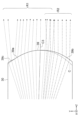
- FIG. 6 is a diagram showing a light distribution pattern 40 formed on the irradiation surface 4 by the headlamp device 100.
- the H line and the V line are straight lines passing through the HV point defined by the regulations regarding headlamp devices.
- the HV point is the intersection of the irradiation surface 4 and the optical axis C3 of the projection optical member 3.
- the H line is a straight line in the horizontal direction, and is also called a horizontal line.
- the V line is a straight line in the vertical direction, and is also called a vertical line.
- a light distribution pattern 41 for low beam is formed on the irradiation surface 4 by the light ray R1 emitted from the light source 1 for low beam, passed through the condensing optical element 12, the incident surface 31, and the reflective surface 33, and exited from the output surface 36. be done.
- a cut-off line CL is formed in the light distribution pattern 41 by the cut-off line forming section 35 .
- a light distribution pattern 42 for high beam is formed on the irradiation surface 4 by the light ray R2 emitted from the light source 2 for high beam, passed through the incident surface 32 and the reflective surface 33, and exited from the exit surface 36.
- the light distribution pattern 42 for high beam is located above the light distribution pattern 41 for low beam.
- the light distribution pattern 42 is a light distribution pattern 421 in which the image of the light source 2 is enlarged and projected and arranged in the X-axis direction.
- the cut-off line forming portion 35 is formed as a ridgeline between the reflective surface 33 and the reflective surface 34, but is not limited to this.
- the reflective surface 33 and the reflective surface 34 may be formed apart from each other.
- the above-mentioned headlamp device regulations require higher illuminance values around the cut-off line of the light distribution pattern. It is particularly desirable to form the cut-off line forming portion 35 as a ridge line between the reflective surface 33 and the reflective surface 34 because the illuminance value around the cut-off line of the light distribution pattern can be increased.
- a light distribution pattern having a straight cut-off line in the horizontal direction is mainly suitable for light distribution for motorcycles.
- a light distribution pattern having a stepped shape at the cut-off line is desirable from the viewpoint of legal compliance of the headlamp device.
- FIG. 7 is a view of the headlamp device 100 having the cut-off line forming section 37 that forms a light distribution pattern for a four-wheeled vehicle as viewed from the ⁇ Z-axis side, that is, a rear view.
- the cutoff line forming portion 37 has a stepped shape including a ridgeline portion 37a, a ridgeline portion 37b, and a ridgeline portion 37c.
- the ridgeline portions 37a, 37b, and 37c are located at the end in the +X-axis direction, the center in the X-axis direction, and the end in the -X-axis direction. Moreover, among the ridgeline parts 37a, 37b, and 37c, the height of the ridgeline part 37a (that is, the position in the Y-axis direction) is the lowest, and the height of the ridgeline part 37b is the highest. Further, the ridgeline portion 37a and the ridgeline portion 37b are connected via an inclined portion, and the ridgeline portion 37b and the ridgeline portion 37c are connected via an inclined portion.
- FIG. 8 is a diagram showing a light distribution pattern 40 formed on the irradiation surface 4 by the headlamp device 100 shown in FIG. 7.
- the stepped shape of the cut-off line forming portion 37 is inverted and projected. Therefore, the cut-off line CL of the light distribution pattern formed on the irradiation surface 4 has line portions CL1, CL2, and CL3 facing the ridge portions 37a, 37b, and 37c.
- Line portion CL1 is formed at a step lower than line portion CL3.
- Line portion CL1 is located on the opposite lane side, and line portion CL3 is located on the own lane side.
- the shape of the cutoff line CL shown in FIG. 8 is just an example. Depending on the uneven shape of the cut-off line forming portion 37, a light distribution pattern having a cut-off line CL having a desired uneven shape can be obtained.
- the headlamp device 100 of the first embodiment includes a light source 1 that emits low beam light, a light source 2 that emits high beam light, and projects light from the light sources 1 and 2. and a projection optical member 3.
- the projection optical member 3 includes an entrance surface 31 on which the light from the light source 1 enters, an entrance surface 32 on which the light from the light source 2 enters, a reflective surface 33 that reflects the light that entered from the entrance surface 31, and an entrance surface 32. It has a reflective surface 34 that reflects the light incident thereon, and an output surface 36 that emits the light reflected by the reflective surface 33 and the light reflected by the reflective surface 34.
- the projection optical member 3 has an entrance surface 31, an entrance surface 32, a reflection surface 33, a reflection surface 34, and an exit surface 36, the mutual positional accuracy of each part can be maintained, and the generation of stray light can be suppressed to achieve a high Light usage efficiency can be achieved. Further, even when the headlamp device 100 is downsized, the mutual positional accuracy of each part of the projection optical member 3 is maintained, and high light utilization efficiency can be obtained. That is, it is possible to realize a headlamp device 100 that can emit low beams and high beams, has high light utilization efficiency, and is suitable for downsizing.
- the entrance surface 32 of the projection optical member 3 has a light condensing section (that is, it has the function of condensing light), it is possible to improve the efficiency of high beam light use without increasing the number of parts, and to improve the high beam light utilization efficiency. High luminous intensity can be obtained.
- the headlamp device 100 includes the projection optical member 3 and the condensing optical element 12 separately.
- the projection optical member 3 and the condensing optical element 12 may be integrally configured.
- FIG. 9 shows a projection optical member 3A that is integrally equipped with a condensing section 301 that has the function of condensing the light emitted from the light source 1.
- the projection optical member 3A has a light condensing section 301 having incident surfaces 12a, 12b and a reflecting surface 12c.
- the projection optical member 30 also has an entrance surface 32 , reflection surfaces 33 and 34 , a cut-off line forming section 35 , and an exit surface 36 .
- the configurations of the incident surfaces 12a, 12b and reflective surface 12c of the condensing section 301 of the projection optical member 3A are similar to the incident surfaces 12a, 12b and the reflective surface 12c of the condensing optical element 12 described in the first embodiment.
- the light condensing section 301 condenses the light emitted from the light source 1 toward the reflective surface 33 of the projection optical member 3A.
- the configurations of the incident surface 32, reflective surfaces 33, 34, cut-off line forming section 35, and output surface 36 of the projection optical member 3A are as described in the first embodiment.
- the incident surface 12a of the condenser 301 Of the light emitted from the low beam light source 1, light rays with a large emission angle are incident on the incident surface 12a of the condenser 301, and light rays with a small emission angle are incident on the incident surface 12b.
- a light ray R11 that enters the incident surface 12a from the light source 1 is reflected by the reflective surface 12c and heads toward the reflective surface 33.
- the light ray R12 that has entered the incident surface 12a from the light source 1 passes through the incident surface 12b and heads toward the reflective surface 33.
- the light ray R1 which is a combination of the light rays R11 and R12, enters the reflective surface 33 and is reflected forward (that is, in the +Z-axis direction) by the reflective surface 33.
- the light ray R1 reflected by the reflective surface 33 is irradiated onto the irradiation surface 4 from the output surface 36.
- the light ray R2 emitted from the high beam light source 2 enters the entrance surface 32, is reflected by the reflection surface 34, and is irradiated from the exit surface 36 to the irradiation surface 4. .
- the incident surface 32 has a light condensing effect.
- the projection optical member 3A of the modified example integrally includes the condensing section 301, the degree of freedom in designing the condensing optical system is reduced, but the relative positional accuracy of each incident surface and each reflective surface is improved. In addition, since the number of parts is reduced, the headlamp device 100 can be further downsized.
- FIG. 10 is a diagram showing the configuration of a headlamp device 200 according to the second embodiment.
- a headlamp device 200 according to the second embodiment includes a low beam light source 1, a high beam light source 2, a condensing optical element 12, and a projection optical member 30.
- the headlamp device 200 of the second embodiment differs from the headlamp device 100 of the first embodiment in that the projection optical member 30 has entrance surfaces 38a and 38b into which light from the light source 2 enters.
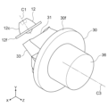
- FIG. 11 is a diagram showing the light source 2 and a portion of the projection optical member 30 including the entrance surfaces 38a and 38b.
- the projection optical member 30 is formed with an entrance surface 38a as a first optical path splitting surface so as to face the light source 2.
- An entrance surface 38b serving as a second optical path splitting surface is formed below and adjacent to the entrance surface 38a (in the ⁇ Y-axis direction).
- the entrance surface 38a is formed close to the focal point F (FIG. 12) of the exit surface 36, and the entrance surface 38b is formed away from the focal point F.
- the incident surface 38a has positive power and focuses the light incident from the light source 2 toward the reflective surface 34.
- the entrance surface 38a has, for example, a curved shape that is convex toward the light source 2 side.
- the entrance surface 38b has positive power and focuses the light incident from the light source 2 toward the exit surface 36.
- the entrance surface 38b has, for example, a curved shape that is convex toward the light source 2 side.
- a boundary portion D is formed between the entrance surface 38a and the entrance surface 38b.
- the boundary portion D is a ridgeline or a curved surface portion.
- the light that has traveled in the +Y-axis direction beyond the boundary D enters the entrance surface 38a, and the light that has traveled in the ⁇ Y-axis direction beyond the boundary D enters the entrance surface 38b. .
- the reflective surface 34 described in the first embodiment is formed in the +Y-axis direction of the incident surface 38a.
- the reflective surface 34 is formed at a position where the light incident from the incident surface 38a is incident.
- the incident surface 38a and the reflective surface 34 are connected by a ridgeline E.
- the reflective surface 34 reflects the light from the incident surface 38a forward (ie, in the +Z-axis direction) toward the exit surface 36.
- the reflective surface 34 is a flat surface in FIG. 11, it may have positive power like the reflective surface 34A shown in FIG. 5(B).
- the reflective surface 33 described in the first embodiment is formed in the +Y-axis direction of the reflective surface 34.
- a cut-off line forming portion 35 is formed between the reflective surface 33 and the reflective surface 34.
- the cut-off line forming portion 35 may be linear as shown in FIG. 2, or may have a stepped shape as shown in FIG.
- FIG. 12 is a diagram for explaining the optical path of light emitted from the high beam light source 2.
- the light ray R21 incident on the entrance surface 38a is reflected forward by the reflection surface 34A, passes through an optical path close to the focal point F, and is emitted from the exit surface 36.
- the light beam R21 emitted from the emission surface 36 is irradiated onto a region including the horizontal line on the irradiation surface 4.
- the light ray R22 that enters the entrance surface 38b passes through an optical path that is away from the focal position F downward (ie, in the ⁇ Y-axis direction), and is emitted from the exit surface 36.
- the light ray R22 emitted from the emission surface 36 is irradiated onto a region of the irradiation surface 4 that is away from the horizontal line upward (that is, in the +Y-axis direction).
- the light ray R1 emitted from the low beam light source 1 enters the projection optical member 30 from the entrance surface 31, is reflected forward by the reflection surface 33, and passes from the exit surface 36 to the irradiation surface. 4.
- FIG. 13(A) is a diagram showing a light distribution pattern formed by the headlamp device 200 according to the second embodiment. It is assumed that the cut-off line forming portion 35 has a stepped shape as shown in FIG. 7 .
- the light ray R21 that enters the incident surface 38a from the light source 2 is reflected by the reflective surface 34, passes through an optical path close to the focal point position F, and is emitted from the output surface 36, and forms a light distribution pattern above the cutoff line CL on the irradiation surface 4. 42a.
- the light ray R22 that has entered the entrance surface 38b from the light source 2 passes through an optical path away from the focal position F and is emitted from the exit surface 36, and on the irradiation surface 4, the light distribution pattern 42b above the light distribution pattern 42a is emitted.
- the light distribution pattern 42a and the light distribution pattern 42b are continuous in the vertical direction and form a long light distribution pattern in the vertical direction.
- the light distribution pattern 41 formed by the light emitted from the low beam light source 1 is as described in the first embodiment.
- the cutoff line CL has line portions CL1, CL2, and CL3 corresponding to the stepped shape of the cutoff line forming portion 35 (see FIG. 7).
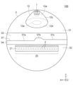
- FIG. 14 is a perspective view showing an example of the positional relationship between the light source 2 and the incident surfaces 38a and 38b.
- the headlamp device 100 has a plurality of light sources 2 arranged in the horizontal direction (ie, the X-axis direction). Although the number of light sources 2 is 17 here, it is not limited to this.
- Both of the incident surfaces 38a and 38b are, for example, cylindrical surfaces whose generatrix direction is the X-axis direction. In this case, both of the incident surfaces 38a and 38b have curvature in the YZ plane, but do not have curvature in the X-axis direction. However, the shape is not limited to this, and may have a curvature in the X-axis direction.
- a light distribution pattern 421a formed by the light ray R21 that entered the entrance surface 38a from each light source 2, and a light ray R22 that entered the entrance surface 38b from each light source 2.
- the formed light distribution pattern 421b forms a light distribution pattern 421 that is continuous in the vertical direction.
- ADB Adaptive Driving Beam
- the light sources 2 are turned on individually, it is possible to obtain a light distribution pattern 421 that is long in the vertical direction while suppressing spread in the horizontal direction on the irradiation surface 4.
- headlamp device 200 of Embodiment 2 is configured similarly to headlamp device 100 of Embodiment 1.
- the light emitted from the high beam light source 2 may be divided into three or more optical paths.
- the projection optical member 30 has the entrance surfaces 38a and 38b on which the light from the high beam light source 2 enters, and the projection optical member 30 has the entrance surfaces 38a and 38b on which the light from the high beam light source 2 enters. Split into optical paths. Further, the light passing through the incident surfaces 38a and 38b forms vertically continuous light distribution patterns 421a and 421b. Thereby, the light distribution pattern 42 can be formed in a wide range in the vertical direction on the irradiation surface 4, and the visibility of the high beam can be improved.
- the entrance surfaces 38a and 38b are formed in the projection optical member 3, they are not affected by assembly errors as would be the case if these were made as separate members. Therefore, the utilization efficiency of high beam light can be further improved.
- the incident surfaces 38a and 38b convert the light emitted from each light source 2 into a light ray R21 that travels on an optical path close to the focal position F of the exit surface 36, and a light ray R22 that travels on an optical path that is downward away from the focal position F. Since the light is divided, a vertically long light distribution pattern can be formed, and the luminous intensity of the area including the horizontal line can be increased. Furthermore, since the light rays R21 and R22 that have passed through the divided optical paths form a vertically continuous light distribution pattern, it is possible to form a vertically long light distribution pattern in the light source 2 in ADB.
- FIG. 15 is a cross-sectional view showing an example of the shape of the output surface of the projection optical member 30.
- the output surface 39 shown in FIG. 15 has a shape that overlaps the light distribution of the high beam.
- a surface area 39a above the optical axis C3 that is, on the +Y side
- the surface area 39b allows a large amount of the light ray R2 from the high beam light source 2 (FIG. 10) to pass through.
- the surface area 39b of the output surface 39 has the role of directing the light ray R2 passing through this surface area 39b downward. This allows the light forming the high beam light distribution pattern 42 (FIG. 13(A)) to be superimposed on the irradiation surface 4, making it easier to achieve the luminous intensity at the HV point required by the regulations for headlamp devices. Become.
- the surface area 39b of the output surface 39 also directs a part of the light ray R1 passing through this surface area 39b downward, but this part does not contribute to the sharpness of the cut-off line CL (FIG. 13(A)). .
- the legal compliance of the high beam can be improved without changing the shape of the cut-off line CL.
- a surface region 39c is formed at the upper end of the output surface 39 to direct a portion of the light from the low beam light source 1 above the cutoff line CL.
- the light passing through this surface area 39c can form an overhead sign light distribution above the cut-off line CL (FIG. 13(A)) of the irradiation surface 4 based on the regulations for headlamp devices.
- FIG. 16 is a diagram showing an example of a mounting structure for the low beam light source 1 and the high beam light source 2.
- the low beam light source 1 is attached to the end of the condensing optical element 12 in the -Z 1- axis direction.
- a flange 12f for fixing the condensing optical element 12 at the installation position is formed at the end of the condensing optical element 12 in the +Z 1- axis direction.
- the substrate 21 supporting the high beam light source 2 is attached to the projection optical member 30 so that the light source 2 faces the incident surfaces 38a and 38b.
- the light source 2 is arranged at a position close to the focal point F of the emission surface 36.
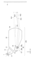
- FIG. 17 is a perspective view showing another example of the configuration of the projection optical member 30.
- the projection optical member 30 shown in FIG. 17 has a ring-shaped mounting rib 30f on its outer periphery for fixing the projection optical member 30 at the installation position. It is desirable that the mounting rib 30f be formed integrally with the same material as the projection optical member 30, such as resin.
- a fixing screw hole or the like can be formed in the mounting rib 30f. Since the mounting rib 30f is provided on the outer periphery of the projection optical member 30, it does not block the light rays R1 and R2, and therefore does not affect the light utilization efficiency and light distribution pattern.
- FIGS. 15 to 17 Although each configuration in FIGS. 15 to 17 has been described based on the projection optical member 30 of the second embodiment, it is also applicable to the projection optical member 3 of the first embodiment.
- first light source 1 Light source (first light source), 2 Light source (second light source), 3, 3A, 30 Projection optical member, 4 Irradiation surface, 12 Condensing optical member, 31 Incident surface (first incident surface), 32 Incident surface (second incident surface: condensing section), 33 reflecting surface (first reflecting surface), 34 reflecting surface (second reflecting surface), 35, 37 cut-off line forming section, 36, 39 output surface, 38 Incident plane (second incident plane: condensing part), 38a incident plane (first optical path splitting plane), 38b incident plane (second optical path dividing plane), 40, 41, 42, 42a, 42b, 421 arrangement Light pattern, 100, 200 headlight device, C1, C2, C3 optical axis, CL cutoff line forming part, F focal position.
Abstract
In the present invention, a headlight device (100) comprises: a first light source (1) for low beam; a second light source (2) for high beam; and a projection optical member (3) into which the light directed from the first light source (1) and the light directed from the second light source (2) enter, said projection optical member (3) having an emission surface (36) via which the light exits. The projection optical member (3) is provided with a first entry surface (31) through which the light from the first light source (1) enters, a second entry surface (32) through which light from the second light source (2) enters, a first reflection surface (33) that reflects light having entered through the first entry surface (31) toward the emission surface (36), and a second reflection surface (34) that reflects light having entered through the second entry surface (32) toward the emission surface (36). The second entry surface (32) is provided with a condenser.
Description
本開示は、ロービーム及びハイビーム機能を有する前照灯装置に関する。
The present disclosure relates to a headlamp device having low beam and high beam functions.
ロービーム用の光源とハイビーム用の光源とを備えた前照灯装置が知られている。例えば、特許文献1に開示された前照灯装置は、投影レンズと、ロービーム用の光源と、ハイビーム用の光源と、リフレクタと、シェードとを備えている。リフレクタは、ロービーム用の光源から出射された光を投影レンズに向けて反射する。
A headlamp device that includes a low beam light source and a high beam light source is known. For example, the headlamp device disclosed in Patent Document 1 includes a projection lens, a low beam light source, a high beam light source, a reflector, and a shade. The reflector reflects the light emitted from the low beam light source toward the projection lens.
リフレクタで反射された光は、シェードの上面で反射されて投影レンズに入射する。その際、光の一部がシェードによって遮断されてカットオフラインを形成する。また、ハイビーム用の光源から出射された光は、シェードの下面で反射されて投影レンズに入射する。
The light reflected by the reflector is reflected by the top surface of the shade and enters the projection lens. At that time, part of the light is blocked by the shade to form a cut-off line. Furthermore, the light emitted from the high beam light source is reflected by the lower surface of the shade and enters the projection lens.
しかしながら、特許文献1に開示された前照灯装置では、投影レンズ、リフレクタ及びシェードがそれぞれ別々の部材として構成されている。そのため、組立誤差により各部材の相互の位置精度が低下すると、リフレクタあるいは投影レンズに取り込まれない光が発生し、光利用効率が低下する。この課題は、前照灯装置の小型化が進むと、より顕著になる。
However, in the headlamp device disclosed in Patent Document 1, the projection lens, reflector, and shade are each configured as separate members. Therefore, if the relative positional accuracy of each member decreases due to assembly errors, light that is not captured by the reflector or projection lens is generated, resulting in a decrease in light utilization efficiency. This problem becomes more prominent as headlamp devices become smaller.
本開示は、上述した課題を解決するためになされたものであり、ロービーム及びハイビームを照射可能で、光利用効率が高く、小型化に適した前照灯装置を提供することを目的とする。
The present disclosure has been made to solve the above-mentioned problems, and aims to provide a headlamp device that can emit low beams and high beams, has high light utilization efficiency, and is suitable for downsizing.
本開示の前照灯装置は、ロービーム用の第1の光源と、ハイビーム用の第2の光源と、 第1の光源から出射された光及び第2の光源から出射された光が入射し、これらの光を出射面から出射する投射光学部材とを備える。投射光学部材は、第1の光源から光が入射する第1の入射面と、第2の光源から光が入射する第2の入射面と、第1の入射面から入射した光を出射面に向けて反射する第1の反射面と、第2の入射面から入射した光を出射面に向けて反射する第2の反射面とを有する。第2の入射面は、集光部を有する。
The headlamp device of the present disclosure includes a first light source for low beam, a second light source for high beam, and the light emitted from the first light source and the light emitted from the second light source enter, and a projection optical member that emits these lights from an output surface. The projection optical member has a first entrance surface into which light enters from a first light source, a second entrance surface into which light enters from a second light source, and an exit surface through which light enters from the first entrance surface. It has a first reflective surface that reflects light toward the output surface, and a second reflective surface that reflects light incident from the second incident surface toward the output surface. The second entrance surface has a light condensing section.
本開示によれば、ロービーム及びハイビームの照射が可能で、光利用効率が高く、小型化に適した前照灯装置を実現することができる。
According to the present disclosure, it is possible to realize a headlamp device that is capable of emitting low beam and high beam, has high light utilization efficiency, and is suitable for downsizing.
以下に、実施の形態に係る前照灯装置を、図面を参照しながら説明する。以下の実施の形態は例にすぎず、実施の形態を適宜組み合わせること及び各実施の形態を適宜変更することが可能である。
Hereinafter, a headlamp device according to an embodiment will be described with reference to the drawings. The following embodiments are merely examples, and the embodiments can be combined as appropriate and each embodiment can be modified as appropriate.
車両の前照灯装置は、道路交通規則などによって定められる配光パターンを満たさなければならない。「配光」とは、光源の空間に対する光度分布をいう。つまり、配光は、光源から出る光の空間的分布である。また、「光度」とは、発光体の放つ光の強さの程度を示すものである。光度は、ある方向の微小な立体角内を通る光束を、その立体角で割ったものである。
Vehicle headlight devices must satisfy the light distribution pattern specified by road traffic regulations. “Light distribution” refers to the luminous intensity distribution of a light source in space. In other words, light distribution is the spatial distribution of light emitted from a light source. Moreover, "luminous intensity" indicates the degree of intensity of light emitted by a light emitter. Luminous intensity is the luminous flux passing within a small solid angle in a certain direction divided by that solid angle.
「配光パターン」とは、光源から放射される光の方向に起因する光束の形状及び光の強度分布を示す。「配光パターン」は、照射面上での照度分布パターンの意味としても使用される。「照度」とは、平面状の物体に照射された光の明るさを表す物理量のことであり、単位面積当たりに照射された光束に等しい。
"Light distribution pattern" refers to the shape of a luminous flux and the intensity distribution of light caused by the direction of light emitted from a light source. "Light distribution pattern" is also used to mean an illuminance distribution pattern on an irradiation surface. "Illuminance" is a physical quantity representing the brightness of light irradiated onto a planar object, and is equal to the luminous flux irradiated per unit area.
道路交通規則において自動車用ロービームに関して規定された配光パターンは、上下方向が狭い横長の形状を有する。対向車を眩惑させないために、配光パターンの上側の境界線であるカットオフラインは明瞭であることが要求される。つまり、カットオフラインより上側(すなわち、配光パターンの外側)が暗く、カットオフラインより下側(すなわち、配光パターンの内側)が明るいこと、すなわち、カットオフラインが明瞭であることが要求される。
The light distribution pattern specified for automobile low beams in the Road Traffic Regulations has a horizontally long shape that is narrow in the vertical direction. In order not to dazzle oncoming vehicles, the cutoff line, which is the upper boundary line of the light distribution pattern, is required to be clear. In other words, it is required that the area above the cut-off line (ie, outside the light distribution pattern) is dark and the area below the cut-off line (ie, inside the light distribution pattern) is bright, that is, the cut-off line is clear.
ここで、「カットオフライン」とは、前照灯装置から出射された光を壁又はスクリーンに照射した場合にできる光の明暗の区切り線のことで、配光パターンの上側の区切り線のことである。つまり、「カットオフライン」とは、配光パターンの上側の光の明暗の境界線のことである。つまり、カットオフラインは、配光パターン内における上側の光の明るい領域と配光パターン外における光の暗い領域との間の境界線のことである。カットオフラインは、車両がすれ違う際に前照灯装置から出射される光の照射方向を調節する機能を説明するために用いられる用語である。
Here, the "cutoff line" refers to the dividing line between bright and dark light that is created when the light emitted from the headlight device is irradiated onto a wall or screen, and is the dividing line at the top of the light distribution pattern. be. In other words, the "cutoff line" is the boundary line between bright and dark light above the light distribution pattern. In other words, the cut-off line is a boundary line between an upper bright area within the light distribution pattern and a dark area outside the light distribution pattern. The cut-off line is a term used to describe the function of adjusting the direction of light emitted from the headlight device when vehicles pass each other.
そして、カットオフラインより下側の領域、すなわち、配光パターンの内側であってカットオフラインより少し下の領域が最大照度の領域となることが要求される。この最大照度の領域は、「高照度領域」と呼ばれる。ここで、「カットオフラインより下側の領域」とは、配光パターン内における上部の領域を意味し、前照灯装置では遠方を照射する部分に相当する。このような明瞭なカットオフラインを実現するためには、カットオフラインに大きな色収差及びぼやけなどが生じないことが望ましい。「カットオフラインにぼやけが生じる」とは、カットオフラインが不鮮明になることである。
The area below the cut-off line, that is, the area inside the light distribution pattern and slightly below the cut-off line, is required to be the area of maximum illuminance. This area of maximum illuminance is called a "high illuminance area." Here, the "region below the cut-off line" means the upper region in the light distribution pattern, and corresponds to the part of the headlamp device that illuminates a distant area. In order to realize such a clear cut-off line, it is desirable that the cut-off line does not have large chromatic aberrations or blurring. "The cut-off line becomes blurred" means that the cut-off line becomes unclear.
カットオフラインの形状は各国の法規によって定められている。一般に、自動車用の前照灯装置のロービームでは、カットオフラインは立ち上がりラインを有する段違い形状を有する。
The shape of the cut-off line is determined by the laws and regulations of each country. Generally, in a low beam of a headlamp device for an automobile, the cutoff line has a stepped shape with a rising line.
また、前照灯装置は自動車の前面に配置されるため意匠性が重要である。特に、従来の前照灯装置は円形の開口を有するものが多くみられたが、更に意匠の自由度を高めた前照灯装置が求められている。例えば、車両の垂直方向に縦長の開口(すなわち、光を出射する出射面)を有する前照灯装置は、これまでにほとんど見られず、意匠性を高めることができると考えられる。
Additionally, since the headlight device is placed on the front of the vehicle, design is important. In particular, many conventional headlight devices have circular openings, but there is a demand for headlight devices with even greater freedom in design. For example, a headlamp device having an elongated opening (i.e., an exit surface for emitting light) in the vertical direction of the vehicle has rarely been seen to date, and is thought to be able to enhance the design.
本開示の前照灯装置は、車両の前照灯装置のロービーム又はハイビームなどに適用される。また、本開示の前照灯装置は、自動二輪車用の前照灯装置のロービーム又はハイビームなどにも適用される。また、本開示の前照灯装置は、三輪又は四輪などのその他の車両の前照灯装置のロービーム又はハイビームなどにも適用される。
The headlight device of the present disclosure is applied to a low beam or high beam of a vehicle headlight device. Further, the headlight device of the present disclosure is also applied to a low beam or high beam of a headlight device for a motorcycle. Furthermore, the headlight device of the present disclosure is also applied to low beams or high beams of headlight devices of other vehicles such as three-wheeled or four-wheeled vehicles.
以下では、自動二輪車用及び四輪車用に適用される前照灯のロービーム及びハイビームの配光パターンを形成する場合を例として説明する。自動二輪車用の前照灯のロービームの配光パターンは、カットオフラインが車両の左右方向に伸びており、配光パターンの内側であってカットオフラインの少し下側の領域が最も明るい。また、四輪車用の前照灯のロービームの配光パターンは、対向車両や前方の車両に与える眩輝を考慮して、配光パターンに複数の段差を有するものが、欧州のECE(Economic
Commission for Europe)によって定義されている。 In the following, a case will be described as an example in which light distribution patterns for low beams and high beams of headlights applied to motorcycles and four-wheeled vehicles are formed. In the low beam light distribution pattern of a motorcycle headlamp, the cutoff line extends in the left-right direction of the vehicle, and the area inside the light distribution pattern and slightly below the cutoff line is the brightest. In addition, the light distribution pattern of the low beam of the headlight for four-wheeled vehicles has multiple steps in the light distribution pattern, taking into consideration the glare given to oncoming vehicles and vehicles in front.
Commission for Europe).
前照灯のハイビームは、車両の左右方向に伸びており、水平線の中央領域が最も明るい。これは自動二輪車用及び四輪車用ともに同様である。
The high beam of the headlights extends in the left and right directions of the vehicle, and is the brightest in the central area of the horizon. This is the same for both motorcycles and automobiles.
さらに、前照灯のハイビームには複数の光源、又は、複数の前照灯モジュールを用いて選択的に複数箇所を動的に照射する技術が提案されている。本開示に係る前照灯装置はそのような用途の前照灯装置にも適用することができる。
Further, a technology has been proposed in which the high beam of the headlight uses multiple light sources or multiple headlight modules to selectively and dynamically illuminate multiple locations. The headlamp device according to the present disclosure can also be applied to a headlamp device for such uses.
三輪の車両としては、例えば、ジャイロと呼ばれる自動三輪車が挙げられる。「ジャイロと呼ばれる自動三輪車」とは、前輪が一輪で、後輪が一軸二輪の三輪でできたスクーターである。日本では、自動三輪車は原動機付自転車に該当する。自動三輪車は、車体中央付近に回転軸を持ち、前輪及び運転席を含む車体のほとんどを左右方向に傾けることができる。この機構によって、自動三輪車は、自動二輪車と同様に旋回の際に内側へ重心を移動することができる。
An example of a three-wheeled vehicle is an automatic tricycle called a gyro. A ``gyro tricycle'' is a three-wheeled scooter with one front wheel and one rear wheel with two wheels. In Japan, tricycles are classified as motorized bicycles. A tricycle has a rotation axis near the center of the vehicle body, and most of the vehicle body, including the front wheels and driver's seat, can be tilted left and right. This mechanism allows a tricycle, like a motorcycle, to move its center of gravity inward when turning.
以下の実施の形態の説明では、説明を容易にするためにXYZ座標系の座標軸及び座標平面を用いる。車両の左右方向をX軸方向とする。車両の前方を向いたときの右側を+X軸方向とし、車両の前方を向いたときの左側を-X軸方向とする。「前方」とは、車両の前進時の進行方向をいう。つまり、「前方」とは、前照灯が光を照射する方向である。また、車両の上下方向をY軸方向とする。上側を+Y軸方向とし、下側を-Y軸方向とする。「上側」とは空の方向であり、「下側」とは地面(すなわち、路面)の方向である。また、車両の進行方向をZ軸方向とする。車両の前進時の進行方向を+Z軸方向とし、その反対の方向を-Z軸方向とする。+Z軸方向を「前方」と呼び、-Z軸方向を「後方」と呼ぶ。+Z軸方向は、車両に搭載された前照灯装置が光を照射する方向である。
In the following description of the embodiment, coordinate axes and coordinate planes of an XYZ coordinate system will be used for ease of explanation. The left and right direction of the vehicle is defined as the X-axis direction. The right side when facing the front of the vehicle is the +X-axis direction, and the left side when facing the front of the vehicle is the -X-axis direction. "Front" refers to the direction in which the vehicle moves forward. In other words, "forward" is the direction in which the headlights emit light. Further, the vertical direction of the vehicle is defined as the Y-axis direction. The upper side is the +Y-axis direction, and the lower side is the -Y-axis direction. "Upper side" is toward the sky, and "lower side" is toward the ground (ie, road surface). Further, the traveling direction of the vehicle is assumed to be the Z-axis direction. The direction in which the vehicle moves forward is defined as the +Z-axis direction, and the opposite direction is defined as the -Z-axis direction. The +Z-axis direction is called the "front" direction, and the -Z-axis direction is called the "backward" direction. The +Z-axis direction is a direction in which a headlamp device mounted on a vehicle irradiates light.
また、ZX平面は、路面に平行な面である。通常、路面は「水平面」とみなせる。このため、ZX平面は、「水平面」とも呼ぶ。「水平面」とは、重力の方向に直交する平面である。しかし、路面は、車両の走行方向に対して傾くことがある。つまり、登り坂又は下り坂などでは、路面は水平面に対して傾く。これらの場合には、「水平面」は、路面に平行な面とみなす。つまり、この場合には、「水平面」は、重力の方向に対して垂直な平面ではないものとみなす。
Additionally, the ZX plane is a plane parallel to the road surface. Normally, a road surface can be considered a "horizontal surface." For this reason, the ZX plane is also called a "horizontal plane." A "horizontal plane" is a plane perpendicular to the direction of gravity. However, the road surface may be inclined with respect to the direction in which the vehicle is traveling. That is, when going uphill or downhill, the road surface is inclined with respect to the horizontal plane. In these cases, the "horizontal plane" is considered to be a plane parallel to the road surface. In other words, in this case, the "horizontal plane" is not considered to be a plane perpendicular to the direction of gravity.
一方、一般的な路面が車両の走行方向に対して左右方向に傾いていることは稀である。「左右方向」とは、走路の幅方向である。これらの場合には、「水平面」は、重力方向に対して直交する面として考える。例えば、路面が左右方向に傾き、車両が路面の左右方向に対して垂直であったとしても、車両が「水平面」に対して左右方向に傾いた状態と同等として考える。以下では、理解を容易にするために、「水平面」は、重力方向に垂直は平面とみなして説明を行う。つまり、ZX平面は、重力方向に垂直は平面とみなして説明を行う。
On the other hand, it is rare for a typical road surface to be inclined laterally with respect to the direction in which the vehicle is traveling. The "left-right direction" is the width direction of the running track. In these cases, the "horizontal plane" is considered to be a plane perpendicular to the direction of gravity. For example, even if the road surface is tilted in the left-right direction and the vehicle is perpendicular to the left-right direction of the road surface, this is considered to be equivalent to a state in which the vehicle is tilted in the left-right direction with respect to a "horizontal plane." In the following explanation, in order to facilitate understanding, a "horizontal plane" is assumed to be a plane perpendicular to the direction of gravity. That is, the ZX plane will be explained assuming that the plane perpendicular to the direction of gravity is a plane.
《実施の形態1》
〈前照灯装置100〉
図1は、実施の形態1の前照灯装置100の構成例を示す側面図である。図2は、実施の形態1の前照灯装置100を-Z軸側から見た図、すなわち背面図である。前照灯装置100は、車両用の装置である。実施の形態1に係る前照灯装置100は、第1の光源としてのロービーム用の光源1と、第2の光源としてのハイビーム用の光源2と、投射光学部材3とを備える。 《Embodiment 1》
<Headlight device 100>
FIG. 1 is a side view showing a configuration example of aheadlamp device 100 according to the first embodiment. FIG. 2 is a diagram of the headlamp device 100 of the first embodiment viewed from the −Z-axis side, that is, a rear view. The headlamp device 100 is a device for a vehicle. A headlamp device 100 according to the first embodiment includes a low beam light source 1 as a first light source, a high beam light source 2 as a second light source, and a projection optical member 3.
〈前照灯装置100〉
図1は、実施の形態1の前照灯装置100の構成例を示す側面図である。図2は、実施の形態1の前照灯装置100を-Z軸側から見た図、すなわち背面図である。前照灯装置100は、車両用の装置である。実施の形態1に係る前照灯装置100は、第1の光源としてのロービーム用の光源1と、第2の光源としてのハイビーム用の光源2と、投射光学部材3とを備える。 《
<
FIG. 1 is a side view showing a configuration example of a
〈光源1〉
光源1は、白熱電球、ハロゲンランプ、又は蛍光ランプなどのランプ光源であってもよく、発光ダイオード(Light Emitting Diode(LED))又はレーザーダイオード(Laser Diode(LD))などの半導体光源であってもよい。二酸化炭素(CO2)の排出と燃料の消費を抑えるといった環境への負荷を軽減する観点から、半導体光源が望ましい。半導体光源は、ランプ光源に比べて発光効率が高い観点でも望ましい。また、半導体光源は、ランプ光源に比べて指向性が高く、光学系を小型化及び軽量化できる観点でも望ましい。 <Light source 1>
Thelight source 1 may be a lamp light source such as an incandescent lamp, a halogen lamp, or a fluorescent lamp, or may be a semiconductor light source such as a light emitting diode (LED) or a laser diode (LD). Good too. A semiconductor light source is desirable from the viewpoint of reducing the burden on the environment by suppressing carbon dioxide (CO 2 ) emissions and fuel consumption. Semiconductor light sources are also desirable from the viewpoint of higher luminous efficiency than lamp light sources. Further, semiconductor light sources are desirable from the viewpoint of having higher directivity than lamp light sources and allowing the optical system to be made smaller and lighter.
光源1は、白熱電球、ハロゲンランプ、又は蛍光ランプなどのランプ光源であってもよく、発光ダイオード(Light Emitting Diode(LED))又はレーザーダイオード(Laser Diode(LD))などの半導体光源であってもよい。二酸化炭素(CO2)の排出と燃料の消費を抑えるといった環境への負荷を軽減する観点から、半導体光源が望ましい。半導体光源は、ランプ光源に比べて発光効率が高い観点でも望ましい。また、半導体光源は、ランプ光源に比べて指向性が高く、光学系を小型化及び軽量化できる観点でも望ましい。 <
The
光源1は、投射光学部材3の光軸C3に対して上方(すなわち+Y軸方向)に位置している。光源1は、第1の光としてのロービーム用の光を発する。光源1は、投射光学部材3に向けてロービーム用の光を発する。光源1の光軸C1は、Y軸方向に対して角度αだけ傾斜している。
The light source 1 is located above the optical axis C3 of the projection optical member 3 (that is, in the +Y-axis direction). The light source 1 emits low beam light as first light. The light source 1 emits low beam light toward the projection optical member 3. The optical axis C1 of the light source 1 is inclined at an angle α with respect to the Y-axis direction.
図1及び図2に示した例では、前照灯装置100は、1つの光源1を有している。しかしながら、前照灯装置100は、X軸方向に並ぶ複数の光源1を有していてもよい。
In the example shown in FIGS. 1 and 2, the headlamp device 100 has one light source 1. However, the headlamp device 100 may have a plurality of light sources 1 lined up in the X-axis direction.
〈光源2〉
光源2は、白熱電球、ハロゲンランプ、又は蛍光ランプなどのランプ光源であってもよく、LED又はLDなどの半導体光源であってもよい。光源1と同様、環境への負荷を軽減する観点から、半導体光源が望ましい。半導体光源は、ランプ光源に比べて発光効率が高い観点でも望ましく、また、ランプ光源に比べて指向性が高く、光学系を小型化及び軽量化できる観点でも望ましい。 <Light source 2>
Thelight source 2 may be a lamp light source such as an incandescent lamp, a halogen lamp, or a fluorescent lamp, or may be a semiconductor light source such as an LED or LD. Like the light source 1, a semiconductor light source is desirable from the viewpoint of reducing the load on the environment. Semiconductor light sources are desirable because they have higher luminous efficiency than lamp light sources, and they are also desirable because they have higher directivity than lamp light sources and can make the optical system smaller and lighter.
光源2は、白熱電球、ハロゲンランプ、又は蛍光ランプなどのランプ光源であってもよく、LED又はLDなどの半導体光源であってもよい。光源1と同様、環境への負荷を軽減する観点から、半導体光源が望ましい。半導体光源は、ランプ光源に比べて発光効率が高い観点でも望ましく、また、ランプ光源に比べて指向性が高く、光学系を小型化及び軽量化できる観点でも望ましい。 <
The
光源2は、光源1に対して下方(すなわち-Y軸方向)に位置している。また、光源2は、投射光学部材3の光軸C3に対して下方に位置している。光源2は、第2の光としてのハイビーム用の光を発する。光源2は、ハイビーム用の光を投射光学部材3に向けて出射する。光源2の光軸C2は、Y軸方向に対して角度βだけ傾斜している。
The light source 2 is located below the light source 1 (ie, in the −Y-axis direction). Further, the light source 2 is located below the optical axis C3 of the projection optical member 3. The light source 2 emits high beam light as second light. The light source 2 emits high beam light toward the projection optical member 3. The optical axis C2 of the light source 2 is inclined at an angle β with respect to the Y-axis direction.
図2に示すように、複数の光源2がX軸方向に配列されている。それぞれの光源2は、個別に点灯可能である。光源2の数は、ここでは17個である。但し、光源2の数は17個より多くても少なくても良い。また、これらの光源2は、基板21に実装されている。X軸方向に配列された複数の光源2をまとめて、光源部20と称する。
As shown in FIG. 2, a plurality of light sources 2 are arranged in the X-axis direction. Each light source 2 can be turned on individually. The number of light sources 2 is 17 here. However, the number of light sources 2 may be greater or less than 17. Further, these light sources 2 are mounted on a substrate 21. The plurality of light sources 2 arranged in the X-axis direction are collectively referred to as a light source section 20.
〈集光光学素子12〉
前照灯装置100は、集光光学系としての集光光学素子12を備えていてもよい。集光光学素子12は、集光機能を有する光学素子であり、光源1から出射された光を投射光学部材3の後述する反射面33に集光する。これにより、光源1から等方的に放射される光を効率良く利用することができ、前照灯装置100の光利用効率が向上する。 <Condensingoptical element 12>
Theheadlamp device 100 may include a condensing optical element 12 as a condensing optical system. The condensing optical element 12 is an optical element having a condensing function, and condenses the light emitted from the light source 1 onto a reflecting surface 33 of the projection optical member 3, which will be described later. Thereby, the light emitted isotropically from the light source 1 can be efficiently used, and the light usage efficiency of the headlamp device 100 is improved.
前照灯装置100は、集光光学系としての集光光学素子12を備えていてもよい。集光光学素子12は、集光機能を有する光学素子であり、光源1から出射された光を投射光学部材3の後述する反射面33に集光する。これにより、光源1から等方的に放射される光を効率良く利用することができ、前照灯装置100の光利用効率が向上する。 <Condensing
The
集光光学素子12は、例えば、透明樹脂、光透過性を有する硝子又はシリコーン(silicone)材で製作されていることが好ましい。光利用効率を高めるために、集光光学素子12の材料は、光透過性の高い材料であることが好ましい。また、集光光学素子12が光源1の直後に配置されることから、耐熱性に優れた材料が好ましい。
It is preferable that the condensing optical element 12 is made of, for example, transparent resin, light-transmitting glass, or silicone material. In order to increase light utilization efficiency, the material of the condensing optical element 12 is preferably a material with high light transmittance. Furthermore, since the condensing optical element 12 is placed immediately after the light source 1, a material with excellent heat resistance is preferable.
図3(A)は、集光光学素子12の一構成例を示す図である。図3(A)に示した集光光学素子12は、入射面12a、入射面12b、反射面12c、出射面12d及び出射面12eを有する。集光光学素子12は、光源1の出射側、すなわち光源1から光が発せられる側に配置されている。集光光学素子12の光軸は、光源1の光軸C1と共通である。
FIG. 3(A) is a diagram showing an example of the configuration of the condensing optical element 12. The condensing optical element 12 shown in FIG. 3(A) has an incident surface 12a, an incident surface 12b, a reflective surface 12c, an output surface 12d, and an output surface 12e. The condensing optical element 12 is arranged on the output side of the light source 1, that is, on the side from which light is emitted from the light source 1. The optical axis of the condensing optical element 12 is common to the optical axis C1 of the light source 1.
集光光学素子12の説明では、理解を容易にするために、XYZ直交座標系とは異なるX1Y1Z1直交座標系を用いる。X1Y1Z1直交座標系は、XYZ直交座標系を+X軸側から見て、X軸を回転中心として時計回りに角度α(図1)だけ回転させた座標系である。集光光学素子12の光軸C1は、Z1軸に平行である。
In the description of the condensing optical element 12, an X 1 Y 1 Z 1 orthogonal coordinate system, which is different from the XYZ orthogonal coordinate system, will be used for easy understanding. The X 1 Y 1 Z 1 orthogonal coordinate system is a coordinate system in which the XYZ orthogonal coordinate system is viewed from the +X-axis side and rotated clockwise by an angle α (FIG. 1) about the X-axis as the rotation center. The optical axis C1 of the condensing optical element 12 is parallel to the Z1 axis.
入射面12a,12bは、光源1からの光が入射する位置に配置されている。入射面12aは、光軸C1を中心とする回転体形状を有する。入射面12aは、例えば、光軸C1に直交する断面形状が円形であり、その円の直径が+Z1軸方向に小さくなる筒状である。入射面12aは、正のパワーを有する。
The entrance surfaces 12a and 12b are arranged at positions where the light from the light source 1 enters. The entrance surface 12a has the shape of a rotating body centered on the optical axis C1. The entrance surface 12a has, for example, a circular cross-sectional shape perpendicular to the optical axis C1, and a cylindrical shape in which the diameter of the circle decreases in the +Z 1- axis direction. The entrance surface 12a has positive power.
入射面12bは、入射面12aの+Z1軸方向の端部の内周に接続され、光軸C1上に位置する。入射面12bは、-Z1軸方向に凸となる曲面であり、正のパワーを有する。光源1から出射された光のうち、出射角度の大きい光線は入射面12aに入射し、出射角度の小さい光線は入射面12bに入射する。
The entrance surface 12b is connected to the inner periphery of the end of the entrance surface 12a in the +Z 1- axis direction, and is located on the optical axis C1. The entrance surface 12b is a curved surface that is convex in the -Z uniaxial direction and has positive power. Of the light emitted from the light source 1, light rays with a large emission angle are incident on the incident surface 12a, and light rays with a small emission angle are incident on the incident surface 12b.
反射面12cは、入射面12a,12bよりも外周側に配置されている。反射面12cは、入射面12aの-Z1軸方向の端部から、入射面12aの+Z1軸方向の端部よりもさらに+Z1軸方向に延在している。すなわち、反射面12cは、入射面12aで屈折した光が入射する位置に配置されている。反射面12cは、例えば、光軸C1に直交する断面形状が円形であり、その円の直径が+Z1軸方向に大きくなる筒状である。反射面12cは、正のパワーを有する。
The reflective surface 12c is arranged closer to the outer circumference than the incident surfaces 12a and 12b. The reflective surface 12c extends further in the +Z 1- axis direction from the end of the entrance surface 12a in the -Z 1- axis direction than the end of the entrance surface 12a in the +Z 1- axis direction. That is, the reflective surface 12c is arranged at a position where the light refracted by the incident surface 12a enters. The reflective surface 12c has, for example, a circular cross-sectional shape perpendicular to the optical axis C1, and a cylindrical shape in which the diameter of the circle increases in the + Z direction. The reflective surface 12c has positive power.
出射面12dは、反射面12cの+Z1軸方向の端部に接続されている。出射面12dは、光軸C1に直交する平面である。出射面12dは、例えば、光軸C1を中心とする環状である。
The output surface 12d is connected to the end of the reflection surface 12c in the +Z 1- axis direction. The output surface 12d is a plane perpendicular to the optical axis C1. The output surface 12d has, for example, an annular shape centered on the optical axis C1.
出射面12eは、光軸C1上に配置されている。出射面12eは、+Z1軸方向に凸となる曲面であり、正のパワーを有する。出射面12eの外周は、例えば円形状を有し、出射面12dの内周に接続されている。
The output surface 12e is arranged on the optical axis C1. The exit surface 12e is a curved surface that is convex in the +Z uniaxial direction and has positive power. The outer periphery of the output surface 12e has, for example, a circular shape, and is connected to the inner periphery of the output surface 12d.
上記の通り、光源1から出射された光のうち、出射角度の大きい光線は入射面12aに入射し、出射角度の小さい光線は入射面12bに入射する。入射面12aに入射した光線を光線R11とし、入射面12bに入射した光線を光線R12とする。
As described above, among the light emitted from the light source 1, the light rays with a large emission angle are incident on the incident surface 12a, and the light rays with a small emission angle are incident on the incident surface 12b. Let the light ray that has entered the entrance surface 12a be a ray R11, and the light ray that has entered the entrance surface 12b be a ray R12.
光線R11は、入射面12aでの屈折作用を受けて反射面12cに向かい、反射面12cで反射された後、出射面12dから出射される。一方、光線R12は、入射面12bでの屈折作用を受けて出射面12eに向かい、出射面12eから出射される。
The light ray R11 is refracted by the incident surface 12a, moves toward the reflective surface 12c, is reflected by the reflective surface 12c, and then exits from the output surface 12d. On the other hand, the light ray R12 undergoes a refraction action at the entrance surface 12b, heads toward the exit surface 12e, and is emitted from the exit surface 12e.
これら入射面12a,12b、反射面12c及び出射面12eの作用により、光源1から出射された光を、以下で説明する投射光学部材3内で集光させることができる。
Due to the effects of these incident surfaces 12a, 12b, reflective surface 12c, and exit surface 12e, the light emitted from the light source 1 can be focused within the projection optical member 3, which will be described below.
ここでは入射面12a,12b、反射面12c及び出射面12d,12eの形状について具体的に説明したが、ここで説明した形状はあくまでも一例であり、これらの形状に限定されるものではない。例えば、出射面12dの面形状は、正のパワーを有する曲面であってもよい。また、入射面12a、入射面12b、反射面12c及び出射面12eは、正のパワーを有する曲面であるが、平面であってもよく、負のパワーを有する曲面であってもよい。
Here, the shapes of the incident surfaces 12a, 12b, the reflective surface 12c, and the exit surfaces 12d, 12e have been specifically described, but the shapes described here are just examples, and are not limited to these shapes. For example, the surface shape of the output surface 12d may be a curved surface having positive power. Furthermore, although the entrance surface 12a, the entrance surface 12b, the reflection surface 12c, and the exit surface 12e are curved surfaces with positive power, they may be flat surfaces or curved surfaces with negative power.
また、図3(A)に示した集光光学素子12の代わりに、図3(B)に示した集光光学素子120を用いてもよい。図3(B)に示した集光光学素子120は、正のパワーを有する光学レンズで構成されている。集光光学素子120は、入射面121と出射面122とを有する。
Furthermore, the condensing optical element 120 shown in FIG. 3(B) may be used instead of the condensing optical element 12 shown in FIG. 3(A). The condensing optical element 120 shown in FIG. 3(B) is composed of an optical lens having positive power. The condensing optical element 120 has an entrance surface 121 and an exit surface 122.
例えば、入射面121は-Z1軸方向に凸となる曲面で構成され、出射面122は+Z1軸方向に凸となる曲面で構成される。入射面121の中心及び出射面122の中心は、光軸C1上に位置する。
For example, the entrance surface 121 is composed of a curved surface that is convex in the -Z 1- axis direction, and the exit surface 122 is composed of a curved surface that is convex in the +Z 1- axis direction. The center of the entrance surface 121 and the center of the exit surface 122 are located on the optical axis C1.
集光光学素子120を正のパワーを有する光学レンズで構成することにより、光源1から出射された光を集光し、出射することができる。集光光学素子120から出射される光線を、光線R13とする。集光光学素子120は、ここでは、正のパワーを有する単一の光学レンズで構成したが、各光学部材の合計が正のパワーとなるように組み合わせた複数の光学部材で構成してもよい。
By configuring the condensing optical element 120 with an optical lens having positive power, the light emitted from the light source 1 can be condensed and emitted. The light beam emitted from the condensing optical element 120 is referred to as a light beam R13. Although the condensing optical element 120 is here constructed of a single optical lens having positive power, it may be constructed of a plurality of optical members combined so that the sum of each optical member has positive power. .
〈投射光学部材3〉
図4は、実施の形態1の光源1、光源2、集光光学素子12、及び投射光学部材3を示す側面図である。図4に示すように、投射光学部材3には、光源1及び光源2から出射された光が入射する。投射光学部材3は、入射した光を前方(すなわち+Z軸方向)に出射する。また、投射光学部材3は、導光された光を後述する照明光として出射する機能を有する。 <Projectionoptical member 3>
FIG. 4 is a side view showing thelight source 1, light source 2, condensing optical element 12, and projection optical member 3 of the first embodiment. As shown in FIG. 4, the light emitted from the light sources 1 and 2 enters the projection optical member 3. The projection optical member 3 emits the incident light forward (ie, in the +Z-axis direction). Further, the projection optical member 3 has a function of emitting the guided light as illumination light to be described later.
図4は、実施の形態1の光源1、光源2、集光光学素子12、及び投射光学部材3を示す側面図である。図4に示すように、投射光学部材3には、光源1及び光源2から出射された光が入射する。投射光学部材3は、入射した光を前方(すなわち+Z軸方向)に出射する。また、投射光学部材3は、導光された光を後述する照明光として出射する機能を有する。 <Projection
FIG. 4 is a side view showing the
投射光学部材3は、例えば、透明樹脂、光透過性の硝子又はシリコーン材などで形成されていることが望ましい。また、実施の形態1の投射光学部材3は、例えば、内部が光透過性の屈折材で満たされている。光利用効率を高めるために、投射光学部材3の材料は、光透過性の高い材料であることが好ましい。また、投射光学部材3は光源2の直後に配置されることから、耐熱性に優れた材料が好ましい。
It is desirable that the projection optical member 3 is made of, for example, transparent resin, light-transmissive glass, or silicone material. Further, the projection optical member 3 of the first embodiment has an interior filled with a light-transmitting refractive material, for example. In order to improve the light utilization efficiency, the material of the projection optical member 3 is preferably a material with high light transmittance. Further, since the projection optical member 3 is disposed immediately after the light source 2, a material with excellent heat resistance is preferably used.
投射光学部材3は、第1の入射面としての入射面31と、第2の入射面としての入射面32と、第1の反射面としての反射面33と、第2の反射面としての反射面34と、カットオフライン形成部35と、出射面36とを有する。
The projection optical member 3 includes an entrance surface 31 as a first entrance surface, an entrance surface 32 as a second entrance surface, a reflection surface 33 as a first reflection surface, and a reflection surface 33 as a second reflection surface. It has a surface 34, a cut-off line forming part 35, and an output surface 36.
第1の入射面としての入射面31は、集光光学素子12の+Z1軸方向に位置し、集光光学素子12の出射面12d,12eに対向している。すなわち、入射面31は、ロービーム用の光源1から発せられ、集光光学素子12を通過した光線R1が入射する位置に形成されている。光線R1は、図3(A)に示した光線R11,R12を合わせたもの、又は図3(B)に示した光線R13である。
The entrance surface 31 as a first entrance surface is located in the +Z 1- axis direction of the condensing optical element 12 and faces the output surfaces 12d and 12e of the condensing optical element 12. That is, the entrance surface 31 is formed at a position where the light ray R1 emitted from the low beam light source 1 and passed through the condensing optical element 12 is incident. The light ray R1 is a combination of the light rays R11 and R12 shown in FIG. 3(A), or the light ray R13 shown in FIG. 3(B).
入射面31は、例えば、光源1の光軸C1に直交する平面である。但し、入射面31は、曲面で構成されていてもよい。入射面31は、また、投射光学部材3の光軸C3に対して上方(すなわち+Y軸方向)に位置している。
The incident surface 31 is, for example, a plane perpendicular to the optical axis C1 of the light source 1. However, the entrance surface 31 may be formed of a curved surface. The entrance surface 31 is also located above the optical axis C3 of the projection optical member 3 (that is, in the +Y-axis direction).
第2の入射面としての入射面32は、ハイビーム用の光源2に対向するように配置されている。入射面32は、光源2の光軸C2上に形成されている。すなわち、入射面32は、光源2から出射された光線R2が入射する位置に形成されている。入射面32は、また、投射光学部材3の光軸C3に対して下方(すなわち-Y軸方向)に位置している。また、入射面32の後端部(すなわち-Z軸方向の端部)と、後述する反射面34の後端部とは、稜線Eで接続されている。
The entrance surface 32 as a second entrance surface is arranged to face the high beam light source 2. The entrance surface 32 is formed on the optical axis C2 of the light source 2. That is, the entrance surface 32 is formed at a position where the light ray R2 emitted from the light source 2 is incident. The entrance surface 32 is also located below the optical axis C3 of the projection optical member 3 (that is, in the −Y-axis direction). Further, a rear end portion of the incident surface 32 (that is, an end portion in the −Z-axis direction) and a rear end portion of a reflecting surface 34, which will be described later, are connected by a ridgeline E.
前照灯装置100のハイビームは、遠方を明るく照明するために高い光度が要求される。そのため、光源2から出射された光を、効率よく反射面34に向かって集光することが望ましい。
The high beam of the headlamp device 100 is required to have high luminous intensity in order to brightly illuminate a distant area. Therefore, it is desirable to efficiently condense the light emitted from the light source 2 toward the reflective surface 34.
図5(A)は、光源2と投射光学部材3の入射面32を含む部分とを示す図である。入射面32は、正のパワーを有する曲面で構成されている。より具体的には、入射面32は、光源2側に凸となる曲面で構成されている。入射面32には、光源2から入射した光線R2が入射する。入射面32は、入射した光線R2を反射面34に向かって集光する。
FIG. 5(A) is a diagram showing the light source 2 and a portion of the projection optical member 3 including the entrance surface 32. The entrance surface 32 is composed of a curved surface having positive power. More specifically, the entrance surface 32 is formed of a curved surface that is convex toward the light source 2 side. The light ray R2 incident from the light source 2 is incident on the incident surface 32. The incident surface 32 condenses the incident light ray R2 toward the reflective surface 34.
すなわち、入射面32は、光源2からの光を集光する作用を有する。言い換えると、入射面32は、集光部を有する。入射面32の集光作用により、より多くのハイビーム用の光を反射面34に集めることができ、光度の高い配光パターンを形成することができる。なお、入射面32は、ここでは光源2側に凸となる曲面であるが、このような構成に限らず、正のパワーを有してればよい。また、入射面32は、集光面又は集光部とも称する。
That is, the entrance surface 32 has the function of condensing the light from the light source 2. In other words, the entrance surface 32 has a light condensing section. Due to the light condensing effect of the incident surface 32, more high beam light can be collected on the reflective surface 34, and a light distribution pattern with high luminous intensity can be formed. Incidentally, although the entrance surface 32 is a curved surface that is convex toward the light source 2 side here, it is not limited to such a configuration and may have a positive power. The incident surface 32 is also referred to as a light condensing surface or a light condensing section.
図4に示すように、第1の反射面としての反射面33は、入射面31の下方(すなわち-Y軸方向)に位置している。実施の形態1では、反射面33の下端部(すなわち-Z軸方向の端部)は、入射面31の後端部(すなわち-Y軸方向の端部)に接続している。反射面33は、入射面31からの光を出射面36に向けて前方(すなわち+Z軸方向)に反射する。
As shown in FIG. 4, the reflective surface 33 as the first reflective surface is located below the incident surface 31 (ie, in the −Y-axis direction). In the first embodiment, the lower end of the reflective surface 33 (ie, the end in the -Z-axis direction) is connected to the rear end of the incident surface 31 (ie, the end in the -Y-axis direction). The reflective surface 33 reflects the light from the incident surface 31 forward (that is, in the +Z-axis direction) toward the exit surface 36 .
反射面33は、概ね+Y軸方向を向く面である。つまり、反射面33は、ZX面に対して角度γ傾いた面である。角度γは0度であってもよいが、光利用効率の向上という観点から、0度より大きい方が望ましい。反射面33は、図1では平面で示されている。しかしながら、反射面33は平面に限らず、曲面形状、又は複数の平面が連結された多面形状であってもよい。
The reflective surface 33 is a surface that generally faces the +Y-axis direction. In other words, the reflective surface 33 is a surface inclined at an angle γ with respect to the ZX plane. The angle γ may be 0 degrees, but is preferably larger than 0 degrees from the viewpoint of improving light utilization efficiency. The reflective surface 33 is shown as a plane in FIG. However, the reflective surface 33 is not limited to a flat surface, and may have a curved shape or a polyhedral shape in which a plurality of planes are connected.
第2の反射面としての反射面34は、反射面33の下方(すなわち-Y軸方向)に隣接して配置されている。反射面34は、入射面32から入射した光が入射する位置に位置している。反射面33と反射面34との間に、カットオフライン形成部35が形成される。
The reflective surface 34 as the second reflective surface is arranged below and adjacent to the reflective surface 33 (ie, in the −Y-axis direction). The reflective surface 34 is located at a position where the light incident from the incident surface 32 is incident. A cut-off line forming portion 35 is formed between the reflective surface 33 and the reflective surface 34.
また、反射面34は、入射面32の上方(すなわち+Y軸方向)に配置されている。反射面34と入射面32との間には、稜線Eが形成されている。但し、このような構成に限らず、反射面34と入射面32とが離れていても良い。反射面34は、入射面32からの光を前方に反射する。
Further, the reflective surface 34 is arranged above the incident surface 32 (that is, in the +Y-axis direction). A ridgeline E is formed between the reflective surface 34 and the incident surface 32. However, the configuration is not limited to this, and the reflective surface 34 and the incident surface 32 may be separated. The reflective surface 34 reflects the light from the incident surface 32 forward.
反射面34は、概ね+Y軸方向を向く面である。反射面34は、ZX面に対して角度δ傾いた面である。角度δは0度であってもよいが、光利用効率の向上という観点から、0度より大きい方が望ましい。
The reflective surface 34 is a surface that generally faces the +Y-axis direction. The reflective surface 34 is a surface inclined at an angle δ with respect to the ZX plane. The angle δ may be 0 degrees, but from the viewpoint of improving light utilization efficiency, it is preferably larger than 0 degrees.
これらの反射面33,34はいずれも、金属などを用いたミラー蒸着により形成されたミラー面であってもよいが、ミラー蒸着をせずに全反射面として機能させることが望ましい。全反射面はミラー面よりも反射率が高く、光利用効率の向上に寄与するためである。また、ミラー蒸着の工程を無くすことで、投射光学部材3の製造工程を簡素化することができ、製造コストを低減できるためである。実施の形態1では、反射面33,34への光線の入射角が大きいため、ミラー蒸着をしなくても反射面33,34を全反射面とすることができる。
Both of these reflective surfaces 33 and 34 may be mirror surfaces formed by mirror vapor deposition using metal or the like, but it is desirable that they function as total reflection surfaces without mirror vapor deposition. This is because the total reflection surface has a higher reflectance than the mirror surface and contributes to improving the light utilization efficiency. Further, by eliminating the mirror vapor deposition process, the manufacturing process of the projection optical member 3 can be simplified and manufacturing costs can be reduced. In the first embodiment, since the angle of incidence of the light rays on the reflective surfaces 33 and 34 is large, the reflective surfaces 33 and 34 can be made into total reflection surfaces without mirror deposition.
また、入射面32から入射した光を反射する反射面34は、図4及び図5(A)などでは平面で示されているが、曲面であってもよい。例えば、図5(B)に示すように、反射面34の代わりに、正のパワーを有する曲面で構成された反射面34Aを用いてもよい。
Further, although the reflecting surface 34 that reflects the light incident from the incident surface 32 is shown as a flat surface in FIGS. 4 and 5(A), it may be a curved surface. For example, as shown in FIG. 5(B), instead of the reflective surface 34, a reflective surface 34A formed of a curved surface having positive power may be used.
このように構成すれば、入射面32の正のパワーと反射面34Aの正のパワーとを足し合わせることにより、より多くのハイビーム用の光を出射面36に集めることができる。すなわち、光度の高い配光パターンを形成することができる。
With this configuration, more high beam light can be collected on the output surface 36 by adding the positive power of the incident surface 32 and the positive power of the reflective surface 34A. That is, a light distribution pattern with high luminous intensity can be formed.
カットオフライン形成部35は、反射面33と反射面34との間に形成される稜線である。カットオフライン形成部35は、X軸方向に伸びる直線で構成される。また、カットオフライン形成部35は、Z軸方向において出射面36の焦点位置Fに近接した位置にある。そのため、カットオフライン形成部35上で各光源1,2によって形成される照度分布が、出射面36により反転して投影され、前照灯装置100の配光パターンとなる。
The cut-off line forming portion 35 is a ridgeline formed between the reflective surface 33 and the reflective surface 34. The cut-off line forming portion 35 is configured of a straight line extending in the X-axis direction. Further, the cut-off line forming portion 35 is located close to the focal point F of the output surface 36 in the Z-axis direction. Therefore, the illuminance distribution formed by each of the light sources 1 and 2 on the cut-off line forming section 35 is inverted and projected by the output surface 36, and becomes the light distribution pattern of the headlamp device 100.
出射面36は、投射光学部材3の+Z軸方向の端部に設けられている。出射面36は、正のパワーを有する曲面である。より具体的には、出射面36は、+Z軸方向に凸となる曲面である。出射面36は、反射面33,34で反射された光線R1,R2を前方(すなわち+Z軸方向)の照射面4に出射する。投射光学部材3の光軸C3は、出射面36の面頂点を通る法線であり、ここではZ軸に平行である。
The output surface 36 is provided at the end of the projection optical member 3 in the +Z-axis direction. The exit surface 36 is a curved surface having positive power. More specifically, the output surface 36 is a curved surface that is convex in the +Z-axis direction. The output surface 36 outputs the light rays R1 and R2 reflected by the reflection surfaces 33 and 34 to the irradiation surface 4 in front (that is, in the +Z-axis direction). The optical axis C3 of the projection optical member 3 is a normal line passing through the surface apex of the output surface 36, and is parallel to the Z-axis here.
照射面4(図1)は、車両前方の規定位置に設定される仮想の面である。照射面4は、XY平面に平行な面すなわち鉛直面である。車両前方の規定位置は、前照灯装置の光度又は照度を計測する位置であり、道路交通規則などで規定されている。例えば、欧州のUNECE(United Nations Economic Commission for Europe)が定める自動車用の前照灯装置の光度の計測位置は、光源から25mの位置である。日本の日本工業標準調査会(JIS)が定める光度の計測位置は、光源から10mの位置である。
The irradiation surface 4 (FIG. 1) is a virtual surface set at a prescribed position in front of the vehicle. The irradiation surface 4 is a surface parallel to the XY plane, that is, a vertical surface. The specified position in front of the vehicle is a position where the luminous intensity or illuminance of the headlamp device is measured, and is specified by road traffic regulations. For example, the measurement position of the luminous intensity of an automobile headlamp device defined by the United Nations Economic Commission for Europe (UNECE) is a position 25 meters from the light source. The light intensity measurement position specified by Japan Industrial Standards Committee (JIS) in Japan is 10 m from the light source.
なお、図1では、図示の便宜上、前照灯装置100から照射面4までの距離を短く示しているが、実際の前照灯装置100から照射面4までの距離は、図1に示したよりも長い。出射面36の光軸C3よりも下側から出射された光線は、照射面4上では上側に照射される。また、出射面36の光軸C3よりも上側から出射された光線は、照射面4では下側に照射される。
In addition, in FIG. 1, the distance from the headlamp device 100 to the irradiation surface 4 is shown short for convenience of illustration, but the actual distance from the headlamp device 100 to the irradiation surface 4 is shorter than that shown in FIG. It's also long. The light beam emitted from below the optical axis C3 of the emission surface 36 is irradiated upward on the irradiation surface 4. Moreover, the light beam emitted from above the optical axis C3 of the emission surface 36 is irradiated downward on the irradiation surface 4.
〈作用〉
このように構成された前照灯装置100において、光源1から出射されたロービーム用の光線R1は、投射光学部材3の入射面31に入射し、反射面33で前方に反射され、出射面36から照射面4に照射される。また、光源2から出射されたハイビーム用の光線R2は、投射光学部材3の入射面32に入射し、反射面34で前方に反射され、出射面36から照射面4に照射される。 <Effect>
In theheadlamp device 100 configured in this way, the low beam light R1 emitted from the light source 1 enters the entrance surface 31 of the projection optical member 3, is reflected forward by the reflection surface 33, and is reflected forward by the exit surface 36. The irradiation surface 4 is irradiated from the irradiation surface 4. Further, the high beam light R2 emitted from the light source 2 enters the entrance surface 32 of the projection optical member 3, is reflected forward by the reflection surface 34, and is irradiated onto the irradiation surface 4 from the exit surface 36.
このように構成された前照灯装置100において、光源1から出射されたロービーム用の光線R1は、投射光学部材3の入射面31に入射し、反射面33で前方に反射され、出射面36から照射面4に照射される。また、光源2から出射されたハイビーム用の光線R2は、投射光学部材3の入射面32に入射し、反射面34で前方に反射され、出射面36から照射面4に照射される。 <Effect>
In the
例えば、従来の前照灯装置では、投影レンズ、リフレクタ、及びシェード等の部品がそれぞれ別部材として構成されている。そのため、組立誤差によって各部材の相互の位置精度が低下すると、迷光が生じて、光利用効率の低下が生じる。これに対し、実施の形態1では、投射光学部材3が、入射面31,32、反射面33,34及び出射面36を一体に有しているため、各部の相対位置が高精度に維持される。そのため、組立誤差による迷光の発生を抑制し、光利用効率を向上することができる。
For example, in a conventional headlamp device, parts such as a projection lens, a reflector, and a shade are each constructed as separate members. Therefore, if the mutual positional accuracy of each member decreases due to assembly errors, stray light will occur, resulting in a decrease in light utilization efficiency. On the other hand, in the first embodiment, the projection optical member 3 integrally includes the incident surfaces 31 and 32, the reflective surfaces 33 and 34, and the output surface 36, so that the relative positions of each part are maintained with high precision. Ru. Therefore, the generation of stray light due to assembly errors can be suppressed, and light utilization efficiency can be improved.
また、光源2から出射された光を、集光作用を有する入射面32によって反射面34に向かって集光することにより、光源2から出射されたハイビーム用の光の利用効率を向上し、ハイビームの高い光度を得ることができる。
In addition, by condensing the light emitted from the light source 2 toward the reflective surface 34 by the incident surface 32 having a condensing effect, the utilization efficiency of the high beam light emitted from the light source 2 is improved, and the high beam A high luminous intensity can be obtained.
さらに、光源1から出射された光を、集光光学素子12によって反射面33に向かって集光することにより、光源1から出射されたロービーム用の光の利用効率を向上し、ロービームの高い光度を得ることができる。
Furthermore, by condensing the light emitted from the light source 1 toward the reflective surface 33 by the condensing optical element 12, the utilization efficiency of the low beam light emitted from the light source 1 is improved, and the low beam has high luminous intensity. can be obtained.
また、投射光学部材3の入射面32が集光作用を発揮するため、光源2と投射光学部材3との間に別部材として集光素子を配置する必要がない。そのため、部品点数を増加させる必要がなく、前照灯装置100の小型化及び製造コストの低減が可能になる。
Furthermore, since the entrance surface 32 of the projection optical member 3 exhibits a light condensing effect, there is no need to arrange a condensing element as a separate member between the light source 2 and the projection optical member 3. Therefore, there is no need to increase the number of parts, and it is possible to downsize the headlamp device 100 and reduce manufacturing costs.
図6は、前照灯装置100によって照射面4上に形成される配光パターン40を示す図である。図6において、H線及びV線は、前照灯装置の法規で規定されるHV点を通る直線である。HV点は、照射面4と投射光学部材3の光軸C3との交点である。H線は水平方向の直線であり、水平線とも称する。V線は鉛直方向の直線であり、鉛直線とも称する。
FIG. 6 is a diagram showing a light distribution pattern 40 formed on the irradiation surface 4 by the headlamp device 100. In FIG. 6, the H line and the V line are straight lines passing through the HV point defined by the regulations regarding headlamp devices. The HV point is the intersection of the irradiation surface 4 and the optical axis C3 of the projection optical member 3. The H line is a straight line in the horizontal direction, and is also called a horizontal line. The V line is a straight line in the vertical direction, and is also called a vertical line.
ロービーム用の光源1から出射され、集光光学素子12、入射面31及び反射面33を経て出射面36から出射された光線R1により、照射面4上にはロービーム用の配光パターン41が形成される。配光パターン41には、カットオフライン形成部35により、カットオフラインCLが形成される。
A light distribution pattern 41 for low beam is formed on the irradiation surface 4 by the light ray R1 emitted from the light source 1 for low beam, passed through the condensing optical element 12, the incident surface 31, and the reflective surface 33, and exited from the output surface 36. be done. A cut-off line CL is formed in the light distribution pattern 41 by the cut-off line forming section 35 .
また、ハイビーム用の光源2から出射され、入射面32及び反射面33を経て出射面36から出射された光線R2により、照射面4上にはハイビーム用の配光パターン42が形成される。ハイビーム用の配光パターン42は、ロービーム用の配光パターン41の上部に位置する。
Furthermore, a light distribution pattern 42 for high beam is formed on the irradiation surface 4 by the light ray R2 emitted from the light source 2 for high beam, passed through the incident surface 32 and the reflective surface 33, and exited from the exit surface 36. The light distribution pattern 42 for high beam is located above the light distribution pattern 41 for low beam.
実施の形態1では、図2に示したように、複数の光源2がX軸方向に配列され、出射面36の焦点位置Fに近接した位置に配置されている。この場合、配光パターン42は、光源2の像が拡大投影された配光パターン421がX軸方向に配列されたものとなる。複数の光源2を選択的に点灯及び消灯することで、動的に所望の照射箇所に光を照射することが可能になる。
In the first embodiment, as shown in FIG. 2, a plurality of light sources 2 are arranged in the X-axis direction and placed close to the focal point F of the output surface 36. In this case, the light distribution pattern 42 is a light distribution pattern 421 in which the image of the light source 2 is enlarged and projected and arranged in the X-axis direction. By selectively turning on and off the plurality of light sources 2, it becomes possible to dynamically irradiate light onto a desired irradiation location.
実施の形態1では、カットオフライン形成部35は反射面33と反射面34との間の稜線として形成されているが、これには限定されない。例えば、反射面33と反射面34とを離して形成してもよい。
In the first embodiment, the cut-off line forming portion 35 is formed as a ridgeline between the reflective surface 33 and the reflective surface 34, but is not limited to this. For example, the reflective surface 33 and the reflective surface 34 may be formed apart from each other.
但し、上述した前照灯装置の法規では、配光パターンのカットオフラインの周辺により高い照度値が必要される。カットオフライン形成部35を反射面33と反射面34との間の稜線として形成すれば、配光パターンのカットオフラインの周辺での照度値を高めることができるため、特に望ましい。
However, the above-mentioned headlamp device regulations require higher illuminance values around the cut-off line of the light distribution pattern. It is particularly desirable to form the cut-off line forming portion 35 as a ridge line between the reflective surface 33 and the reflective surface 34 because the illuminance value around the cut-off line of the light distribution pattern can be increased.
図6に示したように水平方向に一直線形状のカットオフラインを有する配光パターンは、主に自動二輪車用の配光に適している。一方、四輪車用の配光は、前照灯装置の法規適合性の観点からカットオフラインに段違い形状を有する配光パターンが望ましい。実施の形態1では、投射光学部材3のカットオフライン形成部35の形状を変更することで、このような段違い形状の配光パターンに容易に対応することができる。
As shown in FIG. 6, a light distribution pattern having a straight cut-off line in the horizontal direction is mainly suitable for light distribution for motorcycles. On the other hand, in light distribution for four-wheeled vehicles, a light distribution pattern having a stepped shape at the cut-off line is desirable from the viewpoint of legal compliance of the headlamp device. In the first embodiment, by changing the shape of the cut-off line forming portion 35 of the projection optical member 3, it is possible to easily accommodate such a light distribution pattern with uneven shapes.
図7は、四輪車用の配光パターンを形成するカットオフライン形成部37を有する前照灯装置100を-Z軸側から見た図、すなわち背面図である。カットオフライン形成部37は、稜線部37aと、稜線部37bと、稜線部37cとからなる段違い形状を有する。
FIG. 7 is a view of the headlamp device 100 having the cut-off line forming section 37 that forms a light distribution pattern for a four-wheeled vehicle as viewed from the −Z-axis side, that is, a rear view. The cutoff line forming portion 37 has a stepped shape including a ridgeline portion 37a, a ridgeline portion 37b, and a ridgeline portion 37c.
稜線部37a,37b,37cは、+X軸方向の端部、X軸方向の中央部、及び-X軸方向の端部に位置している。また、稜線部37a,37b,37cのうち、稜線部37aの高さ(すなわちY軸方向位置)が最も低く、稜線部37bの高さは最も高い。また、稜線部37aと稜線部37bとは傾斜部を介して接続され、稜線部37bと稜線部37cとは傾斜部を介して接続されている。
The ridgeline portions 37a, 37b, and 37c are located at the end in the +X-axis direction, the center in the X-axis direction, and the end in the -X-axis direction. Moreover, among the ridgeline parts 37a, 37b, and 37c, the height of the ridgeline part 37a (that is, the position in the Y-axis direction) is the lowest, and the height of the ridgeline part 37b is the highest. Further, the ridgeline portion 37a and the ridgeline portion 37b are connected via an inclined portion, and the ridgeline portion 37b and the ridgeline portion 37c are connected via an inclined portion.
図8は、図7に示した前照灯装置100によって照射面4上に形成される配光パターン40を示す図である。照射面4上には、カットオフライン形成部37の段違い形状が反転されて投影される。そのため、照射面4上に形成される配光パターンのカットオフラインCLは、稜線部37a,37b,37cに対向するライン部分CL1,CL2,CL3を有する。ライン部分CL1は、ライン部分CL3よりも段下がりに形成される。ライン部分CL1は対向車線側に位置し、ライン部分CL3は自車線側に位置する。
FIG. 8 is a diagram showing a light distribution pattern 40 formed on the irradiation surface 4 by the headlamp device 100 shown in FIG. 7. On the irradiation surface 4, the stepped shape of the cut-off line forming portion 37 is inverted and projected. Therefore, the cut-off line CL of the light distribution pattern formed on the irradiation surface 4 has line portions CL1, CL2, and CL3 facing the ridge portions 37a, 37b, and 37c. Line portion CL1 is formed at a step lower than line portion CL3. Line portion CL1 is located on the opposite lane side, and line portion CL3 is located on the own lane side.
なお、図8に示したカットオフラインCLの形状はあくまでも一例である。カットオフライン形成部37の段違い形状に応じて、所望の段違い形状を有するカットオフラインCLを有する配光パターンを得ることができる。
Note that the shape of the cutoff line CL shown in FIG. 8 is just an example. Depending on the uneven shape of the cut-off line forming portion 37, a light distribution pattern having a cut-off line CL having a desired uneven shape can be obtained.
〈実施の形態1の効果〉
以上説明したように、実施の形態1の前照灯装置100は、ロービーム用の光を出射する光源1と、ハイビーム用の光を出射する光源2と、光源1,2からの光を投射する投射光学部材3とを備える。投射光学部材3は、光源1からの光が入射する入射面31と、光源2からの光が入射する入射面32と、入射面31から入射した光を反射する反射面33と、入射面32から入射した光を反射する反射面34と、反射面33で反射された光及び反射面34で反射された光を出射する出射面36とを有する。 <Effects ofEmbodiment 1>
As described above, theheadlamp device 100 of the first embodiment includes a light source 1 that emits low beam light, a light source 2 that emits high beam light, and projects light from the light sources 1 and 2. and a projection optical member 3. The projection optical member 3 includes an entrance surface 31 on which the light from the light source 1 enters, an entrance surface 32 on which the light from the light source 2 enters, a reflective surface 33 that reflects the light that entered from the entrance surface 31, and an entrance surface 32. It has a reflective surface 34 that reflects the light incident thereon, and an output surface 36 that emits the light reflected by the reflective surface 33 and the light reflected by the reflective surface 34.
以上説明したように、実施の形態1の前照灯装置100は、ロービーム用の光を出射する光源1と、ハイビーム用の光を出射する光源2と、光源1,2からの光を投射する投射光学部材3とを備える。投射光学部材3は、光源1からの光が入射する入射面31と、光源2からの光が入射する入射面32と、入射面31から入射した光を反射する反射面33と、入射面32から入射した光を反射する反射面34と、反射面33で反射された光及び反射面34で反射された光を出射する出射面36とを有する。 <Effects of
As described above, the
投射光学部材3が、入射面31、入射面32、反射面33、反射面34及び出射面36を有するため、各部の相互の位置精度を維持することができ、迷光の発生を抑制して高い光利用効率を実現することができる。また、前照灯装置100を小型化した場合でも、投射光学部材3の各部の相互の位置精度が維持され、高い光利用効率が得られる。すなわち、ロービーム及びハイビームを照射可能で、光利用効率が高く、小型化に適した前照灯装置100を実現することができる。
Since the projection optical member 3 has an entrance surface 31, an entrance surface 32, a reflection surface 33, a reflection surface 34, and an exit surface 36, the mutual positional accuracy of each part can be maintained, and the generation of stray light can be suppressed to achieve a high Light usage efficiency can be achieved. Further, even when the headlamp device 100 is downsized, the mutual positional accuracy of each part of the projection optical member 3 is maintained, and high light utilization efficiency can be obtained. That is, it is possible to realize a headlamp device 100 that can emit low beams and high beams, has high light utilization efficiency, and is suitable for downsizing.
加えて、投射光学部材3の入射面32が集光部を有する(すなわち光を集光する作用を有する)ため、部品点数を増加させずにハイビーム用の光の利用効率を向上し、ハイビームの高い光度を得ることができる。
In addition, since the entrance surface 32 of the projection optical member 3 has a light condensing section (that is, it has the function of condensing light), it is possible to improve the efficiency of high beam light use without increasing the number of parts, and to improve the high beam light utilization efficiency. High luminous intensity can be obtained.
<<変形例>>
実施の形態1では、前照灯装置100が投射光学部材3と集光光学素子12とを別々に有する場合について説明した。しかしながら、投射光学部材3と集光光学素子12とが一体的に構成されていてもよい。 <<Variation example>>
In the first embodiment, a case has been described in which theheadlamp device 100 includes the projection optical member 3 and the condensing optical element 12 separately. However, the projection optical member 3 and the condensing optical element 12 may be integrally configured.
実施の形態1では、前照灯装置100が投射光学部材3と集光光学素子12とを別々に有する場合について説明した。しかしながら、投射光学部材3と集光光学素子12とが一体的に構成されていてもよい。 <<Variation example>>
In the first embodiment, a case has been described in which the
図9は、光源1から出射された光を集光する作用を有する集光部301を一体的に備えた投射光学部材3Aを示す。投射光学部材3Aは、入射面12a,12b及び反射面12cを有する集光部301を有する。投射光学部材30は、また、入射面32、反射面33,34、カットオフライン形成部35及び出射面36を有する。
FIG. 9 shows a projection optical member 3A that is integrally equipped with a condensing section 301 that has the function of condensing the light emitted from the light source 1. The projection optical member 3A has a light condensing section 301 having incident surfaces 12a, 12b and a reflecting surface 12c. The projection optical member 30 also has an entrance surface 32 , reflection surfaces 33 and 34 , a cut-off line forming section 35 , and an exit surface 36 .
投射光学部材3Aの集光部301の入射面12a,12b及び反射面12cの構成は、実施の形態1で説明した集光光学素子12の入射面12a,12b及び反射面12cと同様である。集光部301は、光源1から出射された光を、投射光学部材3Aの反射面33に向かって集光する。投射光学部材3Aの入射面32、反射面33,34、カットオフライン形成部35及び出射面36の構成は、実施の形態1で説明した通りである。
The configurations of the incident surfaces 12a, 12b and reflective surface 12c of the condensing section 301 of the projection optical member 3A are similar to the incident surfaces 12a, 12b and the reflective surface 12c of the condensing optical element 12 described in the first embodiment. The light condensing section 301 condenses the light emitted from the light source 1 toward the reflective surface 33 of the projection optical member 3A. The configurations of the incident surface 32, reflective surfaces 33, 34, cut-off line forming section 35, and output surface 36 of the projection optical member 3A are as described in the first embodiment.
ロービーム用の光源1から出射された光のうち、出射角度の大きい光線は集光部301の入射面12aに入射し、出射角度の小さい光線は入射面12bに入射する。光源1から入射面12aに入射した光線R11は、反射面12cで反射されて、反射面33に向かう。方、光源1から入射面12aに入射した光線R12は、入射面12bを通過して反射面33に向かう。
Of the light emitted from the low beam light source 1, light rays with a large emission angle are incident on the incident surface 12a of the condenser 301, and light rays with a small emission angle are incident on the incident surface 12b. A light ray R11 that enters the incident surface 12a from the light source 1 is reflected by the reflective surface 12c and heads toward the reflective surface 33. On the other hand, the light ray R12 that has entered the incident surface 12a from the light source 1 passes through the incident surface 12b and heads toward the reflective surface 33.
光線R11,R12を合わせた光線R1は、反射面33に入射し、反射面33で前方(すなわち+Z軸方向)に反射される。反射面33で反射された光線R1は、出射面36から照射面4に照射される。
The light ray R1, which is a combination of the light rays R11 and R12, enters the reflective surface 33 and is reflected forward (that is, in the +Z-axis direction) by the reflective surface 33. The light ray R1 reflected by the reflective surface 33 is irradiated onto the irradiation surface 4 from the output surface 36.
なお、ハイビーム用の光源2から出射された光線R2は、実施の形態1で説明したように、入射面32に入射して反射面34で反射され、出射面36から照射面4に照射される。入射面32が集光作用を有することは、実施の形態1で説明した通りである。
Note that, as described in Embodiment 1, the light ray R2 emitted from the high beam light source 2 enters the entrance surface 32, is reflected by the reflection surface 34, and is irradiated from the exit surface 36 to the irradiation surface 4. . As described in the first embodiment, the incident surface 32 has a light condensing effect.
変形例の投射光学部材3Aは、集光部301を一体に備えているため、集光光学系の設計自由度は低下するものの、各入射面及び各反射面の相対的な位置精度を向上することができ、また、部品点数が少なくなるため前照灯装置100をより小型化することができる。
Since the projection optical member 3A of the modified example integrally includes the condensing section 301, the degree of freedom in designing the condensing optical system is reduced, but the relative positional accuracy of each incident surface and each reflective surface is improved. In addition, since the number of parts is reduced, the headlamp device 100 can be further downsized.
<<実施の形態2>>
〈前照灯装置200〉
上述した実施の形態1では、ハイビーム用の光源2の像を照射面4に向かって投影しているため、上方向(すなわち+Y軸方向)に配光が狭くなる傾向がある。前照灯装置100の法規適合性の観点では問題ではないが、視認性の更なる向上という観点では、上方向にも多くの光を照射できるハイビーム機能を備えることが望ましい。 <<Embodiment 2>>
<Headlight device 200>
In the first embodiment described above, since the image of the high beamlight source 2 is projected toward the irradiation surface 4, the light distribution tends to become narrower in the upward direction (that is, in the +Y-axis direction). Although this is not a problem from the viewpoint of legal compliance of the headlamp device 100, from the viewpoint of further improving visibility, it is desirable to have a high beam function that can irradiate a large amount of light in an upward direction.
〈前照灯装置200〉
上述した実施の形態1では、ハイビーム用の光源2の像を照射面4に向かって投影しているため、上方向(すなわち+Y軸方向)に配光が狭くなる傾向がある。前照灯装置100の法規適合性の観点では問題ではないが、視認性の更なる向上という観点では、上方向にも多くの光を照射できるハイビーム機能を備えることが望ましい。 <<
<
In the first embodiment described above, since the image of the high beam
図10は、実施の形態2の前照灯装置200の構成を示す図である。実施の形態2の前照灯装置200は、ロービーム用の光源1と、ハイビーム用の光源2と、集光光学素子12と、投射光学部材30とを有する。実施の形態2の前照灯装置200は、投射光学部材30が、光源2からの光が入射する入射面38a,38bを有する点において、実施の形態1の前照灯装置100と異なる。
FIG. 10 is a diagram showing the configuration of a headlamp device 200 according to the second embodiment. A headlamp device 200 according to the second embodiment includes a low beam light source 1, a high beam light source 2, a condensing optical element 12, and a projection optical member 30. The headlamp device 200 of the second embodiment differs from the headlamp device 100 of the first embodiment in that the projection optical member 30 has entrance surfaces 38a and 38b into which light from the light source 2 enters.
〈投射光学部材30〉
図11は、光源2と投射光学部材30の入射面38a,38bを含む部分とを示す図である。投射光学部材30には、光源2に対向するように、第1の光路分割面としての入射面38aが形成されている。入射面38aの下方(-Y軸方向)に隣接して、第2の光路分割面としての入射面38bが形成されている。 <Projectionoptical member 30>
FIG. 11 is a diagram showing thelight source 2 and a portion of the projection optical member 30 including the entrance surfaces 38a and 38b. The projection optical member 30 is formed with an entrance surface 38a as a first optical path splitting surface so as to face the light source 2. An entrance surface 38b serving as a second optical path splitting surface is formed below and adjacent to the entrance surface 38a (in the −Y-axis direction).
図11は、光源2と投射光学部材30の入射面38a,38bを含む部分とを示す図である。投射光学部材30には、光源2に対向するように、第1の光路分割面としての入射面38aが形成されている。入射面38aの下方(-Y軸方向)に隣接して、第2の光路分割面としての入射面38bが形成されている。 <Projection
FIG. 11 is a diagram showing the
入射面38a,38bのうち、入射面38aは出射面36の焦点位置F(図12)に近く、入射面38bは焦点位置Fから離れて形成されている。
Of the entrance surfaces 38a and 38b, the entrance surface 38a is formed close to the focal point F (FIG. 12) of the exit surface 36, and the entrance surface 38b is formed away from the focal point F.
入射面38aは、正のパワーを有し、光源2から入射した光を反射面34に向かって集光する。入射面38aは、例えば、光源2側に凸となる曲面形状を有する。
The incident surface 38a has positive power and focuses the light incident from the light source 2 toward the reflective surface 34. The entrance surface 38a has, for example, a curved shape that is convex toward the light source 2 side.
入射面38bは、正のパワーを有し、光源2から入射した光を出射面36に向かって集光する。入射面38bは、例えば、光源2側に凸となる曲面形状を有する。
The entrance surface 38b has positive power and focuses the light incident from the light source 2 toward the exit surface 36. The entrance surface 38b has, for example, a curved shape that is convex toward the light source 2 side.
入射面38aと入射面38bとの間には、境界部Dが形成される。境界部Dは、稜線又は曲面部である。光源2から出射された光のうち、境界部Dよりも+Y軸方向に進んだ光は入射面38aに入射し、境界部Dよりも-Y軸方向に進んだ光は入射面38bに入射する。
A boundary portion D is formed between the entrance surface 38a and the entrance surface 38b. The boundary portion D is a ridgeline or a curved surface portion. Of the light emitted from the light source 2, the light that has traveled in the +Y-axis direction beyond the boundary D enters the entrance surface 38a, and the light that has traveled in the −Y-axis direction beyond the boundary D enters the entrance surface 38b. .
入射面38aの+Y軸方向には、実施の形態1で説明した反射面34が形成されている。反射面34は、入射面38aから入射した光が入射する位置に形成されている。入射面38aと反射面34とは、稜線Eで接続されている。反射面34は、入射面38aからの光を出射面36に向けて前方(すなわち+Z軸方向)に反射する。反射面34は、図11では平面であるが、図5(B)に示した反射面34Aのように正のパワーを有していてもよい。
The reflective surface 34 described in the first embodiment is formed in the +Y-axis direction of the incident surface 38a. The reflective surface 34 is formed at a position where the light incident from the incident surface 38a is incident. The incident surface 38a and the reflective surface 34 are connected by a ridgeline E. The reflective surface 34 reflects the light from the incident surface 38a forward (ie, in the +Z-axis direction) toward the exit surface 36. Although the reflective surface 34 is a flat surface in FIG. 11, it may have positive power like the reflective surface 34A shown in FIG. 5(B).
反射面34の+Y軸方向には、実施の形態1で説明した反射面33が形成されている。反射面33と反射面34との間には、カットオフライン形成部35が形成される。カットオフライン形成部35は、図2に示したように直線状であってもよく、図7に示したように段違い形状を有していてもよい。
The reflective surface 33 described in the first embodiment is formed in the +Y-axis direction of the reflective surface 34. A cut-off line forming portion 35 is formed between the reflective surface 33 and the reflective surface 34. The cut-off line forming portion 35 may be linear as shown in FIG. 2, or may have a stepped shape as shown in FIG.
図12は、ハイビーム用の光源2から出射された光の光路を説明するための図である。光源2から出射された光のうち、入射面38aに入射した光線R21は、反射面34Aで前方に反射され、焦点位置Fに近い光路を通過し、出射面36から出射される。出射面36から出射された光線R21は、照射面4において水平線を含む領域に照射される。
FIG. 12 is a diagram for explaining the optical path of light emitted from the high beam light source 2. Of the light emitted from the light source 2, the light ray R21 incident on the entrance surface 38a is reflected forward by the reflection surface 34A, passes through an optical path close to the focal point F, and is emitted from the exit surface 36. The light beam R21 emitted from the emission surface 36 is irradiated onto a region including the horizontal line on the irradiation surface 4.
一方、光源2から出射された光のうち、入射面38bに入射した光線R22は、焦点位置Fから下方(すなわち-Y軸方向)に離れた光路を通過し、出射面36から出射される。出射面36から出射された光線R22は、照射面4において水平線から上方(すなわち+Y軸方向)に離れた領域に照射される。
On the other hand, among the light emitted from the light source 2, the light ray R22 that enters the entrance surface 38b passes through an optical path that is away from the focal position F downward (ie, in the −Y-axis direction), and is emitted from the exit surface 36. The light ray R22 emitted from the emission surface 36 is irradiated onto a region of the irradiation surface 4 that is away from the horizontal line upward (that is, in the +Y-axis direction).
なお、ロービーム用の光源1から出射された光線R1は、実施の形態1と同様、投射光学部材30の入射面31から入射し、反射面33で前方に反射されて、出射面36から照射面4に照射される。
Note that, similarly to the first embodiment, the light ray R1 emitted from the low beam light source 1 enters the projection optical member 30 from the entrance surface 31, is reflected forward by the reflection surface 33, and passes from the exit surface 36 to the irradiation surface. 4.
図13(A)は、実施の形態2に係る前照灯装置200で形成される配光パターンを示す図である。なお、カットオフライン形成部35は、図7に示した段違い形状を有しているものとする。
FIG. 13(A) is a diagram showing a light distribution pattern formed by the headlamp device 200 according to the second embodiment. It is assumed that the cut-off line forming portion 35 has a stepped shape as shown in FIG. 7 .
光源2から入射面38aに入射した光線R21は、反射面34で反射され、焦点位置Fに近い光路を通過して出射面36から出射され、照射面4においてカットオフラインCLの上方の配光パターン42aを形成する。
The light ray R21 that enters the incident surface 38a from the light source 2 is reflected by the reflective surface 34, passes through an optical path close to the focal point position F, and is emitted from the output surface 36, and forms a light distribution pattern above the cutoff line CL on the irradiation surface 4. 42a.
また、光源2から入射面38bに入射した光線R22は、焦点位置Fから離れた光路を通過して出射面36から出射され、照射面4において、配光パターン42aの上方の配光パターン42bを形成する。配光パターン42aと配光パターン42bとは上下方向に連続し、上下方向に長い配光パターンを形成する。
Furthermore, the light ray R22 that has entered the entrance surface 38b from the light source 2 passes through an optical path away from the focal position F and is emitted from the exit surface 36, and on the irradiation surface 4, the light distribution pattern 42b above the light distribution pattern 42a is emitted. Form. The light distribution pattern 42a and the light distribution pattern 42b are continuous in the vertical direction and form a long light distribution pattern in the vertical direction.
ロービーム用の光源1から出射された光によって形成される配光パターン41は、実施の形態1で説明した通りである。なお、カットオフラインCLは、カットオフライン形成部35の段違い形状(図7参照)に応じたライン部分CL1,CL2,CL3を有する。
The light distribution pattern 41 formed by the light emitted from the low beam light source 1 is as described in the first embodiment. Note that the cutoff line CL has line portions CL1, CL2, and CL3 corresponding to the stepped shape of the cutoff line forming portion 35 (see FIG. 7).
なお、ここではカットオフライン形成部35が段違い形状を有する場合について説明したが、カットオフライン形成部35が段違い形状を有さない場合(図2参照)には、図13(B)に示すように水平な直線状のカットオフラインCLが形成される。
Although the case where the cut-off line forming part 35 has a stepped shape has been described here, in the case where the cut-off line forming part 35 does not have a stepped shape (see FIG. 2), as shown in FIG. 13(B), A horizontal straight cut-off line CL is formed.
図14は、光源2と入射面38a,38bとの位置関係の一例を示す斜視図である。前照灯装置100は、水平方向(すなわちX軸方向)に配列された複数の光源2を有する。光源2の数はここでは17個であるが、これには限定されない。
FIG. 14 is a perspective view showing an example of the positional relationship between the light source 2 and the incident surfaces 38a and 38b. The headlamp device 100 has a plurality of light sources 2 arranged in the horizontal direction (ie, the X-axis direction). Although the number of light sources 2 is 17 here, it is not limited to this.
入射面38a,38bはいずれも、例えば、母線方向をX軸方向とするシリンドリカル面である。この場合、入射面38a,38bはいずれも、YZ面において曲率を有し、X軸方向には曲率を有さない。但し、このような形状に限定されるものではなく、X軸方向に曲率を有していてもよい。
Both of the incident surfaces 38a and 38b are, for example, cylindrical surfaces whose generatrix direction is the X-axis direction. In this case, both of the incident surfaces 38a and 38b have curvature in the YZ plane, but do not have curvature in the X-axis direction. However, the shape is not limited to this, and may have a curvature in the X-axis direction.
図13(A),(B)に示したように、各光源2から入射面38aに入射した光線R21によって形成される配光パターン421aと、各光源2から入射面38bに入射した光線R22によって形成される配光パターン421bとは、上下方向に連続した配光パターン421を形成する。
As shown in FIGS. 13(A) and 13(B), a light distribution pattern 421a formed by the light ray R21 that entered the entrance surface 38a from each light source 2, and a light ray R22 that entered the entrance surface 38b from each light source 2. The formed light distribution pattern 421b forms a light distribution pattern 421 that is continuous in the vertical direction.
そのため、光源2を個別に点灯するADB(Adaptive Driving Beam)においても、照射面4において水平方向の広がりを抑えながら、上下方向に長い配光パターン421を得ることができる。
Therefore, even in ADB (Adaptive Driving Beam) in which the light sources 2 are turned on individually, it is possible to obtain a light distribution pattern 421 that is long in the vertical direction while suppressing spread in the horizontal direction on the irradiation surface 4.
上述した点を除き、実施の形態2の前照灯装置200は、実施の形態1の前照灯装置100と同様に構成されている。
Except for the above-mentioned points, headlamp device 200 of Embodiment 2 is configured similarly to headlamp device 100 of Embodiment 1.
ここでは、ハイビーム用の光源2から出射された光を2つの光路に分割する場合について説明したが、光源2から出射された光を3つ以上の光路に分割してもよい。
Although the case where the light emitted from the high beam light source 2 is divided into two optical paths has been described here, the light emitted from the light source 2 may be divided into three or more optical paths.
〈実施の形態2の効果〉
以上説明したように、実施の形態2の前照灯装置200では、投射光学部材30が、ハイビーム用の光源2からの光が入射する入射面38a,38bを有し、入射光を2以上の光路に分割する。また、入射面38a,38bを通過した光は、上下に連続した配光パターン421a,421bを形成する。これにより、照射面4上で上下方向に広い範囲に配光パターン42を形成し、ハイビームの視認性を向上することができる。 <Effects ofEmbodiment 2>
As described above, in theheadlamp device 200 according to the second embodiment, the projection optical member 30 has the entrance surfaces 38a and 38b on which the light from the high beam light source 2 enters, and the projection optical member 30 has the entrance surfaces 38a and 38b on which the light from the high beam light source 2 enters. Split into optical paths. Further, the light passing through the incident surfaces 38a and 38b forms vertically continuous light distribution patterns 421a and 421b. Thereby, the light distribution pattern 42 can be formed in a wide range in the vertical direction on the irradiation surface 4, and the visibility of the high beam can be improved.
以上説明したように、実施の形態2の前照灯装置200では、投射光学部材30が、ハイビーム用の光源2からの光が入射する入射面38a,38bを有し、入射光を2以上の光路に分割する。また、入射面38a,38bを通過した光は、上下に連続した配光パターン421a,421bを形成する。これにより、照射面4上で上下方向に広い範囲に配光パターン42を形成し、ハイビームの視認性を向上することができる。 <Effects of
As described above, in the
特に、入射面38a,38bが投射光学部材3に形成されているため、これらを別部材とした場合のように組立誤差の影響を受けない。そのため、ハイビーム用の光の利用効率をさらに向上することができる。
In particular, since the entrance surfaces 38a and 38b are formed in the projection optical member 3, they are not affected by assembly errors as would be the case if these were made as separate members. Therefore, the utilization efficiency of high beam light can be further improved.
また、入射面38a,38bが、各光源2から出射された光を、出射面36の焦点位置Fに近い光路を進む光線R21と、焦点位置Fから下方に離れた光路を進む光線R22とに分割するため、上下方向に長い配光パターンを形成し、なお且つ水平線を含む領域の光度を高くすることができる。また、分割された光路を通過した光線R21,R22が、上下方向に連続した配光パターンを形成するため、ADBにおいて光源2に上下方向に長い配光パターンを形成することができる。
In addition, the incident surfaces 38a and 38b convert the light emitted from each light source 2 into a light ray R21 that travels on an optical path close to the focal position F of the exit surface 36, and a light ray R22 that travels on an optical path that is downward away from the focal position F. Since the light is divided, a vertically long light distribution pattern can be formed, and the luminous intensity of the area including the horizontal line can be increased. Furthermore, since the light rays R21 and R22 that have passed through the divided optical paths form a vertically continuous light distribution pattern, it is possible to form a vertically long light distribution pattern in the light source 2 in ADB.
<<他の構成例>>
図15は、投射光学部材30の出射面形状の一例を示す断面図である。図15に示した出射面39は、ハイビームの配光を重畳させる形状を有している。出射面39において光軸C3の上側(すなわち+Y側)の面領域39aは、ロービーム用の光源1(図10)からの光線R1を多く通過し、光軸C3の下側(すなわち-Y側)の面領域39bは、ハイビーム用の光源2(図10)からの光線R2を多く通過させる。 <<Other configuration examples>>
FIG. 15 is a cross-sectional view showing an example of the shape of the output surface of the projectionoptical member 30. The output surface 39 shown in FIG. 15 has a shape that overlaps the light distribution of the high beam. In the exit surface 39, a surface area 39a above the optical axis C3 (that is, on the +Y side) passes many of the light rays R1 from the low beam light source 1 (FIG. 10), and below the optical axis C3 (that is, on the -Y side). The surface area 39b allows a large amount of the light ray R2 from the high beam light source 2 (FIG. 10) to pass through.
図15は、投射光学部材30の出射面形状の一例を示す断面図である。図15に示した出射面39は、ハイビームの配光を重畳させる形状を有している。出射面39において光軸C3の上側(すなわち+Y側)の面領域39aは、ロービーム用の光源1(図10)からの光線R1を多く通過し、光軸C3の下側(すなわち-Y側)の面領域39bは、ハイビーム用の光源2(図10)からの光線R2を多く通過させる。 <<Other configuration examples>>
FIG. 15 is a cross-sectional view showing an example of the shape of the output surface of the projection
出射面39の面領域39bは、この面領域39bを通過する光線R2を下方に向ける役割を有する。これにより、照射面4上でハイビームの配光パターン42(図13(A))を形成する光を重畳させることができ、前照灯装置の法規により求められるHV点での光度を達成し易くなる。
The surface area 39b of the output surface 39 has the role of directing the light ray R2 passing through this surface area 39b downward. This allows the light forming the high beam light distribution pattern 42 (FIG. 13(A)) to be superimposed on the irradiation surface 4, making it easier to achieve the luminous intensity at the HV point required by the regulations for headlamp devices. Become.
なお、出射面39の面領域39bは、この面領域39bを通過する光線R1の一部も下方に向けるが、この一部はカットオフラインCL(図13(A))の鮮明度には寄与しない。投射光学部材30がこのような出射面39を有することにより、カットオフラインCLの形状を崩さずに、ハイビームの法的適合性を高めることができる。
Note that the surface area 39b of the output surface 39 also directs a part of the light ray R1 passing through this surface area 39b downward, but this part does not contribute to the sharpness of the cut-off line CL (FIG. 13(A)). . By providing the projection optical member 30 with such an output surface 39, the legal compliance of the high beam can be improved without changing the shape of the cut-off line CL.
また、出射面39の上端部には、ロービーム用の光源1からの光の一部をカットオフラインCLよりも上側に向ける面領域39cが形成されている。この面領域39cを通過した光により、照射面4のカットオフラインCL(図13(A))の上方に、前照灯装置の法規に基づくオーバーヘッドサイン配光を形成することができる。
Furthermore, a surface region 39c is formed at the upper end of the output surface 39 to direct a portion of the light from the low beam light source 1 above the cutoff line CL. The light passing through this surface area 39c can form an overhead sign light distribution above the cut-off line CL (FIG. 13(A)) of the irradiation surface 4 based on the regulations for headlamp devices.
図16は、ロービーム用の光源1及びハイビーム用の光源2の取付構造の一例を示す図である。図16に示した例では、ロービーム用の光源1は、集光光学素子12の-Z1軸方向の端部に取り付けられている。集光光学素子12の+Z1軸方向の端部には、集光光学素子12を設置位置に固定するためのフランジ12fが形成されている。
FIG. 16 is a diagram showing an example of a mounting structure for the low beam light source 1 and the high beam light source 2. In the example shown in FIG. 16, the low beam light source 1 is attached to the end of the condensing optical element 12 in the -Z 1- axis direction. A flange 12f for fixing the condensing optical element 12 at the installation position is formed at the end of the condensing optical element 12 in the +Z 1- axis direction.
また、ハイビーム用の光源2を支持する基板21は、光源2が入射面38a,38bに対向するように投射光学部材30に取り付けられている。光源2は、出射面36の焦点位置Fに近接した位置に配置されている。
Further, the substrate 21 supporting the high beam light source 2 is attached to the projection optical member 30 so that the light source 2 faces the incident surfaces 38a and 38b. The light source 2 is arranged at a position close to the focal point F of the emission surface 36.
図17は、投射光学部材30の他の構成例を示す斜視図である。図17に示す投射光学部材30は、その外周に、投射光学部材30を設置位置に固定するためのリング状の取付リブ30fを有している。取付リブ30fは、例えば樹脂により、投射光学部材30と同じ材質で一体に形成されることが望ましい。
FIG. 17 is a perspective view showing another example of the configuration of the projection optical member 30. The projection optical member 30 shown in FIG. 17 has a ring-shaped mounting rib 30f on its outer periphery for fixing the projection optical member 30 at the installation position. It is desirable that the mounting rib 30f be formed integrally with the same material as the projection optical member 30, such as resin.
取付リブ30fには、固定用のネジ穴等を加工することができる。取付リブ30fは投射光学部材30の外周に設けられているため、光線R1及び光線R2を遮ることはなく、従って光利用効率及び配光パターンには影響しない。
A fixing screw hole or the like can be formed in the mounting rib 30f. Since the mounting rib 30f is provided on the outer periphery of the projection optical member 30, it does not block the light rays R1 and R2, and therefore does not affect the light utilization efficiency and light distribution pattern.
図15~図17の各構成については、実施の形態2の投射光学部材30に基づいて説明したが、実施の形態1の投射光学部材3にも適用可能である。
Although each configuration in FIGS. 15 to 17 has been described based on the projection optical member 30 of the second embodiment, it is also applicable to the projection optical member 3 of the first embodiment.
また、上述した実施の形態1,2及び変形例は、適宜組み合わせることが可能である。
Furthermore, the first and second embodiments and the modified examples described above can be combined as appropriate.
上記実施の形態1から2において、部品間の位置関係又は部品の形状を示す用語は、製造上の公差及び組立て上のばらつきなどを考慮した範囲を含むことを表している。
また、「平行」及び「垂直」などの部品間の位置関係又は部品の形状を示す用語は、製造上の公差や組立て上のばらつきなどを考慮した範囲を含むことを表している。このため、請求の範囲に部品間の位置関係もしくは部品の形状を示す記載した場合には、製造上の公差又は組立て上のばらつきなどを考慮した範囲を含むことを示している。 In Embodiments 1 and 2 above, terms indicating the positional relationship between parts or the shape of parts include a range that takes into account manufacturing tolerances, assembly variations, and the like.
Further, terms such as "parallel" and "perpendicular" that indicate the positional relationship between parts or the shape of parts include a range that takes into account manufacturing tolerances, assembly variations, and the like. Therefore, when a claim indicates the positional relationship between parts or the shape of the parts, it is meant to include a range that takes into account manufacturing tolerances or assembly variations.
また、「平行」及び「垂直」などの部品間の位置関係又は部品の形状を示す用語は、製造上の公差や組立て上のばらつきなどを考慮した範囲を含むことを表している。このため、請求の範囲に部品間の位置関係もしくは部品の形状を示す記載した場合には、製造上の公差又は組立て上のばらつきなどを考慮した範囲を含むことを示している。 In
Further, terms such as "parallel" and "perpendicular" that indicate the positional relationship between parts or the shape of parts include a range that takes into account manufacturing tolerances, assembly variations, and the like. Therefore, when a claim indicates the positional relationship between parts or the shape of the parts, it is meant to include a range that takes into account manufacturing tolerances or assembly variations.
1 光源(第1の光源)、 2 光源(第2の光源)、 3,3A,30 投射光学部材、 4 照射面、 12 集光光学部材、 31 入射面(第1の入射面)、 32 入射面(第2の入射面:集光部)、 33 反射面(第1の反射面)、 34 反射面(第2の反射面)、 35,37 カットオフライン形成部、 36,39 出射面、 38 入射面(第2の入射面:集光部)、 38a 入射面(第1の光路分割面)、 38b 入射面(第2の光路分割面)、40,41,42,42a,42b,421 配光パターン、 100,200 前照灯装置、 C1,C2,C3 光軸、 CL カットオフライン形成部、 F 焦点位置。
1 Light source (first light source), 2 Light source (second light source), 3, 3A, 30 Projection optical member, 4 Irradiation surface, 12 Condensing optical member, 31 Incident surface (first incident surface), 32 Incident surface (second incident surface: condensing section), 33 reflecting surface (first reflecting surface), 34 reflecting surface (second reflecting surface), 35, 37 cut-off line forming section, 36, 39 output surface, 38 Incident plane (second incident plane: condensing part), 38a incident plane (first optical path splitting plane), 38b incident plane (second optical path dividing plane), 40, 41, 42, 42a, 42b, 421 arrangement Light pattern, 100, 200 headlight device, C1, C2, C3 optical axis, CL cutoff line forming part, F focal position.
Claims (10)
- ロービーム用の第1の光源と、
ハイビーム用の第2の光源と、
前記第1の光源から出射された光及び前記第2の光源から出射された光が入射し、これらの光を出射する出射面を有する投射光学部材と
を備え、
前記投射光学部材は、
前記第1の光源から光が入射する第1の入射面と、
前記第2の光源から光が入射する第2の入射面と、
前記第1の入射面から入射した光を前記出射面に向けて反射する第1の反射面と、
前記第2の入射面から入射した光を前記出射面に向けて反射する第2の反射面と
を有し、
前記第2の入射面が集光部を有する
前照灯装置。 a first light source for low beam;
a second light source for high beam;
a projection optical member having an exit surface into which the light emitted from the first light source and the light emitted from the second light source enter, and from which the light is emitted;
The projection optical member is
a first entrance surface on which light enters from the first light source;
a second entrance surface on which light enters from the second light source;
a first reflecting surface that reflects light incident from the first incident surface toward the exit surface;
a second reflecting surface that reflects light incident from the second incident surface toward the exit surface;
A headlamp device in which the second entrance surface has a light condensing section. - 前記投射光学部材の前記第2の入射面は、前記第2の光源から出射された光を上下に2以上の光路に分割する2以上の光路分割面を有する
請求項1に記載の前照灯装置。 The headlamp according to claim 1, wherein the second entrance surface of the projection optical member has two or more optical path dividing surfaces that vertically divide the light emitted from the second light source into two or more optical paths. Device. - 前記2以上の光路分割面は、第1の光路分割面と第2の光路分割面とを有し、
前記第1の光路分割面及び前記第2の光路分割面のうち、前記第1の光路分割面は前記出射面の焦点位置により近い
請求項2に記載の前照灯装置。 The two or more optical path dividing surfaces have a first optical path dividing surface and a second optical path dividing surface,
The headlamp device according to claim 2, wherein of the first optical path dividing surface and the second optical path dividing surface, the first optical path dividing surface is closer to the focal position of the output surface. - 前記第2の光源は、水平方向に配列された複数の第2の光源であり、
前記複数の第2の光源のうち、個々の第2の光源から出射された光が、前記2以上の光路を進んで前記出射面から出射され、照射面において上下に連続した配光パターンを形成する
請求項2又は3に記載の前照灯装置。 The second light source is a plurality of second light sources arranged in a horizontal direction,
Light emitted from each second light source among the plurality of second light sources travels through the two or more optical paths and is emitted from the emission surface, forming a vertically continuous light distribution pattern on the irradiation surface. The headlamp device according to claim 2 or 3. - 前記第1の光源と前記投射光学部材の前記第1の入射面との間に、前記第1の光源から出射された光を前記第1の反射面に向かって集光する集光光学素子を備える
請求項1から4までの何れか1項に記載の前照灯装置。 A condensing optical element that condenses the light emitted from the first light source toward the first reflective surface is provided between the first light source and the first incident surface of the projection optical member. The headlamp device according to any one of claims 1 to 4. - 前記投射光学部材は、前記第1の光源から出射された光を前記第1の反射面に向かって集光する集光部を有する
請求項1から4までの何れか1項に記載の前照灯装置。 The headlight according to any one of claims 1 to 4, wherein the projection optical member has a condensing section that condenses the light emitted from the first light source toward the first reflective surface. Light device. - 前記投射光学部材は、前記第1の反射面と前記第2の反射面との間に、ロービームの配光を形成するためのカットオフライン形成部を有する
請求項1から6までの何れか1項に記載の前照灯装置。 Any one of claims 1 to 6, wherein the projection optical member has a cut-off line forming section for forming a low beam light distribution between the first reflective surface and the second reflective surface. The headlight device described in . - 前記カットオフライン形成部は、前記出射面の焦点位置に近接した位置に配置されている
請求項7に記載の前照灯装置。 The headlamp device according to claim 7, wherein the cut-off line forming section is arranged at a position close to a focal position of the light emission surface. - 前記第1の反射面と前記第2の反射面とは、稜線を挟んで隣接しており、
前記稜線が前記カットオフライン形成部を構成する
請求項7又は8に記載の前照灯装置。 The first reflective surface and the second reflective surface are adjacent to each other with a ridge line in between,
The headlamp device according to claim 7 or 8, wherein the ridge line constitutes the cut-off line forming section. - 前記第2の反射面は、正のパワーを有する
請求項1から9までの何れか1項に記載の前照灯装置。 The headlamp device according to any one of claims 1 to 9, wherein the second reflective surface has positive power.
Priority Applications (1)
| Application Number | Priority Date | Filing Date | Title |
|---|---|---|---|
| PCT/JP2022/020161 WO2023218624A1 (en) | 2022-05-13 | 2022-05-13 | Headlight device |
Applications Claiming Priority (1)
| Application Number | Priority Date | Filing Date | Title |
|---|---|---|---|
| PCT/JP2022/020161 WO2023218624A1 (en) | 2022-05-13 | 2022-05-13 | Headlight device |
Publications (1)
| Publication Number | Publication Date |
|---|---|
| WO2023218624A1 true WO2023218624A1 (en) | 2023-11-16 |
Family
ID=88730159
Family Applications (1)
| Application Number | Title | Priority Date | Filing Date |
|---|---|---|---|
| PCT/JP2022/020161 WO2023218624A1 (en) | 2022-05-13 | 2022-05-13 | Headlight device |
Country Status (1)
| Country | Link |
|---|---|
| WO (1) | WO2023218624A1 (en) |
Citations (4)
| Publication number | Priority date | Publication date | Assignee | Title |
|---|---|---|---|---|
| JP2015509647A (en) * | 2012-03-07 | 2015-03-30 | ツィツァラ リヒトシステメ ゲーエムベーハー | Automotive lighting system |
| WO2016006138A1 (en) * | 2014-07-08 | 2016-01-14 | 三菱電機株式会社 | Headlight module and headlight device |
| WO2018003888A1 (en) * | 2016-06-29 | 2018-01-04 | 株式会社小糸製作所 | Vehicle lamp |
| DE102019118051A1 (en) * | 2019-07-04 | 2021-01-07 | HELLA GmbH & Co. KGaA | Lighting device for vehicles |
-
2022
- 2022-05-13 WO PCT/JP2022/020161 patent/WO2023218624A1/en unknown
Patent Citations (4)
| Publication number | Priority date | Publication date | Assignee | Title |
|---|---|---|---|---|
| JP2015509647A (en) * | 2012-03-07 | 2015-03-30 | ツィツァラ リヒトシステメ ゲーエムベーハー | Automotive lighting system |
| WO2016006138A1 (en) * | 2014-07-08 | 2016-01-14 | 三菱電機株式会社 | Headlight module and headlight device |
| WO2018003888A1 (en) * | 2016-06-29 | 2018-01-04 | 株式会社小糸製作所 | Vehicle lamp |
| DE102019118051A1 (en) * | 2019-07-04 | 2021-01-07 | HELLA GmbH & Co. KGaA | Lighting device for vehicles |
Similar Documents
| Publication | Publication Date | Title |
|---|---|---|
| JP6918191B2 (en) | Headlight module and vehicle headlight device | |
| JP6305660B2 (en) | Headlight module and headlight device | |
| US10851957B2 (en) | Headlight module and headlight device | |
| CN108474537B (en) | Headlamp module and headlamp device | |
| WO2015087838A1 (en) | Headlight module and headlight device | |
| JP7109681B2 (en) | headlight module and headlight device | |
| JP7031087B1 (en) | Light source distribution element for headlight device, headlight device, and headlight module | |
| JP7292523B2 (en) | headlight module and headlight device | |
| WO2023218624A1 (en) | Headlight device | |
| JP7134387B1 (en) | Headlight module and headlight device |
Legal Events
| Date | Code | Title | Description |
|---|---|---|---|
| 121 | Ep: the epo has been informed by wipo that ep was designated in this application |
Ref document number: 22941703 Country of ref document: EP Kind code of ref document: A1 |