WO2023218618A1 - 連結構造およびパラレルリンクロボット - Google Patents
連結構造およびパラレルリンクロボット Download PDFInfo
- Publication number
- WO2023218618A1 WO2023218618A1 PCT/JP2022/020116 JP2022020116W WO2023218618A1 WO 2023218618 A1 WO2023218618 A1 WO 2023218618A1 JP 2022020116 W JP2022020116 W JP 2022020116W WO 2023218618 A1 WO2023218618 A1 WO 2023218618A1
- Authority
- WO
- WIPO (PCT)
- Prior art keywords
- bushes
- axis
- connection structure
- links
- hook
- Prior art date
- Legal status (The legal status is an assumption and is not a legal conclusion. Google has not performed a legal analysis and makes no representation as to the accuracy of the status listed.)
- Ceased
Links
Images







Classifications
-
- B—PERFORMING OPERATIONS; TRANSPORTING
- B25—HAND TOOLS; PORTABLE POWER-DRIVEN TOOLS; MANIPULATORS
- B25J—MANIPULATORS; CHAMBERS PROVIDED WITH MANIPULATION DEVICES
- B25J9/00—Program-controlled manipulators
- B25J9/003—Program-controlled manipulators having parallel kinematics
- B25J9/0045—Program-controlled manipulators having parallel kinematics with kinematics chains having a rotary joint at the base
- B25J9/0051—Program-controlled manipulators having parallel kinematics with kinematics chains having a rotary joint at the base with kinematics chains of the type rotary-universal-universal or rotary-spherical-spherical, e.g. Delta type manipulators
-
- B—PERFORMING OPERATIONS; TRANSPORTING
- B25—HAND TOOLS; PORTABLE POWER-DRIVEN TOOLS; MANIPULATORS
- B25J—MANIPULATORS; CHAMBERS PROVIDED WITH MANIPULATION DEVICES
- B25J17/00—Joints
- B25J17/02—Wrist joints
- B25J17/0258—Two-dimensional joints
- B25J17/0266—Two-dimensional joints comprising more than two actuating or connecting rods
-
- B—PERFORMING OPERATIONS; TRANSPORTING
- B25—HAND TOOLS; PORTABLE POWER-DRIVEN TOOLS; MANIPULATORS
- B25J—MANIPULATORS; CHAMBERS PROVIDED WITH MANIPULATION DEVICES
- B25J9/00—Program-controlled manipulators
- B25J9/16—Program controls
- B25J9/1615—Program controls characterised by special kind of manipulator, e.g. planar, scara, gantry, cantilever, space, closed chain, passive/active joints and tendon driven manipulators
- B25J9/1623—Parallel manipulator, Stewart platform, links are attached to a common base and to a common platform, plate which is moved parallel to the base
-
- F—MECHANICAL ENGINEERING; LIGHTING; HEATING; WEAPONS; BLASTING
- F16—ENGINEERING ELEMENTS AND UNITS; GENERAL MEASURES FOR PRODUCING AND MAINTAINING EFFECTIVE FUNCTIONING OF MACHINES OR INSTALLATIONS; THERMAL INSULATION IN GENERAL
- F16F—SPRINGS; SHOCK-ABSORBERS; MEANS FOR DAMPING VIBRATION
- F16F1/00—Springs
- F16F1/36—Springs made of rubber or other material having high internal friction, e.g. thermoplastic elastomers
- F16F1/373—Springs made of rubber or other material having high internal friction, e.g. thermoplastic elastomers characterised by having a particular shape
- F16F1/3732—Springs made of rubber or other material having high internal friction, e.g. thermoplastic elastomers characterised by having a particular shape having an annular or the like shape, e.g. grommet-type resilient mountings
-
- F—MECHANICAL ENGINEERING; LIGHTING; HEATING; WEAPONS; BLASTING
- F16—ENGINEERING ELEMENTS AND UNITS; GENERAL MEASURES FOR PRODUCING AND MAINTAINING EFFECTIVE FUNCTIONING OF MACHINES OR INSTALLATIONS; THERMAL INSULATION IN GENERAL
- F16H—GEARING
- F16H21/00—Gearings comprising primarily only links or levers, with or without slides
- F16H21/46—Gearings comprising primarily only links or levers, with or without slides with movements in three dimensions [3D]
- F16H21/54—Gearings comprising primarily only links or levers, with or without slides with movements in three dimensions [3D] for conveying or interconverting oscillating or reciprocating motions
Definitions
- the present disclosure relates to a connection structure and a parallel link robot.
- a spring device that connects two parallel links of a robot that employs a parallel mechanism (see, for example, Patent Document 1). This spring device draws the links closer to each other and restricts the distance between the two links from expanding beyond a predetermined distance.
- a member connected to both links to regulate the distance between the two links may easily come off when the links operate. To prevent this, when members connected to the links are assembled using bolts or the like, tools are required for assembly and disassembly work. Therefore, it is desired to prevent the member that regulates the distance between two links from falling off and to facilitate assembly and removal without using tools.
- connection structure that interconnects two links that have longitudinal axes and operate in parallel at intervals, the link structure including each link in a plane that includes the two longitudinal axes.
- bushes each rotatably attached around orthogonal axes; a biasing mechanism that is spanned between the bushes of the two links and applies an elastic restoring force to the two bushes in a direction in which they approach each other; a connecting member having two mounting holes that can penetrate the bush in the axial direction and regulating a distance between the bushes to a predetermined distance or less; a shape that allows each of the bushes to penetrate only in a predetermined mounting phase around the axis that coincides with the claw part of each of the bushes;
- the connecting structure is formed such that the phase of each of the bushes around the axis is regulated by the elastic restoring force to a phase that does not match the mounting phase.
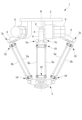
- FIG. 1 is a front view schematically showing a parallel link robot according to an embodiment of the present disclosure.
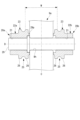
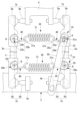
- FIG. 2 is a front view schematically showing an attached state of the biasing mechanism of the connection structure in a pair of links of the parallel link robot of FIG. 1; 2 is a sectional view showing the shapes of a mounting pin and a pair of bushes included in one link of the parallel link robot of FIG. 1.
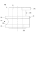
- FIG. 4 is a side view showing the shape of one bush of the connection structure shown in FIG. 3.
- FIG. 5 is a front view showing the shape of the bush shown in FIG. 4.
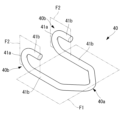
- FIG. 3 is a perspective view showing the shape of a hook of the connection structure shown in FIG. 2.
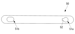
- FIG. 3 is a front view showing the shape of a connecting member of the connecting structure shown in FIG. 2.
- FIG. 3 is a diagram illustrating a procedure for attaching a connecting member in the connecting structure shown in FIG. 2.
- FIG. 3 is a diagram illustrating a procedure for attaching a connecting member in the connecting structure shown in FIG. 2.
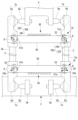
- FIG. 3 is a front view schematically showing how the connecting members are attached in the connecting structure shown in FIG. 2.
- FIG. FIG. 3 is a front view schematically showing the shape of a biasing mechanism in a first modified example of the connection structure shown in FIG. 2; 3 is a schematic diagram showing the shape of one bush in a second modification of the connection structure shown in FIG. 2.
- the parallel link robot 1 includes, for example, as shown in FIG. 1, a base part 2 that is suspended and fixed to a ceiling or the like. Further, the parallel link robot 1 includes a movable part 3 arranged below the base part 2 at a distance. Further, the parallel link robot 1 includes three arms 4 supported rotatably around three horizontal axes A with respect to the base portion 2. Further, the parallel link robot 1 includes, for each arm 4, a pair of mutually parallel links 5a and 5b that connect each arm 4 and the movable part 3. Further, the parallel link robot 1 includes connection structures 10 and 10' extending between each pair of links 5a and 5b.
- the base portion 2 includes three servo motors 6 for driving the three arms 4, respectively.
- the servo motors 6 are arranged at equal intervals in the circumferential direction around an axis B that passes through the center of the base portion 2 and extends in the vertical direction.
- the servo motors 6 each have a rotation drive shaft (not shown) that is rotated around a horizontal axis A.
- Each arm 4 has its base end connected to the rotational drive shaft of the corresponding servo motor 6, and is rotatable around the axis A with respect to the base portion 2.
- the parallel link robot 1 includes a pair of ball joints 7a and 7b that connect the tips of each arm 4 and links 5a and 5b.
- Each ball joint 7a, 7b includes a ball stud 8a, 8b and a socket 9a, 9b.
- the ball studs 8a, 8b are attached to both outer sides in the direction of the axis A (see FIG. 1), sandwiching the tip of each arm 4.
- Each pair of links 5a, 5b is provided with a socket 9a, 9b at one end in the longitudinal axis C direction.
- the sockets 9a and 9b are fitted into the ball studs 8a and 8b at the tips of the corresponding arms 4 so as to be sandwiched from both sides in the direction of the axis A, respectively.
- each socket 9a, 9b includes a mounting pin 29 that protrudes in a direction perpendicular to the longitudinal axis C, as shown in FIGS. 2 and 3.
- the mounting pins 29 are press-fitted into pin holes 9h that pass through the sockets 9a and 9b in a direction perpendicular to the longitudinal axis C, and protrude on both sides of the longitudinal axis C. Further, the mounting pin 29 is press-fitted from one side of the pin hole 9h until it abuts against a flange-shaped positioning portion 29p provided at an intermediate position in the length direction.
- the protruding amounts of the mounting pins 29 protruding from both sides of the outer peripheral surfaces of the sockets 9a and 9b are made equal to each other. Further, in the assembled state, the mounting pin 29 extends along an axis D that is perpendicular to a plane that includes the longitudinal axis C of the two links 5a and 5b.
- each link 5a, 5b is provided with a socket 9a', 9b' similar to the one end at the other end in the direction of the longitudinal axis C, respectively.
- the sockets 9a', 9b' constitute ball joints 7a', 7b' together with ball studs 8a', 8b' provided on the movable part 3.
- the sockets 9a', 9b' like the sockets 9a, 9b, are provided with mounting pins 29 press-fitted into the pin holes 9h and 9h, respectively.
- the movable portion 3 includes a pair of parallel flat plate-shaped attachment portions 3w that protrude radially outward from the outer peripheral surface at positions corresponding to each pair of links 5a, 5b.
- Ball studs 8a', 8b' are attached to the outside of each pair of attachment portions 3w.
- the sockets 9a', 9b' at the other end of each link 5a, 5b fit into the ball studs 8a', 8b' in such a manner that they are sandwiched from both outer sides in the direction of the axis A, respectively.
- connection structures 10 and 10' according to this embodiment will be explained.
- the three pairs of links 5a, 5b and the three upper and lower connection structures 10, 10' each have the same configuration. Therefore, in the following, the configuration of a pair of links 5a, 5b and one connection structure 10 will be described as an example.
- connection structure 10 includes bushes 20a and 20b attached to each socket 9a and 9b. Further, as shown in FIG. 2, the connection structure 10 includes a biasing mechanism 30 and a connection member 50 that span between the sockets 9a and 9b and connect them.
- the bushes 20a and 20b are manufactured by, for example, injection molding a resin material such as silicone resin.
- the bushes 20a and 20b each have a cylindrical shape with a hollow hole 21, as shown in FIGS. 4 to 7.
- the hollow hole 21 has a circular cross section into which the mounting pin 29 is rotatably fitted.
- the hollow hole 21 of the bush 20a is provided with a relief portion corresponding to a positioning portion 29p provided on the mounting pin 29.
- the bushes 20a, 20b each include a first cylindrical portion 22a, 22b on one side in the axial direction, and a second cylindrical portion 23 on the other side in the axial direction, respectively.
- the first cylindrical portions 22a, 22b are provided with claws (claw portions) 24a, 24b in the form of portions of the circumferential direction protruding outward in the radial direction, at the axial ends of the cylindrical portions.
- the claws 24a and 24b will be described later.
- the second cylindrical portion 23 has an outer diameter larger than the outer diameter of the first cylindrical portions 22a and 22b.
- the second cylindrical portion 23 includes a groove portion 25 recessed in the radial direction at an intermediate position in the respective axial directions.
- the second cylindrical portion 23 includes flange portions 26 that project outward in the radial direction from the groove portion 25 on both sides of the groove portion 25 in the axial direction.
- the groove portion 25 includes a semicircular arc-shaped curved groove portion 25a and a pair of mutually parallel linear groove portions 25b that are continuous to both ends of the curved groove portion 25a.
- the groove portion 25 and the collar portion 26 have a non-circular cross-sectional shape.
- the biasing mechanism 30 includes a coil spring (elastic body) 31 and two hooks 40 arranged at both ends of the coil spring 31, as shown in FIG.
- the hook 40 is connected to both ends of the coil spring 31 by hooking the hook portions 31a at both ends of the coil spring 31, respectively.
- the hook portions 31a each have a shape obtained by bending a wire forming the coil spring 31 into a hook shape. Further, the coil spring 31 has a spring constant sufficient to apply an appropriate amount of preload to the ball joints 7a and 7b.
- the hook 40 is a member made by bending and deforming a metal round bar. Moreover, this metal round bar has an outer diameter dimension equivalent to the groove width of the groove portions 25 of the bushes 20a, 20b.
- the hook 40 includes a first connecting portion 40a whose longitudinal center is curved along an arbitrary first plane F1.
- the hook 40 also includes a pair of second connecting portions 40b whose lengthwise ends are curved along a second plane F2 perpendicular to the first plane F1.
- Each second connecting portion 40b includes a pair of linear portions 41b extending parallel to each other at both ends of a semicircular arc-shaped curved portion 41a.
- each of the second connecting portions 40b has a shape that matches the shape of the groove portion 25 around the axis D.
- the pair of second connecting parts 40b are hooked into the grooves 25 of the two bushes 20a and 20b attached to the socket 9a, respectively. Then, the curved part 41a and the two straight parts 41b of the second connecting part 40b come into close contact with the bottom of each groove part 25. That is, the curved part 41a of the hook 40 is in close contact with the curved groove part 25a, and the straight part 41b is in close contact with the straight groove part 25b. Thereby, the two bushes 20a, 20b and each hook 40 are integrally connected so as not to rotate relative to each other around the axis D of the mounting pin 29.
- the coil spring 31 hooks the hook portion 31a onto the first connecting portion 40a of the hook 40, which has the second connecting portion 40b hooked onto the bushes 20a, 20b.
- the first connecting portion 40a of the hook 40 extends parallel to the axis D of the mounting pin 29. Therefore, the hook portions 31a at both ends of the coil spring 31 are hooked on the two hooks 40 so as to be rotatable around axes parallel to the axis D, respectively.
- the connecting member 50 is a long strip-shaped member formed by punching out a flat metal plate.
- One connecting member 50 is arranged on both sides of the sockets 9a and 9b in the direction of the axis D. Furthermore, each connecting member 50 is provided with attachment holes 51a and 51b that penetrate in the thickness direction near both ends in the length direction.
- the attachment hole 51a has an opening shape that allows it to pass through the first cylindrical portion 22a including the claw 24a of the bush 20a in the axial direction of the first cylindrical portion 22a.
- the pawl 24a has a width dimension smaller than the diameter of the cylindrical portion of the first cylindrical portion 22a, and a length dimension that protrudes in the radial direction to a position equivalent to the outer shape of the flange portion 26.
- the claw 24a has a flat plate shape with a predetermined thickness. The claw 24a extends from the outer surface of the cylindrical portion of the first tube portion 22a in a direction different from the longitudinal direction of the straight groove portion 25b, for example, in a direction forming an angle of 120°.
- the attachment hole 51a has a notch 52 in a part of the circumferential direction of a circular opening shape with an inner diameter slightly larger than the outer diameter of the cylindrical portion of the first cylinder portion 22a.
- the size and shape of the notch 52 are such that it can pass through the claw 24a, for example, a similar shape that is slightly larger than the claw 24a.
- the attachment hole 51b also has an elongated opening shape that can penetrate the first cylindrical portion 22b including the claw 24b of the bush 20b in the axial direction of the first cylindrical portion 22b.
- the claw 24b has a width dimension equivalent to the diameter of the cylindrical portion of the first tube portion 22b, and a length dimension that is larger than the outer diameter of the collar portion 26 and projects in the radial direction. Further, the claw 24b has a flat plate shape with a predetermined thickness. The claw 24b extends from the outer surface of the cylindrical portion of the first tube portion 22b in a direction different from the longitudinal direction of the straight groove portion 25b, for example, in a direction forming an angle of 30°.
- the attachment hole 51b has a width dimension that is slightly larger than the width dimension of the claw 24b, and a length dimension that is slightly larger than the dimension of the first cylindrical portion 22b in the length direction of the claw 24b.
- the attachment hole 51b extends in the longitudinal axis direction of the connecting member 50, and passes through the cylindrical portion of the first cylindrical portion 22b so as to be movable in the longitudinal axis direction of the connecting member 50.
- the connecting member 50 allows the first cylindrical parts 22a and 22b, which are arranged on the same side of the sockets 9a and 9b in the direction of the axis D, to pass through the mounting holes 51a and 51b, respectively. Further, in this case, the phases of the length direction of the claws 24a, 24b passing through the attachment holes 51a, 51b and the length direction of the notch 52 around the axis D are different.
- the parallel link robot 1 is assembled as follows. For assembly, a base unit, a movable part 3, three pairs of links 5a, 5b, and three connecting structures 10, 10' are prepared.
- the base unit includes three arms 4 and ball studs 8a, 8b assembled from a base part 2.
- Each link 5a, 5b has a socket 9a, 9b and a mounting pin 29 attached to one end, and a socket 9a', 9b' and a mounting pin 29 attached to the other end.
- two hooks 40 are connected to each of the coil springs 31 of the connection structures 10 and 10'. Specifically, the hook portions 31a on both sides of the coil spring 31 are hooked on the first connecting portions 40a of the two hooks 40, respectively.
- a pair of bushes 20a, 20b is attached to the attachment pin 29 of each socket 9a, 9b of each link 5a, 5b.
- the bushes 20a and 20b are brought close to each other from both sides of the sockets 9a and 9b, and the mounting pin 29 is fitted into the hollow hole 21.
- the pair of bushes 20a and 20b are rotatably mounted around the axis D of the same mounting pin 29.
- a pair of bushes 20a, 20b is attached to the attachment pin 29 of each socket 9a', 9b' of each link 5a, 5b.
- bushes 20a and 20b are attached to both ends of the attachment pin 29 of each socket 9a' and 9b', respectively, so as to be rotatable around the axis D of each attachment pin 29.
- the pair of second connecting portions 40b of the hook 40 on one side of the connecting structure 10 are hooked into the grooves 25 of the bushes 20a, 20b attached to the socket 9a. Further, the pair of second connecting portions 40b of the hook 40 on the other side are hooked on the groove portions 25 of the bushes 20a, 20b attached to the socket 9b. Similarly, the hook 40 on one side of the connecting structure 10' is hooked into the groove 25 of the bushes 20a, 20b attached to the socket 9a'. Further, the hook 40 on the other side is hooked into the groove portion 25 of the bushes 20a, 20b attached to the socket 9b'.
- one side of the pair of links 5a, 5b for example, the sockets 9a, 9a' of the link 5a
- the sockets 9a, 9a' of the link 5a is brought close to the ball studs 8a, 8a', respectively.
- the sockets 9a, 9a' are fitted into the ball studs 8a, 8a' from the outside in the axis A direction.
- the user holds the link 5b on the other side and pulls the two coil springs 31 in a stretching direction to widen the distance between the links 5a and 5b.
- the sockets 9b and 9b' of the link 5b are simultaneously fitted into the ball studs 8b and 8b' from the outside in the direction of the axis A, respectively.
- the ball studs 8a, 8b are sandwiched in the axis A direction by the pair of sockets 9a, 9b.
- the ball studs 8a' and 8b' are sandwiched in the axis A direction by a pair of sockets 9a' and 9b'.
- the pair of links 5a and 5b are connected by the two biasing mechanisms 30 and attached to the arm 4 and the movable part 3.
- the two second connecting portions 40b of one hook 40 are caught in the grooves 25 of the two bushes 20a, 20b sandwiching the sockets 9a, 9b.
- the hook 40 integrally connects the pair of bushes 20a, 20b.
- each groove portion 25 is positioned to sandwich the second connecting portion 40b of the hook 40 in the axial direction of the second cylindrical portion 23.
- the bushes 20a and 20b restrict movement of the hook 40 along the axial direction of the mounting pin 29.
- the hook 40 prevents the bushes 20a and 20b from falling off the mounting pin 29. That is, the bushes 20a, 20b and the hook 40 can rotate integrally around the axis D of the attachment pin 29, and do not move relative to each other in other directions. The same applies to the two bushes 20a and 20b sandwiching the sockets 9a' and 9b'.
- a connecting member 50 is attached between the links 5a and 5b.
- the first cylindrical portion 22a of the bush 20a attached to one link 5a is passed through the attachment hole 51a of the connecting member 50.
- the connecting member 50 is rotated around the axis D of the bush 20a.
- the attachment hole 51a and the claw 24a are out of phase, so that the connecting member 50 is attached to the first cylindrical portion 22a of the bush 20a without coming off.
- the connecting member 50 is rotated around the axis D of the bush 20a until the attachment hole 51b coincides with the first cylindrical portion 22b of the bush 20b. In this state, the phase of the claw 24b of the bush 20b does not match the length direction of the attachment hole 51b of the connecting member 50.
- the claw 24b of the bush 20b of the coupling structure 10' extends in a different direction from the claw 24b of the coupling structure 10. Thereby, when the bush 20b is passed through the attachment hole 51b of the connection member 50 of the connection structure 10', the coil spring 31 does not interfere with surrounding members.
- the remaining two pairs of links 5a and 5b can be assembled in the same manner, thereby completing the assembly of the parallel link robot 1.
- the connecting member 50 that regulates the spread of the interval can be assembled or removed without using tools or jigs.
- the bushes 20a and 20b that support the connecting member 50 with respect to the pair of links 5a and 5b are held in predetermined positions by the biasing mechanism 30. That is, the claws 24a, 24b and the attachment holes 51a, 51b of the connecting member 50 are positioned in a phase that prevents the connecting member 50 from falling off. Thereby, it is possible to prevent the connecting member 50 from falling off unintentionally when the links 5a, 5b are operated.
- one attachment hole 51a of the connecting member 50 has a circular cross section, and the first cylindrical portion 22a passing through the attachment hole 51a does not move relative to the radial direction within the attachment hole 51a. Therefore, even if the parallel link robot 1 operates, no rattling occurs between the connecting member 50 and the bush 20a.
- one of the attachment holes 51b of the connecting member 50 is a long hole, the first cylindrical portion 22b is allowed to be displaced to some extent while passing through the attachment hole 51b. Therefore, even if the distance between the links 5a, 5b decreases due to aging of the ball joints 7a, 7b, there is an advantage that the shortening can be tolerated.
- the two hooks 40 are connected to the hook portions 31a at both ends of the coil spring 31 so as to be rotatable about an axis parallel to the axis D.
- at least one of the hooks 40 may be integrally fixed to the hook portion 31a.
- the hook 40 on the bush 20a side may be fixed to the hook portion 31a by welding or the like. If the hook 40 on the bush 20b side and the coil spring 31 can rotate relative to each other, the phase of the claw 24b can be easily matched with the phase of the mounting hole 51b.
- two hooks 40 can be welded to the hook portions 31a on both sides of the coil spring 31, respectively.
- the connecting member 50 is connected to the bushes 20a and 20b.
- the hooks 40 welded on both sides may be hooked onto the bushes 20a, 20b.
- the connecting member 50 is attached by simultaneously aligning the phases of the claws 24a, 24b with the phases of the two attachment holes 51a, 51b of the connecting member 50. Then, the bushes 20a and 20b are rotated around the axis D to shift the phase. After that, the biasing mechanism 30 is attached to restrict the rotation of the bushes 20a, 20b. Thereby, the coil spring 31 and the two hooks 40 can be handled as one. Moreover, when the space for attaching the connection structure 10 is narrow, the assembly work can be facilitated.
- the phase of the claws 24a, 24b with respect to the straight groove portion 25b can be freely set. Therefore, by arranging the claws 24b in a phase that is significantly shifted from the longitudinal direction of the attachment hole 51b, it is possible to more reliably prevent the connecting member 50 from falling off.
- the bush 20b can be the same as the bush 20a. Thereby, the number of parts can be reduced, and manufacturing costs can also be reduced by making parts common. Further, during assembly work, there is no need to worry about the type of bushing, and work efficiency can be improved. In this case, by maintaining the shape of the attachment hole 51b as a long hole, it is possible to cope with changes in the distance between the links 5a and 5b due to aging or the like.
- the relative rotation between the two is regulated by the contact between the straight part 41b of the hook 40 and the straight groove part 25b of the bushes 20a and 20b.
- the bushes 20a, 20b may not have the straight groove portion 25b.
- the groove 25 of the bush 20b has a non-circular cross-sectional shape such as an ellipse.
- the curved portion 41a of the hook 40 is curved into a shape that matches the groove portions 25 of the bushes 20a, 20b.
- the elastic restoring force of the coil spring 31 restricts the rotation of the bush 20b about the axis D.
- the same effect can be obtained by using the same configuration for the bush 20a and the hook 40 connected to the bush 20a.
- the cross-sectional shape of the groove portions 25 of the bushes 20a, 20b may be non-circular other than elliptical. Any cross-sectional shape may be adopted as long as rotation about the axis D is restricted by bringing the curved portion 41a of the hook 40 into close contact with the hook 40.
- the cross-sectional shape of the groove portions 25 of the bushes 20a, 20b may be circular and eccentric with respect to the axis D. Also in this case, by bringing the curved portion 41a of the hook 40 into close contact with each other, rotation of the bushes 20a and 20b about the axis D can be restricted.
- one mounting pin 29 is press-fitted into each of the sockets 9a and 9b with both ends protruding in the direction of the axis D.
- two mounting pins 29 may be press-fitted into the sockets 9a and 9b from both outsides in the direction of the axis D.
- the mounting pin 29 may be formed into a simple round bar shape, and may be press-fitted from both outer sides in the direction of the axis D to a depth of about half of the pin hole 9h.
- connection structure 10 was attached between the sockets 9a and 9b, and the connection structure 10' was attached between the sockets 9a' and 9b'.
- the connecting structure 10' attached between the sockets 9a' and 9b' at the other ends of the links 5a and 5b may be omitted.
- the coil spring 31 of the connection structure 10 has a spring constant sufficient to hold the four ball joints 7a, 7b, 7a', and 7b'.
Landscapes
- Engineering & Computer Science (AREA)
- Mechanical Engineering (AREA)
- Robotics (AREA)
- General Engineering & Computer Science (AREA)
- Health & Medical Sciences (AREA)
- General Health & Medical Sciences (AREA)
- Orthopedic Medicine & Surgery (AREA)
- Pivots And Pivotal Connections (AREA)
- Transmission Devices (AREA)
Abstract
Description
したがって、2本のリンク間の距離を規制する部材の脱落を防止し、工具を用いずに組み付けおよび取り外しを容易にすることが望まれている。
本実施形態に係るパラレルリンクロボット1は、例えば、図1に示すように、天井等に吊り下げて固定される基礎部2を備える。また、パラレルリンクロボット1は、基礎部2の下方に間隔を空けて配置される可動部3を備える。さらに、パラレルリンクロボット1は、基礎部2に対して、水平な3本の軸線A回りにそれぞれ回転可能に支持された3つのアーム4を備える。また、パラレルリンクロボット1は、アーム4毎に、各アーム4と可動部3とを接続する2本一対の互いに平行なリンク5a,5bを備える。さらに、パラレルリンクロボット1は、各対のリンク5a,5b間に掛け渡された連結構造10,10´を備える。
サーボモータ6は、それぞれ水平な軸線A回りに回転させられる回転駆動軸(図示略)を有する。
ボールスタッド8a,8bは、各アーム4の先端を挟んだ軸線A方向(図1参照)の両外側に取り付けられている。
本実施形態において、3対のリンク5a,5bおよび上下3つずつの連結構造10,10´は、それぞれ同様の構成を有している。このため、以下においては、一対のリンク5a,5bおよび1つの連結構造10の構成を例に挙げて説明をする。
中空孔21は、取付ピン29を回転可能に嵌合させる円形横断面を有する。また、ブッシュ20aの中空孔21には、取付ピン29に設けられた位置決め部29pに対応する逃げ部が設けられている。これにより、ブッシュ20a,20bを取付ピン29の両端に取り付ける際の組み合わせは、一義的に決まる。
爪24a,24bについては後述する。
引掛部31aは、それぞれコイルバネ31を構成する線材を鉤状に折り曲げた形状を有する。また、コイルバネ31は、ボールジョイント7a,7bに対して、適当な大きさの予圧を付与することができるだけのバネ定数を有する。
また、各第2連結部40bは、それぞれ溝部25の軸線D回りの形状に一致する形態を有する。
爪24aは、第1筒部22aの円筒状部分の直径よりも小さい幅寸法と、鍔部26の外形と同等位置まで径方向に突出する長さ寸法とを有する。また、爪24aは、所定の厚さを有する平板状である。爪24aは、第1筒部22aの円筒状部分の外面から直線溝部25bの長さ方向とは異なる方向、例えば120°の角度をなす方向に延びている。
また、この場合に、取付孔51a,51bを貫通した爪24a,24bの長さ方向と、切欠き52の長さ方向との軸線D回りの位相は相違する。
組立にあたっては、ベースユニット、可動部3、3対のリンク5a,5bおよび3つずつの連結構造10,10´を用意する。ベースユニットは、基礎部2から3本のアーム4およびボールスタッド8a,8bが組み付けられたものである。各リンク5a,5bは、一端にソケット9a,9bおよび取付ピン29、他端にソケット9a´,9b´および取付ピン29を取り付けたものである。
パラレルリンクロボット1を組み立てるには、まず、連結構造10,10´のコイルバネ31に、それぞれ2つのフック40を連結する。具体的には、コイルバネ31の両側の引掛部31aを、それぞれ2つのフック40の第1連結部40aに引っ掛ける。
同様に、各リンク5a,5bの各ソケット9a´,9b´の取付ピン29に一対のブッシュ20a,20bを取り付ける。また、各ソケット9a´,9b´の取付ピン29の両端に、それぞれブッシュ20a,20bを各取付ピン29の軸線D回りに回転可能に取り付ける。
同様に、連結構造10´の一側のフック40を、ソケット9a´に取り付けたブッシュ20a,20bの溝部25に引っ掛ける。また、他側のフック40を、ソケット9b´に取り付けたブッシュ20a,20bの溝部25に引っ掛ける。
この状態では、ソケット9a,9bを挟んだ2つのブッシュ20a,20bの各溝部25に1つのフック40の2つの第2連結部40bが引っ掛かる。これにより、フック40が、一対のブッシュ20a,20bを一体的に接続する。
図10に示すように、一方のリンク5aに取り付けたブッシュ20aの第1筒部22aを連結部材50の取付孔51aに貫通させる。取付孔51aの切欠き52の長さ方向を第1筒部22aの爪24aの位相に一致させることにより、容易に貫通させることができる。そして、取付孔51aを爪24aが通過した後に、連結部材50をブッシュ20aの軸線D回りに回転させる。これにより、取付孔51aと爪24aとの位相がずれるので、連結部材50がブッシュ20aの第1筒部22aに外れないように取り付く。
同様にして、連結構造10´の連結部材50を、ソケット9a´,9b´の取付ピン29に取り付けたブッシュ20a,20b間に掛け渡す。図10に示す例では、連結構造10´のブッシュ20bの爪24bは、連結構造10の爪24bとは異なる方向に延びている。これにより、連結構造10´の連結部材50の取付孔51bに、ブッシュ20bを貫通させる際、コイルバネ31を周辺部材と干渉させずに済む。
残りの2対のリンク5a,5bについても同様にして組み付けることができ、これにより、パラレルリンクロボット1の組み立てが完了する。
さらに、一対のリンク5a,5bに対して連結部材50を支持するブッシュ20a,20bは、付勢機構30によって所定の姿勢に保持される。すなわち、爪24a,24bと連結部材50の取付孔51a,51bとが、連結部材50の脱落を防止する位相に位置する。これにより、リンク5a,5bの動作時などに、連結部材50が意図せず脱落してしまうことを防止することができる。
これにより、コイルバネ31と2つのフック40とを一体的に扱うことができる。また、連結構造10を取り付けるためのスペースが狭い場合に、組付け作業を容易にすることができる。
特に、直線溝部25bに対する爪24a,24bの位相を同じにすれば、ブッシュ20bとして、ブッシュ20aと同一のものを使用することができる。これにより、部品点数を削減することができ、部品を共通化することにより製造コストを低減することもできる。また、組立作業の際、ブッシュの種類を気にせずに済み、作業効率を向上することもできる。
この場合に、取付孔51bの形状については長孔状を維持することにより、経年変化等によるリンク5a,5b間距離の変化に対応できる。
これにより、付勢機構30が連結された状態においては、コイルバネ31の弾性復元力により、ブッシュ20bの軸線D回りの回転が規制される。その結果、上記と同様に、ブッシュ20bの爪24bと連結部材50の取付孔51bとの軸線D回りの位相がずれた状態を維持することができる。
ブッシュ20aおよびブッシュ20aに連結されるフック40についても同様の構成とすることにより、同等の効果を得ることができる。
例えば、ブッシュ20a,20bの溝部25の横断面形状は、軸線Dに対して偏心した円形であってもよい。これによっても、フック40の湾曲部41aを密着させることにより、ブッシュ20a,20bの軸線D回りの回転を規制することができる。
例えば、取付ピン29を単純な丸棒状とし、軸線D方向の両外側から、それぞれピン孔9hの半分程度の深さまで圧入することとしてもよい。
この場合には、連結構造10のコイルバネ31が、4つのボールジョイント7a,7b,7a´,7b´を保持するだけのバネ定数を有していればよい。
2 基礎部
3 可動部
4 アーム
5a,5b リンク
10,10´ 連結構造
20a,20b ブッシュ
24a,24b 爪(爪部)
25 溝部
30 付勢機構
31 コイルバネ(弾性体)
40 フック
50 連結部材
51a,51b 取付孔
C 長手軸
D 軸線
Claims (7)
- 長手軸を有し、平行に間隔をあけて動作する2本のリンクを相互に連結する連結構造であって、
各前記リンクに、2つの前記長手軸を含む平面に直交する軸線回りにそれぞれ回転可能に取り付けられるブッシュと、
2つの前記リンクの前記ブッシュ間に掛け渡され、2つの該ブッシュに相互に近接する方向に弾性復元力を加える付勢機構と、
各前記ブッシュを前記軸線方向に貫通可能な2つの取付孔を有し、前記ブッシュ間の距離を所定の距離以下に規制する連結部材とを備え、
前記ブッシュが前記軸線方向の端部の周方向の一部において径方向外方に突出する爪部を備え、
各前記取付孔が、各前記ブッシュの前記爪部に一致する前記軸線回りの所定の取付位相においてのみ、各前記ブッシュの貫通を許容する形状に形成され、
各前記ブッシュの各前記軸線回りの位相が、前記弾性復元力によって、前記取付位相に一致しない位相に規制される連結構造。 - 前記ブッシュが、前記リンクを前記軸線方向に挟んだ両側に配置され、
前記付勢機構が、前記リンクを挟んだ両側の前記ブッシュに接続されている請求項1に記載の連結構造。 - 前記付勢機構が、前記弾性復元力を発生する弾性体と、該弾性体の両端に配置され、前記ブッシュに引っ掛けるフックとを備える請求項1に記載の連結構造。
- 前記フックおよび前記ブッシュが、前記フックを引っ掛けた状態において、前記軸線回りの相対回転が禁止された状態に維持される形状を有する請求項3に記載の連結構造。
- 前記弾性体の少なくとも一端と前記フックとが、前記軸線に平行な軸線回りに相互に回転可能に接続されている請求項4に記載の連結構造。
- 前記ブッシュの外周面の前記軸線方向の途中位置に、径方向内方に凹み、前記フックを引っ掛ける溝部を備える請求項5に記載の連結構造。
- 基礎部と、
該基礎部と間隔を空けて配置される可動部と、
前記基礎部に揺動可能に接続された複数のアームと、
該アームと前記可動部とを連結する互いに平行な長手軸を有する2本一対のリンクと、
一対の該リンク間に設けられる、請求項1に記載の連結構造とを備えるパラレルリンクロボット。
Priority Applications (6)
| Application Number | Priority Date | Filing Date | Title |
|---|---|---|---|
| DE112022006651.2T DE112022006651T5 (de) | 2022-05-12 | 2022-05-12 | Verbindungsstruktur und parallelgliederroboter |
| JP2024520194A JP7794959B2 (ja) | 2022-05-12 | 2022-05-12 | 連結構造およびパラレルリンクロボット |
| PCT/JP2022/020116 WO2023218618A1 (ja) | 2022-05-12 | 2022-05-12 | 連結構造およびパラレルリンクロボット |
| US18/857,637 US12403586B1 (en) | 2022-05-12 | 2022-05-12 | Connection structure and parallel link robot |
| CN202280095636.1A CN119136955A (zh) | 2022-05-12 | 2022-05-12 | 连接结构以及并联连杆机器人 |
| TW112115418A TW202408754A (zh) | 2022-05-12 | 2023-04-25 | 連結結構以及平行連桿機器人 |
Applications Claiming Priority (1)
| Application Number | Priority Date | Filing Date | Title |
|---|---|---|---|
| PCT/JP2022/020116 WO2023218618A1 (ja) | 2022-05-12 | 2022-05-12 | 連結構造およびパラレルリンクロボット |
Publications (1)
| Publication Number | Publication Date |
|---|---|
| WO2023218618A1 true WO2023218618A1 (ja) | 2023-11-16 |
Family
ID=88730171
Family Applications (1)
| Application Number | Title | Priority Date | Filing Date |
|---|---|---|---|
| PCT/JP2022/020116 Ceased WO2023218618A1 (ja) | 2022-05-12 | 2022-05-12 | 連結構造およびパラレルリンクロボット |
Country Status (6)
| Country | Link |
|---|---|
| US (1) | US12403586B1 (ja) |
| JP (1) | JP7794959B2 (ja) |
| CN (1) | CN119136955A (ja) |
| DE (1) | DE112022006651T5 (ja) |
| TW (1) | TW202408754A (ja) |
| WO (1) | WO2023218618A1 (ja) |
Citations (4)
| Publication number | Priority date | Publication date | Assignee | Title |
|---|---|---|---|---|
| JP2004142791A (ja) * | 2002-10-24 | 2004-05-20 | Ricoh Co Ltd | 連結具及び該連結具を有する物品運搬装置 |
| JP2011194534A (ja) * | 2010-03-23 | 2011-10-06 | Kawasaki Heavy Ind Ltd | ロボット |
| JP2013158878A (ja) * | 2012-02-03 | 2013-08-19 | Yaskawa Electric Corp | パラレルリンクロボット |
| JP2014073541A (ja) * | 2012-10-03 | 2014-04-24 | Yamaha Motor Co Ltd | アーム部材およびこのアーム部材を備える産業用ロボット |
Family Cites Families (12)
| Publication number | Priority date | Publication date | Assignee | Title |
|---|---|---|---|---|
| SE513328C2 (sv) * | 1998-11-11 | 2000-08-28 | Abb Ab | Manipulator och förfarande vid framställning av en manipulator |
| EP2098339B1 (en) * | 2006-11-15 | 2015-06-10 | Murata Machinery, Ltd. | Parallel mechanism |
| DE102007004379A1 (de) * | 2007-01-29 | 2008-07-31 | Robert Bosch Gmbh | Vorrichtung zum Bewegen und Positionieren eines Gegenstandes im Raum |
| JP4725748B2 (ja) | 2007-10-15 | 2011-07-13 | 村田機械株式会社 | パラレルリンクのリンク機構 |
| JP2009248285A (ja) * | 2008-04-10 | 2009-10-29 | Murata Mach Ltd | パラレルメカニズム |
| DE102008062958A1 (de) * | 2008-12-23 | 2010-07-01 | Multivac Sepp Haggenmüller Gmbh & Co. Kg | Roboter, insbesondere einer Verpackungsmaschine zugeordneter Roboter |
| CN102069495B (zh) * | 2009-11-23 | 2014-01-22 | 鸿富锦精密工业(深圳)有限公司 | 并联机器人 |
| JP5408211B2 (ja) * | 2011-09-06 | 2014-02-05 | 株式会社安川電機 | パラレルリンクロボット、パラレルリンクロボットシステムおよびパラレルリンクロボットの制御方法 |
| JP5674734B2 (ja) * | 2012-08-31 | 2015-02-25 | ファナック株式会社 | ボールジョイントにより接続されたパラレルリンクロボット |
| KR101413152B1 (ko) * | 2013-02-27 | 2014-07-01 | 부산대학교 산학협력단 | 마찰감소용 볼을 구비한 구 관절 및 델타로봇 |
| JP5682642B2 (ja) * | 2013-03-05 | 2015-03-11 | 株式会社安川電機 | パラレルリンクロボット |
| JP2017052040A (ja) * | 2015-09-08 | 2017-03-16 | 川崎重工業株式会社 | ロボット |
-
2022
- 2022-05-12 JP JP2024520194A patent/JP7794959B2/ja active Active
- 2022-05-12 WO PCT/JP2022/020116 patent/WO2023218618A1/ja not_active Ceased
- 2022-05-12 CN CN202280095636.1A patent/CN119136955A/zh active Pending
- 2022-05-12 US US18/857,637 patent/US12403586B1/en active Active
- 2022-05-12 DE DE112022006651.2T patent/DE112022006651T5/de active Pending
-
2023
- 2023-04-25 TW TW112115418A patent/TW202408754A/zh unknown
Patent Citations (4)
| Publication number | Priority date | Publication date | Assignee | Title |
|---|---|---|---|---|
| JP2004142791A (ja) * | 2002-10-24 | 2004-05-20 | Ricoh Co Ltd | 連結具及び該連結具を有する物品運搬装置 |
| JP2011194534A (ja) * | 2010-03-23 | 2011-10-06 | Kawasaki Heavy Ind Ltd | ロボット |
| JP2013158878A (ja) * | 2012-02-03 | 2013-08-19 | Yaskawa Electric Corp | パラレルリンクロボット |
| JP2014073541A (ja) * | 2012-10-03 | 2014-04-24 | Yamaha Motor Co Ltd | アーム部材およびこのアーム部材を備える産業用ロボット |
Also Published As
| Publication number | Publication date |
|---|---|
| US12403586B1 (en) | 2025-09-02 |
| JP7794959B2 (ja) | 2026-01-06 |
| TW202408754A (zh) | 2024-03-01 |
| JPWO2023218618A1 (ja) | 2023-11-16 |
| CN119136955A (zh) | 2024-12-13 |
| DE112022006651T5 (de) | 2025-01-23 |
| US20250276442A1 (en) | 2025-09-04 |
Similar Documents
| Publication | Publication Date | Title |
|---|---|---|
| US20240165791A1 (en) | Robot arm, manufacturing method therefor, and robot | |
| EP1464871B1 (en) | Two-arm belt tensioner | |
| US20170014994A1 (en) | Parallel link mechanism and link actuation device | |
| WO2018229889A1 (ja) | マニピュレータ | |
| US20090065994A1 (en) | Reconfigurable Clamp and Method of Use Thereof | |
| JP2021171913A (ja) | 異なる形状およびサイズのアイテムまたはコンポーネントを操作するための把持デバイス | |
| WO2023218618A1 (ja) | 連結構造およびパラレルリンクロボット | |
| US11213128B2 (en) | Motion furniture mechanism with pre-aligned linkage member | |
| KR101222113B1 (ko) | 스프링 조립체 | |
| KR102480328B1 (ko) | 어셈블리를 연결하는 상보적 체결 요소를 갖는 로봇 | |
| CN100484799C (zh) | 变速杆装置 | |
| JP6061981B2 (ja) | クランプ器具 | |
| JP4205682B2 (ja) | 弾性軸継手 | |
| WO2014178202A1 (ja) | 球面ジョイント機構及びこの球面ジョイント機構を備えた組立て装置 | |
| CN109139858A (zh) | 可调整驱动齿轮组装件 | |
| US20250144787A1 (en) | Parallel link robot | |
| JP3231011B2 (ja) | 長尺部材の固定構造 | |
| US1166206A (en) | Rod connection. | |
| CN118809054B (zh) | 一种汽车钣金装夹工作台 | |
| CN222450353U (zh) | 关节主体及机器人 | |
| CN115190833B (zh) | 工件把持机构 | |
| JP2020085159A (ja) | チェーン | |
| US20160313756A1 (en) | Operating pedal device for vehicle and method for manufacturing operating pedal device for vehicle | |
| JP2009248285A (ja) | パラレルメカニズム | |
| JP3633457B2 (ja) | フロントピラー用汎用クランプ装置 |
Legal Events
| Date | Code | Title | Description |
|---|---|---|---|
| 121 | Ep: the epo has been informed by wipo that ep was designated in this application |
Ref document number: 22941697 Country of ref document: EP Kind code of ref document: A1 |
|
| ENP | Entry into the national phase |
Ref document number: 2024520194 Country of ref document: JP Kind code of ref document: A |
|
| WWE | Wipo information: entry into national phase |
Ref document number: 112022006651 Country of ref document: DE |
|
| WWE | Wipo information: entry into national phase |
Ref document number: 18857637 Country of ref document: US |
|
| WWE | Wipo information: entry into national phase |
Ref document number: 202280095636.1 Country of ref document: CN |
|
| 122 | Ep: pct application non-entry in european phase |
Ref document number: 22941697 Country of ref document: EP Kind code of ref document: A1 |
|
| WWG | Wipo information: grant in national office |
Ref document number: 18857637 Country of ref document: US |
|
| WWP | Wipo information: published in national office |
Ref document number: 18857637 Country of ref document: US |