WO2023218552A1 - 撮像機器及び撮像機器の製造方法 - Google Patents
撮像機器及び撮像機器の製造方法 Download PDFInfo
- Publication number
- WO2023218552A1 WO2023218552A1 PCT/JP2022/019921 JP2022019921W WO2023218552A1 WO 2023218552 A1 WO2023218552 A1 WO 2023218552A1 JP 2022019921 W JP2022019921 W JP 2022019921W WO 2023218552 A1 WO2023218552 A1 WO 2023218552A1
- Authority
- WO
- WIPO (PCT)
- Prior art keywords
- chassis
- holder
- fitting
- imaging device
- fitted
- Prior art date
- Legal status (The legal status is an assumption and is not a legal conclusion. Google has not performed a legal analysis and makes no representation as to the accuracy of the status listed.)
- Ceased
Links
Images




Classifications
-
- B—PERFORMING OPERATIONS; TRANSPORTING
- B60—VEHICLES IN GENERAL
- B60R—VEHICLES, VEHICLE FITTINGS, OR VEHICLE PARTS, NOT OTHERWISE PROVIDED FOR
- B60R11/00—Arrangements for holding or mounting articles, not otherwise provided for
- B60R11/04—Mounting of cameras operative during drive; Arrangement of controls thereof relative to the vehicle
Definitions
- the present disclosure relates to an imaging device and a method of manufacturing the imaging device.
- Patent Document 1 discloses that the angle of the camera with respect to the bracket is fixed by providing a plurality of holes in the connecting part between the camera and the bracket, and fitting a convex part on the camera side into one of the plurality of holes. A technique has been proposed.
- Patent Document 1 has a problem in that it is difficult to determine which hole should be used for fixing since there are a plurality of holes.
- the present disclosure has been made in view of the above-mentioned problems, and aims to provide a technology that can easily fit a fitting part to a fitted part. .
- An imaging device includes: an imaging unit that captures an image of the interior of a vehicle; a holder that is connected to the imaging unit via a substrate and has a fitting portion; By fitting the mating part to the mated part, rotation of the holder and chassis about the rotation axis is regulated, and the number of mating parts and the number of mated parts are are the same.
- FIG. 1 is a perspective view showing the internal configuration of an imaging device according to Embodiment 1.
- FIG. 1 is a perspective view showing an external configuration of an imaging device according to Embodiment 1.
- FIG. 1 is a perspective view showing a partial configuration of an imaging device according to Embodiment 1.
- FIG. 1 is a perspective view showing a partial configuration of an imaging device according to Embodiment 1.
- FIG. 3 is a perspective view showing the configuration of a plurality of chassis according to the first embodiment.
- 1 is a perspective view showing a partial configuration of an imaging device according to Embodiment 1.
- FIG. FIG. 3 is a top view showing an example of how the imaging device is attached according to the first embodiment.
- FIG. 2 is a cross-sectional view showing an example of how the imaging device according to the first embodiment is attached.
- FIG. 1 is a perspective view showing the internal configuration of imaging device 10 according to the first embodiment
- FIG. 2 is a perspective view showing the external configuration of imaging device 10 according to the first embodiment.
- the imaging device 10 includes a substrate 1, an imaging section 2, a holder 3, a chassis 4, and a housing 5.
- the imaging device 10 is mounted on a vehicle and images the interior of the vehicle.
- the housing 5 which is a housing section, houses the substrate 1, the imaging section 2, the holder 3, and a part of the chassis 4. Note that the accommodating portion does not need to be the rectangular parallelepiped housing 5.
- the board 1 shown in FIG. 1 is, for example, a printed circuit board.
- An imaging section 2 is mounted on the upper surface of the substrate 1.
- the imaging unit 2 images the interior of the vehicle.
- the imaging unit 2 includes a lens 2a and an image sensor 2b.
- the image sensor 2b is provided apart from the lens 2a, and generates an image based on the light from the lens 2a.
- the holder 3 is connected to the imaging section 2 via the substrate 1.
- the holder 3 is provided on the opposite side of the imaging unit 2 with respect to the substrate 1 .
- the substrate 1 and the holder 3 are connected. , are fixed to each other with screws 6a.
- the holder 3 has a main body 3a, a protruding plate 3b, a convex portion 3c that is a fitting portion, and a screw hole 3d.
- the main body 3a is spaced apart from a part of the substrate 1 so that the wiring on the substrate 1 is not short-circuited.
- the protruding plate 3b protrudes from the main body 3a to the side opposite to the imaging section 2.
- the convex portion 3c shown in FIG. 4 protrudes from the protrusion plate 3b in a direction out of the plane of the protrusion plate 3b.
- the screw hole 3d is provided in the central portion of the protrusion plate 3b.
- FIG. 5 is a perspective view showing the configuration of a plurality of chassis 4.
- Each chassis 4 can be installed inside the vehicle.
- each chassis 4 can be installed inside the vehicle by screwing the fixing holes 4e shown in FIG. 1.
- the structure for attaching each chassis 4 to the interior of the vehicle is not limited to this.
- Each chassis 4 has a main body 4a, a protruding plate 4b, a hole 4c that is a fitted portion, and a screw hole 4d.
- the protruding plate 4b protrudes from the main body 4a.
- the hole 4c is provided in the protrusion plate 4b. Note that the hole 4c may be a through hole or a non-through hole, and the fitted portion may be a notch instead of a hole.
- the screw hole 4d is provided in the central portion of the protrusion plate 4b.
- the screw 6b in FIG. 1 is passed through the screw hole 3d in the protruding plate 3b of the holder 3 in FIG. 4 and the screw hole 4d in the protruding plate 4b in the chassis 4 in FIG. Therefore, unless the convex portion 3c of the holder 3 is fitted into the hole 4c of the one chassis 4, the holder 3 and the one chassis 4 are rotatable about the screw 6b as the rotation axis.
- FIG. 6 by fitting the convex portion 3c of the holder 3 into the hole 4c of the first chassis 4, rotation of the holder 3 and the first chassis 4 about the rotation axis is restricted, and the holder The positional relationship between chassis 3 and chassis 4 is fixed.
- the number of protrusions 3c on the holder 3 and the number of holes 4c on each chassis 4 are the same.
- the number of protrusions 3c on the holder 3 is two
- the number of holes 4c on each chassis 4 is two, but these numbers are not limited to two.
- the positions of the holes 4c in the circumferential direction of the rotating shaft that is, the screw hole 4d
- the screw hole 4d is different from each other.
- the number of convex portions 3c of the holder 3 and the number of holes 4c of each chassis 4 are the same. Therefore, the user can easily understand the holes 4c of each chassis 4 into which the protrusions 3c of the holder 3 should fit, and therefore can easily fit the protrusions 3c into the holes 4c. .
- the positions of the holes 4c in the circumferential direction of the rotating shaft are different from each other in the plurality of chassis 4 as shown in FIG.
- the portion 3c is fitted into the hole 4c of one of the chassis 4.
- the angle between the main body 4a and the protruding plate 4b is approximately perpendicular, but the angle is not limited to this.
- the angles formed by the main body 4a and the protruding plate 4b may be different from each other. According to such a configuration, by appropriately selecting the chassis 4 fixed to the holder 3, it is possible to change the angle formed by the holder 3 and the chassis 4 along a rotation axis different from the rotation axis described above. .
Landscapes
- Engineering & Computer Science (AREA)
- Mechanical Engineering (AREA)
- Fittings On The Vehicle Exterior For Carrying Loads, And Devices For Holding Or Mounting Articles (AREA)
- Studio Devices (AREA)
Abstract
被嵌合部への嵌合部の嵌合を容易に行うことが可能な技術を提供することを目的とする。撮像機器は、車両の室内を撮像する撮像部と、ホルダーと、シャーシとを備える。ホルダーは、撮像部と基板を介して接続され、嵌合部を有する。シャーシは、車両の室内に取り付け可能であり、被嵌合部を有する。嵌合部を被嵌合部に嵌合することによって、ホルダー及びシャーシの回転軸を中心とする回転が規制され、嵌合部の数と、被嵌合部の数とが同じである。
Description
本開示は、撮像機器及び撮像機器の製造方法に関する。
撮像機器について様々な技術が提案されている。例えば特許文献1には、カメラとブラケットとの間の連結部に複数の穴を設け、カメラ側の凸部を複数の穴のいずれかに嵌合することによって、ブラケットに対するカメラの角度を固定する技術が提案されている。
しかしながら、特許文献1の技術では、穴の数が複数であるため、どの穴を用いて固定すべきかが分かり難いという問題があった。
そこで、本開示は、上記のような問題点に鑑みてなされたものであり、被嵌合部への嵌合部の嵌合を容易に行うことが可能な技術を提供することを目的とする。
本開示に係る撮像機器は、車両の室内を撮像する撮像部と、撮像部と基板を介して接続され、嵌合部を有するホルダーと、車両の室内に取り付け可能であり、被嵌合部を有するシャーシとを備え、嵌合部を被嵌合部に嵌合することによって、ホルダー及びシャーシの回転軸を中心とする回転が規制され、嵌合部の数と、被嵌合部の数とが同じである。
本開示によれば、嵌合部の数と、被嵌合部の数とが同じであるため、被嵌合部への嵌合部の嵌合を容易に行うことができる。
本開示の目的、特徴、局面及び利点は、以下の詳細な説明と添付図面とによって、より明白となる。
<実施の形態1>
図1は、本実施の形態1に係る撮像機器10の内部構成を示す斜視図であり、図2は、本実施の形態1に係る撮像機器10の外部構成を示す斜視図である。図1及び図2に示すように、撮像機器10は、基板1と、撮像部2と、ホルダー3と、シャーシ4と、筐体5とを備える。撮像機器10は車両に搭載され、車両の室内を撮像する。
図1は、本実施の形態1に係る撮像機器10の内部構成を示す斜視図であり、図2は、本実施の形態1に係る撮像機器10の外部構成を示す斜視図である。図1及び図2に示すように、撮像機器10は、基板1と、撮像部2と、ホルダー3と、シャーシ4と、筐体5とを備える。撮像機器10は車両に搭載され、車両の室内を撮像する。
図1及び図2に示すように、収容部である筐体5は、基板1と、撮像部2と、ホルダー3と、シャーシ4の一部とを収容する。なお、収容部は、直方体の筐体5でなくてもよい。
図1に示す基板1は、例えばプリント基板である。基板1の上面には撮像部2が搭載される。
撮像部2は、車両の室内を撮像する。撮像部2は、レンズ2aと、イメージセンサー2bとを含む。イメージセンサー2bは、レンズ2aから離間して設けられており、レンズ2aからの光に基づいて画像を生成する。
ホルダー3は、撮像部2と基板1を介して接続されている。ホルダー3は、基板1に関して撮像部2と逆側に設けられる。図3及び図4に示すように、基板1の凸部がホルダー3の穴に嵌合され、ホルダー3の凸部が基板1の穴に嵌合された状態で、基板1とホルダー3とが、ねじ6aで互いに固定される。
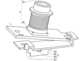
図3及び図4に示すように、ホルダー3は、本体3aと、突出板3bと、嵌合部である凸部3cと、ねじ穴3dとを有する。本体3aは、基板1の配線がショートしないように、基板1の一部から離間されている。突出板3bは、本体3aから撮像部2と逆側に突出する。図4に示す凸部3cは、突出板3bから突出板3bの面外方向に突出する。ねじ穴3dは、突出板3bの中央部分に設けられる。
ホルダー3に固定されるシャーシ4は、複数のシャーシ4から選択的に使用される。図5は、複数のシャーシ4の構成を示す斜視図である。各シャーシ4は、車両の室内に取り付け可能となっている。本実施の形態1では、各シャーシ4は、図1に示す固定穴4eがねじ止めされることによって、車両の室内に取り付け可能となっている。ただし、各シャーシ4の車両の室内への取り付け構造は、これに限ったものではない。
各シャーシ4は、本体4aと、突出板4bと、被嵌合部である穴4cと、ねじ穴4dとを有する。突出板4bは、本体4aから突出する。穴4cは、突出板4bに設けられる。なお、穴4cは、貫通穴であってもよいし、非貫通穴であってもよいし、被嵌合部は、穴ではなく切り欠きであってもよい。ねじ穴4dは、突出板4bの中央部分に設けられる。
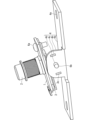
図4のホルダー3の突出板3bのねじ穴3dと、図5の一のシャーシ4の突出板4bのねじ穴4dとに、図1のねじ6bが通される。このため、ホルダー3の凸部3cを一のシャーシ4の穴4cに嵌合しなければ、ホルダー3と一のシャーシ4とは、ねじ6bを回転軸として回転可能となっている。一方、図6に示すように、ホルダー3の凸部3cを一のシャーシ4の穴4cに嵌合することによって、ホルダー3と一のシャーシ4の回転軸を中心とする回転は規制され、ホルダー3と一のシャーシ4との位置関係は固定される。
図4及び図5に示すように、ホルダー3の凸部3cの数と、各シャーシ4の穴4cの数とは同じである。本実施の形態1では、ホルダー3の凸部3cの数は2つであり、各シャーシ4の穴4cの数は2つであるが、これらの数は2つに限ったものではない。また図5に示すように、複数のシャーシ4において、回転軸(つまりねじ穴4d)の周方向における穴4cの位置は互いに異なる。
<実施の形態1のまとめ>
本実施の形態1に係る撮像機器10では、ホルダー3の凸部3cの数と、各シャーシ4の穴4cの数とは同じである。したがって、ユーザは、ホルダー3の凸部3cを嵌合すべき、各シャーシ4の穴4cを容易に理解することができるので、穴4cへの凸部3cの嵌合を容易に行うことができる。
本実施の形態1に係る撮像機器10では、ホルダー3の凸部3cの数と、各シャーシ4の穴4cの数とは同じである。したがって、ユーザは、ホルダー3の凸部3cを嵌合すべき、各シャーシ4の穴4cを容易に理解することができるので、穴4cへの凸部3cの嵌合を容易に行うことができる。
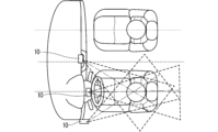
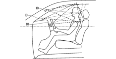
また本実施の形態1に係る撮像機器10の製造方法では、図5のように複数のシャーシ4において、回転軸の周方向における穴4cの位置は互いに異なり、図6のようにホルダー3の凸部3cが、いずれかのシャーシ4の穴4cに嵌合される。このような構成によれば、ホルダー3に固定されるシャーシ4を変更することによって、固定部分においてホルダー3とシャーシ4とがなす角度を変更することができる。これにより図7及び図8に示すように、ホルダー3に固定されるシャーシ4を適切に選択することで、シャーシ4以外の部分を変更しなくても、撮像部2の撮像方向を車両の運転者などの乗員に向けることができる。これにより、撮像機器10の低コスト化が期待できる。また、撮像機器10を適用するDMS(Driver Monitoring System)において、乗員から適切な画像を撮像することができる。
<変形例>
以上の説明では、図5に示したように、複数のシャーシ4のそれぞれにおいて、本体4aと突出板4bとがなす角度は概ね垂直であったが、これに限ったものではない。例えば、複数のシャーシ4において、本体4aと突出板4bとがなす角度が互いに異なってもよい。このような構成によれば、ホルダー3に固定されるシャーシ4を適切に選択することで、上記回転軸と異なる回転軸に沿った、ホルダー3とシャーシ4とがなす角度を変更することができる。
以上の説明では、図5に示したように、複数のシャーシ4のそれぞれにおいて、本体4aと突出板4bとがなす角度は概ね垂直であったが、これに限ったものではない。例えば、複数のシャーシ4において、本体4aと突出板4bとがなす角度が互いに異なってもよい。このような構成によれば、ホルダー3に固定されるシャーシ4を適切に選択することで、上記回転軸と異なる回転軸に沿った、ホルダー3とシャーシ4とがなす角度を変更することができる。
なお、実施の形態の内容を適宜、変形、省略することが可能である。
上記した説明は、すべての局面において、例示であって、限定的なものではない。例示されていない無数の変形例が、想定され得るものと解される。
1 基板、2 撮像部、2a レンズ、2b イメージセンサー、3 ホルダー、3c 凸部、4 シャーシ、4c 穴、5 筐体、10 撮像機器。
Claims (4)
- 車両の室内を撮像する撮像部と、
前記撮像部と基板を介して接続され、嵌合部を有するホルダーと、
前記車両の前記室内に取り付け可能であり、被嵌合部を有するシャーシと
を備え、
前記嵌合部を前記被嵌合部に嵌合することによって、前記ホルダー及び前記シャーシの回転軸を中心とする回転が規制され、
前記嵌合部の数と、前記被嵌合部の数とが同じである、撮像機器。 - 請求項1に記載の撮像機器であって、
前記撮像部は、
レンズと、
前記レンズからの光に基づいて画像を生成するイメージセンサーと
を含み、
前記基板と、前記撮像部と、前記ホルダーと、前記シャーシの一部とを収容する収容部をさらに備える、撮像機器。 - 請求項1または請求項2に記載の撮像機器であって、
前記嵌合部は凸部であり、
前記被嵌合部は穴または切り欠きである、撮像機器。 - 車両の室内を撮像する撮像部と基板を介して接続され、嵌合部を有するホルダーと、前記車両の前記室内に取り付け可能であり、被嵌合部を有する複数のシャーシとを準備し、
前記ホルダーの前記嵌合部を一の前記シャーシの前記被嵌合部に嵌合することによって、前記ホルダーと前記一のシャーシの回転軸を中心とする回転を規制し、
前記嵌合部の数と、前記複数のシャーシのそれぞれの前記被嵌合部の数とが同じであり、
前記複数のシャーシにおいて、前記回転軸の周方向における前記被嵌合部の位置が互いに異なる、撮像機器の製造方法。
Priority Applications (2)
| Application Number | Priority Date | Filing Date | Title |
|---|---|---|---|
| JP2024520138A JP7630064B2 (ja) | 2022-05-11 | 2022-05-11 | 撮像機器 |
| PCT/JP2022/019921 WO2023218552A1 (ja) | 2022-05-11 | 2022-05-11 | 撮像機器及び撮像機器の製造方法 |
Applications Claiming Priority (1)
| Application Number | Priority Date | Filing Date | Title |
|---|---|---|---|
| PCT/JP2022/019921 WO2023218552A1 (ja) | 2022-05-11 | 2022-05-11 | 撮像機器及び撮像機器の製造方法 |
Publications (1)
| Publication Number | Publication Date |
|---|---|
| WO2023218552A1 true WO2023218552A1 (ja) | 2023-11-16 |
Family
ID=88730001
Family Applications (1)
| Application Number | Title | Priority Date | Filing Date |
|---|---|---|---|
| PCT/JP2022/019921 Ceased WO2023218552A1 (ja) | 2022-05-11 | 2022-05-11 | 撮像機器及び撮像機器の製造方法 |
Country Status (2)
| Country | Link |
|---|---|
| JP (1) | JP7630064B2 (ja) |
| WO (1) | WO2023218552A1 (ja) |
Citations (4)
| Publication number | Priority date | Publication date | Assignee | Title |
|---|---|---|---|---|
| JP2001088623A (ja) * | 1999-09-22 | 2001-04-03 | Fuji Heavy Ind Ltd | 車載カメラの取付構造 |
| JP2009280195A (ja) * | 2008-04-25 | 2009-12-03 | Fuji Heavy Ind Ltd | ステレオカメラユニット |
| CN109151282A (zh) * | 2018-09-26 | 2019-01-04 | 上海航盛实业有限公司 | 一种adas单目摄像头及车载电子安全系统 |
| CN112009391A (zh) * | 2020-09-09 | 2020-12-01 | 上海商汤临港智能科技有限公司 | 车载摄像装置、安装方法、车辆及视觉处理系统及方法 |
Family Cites Families (1)
| Publication number | Priority date | Publication date | Assignee | Title |
|---|---|---|---|---|
| JP2012111390A (ja) * | 2010-11-25 | 2012-06-14 | Suzuki Motor Corp | バックドアハンドル |
-
2022
- 2022-05-11 WO PCT/JP2022/019921 patent/WO2023218552A1/ja not_active Ceased
- 2022-05-11 JP JP2024520138A patent/JP7630064B2/ja active Active
Patent Citations (4)
| Publication number | Priority date | Publication date | Assignee | Title |
|---|---|---|---|---|
| JP2001088623A (ja) * | 1999-09-22 | 2001-04-03 | Fuji Heavy Ind Ltd | 車載カメラの取付構造 |
| JP2009280195A (ja) * | 2008-04-25 | 2009-12-03 | Fuji Heavy Ind Ltd | ステレオカメラユニット |
| CN109151282A (zh) * | 2018-09-26 | 2019-01-04 | 上海航盛实业有限公司 | 一种adas单目摄像头及车载电子安全系统 |
| CN112009391A (zh) * | 2020-09-09 | 2020-12-01 | 上海商汤临港智能科技有限公司 | 车载摄像装置、安装方法、车辆及视觉处理系统及方法 |
Also Published As
| Publication number | Publication date |
|---|---|
| JPWO2023218552A1 (ja) | 2023-11-16 |
| JP7630064B2 (ja) | 2025-02-17 |
Similar Documents
| Publication | Publication Date | Title |
|---|---|---|
| JP6827341B2 (ja) | 情報処理装置、カメラ及びカメラ装置 | |
| CN105163006B (zh) | 汽车成像系统及安装成像系统的方法 | |
| JP2006091177A (ja) | ステレオカメラ、およびステレオカメラ用ステー | |
| JP3234888U (ja) | 撮像装置 | |
| JP6060056B2 (ja) | 撮像装置及び撮像装置を用いたステレオカメラ | |
| KR20200143874A (ko) | 모터 제어 장치 | |
| US20030227699A1 (en) | Mirror device for a vehicle | |
| KR20190029242A (ko) | 전자 장치의 영상촬영 보조 액세서리 | |
| JP2026040671A (ja) | 回転装置 | |
| JP6459961B2 (ja) | 受光装置 | |
| JP3766618B2 (ja) | 固体撮像素子の取付構造 | |
| JP6661414B2 (ja) | 電動モータ制御装置 | |
| WO2023218552A1 (ja) | 撮像機器及び撮像機器の製造方法 | |
| JP5133550B2 (ja) | 手振補正機能付カメラにおけるジャイロセンサ取付構造 | |
| JP4654862B2 (ja) | 撮像素子のあおり調整装置およびそれを用いた撮影装置 | |
| JP2001094842A (ja) | 車載カメラにおける室内映り込み防止方法 | |
| JP7162076B2 (ja) | 走行デバイス | |
| JP2009265131A (ja) | レンズ鏡筒固定装置および、それを備えた撮像装置 | |
| JP2012084804A (ja) | コネクタ押さえ部材、および電子機器 | |
| WO2015083617A1 (ja) | 操作ユニット | |
| WO2023145129A1 (ja) | 撮像装置 | |
| JP4365714B2 (ja) | 車載用電子機器 | |
| KR102316419B1 (ko) | 회전 결합 구조의 감시 카메라 모듈 | |
| JP6205495B2 (ja) | 接続ユニット用に改善したベアリングを備えた電子装置、自動車用カメラシステム、および自動車 | |
| JP4701107B2 (ja) | 電動ステアリングロック装置 |
Legal Events
| Date | Code | Title | Description |
|---|---|---|---|
| 121 | Ep: the epo has been informed by wipo that ep was designated in this application |
Ref document number: 22941633 Country of ref document: EP Kind code of ref document: A1 |
|
| ENP | Entry into the national phase |
Ref document number: 2024520138 Country of ref document: JP Kind code of ref document: A |
|
| NENP | Non-entry into the national phase |
Ref country code: DE |
|
| 122 | Ep: pct application non-entry in european phase |
Ref document number: 22941633 Country of ref document: EP Kind code of ref document: A1 |