WO2023218536A1 - ロボット制御装置、ロボットシステム、及び教示装置 - Google Patents
ロボット制御装置、ロボットシステム、及び教示装置 Download PDFInfo
- Publication number
- WO2023218536A1 WO2023218536A1 PCT/JP2022/019846 JP2022019846W WO2023218536A1 WO 2023218536 A1 WO2023218536 A1 WO 2023218536A1 JP 2022019846 W JP2022019846 W JP 2022019846W WO 2023218536 A1 WO2023218536 A1 WO 2023218536A1
- Authority
- WO
- WIPO (PCT)
- Prior art keywords
- robot
- teaching
- teaching point
- detector
- contact
- Prior art date
- Legal status (The legal status is an assumption and is not a legal conclusion. Google has not performed a legal analysis and makes no representation as to the accuracy of the status listed.)
- Ceased
Links
Images




Classifications
-
- G—PHYSICS
- G05—CONTROLLING; REGULATING
- G05B—CONTROL OR REGULATING SYSTEMS IN GENERAL; FUNCTIONAL ELEMENTS OF SUCH SYSTEMS; MONITORING OR TESTING ARRANGEMENTS FOR SUCH SYSTEMS OR ELEMENTS
- G05B19/00—Program-control systems
- G05B19/02—Program-control systems electric
- G05B19/42—Recording and playback systems, i.e. in which the program is recorded from a cycle of operations, e.g. the cycle of operations being manually controlled, after which this record is played back on the same machine
- G05B19/423—Teaching successive positions by walk-through, i.e. the tool head or end effector being grasped and guided directly, with or without servo-assistance, to follow a path
-
- B—PERFORMING OPERATIONS; TRANSPORTING
- B25—HAND TOOLS; PORTABLE POWER-DRIVEN TOOLS; MANIPULATORS
- B25J—MANIPULATORS; CHAMBERS PROVIDED WITH MANIPULATION DEVICES
- B25J9/00—Program-controlled manipulators
- B25J9/0081—Program-controlled manipulators with leader teach-in means
-
- B—PERFORMING OPERATIONS; TRANSPORTING
- B25—HAND TOOLS; PORTABLE POWER-DRIVEN TOOLS; MANIPULATORS
- B25J—MANIPULATORS; CHAMBERS PROVIDED WITH MANIPULATION DEVICES
- B25J13/00—Controls for manipulators
- B25J13/08—Controls for manipulators by means of sensing devices, e.g. viewing or touching devices
- B25J13/081—Touching devices, e.g. pressure-sensitive
- B25J13/084—Tactile sensors
-
- B—PERFORMING OPERATIONS; TRANSPORTING
- B25—HAND TOOLS; PORTABLE POWER-DRIVEN TOOLS; MANIPULATORS
- B25J—MANIPULATORS; CHAMBERS PROVIDED WITH MANIPULATION DEVICES
- B25J9/00—Program-controlled manipulators
- B25J9/16—Program controls
- B25J9/1628—Program controls characterised by the control loop
- B25J9/1633—Program controls characterised by the control loop compliant, force, torque control, e.g. combined with position control
-
- B—PERFORMING OPERATIONS; TRANSPORTING
- B25—HAND TOOLS; PORTABLE POWER-DRIVEN TOOLS; MANIPULATORS
- B25J—MANIPULATORS; CHAMBERS PROVIDED WITH MANIPULATION DEVICES
- B25J9/00—Program-controlled manipulators
- B25J9/16—Program controls
- B25J9/1656—Program controls characterised by programming, planning systems for manipulators
-
- B—PERFORMING OPERATIONS; TRANSPORTING
- B25—HAND TOOLS; PORTABLE POWER-DRIVEN TOOLS; MANIPULATORS
- B25J—MANIPULATORS; CHAMBERS PROVIDED WITH MANIPULATION DEVICES
- B25J9/00—Program-controlled manipulators
- B25J9/16—Program controls
- B25J9/1656—Program controls characterised by programming, planning systems for manipulators
- B25J9/1664—Program controls characterised by programming, planning systems for manipulators characterised by motion, path, trajectory planning
-
- G—PHYSICS
- G05—CONTROLLING; REGULATING
- G05B—CONTROL OR REGULATING SYSTEMS IN GENERAL; FUNCTIONAL ELEMENTS OF SUCH SYSTEMS; MONITORING OR TESTING ARRANGEMENTS FOR SUCH SYSTEMS OR ELEMENTS
- G05B2219/00—Program-control systems
- G05B2219/30—Nc systems
- G05B2219/36—Nc in input of data, input key till input tape
- G05B2219/36401—Record play back, teach position and record it then play back
Definitions
- the present invention relates to a robot control device, a robot system, and a teaching device.
- Patent Document 1 states, ⁇ When performing a lead-through operation, the lead-through switch 44 is pressed and contact force monitoring is disabled. It is possible to prevent the robot 10 from unintentionally stopping due to the applied operating force" (paragraph 0037).
- Patent Document 2 also relates to a robot control device and states, ⁇
- the control unit stores the position and posture of the robot arm at the initial stage when the instructor starts direct teaching by, for example, grasping the robot arm, as an initial reference state.
- the control unit calculates a force control signal according to the position information from the position detection unit and the speed information from the speed detection unit, transmits it to the drive unit, and drives the robot arm. Controls the force or torque of the actuator of the actuator. If the actuator is a linear system, the force is controlled, and if the actuator is a rotary system, the torque is controlled.
- the control unit stores the position and orientation as trajectory teaching values" (Paragraph 0017).
- Direct teaching involves creating a robot program by memorizing the robot's trajectory at predetermined time intervals while the operator is operating the robot, or by having the operator stop the robot at key points and memorize its position. There is a method to create a robot program.
- the method of storing the locus of the robot's movement at predetermined time intervals is suitable for teaching the movement of the robot's tool tip as it moves through the air without touching anything.
- a reaction force is applied to the robot when the robot comes into contact with the workpiece.
- the force sensor or torque sensor mounted on the robot also detects the reaction force, so the robot tends to bounce away from the workpiece the moment it comes into contact with the workpiece. Since the movements of such robots are different from human intuition, it is difficult to teach them.
- One aspect of the present disclosure is a robot control device for controlling a robot, wherein contact between the robot and an object is detected based on an output of a first detector mounted on the robot and capable of detecting contact.
- This robot control device includes a teaching point setting section that sets the position of the robot when detected as a teaching point of a robot program.
- Another aspect of the present disclosure provides a robot equipped with a first detector capable of detecting contact, and a robot that detects contact between the robot and an object based on an output of the first detector.
- This robot system includes a teaching point setting unit that sets a position as a teaching point of a robot program.
- Yet another aspect of the present disclosure is a teaching device for teaching a robot, the robot being able to contact an object based on the output of a first detector mounted on the robot and capable of detecting contact.
- This teaching device includes a teaching point setting section that sets the position of the robot when the robot is detected as the teaching point of the robot program.
- the operator can easily teach a trajectory including a point of contact with the workpiece, such as a trajectory tracing the ridgeline or surface of the workpiece, by direct teaching.
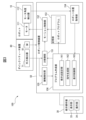
- FIG. 1 is an equipment configuration diagram of a robot system according to a first embodiment. It is a diagram showing an example of the hardware configuration of a robot control device and a teaching pendant.
- FIG. 2 is a functional block diagram of each device configuring the robot system according to the first embodiment.
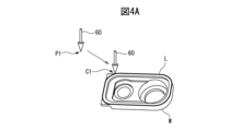
- FIG. 6 is a diagram illustrating an operation of teaching the ridgeline of a workpiece by direct teaching.
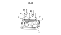
- FIG. 6 is a diagram illustrating an operation of teaching the ridgeline of a workpiece by direct teaching. It is a flowchart showing the procedure of direct teaching. It is a figure which shows the example of a program creation screen. It is a figure showing the setting screen of a direct teaching icon.
- FIG. 7 is a diagram illustrating an example of a state in which direct operation icons are expanded and displayed.
- FIG. 3 is an equipment configuration diagram of a robot system according to a second embodiment.
- FIG. 2 is a functional block diagram of a robot system according to a second embodiment.
- FIG. 3 is a functional block diagram
- the robot system according to each embodiment is a system that allows an operator to directly operate a robot and perform direct teaching.
- FIG. 1 is an equipment configuration diagram of a robot system 100 according to a first embodiment.
- the robot system 100 includes a robot 10, a robot control device 50 that controls the robot 10, and a teaching operation panel 30 used to perform various settings and operations related to teaching.
- the robot 10 includes a base 11 fixed to an installation floor and a plurality of links mounted on the base 11. These multiple links constitute a rotating torso 12, a lower arm 13, an upper arm 14, and a wrist 15 of the robot.
- the robot 10 can perform desired tasks with an end effector attached to the wrist flange 16.
- the end effector is an external device that can be replaced depending on the application, and is, for example, a hand, a welding gun, a tool, or the like.
- FIG. 1 shows an example in which a deburring tool 60 is used as an example of an end effector.
- a direct teach device 80 is further disposed on the wrist flange 16 of the robot 10, which is used when the operator performs direct teach.
- the direct teach device 80 includes an operation handle 82 and an operation switch 81 (see FIG. 3) that includes a switch for enabling and disabling the direct teach operation and other functional switches.
- the direct teach device 80 is attached to the wrist flange 16 of the robot 10 via an external force detector 71.
- a deburring tool 60 is further attached to the wrist flange 16 of the robot 10 on the distal side of the direct teach device 80 .
- a signal from the operation switch 81 is provided to the robot control device 50 and used for control during the direct teach operation.
- the external force detector 71 can detect external force applied to the robot 10.
- a force sensor or a load cell can be used as the external force detector 71.
- a force sensor is used as the external force detector 71.
- the force sensor is, for example, a six-axis force sensor that detects forces in three axial directions and moments around the three axes.
- the detected value of the force sensor is input to the robot control device 50.
- the external force applied to the robot 10 may be detected by a torque sensor placed at each joint axis of the robot 10. Alternatively, the force applied to the robot may be determined from the current value flowing through the motor of each axis of the robot.
- the magnitude and direction of the operating force when the operator OP operates the operating handle 82 of the direct teach device 80 are detected by the external force detector 71, and the robot 10 (arm tip part) can be moved.
- the robot control device 50 has a function of controlling the robot 10 according to a robot program, a function of controlling the robot 10 according to commands from a teaching operation panel, and a function of controlling the robot 10 by the operator OP using the direct teach device 80. It has functions such as controlling the operation of direct teaching.
- An operator can create a robot program for performing work on a work W as illustrated in FIG. 1 by direct teaching.
- the robot control device 50 allows an operator to easily teach a trajectory including contact points with a workpiece by direct teaching, such as a trajectory tracing the ridgeline or surface of the workpiece.
- FIG. 2 shows an example of the hardware configuration of the robot control device 50 and the teaching pendant 30.
- the robot control device 50 is a general robot controller in which a processor 51 is connected to a memory 52 (ROM, RAM, non-volatile memory, etc.), various input/output interfaces 53, an operation section 54 including various operation switches, etc. via a bus. It may have a configuration as a computer.
- the teaching pendant 30 provides a processor 31 with a memory 32 (ROM, RAM, non-volatile memory, etc.), a display section 33, an operation section 34 comprised of input devices such as a keyboard (or software keys), and various input/outputs. It may have a general computer configuration in which the interface 35 and the like are connected via a bus.
- FIG. 3 is a functional block diagram of each device that makes up the robot system 100.
- a motor 111 that drives the joint axis and a motor angle detector 112 that detects the position (angular position) of the motor are arranged at each joint of the robot 10.
- a motor 111 and a motor angle detector 112 provided on one joint axis are representatively illustrated.
- the robot control device includes a force control section 151, a motion control section 152, a storage section 153, a robot position acquisition section 154, a contact detection section 155, and a program creation section 156.
- the force control unit 151 has a function of generating a command to move the robot 10 according to the external force detected by the external force detector 71.
- the force control unit 151 generates a motion command so that the robot 10 moves in the direction of the external force detected by the external force detector 71 (the direction of the force that the operator OP applies to the robot 10).
- the motion control unit 152 generates commands for each joint axis of the robot 10 by kinematic calculation in accordance with commands from the force control unit 151, and executes servo control for the motors of each joint axis. Thereby, the robot 10 can operate according to the command from the force control section 151. Thereby, in direct teaching, the function of moving the robot 10 (deburring tool 60) in the direction of the force that the operator OP applies to the operating handle 82 of the direct teaching device 80 is realized.
- the storage unit 153 stores the robot program created by the program creation unit 156, various information necessary for programming, and the like.
- the external force detected by the external force detector 71 is further input to the contact detection section 155, and contact between the robot 10 and the object is detected.
- the contact detection unit 155 includes, for example, (1) When the magnitude of the force or moment detected by the external force detector 71 exceeds a predetermined threshold, or (2) When the force or moment detected by the external force detector 71 is reversed, Alternatively, it may be detected that there is contact between the robot 10 and the object.
- the contact detection section 155 sends a signal to the program creation section 156 to notify it.
- the threshold value for the contact detection unit 155 to determine whether or not there has been contact is, for example, (1) A method in which the maximum force is recorded when the robot 10 is operating by direct teaching without contacting anything, and a value larger than the maximum force by a predetermined margin is determined as a threshold value, or (2) A method that allows the user to set a threshold; is possible.
- the robot position acquisition unit 154 determines the position and orientation of the robot 10 based on the output of the motor angle detector 112 arranged at each joint axis.
- the robot position acquisition unit 154 provides the acquired information on the position and orientation of the robot 10 to the program creation unit 156.
- the program creation unit 156 has various functions for creating robot programs.
- the functions of the program creation unit 156 include a function of creating a robot program by direct teaching.
- the program creation section 156 includes a teaching point setting section 161, a command generation section 162, and a display control section 163.
- the teaching point setting unit 161 provides a function of setting teaching points in direct teaching.
- the teaching point setting section 161 has a function of setting the position and orientation of the robot 10 when the contact detection section 155 detects contact between the robot 10 and an object as a teaching point.
- the command generation unit 162 has a function of generating operation commands for the robot 10 based on the teaching points set by the teaching point setting unit 161.
- the display control unit 163 has a function of generating various UI (user interface) screens for creating programs, a function of supporting various operation inputs via the UI screen, and the like.
- various UI screens for programming are displayed on the display section 33 of the teaching pendant 30, and operations on the UI screens are performed via the operating section 34.
- the robot program in this case is a program for moving the deburring tool 60 so as to trace the end surface (edge line L) of the workpiece W with the deburring tool 60 .
- the robot control device 50 (program creation unit 156) according to the present embodiment solves the above-mentioned problems when teaching the ridgeline of a workpiece by direct teaching. This problem can be solved by using a configuration that allows the position and orientation of the robot when it comes into contact with the robot to be acquired as a teaching point.
- FIGS. 4A and 4B are diagrams illustrating the operation of teaching the trajectory of the ridge line L of the workpiece W by direct teaching according to the present embodiment. Note that in FIGS. 4A and 4B, only the workpiece W and the deburring tool 60 are illustrated for convenience of explanation.
- the operator OP performs a predetermined operation to start direct teaching.
- the operation for starting direct teaching may be, for example, by operating the operation switch 81 of the direct teaching device 80 or by operating the UI screen displayed on the teaching operation panel 30.
- the operator OP first records the teaching starting point P1 while operating the robot 10 using the direct teaching device 80.
- the operator OP causes the robot 10 (deburring tool 60) to approach the workpiece W from the teaching starting point P1.
- the teaching point setting unit 161 acquires the position of the moving robot 10 from the teaching start point P1 to the first contact point C1 with the workpiece W at predetermined time intervals and automatically records it as a teaching point. You may do so.
- the teaching point setting unit 161 automatically records the contact point C1 where the deburring tool 60 first contacts the workpiece W as a teaching point.
- the robot 10 may move away from the workpiece W, but in this case, the position D1 where the deburring tool 60 is separated from the workpiece W is not recorded as a teaching point.
- the operator OP brings the deburring tool 60 close to the workpiece W again and brings it into contact with the workpiece W.
- This second contact point C2 is also automatically recorded as a teaching point.
- the deburring tool 60 leaves the workpiece W again, but the position D2 at this time is not recorded.
- the contact point C3 at which the operator OP next brings the deburring tool 60 into contact with the workpiece W is automatically recorded as a teaching point.
- the operator OP continues such operations along the entire ridge line L, and sets teaching points along the entire ridge line L.
- the positions where the deburring tool and the workpiece W come into contact are automatically recorded as teaching points. That is, a plurality of teaching points can be set at positions along the ridge line L. Since the position when the deburring tool 60 contacts the workpiece W is automatically recorded, the operator OP can easily create a trajectory that follows the ridgeline L of the workpiece W.
- the operator OP should not move the robot to the workpiece at points where the direction of the trajectory changes significantly (for example, at corners) or at points where the robot posture (tool posture) changes significantly. It is desirable to take care to make contact and record it as a teaching point.
- the force control unit 151 controls the robot 10 (control portion) to move in the direction of the external force detected by the external force detector 71, that is, the force applied to the robot 10 by the operator OP during direct teaching.
- force control control for moving the robot in the direction of the applied force at a speed proportional to the magnitude of the force, impedance control, or damping control may be adopted.
- impedance control is a method of controlling the operation of a robot (control portion) using an equation of motion representing mechanical impedance characteristics defined by a virtual coefficient of inertia, viscosity, and elasticity.
- Damping control is a method of determining mechanical impedance characteristics based on the viscosity coefficient.
- the force control unit 151 When performing direct teaching according to the present embodiment, it is desirable that the force control unit 151 performs force control such that when the robot 10 comes into contact with the object, the movement of moving away from the object or jumping up is reduced. Damping control is a method that can suppress or reduce behavior in which the robot (control portion) moves away from the object or jumps up when the robot 10 comes into contact with the object.
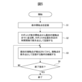
- FIG. 5 is a flowchart showing the direct teaching procedure described above with reference to FIGS. 4A and 4B.
- This direct teach process is activated in response to a predetermined operation that instructs the start of direct teach.
- the program creation unit 156 (teaching point setting unit 161) records the position of the robot when direct teaching is started as a teaching start point P1 in response to the operation of the operating handle 82 by the operator OP (step S1).
- the teaching point setting unit 161 adjusts the position of the robot 10 to the teaching point at predetermined time intervals while the robot 10 is operated by the operator OP and the robot 10 moves from the teaching start point P1 to the first contact point. (Step S2).
- the teaching point setting unit 161 sets the position (contact point) of the robot 10 when the robot 10 first contacts the workpiece W (when the first contact is detected by the contact detection unit 155) as the teaching point.
- the operation of recording the position of the robot 10 (contact point) when contact between the robot 10 and the workpiece W is detected as a teaching point is continued (step S3).
- the teaching point setting unit 161 records only the contact point, and does not record the position when the robot 10 leaves the workpiece W.
- the teaching point setting unit 161 continues the operation of recording the contact point (step S3) until an instruction to end direct teaching is given (step S4: NO).
- the instruction to end direct teaching may be given by, for example, operating the operation switch 81 of the direct teaching device 80.
- the termination instruction is given (step S4: YES), this process is terminated.
- the teaching point setting unit 161 may apply either of the following rules (r1) and (r2).
- r1 After recording one teaching point (contact point), the next teaching point (contact point) is not captured until a predetermined time has elapsed.
- r2 After recording one teaching point (contact point), the next teaching point (contact point) is not captured until the robot (control part) is away from it by a predetermined distance or more.
- the program creation unit 156 can provide a function for programming via the UI screen.
- programming and direct teach operations via the UI screen will be described in the case where the program creation unit 156 has a function of performing icon-based programming.
- the UI screen is displayed on the display screen of the display section 33 of the teaching pendant 30, and can be operated via the operation section 34 (software keys arranged on the display screen, etc.).
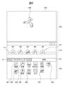
- FIG. 6 is a diagram showing a program creation screen 300 generated by the display control unit 163 of the program creation unit 156.
- the program creation screen 300 includes a program display area 310, an icon display area 320, and an operation status display area 330 that displays the robot's operation trajectory and the like.
- the icon display area 320 is an area for displaying a list of icons that can be used for programming.
- the icon display area 320 includes a linear movement icon 401, each axis movement icon 402, an if statement icon 403, a for loop icon 404, a grip icon 405, a release icon 406, and a direct teaching icon 407. It is.
- the linear movement icon 401 is an icon corresponding to a command to move the robot (predetermined control part) in a straight line.
- Each axis movement icon 402 is an icon corresponding to a command to move the robot (predetermined control part) on each axis.
- the if statement icon 403 is an icon corresponding to a conditional branch instruction of the program.
- the For loop icon 404 is an icon corresponding to a loop conditional command of the program.
- the gripping icon 405 is an icon corresponding to a command to close the hand and grip the workpiece.
- the release icon 406 is an icon corresponding to a command to open the hand and release the workpiece.
- the direct teaching icon 407 is an icon corresponding to a command for performing direct teaching.
- the program display area 310 is an area for creating and displaying a program by arranging icons selected from the icon display area 320.
- the robot model 10M can be caused to perform a simulated operation according to the teaching content.
- the operator can perform programming by selecting desired icons from the icon display area 320 and arranging them in order along the timeline 311 of the program display area 310.
- a robot program 501 including a linear movement icon 401, each axis movement icon 402, a direct teaching icon 407, each axis movement icon 402, and a linear movement icon 401 is created.
- the operator selects the programming tab 371.
- a settings screen for that icon can be opened and detailed settings can be made.
- the operator OP can open the setting screen for the direct teaching icon 407 by performing a predetermined operation on the program creation screen 300 in FIG.
- a predetermined operation an operation of selecting the direct teaching icon 407 in the program display area 310 and selecting the details tab 372 may be used.
- FIG. 7 shows a state in which the setting screen 321 of the direct teaching icon 407 is displayed by selecting the direct teaching icon 407 in the program display area 310 of FIG. 6 and selecting the details tab 372.
- the setting screen 321 includes a speed setting field 451 for teaching the movement speed of the robot (predetermined control part). The operator can teach the moving speed of the robot 10 by inputting a numerical value into the speed setting field 451 or by operating a button next to the speed setting field 451.
- the setting screen 321 has a status display column 452 that displays the status of direct teaching.
- the status display column 452 displays the status of direct teaching. In the example of FIG. 7, since direct teaching has not yet been performed, the state display field 452 displays "trajectory not taught".
- the setting screen 321 has a teaching start button 455 and a teaching stop button 456 for specifying the start and stop of direct teaching, respectively.
- the operator can start direct teaching according to this embodiment by pressing the teaching start button 455. Further, the operator can stop direct teaching by pressing the teaching stop button 456.
- the setting screen 321 is provided with a teaching interval specification field 453 for specifying the teaching interval.
- the time interval for automatically recording the trajectory of the robot from the teaching start point to the first contact point, as described in step S2 of FIG. 4, is specified.
- the setting screen 321 includes an operation type specification field 454 for specifying the operation type of the robot.
- the motion type specification column 454 linear motion, each axis motion, etc. can be specified.
- FIG. 7 shows an example in which each axis motion (“kakujiku”) is specified as the robot motion.
- the command generation unit 162 generates each axis movement as an operation command.
- the operator can perform direct teaching in the manner described above with reference to FIGS. 4A to 4B. It is assumed that parameters are also input via the setting screen 321 and that direct teaching is also executed.
- the command generation unit 162 generates a program according to the acquired teaching points and taught parameters.
- the operator performs a predetermined operation on the direct teach icon 407 (for example, clicks the direct teach icon 407 on the program display area 310 of the program creation screen 300 in FIG. 6 or on the screen on which the setting screen 321 in FIG. 7 is displayed). By performing a double-click operation), the direct teaching icon 407 can be expanded to display its contents.
- FIG. 8 shows an example of a state in which the direct teaching icon 407 is expanded and displayed.
- the direct teaching icon 407 is expanded and displayed in a wide state, and the movement command to each teaching point by direct teaching (here, each axis operation icon 402) is expanded and displayed.
- the operator OP can confirm the content of the program by direct teaching.
- the expanded display state shown in FIG. 8 by selecting each axis movement icon 402 to open its setting screen, it is also possible to confirm and adjust the teaching content.
- the operator can easily teach a trajectory including contact points with the workpiece by direct teaching, such as a trajectory tracing the ridgeline or surface of the workpiece. become able to.
- the entire functions provided by the robot control device 50 and the teaching pendant 30 can also be positioned as a teaching device.
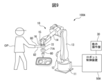
- FIG. 9 is an equipment configuration diagram of a robot system 100A according to the second embodiment.
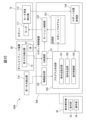
- FIG. 10 is a functional block diagram of the robot system 100A. Note that in FIGS. 9 and 10, the same components as those of the robot system 100 according to the first embodiment are denoted by the same reference numerals.
- the first embodiment was a configuration example in which force control and contact detection are performed from the output of the external force detector 71.
- an external force detector for detecting contact is used separately from the external force detector used for force control.
- the detector used to detect contact is referred to as a first external force detector (denoted with reference numeral 71A in FIGS. 9 and 10)
- the detector used for force control is referred to as a second external force detector (denoted with reference numeral 71A in FIGS. 9 and 10). and 72 in FIG. 10).
- a first external force detector denoted with reference numeral 71A in FIGS. 9 and 10
- a second external force detector denoted with reference numeral 71A in FIGS. 9 and 10
- 72 in FIG. 10
- the robot system 100A includes a second external force detector 72 disposed at a position corresponding to the external force detector 71 in the first embodiment, and a tip of the robot 10 that is lower than the direct teach device 80.
- a first external force detector 71A is provided on the side.
- the tip side of the robot refers to the side closer to the tool tip (that is, the side closer to the workpiece).
- the second external force detector 72 can be configured by the same detector as the external force detector 71 in the first embodiment.
- the output from the first external force detector 71A is input to the contact detection section 155 of the robot control device 50A.
- the contact detection unit 155 detects that there has been contact between the robot and the object when the detected external force exceeds a predetermined threshold.
- the first external force detector 71A is disposed on the robot 10 closer to the tip than the part touched by the operator for direct teaching. With this configuration, the contact force applied to the robot 10 when the deburring tool 60 of the robot 10 comes into contact with the object can be detected with even greater accuracy.
- the program creation unit 156 in the second embodiment can also provide the same functions as in the first embodiment. That is, in the second embodiment as well, the program creation unit 156 allows the operator to easily perform direct teaching of the trajectory including the contact point with the workpiece W, as described with reference to FIGS. 4A and 4B. possible.
- the first external force detector 71A can be configured with a force sensor or a load cell, but a mechanical switch that detects contact with the external environment may also be used as the first external force detector 71A. good.
- the arrangement position of the mechanical switch is set so that the mechanical switch comes into contact with the workpiece when the operator brings the tool into contact with the workpiece in direct teaching.
- the program creation unit 156 can provide a function to perform direct teaching via the UI screens as illustrated in FIGS. 6 to 8.
- the operator can easily teach a trajectory including contact points with the workpiece by direct teaching, such as a trajectory tracing the ridgeline or surface of the workpiece. become.
- the entire function provided by the robot control device 50A and the teaching pendant 30 can also be positioned as a teaching device.
- the robot system 100B according to a third embodiment will be described below.
- the robot system according to the first embodiment and the second embodiment has a configuration example in which the function as the program creation section 156 is provided in the robot control device 50, 50A, but the function as the program creation section 156 is provided on the teaching operation panel.
- a configuration in which the teaching device is provided within a teaching device is also possible.
- the robot system 100B according to the third embodiment is a configuration example in which the function of the program creation section 156 is realized on a teaching pendant (teaching device).
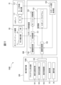
- FIG. 11 shows a functional block diagram of a robot system 100B according to the third embodiment.
- the same reference numerals are used for functional elements equivalent to those in the first embodiment.
- the function of the program creation section 156 which was arranged in the robot control device 50 in the first embodiment, is arranged in the teaching pendant (teaching device) 30B.
- signals indicating contact from the contact detection section 155, information on the robot's position and posture from the robot position acquisition section 154, and other information related to various robot controls are stored in the robot control device 50. It is provided to the program creation section 156B in the teaching pendant 30B via the communication control section 159 and the communication control section 135 in the teaching pendant 30B. The notification signal to the force control unit 151 and the robot program generated by the program creation unit 156B are provided to the robot control device 50B via the communication control unit 135 and the communication control unit 159.
- the program creation unit 156B in the third embodiment can also provide the same functions as the program creation unit 156 in the first embodiment. That is, in the third embodiment as well, the program creation unit 156B allows the operator to easily perform direct teaching of the trajectory including the contact point with the workpiece W, as described with reference to FIGS. 4A and 4B. possible.
- the program creation unit 156B can provide a function of performing direct teaching via the UI screens as illustrated in FIGS. 6 to 8.
- the operator can easily teach a trajectory that includes contact points with the workpiece by direct teaching, such as a trajectory that traces the ridgeline or surface of the workpiece. become.
- the operator can easily teach a trajectory that includes contact points with the workpiece, such as a trajectory that traces the ridgeline or surface of the workpiece, by direct teaching. It becomes like this.
- the distribution of functional blocks in the functional block diagrams shown in FIGS. 3, 10, and 11 is merely an example, and various modifications can be made regarding the arrangement of functions within the robot system.
- the functional block diagram shown in FIG. 11 there may be a configuration in which the function of the command generation section 162 arranged in the program creation section 156B of the teaching pendant 30B is arranged on the robot control device 50B side.
- the teaching point recorded on the teaching pendant 30B side is provided to the robot control device 50B side, and the robot control device 50 side generates a robot program.
- the functional blocks shown in FIGS. 3, 10, and 11 may be realized by a processor of a robot control device or a teaching device executing various software stored in a storage device, or, It may be realized by a configuration mainly based on hardware such as an ASIC (Application Specific Integrated Circuit).
- ASIC Application Specific Integrated Circuit
- the programs that execute various processes such as the direct teach process in the embodiments described above are stored in various computer-readable recording media (for example, ROM, EEPROM, semiconductor memory such as flash memory, magnetic recording medium, CD-ROM, DVD). - Can be recorded on optical discs such as ROM).
Landscapes
- Engineering & Computer Science (AREA)
- Robotics (AREA)
- Mechanical Engineering (AREA)
- Human Computer Interaction (AREA)
- Physics & Mathematics (AREA)
- General Physics & Mathematics (AREA)
- Automation & Control Theory (AREA)
- Numerical Control (AREA)
- Manipulator (AREA)
Abstract
Description
図1は第1実施形態に係るロボットシステム100の機器構成図である。図1に示すように、ロボットシステム100は、ロボット10と、ロボット10を制御するロボット制御装置50と、教示に関する各種設定や操作を行う場合に用いる教示操作盤30とを含む。
(1)外力検出器71により検出された力又はモーメントの大きさが所定の閾値を超えた場合、或いは、
(2)外力検出器71により検出される力又はモーメントが反転した場合、
にロボット10と対象物との接触があったと検知するようにしても良い。接触が検出された場合、接触検知部155は、プログラム作成部156に対して信号を送出して通知する。
(1)ロボット10がどこにも接触しない状態でダイレクトティーチによりロボットを動作させている場合の最大力を記録し、当該最大力よりも所定のマージンだけ大きな値を閾値として決定する手法、或いは、
(2)ユーザが閾値を設定可能とする手法、
が有り得る。
(r1)一つの教示点(接触点)を記録した後、所定の時間を経過するまでは次の教示点(接触点)を取り込まないようにする。
(r2)一つの教示点(接触点)を記録した後、ロボット(制御部位)がそこから所定距離以上離れるまでは次の教示点(接触点)を取り込まないようにする。
上記規則(r1)又は(r2)のいずれかを採用することにより教示点の数が過剰になることを防ぐことができる。
以下、第2実施形態に係るロボットシステム100Aについて説明する。図9は、第2実施形態に係るロボットシステム100Aの機器構成図であり。図10は、ロボットシステム100Aの機能ブロック図である。なお、図9及び図10において第1実施形態に係るロボットシステム100と同一の構成要素には同一の符号を付している。
以下、第3実施形態に係るロボットシステム100Bについて説明する。第1実施形態及び第2実施形態に係るロボットシステムは、プログラム作成部156としての機能をロボット制御装置内50、50Aに備える構成例であったが、プログラム作成部156としての機能を教示操作盤(教示装置)内に備えるような構成も有り得る。第3実施形態に係るロボットシステム100Bは、プログラム作成部156としての機能を教示操作盤(教示装置)上に実現した場合の構成例である。
30、30B 教示操作盤
31 プロセッサ
32 メモリ
33 表示部
34 操作部
35 入出力インタフェース
50、50A ロボット制御装置
51 プロセッサ
52 メモリ
53 入出力インタフェース
54 操作部
60 バリ取りツール
71 外力検出器
71A 第1外力検出器
72 第2外力検出器
80 ダイレクトティーチ装置
81 操作スイッチ
100、100A、100B ロボットシステム
111 モータ
112 モータ角度検出器
135 通信制御部
151 力制御部
152 モーション制御部
153 記憶部
154 ロボット位置取得部
155 接触検知部
156 プログラム作成部
159 通信制御部
161 教示点設定部
162 指令生成部
163 表示制御部
300 プログラム作成画面
310 プログラム表示領域
320 アイコン表示領域
321 設定画面
330 動作状態表示領域
Claims (14)
- ロボットを制御するためのロボット制御装置であって、
前記ロボットに搭載された、接触を検知可能な第1検出器の出力に基づいて該ロボットと対象物との接触が検出されたときの該ロボットの位置をロボットプログラムの教示点として設定する教示点設定部を備える、ロボット制御装置。 - 前記第1検出器は外力を検出する外力検出器であり、
前記第1検出器により検出された外力にしたがって前記ロボットが移動するように制御する力制御部を更に備え、
前記教示点設定部は、前記力制御部の制御により前記ロボットが移動している間に前記ロボットと前記対象物との接触が検出されたときの該ロボットの位置をロボットプログラムの教示点として設定する、請求項1に記載のロボット制御装置。 - 前記ロボットに搭載された、外力を検出するための第2検出器により検出された外力にしたがって前記ロボットが移動するように制御する力制御部を更に備え、
前記教示点設定部は、前記力制御部の制御により前記ロボットが移動している間に前記ロボットと前記対象物との接触が検出されたときの該ロボットの位置をロボットプログラムの教示点として設定する、請求項1に記載のロボット制御装置。 - 前記力制御部は、ダンピング制御による力制御を実行する、請求項2又は3に記載のロボット制御装置。
- 前記教示点設定部は、一つの教示点を設定した後、所定の時間が経過するまでは次の教示点を設定しないように動作する、請求項1から4のいずれか一項に記載のロボット制御装置。
- 前記教示点設定部は、一つの教示点と次の教示点との間の間隔が所定の距離以上となるように動作する、請求項1から4のいずれか一項に記載のロボット制御装置。
- 接触を検知可能な第1検出器を搭載したロボットと、
前記第1検出器の出力に基づいて該ロボットと対象物との接触が検出されたときの該ロボットの位置をロボットプログラムの教示点として設定する教示点設定部と、を備えるロボットシステム。 - 前記第1検出器は外力を検出する外力検出器であり、
前記第1検出器により検出された外力にしたがって前記ロボットが移動するように制御する力制御部を更に備え、
前記教示点設定部は、前記力制御部の制御により前記ロボットが移動している間に前記ロボットと前記対象物との接触が検出されたときの該ロボットの位置をロボットプログラムの教示点として設定する、請求項7に記載のロボットシステム。 - 前記ロボットは外力を検出するための第2検出器を更に搭載し、
前記第2検出器により検出された外力にしたがって前記ロボットが移動するように制御する力制御部を更に備え、
前記教示点設定部は、前記力制御部の制御により前記ロボットが移動している間に前記ロボットと前記対象物との接触が検出されたときの該ロボットの位置をロボットプログラムの教示点として設定する、請求項7に記載のロボットシステム。 - 前記第1検出器は、前記第2検出器よりも前記ロボットの先端側に配置されている、請求項9に記載のロボットシステム。
- 前記力制御部は、ダンピング制御による力制御を実行する、請求項8から10のいずれいか一項に記載のロボットシステム。
- 前記教示点設定部は、一つの教示点を設定した後、所定の時間が経過するまでは次の教示点を設定しないように動作する、請求項7から11のいずれか一項に記載のロボットシステム。
- 前記教示点設定部は、一つの教示点と次の教示点との間の間隔が所定の距離以上となるように動作する、請求項7から11のいずれか一項に記載のロボットシステム。
- ロボットを教示するための教示装置であって、
前記ロボットに搭載された、接触を検知可能な第1検出器の出力に基づいて該ロボットと対象物との接触が検出されたときの該ロボットの位置をロボットプログラムの教示点として設定する教示点設定部を備える、教示装置。
Priority Applications (6)
| Application Number | Priority Date | Filing Date | Title |
|---|---|---|---|
| DE112022006785.3T DE112022006785T5 (de) | 2022-05-10 | 2022-05-10 | Robotersteuervorrichtung, Robotersystem und Einlernvorrichtung |
| PCT/JP2022/019846 WO2023218536A1 (ja) | 2022-05-10 | 2022-05-10 | ロボット制御装置、ロボットシステム、及び教示装置 |
| US18/861,937 US20250289118A1 (en) | 2022-05-10 | 2022-05-10 | Robot control device, robot system, and teaching device |
| JP2024520124A JPWO2023218536A1 (ja) | 2022-05-10 | 2022-05-10 | |
| CN202280095619.8A CN119136954A (zh) | 2022-05-10 | 2022-05-10 | 机器人控制装置、机器人系统以及示教装置 |
| TW112113206A TW202344357A (zh) | 2022-05-10 | 2023-04-10 | 機器人控制裝置、機器人系統及教示裝置 |
Applications Claiming Priority (1)
| Application Number | Priority Date | Filing Date | Title |
|---|---|---|---|
| PCT/JP2022/019846 WO2023218536A1 (ja) | 2022-05-10 | 2022-05-10 | ロボット制御装置、ロボットシステム、及び教示装置 |
Publications (1)
| Publication Number | Publication Date |
|---|---|
| WO2023218536A1 true WO2023218536A1 (ja) | 2023-11-16 |
Family
ID=88730009
Family Applications (1)
| Application Number | Title | Priority Date | Filing Date |
|---|---|---|---|
| PCT/JP2022/019846 Ceased WO2023218536A1 (ja) | 2022-05-10 | 2022-05-10 | ロボット制御装置、ロボットシステム、及び教示装置 |
Country Status (6)
| Country | Link |
|---|---|
| US (1) | US20250289118A1 (ja) |
| JP (1) | JPWO2023218536A1 (ja) |
| CN (1) | CN119136954A (ja) |
| DE (1) | DE112022006785T5 (ja) |
| TW (1) | TW202344357A (ja) |
| WO (1) | WO2023218536A1 (ja) |
Citations (5)
| Publication number | Priority date | Publication date | Assignee | Title |
|---|---|---|---|---|
| JPH03123908A (ja) * | 1989-10-06 | 1991-05-27 | Hitachi Constr Mach Co Ltd | ロボットの位置と姿勢の直接教示装置及び直接教示方法 |
| JPH06110543A (ja) * | 1992-09-30 | 1994-04-22 | Nippon Telegr & Teleph Corp <Ntt> | 直接教示装置 |
| JPH0724758A (ja) * | 1993-07-06 | 1995-01-27 | Fanuc Ltd | 位置決め機構の位置教示方式 |
| JPH07308879A (ja) * | 1994-05-13 | 1995-11-28 | Nippon Telegr & Teleph Corp <Ntt> | ロボットの自動教示法 |
| JP2001038659A (ja) * | 1999-07-26 | 2001-02-13 | Toshiba Mach Co Ltd | 教示点データ測定ツールと、作業用ロボットおよび教示点位置・姿勢データ測定方法 |
Family Cites Families (5)
| Publication number | Priority date | Publication date | Assignee | Title |
|---|---|---|---|---|
| JP2017124470A (ja) * | 2016-01-14 | 2017-07-20 | セイコーエプソン株式会社 | ロボット、及びロボットシステム |
| CN107717981B (zh) * | 2016-08-12 | 2021-01-05 | 财团法人工业技术研究院 | 机械手臂的控制装置及其教导系统与方法 |
| CN107790313B (zh) * | 2016-08-30 | 2021-06-01 | 精工爱普生株式会社 | 控制装置、机器人及机器人系统 |
| JP7483321B2 (ja) * | 2018-02-13 | 2024-05-15 | キヤノン株式会社 | 制御装置、制御方法、ロボットシステム、物品の製造方法、表示装置、プログラム及び記録媒体 |
| JP7481097B2 (ja) * | 2019-08-23 | 2024-05-10 | ファナック株式会社 | ロボット制御装置 |
-
2022
- 2022-05-10 JP JP2024520124A patent/JPWO2023218536A1/ja active Pending
- 2022-05-10 US US18/861,937 patent/US20250289118A1/en active Pending
- 2022-05-10 DE DE112022006785.3T patent/DE112022006785T5/de active Pending
- 2022-05-10 WO PCT/JP2022/019846 patent/WO2023218536A1/ja not_active Ceased
- 2022-05-10 CN CN202280095619.8A patent/CN119136954A/zh active Pending
-
2023
- 2023-04-10 TW TW112113206A patent/TW202344357A/zh unknown
Patent Citations (5)
| Publication number | Priority date | Publication date | Assignee | Title |
|---|---|---|---|---|
| JPH03123908A (ja) * | 1989-10-06 | 1991-05-27 | Hitachi Constr Mach Co Ltd | ロボットの位置と姿勢の直接教示装置及び直接教示方法 |
| JPH06110543A (ja) * | 1992-09-30 | 1994-04-22 | Nippon Telegr & Teleph Corp <Ntt> | 直接教示装置 |
| JPH0724758A (ja) * | 1993-07-06 | 1995-01-27 | Fanuc Ltd | 位置決め機構の位置教示方式 |
| JPH07308879A (ja) * | 1994-05-13 | 1995-11-28 | Nippon Telegr & Teleph Corp <Ntt> | ロボットの自動教示法 |
| JP2001038659A (ja) * | 1999-07-26 | 2001-02-13 | Toshiba Mach Co Ltd | 教示点データ測定ツールと、作業用ロボットおよび教示点位置・姿勢データ測定方法 |
Also Published As
| Publication number | Publication date |
|---|---|
| JPWO2023218536A1 (ja) | 2023-11-16 |
| DE112022006785T5 (de) | 2025-06-18 |
| TW202344357A (zh) | 2023-11-16 |
| US20250289118A1 (en) | 2025-09-18 |
| CN119136954A (zh) | 2024-12-13 |
Similar Documents
| Publication | Publication Date | Title |
|---|---|---|
| JP5545534B2 (ja) | ロボットの教示再生装置、教示再生方法、及び教示データ作成方法 | |
| JP6953778B2 (ja) | 協調ロボット、コントローラ、および方法 | |
| JP7049069B2 (ja) | ロボットシステム及びロボットシステムの制御方法 | |
| JP5338297B2 (ja) | ロボットの制御装置 | |
| JP5176790B2 (ja) | ロボットの教示再生装置および教示再生方法 | |
| US20150217445A1 (en) | Method For Programming An Industrial Robot and Industrial Robot | |
| JP2019136860A (ja) | ロボットの制御装置、制御方法、ロボットシステム、プログラム及び記録媒体 | |
| JP5601949B2 (ja) | ロボット制御システム | |
| JP7483420B2 (ja) | ロボットシステム、制御装置、情報処理装置、制御方法、情報処理方法、物品の製造方法、プログラム、および記録媒体 | |
| WO2023218536A1 (ja) | ロボット制御装置、ロボットシステム、及び教示装置 | |
| US12515316B2 (en) | Operation apparatus, robot system, manufacturing method, control method, and recording medium | |
| US20230264353A1 (en) | Manipulation apparatus, robot system, manipulation apparatus control method, and robot system control method | |
| JP2017202554A (ja) | マニピュレータ装置の制御装置、マニピュレータ装置の制御方法及びマニピュレータ装置の制御プログラム | |
| WO2023162248A1 (ja) | 教示操作盤およびロボット制御システム | |
| JP5721167B2 (ja) | ロボット制御装置 | |
| US12617086B2 (en) | Teaching device, control device, and mechanical system | |
| JP7185749B2 (ja) | ロボットシステム及びロボットシステムの制御方法 | |
| JP7772828B2 (ja) | 教示装置、制御装置、及び機械システム | |
| JP7529920B1 (ja) | ロボットの動作を制御する装置及び方法、動作プログラムを生成する装置及び方法、コンピュータプログラム、並びに動作プログラム | |
| US12569995B2 (en) | Path generation for manual robot teaching | |
| JP7831079B2 (ja) | ティーチングペンダント | |
| JP7852325B2 (ja) | 教示装置および教示プログラム | |
| WO2025046884A1 (ja) | 教示装置 | |
| JP2024052515A (ja) | 操作装置、ロボットシステム、製造方法、制御方法、制御プログラムおよび記録媒体 | |
| CN117798956A (zh) | 操作装置、机器人系统、制造方法、控制方法和记录介质 |
Legal Events
| Date | Code | Title | Description |
|---|---|---|---|
| 121 | Ep: the epo has been informed by wipo that ep was designated in this application |
Ref document number: 22941618 Country of ref document: EP Kind code of ref document: A1 |
|
| ENP | Entry into the national phase |
Ref document number: 2024520124 Country of ref document: JP Kind code of ref document: A |
|
| WWE | Wipo information: entry into national phase |
Ref document number: 202280095619.8 Country of ref document: CN Ref document number: 18861937 Country of ref document: US Ref document number: 112022006785 Country of ref document: DE |
|
| 122 | Ep: pct application non-entry in european phase |
Ref document number: 22941618 Country of ref document: EP Kind code of ref document: A1 |
|
| WWP | Wipo information: published in national office |
Ref document number: 112022006785 Country of ref document: DE |
|
| WWP | Wipo information: published in national office |
Ref document number: 18861937 Country of ref document: US |