WO2023218526A1 - 移動体測位装置 - Google Patents
移動体測位装置 Download PDFInfo
- Publication number
- WO2023218526A1 WO2023218526A1 PCT/JP2022/019805 JP2022019805W WO2023218526A1 WO 2023218526 A1 WO2023218526 A1 WO 2023218526A1 JP 2022019805 W JP2022019805 W JP 2022019805W WO 2023218526 A1 WO2023218526 A1 WO 2023218526A1
- Authority
- WO
- WIPO (PCT)
- Prior art keywords
- sensor
- sideslip angle
- vehicle
- unit
- positioning
- Prior art date
- Legal status (The legal status is an assumption and is not a legal conclusion. Google has not performed a legal analysis and makes no representation as to the accuracy of the status listed.)
- Ceased
Links
Images






Classifications
-
- B—PERFORMING OPERATIONS; TRANSPORTING
- B60—VEHICLES IN GENERAL
- B60W—CONJOINT CONTROL OF VEHICLE SUB-UNITS OF DIFFERENT TYPE OR DIFFERENT FUNCTION; CONTROL SYSTEMS SPECIALLY ADAPTED FOR HYBRID VEHICLES; ROAD VEHICLE DRIVE CONTROL SYSTEMS FOR PURPOSES NOT RELATED TO THE CONTROL OF A PARTICULAR SUB-UNIT
- B60W40/00—Estimation or calculation of non-directly measurable driving parameters for road vehicle drive control systems not related to the control of a particular sub unit, e.g. by using mathematical models
- B60W40/10—Estimation or calculation of non-directly measurable driving parameters for road vehicle drive control systems not related to the control of a particular sub unit, e.g. by using mathematical models related to vehicle motion
- B60W40/103—Side slip angle of vehicle body
-
- G—PHYSICS
- G01—MEASURING; TESTING
- G01C—MEASURING DISTANCES, LEVELS OR BEARINGS; SURVEYING; NAVIGATION; GYROSCOPIC INSTRUMENTS; PHOTOGRAMMETRY OR VIDEOGRAMMETRY
- G01C21/00—Navigation; Navigational instruments not provided for in groups G01C1/00 - G01C19/00
- G01C21/10—Navigation; Navigational instruments not provided for in groups G01C1/00 - G01C19/00 by using measurements of speed or acceleration
- G01C21/12—Navigation; Navigational instruments not provided for in groups G01C1/00 - G01C19/00 by using measurements of speed or acceleration executed aboard the object being navigated; Dead reckoning
- G01C21/16—Navigation; Navigational instruments not provided for in groups G01C1/00 - G01C19/00 by using measurements of speed or acceleration executed aboard the object being navigated; Dead reckoning by integrating acceleration or speed, i.e. inertial navigation
- G01C21/165—Navigation; Navigational instruments not provided for in groups G01C1/00 - G01C19/00 by using measurements of speed or acceleration executed aboard the object being navigated; Dead reckoning by integrating acceleration or speed, i.e. inertial navigation combined with non-inertial navigation instruments
-
- G—PHYSICS
- G01—MEASURING; TESTING
- G01C—MEASURING DISTANCES, LEVELS OR BEARINGS; SURVEYING; NAVIGATION; GYROSCOPIC INSTRUMENTS; PHOTOGRAMMETRY OR VIDEOGRAMMETRY
- G01C21/00—Navigation; Navigational instruments not provided for in groups G01C1/00 - G01C19/00
- G01C21/26—Navigation; Navigational instruments not provided for in groups G01C1/00 - G01C19/00 specially adapted for navigation in a road network
- G01C21/28—Navigation; Navigational instruments not provided for in groups G01C1/00 - G01C19/00 specially adapted for navigation in a road network with correlation of data from several navigational instruments
Definitions
- the present disclosure relates to positioning of a mobile object.
- Patent Document 1 discloses an acquisition unit that acquires the speed of the own vehicle detected by a speed sensor, the angular velocity of the own vehicle detected by an angular velocity sensor, and the position and attitude angle of the own vehicle detected by a positioning device. and a second self that estimates a second position, which is the position of the own vehicle, based on the speed of the own vehicle acquired by the acquisition unit, the angular velocity of the own vehicle, and a vehicle body sideslip angle determined in advance.
- a self-position estimating device includes a first self-position estimating section that estimates a first position that is the position of the own vehicle.
- the technology of the present disclosure is intended to solve the above problems, and aims to provide a mobile body positioning device that performs highly accurate positioning of a mobile body using a sensor.
- One mobile object positioning device of the present disclosure includes a sensor information acquisition unit that acquires a sensor value regarding a mobile object detected by a sensor, a sideslip angle estimation unit that estimates a sideslip angle of the mobile object using the sensor value, and a sensor information acquisition unit that acquires a sensor value regarding a mobile object detected by a sensor.
- an inertial positioning unit that performs inertial positioning of the moving object using the value and sideslip angle, and the sideslip angle estimating unit weights and integrates multiple motion models regarding the moving object based on state quantities of the moving object.
- the sideslip angle is estimated based on the mixed model obtained by this and the sensor values.
- the mobile object positioning device of the present disclosure estimates the sideslip angle with high precision using a mixed model obtained by integrating a plurality of motion models, and therefore can perform highly accurate positioning of the mobile object.
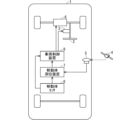
- FIG. 1 is a diagram showing the overall configuration of a vehicle equipped with a mobile body positioning device according to a first embodiment;
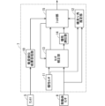
- FIG. 1 is a block diagram showing the configuration of a mobile object positioning device according to Embodiment 1.
- FIG. 5 is a flowchart showing processing of the mobile body positioning device according to the first embodiment.
- FIG. 3 is a schematic diagram showing a first motion model.
- FIG. 3 is a schematic diagram showing a second motion model.
- FIG. 3 is an explanatory diagram of a weighting function. It is a comparison diagram of a first motion model, a second motion model, and a mixed model.
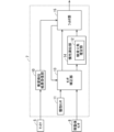
- FIG. 2 is a block diagram showing the configuration of a mobile body positioning device according to a modification of the first embodiment.
- FIG. 1 is a diagram showing the overall configuration of a vehicle equipped with a mobile body positioning device according to a first embodiment
- FIG. 1 is a block diagram showing the configuration of a mobile object positioning device according to Embodiment 1.
- FIG. 5 is
- FIG. 2 is a block diagram showing the configuration of a mobile body positioning device according to a modification of the first embodiment.
- FIG. 2 is a block diagram showing the configuration of a mobile body positioning device according to a modification of the first embodiment.
- FIG. 2 is a diagram showing the hardware configuration of a mobile positioning device.
- FIG. 2 is a diagram showing the hardware configuration of a mobile positioning device.
- FIG. 1 is a diagram showing the overall configuration of a vehicle 1 equipped with a mobile object positioning device 7 according to the first embodiment.
- Vehicle 1 is an example of a moving body.
- the vehicle 1 includes a steering wheel 2, a steering actuator 3, an antenna 5, a drive device 6, a mobile body positioning device 7, a mobile body sensor 8, and a vehicle control device 9.
- the vehicle 1 includes a brake for braking the vehicle 1.
- the steering actuator 3 is attached to the handle 2 that operates the two front tires.
- the steering actuator 3 includes, for example, an EPS (Electric Power Steering) motor and an ECU (Electronic Control Unit).
- the steering actuator 3 can control the rotation of the steering wheel 2 and the front wheels by operating according to a steering command from the vehicle control device 9.
- the steering actuator 3 performs steering control so that the vehicle 1 travels along the road according to a steering command value input from the vehicle control device 9.
- the drive device 6 is provided on the front wheel axle of the vehicle 1 and drives the vehicle 1.
- the drive device 6 includes, for example, a drive motor, an ECU, and a brake.
- the drive device 6 can brake and drive the vehicle 1 by operating according to a speed or acceleration command value input from the vehicle control device 9.
- the drive device 6 controls the braking and driving of the vehicle 1 in accordance with a speed or acceleration command value input from the vehicle control device 9 so that the vehicle 1 reaches a speed according to traffic conditions.
- the antenna 5 receives a satellite signal from the satellite 4 and transmits the received satellite signal to the mobile positioning device 7.
- the satellite 4 is composed of, for example, a plurality of GPS (Global Positioning System) satellites. However, the satellite 4 is not limited to a GPS satellite. Other positioning satellites such as GLONASS (Global Navigation Satellite System) can also be used as the satellite 4.
- GPS Global Positioning System
- GLONASS Global Navigation Satellite System
- the mobile body sensor 8 detects state quantities of the vehicle 1 such as steering angle or vehicle speed, and transmits the detected state quantities to the mobile body positioning device 7.
- the mobile body positioning device 7 measures the position of the vehicle 1 based on the satellite signal received by the antenna 5 and the state quantity of the vehicle 1 detected by the mobile body sensor 8, and transmits the measured position of the vehicle 1 to the vehicle control device. Send to 9.
- the vehicle control device 9 controls the steering actuator 3 based on the position of the vehicle 1 measured by the mobile body positioning device 7, the state quantity of the vehicle 1 detected by the mobile body sensor 8, and the recognition result of a camera or millimeter wave radar (not shown). and outputs a command value to the drive device 6.
- FIG. 2 is a block diagram showing the configuration of the mobile object positioning device 7 according to the first embodiment.
- the mobile positioning device 7 includes a satellite positioning result receiving section 10, an inertial sensor 11, a sideslip angle estimating section 12, a sensor correcting section 13, an inertial positioning section 14, and a filter section 15.
- the mobile body positioning device 7 includes a sensor information acquisition unit not shown in FIG.
- an antenna 5 and a mobile sensor 8 are connected to the mobile body positioning device 7 .
- the satellite positioning result receiving unit 10 converts the satellite signal output from the antenna 5 into data such as latitude, longitude, or direction, and outputs it to the filter unit 15 as a satellite positioning result.
- the satellite positioning results are expressed in a format that can be used within the mobile positioning device 7, such as GPGGA format.
- the inertial sensor 11 is an angular velocity sensor mounted on the mobile body positioning device 7, and outputs the angular velocity (yaw rate) generated as the vehicle 1 turns.
- the inertial sensor 11 is mounted on the mobile body positioning device 7.
- the inertial sensor 11 may be mounted on the vehicle 1 outside the mobile body positioning device 7, and the detection result may be input to the mobile body positioning device 7. This makes it possible to reduce the cost of the mobile body positioning device 7.
- the sideslip angle estimation unit 12 estimates the sideslip angle by weighting a plurality of motion models based on the vehicle speed and steering angle input from the moving object sensor 8 and the yaw rate input from the inertial sensor 11, and estimates the sideslip angle by weighting a plurality of motion models. Outputs the sideslip angle estimation results to.
- the sensor correction unit 13 acquires sensor values from the mobile sensor 8 and the inertial sensor 11, corrects sensor errors such as scale factors or biases included in the sensor values, and outputs the corrected sensor values to the inertial positioning unit 14 and the filter unit 15. . That is, the sensor correction unit 13 also functions as a sensor information acquisition unit that acquires sensor values from the moving object sensor 8 and the inertial sensor 11.
- the inertial positioning unit 14 uses the sensor values corrected by the sensor correction unit 13 to perform inertial positioning calculations on the position, attitude, speed, etc. that are the positioning results of the vehicle 1, and outputs the inertial positioning results to the filter unit 15. .
- the filter unit 15 uses the inertial positioning result input from the inertial positioning unit 14 to estimate the error between the inertial positioning result and the sensor value output by the mobile sensor 8.
- the sensor correction unit 13 acquires the inertial sensor value from the inertial sensor 11 and the mobile body sensor value from the mobile body sensor 8 in step S101.
- the inertial sensor value includes the current angular velocity and acceleration of the vehicle 1.
- Angular velocity includes yaw rate, pitch rate, and roll rate
- acceleration includes longitudinal acceleration, lateral acceleration, and vertical acceleration.
- the moving object sensor value includes the current steering angle and vehicle speed of the vehicle 1.
- step S102 the sensor correction unit 13 acquires the sensor correction value calculated in the previous cycle from the filter unit 15. If the previous sensor correction value does not exist for some reason, such as immediately after the power is turned on, the sensor correction unit 13 uses a preset initial value (0 or the value at the time of shipment).
- step S103 the sensor correction unit 13 uses the sensor correction value obtained in step S102 to correct the error in the inertial sensor value and the moving object sensor value obtained in step S101, and outputs it to the filter unit 15.
- step S104 the sideslip angle estimation unit 12 calculates the sideslip angle of the vehicle 1 based on the steering angle and vehicle speed of the vehicle 1 inputted from the moving object sensor 8, and the yaw rate of the vehicle 1 inputted from the inertial sensor 11. It is calculated and output to the inertial positioning section 14.
- the sideslip angle estimation unit 12 calculates the state of the vehicle 1 using a plurality of vehicle motion models and weighting functions. In this embodiment, a description will be given of how the sideslip angle estimation unit 12 calculates the state of the vehicle 1 using two vehicle motion models and one weighting function. However, the sideslip angle estimation unit 12 may use three or more vehicle motion models or may use a plurality of weighting functions when calculating the state of the vehicle 1.
- FIG. 4 is a diagram schematically representing the first motion model.
- the first motion model is a dynamic model using equations of motion of the vehicle in the lateral direction and rotation. According to this model, it is possible to calculate vehicle motion according to the force generated by the tires, so it can accurately represent vehicle motion at high vehicle speeds, especially when lateral acceleration occurs when turning.
- the vehicle state quantity x and input u in the first motion model f1 are set as follows.
- Equation (1) X, Y, and ⁇ represent the center of gravity position and azimuth of the vehicle 1 in the inertial coordinate system, V is the vehicle speed, ⁇ is the yaw rate, ⁇ is the sideslip angle, ⁇ is the front wheel steering angle, and ax is the Represents longitudinal acceleration.
- equation (2) ⁇ represents the front wheel steering angular velocity, and j x represents the longitudinal jerk.
- the first motion model f1 is expressed by the following equation using the variables of equations (1) and (2).
- M is the vehicle mass
- V is the vehicle speed
- I is the yaw moment of inertia of the vehicle
- l f is the distance between the vehicle center of gravity and the front axle
- l r is the distance between the vehicle center of gravity and the rear axle.
- Y f and Y r are the cornering forces of the front and rear wheels, and are expressed by the following formula using the cornering stiffnesses of the front and rear wheels K f and K r .
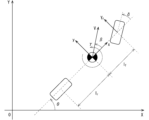
- FIG. 5 is a diagram schematically representing the second motion model.
- the second motion model is a geometric model derived from the geometric relationships of the vehicle. Unlike the first motion model, this model does not take into account the force generated by the tires, and can accurately represent vehicle motion at low vehicle speeds, such as when the vehicle turns along the direction of the tires.
- the vehicle state quantity x and input u of the second motion model are set to be the same as those of the first motion model.
- the second motion model f2 is expressed by the following equation using the variables of equations (1) and (2).
- ⁇ is a time constant of the yaw rate ⁇ and sideslip angle ⁇ , and different values may be used for the yaw rate ⁇ and sideslip angle ⁇ .
- ⁇ km and ⁇ km are the yaw rate and sideslip angle that can be calculated using a two-wheel model using geometric relationships, and are respectively expressed by the following formulas.
- the first motion model f 1 expressed by equation (6) and the second motion model f 2 expressed by equation (10) have the same vehicle state quantity x and input u, but with respect to yaw rate ⁇ and sideslip angle ⁇
- the differential equations are different. Note that the first motion model and the second motion model are not limited to the above models as long as they have the same vehicle state quantity x and input u and have different differential equations for at least one vehicle state quantity.
- the second motion model may be a dynamic model using equations of motion of the vehicle in the lateral direction and rotation during steady circular turning. Although this model cannot express transient motion unlike the first motion model, it can accurately represent vehicle motion at low vehicle speeds. Using this model, the second motion model is expressed by the following equation.
- ⁇ sst and ⁇ sst are the yaw rate and sideslip angle in steady circular turning, and are expressed by the following equations, respectively.
- A is called a stability factor and is expressed by the following formula.
- a model with good accuracy at high vehicle speeds is used as the first motion model
- a model with high accuracy at low vehicle speeds is used as the second motion model.
- the weighting function is a function that weights the first motion model and the second motion model, and is set to take a value between 0 and 1. Since the first motion model in this embodiment includes division by vehicle speed, the values diverge around 0 km/h and the accuracy around 0 km/h is poor.
- the second motion model is a model in which the yaw rate ⁇ and sideslip angle ⁇ are generated depending on the steering angle, and does not take into account the force generated in the vehicle. Therefore, the second motion model has poor accuracy at high vehicle speeds where centrifugal force is generated when turning. Therefore, the weighting function is set as a function of speed, and is expressed by the following equation so that the weight of the first motion model becomes larger at high speeds and the weight of the second motion model becomes larger at low speeds.
- An example of a weighting function based on this speed is shown in FIG.
- a new vehicle motion model f is constructed using the first motion model, the second motion model, and this weight function.
- This vehicle motion model f is constructed by a differential equation having the same vehicle state quantity x and input u as the first motion model f 1 and the second motion model f 2 .
- this vehicle motion model f will be referred to as a mixed model.
- the sideslip angle estimation unit 12 creates a mixed model by weighting a plurality of motion models based on the speed of the vehicle 1.
- the weighting function ⁇ is a function having a quadratic term of the vehicle speed V in the numerator and denominator, respectively.
- the weighting function ⁇ may be any function, such as a polynomial function or an exponential function, as long as it takes a value between 0 and 1.
- the weighting function ⁇ is a function using the vehicle speed V as a variable, it may be a function of different variables depending on the first motion model and the second motion model.
- a different weighting function ⁇ may be used for each vehicle state quantity to be calculated. For example, if the switching speed of the weighting function of the yaw rate ⁇ is V s1 and the switching speed of the weighting function of the sideslip angle ⁇ is V s2 , then the mixed model f is expressed as follows.
- the current sideslip angle ⁇ can be estimated.
- the sideslip angle ⁇ can be obtained continuously from when the vehicle is stopped to when the vehicle is at high speed, making it possible to accurately position the vehicle 1.
- step S105 the inertial positioning unit 14 uses the sensor correction value input from the sensor correction unit 13 to calculate and update the amount of change in the position and orientation of the vehicle 1, and filters the result as an inertial positioning result. output to section 15.
- the filter unit 15 uses the inertial measurement results and the satellite positioning results output from the satellite positioning result receiving unit 10 to calculate the inertial positioning results, the inertial sensor output, and the moving object sensor output.
- the error is estimated and output to the vehicle control device 9.
- step S106 the filter unit 15 determines whether the satellite positioning result has been updated in the current calculation cycle.
- the calculation cycle of satellite positioning is about the same or slower than the measurement cycles of the inertial sensor 11 and the moving object sensor 8. Therefore, if the satellite positioning result has not been updated, the filter unit 15 does not update the sensor correction amount for the inertial sensor 11 and the moving object sensor 8, and uses the previously estimated sensor correction amount, the inertial sensor value, and the moving object sensor. A positioning calculation result is output based on the sensor value and the sideslip angle estimation result (step S107).
- the filter unit 15 calculates the sensor correction amount using the satellite positioning result, the inertial sensor value, and the moving object sensor value (step S108).
- the filter unit 15 uses a filter configured with an extended Kalman filter to calculate the sensor correction amount of the inertial sensor 11 and the moving body sensor 8 against the error between the satellite positioning result and the inertial positioning result, which is called loose coupling. Use a filter to determine.
- the traveling direction ⁇ of the vehicle is expressed by the following equation using the azimuth angle ⁇ and sideslip angle ⁇ of the vehicle.
- the azimuth angle ⁇ of the vehicle is expressed by the following equation using equation (19).
- the inertial positioning unit 14 uses the azimuth angle ⁇ of the vehicle 1 in consideration of the sideslip angle ⁇ obtained in this manner, the inertial positioning unit 14 defines state variables as follows, for example, and calculates the inertial positioning result.
- Equation (21) represents a state vector related to inertial positioning that summarizes state variables related to inertial positioning.
- ⁇ d is the latitude obtained by the inertial positioning calculation
- ⁇ d is the longitude obtained by the inertial positioning calculation
- h d is the ellipsoid height obtained by the inertial positioning calculation
- ⁇ d is obtained by equation (20). Represents the azimuth angle considering the sideslip angle ⁇ .
- the inertial positioning result can be obtained by substituting y d and input u from one step before for , and performing moment-by-moment integration.
- the filter unit 15 estimates the state quantity and sensor error using a Kalman filter.
- the estimation is performed using the sensor model as shown below.
- Equation (22) is a model in which the true value V t of the vehicle speed is multiplied by the scale factor S v of the vehicle speed.
- Equation (23) is a model in which the bias b ⁇ of the yaw rate sensor is superimposed on the true value ⁇ t of the yaw rate, and multiplied by the scale factor s ⁇ of the yaw rate.
- the filter unit 15 estimates the respective estimated values s ve , s ⁇ e and b ⁇ e of s V , s ⁇ and b ⁇ as sensor errors.
- the sensor correction unit 13 uses the estimated value of the sensor error estimated by the filter unit 15 to correct the sensor values of the mobile sensor 8 and the inertial sensor 11 according to the following equation.
- the filter unit 15 defines a state vector as shown in the following equation.
- a dynamic model of the vehicle speed scale factor s V , the yaw rate scale factor s ⁇ , and the yaw rate sensor bias b ⁇ is expressed by the following equation. It is assumed that the system is driven by a first-order Markov process that predicts the next state from the current state.
- Equation 29) to (31) is the time derivative of s V , is the time derivative of s ⁇ , is the time derivative of b ⁇ .
- ⁇ sV is the model parameter value of the vehicle speed scale factor
- W sV is the noise related to the time transition of the vehicle speed scale factor
- ⁇ s ⁇ is the model parameter value of the yaw rate scale factor
- W s ⁇ is the noise related to the time transition of the yaw rate scale factor
- ⁇ b ⁇ is the model parameter value of the yaw rate bias
- w b ⁇ is the noise related to the time transition of the yaw rate bias.
- formula (32) represents a vector obtained by time-differentiating the state vector x. Also, u is the input vector represents.
- the satellite positioning result receiving unit 10 outputs coordinate information such as the latitude, longitude, and altitude of the antenna 5.
- the observed values of the GNSS sensor are assumed to be ( ⁇ m , ⁇ m , h m , ⁇ m ).
- these coordinate information can also be obtained from the inertial positioning results, but since the inertial positioning results are the coordinates of the navigation center of the vehicle, the offset amount from the vehicle navigation center to the position of the antenna 5 is used to calculate the observation of the GNSS sensor. Value is predicted.
- the offset amount from the vehicle navigation center to the antenna 5 expressed in the vehicle navigation coordinate system is ( ⁇ x, ⁇ y, ⁇ z)
- the predicted observed values of the GNSS sensor ( ⁇ p , ⁇ p , h p , ⁇ p ) is obtained from the inertial positioning value y d and the offset amount v ( ⁇ x, ⁇ y, ⁇ z) using the coordinate transformation function c (y d , v) as shown in the following equation (33).
- the accuracy of the inertial positioning result is improved, and the accuracy of the state quantity and sensor error estimation in the filter section 15 is also improved.
- the mobile body positioning device 7 uses a steering angle of the vehicle 1 detected by the mobile body sensor 8 and the inertial sensor 11, which are sensors mounted on the vehicle 1, which is a mobile body. , a sensor information acquisition unit that acquires sensor values including vehicle speed and angular velocity, an inertial positioning unit 14 that performs inertial positioning of the vehicle 1 using the sensor values, and a sideslip angle that estimates the sideslip angle of the vehicle 1 using the sensor values. and an estimator 12. Then, the sideslip angle estimating unit 12 generates a mixture obtained by weighting and integrating a plurality of motion models f1 and f2 having different differential equations for at least one state quantity of the vehicle 1 based on the state quantity of the vehicle 1.
- the sideslip angle is estimated based on the model f and the sensor values. Therefore, according to the mobile body positioning device 7, it is possible to accurately estimate the sideslip angle of the vehicle 1 even when the vehicle 1 is not in a steady state, and the position and orientation of the vehicle 1 can be accurately estimated. Thereby, for example, when the mobile body positioning device 7 is used for an application such as automatic driving, the control safety and ride comfort of the vehicle 1 are improved.
- the mobile object positioning device 7 also includes a filter unit 15 that estimates a sensor error included in the sensor value using the results of inertial positioning and the sideslip angle, and a sensor correction unit 13 that corrects the sensor error included in the sensor value. , and the inertial positioning section 14 may perform inertial positioning using the sensor value corrected by the sensor correction section 13.
- the sensor values of the moving body sensor 8 and the inertial sensor 11 are input to the sideslip angle estimation unit 12.
- the sensor value corrected by the sensor correction section 13 may be input to the sideslip angle estimation section 12. That is, the sideslip angle estimation unit 12 may estimate the sideslip angle based on the sensor value corrected by the sensor correction unit 13. This reduces the error included in the input to the sideslip angle estimation unit 12 and improves the accuracy of estimating the sideslip angle.
- the sideslip angle estimation result by the sideslip angle estimation unit 12 is output to the filter unit 15.
- the sideslip angle estimation result by the sideslip angle estimation unit 12 may be output to the inertial positioning unit 14. That is, the inertial positioning unit 14 may use the sideslip angle to perform inertial positioning in consideration of the sideslip angle.
- the observed values of the GNSS sensor ( ⁇ m , ⁇ m , h m , ⁇ m ) are converted into values that take into account the sideslip angle ⁇ , that is, ( ⁇ m , ⁇ m , h m , ⁇ m - ⁇ ).
- the inertial positioning unit 14 performs an inertial positioning calculation in consideration of the sideslip angle ⁇ . This improves the accuracy of estimating the azimuth angle by inertial positioning.
- the inertial positioning section 14 may include a sideslip angle estimating section 12. That is, the model used for estimating the sideslip angle in the sideslip angle estimation section 12 may be used for the calculation of inertial positioning in the inertial positioning section 14.
- the mobile body positioning device 7 includes a sensor information acquisition unit that acquires sensor values including the steering angle, vehicle speed, and angular velocity of the vehicle 1 detected by the mobile body sensor 8 and the inertial sensor 11, which are sensors mounted on the vehicle 1. , a sensor correction unit 13 that corrects sensor errors included in sensor values, an inertial positioning unit 14 that performs inertial positioning of the vehicle 1 using the sensor values corrected by the sensor correction unit 13, and a result of inertial positioning and movement.
- the inertial positioning unit 14 may also include a filter unit 15 that estimates a sensor error included in the sensor value using the sideslip angle of the body.
- the inertial positioning unit 14 also generates a mixed model obtained by weighting and integrating a plurality of motion models f1 and f2 having different differential equations for at least one state quantity of the vehicle 1 based on the state quantity of the vehicle 1.
- the sideslip angle may be estimated based on f and the sensor value.
- the input to the Kalman filter The front wheel steering angle ⁇ is added to the equation of state used in the Kalman filter.
- the model of the azimuth angle ⁇ of the vehicle 1 in instead of just integrating the yaw rate, may be a more detailed model as shown in equation (18).
- the latitude, longitude, altitude, azimuth, etc. calculated by the GNSS sensor are used as observed values by GNSS.
- some GNSS sensors can output raw data such as pseudorange, Doppler, and carrier phase, tight coupling may be used that uses these as observed values.
- the number of visible satellites is small, such as only one, it is possible to generate observed values by GNSS. This enables highly accurate positioning even when the number of visible satellites is small.
- the filter unit 15 estimates the traveling direction of the vehicle 1 based on the satellite signals received from the satellites 4 by the plurality of antennas 5 mounted on the vehicle 1, and calculates the sideslip angle and the traveling direction of the vehicle 1 as a result of inertial positioning. Estimate the sensor error based on Thereby, the filter unit 15 can calculate the movement or rotation of the vehicle from the mutual positions of the antennas 5, and can estimate the direction with higher accuracy.
- the satellite positioning result receiving section 10, sideslip angle estimating section 12, sensor correcting section 13, inertial positioning section 14, and filter section 15 in the mobile body positioning device 7 described above are realized by a processing circuit 81 shown in FIG. That is, the processing circuit 81 includes a satellite positioning result receiving section 10, a sideslip angle estimation section 12, a sensor correction section 13, an inertial positioning section 14, and a filter section 15 (hereinafter referred to as "sideslip angle estimation section 12, etc.”).
- Dedicated hardware may be applied to the processing circuit 81, or a processor that executes a program stored in memory may be applied.
- the processor is, for example, a central processing unit, a processing unit, an arithmetic unit, a microprocessor, a microcomputer, a DSP (Digital Signal Processor), or the like.
- the processing circuit 81 may be, for example, a single circuit, a composite circuit, a programmed processor, a parallel programmed processor, an ASIC (Application Specific Integrated Circuit), or an FPGA (Field-Programmable Circuit). Gate Array), or a combination of these.
- the functions of each section such as the sideslip angle estimation section 12 may be realized by a plurality of processing circuits 81, or the functions of each section may be realized by a single processing circuit.
- the processing circuit 81 When the processing circuit 81 is a processor, the functions of the sideslip angle estimation unit 12 and the like are realized by a combination of software and the like (software, firmware, or software and firmware). Software etc. are written as programs and stored in memory. As shown in FIG. 12, a processor 82 applied to a processing circuit 81 realizes the functions of each part by reading and executing a program stored in a memory 83. That is, the mobile body positioning device 7 includes a memory 83 for storing a program that, when executed by the processing circuit 81, results in the functions of each part of the mobile body positioning device 7 being executed. In other words, this program can be said to cause the computer to execute the procedures or methods of the sideslip angle estimation unit 12 and the like.
- the memory 83 is a non-volatile or Volatile semiconductor memory, HDD (Hard Disk Drive), magnetic disk, flexible disk, optical disk, compact disk, mini disk, DVD (Digital Versatile Disk) and its drive device, etc., or any storage media that will be used in the future. It's okay.
- HDD Hard Disk Drive
- magnetic disk flexible disk
- optical disk compact disk
- mini disk mini disk
- DVD Digital Versatile Disk
- each function of the sideslip angle estimating unit 12 and the like is realized by either hardware, software, etc.
- the present invention is not limited to this, and a configuration may be adopted in which a part of the sideslip angle estimating section 12 and the like is realized by dedicated hardware, and another part is realized by software or the like.
- vehicle 1 is illustrated as a moving object, the moving object is not limited to a vehicle.
- mobile objects include various inspection robots and personal mobility devices.
- 1 Vehicle 1 Vehicle, 2 Steering wheel, 3 Steering actuator, 4 Satellite, 5 Antenna, 6 Drive device, 7 Mobile positioning device, 8 Mobile sensor, 9 Vehicle control device, 10 Satellite positioning result receiving unit, 11 Inertial sensor, 12 Side slip angle Estimation unit, 13 sensor correction unit, 14 inertial positioning unit, 15 filter unit.
Landscapes
- Engineering & Computer Science (AREA)
- Radar, Positioning & Navigation (AREA)
- Remote Sensing (AREA)
- Automation & Control Theory (AREA)
- Physics & Mathematics (AREA)
- General Physics & Mathematics (AREA)
- Mathematical Physics (AREA)
- Transportation (AREA)
- Mechanical Engineering (AREA)
- Navigation (AREA)
- Control Of Driving Devices And Active Controlling Of Vehicle (AREA)
Abstract
Description
<A-1.構成>
図1は実施の形態1に係る移動体測位装置7を搭載した車両1の全体構成を示す図である。車両1は移動体の例である。図1に示されるように車両1は、ハンドル2、操舵アクチュエータ3、アンテナ5、駆動装置6、移動体測位装置7、移動体センサ8および車両制御装置9を備える。また、図1には図示されていないが、車両1は車両1を制動させるためのブレーキを備える。
次に図3に示すフローチャートを用いて実施の形態1の移動体測位装置7の処理フローについて説明する。

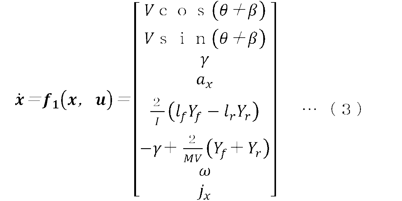



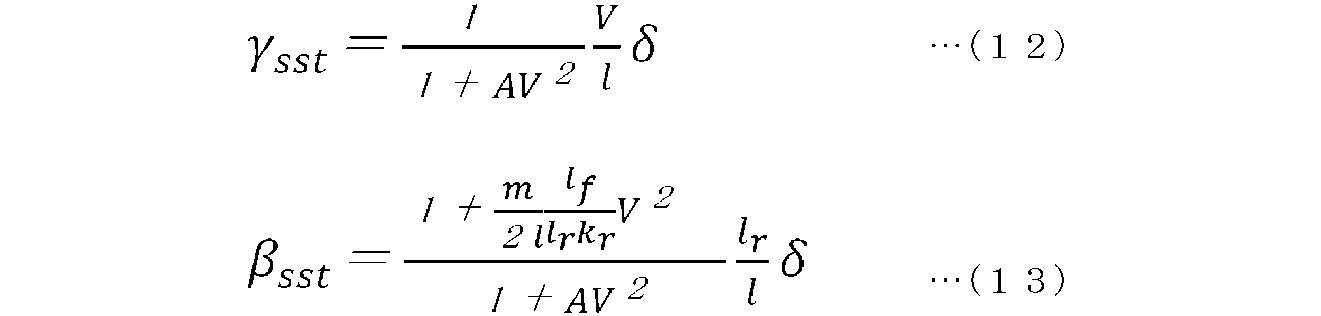



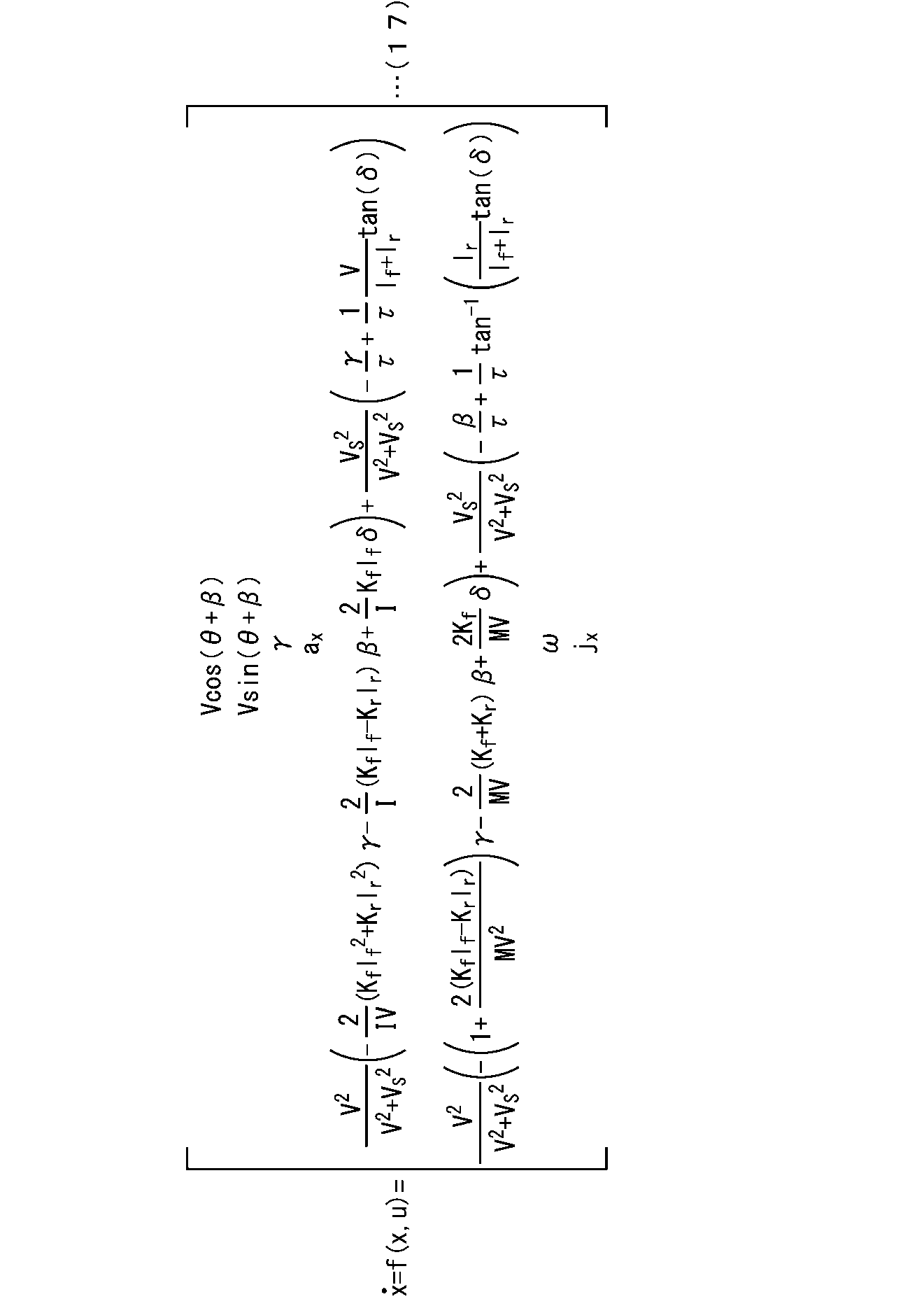







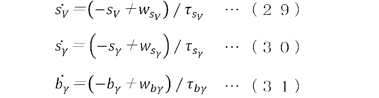






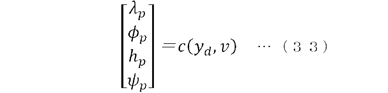
図2に示される構成では、移動体センサ8および慣性センサ11のセンサ値が横滑り角推定部12に入力された。しかし、図8に示されるように、センサ補正部13により補正されたセンサ値が横滑り角推定部12に入力されてもよい。すなわち、横滑り角推定部12は、センサ補正部13で補正されたセンサ値に基づき横滑り角を推定してもよい。これにより、横滑り角推定部12の入力に含まれる誤差が小さくなり、横滑り角の推定精度が向上する。


上述した移動体測位装置7における、衛星測位結果受信部10、横滑り角推定部12、センサ補正部13、慣性測位部14およびフィルタ部15は、図11に示す処理回路81により実現される。すなわち、処理回路81は、衛星測位結果受信部10、横滑り角推定部12、センサ補正部13、慣性測位部14およびフィルタ部15(以下、「横滑り角推定部12等」と称する)を備える。処理回路81には、専用のハードウェアが適用されても良いし、メモリに格納されるプログラムを実行するプロセッサが適用されても良い。プロセッサは、例えば中央処理装置、処理装置、演算装置、マイクロプロセッサ、マイクロコンピュータ、DSP(Digital Signal Processor)等である。
Claims (7)
- センサにより検出された移動体に関するセンサ値を取得するセンサ情報取得部と、
前記センサ値を用いて前記移動体の横滑り角を推定する横滑り角推定部と、
前記センサ値と前記横滑り角とを用いて前記移動体の慣性測位を行う慣性測位部と、を備え、
前記横滑り角推定部は、前記移動体に関する複数の運動モデルを前記移動体の状態量に基づき重みづけして統合することにより得られた混合モデルと、前記センサ値とに基づき、前記横滑り角を推定する、
移動体測位装置。 - センサにより検出された移動体に関するセンサ値を取得するセンサ情報取得部と、
前記センサ値に含まれるセンサ誤差を補正するセンサ補正部と、
前記センサ補正部で補正された前記センサ値を用いて前記移動体の慣性測位を行う慣性測位部と、
前記慣性測位の結果および前記移動体の横滑り角を用いて、前記センサ値に含まれるセンサ誤差を推定するフィルタ部と、を備え、
前記慣性測位部は、前記移動体に関する複数の運動モデルを前記移動体の状態量に基づき重みづけして統合することにより得られた混合モデルと、前記センサ値とに基づき、前記横滑り角を推定し、前記横滑り角を用いて前記慣性測位を行う、
移動体測位装置。 - 前記慣性測位の結果および前記横滑り角を用いて、前記センサ値に含まれるセンサ誤差を推定するフィルタ部と、
前記センサ値に含まれるセンサ誤差を補正するセンサ補正部と、を備え、
前記慣性測位部は前記センサ補正部で補正された前記センサ値を用いて前記慣性測位を行う、
請求項1に記載の移動体測位装置。 - 前記横滑り角推定部は、前記センサ補正部で補正された前記センサ値を用いて前記横滑り角を推定する、
請求項3に記載の移動体測位装置。 - 前記横滑り角推定部は、前記移動体の速度に基づいて前記複数の運動モデルを重みづけして前記混合モデルを作成する、
請求項1,3,4のいずれか1項に記載の移動体測位装置。 - 前記フィルタ部は、前記移動体に搭載された複数のアンテナが衛星から受信した衛星信号により、前記移動体の進行方向を推定し、前記慣性測位の結果、前記横滑り角、および前記移動体の進行方向に基づき、前記センサ誤差を推定する、
請求項2から請求項4のいずれか1項に記載の移動体測位装置。 - 前記慣性測位部は、前記移動体の速度に基づいて前記複数の運動モデルを重みづけして前記混合モデルを作成する、
請求項2に記載の移動体測位装置。
Priority Applications (4)
| Application Number | Priority Date | Filing Date | Title |
|---|---|---|---|
| JP2022562447A JP7262684B1 (ja) | 2022-05-10 | 2022-05-10 | 移動体測位装置 |
| PCT/JP2022/019805 WO2023218526A1 (ja) | 2022-05-10 | 2022-05-10 | 移動体測位装置 |
| US18/861,897 US20250327667A1 (en) | 2022-05-10 | 2022-05-10 | Mobile object positioning device |
| DE112022007174.5T DE112022007174T5 (de) | 2022-05-10 | 2022-05-10 | Positionierungseinrichtung für mobile objekte |
Applications Claiming Priority (1)
| Application Number | Priority Date | Filing Date | Title |
|---|---|---|---|
| PCT/JP2022/019805 WO2023218526A1 (ja) | 2022-05-10 | 2022-05-10 | 移動体測位装置 |
Publications (1)
| Publication Number | Publication Date |
|---|---|
| WO2023218526A1 true WO2023218526A1 (ja) | 2023-11-16 |
Family
ID=86052890
Family Applications (1)
| Application Number | Title | Priority Date | Filing Date |
|---|---|---|---|
| PCT/JP2022/019805 Ceased WO2023218526A1 (ja) | 2022-05-10 | 2022-05-10 | 移動体測位装置 |
Country Status (4)
| Country | Link |
|---|---|
| US (1) | US20250327667A1 (ja) |
| JP (1) | JP7262684B1 (ja) |
| DE (1) | DE112022007174T5 (ja) |
| WO (1) | WO2023218526A1 (ja) |
Citations (3)
| Publication number | Priority date | Publication date | Assignee | Title |
|---|---|---|---|---|
| JPH09311042A (ja) * | 1996-05-22 | 1997-12-02 | Toyota Central Res & Dev Lab Inc | 車体横すべり角検出装置 |
| JP2020125058A (ja) * | 2019-02-06 | 2020-08-20 | 日産自動車株式会社 | 車両の旋回姿勢制御方法及び旋回姿勢制御装置 |
| JP2022065602A (ja) * | 2020-10-15 | 2022-04-27 | Ntn株式会社 | 車両姿勢制御装置および車両 |
Family Cites Families (6)
| Publication number | Priority date | Publication date | Assignee | Title |
|---|---|---|---|---|
| JPH1178933A (ja) * | 1997-09-08 | 1999-03-23 | Nissan Motor Co Ltd | 車両の車体横滑り角推定方法及び推定装置 |
| EP2999940A4 (en) * | 2013-05-22 | 2017-11-15 | Neurala Inc. | Methods and apparatus for early sensory integration and robust acquisition of real world knowledge |
| JP2020112490A (ja) | 2019-01-15 | 2020-07-27 | 株式会社豊田中央研究所 | 自己位置推定装置及びプログラム |
| JP7391293B2 (ja) * | 2020-04-17 | 2023-12-05 | マツダ株式会社 | 車両制御装置 |
| JP7518914B2 (ja) * | 2020-10-30 | 2024-07-18 | 日立Astemo株式会社 | 車両制御装置 |
| CN117571001A (zh) * | 2021-01-08 | 2024-02-20 | 御眼视觉技术有限公司 | 用于公共速度映射和导航的系统和方法 |
-
2022
- 2022-05-10 US US18/861,897 patent/US20250327667A1/en active Pending
- 2022-05-10 WO PCT/JP2022/019805 patent/WO2023218526A1/ja not_active Ceased
- 2022-05-10 DE DE112022007174.5T patent/DE112022007174T5/de active Pending
- 2022-05-10 JP JP2022562447A patent/JP7262684B1/ja active Active
Patent Citations (3)
| Publication number | Priority date | Publication date | Assignee | Title |
|---|---|---|---|---|
| JPH09311042A (ja) * | 1996-05-22 | 1997-12-02 | Toyota Central Res & Dev Lab Inc | 車体横すべり角検出装置 |
| JP2020125058A (ja) * | 2019-02-06 | 2020-08-20 | 日産自動車株式会社 | 車両の旋回姿勢制御方法及び旋回姿勢制御装置 |
| JP2022065602A (ja) * | 2020-10-15 | 2022-04-27 | Ntn株式会社 | 車両姿勢制御装置および車両 |
Also Published As
| Publication number | Publication date |
|---|---|
| JP7262684B1 (ja) | 2023-04-21 |
| JPWO2023218526A1 (ja) | 2023-11-16 |
| DE112022007174T5 (de) | 2025-03-06 |
| US20250327667A1 (en) | 2025-10-23 |
Similar Documents
| Publication | Publication Date | Title |
|---|---|---|
| JP7036080B2 (ja) | 慣性航法装置 | |
| Tin Leung et al. | A review of ground vehicle dynamic state estimations utilising GPS/INS | |
| CN106289275B (zh) | 用于改进定位精度的单元和方法 | |
| US8775063B2 (en) | System and method of lane path estimation using sensor fusion | |
| US7096116B2 (en) | Vehicle behavior detector, in-vehicle processing system, detection information calibrator, and in-vehicle processor | |
| EP2856273B1 (en) | Pose estimation | |
| CN114076610A (zh) | Gnss/mems车载组合导航系统的误差标定、导航方法及其装置 | |
| CN110346824B (zh) | 一种车辆导航方法、系统、装置及可读存储介质 | |
| Jo et al. | Integration of multiple vehicle models with an IMM filter for vehicle localization | |
| US11787418B1 (en) | Systems and methods for real-time tractor-trailer mass estimation | |
| US7164985B2 (en) | Vehicle-direction estimating device, and driving control device including the vehicle-direction estimating device | |
| JP4854778B2 (ja) | 車両用推定航法装置、車両用推定航法及び車両用推定航法のプログラム | |
| US12428002B2 (en) | Method for determining an integrity range | |
| US20220340123A1 (en) | Vehicle control device and vehicle control method | |
| Ando et al. | Localization using global magnetic positioning system for automated driving bus and intervals for magnetic markers | |
| US12215976B2 (en) | Estimation device, estimation method, program product for estimation | |
| Kang et al. | Vehicle lateral motion estimation with its dynamic and kinematic models based interacting multiple model filter | |
| Choi et al. | Position estimation in urban u-turn section for autonomous vehicles using multiple vehicle model and interacting multiple model filter | |
| JP7407947B2 (ja) | 車両制御装置 | |
| CN116499472B (zh) | 一种兼顾车辆动力学和非完整约束的融合定位方法 | |
| Seyr et al. | Proprioceptive navigation, slip estimation and slip control for autonomous wheeled mobile robots | |
| Chen et al. | An integrated GNSS/INS/DR positioning strategy considering nonholonomic constraints for intelligent vehicle | |
| JP7069624B2 (ja) | 位置演算方法、車両制御方法及び位置演算装置 | |
| JP7262684B1 (ja) | 移動体測位装置 | |
| CN118816941A (zh) | 一种外参标定方法、装置及车辆 |
Legal Events
| Date | Code | Title | Description |
|---|---|---|---|
| ENP | Entry into the national phase |
Ref document number: 2022562447 Country of ref document: JP Kind code of ref document: A |
|
| 121 | Ep: the epo has been informed by wipo that ep was designated in this application |
Ref document number: 22941608 Country of ref document: EP Kind code of ref document: A1 |
|
| WWE | Wipo information: entry into national phase |
Ref document number: 18861897 Country of ref document: US |
|
| WWE | Wipo information: entry into national phase |
Ref document number: 112022007174 Country of ref document: DE |
|
| WWP | Wipo information: published in national office |
Ref document number: 112022007174 Country of ref document: DE |
|
| 122 | Ep: pct application non-entry in european phase |
Ref document number: 22941608 Country of ref document: EP Kind code of ref document: A1 |
|
| WWP | Wipo information: published in national office |
Ref document number: 18861897 Country of ref document: US |