WO2023218519A1 - ネットワーク設備監視装置、ネットワーク設備監視方法およびプログラム - Google Patents
ネットワーク設備監視装置、ネットワーク設備監視方法およびプログラム Download PDFInfo
- Publication number
- WO2023218519A1 WO2023218519A1 PCT/JP2022/019777 JP2022019777W WO2023218519A1 WO 2023218519 A1 WO2023218519 A1 WO 2023218519A1 JP 2022019777 W JP2022019777 W JP 2022019777W WO 2023218519 A1 WO2023218519 A1 WO 2023218519A1
- Authority
- WO
- WIPO (PCT)
- Prior art keywords
- alarm
- repeated
- information
- network equipment
- warning
- Prior art date
- Legal status (The legal status is an assumption and is not a legal conclusion. Google has not performed a legal analysis and makes no representation as to the accuracy of the status listed.)
- Ceased
Links
Images










Classifications
-
- H—ELECTRICITY
- H04—ELECTRIC COMMUNICATION TECHNIQUE
- H04L—TRANSMISSION OF DIGITAL INFORMATION, e.g. TELEGRAPHIC COMMUNICATION
- H04L41/00—Arrangements for maintenance, administration or management of data switching networks, e.g. of packet switching networks
- H04L41/06—Management of faults, events, alarms or notifications
- H04L41/0631—Management of faults, events, alarms or notifications using root cause analysis; using analysis of correlation between notifications, alarms or events based on decision criteria, e.g. hierarchy, tree or time analysis
-
- H—ELECTRICITY
- H04—ELECTRIC COMMUNICATION TECHNIQUE
- H04L—TRANSMISSION OF DIGITAL INFORMATION, e.g. TELEGRAPHIC COMMUNICATION
- H04L41/00—Arrangements for maintenance, administration or management of data switching networks, e.g. of packet switching networks
- H04L41/06—Management of faults, events, alarms or notifications
- H04L41/069—Management of faults, events, alarms or notifications using logs of notifications; Post-processing of notifications
-
- H—ELECTRICITY
- H04—ELECTRIC COMMUNICATION TECHNIQUE
- H04L—TRANSMISSION OF DIGITAL INFORMATION, e.g. TELEGRAPHIC COMMUNICATION
- H04L41/00—Arrangements for maintenance, administration or management of data switching networks, e.g. of packet switching networks
- H04L41/06—Management of faults, events, alarms or notifications
- H04L41/0631—Management of faults, events, alarms or notifications using root cause analysis; using analysis of correlation between notifications, alarms or events based on decision criteria, e.g. hierarchy, tree or time analysis
- H04L41/064—Management of faults, events, alarms or notifications using root cause analysis; using analysis of correlation between notifications, alarms or events based on decision criteria, e.g. hierarchy, tree or time analysis involving time analysis
-
- H—ELECTRICITY
- H04—ELECTRIC COMMUNICATION TECHNIQUE
- H04L—TRANSMISSION OF DIGITAL INFORMATION, e.g. TELEGRAPHIC COMMUNICATION
- H04L41/00—Arrangements for maintenance, administration or management of data switching networks, e.g. of packet switching networks
- H04L41/06—Management of faults, events, alarms or notifications
- H04L41/0677—Localisation of faults
-
- H—ELECTRICITY
- H04—ELECTRIC COMMUNICATION TECHNIQUE
- H04L—TRANSMISSION OF DIGITAL INFORMATION, e.g. TELEGRAPHIC COMMUNICATION
- H04L41/00—Arrangements for maintenance, administration or management of data switching networks, e.g. of packet switching networks
- H04L41/22—Arrangements for maintenance, administration or management of data switching networks, e.g. of packet switching networks comprising specially adapted graphical user interfaces [GUI]
Definitions
- the present invention relates to network equipment monitoring technology for optical transmission systems, and particularly relates to a network equipment monitoring device, a network equipment monitoring method, and a program.
- Non-Patent Document 1 Conventionally, techniques for realizing system monitoring, alert notification, performance visualization, etc. are known (see Non-Patent Document 1 and Non-Patent Document 2).
- the monitoring device described in Non-Patent Document 1 determines a threshold value by collecting data from a monitoring target such as a network facility, performs an alert notification action, and stores various data in a database.
- a network equipment monitoring device includes an alarm database that stores, as alarm information, an abnormality detection alarm that notifies the occurrence of an abnormality and a recovery detection alarm that notifies the recovery of the abnormality output from the network equipment of an optical transmission system; An alarm reaping unit that periodically reaps accumulated alarm information and sends it to a predetermined notification destination, and an abnormality detection alarm and recovery detection alarm for the same alarm content of the same network equipment within a predetermined time from the alarm database.
- a repeated alarm extraction unit that extracts a group of alarms that have been repeatedly generated a predetermined number of times as repeated alarms, an occurrence recovery alarm pattern database that stores information on repeated alarms in past cases together with the causes of the repeated alarms, and the extracted repeats.
- An alarm pattern that compares the information of the alarm with the information of the repeated alarm of the past case and, if it is determined that the similarity is higher than a predetermined threshold, notifies the cause of the repeat alarm of the past case to the predetermined notification destination.
- the present invention is characterized by comprising a collation unit.
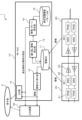
- FIG. 1 is a schematic configuration diagram of an optical transmission system including a network equipment monitoring device according to the present embodiment.
- FIG. 2 is a diagram illustrating an example of past occurrence/recovery repetition warnings that serve as basic information registered in the occurrence/recovery warning pattern database of FIG. 1; It is a graph which shows the time change of a repeated warning.
- FIG. 7 is a diagram showing a repeating pattern in which the cycle of repeating alarms is short.
- FIG. 7 is a diagram showing a repeating pattern in which a repeating alarm cycle is long.
- FIG. 7 is a diagram illustrating a repeating pattern in which the amount of variation in the cycle of repeating alarms is small.
- FIG. 7 is a diagram illustrating a repeating pattern in which there is a large amount of variation in the cycle of repeated warnings.
- FIG. 7 is a diagram illustrating a repeating pattern in which the ratio of the abnormality duration period to the cycle of repeated alarms is large. It is a figure which shows the data of the alarm group recorded in the alarm database. It is a figure which shows the information of the repeated warning extracted from the warning database.
- FIG. 6 is a diagram showing recorded data of candidates narrowed down from the occurrence recovery warning pattern database.
- 1 is a hardware configuration diagram showing an example of a computer that implements the functions of the network equipment monitoring device and each device according to the present embodiment;
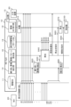
- FIG. FIG. 2 is a schematic diagram showing the flow of monitoring processing by the network equipment monitoring device according to the present embodiment.
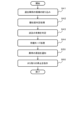
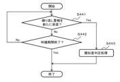
- FIG. 9 is a flowchart showing the flow of the similarity determination process in FIG. 8; 9 is a flowchart showing the flow of standby mode processing in FIG. 8; FIG. 2 is a schematic diagram showing an operation in which a conventional network equipment monitoring device notifies an abnormality detection alarm and a recovery detection alarm.
- the optical transmission system 1 includes a network equipment monitoring device 10, a network equipment 20, and a host device 30.
- the network equipment monitoring device 10 is configured with, for example, an NE-OpS (Network element operation system), and notifies the higher-level device 30 of alarms acquired from the network equipment 20, and also identifies the cause of abnormalities in past cases as necessary.
- the host device 30 is notified.
- the host device 30 is a device that monitors the network equipment monitoring device 10 and presents warnings and the like to the maintenance person 2.
- the network equipment 20 includes, for example, a transponder (TPND) 21, a wavelength selective switch (WSS) 22, and an optical amplifier (AMP) 23.
- TPND transponder
- WSS wavelength selective switch
- AMP optical amplifier
- this optical signal is converted into an optical signal by the transponder 21, multiplexed by the wavelength selective switch 22, and amplified by the optical amplifier 23. After that, it is sent to the outside.
- This optical signal is, for example, amplified by the optical amplification unit 23 of the network equipment NE2, demultiplexed by the wavelength selective switch 22, received by the transponder 21, and transmitted to a communication device (not shown). Note that this optical transmission system 1 is bidirectional communication.
- the network equipment monitoring device 10 includes an alarm database 11, an alarm harvesting section 12, a GUI (Graphical User Interface) section 13, a repeated alarm extraction section 14, an occurrence recovery alarm pattern database 15, an alarm pattern matching section 16, It is equipped with These units may be housed in the same casing called the network equipment monitoring device, or may be housed in different casings. Note that in the following description and drawings, the database will be referred to as DB.
- the alarm DB 11 stores, as alarm information, an abnormality detection alarm that notifies the occurrence of an abnormality and a recovery detection alarm that notifies the recovery from the abnormality, which are output from the network equipment 20 of the optical transmission system 1.
- the alarm DB 11 accumulates raw alarm data.
- the alarm harvesting unit 12 periodically harvests the alarm information accumulated in the alarm DB 11 and transmits it to a predetermined notification destination such as the host device 30.
- the GUI unit 13 presents predetermined information such as warnings to the user.
- the GUI unit 13 receives a user's instruction from an input device such as a mouse, and outputs information according to the user's instruction to an output device such as a display.
- the alarm DB 11, the alarm harvesting section 12, and the GUI section 13 have conventionally known configurations, so further explanation will be omitted.
- the repeated alarm extraction unit 14 extracts from the alarm DB 11 a group of alarms in which abnormality detection alarms and recovery detection alarms are repeatedly generated a predetermined number of times within a predetermined time for the same alarm content of the same network equipment as repeat alarms.
- the occurrence recovery alarm pattern DB 15 accumulates information on repeated alarms of past cases together with the cause of the repeated alarms.
- the alarm pattern matching unit 16 matches the information on the repeated alarm extracted by the repeated alarm extraction unit 14 with the information on the repeated alarms of past cases, and if it is determined that the similarity is higher than a predetermined threshold, the information on the repeated alarms extracted by the repeated alarm extraction unit 14 is The cause of the repeated alarm is notified to a predetermined notification destination.
- the cause of the alarm is not the content of the alarm, but the real reason why the alarm occurred, and refers to the cause of the abnormality in the network equipment.
- the occurrence recovery alarm pattern DB 15, the repeated alarm extraction section 14, and the alarm pattern matching section 16 will be described in detail.
- the information on the repeated warning of the past case includes basic information, the cause of the abnormality regarding the repeated warning of the past case, and statistical information.
- the basic information includes alarm content information, identification information of the network equipment where the alarm occurred, and information specifying the location where the alarm occurred. These pieces of information are recorded in association with the time information of the abnormality detection alarm or recovery detection alarm.
- FIG. 2 is a diagram illustrating an example of past occurrence/recovery repetition warnings that serve as basic information registered in the occurrence/recovery warning pattern DB 15.
- Basic information 210 shown in FIG. 2 includes information regarding items 211-215.
- Item 211 indicates the date and time when the alarm occurred. The date and time is expressed in, for example, year, month, day, hour, minute, and second.
- Item 212 indicates the type of alarm. In this example, "occurrence" represents an abnormality detection alarm, and "recovery" represents a recovery detection alarm. Note that in item 211, time t0 indicates the date and time when the first abnormality detection alarm in this repeated alarm occurred. Further, time t1 indicates the date and time when the first recovery detection alarm in this repeated alarm was issued.
- Item 213 indicates the content of the warning. LOS stands for loss of signal. Item 214 indicates the name of the device that outputs the alarm. OXC stands for optical cross-connect. Item 215 indicates the location where the alarm occurred. 10G path CH03 represents 10 Giga bits per second path channel 03. Note that the values of each item of the basic information 210 are merely examples.
- the cause of the abnormality regarding the repeated alarm in the past case is, for example, a failure of the wavelength selective switch (WSS) 22 or a failure of the optical amplification unit (AMP) 23.
- WSS wavelength selective switch
- AMP optical amplification unit
- a wavelength selective switch WSS
- alarms such as LOS, recovery, LOS, recovery, etc. are repeated in the predetermined network equipment 20.
- AMP optical amplifier
- an event occurs in which alarms such as LOS, recovery, LOS, recovery, etc. are repeated in a predetermined network equipment 20, and LOS, recovery, etc. alarms occur in other network equipment 20 as well.
- Recovery, LOS, recovery,... alarms are repeated.
- repeated warnings may spread to other devices.
- Spreading is an event in which, for example, a single cause, such as a failure of an optical amplification unit, repeatedly generates warnings regarding an abnormality from multiple locations.
- the statistical information registered in the occurrence/recovery warning pattern DB 15 is information calculated using time information as feature information of the repetition pattern regarding repeated warnings of past cases.
- the repeating pattern will be explained with reference to FIG. 3A.
- FIG. 3A is a graph showing changes in repeated warnings over time.
- the horizontal axis is the time axis and shows time information of repeated warnings.
- the vertical axis shows the type of alarm in binary form.
- An abnormality detection alarm is represented by 1, and a recovery detection alarm is represented by 0.
- 3B to 3F are diagrams showing other repeating patterns. Details of these repeating patterns will be described later.
- an abnormality continuation period The period from the generation time of the abnormality detection alarm to the generation time of the recovery detection alarm is called the recovery continuation period.
- the period that is the sum of the abnormality duration period and the subsequent recovery duration period is called a cycle.
- a period T1 from time t0 to time t1 is the first abnormality continuation period.
- a period T2 from time t1 to time t2 is a first recovery continuation period.
- a period T3 from time t2 to time t3 is a second abnormality continuation period.
- a period T4 from time t3 to time t4 is a second recovery continuation period.
- the period T5 from time t4 to time t5 is the third abnormality continuation period.
- a period T6 from time t5 to time t6 is a third recovery continuation period.
- the period T7 from time t6 to time t7 is the fourth abnormality continuation period.
- the sum of the period T1 and the period T2 is the first period.
- the sum of period T3 and period T4 is the second period.
- the sum of period T4 and period T5 is the third period. Note that the period is not necessarily constant.
- the characteristic information of the repeating pattern is, for example, the average value of the alarm occurrence interval, the standard deviation of the alarm occurrence interval, the ratio of abnormality duration time in the repeating alarm, and the like.
- the average value of the alarm generation interval is the average value of the interval between the output time of the abnormality detection alarm and the output time of the recovery detection alarm.
- the average value of the alarm generation interval is the average value of the abnormality duration periods T1, T3, T5, T7 and the recovery duration periods T2, T4, T6.
- the average value of the alarm generation interval is calculated by the following equation (1).
- the standard deviation of the alarm occurrence interval indicates the variation in the alarm occurrence interval.
- the standard deviation ⁇ of the alarm occurrence interval is expressed by the following equation (2).
- the ratio of abnormality duration in repeated alarms is the abnormality duration with respect to the cycle of repeated alarms. More specifically, the ratio r of abnormality duration in repeated warnings is calculated using the following equation (3).
- E1 is the average value of the abnormality duration.
- E2 is the average value of the recovery duration.
- the information registered in the occurrence recovery warning pattern DB 15 can further include a range of similarity coefficients set in advance corresponding to an allowable range from a reference value (statistical information) of similarity.
- the range of the similarity coefficient is a range that includes the case where the statistical information of the repeated alarm to be compared and the statistical information of the past case are the same (100%).
- the range of the similarity coefficient is determined by a lower limit value and an upper limit value.
- the calculation result obtained by multiplying the value of the statistical information of the past case by the lower limit value of the similarity coefficient becomes a threshold value (lower limit value) for determining that the similarity is high.
- the calculation result obtained by multiplying the value of the statistical information of the past case by the upper limit value of the similarity coefficient becomes a threshold value (upper limit value) for determining that the similarity is high.
- the alarm pattern matching unit 16 calculates statistical information as characteristic information of the repeating pattern using the time information of the extracted repeating alarm, and compares it with statistical information about the repeating alarm of past cases to determine similarity. do.
- the information registered in the occurrence recovery warning pattern DB 15 can further include a ripple event. That is, the information on the repeated warning of the past case can further include information indicating whether or not the repeated warning has spread from the network equipment 20 where the repeated warning of the past case occurred to other network equipment 20. When a repeated warning has spread, it includes identification information of other network equipment 20 to which the repeated warning has spread, and characteristic information of a repeating pattern of the repeated warning that has occurred as a spreading event.
- the repeated alarm extraction unit 14 periodically searches the alarm DB 11 for repeated alarms.
- the repetition time and number of repetitions of the warning are defined in advance. It is preferable that the alarm repetition time is short, and may be set to 60 seconds, for example.
- the same alarm content output from the same network equipment may be, for example, "LOS in 10G path CH03".
- the number of times any one of the warnings is issued may be, for example, 5 times, 7 times, or 10 times.
- the repeated alarm extraction unit 14 finds a group of alarms that satisfy the extraction conditions through the search, it extracts the alarm group that has been recorded a predetermined number of times (for example, 5 times) or more as one repeated alarm, and extracts the group of alarms that have been recorded a predetermined number of times (for example, 5 times) or more as one repeated alarm. Pass it to 16.
- FIG. 4A is a diagram showing data of alarm groups recorded in the alarm DB 11.
- Alarm group data 310 shown in FIG. 4A includes information regarding items 311-315. Items 311 to 315 are the same as items 211 to 215 of the basic information 210 regarding repeated warnings of past cases registered in advance. Note that the values of each item in the alarm group data 310 are merely examples.
- the alarm group data 310 indicates that an abnormality detection alarm and a recovery detection alarm have been issued a predetermined number of times (for example, 10 times) within a predetermined time (for example, 60 seconds) for the same alarm content (LOS) of the same device (OXC-01). ) has occurred repeatedly.
- the repeated alarm extraction unit 14 collects the alarm group data 310 into one repeated alarm information 320 as shown in FIG. 4B, and passes this repeated alarm information 320 to the alarm pattern matching unit 16.
- the repeat warning information 320 includes information regarding items 321 to 326, as shown in FIG. 4B.
- Item 321 indicates the date and time when the repeated warning occurred. This date and time is expressed, for example, as the date and time when the first abnormality detection alarm of the repeated alarms was issued.
- Item 322 indicates the type of alarm. In this example, "occurrence/recovery repetition" represents repetition of an abnormality detection alarm and a recovery detection alarm.
- Item 323 indicates the content of the warning.
- Item 324 indicates the name of the device that outputs the alarm.
- Item 325 indicates the location where the alarm occurred.
- Item 326 shows time information of each alarm in the repeated alarm. This time information is information on the date and time when a predetermined number of warnings (for example, 5 times) were issued. Note that the values of each item in the repeat warning information 320 are merely examples.
- the repeated alarm extraction unit 14 When the repeated alarm extraction unit 14 finds a group of alarms that satisfy the extraction conditions through the search, it may record information on the repeated alarms to be extracted in an identifiable manner. In this case, if repeated alarms related to the same alarm content output from the same network equipment are extracted each time through periodic search, the repeated alarm extraction unit 14 detects that the abnormality of the network equipment continues. judge. On the other hand, if the repeated alarm that has been extracted each time can no longer be extracted by a search performed within a predetermined period, the repeated alarm extraction unit 14 can determine that the network equipment has been restored.
- the repeated alarm extraction unit 14 determines that the network equipment that was outputting the repeated alarm has been restored after the reaping of the repeated alarm has stopped, the repeated alarm extraction unit 14 sends the alarm reaping unit 12 the following information: It is also possible to instruct cancellation of the stopped state of reaping for the repeated warning.
- the alarm pattern collation unit 16 acquires the repeated alarm information 320 shown in FIG. 4B from the repeated alarm extraction unit 14, it starts the similarity determination process.
- the alarm pattern comparison unit 16 narrows down candidates to be compared with the repeated alarm information 320 from among the past cases stored in advance in the occurrence recovery alarm pattern DB 15. Based on the information on the warning content 323 described in the repeated warning information 320, the warning pattern matching unit 16 extracts past cases in which the warning content is described as recorded data of candidates to be matched.
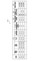
- FIG. 5 is a diagram showing recorded data of candidates narrowed down from the occurrence recovery warning pattern DB 15.
- the table 250 shown in FIG. 5 includes items of serial number, [1], [2], [3], and [4]. Specific data is recorded in each candidate entry No. 1, entry No. 2, and entry No. 3.
- Item [1] includes basic information and statistical information regarding repeated warnings of past cases.
- the basic information regarding the repeated alarm includes information on the content of the alarm and information on the location where the alarm occurred.
- the statistical information for item [1] includes items [1-1], [1-2], and [1-3].
- Item [1-1] indicates the average value of the alarm occurrence interval. The average value of the alarm generation interval is calculated by the above-mentioned formula (1).
- Item [1-2] indicates the standard deviation of the alarm occurrence interval. The standard deviation of the alarm occurrence interval is calculated by the above-mentioned formula (2).
- Item [1-3] indicates the percentage of abnormality duration in repeated alarms. The ratio of the abnormality duration time in the repeated alarm is calculated by the above-mentioned formula (3).
- Item [2] indicates the range of similarity coefficients used for determining similarity.
- the range of the similarity coefficient for the entry No. 1 candidate is "0.9 to 1.1".
- the range of similarity coefficients for candidates for entries No. 2 and No. 3 is "0.8 to 1.2", respectively.
- Item [3] indicates whether or not the alarm has repeatedly spread to other devices as a ripple event.
- the entry No. 1 candidate there were no repeated warnings spread to other devices.
- the entry No. 2 candidate the alarm was actually repeatedly transmitted to the entry No. 3 device.
- the entry No. 3 candidate the alarm was actually repeatedly transmitted to the entry No. 2 device.
- Item [4] indicates the cause of the abnormality regarding repeated alarms in past cases.
- the cause of the abnormality regarding the entry No. 1 candidate is a failure of the wavelength selective switch (WSS).
- WSS wavelength selective switch
- the cause of the abnormality in candidates for entries No. 2 and No. 3 is a failure of the optical amplification unit (AMP).
- the alarm pattern matching unit 16 performs pattern matching of repeated warnings using, as an example, criteria from the following three viewpoints regarding the repeating pattern.
- the repeating alarm with the repeating pattern shown in FIG. 3B is not similar to the repeating alarm with the repeating pattern shown in FIG. 3C.
- the period from time t0 to time t2 (first period) shown in FIG. 3B is shorter than the period from time t0 to time t2 (first period) shown in FIG. 3C. That is, it can be seen that the repeating alarm having the repeating pattern shown in FIG. 3B has a shorter period than the repeating alarm having the repeating pattern shown in FIG. 3C, and the similarity between the two is lower. Therefore, from the first viewpoint, the alarm pattern matching unit 16 determines the similarity based on the average value of the alarm generation intervals shown in FIG. 5 [1-1].
- the repeating alarm with the repeating pattern shown in FIG. 3D is not similar to the repeating alarm with the repeating pattern shown in FIG. 3E.
- the period from time t0 to time t2 (first cycle) shown in FIG. 3D is not much different from the period from time t2 to time t4 (second cycle).
- the period from time t0 to time t2 (first cycle) shown in FIG. 3E is longer than the period from time t2 to time t4 (second cycle).
- the alarm pattern matching unit 16 determines the similarity based on item [1-2] standard deviation of alarm generation intervals (variation in time intervals) shown in FIG.
- the repeated alarm having the repeating pattern shown in FIG. 3F is characterized in that the abnormality duration is longer than the recovery duration. Focusing on the period from time t0 to time t2 (first cycle) shown in Figure 3F, the abnormality duration from time t0 to time t1 is about twice as long as the recovery duration from time t1 to time t2. It is. Further, this repeated warning has a similar tendency in the second period and the third period. In other words, it can be seen that the repeating alarm having the repeating pattern shown in FIG. 3F has a large ratio of the abnormality duration to the cycle. Therefore, from a third viewpoint, the alarm pattern matching unit 16 determines the similarity based on the ratio of abnormality duration in repeated alarms shown in FIG. 5 [1-3].
- the alarm pattern matching unit 16 requires less calculation compared to conventional technology, determines similarity without imposing a processing load on the CPU, and determines whether or not it matches a typical failure case. Can be detected quickly. Note that it is also possible to utilize AI technology such as machine learning to determine similarity.
- the alarm pattern matching unit 16 has a function of executing a notification process to the host device 30 etc. in conjunction with the similarity determination process. These functions will be described later together with the processing operations of the alarm pattern matching section 16.
- the network equipment monitoring device 10 is realized, for example, by a computer 900 having a configuration as shown in FIG.
- FIG. 6 is a hardware configuration diagram showing an example of a computer 900 that implements the functions of the network equipment monitoring device 10 according to the present embodiment.
- the computer 900 includes a CPU (Central Processing Unit) 901, a ROM (Read Only Memory) 902, a RAM (Random Access Memory) 903, an HDD (Hard Disk Drive) 904, an input/output I/F (Interface) 905, and a communication I/F 906. and a media I/F 907.
- CPU Central Processing Unit
- ROM Read Only Memory
- RAM Random Access Memory
- HDD Hard Disk Drive
- I/F Interface
- the CPU 901 operates based on a program stored in the ROM 902 or HDD 904.
- the ROM 902 stores a boot program executed by the CPU 901 when the computer 900 is started, programs related to the hardware of the computer 900, and the like.
- the CPU 901 controls an input device 910 such as a mouse and a keyboard, and an output device 911 such as a display and a printer via an input/output I/F 905.
- the CPU 901 obtains data from the input device 910 via the input/output I/F 905 and outputs the generated data to the output device 911.
- a GPU Graphics Processing Unit
- the like may be used in addition to the CPU 901 as the processor.
- the HDD 904 stores programs executed by the CPU 901 and data used by the programs.
- Communication I/F 906 receives data from other devices via communication network 920 and outputs it to CPU 901 , and also transmits data generated by CPU 901 to other devices via communication network 920 .
- the media I/F 907 reads the program or data stored in the recording medium 912 and outputs it to the CPU 901 via the RAM 903.
- the CPU 901 loads a program related to target processing from the recording medium 912 onto the RAM 903 via the media I/F 907, and executes the loaded program.
- the recording medium 912 is an optical recording medium such as a DVD (Digital Versatile Disc) or a PD (Phase change rewritable disk), a magneto-optical recording medium such as an MO (Magneto Optical disk), a magnetic recording medium, a semiconductor memory, or the like.
- the CPU 901 realizes the functions of the network equipment monitoring device 10 by executing a program loaded onto the RAM 903. Furthermore, the data in the RAM 903 is stored in the HDD 904 .
- the CPU 901 reads a program related to target processing from the recording medium 912 and executes it. In addition, the CPU 901 may read a program related to target processing from another device via the communication network 920.
- the alarm reaping unit 12 starts and executes reaping processing and transmission processing (step S10).
- an abnormality detection alarm and a recovery detection alarm are repeated for the same alarm content of the network equipment NE1, and each alarm is stored in the alarm DB 11.
- the alarm reaping unit 12 performs the alarm reaping process, the corresponding alarm is deleted from the alarm DB 11.
- the repeated alarm extraction unit 14 determines that the alarm group from time t0 to time t6, for example, satisfies the condition.
- the repeated alarm extraction unit 14 extracts a repeated alarm that is a group of alarms from time t0 to time t6 (step S20). Then, the repeated alarm extraction section 14 passes the extracted repeated alarm to the alarm pattern matching section 16 (step S30).
- the alarm pattern comparison unit 16 executes similar pattern detection processing by comparing the received repeated alarm with the repeated alarms of past cases recorded in the occurrence recovery alarm pattern DB 15 (step S40). Details of this processing will be described later. If it is determined that the similarity is high, the alarm pattern matching unit 16 notifies the host device 30 of the cause of the repeated alarm in the past case (step S50). Further, the alarm pattern matching section 16 instructs the alarm reaping section 12 to stop the reaping process (step S60).
- the content of the mowing stop instruction is, for example, to stop mowing for abnormality detection alarms and recovery detection alarms that have entries of "device name: OXC-01", "occurrence location: 10G path CH03", and alarm content "LOS". It is something.
- the alarm reaping unit 12 stops the alarm reaping process and the alarm transmission process (step S70). Note that when the warning pattern matching unit 16 determines that the similarity between the received repeated warning and the repeated warning of the past case is low, it does not execute step S50 and step S60.
- the network equipment NE1 Even after the mowing is stopped, the network equipment NE1 continues to output abnormality detection alarms and recovery detection alarms for a while, but the alarms are stopped for a predetermined period after time t31, for example. At this time, the alarm from the network equipment NE1 is not accumulated in the alarm DB 11 for a predetermined period of time. Thereby, the repeated alarm extraction unit 14 detects the restoration of the network equipment NE1 (step S80). Then, the repeated alarm extraction unit 14 instructs the alarm reaping unit 12 to release the reaping stop state (step S90).
- the content of the mowing stop cancellation instruction is, for example, to cancel the mowing stop for abnormality detection alarms and recovery detection alarms that have entries of "device name: OXC-01", "occurrence location: 10G path CH03", and alarm content "LOS”. .
- the alarm reaping unit 12 restarts and executes an alarm reaping process and a transmission process (step S100).
- the alarm pattern matching section 16 may repeatedly notify the alarm extraction section 14 that the alarm reaping section 12 has been instructed to stop the reaping process. Thereby, it is possible to reliably prevent a malfunction in which the alarm extractor 14 repeatedly issues an instruction to cancel when the alarm reaping section 12 is not in the mowing stopped state.
- the alarm pattern matching unit 16 does not necessarily execute all the processes described in FIG. 8 every time.
- the alarm pattern collation unit 16 acquires the repeated alarm information 320 (FIG. 4B) from the repeated alarm extraction unit 14, it narrows down past case candidates (step S41).
- the warning pattern matching unit 16 creates a table 250 (FIG. 5) that stores recorded data of each past case candidate to be matched with the repeated warning information 320.
- the warning pattern matching unit 16 executes a similarity determination process (step S42) between the repeated warning information 320 and each candidate to be matched.
- the alarm pattern matching unit 16 calculates the characteristic information of the repeated alarm from the time information 326 of the repeated alarm information 320 (FIG. 4B), as shown in FIG. 9A (step S42). S421). Here, the alarm pattern matching unit 16 calculates each statistical information as the characteristic information of the repeated alarm in question using the above-mentioned equations (1) to (3).
- the alarm pattern matching unit 16 calculates the range of past case characteristic information for each past case candidate (step S422).
- the alarm pattern matching unit 16 calculates the range of the characteristic information of the past case using the statistical information of item [1] and the range of similarity coefficient of item [2] in the table 250 (FIG. 5). do. Specifically, in the case of entry No. 1 shown in FIG. 5, the range of the similarity coefficient is set to "0.9 to 1.1", and the average value of the alarm generation interval is "1.0 sec". In this case, the range of feature information (threshold range) of past cases is "0.9 to 1.1 seconds". At this time, if the average value of the occurrence interval calculated from the repeated alarm in question is within the range of "0.9 to 1.1 seconds", it will be determined that the similarity to the past case is high.
- the alarm pattern matching unit 16 detects past cases that have a high degree of similarity to the repeated alarm in question (step S423).
- the alarm pattern matching unit 16 sequentially performs a similarity determination process between the repeated alarm information 320 shown in FIG. 4B and each candidate to be matched (No. 1, No. 2, No. 3 shown in FIG. 5). Let's do it.
- the warning pattern matching unit 16 determines that the similarity is high in all of the above-mentioned first to third viewpoints, the repeated warning extracted from the warning DB 11 is highly similar to the past case. , it is determined. If there is no candidate that can be determined to have high similarity from all viewpoints, the alarm pattern matching unit 16 ends the process.
- the alarm pattern matching unit 16 determines whether there is a ripple effect (step S43: FIG. 8). That is, the alarm pattern matching unit 16 determines whether a ripple event is registered in a past case with high similarity. For example, if the past case with high similarity is entry No. 1 shown in FIG. The cause "WSS failure" is notified to the host device 30 (step S50).
- Step S44 A predetermined standby period (for example, 120 seconds) is set in the standby mode process (step S44). During this standby period, the alarm pattern collation unit 16 determines whether a new repeated alarm has been received from the repeated alarm extraction unit 14, as shown in FIG. 9B (step S441). If a new repeat warning has not been received (step S441: No), the warning pattern matching unit 16 determines whether the standby period has ended (step S442). If the standby period has ended (step S442: Yes), the alarm pattern matching unit 16 ends the process.
- step S44 the alarm pattern matching unit 16 ends the process.
- step S442 determines whether the standby period has not ended in step S442 (step S442: No). If a new repeated warning is received during the standby period (step S441: Yes), the alarm pattern matching unit 16 executes similarity determination processing (step S443) and ends the standby mode processing.
- the similarity determination process in step S443 is similar to the similarity determination process in step S42 (FIG. 9A).
- the alarm pattern matching unit 16 similarly determines similarity using all of the first to third viewpoints described above.
- the past case candidate is information on repeated warnings (for example, information on entry No. 3) that has been accumulated as a ripple event of the past case.
- the repeated alarm in question is a new repeated alarm that occurred during the standby period.
- step S443 If it is determined in step S443 that the similarity between the new repeated warning and the repeated warning of the past influence case is low, the warning pattern matching unit 16 ends the process. On the other hand, if it is determined in step S443 that the new repeated warning is highly similar to the repeated warning in the past ripple case, in step S50 the warning pattern matching unit 16 determines that the abnormality in the past case of entry No. 2 is The host device 30 is notified of the cause of "AMP failure".
- the warning pattern matching unit 16 sends the warning reaping unit 12 a process of reaping repeated warnings that have been determined to have a high degree of similarity to past cases. Instructs to stop each transmission process (step S60). After notifying the cause of the repeated alarm, the alarm harvesting unit 12 does not need to notify the host device 30 of the repeated alarm. By stopping the warning harvesting unit 12 from repeatedly notifying the host device 30 of warnings, the system load can be reduced.
- FIG. 10 is a schematic diagram showing the operation of a conventional network equipment monitoring device to notify an abnormality detection alarm and a recovery detection alarm.
- a conventional network equipment monitoring device 110 accumulates alarm data notified from the network equipment 20 in an alarm DB 11.
- the alarm harvesting unit 12 periodically harvests alarms from the alarm DB 11 and transmits them to the host device 30 .
- the conventional network equipment monitoring device 110 when an abnormality detection alarm and a recovery detection alarm repeatedly occur for the same alarm content of the network equipment NE1, for example, a large amount of data is sent from the network equipment monitoring device 110 to the host device 30. An alert will be notified. As a result, the host device 30 displays a large number of warnings, increasing the amount of confirmation work required by maintenance personnel. Therefore, it takes the maintenance person time to identify the cause of the abnormality in the network equipment NE1. Further, when abnormality detection alarms and recovery detection alarms are repeatedly generated, the processing load on the alarm reaping section 12 for reaping a large amount of warnings from the alarm DB 11 increases. This may cause problems such as a delay in the warning from the alarm harvester 12 to the host device 30, or a leak of an alarm that should be sent from the alarm harvester 12 to the host device 30.
- the repeated pattern of repeated warnings based on past cases and the cause of the abnormality are registered in the occurrence/recovery warning pattern DB 15. Furthermore, when an abnormality detection alarm and a recovery detection alarm occur repeatedly, the repeated alarm extraction section 14 extracts the repeated alarm and passes it to the alarm pattern matching section 16. Then, the alarm pattern matching unit 16 determines the similarity with the repeating pattern in past failure cases, and notifies the maintenance person of the cause of the abnormality for the past cases determined to be highly similar. Furthermore, after detecting a past case with high similarity, the network equipment monitoring device 10 reduces the system load by stopping repeated warning harvesting processing and stopping notification of warnings to the host device 30.
- the network equipment monitoring device 10 when a failure occurs due to the main signal in the optical transmission system 1, it is possible for a maintenance person to easily identify the failure location, and at the same time, it is possible to suppress the output of a large amount of alarms. Can be done.
- the network equipment monitoring device includes an alarm database 11 that stores, as alarm information, abnormality detection alarms that notify the occurrence of an abnormality and recovery detection alarms that notify the recovery from the abnormality that are output from the network equipment 20 of the optical transmission system 1. , an alarm reaping unit 12 that periodically harvests the alarm information accumulated in the alarm database 11 and sends it to a predetermined notification destination (upper-level device 30); A repeated alarm extraction unit 14 extracts a group of alarms in which abnormality detection alarms and recovery detection alarms are repeatedly generated a predetermined number of times within a time as repeated alarms, and information on repeated alarms of past cases is accumulated together with the cause of the repeated alarms.
- the occurrence recovery warning pattern database 15 and the extracted repeated warning information are compared with the past case's repeated warning information, and if it is determined that the similarity is higher than a predetermined threshold, the cause of the past case's repeated warning is determined. It is characterized by comprising an alarm pattern matching unit 16 that notifies a predetermined notification destination (upper device 30).
- the alarm pattern matching unit 16 can detect whether past cases with a similarity higher than a predetermined threshold have been accumulated in response to repeated alarms that notify the occurrence of an abnormality and recovery from the abnormality. If so, it is possible to notify the cause of repeated warnings in the past. Therefore, the maintainer of the network equipment can quickly identify the cause of the repeated alarm.
- information on repeated warnings in past cases includes warning content information, identification information of the network equipment 20 where the warning occurred, and information recorded in association with time information of the abnormality detection alarm or recovery detection alarm, respectively.
- the alarm pattern matching unit 16 includes basic information including information specifying the location where the alarm occurred, and statistical information calculated using time information as characteristic information of the repeating pattern. The method is characterized in that statistical information is calculated as characteristic information of a repeating pattern using time information, and the similarity is determined by comparing it with statistical information about repeating warnings of past cases.
- the occurrence/recovery alarm pattern database 15 can accumulate detailed information of the abnormality detection alarm or recovery detection alarm itself and statistical information calculated using time information. I can do it. Furthermore, the alarm pattern matching unit 16 determines the similarity between the extracted repeated warning and the repeated warning of past cases by comparing the statistical information, so that the processing load of calculation can be reduced.
- the information on the repeated warning of the past case includes information indicating whether or not the repeated warning has spread from the network equipment 20 where the repeated warning of the past case has occurred to other network equipment 20, and information indicating whether the repeated warning has spread to other network equipment 20.
- the alarm pattern matching unit 16 includes identification information of other network equipment 20 that has experienced the occurrence of the alarm, and characteristic information of the repeating pattern of the repeated alarm that occurred as a ripple event. If information has been accumulated indicating that there has been a ripple effect regarding repeated warnings from past cases that were determined to be higher than the threshold, the system will wait for a predetermined period of time, and a new repeated warning will occur within the predetermined period. In this case, the new repeated warning information is compared with the repeated warning information accumulated as a ripple event of past cases to determine the similarity.
- the alarm pattern matching unit 16 detects that there has been a ripple effect regarding the repeated alarm of the past case that has been determined to have a similarity with the extracted repeated alarm that is higher than a predetermined threshold. If information indicating the above has been accumulated, it can be determined whether the extracted repeated alarm will spread to other network equipment. Therefore, when a plurality of network equipment repeatedly output warnings indicating an abnormality regarding one cause, a maintainer of the network equipment can quickly identify the cause of the repeated warning.
- the alarm pattern matching unit 16 determines that the similarity between the extracted repeated alarm information and the repeated alarm information of past cases is higher than a predetermined threshold, the alarm pattern matching unit 16 On the other hand, it is characterized in that it instructs to stop each of the process of reaping and the process of transmitting repeated warnings that have been determined to have a high degree of similarity.
- the alarm reaping unit 12 In the network equipment monitoring device, if the repeated alarm extraction unit 14 cannot extract the repeated alarm from the alarm database 11 within a predetermined period after the reaping of the repeated alarm has stopped, the alarm reaping unit 12 The invention is characterized in that it instructs the user to cancel the stopped state of reaping for the repeated warning.
- the repeated alarm extracting unit 14 detects that the network equipment that was outputting the repeated alarm has been restored, it immediately generates the next repeated alarm and the repeated alarm of the past case. can be compared with
- the network equipment monitoring method is a network equipment monitoring method for the network equipment monitoring device 10, in which the network equipment monitoring device 10 receives an abnormality detection alarm output from the network equipment 20 of the optical transmission system 1 to notify of the occurrence of an abnormality and recovery from the abnormality.
- the system is equipped with an alarm database 11 that stores recovery detection alarms that notify the user of the occurrence of the alarm as alarm information, and an occurrence recovery alarm pattern database 15 that accumulates information on repeated alarms from past cases together with the causes of the repeated alarms, which are stored in the alarm database 11.
- the network equipment monitoring device 10 accumulates past cases in which the similarity is higher than a predetermined threshold in response to repeated warnings notifying occurrence of an abnormality and recovery from the abnormality. If so, it is possible to notify the cause of repeated warnings in the past. Therefore, the maintainer of the network equipment can quickly identify the cause of the repeated alarm.
- the present invention is not limited to the embodiments described above, and many modifications can be made within the technical idea of the present invention by those having ordinary knowledge in this field.
- the alarm pattern matching unit is supposed to notify the host device 30 of the cause of past cases of repeated alarms, the present invention is not limited to this, and the GUI unit 13 may also be notified.
- the alarm pattern matching section may notify the host device 30 and the GUI section 13 of the cause of past cases of repeated alarms. Further, the alarm pattern matching section may notify only the host device 30 or only the GUI section 13 of the cause, depending on the cause of past cases of repeated alarms.
- the average value of the alarm generation interval, the standard deviation of the alarm generation interval, and the ratio of the abnormality duration time in the repeated alarm are exemplified as the characteristic information of the repetition pattern, but the information is not limited to these.
- the characteristic information may be statistical information that can be calculated using time information of repeated warnings. This network equipment monitoring method can easily add statistical information determined by other available calculation methods.
- the alarm pattern matching unit determines that the past case is highly similar to the repeated alarm in question when the similarity is high in all three aspects regarding the feature information, but the present invention is not limited to this.
- the number of viewpoints regarding feature information necessary to determine similarity is determined in advance.
- the content of the alarm is not limited to LOS, but may be other failure states such as loss of frame (LOF).
Landscapes
- Engineering & Computer Science (AREA)
- Computer Networks & Wireless Communication (AREA)
- Signal Processing (AREA)
- Data Exchanges In Wide-Area Networks (AREA)
- Physics & Mathematics (AREA)
- Electromagnetism (AREA)
Abstract
Description
[システム構成の概要]
図1に示すように、光伝送システム1は、ネットワーク設備監視装置10と、ネットワーク設備20と、上位装置30と、を備えている。
ネットワーク設備監視装置10は、例えば、NE-OpS(Network element operation system)で構成され、ネットワーク設備20から取得した警報を上位装置30に通知すると共に、必要に応じて、過去事例の異常の原因を上位装置30に通知する。上位装置30は、ネットワーク設備監視装置10を監視する装置であり、警報等を保守者2に提示する。
ネットワーク設備監視装置10は、警報データベース11と、警報刈り取り部12と、GUI(Graphical User Interface)部13と、繰り返し警報抽出部14と、発生回復警報パターンデータベース15と、警報パターン照合部16と、を備えている。これらの各部は、ネットワーク設備監視装置という同じ筐体に収容してもよいし、互いに異なる筐体に収容してもよい。なお、以下の記載および図面では、データベースをDBと表記する。
過去事例の繰り返し警報の情報は、基本情報と、過去事例の繰り返し警報についての異常の原因と、統計情報と、を含む。基本情報は、警報内容情報、警報が発生したネットワーク設備の識別情報、および警報が発生した個所を特定する情報を、含む。これらの情報は、異常検知警報または回復検知警報の時刻情報に対応付けてそれぞれ記録される。
図2は、発生回復警報パターンDB15に登録される基本情報となる過去の発生回復繰り返し警報の例を示す図である。図2に示す基本情報210は、項目211~215に関する情報を含んでいる。項目211は、警報が発生した日時を示す。日時は、例えば年月日や時分秒で表される。項目212は、警報の種別を示す。この例では、「発生」は異常検知警報を表し、「回復」は、回復検知警報を表している。なお、項目211において、時刻t0は、この繰り返し警報における最初の異常検知警報が発生した日時を示す。また、時刻t1は、この繰り返し警報における最初の回復検知警報が発生した日時を示す。項目213は、警報内容を示す。LOSは、信号消失(Loss of Signal)を表す。項目214は、警報を出力した装置名を示す。OXCは、光クロスコネクト(optical cross-connect)を表す。項目215は、警報の発生個所を示す。10GパスCH03は、10 Giga bits per second path channel 03を表す。なお、基本情報210の各項目の値は一例である。
過去事例の繰り返し警報についての異常の原因は、例えば波長選択スイッチ(WSS)22の故障や、光増幅部(AMP)23の故障等である。異常を知らせる警報と復旧を知らせる警報の繰り返しパターンは、装置の故障個所により様々なパターンがあり、異常の原因を特定することが困難である。警報内容が「LOS」を示すものであっても、異常の原因は、波長選択スイッチ(WSS)の故障なのか、光増幅部(AMP)の故障なのか、原因を特定することは難しい。
また、光増幅部(AMP)の出力に揺らぎがある場合、所定のネットワーク設備20において、LOS、回復、LOS、回復、…の警報が繰り返される事象が発生し、別のネットワーク設備20でもLOS、回復、LOS、回復、…の警報が繰り返される。つまり、繰り返し警報が他の装置にも波及することがある。波及は、例えば光増幅部の故障という1つの原因に対して、複数個所からの異常に関する繰り返し警報が発生するという事象である。
発生回復警報パターンDB15に登録される統計情報は、過去事例の繰り返し警報について、繰り返しパターンの特徴情報として時刻情報を用いて算出された情報である。ここで、繰り返しパターンについて図3Aを参照して説明する。図3Aは、繰り返し警報の時間変化を示すグラフである。横軸は時間軸であり、繰り返し警報の時刻情報を示す。縦軸は警報の種別を2値化して示す。異常検知警報は1で表され、回復検知警報は0で表される。図3B~図3Fは、他の繰り返しパターンを示す図である。これらの繰り返しパターンについての詳細は後記する。
具体的には、図3Aにおいて、時刻t0から時刻t1までの期間T1は、第1の異常継続期間である。時刻t1から時刻t2までの期間T2は、第1の回復継続期間である。時刻t2から時刻t3までの期間T3は、第2の異常継続期間である。時刻t3から時刻t4までの期間T4は、第2の回復継続期間である。時刻t4から時刻t5までの期間T5は、第3の異常継続期間である。時刻t5から時刻t6までの期間T6は、第3の回復継続期間である。時刻t6から時刻t7までの期間T7は、第4の異常継続期間である。
また、期間T1と期間T2の和は、第1の周期である。期間T3と期間T4の和は、第2の周期である。期間T4と期間T5の和は、第3の周期である。なお、周期は一定とは限らない。
繰り返しパターンの特徴情報は、例えば、警報発生間隔の平均値、警報発生間隔の標準偏差、繰り返し警報における異常継続時間の割合等である。
警報発生間隔の平均値は、異常検知警報の出力時刻と、回復検知警報の出力時刻と、の間隔の平均値である。図3Aに示す時刻t7までの繰り返しパターンの場合、警報発生間隔の平均値は、異常継続期間T1, T3, T5, T7および回復継続期間T2, T4, T6の平均値である。時刻t0から時刻tnまでの時刻情報を用いる場合、警報発生間隔の平均値は、次の式(1)によって算出される。



発生回復警報パターンDB15に登録される情報には、さらに、類似性の基準値(統計情報)からの許容範囲に対応して予め設定された類似度係数の範囲を含むことができる。類似度係数の範囲は、比較しようとする繰り返し警報の統計情報と過去事例の統計情報とが同一(100%)である場合を基準として含む範囲である。類似度係数の範囲は、下限値と上限値で定められる。過去事例の統計情報の値と類似度係数の下限値とを乗算した計算結果は、類似性が高いと判定するための閾値(下限値)となる。過去事例の統計情報の値と類似度係数の上限値とを乗算した計算結果は、類似性が高いと判定するための閾値(上限値)となる。なお、警報パターン照合部16は、前記抽出された繰り返し警報の時刻情報を用いて繰り返しパターンの特徴情報として統計情報を算出し、過去事例の繰り返し警報についての統計情報と照合して類似性を判定する。
発生回復警報パターンDB15に登録される情報には、さらに、波及事象を含むことができる。すなわち、過去事例の繰り返し警報の情報には、さらに、過去事例の繰り返し警報が発生したネットワーク設備20から他のネットワーク設備20への繰り返し警報の波及があったか否を示す情報を含むことができる。繰り返し警報の波及があった場合、繰り返し警報の波及があった他のネットワーク設備20の識別情報と、波及事象として発生した繰り返し警報の繰り返しパターンの特徴情報と、を含む。
繰り返し警報抽出部14は、定期的に警報DB11から繰り返し警報を検索する。ここで、繰り返し警報の抽出条件として、警報の繰り返し時間や繰り返し回数は、事前に定義される。警報の繰り返し時間は短時間であることが好ましく、例えば60秒としてもよい。同一のネットワーク設備から出力される同一の警報内容は、例えば、「10GパスCH03におけるLOS」としてもよい。いずれかの警報の回数は、例えば、5回、7回、または10回としてもよい。繰り返し警報抽出部14は、検索により抽出条件を満たす警報群を見つけた場合、予め定められた回数(例えば5回)以上記録されている警報群を1つの繰り返し警報として抽出し、警報パターン照合部16へ渡す。
警報パターン照合部16は、図4Bに示す繰り返し警報の情報320を繰り返し警報抽出部14から取得すると、類似性の判定処理を開始する。警報パターン照合部16は、発生回復警報パターンDB15に予め蓄積された過去事例の中から、繰り返し警報の情報320と照合すべき候補を絞り込む。警報パターン照合部16は、繰り返し警報の情報320に記載された警報内容323の情報に基づいて、その警報内容が記載された過去事例を、照合すべき候補の記録データとして抽出する。
項目〔1〕は、過去事例の繰り返し警報についての基本情報と、統計情報とを含んでいる。繰り返し警報についての基本情報は、警報内容の情報、および発生個所の情報を含んでいる。
図3Bに示す繰り返しパターンを有する繰り返し警報は、図3Cに示す繰り返しパターンを有する繰り返し警報とは類似していない。図3Bに示す時刻t0から時刻t2までの期間(第1の周期)は、図3Cに示す時刻t0から時刻t2までの期間(第1の周期)よりも短い。つまり、図3Bに示す繰り返しパターンを有する繰り返し警報は、図3Cに示す繰り返しパターンを有する繰り返し警報よりも周期が短く、両者の類似性が低いことが分かる。そこで、警報パターン照合部16は、第1の観点では、図5に示す項目〔1-1〕 警報発生間隔の平均値を基準にして類似性を判定する。
図3Dに示す繰り返しパターンを有する繰り返し警報は、図3Eに示す繰り返しパターンを有する繰り返し警報とは類似していない。図3Dに示す時刻t0から時刻t2までの期間(第1の周期)は、時刻t2から時刻t4までの期間(第2の周期)とあまり変わらない。図3Eに示す時刻t0から時刻t2までの期間(第1の周期)は、時刻t2から時刻t4までの期間(第2の周期)よりも長い。つまり、図3Eに示す繰り返しパターンを有する繰り返し警報は、図3Dに示す繰り返しパターンを有する繰り返し警報よりも周期の変動量が多く、両者の類似性が低いことが分かる。そこで、警報パターン照合部16は、第2の観点では、図5に示す項目〔1-2〕 警報発生間隔の標準偏差(時間間隔のばらつき)を基準にして類似性を判定する。
図3Fに示す繰り返しパターンを有する繰り返し警報は、回復継続期間に比べて異常継続期間が長い、という特徴を有している。図3Fに示す時刻t0から時刻t2までの期間(第1の周期)に注目すると、時刻t0から時刻t1までの異常継続期間は、時刻t1から時刻t2までの回復継続期間の2倍ほどの長さである。また、この繰り返し警報は、第2の周期や第3の周期においても同様の傾向を有している。つまり、図3Fに示す繰り返しパターンを有する繰り返し警報は、周期に対する異常継続期間の割合が大きい、ことが分かる。そこで、警報パターン照合部16は、第3の観点では、図5に示す項目〔1-3〕 繰り返し警報における異常継続時間の割合を基準にして類似性を判定する。
警報パターン照合部16は、類似性の判定処理に付随して、上位装置30等への通知処理を実行する機能等を有する。これらの機能については、警報パターン照合部16の処理動作と併せて後記する。
前記実施形態に係るネットワーク設備監視装置10は、例えば図6に示すような構成のコンピュータ900によって実現される。
図6は、本実施形態に係るネットワーク設備監視装置10の機能を実現するコンピュータ900の一例を示すハードウェア構成図である。コンピュータ900は、CPU(Central Processing Unit)901、ROM(Read Only Memory)902、RAM(Random Access Memory)903、HDD(Hard Disk Drive)904、入出力I/F(Interface)905、通信I/F906およびメディアI/F907を有する。
次に、ネットワーク設備監視装置10による監視処理の流れについて図7を参照(適宜図1参照)して説明する。
ネットワーク設備監視装置10において、警報刈り取り部12は、始動して刈取処理と送信処理とを実行する(ステップS10)。ここでは、例えばネットワーク設備NE1の同一の警報内容について異常検知警報および回復検知警報が繰り返しており、それぞれの警報が警報DB11に蓄積されるものとする。警報刈り取り部12が警報の刈取処理を行うと、警報DB11から該当の警報が削除される。定期的な刈取処理が行われていないときに、繰り返し警報抽出部14は、例えば時刻t0~時刻t6の警報群が条件を満たすと判定する。この場合、繰り返し警報抽出部14は、時刻t0~時刻t6の警報群をまとめた繰り返し警報を抽出する(ステップS20)。そして、繰り返し警報抽出部14は、抽出した繰り返し警報を警報パターン照合部16に受け渡す(ステップS30)。
まず、警報パターン照合部16は、繰り返し警報抽出部14から、繰り返し警報の情報320(図4B)を取得すると、過去事例の候補を絞り込む(ステップS41)。このとき、警報パターン照合部16は、繰り返し警報の情報320と照合すべき過去事例の各候補の記録データを格納したテーブル250(図5)を作成する。そして、警報パターン照合部16は、繰り返し警報の情報320と照合すべき各候補との類似度判定処理(ステップS42)を実行する。
例えば、類似性が高い過去事例が、図5に示すエントリNo.1であった場合、波及事象が登録されていないので、警報パターン照合部16は、エントリNo.1の過去事例の繰り返し警報の原因「WSS故障」を上位装置30に通知する(ステップS50)。
一方、ステップS443において、新たな繰り返し警報と、過去の波及事例の繰り返し警報との類似性が高いと判定した場合、ステップS50において、警報パターン照合部16は、エントリNo.2の過去事例の異常の原因「AMP故障」を上位装置30に通知する。
また、異常検知警報および回復検知警報が繰り返し発生するとき、警報刈り取り部12は、警報DB11から大量の警報を刈り取る処理の負荷が増大する。これによって、警報刈り取り部12から上位装置30への警報が遅延したり、警報刈り取り部12から上位装置30へ通知すべき警報が漏れたりする等の不具合が生じる可能性があった。
以上説明したように、ネットワーク設備監視装置は、光伝送システム1のネットワーク設備20から出力される異常発生を知らせる異常検知警報および異常の回復を知らせる回復検知警報を警報情報として蓄積する警報データベース11と、警報データベース11に蓄積された警報情報を定期的に刈り取って所定の通知先(上位装置30)へ送信する警報刈り取り部12と、警報データベース11から、同一のネットワーク設備の同一の警報内容について所定時間内に異常検知警報および回復検知警報が所定回数繰り返して発生している警報群を繰り返し警報として抽出する繰り返し警報抽出部14と、過去事例の繰り返し警報の情報を当該繰り返し警報の原因と共に蓄積した発生回復警報パターンデータベース15と、抽出された繰り返し警報の情報を、過去事例の繰り返し警報の情報と照合し、類似性が所定の閾値よりも高いと判定した場合、過去事例の繰り返し警報の原因を所定の通知先(上位装置30)に通知する警報パターン照合部16と、を備えることを特徴とする。
例えば、警報パターン照合部は、繰り返し警報の過去事例の原因を上位装置30へ通知するものとしたが、これに限らず、GUI部13へ通知するようにしてもよい。また、警報パターン照合部は、繰り返し警報の過去事例の原因を上位装置30およびGUI部13へ通知するようにしてもよい。さらに、警報パターン照合部は、繰り返し警報の過去事例の原因に応じて、原因を上位装置30のみに通知したり、GUI部13のみに通知したりしてもよい。
また、警報パターン照合部は、特徴情報に関する3つの観点すべてで類似性が高い場合に、問題となっている繰り返し警報との類似性が高い過去事例であると判定したが、これに限らない。類似性を判定するために必要な特徴情報に関する観点の個数は予め定められる。
警報内容はLOSに限らず、例えばフレーム同期外れ(Loss of Frame:LOF)等の他の障害状態であってもよい。
2 保守者
10 ネットワーク設備監視装置
11 警報データベース
12 警報刈り取り部
13 GUI部(通知先)
14 繰り返し警報抽出部
15 発生回復警報パターンデータベース
16 警報パターン照合部
20 ネットワーク設備
21 トランスポンダ
22 波長選択スイッチ
23 光増幅部
30 上位装置(通知先)
Claims (7)
- 光伝送システムのネットワーク設備から出力される異常発生を知らせる異常検知警報および異常の回復を知らせる回復検知警報を警報情報として蓄積する警報データベースと、
前記警報データベースに蓄積された警報情報を定期的に刈り取って所定の通知先へ送信する警報刈り取り部と、
前記警報データベースから、同一のネットワーク設備の同一の警報内容について所定時間内に異常検知警報および回復検知警報が所定回数繰り返して発生している警報群を繰り返し警報として抽出する繰り返し警報抽出部と、
過去事例の繰り返し警報の情報を当該繰り返し警報の原因と共に蓄積した発生回復警報パターンデータベースと、
前記抽出された繰り返し警報の情報を、前記過去事例の繰り返し警報の情報と照合し、類似性が所定の閾値よりも高いと判定した場合、前記過去事例の繰り返し警報の原因を前記所定の通知先に通知する警報パターン照合部と、を備えることを特徴とするネットワーク設備監視装置。 - 前記過去事例の繰り返し警報の情報は、
異常検知警報または回復検知警報の時刻情報に対応付けてそれぞれ記録された、警報内容情報、警報が発生したネットワーク設備の識別情報、および警報が発生した個所を特定する情報を、含む基本情報と、
繰り返しパターンの特徴情報として前記時刻情報を用いて算出された統計情報と、を含み、
前記警報パターン照合部は、前記抽出された繰り返し警報の時刻情報を用いて繰り返しパターンの特徴情報として統計情報を算出し、前記過去事例の繰り返し警報についての統計情報と照合して類似性を判定することを特徴とする請求項1に記載のネットワーク設備監視装置。 - 前記過去事例の繰り返し警報の情報は、
過去事例の繰り返し警報が発生したネットワーク設備から他のネットワーク設備への繰り返し警報の波及があったか否を示す情報と、
繰り返し警報の波及があった他のネットワーク設備の識別情報と、波及事象として発生した繰り返し警報の繰り返しパターンの特徴情報と、を含み、
前記警報パターン照合部は、前記抽出された繰り返し警報との類似性が所定の閾値よりも高いと判定した過去事例の繰り返し警報について波及があったことを示す情報が蓄積されていた場合、予め定められた期間だけ待機し、前記予め定められた期間に新たな繰り返し警報が発生した場合、前記新たな繰り返し警報の情報を前記過去事例の波及事象として蓄積されている繰り返し警報の情報と照合して類似性を判定することを特徴とする請求項2に記載のネットワーク設備監視装置。 - 前記警報パターン照合部は、前記抽出された繰り返し警報の情報と、前記過去事例の繰り返し警報の情報との類似性が所定の閾値よりも高いと判定した場合、前記警報刈り取り部に対して、類似性が高いと判定された繰り返し警報を刈り取る処理および送信処理のそれぞれの停止を指示することを特徴とする請求項1に記載のネットワーク設備監視装置。
- 前記繰り返し警報抽出部は、前記繰り返し警報の刈り取りが停止状態になった後で予め定められた期間内に、当該繰り返し警報が、前記警報データベースから抽出できない場合、前記警報刈り取り部に対して、当該繰り返し警報の刈り取りの停止状態の解除を指示することを特徴とする請求項4に記載のネットワーク設備監視装置。
- ネットワーク設備監視装置のネットワーク設備監視方法であって、
前記ネットワーク設備監視装置は、
光伝送システムのネットワーク設備から出力される異常発生を知らせる異常検知警報および異常の回復を知らせる回復検知警報を警報情報として蓄積する警報データベースと、過去事例の繰り返し警報の情報を当該繰り返し警報の原因と共に蓄積した発生回復警報パターンデータベースと、を備えており、
前記警報データベースに蓄積された警報情報を定期的に刈り取って所定の通知先へ送信するステップと、
前記警報データベースから、同一のネットワーク設備の同一の警報内容について所定時間内に異常検知警報および回復検知警報が所定回数繰り返して発生している警報群を繰り返し警報として抽出するステップと、
前記抽出された繰り返し警報の情報を、前記過去事例の繰り返し警報の情報と照合し、類似性が所定の閾値よりも高いと判定した場合、前記過去事例の繰り返し警報の原因を前記所定の通知先に通知するステップと、
を実行することを特徴とするネットワーク設備監視方法。 - コンピュータを、請求項1から請求項5のいずれか一項に記載のネットワーク設備監視装置として機能させるためのプログラム。
Priority Applications (3)
| Application Number | Priority Date | Filing Date | Title |
|---|---|---|---|
| JP2024520111A JP7694822B2 (ja) | 2022-05-10 | 2022-05-10 | ネットワーク設備監視装置、ネットワーク設備監視方法およびプログラム |
| PCT/JP2022/019777 WO2023218519A1 (ja) | 2022-05-10 | 2022-05-10 | ネットワーク設備監視装置、ネットワーク設備監視方法およびプログラム |
| US18/857,482 US20250274193A1 (en) | 2022-05-10 | 2022-05-10 | Network facilities monitoring device, network facilities monitoring method and program |
Applications Claiming Priority (1)
| Application Number | Priority Date | Filing Date | Title |
|---|---|---|---|
| PCT/JP2022/019777 WO2023218519A1 (ja) | 2022-05-10 | 2022-05-10 | ネットワーク設備監視装置、ネットワーク設備監視方法およびプログラム |
Publications (1)
| Publication Number | Publication Date |
|---|---|
| WO2023218519A1 true WO2023218519A1 (ja) | 2023-11-16 |
Family
ID=88729989
Family Applications (1)
| Application Number | Title | Priority Date | Filing Date |
|---|---|---|---|
| PCT/JP2022/019777 Ceased WO2023218519A1 (ja) | 2022-05-10 | 2022-05-10 | ネットワーク設備監視装置、ネットワーク設備監視方法およびプログラム |
Country Status (3)
| Country | Link |
|---|---|
| US (1) | US20250274193A1 (ja) |
| JP (1) | JP7694822B2 (ja) |
| WO (1) | WO2023218519A1 (ja) |
Citations (4)
| Publication number | Priority date | Publication date | Assignee | Title |
|---|---|---|---|---|
| JP2010147804A (ja) * | 2008-12-18 | 2010-07-01 | Fujitsu Telecom Networks Ltd | 伝送装置と伝送装置に実装されるユニット |
| JP2012213112A (ja) * | 2011-03-31 | 2012-11-01 | Nippon Telegraph & Telephone East Corp | 警報集約装置及び警報集約方法 |
| JP2019161308A (ja) * | 2018-03-08 | 2019-09-19 | 日本電信電話株式会社 | 監視装置及び監視方法 |
| CN111431754A (zh) * | 2020-04-13 | 2020-07-17 | 广东电网有限责任公司东莞供电局 | 配用电通信网故障分析方法和系统 |
Family Cites Families (3)
| Publication number | Priority date | Publication date | Assignee | Title |
|---|---|---|---|---|
| JPH08221295A (ja) * | 1995-02-13 | 1996-08-30 | Mitsubishi Electric Corp | 障害支援装置 |
| JP4859558B2 (ja) | 2006-06-30 | 2012-01-25 | 株式会社日立製作所 | コンピュータシステムの制御方法及びコンピュータシステム |
| JP2021177602A (ja) | 2020-05-08 | 2021-11-11 | 京セラドキュメントソリューションズ株式会社 | 電子機器 |
-
2022
- 2022-05-10 US US18/857,482 patent/US20250274193A1/en active Pending
- 2022-05-10 JP JP2024520111A patent/JP7694822B2/ja active Active
- 2022-05-10 WO PCT/JP2022/019777 patent/WO2023218519A1/ja not_active Ceased
Patent Citations (4)
| Publication number | Priority date | Publication date | Assignee | Title |
|---|---|---|---|---|
| JP2010147804A (ja) * | 2008-12-18 | 2010-07-01 | Fujitsu Telecom Networks Ltd | 伝送装置と伝送装置に実装されるユニット |
| JP2012213112A (ja) * | 2011-03-31 | 2012-11-01 | Nippon Telegraph & Telephone East Corp | 警報集約装置及び警報集約方法 |
| JP2019161308A (ja) * | 2018-03-08 | 2019-09-19 | 日本電信電話株式会社 | 監視装置及び監視方法 |
| CN111431754A (zh) * | 2020-04-13 | 2020-07-17 | 广东电网有限责任公司东莞供电局 | 配用电通信网故障分析方法和系统 |
Also Published As
| Publication number | Publication date |
|---|---|
| JPWO2023218519A1 (ja) | 2023-11-16 |
| US20250274193A1 (en) | 2025-08-28 |
| JP7694822B2 (ja) | 2025-06-18 |
Similar Documents
| Publication | Publication Date | Title |
|---|---|---|
| JP6048688B2 (ja) | イベント解析装置、イベント解析方法およびコンピュータプログラム | |
| US8645769B2 (en) | Operation management apparatus, operation management method, and program storage medium | |
| CN102216908B (zh) | 支援执行对应于检测事件的动作的系统、方法和装置 | |
| JP4859558B2 (ja) | コンピュータシステムの制御方法及びコンピュータシステム | |
| US20160378583A1 (en) | Management computer and method for evaluating performance threshold value | |
| JP4458493B2 (ja) | ログ通知条件定義支援装置とログ監視システムおよびプログラムとログ通知条件定義支援方法 | |
| JP2019057139A (ja) | 運用管理システム、監視サーバ、方法およびプログラム | |
| CN101385002B (zh) | 报警管理系统 | |
| US12056033B2 (en) | Anomaly location estimating apparatus, method, and program | |
| JP2018160186A (ja) | 監視プログラム、監視方法および監視装置 | |
| JP2014153736A (ja) | 障害予兆検出方法、プログラムおよび装置 | |
| WO2023218519A1 (ja) | ネットワーク設備監視装置、ネットワーク設備監視方法およびプログラム | |
| US20210133068A1 (en) | Information processing device, information processing system, monitoring method, and recording medium | |
| KR102190578B1 (ko) | 텍스트 데이터의 분석을 통한 이상 감지 및 예측 시스템 및 방법 | |
| JPWO2009150737A1 (ja) | 保守業務支援プログラム、保守業務支援方法および保守業務支援装置 | |
| JP5623950B2 (ja) | It障害予兆検知装置及びプログラム | |
| JP4575020B2 (ja) | 障害解析装置 | |
| JP5380386B2 (ja) | 機器情報管理システム及び方法 | |
| JP2020038525A (ja) | 異常検知装置 | |
| JP7433193B2 (ja) | 不審行動監視支援システム、および不審行動監視支援方法 | |
| JP7156501B2 (ja) | 無線通信監視システム、無線通信異常情報提示方法および無線通信異常情報提示プログラム | |
| JP2011154456A (ja) | 警報処理装置及び警報処理方法 | |
| JP5371096B2 (ja) | 監視システム、監視方法、及びプログラム | |
| JP2010220022A (ja) | フラッディングアラームのマスク方法、ネットワーク管理サーバ及びプログラム | |
| JP2017199267A (ja) | フロー生成プログラム、フロー生成方法およびフロー生成装置 |
Legal Events
| Date | Code | Title | Description |
|---|---|---|---|
| 121 | Ep: the epo has been informed by wipo that ep was designated in this application |
Ref document number: 22941601 Country of ref document: EP Kind code of ref document: A1 |
|
| WWE | Wipo information: entry into national phase |
Ref document number: 2024520111 Country of ref document: JP |
|
| NENP | Non-entry into the national phase |
Ref country code: DE |
|
| 122 | Ep: pct application non-entry in european phase |
Ref document number: 22941601 Country of ref document: EP Kind code of ref document: A1 |
|
| WWP | Wipo information: published in national office |
Ref document number: 18857482 Country of ref document: US |