WO2023214549A1 - 熱交換器のフィン - Google Patents
熱交換器のフィン Download PDFInfo
- Publication number
- WO2023214549A1 WO2023214549A1 PCT/JP2023/016902 JP2023016902W WO2023214549A1 WO 2023214549 A1 WO2023214549 A1 WO 2023214549A1 JP 2023016902 W JP2023016902 W JP 2023016902W WO 2023214549 A1 WO2023214549 A1 WO 2023214549A1
- Authority
- WO
- WIPO (PCT)
- Prior art keywords
- fluid
- heat transfer
- flow direction
- fin
- transfer parts
- Prior art date
- Legal status (The legal status is an assumption and is not a legal conclusion. Google has not performed a legal analysis and makes no representation as to the accuracy of the status listed.)
- Ceased
Links
Images





Classifications
-
- F—MECHANICAL ENGINEERING; LIGHTING; HEATING; WEAPONS; BLASTING
- F28—HEAT EXCHANGE IN GENERAL
- F28F—DETAILS OF HEAT-EXCHANGE AND HEAT-TRANSFER APPARATUS, OF GENERAL APPLICATION
- F28F1/00—Tubular elements; Assemblies of tubular elements
- F28F1/10—Tubular elements and assemblies thereof with means for increasing heat-transfer area, e.g. with fins, with projections, with recesses
-
- F—MECHANICAL ENGINEERING; LIGHTING; HEATING; WEAPONS; BLASTING
- F28—HEAT EXCHANGE IN GENERAL
- F28F—DETAILS OF HEAT-EXCHANGE AND HEAT-TRANSFER APPARATUS, OF GENERAL APPLICATION
- F28F3/00—Plate-like or laminated elements; Assemblies of plate-like or laminated elements
- F28F3/02—Elements or assemblies thereof with means for increasing heat-transfer area, e.g. with fins, with recesses, with corrugations
Definitions
- the present disclosure relates to heat exchanger fins.
- the heat exchanger described in Patent Document 1 includes two types of first plates and second plates that are alternately stacked, and offset fins that are arranged between the first plate and the second plate.
- a first channel through which the first fluid flows is formed between the lower surface of the first plate and the upper surface of the second plate.
- a second flow path through which the second fluid flows is formed between the upper surface of the first plate and the lower surface of the second plate.
- Offset fins are provided in each of the first flow path and the second flow path.
- the offset fin has first sidewall portions and second sidewall portions that are alternately inclined at different angles with respect to the fluid flow direction.
- An object of the present disclosure is to provide a heat exchanger fin that can reduce pressure loss.
- a fin of a heat exchanger has a partition wall that partitions a first flow path through which a first fluid flows and a second flow path through which a second fluid flows, and the first flow path through the partition wall. These fins are provided in the first flow path so as to contact the first fluid in a heat exchanger that exchanges heat between the first fluid and the second fluid.
- the fin includes a first heat transfer section and a second heat transfer section.
- the first heat transfer section With respect to the flow direction of the first fluid, such that the front end portion disposed on the upstream side of the direction is located in the first predetermined direction than the rear end portion disposed on the downstream side of the flow direction of the first fluid. It is formed to be inclined.
- the second heat transfer part has a front end portion disposed on the upstream side in the flow direction of the first fluid located in a second predetermined direction than a rear end portion disposed on the downstream side in the flow direction of the first fluid.
- the first fluid is formed to be inclined with respect to the flow direction of the first fluid.
- the plurality of first heat transfer parts are arranged in line in the flow direction of the first fluid, and are arranged offset in a first predetermined direction or a second predetermined direction.
- the plurality of second heat transfer parts are arranged in line in the flow direction of the first fluid, and are arranged offset in the first predetermined direction or the second predetermined direction.
- a plurality of first heat transfer parts arranged in line in the flow direction of the first fluid and a plurality of second heat transfer parts arranged in line in the flow direction of the first fluid are arranged along the flow direction of the first fluid. They are arranged alternately.
- the first heat transfer section and the second heat transfer section which are arranged adjacent to each other in the flow direction of the first fluid, are arranged offset in the first predetermined direction or the second predetermined direction.
- the plurality of first heat transfer parts and the plurality of second heat transfer parts are arranged alternately along the flow direction of the first fluid, so that the plurality of first heat transfer parts and the plurality of second heat transfer parts are arranged alternately along the flow direction of the first fluid.
- collision flows are less likely to occur in the first fluid. Therefore, it is possible to reduce the pressure loss of the first fluid.
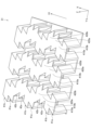
- FIG. 1 is a diagram schematically showing a schematic configuration of a heat exchanger according to an embodiment.
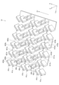
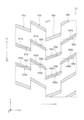
- FIG. 2 is a perspective view showing the perspective structure of the fin of the embodiment.
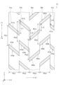
- FIG. 3 is a perspective sectional view showing the cross-sectional structure of the fin of the embodiment.
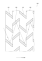
- FIG. 4 is a cross-sectional view showing the cross-sectional structure of the fin of the embodiment.
- FIG. 5 is a cross-sectional view showing the cross-sectional structure of the fin of the embodiment.
- FIG. 6 is a cross-sectional view showing the cross-sectional structure of a fin of a comparative example.
- FIG. 1 is a diagram schematically showing a schematic configuration of a heat exchanger according to an embodiment.
- FIG. 2 is a perspective view showing the perspective structure of the fin of the embodiment.
- FIG. 3 is a perspective sectional view showing the cross-sectional structure of the fin of the embodiment.
- FIG. 4 is a cross-sectional view showing the cross-sectional structure of the fin
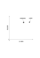
- FIG. 7 is a graph showing a comparison between the pressure loss and heat transfer coefficient of the heat exchanger using the fins of the embodiment and the pressure loss and heat transfer coefficient of the heat exchanger using the fins of the comparative example.
- FIG. 8 is a graph showing the relationship between the inclination angle and the heat transfer coefficient/pressure drop change ratio in the embodiment.
- FIG. 9 is a cross-sectional view showing a cross-sectional structure of a fin according to another embodiment.
- FIG. 10 is a cross-sectional view showing a cross-sectional structure of a fin according to another embodiment.
- FIG. 11 is a cross-sectional view showing a cross-sectional structure of a fin according to another embodiment.
- the heat exchanger 10 of this embodiment shown in FIG. 1 is a device that exchanges heat between a first fluid and a second fluid.
- the heat exchanger 10 includes a plurality of plate members 21, a plurality of plate members 22, a plurality of fins 31, and a plurality of fins 32.
- the plurality of plate members 21 and the plurality of plate members 22 are alternately arranged with gaps in the direction shown by arrow Z in the figure.
- the direction indicated by arrow Z will also be referred to as plate stacking direction Z.
- a space formed between the top surface 210 of the plate member 21 and the bottom surface 221 of the plate member 22 constitutes a flow path W11 through which the first fluid flows.
- a gap formed between the bottom surface 211 of the plate member 21 and the top surface 220 of the plate member 22 constitutes a flow path W12 through which the second fluid flows.
- the flow path W11 and the flow path W12 are formed to extend in the direction shown by arrow X.
- one of the directions indicated by arrows X is indicated by arrow X1, and the other direction is indicated by arrow X2.
- the first fluid flows in the flow path W11 in the direction indicated by the arrow X1.
- the second fluid flows in the flow path W12 in the direction indicated by the arrow X2. Note that the first fluid and the second fluid may flow in the same direction.
- the fins 31 are arranged in the flow path W11.
- the fins 31 have a function of increasing the heat transfer area for the first fluid by coming into contact with the first fluid.
- the fins 32 are arranged in the second flow path W12.
- the fins 32 have a function of increasing the heat transfer area to the second fluid by coming into contact with the second fluid.
- the first fluid flowing through the first flow path W11 and the second fluid flowing through the second flow path W12 exchange heat via the plate members 21 and 22.
- the plate members 21 and 22 correspond to a partition wall that partitions the first flow path W11 and the second flow path W12.
- the structure of the fins 31 and 32 will be explained. Note that since the structures of the fins 31 and 32 are the same, the structure of the fin 31 will be described below as a representative example. Further, the direction indicated by the arrow X1 shown in FIG. 1 is also referred to as the first fluid flow direction X1. Furthermore, the direction perpendicular to both the plate stacking direction Z and the first fluid flow direction X1 is also referred to as the channel width direction Y.
- the fin 31 has fin portions 41a, 41b, 42a, and 42b in this order along the first fluid flow direction X1.
- the fin portion 41a is arranged adjacent to the fin portion 42b in the first fluid flow direction X1, and the fin portion 41b, the fin portion 42a, and the fin portion 42b are further arranged in the first fluid flow direction X1 from the fin portion 41a. They are placed consecutively.
- Each of the fin portions 41a, 41b, 42a, and 42b has peak portions 410a, 410b, 420a, and 420b formed to protrude in the plate stacking direction Z at predetermined intervals in the channel width direction Y. Therefore, the cross-sectional shape of each fin portion 41a, 41b, 42a, 42b perpendicular to the first fluid flow direction X1 is formed in a wave shape.
- the fins 31 are so-called offset fins in which the peaks 410a, 410b, 420a, 420b of the fin portions 41a, 41b, 42a, 42b are arranged offset in the channel width direction Y.
- FIG. 3 is a perspective cross-sectional view showing the cross-sectional structure of the fin 31.
- FIG. 4 and 5 are cross-sectional views showing the cross-sectional structure of the fin 31.
- FIG. Note that FIGS. 4 and 5 show the same cross-sectional structure except for the reference numerals.
- portions 411a and 412a that are formed to extend in the plate stacking direction Z at the peak portion 410a of the fin portion 41a and are arranged to face each other in the channel width direction Y will be described. They are called side wall portions 411a and 412a.
- portions 411b, 412b, 421a, 422a, 421b, 422b at peak portions 410b, 420a, 420b of other fin portions 41b, 42a, 42b are referred to as side wall portions 411b, 412b, 421a, 422a, 421b, 422b.
- the end portions of the side wall portions 411b and 412b of the peak portion 410b of the fin portion 41b that are disposed on the upstream side in the first fluid flow direction X1 are indicated by reference numerals 413b and 414b.
- the downstream ends are designated 415b, 416b.
- the former end portions will be referred to as tip portions 413b and 414b, and the latter end portions will be referred to as rear end portions 415b and 416b.
- one direction of the channel width direction Y is referred to as a first predetermined direction Y1
- the other direction is referred to as a second predetermined direction Y2.
- the fin portion 41b is arranged in a direction intersecting the first fluid flow direction X1 so that the tip portions 413b, 414b of the side wall portions 411b, 412b are located in the first predetermined direction Y1 than the rear end portions 415b, 416b. It is formed to extend to. Side wall portions 411b and 412b of the fin portion 41b are arranged parallel to each other. In FIG. 4, virtual lines m21 and m22 are lines passing through the centers of the side walls 411b and 412b and parallel to the direction in which the side walls 411b and 412b extend, respectively.
- the side wall portions 411b and 412b are arranged so as to be inclined so that the virtual lines m21 and m22 form a predetermined angle ⁇ 20 in the second predetermined direction Y2 with respect to the first fluid flow direction X1. That is, the side wall portions 411b and 412b are formed to be inclined at a predetermined angle ⁇ 20 with respect to the first fluid flow direction X1.
- the fin portion 41a is arranged offset by a predetermined length L11 in the second predetermined direction Y2 with respect to the fin portion 41b.
- the fin portion 41a has the same structure as the fin portion 41b except that it is arranged offset, so a detailed description thereof will be omitted.
- the acute angle that the virtual lines m11 and m12 of the side wall parts 411a and 412a of the fin part 41a make with respect to the first fluid flow direction X1 is indicated by " ⁇ 10". That is, the side wall portions 411a and 412a are formed to be inclined at a predetermined angle ⁇ 10 with respect to the first fluid flow direction X1.
- the inclination angle ⁇ 10 of the side wall portions 411a, 412a of the fin portion 41a is set to the same value as the inclination angle ⁇ 20 of the side wall portions 411b, 412b of the fin portion 41b.
- the inclination angles ⁇ 10 and ⁇ 20 correspond to the first inclination angles.
- the fin portion 42a is arranged offset by a predetermined length L12 in the first predetermined direction Y1 with respect to the fin portion 41b.
- the fin portion 42a is arranged such that the first fluid flows in such a manner that the tip portions 423a, 424a of the side wall portions 421a, 422a are located in the second predetermined direction Y2 relative to the rear end portions 425a, 426a. It is formed to extend in a direction intersecting the direction X1.
- Side wall portions 421a and 422a of the fin portion 42b are arranged parallel to each other.
- virtual lines m31 and m32 are lines passing through the centers of the side walls 421a and 422a and parallel to the direction in which the side walls 421a and 422a extend, respectively.
- the side wall portions 421a and 422a are arranged so as to be inclined so that the virtual lines m31 and m32 form a predetermined angle ⁇ 30 in the second predetermined direction Y2 with respect to the first fluid flow direction X1. That is, the side wall portions 421a and 422a are formed to be inclined at a predetermined angle ⁇ 30 with respect to the first fluid flow direction X1.
- the side wall portions 421a, 422a of the fin portion 42a are arranged to be inclined in the opposite direction to the side wall portions 411a, 412a of the fin portion 41a and the side wall portions 411b, 412b of the fin portion 41b.
- the magnitude of the inclination angle ⁇ 30 of the side wall portions 421a and 422a is the same as the magnitude of the inclination angle ⁇ 20 of the side wall portions 411b and 412b of the fin portion 41b. Note that the magnitude of the inclination angle ⁇ 30 of the side wall portions 421a, 422a may be a different value from the magnitude of the inclination angle ⁇ 20 of the side wall portions 411b, 412b of the fin portion 41b.
- the fin portion 42b is arranged offset by a predetermined length L13 in the first predetermined direction Y1 with respect to the fin portion 42a.
- the fin portion 42b has the same structure as the fin portion 42a except that it is arranged offset, so a detailed description thereof will be omitted.
- the acute angle formed by the virtual lines m41 and m42 of the side wall portions 421b and 422b of the fin portion 42b with respect to the first fluid flow direction X1 is indicated by " ⁇ 40". That is, the side wall portions 421b and 422b are formed to be inclined at a predetermined angle ⁇ 40 with respect to the first fluid flow direction X1.
- the inclination angle ⁇ 40 of the side wall portions 421b, 422b of the fin portion 42b is set to the same value as the inclination angle ⁇ 30 of the side wall portions 421a, 422a of the fin portion 42a. Therefore, the inclination angles ⁇ 10, ⁇ 20, ⁇ 30, and ⁇ 40 of each fin portion 41a, 41b, 42a, and 42b have the same value. In this embodiment, the inclination angles ⁇ 30 and 40 correspond to the second inclination angle.
- the fin portion 41a disposed on the downstream side of the first fluid flow direction X1 with respect to the fin portion 42b extends by a predetermined length L14 in the second predetermined direction Y2 placed offset.
- the offset pitch L11 shown in FIG. 5 corresponds to the first offset pitch that is the offset pitch of two first heat transfer parts arranged adjacent to each other in the first fluid flow direction X1.
- the offset pitch L13 corresponds to a second offset pitch that is an offset pitch of two second heat transfer parts arranged adjacent to each other in the first fluid flow direction X1.
- the offset pitches L13 and L14 correspond to a third offset pitch that is an offset pitch of the first heat transfer section and the second heat transfer section that are arranged adjacent to each other in the first fluid flow direction X1.
- the offset pitches L11 to L14 may be the same value or may be different values.
- the side wall portion 421a of the fin portion 42a is arranged on the extension line of the virtual line m21 of the side wall portion 411b of the fin portion 41b. Furthermore, a side wall portion 422a of the fin portion 42a is arranged on an extension of the virtual line m22 of the side wall portion 412b of the fin portion 41b.
- the side wall portions 411a and 411b of the fin portions 41a and 41b are arranged side by side in the first fluid flow direction X1, and are also arranged offset in the first predetermined direction Y1 or the second predetermined direction Y2. This corresponds to the plurality of first heat transfer parts.
- the side wall portions 412a, 412b of the fin portions 41a, 41b are also arranged in parallel with the first fluid flow direction This corresponds to the first heat transfer section.
- the side wall portions 421a and 421b of the fin portions 42a and 42b are arranged side by side in the first fluid flow direction X1, and a second Corresponds to the heat transfer part.
- the side wall portions 422a, 422b of the fin portions 42a, 42b are also arranged in line with the first fluid flow direction Corresponds to the heat transfer part.
- the interval at which the side wall portions 411a and 412a are arranged in the channel width direction Y in the fin portion 41a is indicated by Pfy1.
- the intervals at which the side wall portions 411b, 412b, 421a, 422a, 421b, 422b are arranged in the channel width direction Y in the fin portions 41b, 42a, 42b are indicated by Pfy2, Pfy3, and Pfy4.
- each fin length Pfy1, Pfy2, Pfy3, and Pfy4 is set to the same value.
- the fin lengths Pfy1 and Pfy2 of the fin parts 41a and 41b correspond to the first vertical spacing
- the fin lengths Pfy3 and Pfy4 of the fin parts 42a and 42b correspond to the second vertical spacing.
- each fin pitch Pfx1, Pfx2 , Pfx3, and Pfx4 are set to the same value.
- the fin pitches Pfx1 and Pfx2 of the fin portions 41a and 41b correspond to the first lateral spacing
- the fin pitches Pfx3 and Pfx4 of the fin portions 42a and 42b correspond to the second lateral spacing.
- FIG. 6 shows a cross-sectional structure of a fin 100 of a heat exchanger of a comparative example.
- this fin 100 has fin portions 101 and 102 alternately in the fluid flow direction X100.
- the fin parts 101 and 102 have different inclination angles with respect to the fluid flow direction X100.
- the fin part 101 has the same inclination angle as the fin part 41a and the fin part 41b shown in FIG. 3
- the fin part 102 has the same inclination angle as the fin part 42a and the fin part 42b shown in FIG. It has a similar inclination angle.
- fluid flows, for example, as shown by the dashed-dotted arrow in the figure. Specifically, the fluid flows downstream while continuously colliding with the respective side surfaces of the fin parts 101 and 102. In this way, in the fins 100 of the heat exchanger of the comparative example, colliding flows are likely to occur, so pressure loss is likely to increase.
- the fin part 41b having the same slope as the fin part 41a is arranged on the downstream side of the fin part 41a in the first fluid flow direction X1. Therefore, when the first fluid that has passed through the fin portion 41a flows toward the fin portion 41b, a collision flow is unlikely to occur.
- a fin portion 42b having the same slope as the fin portion 42a is arranged downstream of the fin portion 42a in the first fluid flow direction X1. Therefore, even when the first fluid that has passed through the fin portions 42a flows toward the fin portions 42b, collision flows are unlikely to occur. In this way, in the heat exchanger 10 of this embodiment, it is possible to reduce the pressure loss of the first fluid when compared with the heat exchanger of the comparative example using the fins 100 shown in FIG.
- FIG. 7 is a graph of the experimental results.
- the measurement results when using the fin 100 of the comparative example are shown as triangular points, and the measurement results when using the fin 31 of the present embodiment are shown as round points.
- each fin portion 41a, 41b, 42a , 42b, fin pitches Pfx1, Pfx2, Pfx3, Pfx4, and fin lengths Pfy1, Pfy2, Pfy3, Pfy4 are set within the range shown by the following formulas f1 to f3. I know it's coming.
- FIG. 8 is a graph showing the results of experiments conducted by the inventors.
- the graph shown in FIG. 8 shows the relationship between the inclination angle ⁇ on the horizontal axis and the heat transfer coefficient/pressure drop change ratio on the vertical axis.
- the heat transfer coefficient/pressure drop change ratio is calculated by the following equation f4.
- the fins 31 include side wall portions 411a, 412a, 411b, 412b, 421a, 422a, 421b, and 422b.
- the side wall portions 411a, 412a, 411b, 412b have the tip portions 413a, 414a, 413b, 414b located in the first predetermined direction Y1 relative to the rear end portions 415a, 416a, 415b, 416b. It is formed to be inclined with respect to the first fluid flow direction X1.
- the side wall portions 421a, 422a, 421b, 422b are arranged in the first fluid flow direction such that the front end portions 423a, 424a, 423b, 424b are located in the second predetermined direction Y2 than the rear end portions 425a, 426a, 425b, 426b. It is formed to be inclined with respect to X1.
- the side wall portions 411a and 411b are arranged side by side in the first fluid flow direction X1 and offset in the first predetermined direction Y1 or the second predetermined direction Y2.
- the side wall portions 412a and 412b are also arranged in the same manner as the side wall portions 411a and 411b.
- the side wall portions 421a and 421b are arranged side by side in the first fluid flow direction X1 and offset in the first predetermined direction Y1 or the second predetermined direction Y2.
- the side wall portions 422a, 422b are also arranged in the same manner as the side wall portions 421a, 421b.
- the plurality of side wall parts 411a, 412a, 411b, 412b and the plurality of side wall parts 421a, 422a, 421b, 422b are arranged alternately along the first fluid flow direction X1.
- the side wall portions 411b, 412b and the side wall portions 421a, 422a which are arranged adjacent to each other in the first fluid flow direction X1, are arranged offset in the first predetermined direction Y1 or the second predetermined direction Y2. According to this configuration, a collision flow is less likely to occur in the first fluid, so it is possible to reduce the pressure loss of the first fluid.
- the fin 31 may have a fin portion 41c continuous to the fin portions 41a and 41b, and a fin portion 42c continuous to the fin portions 42a and 42b. good.
- the fin portion 41c has the same inclination angle as the fin portions 41a and 41b, and is arranged offset from the fin portion 41b.
- the fin portion 42c has the same inclination angle as the fin portions 42a and 42b, and is arranged offset from the fin portion 42b.
- the fin 31 may have three consecutive fin portions having the same inclination angle in the first fluid flow direction X1.
- the fin 31 is not limited to the structure shown in FIG. 9, and may have four or more fin portions having the same inclination angle consecutively in the first fluid flow direction X1.
- the inclination angle ⁇ 10 of the fin portion 41a and the inclination angle ⁇ 20 of the fin portion 41b may be different.
- the inclination angle ⁇ 30 of the fin portion 42a and the inclination angle ⁇ 40 of the fin portion 42b may be different.
- the offset pitches L11 to L14 of each fin portion 41a, 41b, 42a, and 42b can be changed as appropriate. For example, as shown in FIG. 11, offset pitch L11 and offset pitch L13 are set to the same value, offset pitch L12 and offset pitch L14 are set to the same value, and then offset pitch L11, L13 is set to the same value. and the offset pitches L12 and L14 may be set to different values.
- a plurality of the first heat transfer parts are further arranged at a first vertical interval in the first predetermined direction, and a plurality of the second heat transfer parts are further arranged at a second longitudinal interval in the first predetermined direction.
- a first horizontal interval is an interval at which the plurality of first heat transfer parts are arranged in the flow direction of the first fluid, and an interval at which the plurality of second heat transfer parts are arranged in the flow direction of the first fluid.
- the offset pitch of the two first heat transfer parts arranged adjacent to each other in the flow direction of the first fluid is defined as a first offset pitch
- the offset pitch of the second heat transfer section is defined as a second offset pitch
- the offset pitch of the first heat transfer section and the second heat transfer section arranged adjacently in the flow direction of the first fluid is defined as a third offset pitch.
Landscapes
- Engineering & Computer Science (AREA)
- Physics & Mathematics (AREA)
- Thermal Sciences (AREA)
- Mechanical Engineering (AREA)
- General Engineering & Computer Science (AREA)
- Geometry (AREA)
- Heat-Exchange Devices With Radiators And Conduit Assemblies (AREA)
Abstract
熱交換器のフィンは、第1伝熱部(411a,412a,411b,412b)と、第2伝熱部(421a,422a,421b,422b)と、備える。第1伝熱部は、第1流体の流れ方向の上流側に配置される先端部が、第1流体の流れ方向の下流側に配置される後端部よりも第1の所定方向に位置するように、第1流体の流れ方向に対して傾斜するように形成される。第2伝熱部は、第1流体の流れ方向の上流側に配置される先端部が、第1流体の流れ方向の下流側に配置される後端部よりも第2の所定方向に位置するように、第1流体の流れ方向に対して傾斜するように形成される。第1流体の流れ方向に並んで配置される複数の第1伝熱部と、第1流体の流れ方向に並んで配置される複数の第2伝熱部とが第1流体の流れ方向に沿って交互に配置される。
Description
本出願は、2022年5月2日に出願された日本国特許出願2022-075903号に基づくものであって、その優先権の利益を主張するものであり、その特許出願の全ての内容が、参照により本明細書に組み込まれる。
本開示は、熱交換器のフィンに関する。
従来、下記の特許文献1に記載の熱交換器がある。特許文献1に記載の熱交換器は、交互に積層された2種類の第1プレート及び第2プレートと、第1プレート及び第2プレートとの間に配置されるオフセットフィンとを備えている。第1プレートの下面と第2プレートの上面との間には、第1流体が流れる第1流路が形成されている。第1プレートの上面と第2プレートの下面との間には、第2流体が流れる第2流路が形成されている。オフセットフィンは第1流路及び第2流路にそれぞれ設けられている。オフセットフィンは、流体の流れ方向に対して異なる角度で傾斜する第1側壁部及び第2側壁部を交互に有している。
特許文献1に記載のオフセットフィンのように流体の流れ方向に対して所定角度だけ傾斜している場合、前縁効果だけでなく、衝突流が発生するため、流体に対する熱伝達率を向上させることが可能である。但し、衝突流は流体の圧力損失を大幅に上昇させる。特許文献1に記載のオフセットフィンでは、傾斜角度が異なる第1側壁部及び第2側壁部が交互に配置されているため、第1側壁部及び第2側壁部で衝突流が発生し易い。そのため、特許文献1に記載の熱交換器は、流体の圧力損失が増加し易い構造となっている。
本開示の目的は、圧力損失を低減することが可能な熱交換器のフィンを提供することにある。
本開示の一態様による熱交換器のフィンは、第1流体が流れる第1流路と、第2流体が流れる第2流路とを仕切る仕切壁を有し、仕切壁を介して第1流体と第2流体との間で熱交換を行う熱交換器において第1流体に接触するように第1流路に設けられるフィンである。フィンは、第1伝熱部と、第2伝熱部と、備える。第1流体の流れ方向に対して直交する方向を第1の所定方向とし、第1の所定方向の逆方向を第2の所定方向とするとき、第1伝熱部は、第1流体の流れ方向の上流側に配置される先端部が、第1流体の流れ方向の下流側に配置される後端部よりも第1の所定方向に位置するように、第1流体の流れ方向に対して傾斜するように形成される。第2伝熱部は、第1流体の流れ方向の上流側に配置される先端部が、第1流体の流れ方向の下流側に配置される後端部よりも第2の所定方向に位置するように、第1流体の流れ方向に対して傾斜するように形成される。複数の第1伝熱部が、第1流体の流れ方向に並んで配置されるとともに、第1の所定方向又は第2の所定方向にオフセットして配置される。複数の第2伝熱部が、第1流体の流れ方向に並んで配置されるとともに、第1の所定方向又は第2の所定方向にオフセットして配置される。第1流体の流れ方向に並んで配置される複数の第1伝熱部と、第1流体の流れ方向に並んで配置される複数の第2伝熱部とが第1流体の流れ方向に沿って交互に配置される。第1流体の流れ方向において隣り合って配置される第1伝熱部及び第2伝熱部は、第1の所定方向又は第2の所定方向にオフセットして配置されている。
この構成によれば、第1流体の流れ方向に沿って複数の第1伝熱部と複数の第2伝熱部とが交互に配置されているため、第1流体の流れ方向に沿って単数の第1伝熱部と単数の第2伝熱部とが交互に配置されている場合と比較すると、第1流体に衝突流が発生し難くなる。よって、第1流体の圧力損失を低減することが可能である。
以下、熱交換器のフィンの一実施形態について図面を参照しながら説明する。説明の理解を容易にするため、各図面において同一の構成要素に対しては可能な限り同一の符号を付して、重複する説明は省略する。
<実施形態>
図1に示される本実施形態の熱交換器10は、第1流体と第2流体との間で熱交換を行う機器である。熱交換器10は、複数のプレート部材21、複数のプレート部材22、複数のフィン31、及び複数のフィン32を備えている。
<実施形態>
図1に示される本実施形態の熱交換器10は、第1流体と第2流体との間で熱交換を行う機器である。熱交換器10は、複数のプレート部材21、複数のプレート部材22、複数のフィン31、及び複数のフィン32を備えている。
複数のプレート部材21及び複数のプレート部材22は、図中に矢印Zで示される方向に隙間を有して交互に配置されている。以下では、矢印Zで示される方向をプレート積層方向Zとも称する。プレート部材21の上面210とプレート部材22の底面221との間に形成される空間は、第1流体が流れる流路W11を構成している。プレート部材21の底面211とプレート部材22の上面220との間に形成される隙間は、第2流体が流れる流路W12を構成している。
流路W11及び流路W12は、矢印Xで示される方向に延びるように形成されている。図中には、矢印Xで示される方向のうちの一方向が矢印X1で示され、その他方向が矢印X2で示されている。流路W11には、矢印X1で示される方向に第1流体が流れている。流路W12には、矢印X2で示される方向に第2流体が流れている。なお、第1流体及び第2流体が同一の方向に流れていてもよい。
フィン31は流路W11に配置されている。フィン31は、第1流体に接触することにより、第1流体に対する伝熱面積を増加させる機能を有している。フィン32は第2流路W12に配置されている。フィン32は、第2流体に接触することにより、第2流体に対する伝熱面積を増加させる機能を有している。
この熱交換器10では、第1流路W11を流れる第1流体と、第2流路W12を流れる第2流体とがプレート部材21,22を介して熱交換を行う。本実施形態では、プレート部材21,22が、第1流路W11と第2流路W12とを仕切る仕切壁に相当する。
この熱交換器10では、第1流路W11を流れる第1流体と、第2流路W12を流れる第2流体とがプレート部材21,22を介して熱交換を行う。本実施形態では、プレート部材21,22が、第1流路W11と第2流路W12とを仕切る仕切壁に相当する。
次に、フィン31,32の構造について説明する。なお、フィン31,32の構造は同一であるため、以下ではフィン31の構造について代表して説明する。また、図1に示される矢印X1で示される方向を第1流体流れ方向X1とも称する。さらに、プレート積層方向Z及び第1流体流れ方向X1の両方に直交する方向を流路幅方向Yとも称する。
図2に示されるように、フィン31は、第1流体流れ方向X1に沿ってフィン部41a,41b,42a,42bを順に有している。フィン部42bの第1流体流れ方向X1にはフィン部41aが隣接して配置されており、当該フィン部41aから第1流体流れ方向X1にフィン部41b、フィン部42a、及びフィン部42bが更に連続して設けられている。
各フィン部41a,41b,42a,42bは、プレート積層方向Zに突出するように形成された山部410a,410b,420a,420bを流路幅方向Yに所定の間隔でそれぞれ有している。したがって、第1流体流れ方向X1に直交する各フィン部41a,41b,42a,42bの断面形状は波状に形成されている。フィン31は、各フィン部41a,41b,42a,42bの山部410a,410b,420a,420bが流路幅方向Yにずれて配置される、いわゆるオフセットフィンである。
図3は、フィン31の断面構造を示す斜視断面図である。図4及び図5は、フィン31の断面構造を示す断面図である。なお、図4及び図5には、符号を除いて同一の断面構造が示されている。
以下では、図3に示されるように、フィン部41aの山部410aにおいてプレート積層方向Zに延びるように形成され、且つ流路幅方向Yにおいて互いに対向して配置されている部分411a,412aを側壁部411a,412aと称する。同様に、他のフィン部41b,42a,42bの山部410b,420a,420bにおける部分411b,412b,421a,422a,421b,422bを側壁部411b,412b,421a,422a,421b,422bと称する。
以下では、図3に示されるように、フィン部41aの山部410aにおいてプレート積層方向Zに延びるように形成され、且つ流路幅方向Yにおいて互いに対向して配置されている部分411a,412aを側壁部411a,412aと称する。同様に、他のフィン部41b,42a,42bの山部410b,420a,420bにおける部分411b,412b,421a,422a,421b,422bを側壁部411b,412b,421a,422a,421b,422bと称する。
図4には、フィン部41bの山部410bの側壁部411b,412bにおいて第1流体流れ方向X1の上流側に配置される端部が符号413b,414bで示され、第1流体流れ方向X1の下流側に配置される端部が符号415b,416bで示されている。以下では、前者の端部を先端部413b,414bと称し、後者の端部を後端部415b,416bと称する。また、流路幅方向Yのうちの一方向を第1の所定方向Y1と称し、その他方向を第2の所定方向Y2と称する。
フィン部41bは、その側壁部411b,412bの先端部413b,414bが後端部415b,416bよりも第1の所定方向Y1に位置するように、第1流体流れ方向X1に対して交差する方向に延びるように形成されている。フィン部41bの側壁部411b,412bは互いに平行に配置されている。図4には、側壁部411b,412bの中心を通り、且つ側壁部411b,412bが延びる方向に平行な線である仮想線がm21,m22でそれぞれ示されている。側壁部411b,412bは、仮想線m21,m22が第1流体流れ方向X1に対して第2の所定方向Y2に所定角度θ20をなすように傾斜して配置されている。すなわち、側壁部411b,412bは、第1流体流れ方向X1に対して所定角度θ20で傾斜するように形成されている。
図5に示されるように、フィン部41aは、フィン部41bに対して第2の所定方向Y2に所定長さL11だけオフセットして配置されている。フィン部41aは、オフセットして配置されていることを除き、フィン部41bと同一の構造を有しているため、その詳細な説明は割愛する。なお、図4では、フィン部41aの側壁部411a,412aの仮想線m11,m12が第1流体流れ方向X1に対してなす鋭角側の角度が「θ10」で示されている。すなわち、側壁部411a,412aは、第1流体流れ方向X1に対して所定角度θ10で傾斜するように形成されている。本実施形態では、フィン部41aの側壁部411a,412aの傾斜角度θ10は、フィン部41bの側壁部411b,412bの傾斜角度θ20と同一の値に設定されている。本実施形態では、傾斜角度θ10,θ20が第1傾斜角度に相当する。
図5に示されるように、フィン部42aは、フィン部41bに対して第1の所定方向Y1に所定の長さL12だけオフセットして配置されている。図4に示されるように、フィン部42aは、その側壁部421a,422aの先端部423a,424aが後端部425a,426aよりも第2の所定方向Y2に位置するように、第1流体流れ方向X1に対して交差する方向に延びるように形成されている。フィン部42bの側壁部421a,422aは互いに平行に配置されている。図4には、側壁部421a,422aの中心を通り、且つ側壁部421a,422aが延びる方向に平行な線である仮想線がm31,m32でそれぞれ示されている。側壁部421a,422aは、仮想線m31,m32が第1流体流れ方向X1に対して第2の所定方向Y2に所定角度θ30をなすように傾斜して配置されている。すなわち、側壁部421a,422aは、第1流体流れ方向X1に対して所定角度θ30で傾斜するように形成されている。フィン部42aの側壁部421a,422aは、フィン部41aの側壁部411a,412a及びフィン部41bの側壁部411b,412bとは逆方向に傾斜して配置されている。
側壁部421a,422aの傾斜角度θ30の大きさは、フィン部41bの側壁部411b,412bの傾斜角度θ20の大きさと同一である。なお、側壁部421a,422aの傾斜角度θ30の大きさは、フィン部41bの側壁部411b,412bの傾斜角度θ20の大きさと異なる値であってもよい。
フィン部42bは、フィン部42aに対して第1の所定方向Y1に所定の長さL13だけオフセットして配置されている。フィン部42bは、オフセットして配置されていることを除き、フィン部42aと同一の構造を有しているため、その詳細な説明は割愛する。なお、図4では、フィン部42bの側壁部421b,422bの仮想線m41,m42が第1流体流れ方向X1に対してなす鋭角側の角度が「θ40」で示されている。すなわち、側壁部421b,422bは、第1流体流れ方向X1に対して所定角度θ40で傾斜するように形成されている。本実施形態では、フィン部42bの側壁部421b,422bの傾斜角度θ40がフィン部42aの側壁部421a,422aの傾斜角度θ30と同一の値に設定されている。したがって、各フィン部41a,41b,42a,42bの傾斜角度θ10,θ20,θ30,θ40のそれぞれの大きさは同一の値である。本実施形態では、傾斜角度θ30,40が第2傾斜角度に相当する。
図5に示されるように、フィン部42bに対して第1流体流れ方向X1の下流側に配置されるフィン部41aは、フィン部42bに対して第2の所定方向Y2に所定長さL14だけオフセットして配置されている。
なお、本実施形態では、図5に示されるオフセットピッチL11が、第1流体流れ方向X1に隣り合って配置される2つの第1伝熱部のオフセットピッチである第1オフセットピッチに相当する。また、オフセットピッチL13が、第1流体流れ方向X1に隣り合って配置される2つの第2伝熱部のオフセットピッチである第2オフセットピッチに相当する。さらに、オフセットピッチL13,L14が、第1流体流れ方向X1に隣り合って配置される第1伝熱部及び第2伝熱部のオフセットピッチである第3オフセットピッチに相当する。オフセットピッチL11~L14は同一の値でもよいし、互いに異なる値であってもよい。
なお、本実施形態では、図5に示されるオフセットピッチL11が、第1流体流れ方向X1に隣り合って配置される2つの第1伝熱部のオフセットピッチである第1オフセットピッチに相当する。また、オフセットピッチL13が、第1流体流れ方向X1に隣り合って配置される2つの第2伝熱部のオフセットピッチである第2オフセットピッチに相当する。さらに、オフセットピッチL13,L14が、第1流体流れ方向X1に隣り合って配置される第1伝熱部及び第2伝熱部のオフセットピッチである第3オフセットピッチに相当する。オフセットピッチL11~L14は同一の値でもよいし、互いに異なる値であってもよい。
図4に示されるように、フィン部41bの側壁部411bの仮想線m21の延長線上にはフィン部42aの側壁部421aが配置されている。また、フィン部41bの側壁部412bの仮想線m22の延長線上にはフィン部42aの側壁部422aが配置されている。本実施形態では、フィン部41a,41bの側壁部411a,411bが、第1流体流れ方向X1に並んで配置されるとともに、第1の所定方向Y1又は第2の所定方向Y2にずれて配置される複数の第1伝熱部に相当する。また、フィン部41a,41bの側壁部412a,412bも、第1流体流れ方向X1に並んで配置されるとともに、第1の所定方向Y1又は第2の所定方向Y2にずれて配置される複数の第1伝熱部に相当する。一方、フィン部42a,42bの側壁部421a,421bが、第1流体流れ方向X1に並んで配置されるとともに、第1の所定方向Y1又は第2の所定方向Y2にずれて配置される第2伝熱部に相当する。また、フィン部42a,42bの側壁部422a,422bも、第1流体流れ方向X1に並んで配置されるとともに、第1の所定方向Y1又は第2の所定方向Y2にずれて配置される第2伝熱部に相当する。
また、図5には、フィン部41aにおいて側壁部411a,412aが流路幅方向Yにおいて配置されている間隔がPfy1で示されている。同様に、フィン部41b,42a,42bにおいて側壁部411b,412b,421a,422a,421b,422bが流路幅方向Yにおいて配置されている間隔がPfy2,Pfy3,Pfy4で示されている。これらをフィン長さPfy1,Pfy2,Pfy3,Pfy4とするとき、各フィン長さPfy1,Pfy2,Pfy3,Pfy4は同一の値に設定されている。本実施形態では、フィン部41a,41bのフィン長さPfy1,Pfy2が第1の縦間隔に相当し、フィン部42a,42bのフィン長さPfy3,Pfy4が第2の縦間隔に相当する。
さらに、図5に示されるように、各フィン部41a,41b,42a,42bの第1流体流れ方向X1の長さをフィンピッチPfx1,Pfx2,Pfx3,Pfx4とするとき、各フィンピッチPfx1,Pfx2,Pfx3,Pfx4は同一の値に設定されている。本実施形態では、フィン部41a,41bのフィンピッチPfx1,Pfx2が第1の横間隔に相当し、フィン部42a,42bのフィンピッチPfx3,Pfx4が第2の横間隔に相当する。
次に、本実施形態の熱交換器10の作用及び効果について説明する。
図6は、比較例の熱交換器のフィン100の断面構造を示したものである。図6に示されるように、このフィン100は、流体の流れ方向X100にフィン部101,102を交互に有している。フィン部101,102は、流体の流れ方向X100に対する傾斜角度が異なっている。具体的には、フィン部101は、図3に示されるフィン部41a及びフィン部41bと同様の傾斜角度を有しており、フィン部102は、図3に示されるフィン部42a及びフィン部42bと同様の傾斜角度を有している。
図6は、比較例の熱交換器のフィン100の断面構造を示したものである。図6に示されるように、このフィン100は、流体の流れ方向X100にフィン部101,102を交互に有している。フィン部101,102は、流体の流れ方向X100に対する傾斜角度が異なっている。具体的には、フィン部101は、図3に示されるフィン部41a及びフィン部41bと同様の傾斜角度を有しており、フィン部102は、図3に示されるフィン部42a及びフィン部42bと同様の傾斜角度を有している。
図6に示される比較例の熱交換器のフィン100では、例えば図中に一点鎖線の矢印で示されるように流体が流れる。具体的には、流体は、フィン部101,102のそれぞれの側面に連続して衝突しながら下流に向かって流れる。このように比較例の熱交換器のフィン100では衝突流が発生し易いため、圧力損失が大きくなり易い。
これに対して、本実施形態の熱交換器10では、フィン部41aの第1流体流れ方向X1の下流側には、フィン部41aと同様の傾斜を有するフィン部41bが配置されている。そのため、フィン部41aを通過した第1流体がフィン部41bに向かって流れる際に衝突流が発生し難い。同様に、フィン部42aの第1流体流れ方向X1の下流側には、フィン部42aと同様の傾斜を有するフィン部42bが配置されている。そのため、フィン部42aを通過した第1流体がフィン部42bに向かって流れる際にも衝突流が発生し難い。このように、本実施形態の熱交換器10では、図6に示されるフィン100を用いる比較例の熱交換器と比較すると、第1流体の圧力損失を低減することが可能である。
発明者らは、図6に示される比較例のフィン100を用いた熱交換器における流体の圧力損失及び熱伝達率と、本実施形態のフィン31を用いた熱交換器における流体の圧力損失及び熱伝達率とを実験的に計測した。図7は、その実験結果をグラフ化したものである。なお、図7では、比較例のフィン100を用いた場合の計測結果が三角の点で示され、本実施形態のフィン31を用いた場合の計測結果が丸の点で示されている。
図7に示されるように、本実施形態のフィン31を用いた熱交換器は、比較例のフィン100を用いた熱交換器と比較すると、熱伝達率に関しては同等の性能を維持しつつ、流体の圧力損失を30%程度低減することが可能である。
なお、発明者らにより行われた別の実験結果によると、熱交換器の熱伝達率の上昇と、流体の圧力損失の低減との両立を図るためには、各フィン部41a,41b,42a,42bの傾斜角度θ10,θ20,θ30,θ40、フィンピッチPfx1,Pfx2,Pfx3,Pfx4、及びフィン長さPfy1,Pfy2,Pfy3,Pfy4を次式f1~f3に示される範囲に設定することが有効でることが分かっている。
なお、発明者らにより行われた別の実験結果によると、熱交換器の熱伝達率の上昇と、流体の圧力損失の低減との両立を図るためには、各フィン部41a,41b,42a,42bの傾斜角度θ10,θ20,θ30,θ40、フィンピッチPfx1,Pfx2,Pfx3,Pfx4、及びフィン長さPfy1,Pfy2,Pfy3,Pfy4を次式f1~f3に示される範囲に設定することが有効でることが分かっている。
1°<θ10=θ20=θ30=θ40<29° (f1)
0.1mm<Pfx1=Pfx2=Pfx3=Pfx4<3.0mm (f2)
0.1mm<Pfy1=Pfy2=Pfy3=Pfy4<3.0mm (f3)
0.1mm<Pfx1=Pfx2=Pfx3=Pfx4<3.0mm (f2)
0.1mm<Pfy1=Pfy2=Pfy3=Pfy4<3.0mm (f3)
図8は、発明者らにより行われた実験の結果を示すグラフである。図8に示されるグラフは、傾斜角θを横軸に、熱伝達率/圧損変化比率を縦軸にそれぞれとって、それらの関係を示したものである。傾斜角度θは、「θ=θ10=θ20=θ30=θ40」である。熱伝達率/圧損変化比率は以下の式f4により演算される。
熱伝達率/圧損変化比率=(熱伝達率/圧損)/(熱伝達率/圧損)θ=0deg (f4)
熱伝達率/圧損変化比率=(熱伝達率/圧損)/(熱伝達率/圧損)θ=0deg (f4)
図8に示されるように、傾斜角度θが「1°<θ<29°」を満たしている場合、熱伝達率/圧損変化比率を高い値に維持することが可能である。よって、各フィン部41a,41b,42a,42bの傾斜角度θ10,θ20,θ30,θ40を上記の式f1を満たすように設定することが有効である。
なお、第2流路W12に配置されるフィン32として、フィン31と同一又は類似の構造のフィンを用いれば、第2流路W12でも第1流路W11と同一又は類似の作用及び効果を得ることが可能である。
以上説明したように、本実施形態の熱交換器10では、フィン31が側壁部411a,412a,411b,412b,421a,422a,421b,422bを備える。図4に示されるように、側壁部411a,412a,411b,412bは、先端部413a,414a,413b,414bが後端部415a,416a,415b,416bよりも第1の所定方向Y1に位置するように、第1流体流れ方向X1に対して傾斜するように形成されている。側壁部421a,422a,421b,422bは、先端部423a,424a,423b,424bが後端部425a,426a,425b,426bよりも第2の所定方向Y2に位置するように、第1流体流れ方向X1に対して傾斜するように形成されている。側壁部411a,411bは、第1流体流れ方向X1に並んで配置されるとともに、第1の所定方向Y1又は第2の所定方向Y2にオフセットして配置されている。側壁部412a,412bも側壁部411a,411bと同様に配置されている。側壁部421a,421bは、第1流体流れ方向X1に並んで配置されるとともに、第1の所定方向Y1又は第2の所定方向Y2にオフセットして配置されている。側壁部422a,422bも側壁部421a,421bと同様に配置されている。複数の側壁部411a,412a,411b,412b及び複数の側壁部421a,422a,421b,422bは第1流体流れ方向X1に沿って交互に配置されている。第1流体流れ方向X1において隣り合って配置される側壁部411b,412b及び側壁部421a,422aは、第1の所定方向Y1又は第2の所定方向Y2にオフセットして配置されている。この構成によれば、第1流体に衝突流が発生し難くなるため、第1流体の圧力損失を低減することが可能である。
<他の実施形態>
なお、上記実施形態は、以下の形態にて実施することもできる。
・図9に示されるように、フィン31は、フィン部41a,41bに連続するようにフィン部41cを有し、且つフィン部42a,42bに連続するようにフィン部42cを有していてもよい。フィン部41cは、フィン部41a,41bと同様の傾斜角度を有し、且つフィン部41bに対してオフセットして配置されている。フィン部42cは、フィン部42a,42bと同様の傾斜角度を有し、且つフィン部42bに対してオフセットして配置されている。このように、フィン31は、同様の傾斜角度を有するフィン部を第1流体流れ方向X1に連続して3つ有するものであってもよい。また、フィン31は、図9に示される構造に限らず、同様の傾斜角度を有するフィン部を第1流体流れ方向X1に連続して4つ以上有するものであってもよい。
なお、上記実施形態は、以下の形態にて実施することもできる。
・図9に示されるように、フィン31は、フィン部41a,41bに連続するようにフィン部41cを有し、且つフィン部42a,42bに連続するようにフィン部42cを有していてもよい。フィン部41cは、フィン部41a,41bと同様の傾斜角度を有し、且つフィン部41bに対してオフセットして配置されている。フィン部42cは、フィン部42a,42bと同様の傾斜角度を有し、且つフィン部42bに対してオフセットして配置されている。このように、フィン31は、同様の傾斜角度を有するフィン部を第1流体流れ方向X1に連続して3つ有するものであってもよい。また、フィン31は、図9に示される構造に限らず、同様の傾斜角度を有するフィン部を第1流体流れ方向X1に連続して4つ以上有するものであってもよい。
・図10に示されるように、フィン部41aの傾斜角度θ10とフィン部41bの傾斜角度θ20とが異なっていてもよい。同様に、フィン部42aの傾斜角度θ30とフィン部42bの傾斜角度θ40とが異なっていてもよい。
・各フィン部41a,41b,42a,42bのオフセットピッチL11~L14は適宜変更可能である。例えば、図11に示されるように、オフセットピッチL11とオフセットピッチL13とを同一の値に設定し、且つオフセットピッチL12とオフセットピッチL14とを同一の値に設定した上で、オフセットピッチL11,L13とオフセットピッチL12,L14とを異なる値に設定してもよい。
・各フィン部41a,41b,42a,42bのオフセットピッチL11~L14は適宜変更可能である。例えば、図11に示されるように、オフセットピッチL11とオフセットピッチL13とを同一の値に設定し、且つオフセットピッチL12とオフセットピッチL14とを同一の値に設定した上で、オフセットピッチL11,L13とオフセットピッチL12,L14とを異なる値に設定してもよい。
・本開示は上記の具体例に限定されるものではない。上記の具体例に、当業者が適宜設計変更を加えたものも、本開示の特徴を備えている限り、本開示の範囲に包含される。前述した各具体例が備える各要素、及びその配置、条件、形状等は、例示したものに限定されるわけではなく適宜変更することができる。前述した各具体例が備える各要素は、技術的な矛盾が生じない限り、適宜組み合わせを変えることができる。
<付記>
本発明の特徴を以下の通り示す。
前記第1伝熱部は、前記第1の所定方向に第1の縦間隔で更に複数配置されており、前記第2伝熱部は、前記第1の所定方向に第2の縦間隔で更に複数配置されており、前記第1の縦間隔及び前記第2の縦間隔が互いに等しくなっている、請求項1~6のいずれか一項に記載の熱交換器のフィン。
本発明の特徴を以下の通り示す。
前記第1伝熱部は、前記第1の所定方向に第1の縦間隔で更に複数配置されており、前記第2伝熱部は、前記第1の所定方向に第2の縦間隔で更に複数配置されており、前記第1の縦間隔及び前記第2の縦間隔が互いに等しくなっている、請求項1~6のいずれか一項に記載の熱交換器のフィン。
前記第1流体の流れ方向において複数の前記第1伝熱部が配置される間隔を第1の横間隔とし、前記第1流体の流れ方向において複数の前記第2伝熱部が配置される間隔を第2の横間隔とするとき、前記第1の横間隔及び前記第2の横間隔が互いに等しくなっている、請求項1~8のいずれか一項に記載の熱交換器のフィン。
前記第1流体の流れ方向に隣り合って配置される2つの前記第1伝熱部のオフセットピッチを第1オフセットピッチとし、前記第1流体の流れ方向に隣り合って配置される2つの前記第2伝熱部のオフセットピッチを第2オフセットピッチとし、前記第1流体の流れ方向に隣り合って配置される前記第1伝熱部及び前記第2伝熱部のオフセットピッチを第3オフセットピッチとするとき、前記第3オフセットピッチは、前記第1オフセットピッチ及び前記第2オフセットピッチと異なっている、請求項1~10のいずれか一項に記載の熱交換器のフィン。
Claims (11)
- 第1流体が流れる第1流路(W11)と、第2流体が流れる第2流路(W12)とを仕切る仕切壁(21,22)を有し、前記仕切壁を介して前記第1流体と前記第2流体との間で熱交換を行う熱交換器(10)において前記第1流体に接触するように前記第1流路に設けられるフィン(31)であって、
前記第1流体の流れ方向に対して直交する方向を第1の所定方向とし、前記第1の所定方向の逆方向を第2の所定方向とするとき、
前記第1流体の流れ方向の上流側に配置される先端部が、前記第1流体の流れ方向の下流側に配置される後端部よりも前記第1の所定方向に位置するように、前記第1流体の流れ方向に対して傾斜するように形成される第1伝熱部(411a,412a,411b,412b)と、
前記第1流体の流れ方向の上流側に配置される先端部が、前記第1流体の流れ方向の下流側に配置される後端部よりも前記第2の所定方向に位置するように、前記第1流体の流れ方向に対して傾斜するように形成される第2伝熱部(421a,422a,421b,422b)と、備え、
複数の第1伝熱部が、前記第1流体の流れ方向に並んで配置されるとともに、前記第1の所定方向又は前記第2の所定方向にオフセットして配置され、
複数の第2伝熱部が、前記第1流体の流れ方向に並んで配置されるとともに、前記第1の所定方向又は前記第2の所定方向にオフセットして配置され、
前記第1流体の流れ方向に並んで配置される複数の前記第1伝熱部と、前記第1流体の流れ方向に並んで配置される複数の前記第2伝熱部とが前記第1流体の流れ方向に沿って交互に配置され、
前記第1流体の流れ方向において隣り合って配置される前記第1伝熱部及び前記第2伝熱部は、前記第1の所定方向又は前記第2の所定方向にオフセットして配置されている
熱交換器のフィン。 - 複数の前記第1伝熱部は、前記第1流体の流れ方向において2以上の数で連続して配置されており、
複数の前記第2伝熱部は、前記第1流体の流れ方向において2以上の数で連続して配置されている
請求項1に記載の熱交換器のフィン。 - 前記第1伝熱部が連続して配置される数、及び前記第2伝熱部が連続して配置される数は2つである
請求項2に記載の熱交換器のフィン。 - 複数の前記第1伝熱部は互いに平行であり、
複数の前記第2伝熱部は互いに平行であり、
複数の前記第1伝熱部が前記第1流体の流れ方向に対してなす鋭角側の傾斜角度を第1傾斜角度とし、複数の前記第2伝熱部が前記第1流体の流れ方向に対してなす鋭角側の傾斜角度を第2傾斜角度とするとき、
前記第1傾斜角度及び前記第2傾斜角度が互いに等しくなっている
請求項1~3のいずれか一項に記載の熱交換器のフィン。 - 前記第1傾斜角度及び前記第2傾斜角度のそれぞれの角度の大きさをθとするとき、角度θは次式、
1°≦θ≦29°
の範囲に設定されている
請求項4に記載の熱交換器のフィン。 - 複数の前記第1伝熱部は互いに平行であり、
複数の前記第2伝熱部は互いに平行であり、
複数の前記第1伝熱部が前記第1流体の流れ方向に対してなす鋭角側の傾斜角度を第1傾斜角度とし、複数の前記第2伝熱部が前記第1流体の流れ方向に対してなす鋭角側の傾斜角度を第2傾斜角度とするとき、
前記第1傾斜角度及び前記第2傾斜角度が互いに異なっている
請求項1~3のいずれか一項に記載の熱交換器のフィン。 - 前記第1伝熱部は、前記第1の所定方向に第1の縦間隔で更に複数配置されており、
前記第2伝熱部は、前記第1の所定方向に第2の縦間隔で更に複数配置されており、
前記第1の縦間隔及び前記第2の縦間隔が互いに等しくなっている
請求項1に記載の熱交換器のフィン。 - 前記第1の縦間隔及び前記第2の縦間隔のそれぞれの長さをPfyとするとき、長さpfxは次式、
0.1mm≦Pfy≦3.0mm
の範囲に設定されている
請求項7に記載の熱交換器のフィン。 - 前記第1流体の流れ方向において複数の前記第1伝熱部が配置される間隔を第1の横間隔とし、
前記第1流体の流れ方向において複数の前記第2伝熱部が配置される間隔を第2の横間隔とするとき、
前記第1の横間隔及び前記第2の横間隔が互いに等しくなっている
請求項1に記載の熱交換器のフィン。 - 前記第1の横間隔及び前記第2の横間隔のそれぞれの間隔をPfxとするとき、間隔pfxは次式、
0.1mm≦Pfx≦3.0mm
の範囲に設定されている
請求項9に記載の熱交換器のフィン。 - 前記第1流体の流れ方向に隣り合って配置される2つの前記第1伝熱部のオフセットピッチを第1オフセットピッチとし、前記第1流体の流れ方向に隣り合って配置される2つの前記第2伝熱部のオフセットピッチを第2オフセットピッチとし、前記第1流体の流れ方向に隣り合って配置される前記第1伝熱部及び前記第2伝熱部のオフセットピッチを第3オフセットピッチとするとき、
前記第3オフセットピッチは、前記第1オフセットピッチ及び前記第2オフセットピッチと異なっている
請求項1に記載の熱交換器のフィン。
Applications Claiming Priority (2)
| Application Number | Priority Date | Filing Date | Title |
|---|---|---|---|
| JP2022075903 | 2022-05-02 | ||
| JP2022-075903 | 2022-05-02 |
Publications (1)
| Publication Number | Publication Date |
|---|---|
| WO2023214549A1 true WO2023214549A1 (ja) | 2023-11-09 |
Family
ID=88646474
Family Applications (1)
| Application Number | Title | Priority Date | Filing Date |
|---|---|---|---|
| PCT/JP2023/016902 Ceased WO2023214549A1 (ja) | 2022-05-02 | 2023-04-28 | 熱交換器のフィン |
Country Status (1)
| Country | Link |
|---|---|
| WO (1) | WO2023214549A1 (ja) |
Citations (2)
| Publication number | Priority date | Publication date | Assignee | Title |
|---|---|---|---|---|
| JPH01170881U (ja) * | 1988-05-13 | 1989-12-04 | ||
| CN113624042A (zh) * | 2021-07-28 | 2021-11-09 | 祥博传热科技股份有限公司 | 相变式冷却换热器 |
-
2023
- 2023-04-28 WO PCT/JP2023/016902 patent/WO2023214549A1/ja not_active Ceased
Patent Citations (2)
| Publication number | Priority date | Publication date | Assignee | Title |
|---|---|---|---|---|
| JPH01170881U (ja) * | 1988-05-13 | 1989-12-04 | ||
| CN113624042A (zh) * | 2021-07-28 | 2021-11-09 | 祥博传热科技股份有限公司 | 相变式冷却换热器 |
Similar Documents
| Publication | Publication Date | Title |
|---|---|---|
| JP5487423B2 (ja) | 熱交換器 | |
| JP5156773B2 (ja) | コルゲートフィンおよびそれを備える熱交換器 | |
| CN100552360C (zh) | 冷却热交换器 | |
| JP7480487B2 (ja) | 熱交換器 | |
| CN1284958C (zh) | 带有钎焊板件的热交换器 | |
| CN112414185B (zh) | 板式换热器 | |
| CN1875240A (zh) | 热交换器的流道以及带有这种流道的热交换器 | |
| CN110741218A (zh) | 热交换器及波纹状翅片 | |
| CN104937362B (zh) | 热交换器 | |
| RS65003B1 (sr) | Ploča za prenos toplote | |
| CN115325864A (zh) | 用于板式热交换器的具有不对称性波纹结构的板 | |
| US6942024B2 (en) | Corrugated heat exchange element | |
| CN114370777B (zh) | 印刷电路板换热器的换热通道结构及印刷电路板换热器 | |
| WO2023214549A1 (ja) | 熱交換器のフィン | |
| CN113950605B (zh) | 热交换器 | |
| JP7424251B2 (ja) | 熱交換器 | |
| CN112146484B (zh) | 板式换热器 | |
| US12117250B2 (en) | Heat exchanger with variable cross sectional flow path areas | |
| CN104919265B (zh) | 催化剂反应器 | |
| WO2012113836A1 (de) | Wärmetauscher | |
| JP2884201B2 (ja) | 熱交換器 | |
| JP2006266528A (ja) | 熱交換器用偏平チューブ | |
| FI4343255T3 (fi) | Levylämmönvaihdin | |
| TWI855912B (zh) | 線性馬達冷卻模組 | |
| JP2013050303A (ja) | コルゲートフィンおよびそれを備える熱交換器 |
Legal Events
| Date | Code | Title | Description |
|---|---|---|---|
| 121 | Ep: the epo has been informed by wipo that ep was designated in this application |
Ref document number: 23799479 Country of ref document: EP Kind code of ref document: A1 |
|
| NENP | Non-entry into the national phase |
Ref country code: DE |
|
| 122 | Ep: pct application non-entry in european phase |
Ref document number: 23799479 Country of ref document: EP Kind code of ref document: A1 |
|
| NENP | Non-entry into the national phase |
Ref country code: JP |