WO2023214530A1 - 非水電解質電池用リード線、絶縁膜および非水電解質電池 - Google Patents
非水電解質電池用リード線、絶縁膜および非水電解質電池 Download PDFInfo
- Publication number
- WO2023214530A1 WO2023214530A1 PCT/JP2023/016547 JP2023016547W WO2023214530A1 WO 2023214530 A1 WO2023214530 A1 WO 2023214530A1 JP 2023016547 W JP2023016547 W JP 2023016547W WO 2023214530 A1 WO2023214530 A1 WO 2023214530A1
- Authority
- WO
- WIPO (PCT)
- Prior art keywords
- insulating film
- conductor
- aqueous electrolyte
- electrolyte battery
- lead wire
- Prior art date
- Legal status (The legal status is an assumption and is not a legal conclusion. Google has not performed a legal analysis and makes no representation as to the accuracy of the status listed.)
- Ceased
Links
Images





Classifications
-
- H—ELECTRICITY
- H01—ELECTRIC ELEMENTS
- H01M—PROCESSES OR MEANS, e.g. BATTERIES, FOR THE DIRECT CONVERSION OF CHEMICAL ENERGY INTO ELECTRICAL ENERGY
- H01M50/00—Constructional details or processes of manufacture of the non-active parts of electrochemical cells other than fuel cells, e.g. hybrid cells
- H01M50/10—Primary casings; Jackets or wrappings
- H01M50/172—Arrangements of electric connectors penetrating the casing
- H01M50/174—Arrangements of electric connectors penetrating the casing adapted for the shape of the cells
- H01M50/178—Arrangements of electric connectors penetrating the casing adapted for the shape of the cells for pouch or flexible bag cells
-
- H—ELECTRICITY
- H01—ELECTRIC ELEMENTS
- H01M—PROCESSES OR MEANS, e.g. BATTERIES, FOR THE DIRECT CONVERSION OF CHEMICAL ENERGY INTO ELECTRICAL ENERGY
- H01M50/00—Constructional details or processes of manufacture of the non-active parts of electrochemical cells other than fuel cells, e.g. hybrid cells
- H01M50/10—Primary casings; Jackets or wrappings
- H01M50/183—Sealing members
- H01M50/184—Sealing members characterised by their shape or structure
-
- H—ELECTRICITY
- H01—ELECTRIC ELEMENTS
- H01M—PROCESSES OR MEANS, e.g. BATTERIES, FOR THE DIRECT CONVERSION OF CHEMICAL ENERGY INTO ELECTRICAL ENERGY
- H01M50/00—Constructional details or processes of manufacture of the non-active parts of electrochemical cells other than fuel cells, e.g. hybrid cells
- H01M50/10—Primary casings; Jackets or wrappings
- H01M50/183—Sealing members
- H01M50/19—Sealing members characterised by the material
- H01M50/193—Organic material
-
- H—ELECTRICITY
- H01—ELECTRIC ELEMENTS
- H01M—PROCESSES OR MEANS, e.g. BATTERIES, FOR THE DIRECT CONVERSION OF CHEMICAL ENERGY INTO ELECTRICAL ENERGY
- H01M50/00—Constructional details or processes of manufacture of the non-active parts of electrochemical cells other than fuel cells, e.g. hybrid cells
- H01M50/10—Primary casings; Jackets or wrappings
- H01M50/183—Sealing members
- H01M50/19—Sealing members characterised by the material
- H01M50/197—Sealing members characterised by the material having a layered structure
-
- H—ELECTRICITY
- H01—ELECTRIC ELEMENTS
- H01M—PROCESSES OR MEANS, e.g. BATTERIES, FOR THE DIRECT CONVERSION OF CHEMICAL ENERGY INTO ELECTRICAL ENERGY
- H01M50/00—Constructional details or processes of manufacture of the non-active parts of electrochemical cells other than fuel cells, e.g. hybrid cells
- H01M50/10—Primary casings; Jackets or wrappings
- H01M50/183—Sealing members
- H01M50/19—Sealing members characterised by the material
- H01M50/198—Sealing members characterised by the material characterised by physical properties, e.g. adhesiveness or hardness
-
- H—ELECTRICITY
- H01—ELECTRIC ELEMENTS
- H01M—PROCESSES OR MEANS, e.g. BATTERIES, FOR THE DIRECT CONVERSION OF CHEMICAL ENERGY INTO ELECTRICAL ENERGY
- H01M50/00—Constructional details or processes of manufacture of the non-active parts of electrochemical cells other than fuel cells, e.g. hybrid cells
- H01M50/50—Current conducting connections for cells or batteries
- H01M50/531—Electrode connections inside a battery casing
- H01M50/533—Electrode connections inside a battery casing characterised by the shape of the leads or tabs
-
- H—ELECTRICITY
- H01—ELECTRIC ELEMENTS
- H01M—PROCESSES OR MEANS, e.g. BATTERIES, FOR THE DIRECT CONVERSION OF CHEMICAL ENERGY INTO ELECTRICAL ENERGY
- H01M50/00—Constructional details or processes of manufacture of the non-active parts of electrochemical cells other than fuel cells, e.g. hybrid cells
- H01M50/50—Current conducting connections for cells or batteries
- H01M50/543—Terminals
- H01M50/547—Terminals characterised by the disposition of the terminals on the cells
- H01M50/55—Terminals characterised by the disposition of the terminals on the cells on the same side of the cell
-
- H—ELECTRICITY
- H01—ELECTRIC ELEMENTS
- H01M—PROCESSES OR MEANS, e.g. BATTERIES, FOR THE DIRECT CONVERSION OF CHEMICAL ENERGY INTO ELECTRICAL ENERGY
- H01M50/00—Constructional details or processes of manufacture of the non-active parts of electrochemical cells other than fuel cells, e.g. hybrid cells
- H01M50/50—Current conducting connections for cells or batteries
- H01M50/543—Terminals
- H01M50/552—Terminals characterised by their shape
- H01M50/553—Terminals adapted for prismatic, pouch or rectangular cells
- H01M50/557—Plate-shaped terminals
-
- H—ELECTRICITY
- H01—ELECTRIC ELEMENTS
- H01M—PROCESSES OR MEANS, e.g. BATTERIES, FOR THE DIRECT CONVERSION OF CHEMICAL ENERGY INTO ELECTRICAL ENERGY
- H01M50/00—Constructional details or processes of manufacture of the non-active parts of electrochemical cells other than fuel cells, e.g. hybrid cells
- H01M50/50—Current conducting connections for cells or batteries
- H01M50/571—Methods or arrangements for affording protection against corrosion; Selection of materials therefor
-
- H—ELECTRICITY
- H01—ELECTRIC ELEMENTS
- H01M—PROCESSES OR MEANS, e.g. BATTERIES, FOR THE DIRECT CONVERSION OF CHEMICAL ENERGY INTO ELECTRICAL ENERGY
- H01M50/00—Constructional details or processes of manufacture of the non-active parts of electrochemical cells other than fuel cells, e.g. hybrid cells
- H01M50/50—Current conducting connections for cells or batteries
- H01M50/572—Means for preventing undesired use or discharge
- H01M50/584—Means for preventing undesired use or discharge for preventing incorrect connections inside or outside the batteries
- H01M50/586—Means for preventing undesired use or discharge for preventing incorrect connections inside or outside the batteries inside the batteries, e.g. incorrect connections of electrodes
-
- H—ELECTRICITY
- H01—ELECTRIC ELEMENTS
- H01M—PROCESSES OR MEANS, e.g. BATTERIES, FOR THE DIRECT CONVERSION OF CHEMICAL ENERGY INTO ELECTRICAL ENERGY
- H01M50/00—Constructional details or processes of manufacture of the non-active parts of electrochemical cells other than fuel cells, e.g. hybrid cells
- H01M50/50—Current conducting connections for cells or batteries
- H01M50/572—Means for preventing undesired use or discharge
- H01M50/584—Means for preventing undesired use or discharge for preventing incorrect connections inside or outside the batteries
- H01M50/588—Means for preventing undesired use or discharge for preventing incorrect connections inside or outside the batteries outside the batteries, e.g. incorrect connections of terminals or busbars
-
- H—ELECTRICITY
- H01—ELECTRIC ELEMENTS
- H01M—PROCESSES OR MEANS, e.g. BATTERIES, FOR THE DIRECT CONVERSION OF CHEMICAL ENERGY INTO ELECTRICAL ENERGY
- H01M50/00—Constructional details or processes of manufacture of the non-active parts of electrochemical cells other than fuel cells, e.g. hybrid cells
- H01M50/50—Current conducting connections for cells or batteries
- H01M50/572—Means for preventing undesired use or discharge
- H01M50/584—Means for preventing undesired use or discharge for preventing incorrect connections inside or outside the batteries
- H01M50/59—Means for preventing undesired use or discharge for preventing incorrect connections inside or outside the batteries characterised by the protection means
- H01M50/591—Covers
Definitions
- the present disclosure relates to a lead wire for a non-aqueous electrolyte battery, an insulating film, and a non-aqueous electrolyte battery.
- a non-aqueous electrolyte battery in which a bag is used as an enclosure, and a non-aqueous electrolyte (for example, a non-aqueous electrolyte), a positive electrode, and a negative electrode are sealed inside the bag.
- a non-aqueous electrolyte for example, a non-aqueous electrolyte
- the enclosure is required to have properties that prevent the permeation of non-aqueous electrolytes and gases as well as the infiltration of moisture from the outside. For this reason, a laminate film in which a metal layer such as aluminum foil is coated with a resin is used as a material for the enclosure, and the edges of the two laminate films are heat-sealed to form the enclosure.
- One end of the enclosure is an opening, and a non-aqueous electrolyte, a positive electrode plate, a negative electrode plate, a separator, etc. are sealed inside the enclosure. Further, a lead conductor whose one end is connected to the positive electrode plate and the negative electrode plate is arranged from the inside of the enclosure toward the outside, and finally the opening is heat-sealed (thermally fused). As a result, the opening of the enclosure is closed, and the enclosure and the conductor are bonded to each other, thereby sealing the opening. The last part to be heat-sealed is called the seal part.
- the portion of the conductor that corresponds to the seal portion is covered with an insulating film, and a wire that includes an insulating film and a conductor is called a non-aqueous electrolyte battery lead wire (tab lead).
- the enclosure and the conductor are bonded (thermal fused) via an insulating film. Therefore, the insulating film is required to have the property of being able to maintain adhesion between the conductor and the enclosure without causing a short circuit between the metal layer of the enclosure and the conductor.
- Patent Document 1 discloses that a treatment liquid containing a resin component containing polyacrylic acid and polyacrylic acid amide and a metal salt is applied to the lead conductor to form a composite film layer.
- a lead wire for a non-aqueous electrolyte battery is disclosed which is formed and includes an insulator on the outside of the composite film layer.
- a lead wire for a non-aqueous electrolyte battery includes a conductor and an insulating film that covers a part of the circumferential surface of the conductor, and a region including the insulating film and the conductor covered with the insulating film:
- the insulating film In a cross-sectional view perpendicular to the central axis of the outer circumferential surface of the insulating film, the insulating film has a rectangular main body and a pair of protrusions protruding from both longitudinal ends of the main body, and the pair of protrusions have a tapered shape.
- the average thickness D1 of the conductor perpendicular to the longitudinal direction of the main body is 0.5 mm or more, and in the cross-sectional view, the conductor is provided on both ends of the main body in the longitudinal direction.
- a rectangular virtual area whose short side is a straight line with the same length as the average thickness D1, and whose long sides are two straight lines whose length is twice the average thickness D1, is defined as both ends of the main body.
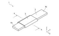
- FIG. 1 is a perspective view of a lead wire for a non-aqueous electrolyte battery according to an embodiment of the present disclosure.
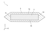
- FIG. 2 is an AA sectional view showing a cross section perpendicular to the central axis of the outer peripheral surface of the insulating film of the lead wire for a non-aqueous electrolyte battery according to an embodiment of the present disclosure.
- FIG. 3 is a schematic diagram showing a cross section perpendicular to the central axis of the outer peripheral surface of the insulating film in a region where the conductor of the lead wire for a non-aqueous electrolyte battery according to an embodiment of the present disclosure is covered with the insulating film.
- FIG. 1 is a perspective view of a lead wire for a non-aqueous electrolyte battery according to an embodiment of the present disclosure.
- FIG. 2 is an AA sectional view showing a cross section perpendicular to the central axis of the outer peripheral surface of the insulating film of the
- FIG. 4 is a partially enlarged sectional view showing a virtual region and its surroundings in the lead wire for a non-aqueous electrolyte battery shown in FIG.
- FIG. 5 is a partially enlarged sectional view showing a virtual area of the lead wire for a non-aqueous electrolyte battery in FIG. 4.
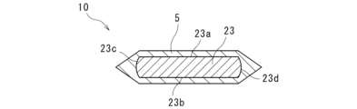
- FIG. 6 is a cross-sectional view perpendicular to the central axis of the outer peripheral surface of the insulating film, showing an example of a lead wire for a non-aqueous electrolyte battery including a conductor of another embodiment.
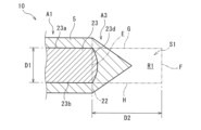
- FIG. 7 is a partially enlarged cross-sectional view showing a virtual region and its surroundings in the lead wire for a non-aqueous electrolyte battery in FIG.
- FIG. 8 is a partially enlarged sectional view showing a virtual area of the lead wire for a non-aqueous electrolyte battery in FIG. 7.
- FIG. FIG. 9 is a cross-sectional view perpendicular to the central axis of the outer peripheral surface of the insulating film, showing an example of a lead wire for a non-aqueous electrolyte battery including an insulating film of another embodiment.
- FIG. 10 is a cross-sectional view perpendicular to the central axis of the outer peripheral surface of the insulating film, showing an example of a lead wire for a non-aqueous electrolyte battery including an insulating film of another embodiment.
- FIG. 9 is a cross-sectional view perpendicular to the central axis of the outer peripheral surface of the insulating film, showing an example of a lead wire for a non-aqueous electrolyte battery including an insulating film of another embodiment.
- FIG. 11 is a cross-sectional view perpendicular to the central axis of the outer peripheral surface of the insulating film, showing an example of a lead wire for a non-aqueous electrolyte battery including an insulating film of another embodiment.
- FIG. 12 is a cross-sectional view perpendicular to the central axis of the outer peripheral surface of the insulating film, showing an example of a lead wire for a non-aqueous electrolyte battery including an insulating film of another embodiment.
- FIG. 13 is a perspective view showing an example of a non-aqueous electrolyte battery including the non-aqueous electrolyte battery lead wire of FIG.
- FIG. 14 is a longitudinal cross-sectional view of the nonaqueous electrolyte battery of FIG. 13.
- An object of the present disclosure is to provide a lead wire for a non-aqueous electrolyte battery that has excellent adhesion to a sealed container and can improve the productivity of the non-aqueous electrolyte battery.
- the lead wire for a non-aqueous electrolyte battery of the present disclosure includes: (1) A conductor and an insulating film covering a part of the circumferential surface of the conductor, wherein a region including the insulating film and the conductor covered with the insulating film is located along the central axis of the outer circumferential surface of the insulating film.
- the main body has a rectangular shape and a pair of protrusions protruding from both ends in the longitudinal direction of the main body, the pair of protrusions have a tapered shape, and in the cross-sectional view,
- the average thickness D1 of the conductor perpendicular to the longitudinal direction of the main body is 0.5 mm or more, and in the cross-sectional view, the conductor has the same length as the average thickness D1 provided on both ends of the main body in the longitudinal direction.
- the short side is a straight line with a length of D1
- the long sides are two straight lines whose length is twice the average thickness D1.
- the ratio of S2 to S1 is 30% or more.
- a non-aqueous electrolyte battery such as the above conventional technology
- the average thickness of a conductor whose cross section perpendicular to the central axis of the outer circumferential surface of the insulating film is rectangular is 0.5 mm or more
- the average thickness of this conductor is 0.5 mm or more.
- the thickness is much larger than the average thickness of the insulating film covering the conductor. Therefore, when viewed from the above-mentioned cross section, the insulating film is bent to follow the rectangular outer peripheral surface of the conductor, resulting in a step.
- the region including the insulating film and the conductor covered with the insulating film has a rectangular shape in a cross-sectional view perpendicular to the central axis of the outer peripheral surface of the insulating film. and a pair of protrusions protruding from both ends in the longitudinal direction of the main body, the pair of protrusions having a tapered shape, and the average thickness D1 of the conductor in the main body being 0.5 mm or more.
- the short side is a straight line provided on both ends of the main body in the longitudinal direction and has the same length as the average thickness D1, and 2 whose length is twice the average thickness D1 is defined as the short side.
- a rectangular virtual area whose long sides are the straight lines of the book is set outside both ends of the main body.
- the ratio of S2 to S1 is 30% or more.
- An insulating film is formed as shown. By forming the insulating film in this manner, the step difference can be reduced, and therefore, the adhesiveness when bonding the enclosure and the conductor through the insulating film by thermal fusion is improved.
- the adhesiveness can be improved without using the above-described complicated equipment or increasing the heat fusion time, so that the productivity of the non-aqueous electrolyte battery can be improved.
- the lead wire for a non-aqueous electrolyte battery has excellent adhesiveness to the enclosure and can improve the productivity of the non-aqueous electrolyte battery.
- Rectangle refers to a quadrilateral with all right angles.
- Average thickness means the average value of thickness measurements at five arbitrary points.
- the "W portion of the protrusion that is included in the virtual area” means a portion where the protrusion overlaps the virtual area in a cross-sectional view perpendicular to the central axis of the outer peripheral surface of the insulating film.
- the protruding part has a tapered shape
- the tip of the protrusion may have a sharp shape in the cross-sectional view, but may also be rounded with an arbitrary radius of curvature, or may be flat.
- the tapered shape includes, for example, a pyramid, a frustum, a hemisphere, a dome, a prism, and a cylinder.
- the tapered shape is not limited to one in which the contour line of the side surface of the protrusion is a straight line, and the contour line of the side surface may be a curved line or a curved line as long as the shape is tapered as a whole.
- the tapered shape may be a shape in which the area of the protrusion in the above-mentioned cross-sectional view monotonically decreases at a constant rate as the distance from the base end of the protrusion increases, or may decrease at an irregular rate. It may also have a decreasing shape.
- the resin which is the main component of the insulating film may have a melt flow rate of 1 g/10 minutes or more and 50 g/10 minutes or less at 230° C. and 2.16 kg.
- the resin, which is the main component of the insulating film has a melt flow rate of 1 g/10 minutes or more and 50 g/10 minutes or less at 230°C and 2.16 kg. It is possible to further enhance the adhesiveness of the material and improve the sealing performance.
- the above-mentioned "melt flow rate" is an index representing the fluidity of the resin.
- melt flow rate is measured using a melt indexer at a measurement temperature of 230°C and a weight of 2.16 kg, according to a method based on JIS-K7210-1:2014 (Method A: Mass measurement method). is the value.
- main component refers to a component having the highest content in terms of mass, for example, a component having a content of 50% by mass or more.
- the insulating film may have one or more insulating layers. Since the insulating film has one or more insulating layers, various functions can be provided depending on the purpose of the lead wire for a non-aqueous electrolyte battery.
- the ratio of the average thickness of the insulating film to the average thickness D1 may be 0.5 or less. Since the ratio of the average thickness of the insulating film to the average thickness D1 is 0.5 or less, the lead wire for a non-aqueous electrolyte battery can further enhance adhesiveness with the enclosure and improve sealing performance. can.
- the insulating film of the present disclosure is used in the lead wire for a non-aqueous electrolyte battery according to any one of (1) to (4) above.
- the lead wire for a non-aqueous electrolyte battery can improve adhesiveness with the enclosure and provide good sealing performance.
- the non-aqueous electrolyte battery of the present disclosure includes the lead wire for a non-aqueous electrolyte battery according to any one of (1) to (4) above.
- the non-aqueous electrolyte battery is provided with the non-aqueous electrolyte battery lead wire described above, the adhesiveness between the non-aqueous electrolyte battery lead wire and the enclosure in the non-aqueous electrolyte battery is excellent, and Increased productivity of water electrolyte batteries.
- FIG. 1 is a perspective view of a lead wire for a non-aqueous electrolyte battery according to an embodiment of the present disclosure.
- FIG. 2 is an AA sectional view showing a cross section perpendicular to the central axis of the outer peripheral surface of the insulating film 5 of the lead wire for a non-aqueous electrolyte battery according to an embodiment of the present disclosure.
- a lead wire 1 for a non-aqueous electrolyte battery according to the present embodiment shown in FIGS. 1 and 2 includes a flat conductor 3, a front surface portion 3a, a back surface portion 3b, and a pair of side surfaces 3c and 3d of the conductor 3.
- the flat conductor 3 has a rectangular cross section perpendicular to the central axis of the outer peripheral surface of the insulating film, and has a front surface portion 3a, a back surface portion 3b, and a pair of side surface portions 3c and 3d.
- the central axis direction of the outer peripheral surface of the insulating film is the Y-axis direction. Further, the current flowing through the conductor 3 flows in the positive direction or the negative direction on the Y-axis.
- the width direction of the conductor 3 orthogonal to the Y-axis and the Z-axis is defined as the X-axis direction.
- the thickness direction of the conductor 3 perpendicular to the Y-axis and the X-axis is defined as the Z-axis direction.
- FIG. 3 shows a cross section (A-A section FIG.
- the region including the insulating film 5 and the conductor 3 covered with the insulating film 5 shown in FIG. 3 includes the conductor 3 and the insulating film 5. More specifically, the region where the conductor 3 is covered with the insulating film 5 includes the rectangular main body portion A1 and both ends in the longitudinal direction of the main body portion A1 in a cross-sectional view perpendicular to the central axis of the outer peripheral surface of the insulating film 5. It has a pair of protrusions A2 and A3 that protrude in a tapered shape from the top.
- the protruding portion A2 protrudes in a tapered shape from one longitudinal end surface 21 of the main body portion A1
- the protruding portion A3 protrudes in a tapered shape from the other longitudinal end surface 22 of the main body portion A1.
- the region of the main body portion A1 has a rectangular shape.
- the conductor 3 in the non-aqueous electrolyte battery lead wire 1 has a rectangular cross section perpendicular to the central axis of the outer peripheral surface of the insulating film 5, that is, a cross section perpendicular to the current flow direction, and in this embodiment, the conductor 3 has a rectangular shape. be.
- the conductor 3 has a pair of front surface portions 3a and a back surface portion 3b facing each other, and a pair of side surface portions 3c and 3d facing each other and having a smaller area than the pair of front surface portions 3a and back surface portions 3b. .
- a pair of front surface portions 3a and a back surface portion 3b are parallel to each other, and a pair of side surface portions 3c and 3d are parallel to each other.
- the front surface portion 3a is perpendicular to the side surface portions 3c and 3d
- the back surface portion 3b is perpendicular to the side surface portions 3c and 3d.
- the conductor 3 is connected to an electrode of a non-aqueous electrolyte battery, etc.
- the material for forming the conductor 3 is not particularly limited as long as it is a material used as a conductor constituting lead wires for non-aqueous electrolyte batteries, such as aluminum, titanium, nickel, copper, aluminum alloy, titanium alloy, nickel alloy. Examples include metal materials such as copper alloys, and materials obtained by plating these metal materials with nickel, gold, etc.
- the material for forming the conductor 3 connected to the positive electrode of the nonaqueous electrolyte battery may be one that does not dissolve during discharge, and specifically may be aluminum, titanium, an aluminum alloy, or a titanium alloy.
- the material for forming the conductor 3 connected to the negative electrode may be nickel, copper, nickel alloy, copper alloy, nickel-plated copper, or gold-plated copper.
- the lower limit of the average thickness D1 of the conductor in the region of the main body portion A1 is 0.5 mm, may be 1.0 mm, may be 2.0 mm, or may be 3.0 mm. Since the average thickness D1 is equal to or larger than the lower limit, even though the conductor 3 which is likely to have a step difference in the insulation film as described above is used, the encapsulation container and the conductor 3 can be connected through the insulation film 5 as described above. Since the adhesiveness can be improved, the superiority of the lead wire 1 for a non-aqueous electrolyte battery increases.
- the upper limit of the average thickness D1 of the conductor 3 is not particularly limited, and may be appropriately set, for example, depending on the capacity of the nonaqueous electrolyte battery.
- the upper limit of the average thickness D1 may be 6.0 mm, or may be 5.0 mm.
- the average thickness D1 is less than the upper limit, there is a risk that the average thickness D1 becomes unnecessarily large compared to the capacity of the nonaqueous electrolyte battery to which the nonaqueous electrolyte battery lead wire 1 is applied. can be reduced.
- the insulating film 5 is used as an insulating film for a lead wire for a non-aqueous electrolyte battery.
- the insulating film 5 is laminated on the outer circumferential surface of the conductor 3 so as to cover at least a portion of the outer circumferential surface of the conductor 3 . More specifically, it is provided so as to cover the entire circumference of the conductor in a portion of the outer peripheral surface of the insulating film 5 in the direction along the central axis.
- the shape of the outer circumferential surface of the insulating film 5 is a rectangular main body and a pair of tapered shapes protruding from both longitudinal ends of the main body in a cross-sectional view perpendicular to the central axis of the outer circumferential surface of the insulating film 5. It has a protrusion.
- the main component of the insulating film 5 is a resin material that is easily melted at the heat-sealing temperature when the opening of the enclosure is heat-sealed (thermal fusion) and is difficult to be thermally deformed at temperatures higher than the operating temperature of the battery. It's okay.
- the heat sealing temperature can be freely designed according to the resin material, and the operating temperature of the battery is 80°C or lower for batteries that use an organic non-aqueous electrolyte, and 100°C or higher for all-solid-state batteries that do not use an organic non-aqueous electrolyte. is assumed.
- resin materials include thermoplastic resins and thermosetting resins having a melting point of 140° C. or higher.
- the insulating film 5 of the non-aqueous electrolyte battery lead wire may have one or more insulating layers. Since the insulating film 5 has one or more insulating layers, various functions can be provided depending on the purpose of the lead wire 1 for a non-aqueous electrolyte battery.
- Examples of the resin that is the main component of the insulating film 5 include olefin thermoplastic resin.
- the olefin thermoplastic resin include polypropylene, polyethylene, and derivatives thereof. Among these, polypropylene may be used, and random polypropylene having a melting point of 120° C. or more and 155° C. or less and an MFR of 3 g/10 minutes or more and 15 g/10 minutes or less may be used.
- the olefinic thermoplastic resin is random polypropylene, there is an advantage that it can sufficiently exhibit adhesiveness with the sealed container.
- the lower limit of the melt flow rate of the resin that is the main component of the insulating film 5 at 230° C. and 2.16 kg may be 1 g/10 minutes or 3 g/10 minutes.
- the upper limit of the melt flow rate may be 50 g/10 minutes or 15 g/10 minutes. Since the melt flow rate of the resin, which is the main component of the insulating film 5, at 230°C and 2.16 kg is 1 g/10 minutes or more and 50 g/10 minutes or less, the lead wire for the non-aqueous electrolyte battery can be It is possible to further enhance the adhesiveness of the material and improve the sealing performance.
- the insulating film may have, for example, one layer, two layers, or four or more layers.
- the main component of the first insulating layer is Alternatively, a non-crosslinked resin may be used.
- the main component of the second insulating layer may be a crosslinked resin or a non-crosslinked resin having a melting point 10° C. or more higher than that of the non-crosslinked resin that is the main component of the first insulating layer.
- the first insulating layer and the second insulating layer are made of the above-mentioned resin, the first insulating layer has high melt fluidity, and the adhesion between the first insulating layer and the conductor 3 becomes good, while the second insulating layer Since the layer is difficult to melt during heat sealing (thermal fusion), short circuit between the metal layer of the enclosure and the conductor 3 can be suppressed.
- the insulating film 5 may have three or more layers, and the main component of the outermost layer may be a non-crosslinked resin.
- the layer in contact with the conductor 3 in the insulating film 5 is the first insulating layer
- the layer in contact with the first insulating layer is the second insulating layer
- the layer in contact with the second insulating layer is the third insulating layer
- the main component of the third insulating layer may be a non-crosslinkable resin.
- the non-crosslinked resin with high melt flowability is easily filled into the gap between the metal layer of the sealed container and the conductor 3, and the sealing time can be shortened.
- the insulating film 5 may contain other known additives as long as the effects of the present disclosure are not impaired.
- known additives include antioxidants, flame retardants, tackifiers, lubricants, fillers, crystallization promoters, and colorants.
- the average thickness of the insulating film 5 in the area covered by the front surface portion 3a and the back surface portion 3b of the conductor 3 may be 100 ⁇ m or more and 500 ⁇ m or less, or 150 ⁇ m or more and 350 ⁇ m or less.
- the average thickness is within the above range, there is an advantage that the insulating film 5 has a sufficient insulating function and prevents moisture from penetrating inside the battery, which would deteriorate the inside of the battery.
- a pair of side surfaces 3c and 3d of the conductor 3 coincide with the base ends of the protrusion A2 and the protrusion A3.
- the length from the base end of the protrusion A2 and the protrusion A3 that protrude outward from the pair of side surfaces 3c and 3d of the conductor 3 (outward from both longitudinal ends of the main body A1) is 1 mm or more and 30 mm. or less, and may be 3 mm or more and 7 mm or less.
- the length from the base end of the protrusion A2 is the length between the base end of the protrusion A2 (the side surface portion 3c of the conductor 3) and the tip of the protrusion A2 that protrudes outward from the side surface portion 3c of the main body portion A1.
- This is the shortest connecting distance in the longitudinal direction
- the length from the base end of the protrusion A3 is the length between the base end of the protrusion A3 (the side surface portion 3d of the conductor 3) and the length of the protrusion A3 that protrudes outward from the side surface portion 3d. This is the shortest distance connecting the leading edge in the longitudinal direction of the main body portion A1.
- the upper limit of the ratio of the average thickness of the insulating film 5 to the average thickness D1 of the conductor 3 may be 0.5 or 0.3.
- the ratio of the average thickness of the insulating film 5 to the average thickness D1 may be 0.5 or less.
- the non-aqueous electrolyte battery lead wire 1 can further improve the adhesiveness with the enclosure and improve the sealing performance. You can improve.
- the lower limit of the ratio of the average thickness of the insulating film 5 to the average thickness D1 may be 0.1 or 0.2.
- the lead wire 1 for a non-aqueous electrolyte battery has a sufficient distance between the metal layer of the enclosure and the conductor 3. Insulating properties can be obtained.
- the main body portion A1 of the area including the insulating film 5 and the conductor 3 covered by the insulating film 5 in a cross-sectional view perpendicular to the central axis of the outer peripheral surface of the insulating film 5 The average thickness D1 of the conductor 3 in is 0.5 mm or more.
- the insulating film 5 is formed to satisfy the following area ratio.
- the short side is a straight line with the same length as the average thickness D1 provided on both longitudinal ends of the main body portion A1, and the length is the above average thickness.
- a rectangular virtual region R1 whose long sides are two straight lines that are twice the length D1 is set outside both ends of the main body.
- the virtual region R1 is a temporary region set so that the area of the protrusion in the insulating film 5 is optimized in the cross-sectional view.
- the ratio of the S2 to the S1 is 30% or more.
- the insulating film 5 is formed as shown in FIG. By forming the insulating film 5 in this way, the above-mentioned step difference can be reduced, so that the adhesiveness when bonding the enclosure and the conductor 3 through the insulating film by thermal fusion is improved.
- the adhesiveness can be improved without using the above-described complicated equipment or increasing the heat fusion time, so that the productivity of the non-aqueous electrolyte battery can be improved.
- the lead wire for a non-aqueous electrolyte battery has excellent adhesiveness to the enclosure and can improve the productivity of the non-aqueous electrolyte battery.
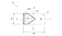
- FIGS. 4 and 5 are partially enlarged sectional views showing a virtual region R1 in the lead wire 1 for a non-aqueous electrolyte battery.
- a main body part on the outside of the longitudinal side surface of the main body part A1.
- a short side E provided on the side surface in the longitudinal direction of A1
- a rectangular virtual region R1 is provided.
- the virtual region R1 shown in FIGS. 4 and 5 has one side E that coincides with the side surface portion 3d, is parallel to the side surface portion 3d, and has a distance D2 from the side surface portion 3d that is twice the above average thickness D1. It is defined by one side F and two sides (side G and side H) extending outward from the ends of the pair of front surface portion 3a and back surface portion 3b of the conductor 3, respectively. That is, the shape of the virtual region R1 is a rectangle (rectangle) formed by sides E, F, G, and H.
- the short side E coincides with the side surface portion 3c of the conductor 3.
- the area of the rectangular virtual region R1 is S1
- the area of the W portion 51 that is included in the virtual region R1 in the protrusion A3 is S2
- the ratio of S2 is 30% or more.
- the above-mentioned insulating film 5 covers the conductor 3. Since the level difference caused by the shape of the conductor 3 can be reduced, the adhesiveness when bonding the enclosure and the conductor 3 via the insulating film 5 by thermal fusion is improved. This reduces the occurrence of gaps. In addition, the adhesiveness can be improved without using the above-described complicated equipment or increasing the heat fusion time, so that the productivity of the non-aqueous electrolyte battery can be improved.
- the lower limit of S2/S1 is 30% as described above, and in addition, from the viewpoint of further improving the adhesiveness, it may be 50% or 60%.
- the upper limit of S2/S1 may be, for example, 80% or 70%.
- the W portion which is a portion included in the virtual region R1, in the protrusion portion A2 with respect to the area S1 of the virtual region R1, as in the above-mentioned side surface portion 3d.
- the insulating film 5 is formed such that the ratio of the area S2 of the protrusion 51 is 30% or more, and the protrusion A2 has the same effect as the protrusion A3.
- the shape of the outer periphery of the insulating film 5 in a cross-sectional view perpendicular to the central axis of the outer peripheral surface of the insulating film 5 is not particularly limited as long as it satisfies the above area ratio.
- the shape of the outer periphery of the insulating film 5 that satisfies the above area ratio is, for example, a tapered shape in which both longitudinal ends of a rectangular body protrude outward when viewed in a cross section perpendicular to the central axis of the outer periphery of the insulating film 5.
- An example is a form formed into a shape.
- both ends of the insulating film 5 in a tapered shape toward the outside in the longitudinal direction in the cross-sectional view, it is possible to easily set S2/S1 within the above range.
- a step may be formed to the extent that adhesiveness with the enclosure is not impaired.
- the shape of the outer circumference of the insulating film 5 in a cross-sectional view perpendicular to the central axis of the outer circumferential surface of the insulating film 5 is as shown in FIG.
- a rectangular main body A1 and a pair of protrusions A2 that protrude outward from both longitudinal ends of the main body A1 in a tapered shape It has a shape that includes the projection part A3 and the projection part A3.
- the protrusion A2 and the protrusion A3 have linear tapered shapes toward the central axes of the protrusion A2 and the protrusion A3, respectively, which are parallel to the longitudinal direction of the main body portion A1. More specifically, in the above-mentioned cross-sectional view, the protruding portion A2 and the protruding portion A3 are, as a whole, the 2nd hypotenuse of a triangle having an apex facing outward in the longitudinal direction of the main body portion A1 (for example, the 2nd hypotenuse of an isosceles triangle). is formed to constitute.
- the shape of the conductor 3 of the lead wire 1 for a non-aqueous electrolyte battery is not particularly limited, and for example, in a cross-sectional view perpendicular to the central axis of the outer peripheral surface of the insulating film, it is rectangular, approximately rectangular, or rectangular from both ends in the longitudinal direction. Examples include a shape that projects outward in a tapered shape. Among these, the shape of the conductor 3 is rectangular like the conductor 3 shown in FIG. It may be a substantially rectangular shape that curves outward. Since the shape of the conductor of the lead wire for a non-aqueous electrolyte battery is rectangular or substantially rectangular, productivity is high and costs can be reduced.
- the shape of the conductor is rectangular or approximately rectangular, thereby increasing the volume ratio of the insulating film. be able to.
- the gap between the conductor and the enclosure is easily filled when the enclosure and the lead wire for the nonaqueous electrolyte battery are crimped, and the adhesiveness between the conductor and the enclosure in the present invention is improved. This effect can be more effectively achieved.
- the ratio of S2 to S1 is 30% or more.
- FIGS. 7 and 8 are partially enlarged sectional views showing a virtual region R1 in the non-aqueous electrolyte battery lead wire 10 shown in FIG. 6.
- FIG. As shown in FIGS. 7 and 8, in a cross-sectional view perpendicular to the central axis of the outer peripheral surface of the insulating film 5 in a region including the insulating film 5 and the conductor 23 covered by the insulating film 5, the longitudinal direction of the main body portion A1 is On the outside of the side surface in the longitudinal direction, a short side E overlaps with the side surface in the longitudinal direction of the main body A1, a short side F parallel to this short side E, and two pieces having a length twice the above average thickness D1.
- a rectangular virtual region R1 whose long sides are straight lines G and H is provided.
- the side surface portion of the main body portion A1 in the longitudinal direction does not coincide with the side surface portion 23d of the conductor 23. That is, in the non-aqueous electrolyte lead wire 10, the side E of the virtual region R1 does not coincide with the side surface portion 23d of the conductor 23.
- the area of the rectangular virtual region R1 is S1
- the area of the W portion 51 that is included in the virtual region R1 in the protrusion A3 is S2
- the ratio of S2 is 30% or more.
- the lead wire 20 for a non-aqueous electrolyte battery shown in FIG. In a cross-sectional view perpendicular to the central axis of the surface, it has a rectangular main body and a pair of protrusions protruding from both ends of the main body in the longitudinal direction.
- the protruding portion has a tapered shape in the cross-sectional view, and each protruding portion has a shape that protrudes in an arc shape toward a center line of the protruding portion parallel to the longitudinal direction of the main body in the cross-sectional view.
- the above-mentioned arc shape also includes an elliptical arc shape.
- the rectangular virtual region R1 is defined as both ends of the main body (the side surface 3c of the conductor 3 and When set outside the side surface portion 3d), when the area of the rectangular virtual area is S1 and the area of the W portion of the protrusion included in the virtual area is S2, the ratio of S2 to S1 is
- the insulating film 15 is formed so that it is 30% or more.
- the main body has a shape that includes a pair of tapered protrusions that protrude from both ends of the main body in the longitudinal direction. Similar to the insulating film 5 in FIG. 2, the protrusions are parallel to the longitudinal direction of the main body from both longitudinal ends of the main body in a cross-sectional view perpendicular to the central axis of the outer peripheral surface of the insulating film 25.
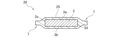
- a linear tapered shape is formed toward the center line of the main body, and a protrusion 7 is formed that further projects in the longitudinal direction of the main body from the tip of this linear tapered shape.
- a convex portion may be formed to further protrude from the tip of the arc-shaped protruding portion as shown in the protruding portion of the insulating film 15 in FIG. 9, as described above.
- the rectangular virtual region R1 is defined as both ends of the main body (the side surface 3c of the conductor 3 and When set outside the side surface portion 3d), when the area of the rectangular virtual area is S1 and the area of the W portion of the protrusion included in the virtual area is S2, the ratio of S2 to S1 is The insulating film 25 is formed so that it is 30% or more.
- the main body has a shape that includes a pair of protrusions that protrude from both end faces in the longitudinal direction of the main body.
- the protruding parts protrude from both ends of the upper surface of the main body close to the front surface 3a of the conductor 3 so as to be linearly inclined toward a straight line extended from the bottom surface of the main body close to the back surface 3b.
- a pair of tapered shapes are formed.
- each of the pair of protrusions has a base that is a straight line extended from the bottom surface of the main body close to the back surface 3b of the conductor 3, and a straight line extending from the bottom surface of the main body close to the front surface 3a of the conductor 3. It is formed to form a right triangle whose hypotenuse is a surface that slopes linearly from both ends toward the outside and the base. Further, the bottom surface of the insulating film 35 adjacent to the back surface portion 3b is formed in a straight line toward the outside of the side surface portions 3c and 3d of the conductor 3. Note that the inclined surface of the insulating film 35 at the protrusion may be formed to have a curved slope such as an arc shape or a curved shape.
- the rectangular virtual region R1 is defined at both ends of the main body (the side surface 3c of the conductor 3 and When set outside the side surface portion 3d), when the area of the rectangular virtual area is S1 and the area of the W portion of the protrusion included in the virtual area is S2, the ratio of S2 to S1 is
- the insulating film 35 is formed so that the thickness is 30% or more.
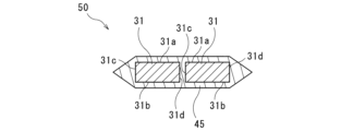
- the lead wire 50 for a non-aqueous electrolyte battery of another embodiment shown in FIG. This is the same shape as the outer periphery of the insulating film 5 shown.
- a plurality of (two in this embodiment) conductors 31 are connected to each other in the longitudinal direction of the main body.
- An insulating film 45 is formed to cover the plurality of conductors 31, which are arranged in parallel with an interval between them.
- Each conductor 31 has a front surface portion 31a, a back surface portion 31b, and a pair of side surface portions 31c and 31d.
- the outermost side surface of the plurality of conductors 31 is a part of the short side of the virtual area (not shown).
- the lead wire 50 for a non-aqueous electrolyte battery extends from both ends of the front surface portion 31a and the back surface portion 31b located at the outermost ends of the two conductors 31, and has a length equal to the average thickness D1 of the conductor 31.
- the two straight lines, which are twice as long as are the long sides of the virtual area (not shown).
- the gap between the two conductors 31 is filled with the insulating film 45.
- a pair of protrusions having shapes as shown in FIGS. may be provided.
- the rectangular virtual region R1 is defined at both ends of the main body (the lateralmost part of the two conductors 31) in a cross-sectional view perpendicular to the central axis of the outer circumferential surface of the insulating film 45.
- the area of the rectangular virtual area is S1
- the virtual area in the protrusion is When the area of the W portion included in the region is S2, the insulating film 45 is formed such that the ratio of S2 to S1 is 30% or more.
- the method for manufacturing the insulating film of the present disclosure is not particularly limited.
- a resin composition for forming an insulating layer containing the respective resin components and additives of each insulating layer is mixed using a known mixing device such as an open roll, a pressure kneader, a single-screw mixer, a twin-screw mixer, or the like.
- a known mixing device such as an open roll, a pressure kneader, a single-screw mixer, a twin-screw mixer, or the like.
- each film-like insulating layer can be produced by extrusion molding such as T-die molding or inflation molding.
- each insulating layer is overlapped and thermally laminated using a hot roll and bonded together.
- an inflation method using coextrusion or a T-die method can be used.
- an extrusion lamination method can be used in which a molten resin is laminated on a film formed in a single layer.
- the insulating layer can be produced not only by extrusion molding but also by injection molding. In injection molding, the peripheral surface of the conductor can be covered by injecting resin after the conductor is mounted in a mold, and two-color molding can be used when forming multiple layers.
- the lead wire for the non-aqueous electrolyte battery can improve adhesiveness with the enclosure and provide good sealing properties.
- the lead wire 1 for a non-aqueous electrolyte battery is not particularly limited, and can be manufactured by a known method.
- a desired insulating film is formed. It can be manufactured by sandwiching it between known molds according to the shape of the outer peripheral surface of No. 5 and heating the molds with a known heating device.
- the insulating sheet an insulating sheet made of the material for forming the insulating film 5 described above can be used, and a commercially available product can also be used as this insulating sheet.
- the lead wire 1 for a non-aqueous electrolyte battery can be produced by placing a conductor 3 as shown in FIG.
- the conductor 3 is placed in a mold, and the insulating film 5 can be formed by placing the conductor 3 in the gap between the conductor 3 and the mold and heating and molten granular forming material for forming the insulating film 5. .
- the lead wire 1 for a non-aqueous electrolyte battery has excellent adhesiveness to the enclosure and can improve productivity of the non-aqueous electrolyte battery.
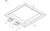
- the nonaqueous electrolyte battery 100 includes the nonaqueous electrolyte battery lead wire 1 described above.
- Examples of the non-aqueous electrolyte battery include secondary batteries such as lithium ion batteries, and the non-aqueous electrolyte included in this secondary battery may be an organic non-aqueous electrolyte or a solid non-aqueous electrolyte.
- the non-aqueous electrolyte battery 100 includes various secondary batteries such as all-solid-state batteries.
- a non-aqueous electrolyte battery (secondary battery) 100 shown in FIGS. 13 and 14 includes a plate-shaped positive electrode, a plate-shaped negative electrode, a non-aqueous electrolyte (for example, a non-aqueous electrolyte), an enclosure 11, and a non-aqueous A lead wire 1 for an electrolyte battery is provided.
- the lead wire 1 for a non-aqueous electrolyte battery is the aforementioned lead wire for a non-aqueous electrolyte battery.
- the lead wire 1 for non-aqueous electrolyte batteries includes the other insulating films 15, 25, and the insulating films described above. 35, another insulating film such as an insulating film 45 may be provided.
- a positive electrode and a negative electrode are stacked with a separator in between to form a stacked electrode group (stacked electrode group).
- This laminated electrode group and the non-aqueous electrolyte are housed in an enclosure 11 in a sealed state. In this enclosure 11, the laminated electrode group is immersed in the non-aqueous electrolyte.
- the enclosure 11 is formed from a laminated film, as will be described later.
- the sealing portion 13 around the two laminated films or one folded laminated film is heat-sealed, resulting in a sealed state.
- One non-aqueous electrolyte battery lead wire 1 is arranged so that one end 4a of the conductor 3 is exposed from the enclosure 11 and the other end 4b of the conductor 3 is connected to the positive electrode inside the enclosure 11. There is.
- the other non-aqueous electrolyte battery lead wire 1 is arranged so that one end 4a of the conductor 3 is exposed from the enclosure 11 and the other end 4b of the conductor 3 is connected to the negative electrode inside the enclosure 11. There is.
- the positive electrode and negative electrode are typically laminates in which an active material layer containing an active material is laminated on the surface of a current collector such as metal foil.
- the shape of the positive electrode and the negative electrode is usually plate-like, but may be in a shape other than plate-like.
- the separator is usually an insulating and porous sheet. This separator is impregnated with a non-aqueous electrolyte.
- non-aqueous electrolyte a non-aqueous solvent in which a non-aqueous electrolyte salt is dissolved in a non-aqueous solvent can be used.
- the enclosure 11 includes, for example, a metal base material, a resin layer laminated on the inside of the base material, and an outer layer laminated on the outside of the base material. That is, as the enclosure container 11, for example, a laminated film in which a resin layer, a base material, and an outer layer are laminated in this order can be used. Further, as described above, the enclosure container 11 is a container that contains the positive electrode, the negative electrode, the separator, and the non-aqueous electrolyte in a sealed state.
- the above-mentioned base material is in the form of a film, and is usually a metal foil. That is, the base material has metal as a main component. Examples of this metal include aluminum, copper, and stainless steel. Although the base material is substantially made of metal, it may contain additives other than metal.
- the resin layer is directly laminated inside the base material.
- the resin layer include a layer containing a crosslinked fluororesin.
- the resin layer may contain other optional components in addition to this fluororesin.
- the resin layer is a heat-fusible layer having heat-fusibility.
- the fluororesin include known fluororesins, such as crosslinked fluororesins.
- the outer layer has a function as a protective layer that protects the outside of the base material.
- the outer layer usually contains resin as a main component. Examples of the resin forming this outer layer include polyethylene terephthalate (PET) and polyamide. Further, as the resin forming the outer layer, for example, a resin having a melting point higher than the melting point of the crosslinked fluororesin contained in the resin layer can be used.
- an internal connection lead wire 14 (not shown) is connected to the other end 4b of the conductor 3 of the positive electrode non-aqueous electrolyte battery lead wire 1 through a solder portion 9. Connected to positive pole.
- an internal connection lead wire 14 is connected to the other end 4b of the conductor 3 of the negative electrode non-aqueous electrolyte battery lead wire 1 through the solder portion 9, and by this internal connection lead wire 14, Connected to a negative electrode (not shown).
- one end portion of the non-aqueous electrolyte battery lead wire 1, that is, one end portion 4a of the conductor 3, is arranged in a state exposed from the enclosure 11. Then, the non-aqueous electrolyte battery 100 is sealed with the enclosure container 11. Specifically, the non-aqueous electrolyte battery lead wire 1 is arranged so that the resin layer of the enclosure 11 and the insulating film 5 of the non-aqueous electrolyte battery lead wire 1 are in direct contact.
- the resin layers in the seal portion 13 of the enclosure 11 are connected to each other, and the resin layer of the enclosure 11 and the lead wire 1 for a non-aqueous electrolyte battery are connected to each other.
- the insulating film 5 is thermally fused. Thereby, the positive electrode, negative electrode, and separator, which are the laminated electrode group immersed in the non-aqueous electrolyte, can be sealed in the enclosure 11.
- the nonaqueous electrolyte battery 100 of this embodiment includes the nonaqueous electrolyte battery lead wire 1 of this embodiment described above, productivity is improved.
- the X-axis direction which is the width direction of the conductor
- the Y-axis direction which is perpendicular to the width direction of the conductor
- the present invention is not limited to this.
- the X-axis direction which is the width direction of the conductor
- the Y-axis direction which is perpendicular to the width direction of the conductor
- the length in the X-axis direction, which is the width direction of the conductor may be the same as the length in the Y-axis direction, which is perpendicular to the width direction of the conductor.
- the average thickness D1 of the conductor in the main body is 0.5 mm or more
- the area of the virtual area is S1
- W is a portion of the protrusion included in the virtual area.
- Test No. 3 has a ratio of S2 to S1 of 30% or more. 2 and test no.
- Sample No. 4 was sealed with the enclosure without any gaps, and the sealing performance was good.
- test No. 1 in which the ratio of S2 to S1 was less than 30%. 1 and test no. In No. 3, voids were observed and the sealing performance was poor.
- the above results showed that the lead wire for a non-aqueous electrolyte battery has excellent adhesiveness to the enclosure.
- the lead wire for a non-aqueous electrolyte battery of the present disclosure has excellent adhesion to an enclosure and can improve the productivity of a non-aqueous electrolyte battery, so it can be suitably used for power storage elements such as secondary batteries and capacitors.
Landscapes
- Chemical & Material Sciences (AREA)
- Chemical Kinetics & Catalysis (AREA)
- Electrochemistry (AREA)
- General Chemical & Material Sciences (AREA)
- Sealing Battery Cases Or Jackets (AREA)
- Connection Of Batteries Or Terminals (AREA)
Abstract
本開示の非水電解質電池用リード線は、導体と、上記導体の周面の一部を被覆する絶縁膜とを備え、上記絶縁膜と上記絶縁膜により被覆された導体とを含む領域が、上記絶縁膜の外周面の中心軸と垂直な断面視で、矩形状の本体部と上記本体部の長手方向両端部から突出する一対の突出部とを有し、上記一対の突出部が先細り形状を有し、上記断面視において、上記本体部の長手方向と垂直な上記導体の平均厚さD1が0.5mm以上であり、上記断面視において、上記本体部の長手方向の両端部上に設けられる上記平均厚さD1と同じ長さの直線を短辺とし、長さが上記平均厚さD1の2倍である2本の直線を長辺とする矩形の仮想領域を上記本体部の両端部の外側に設けた場合に、上記仮想領域の面積をS1とし、かつ上記突出部のうち上記仮想領域に含まれる部分であるW部分の面積をS2とするとき、上記S1に対する上記S2の比率が30%以上である。
Description
本開示は、非水電解質電池用リード線、絶縁膜および非水電解質電池に関する。
本出願は、2022年5月2日出願の日本出願第2022-076338号に基づく優先権を主張し、上記日本出願に記載された全ての記載内容を援用するものである。
本出願は、2022年5月2日出願の日本出願第2022-076338号に基づく優先権を主張し、上記日本出願に記載された全ての記載内容を援用するものである。
電子機器の小型化、軽量化に伴って、これらの機器に使用される電池、コンデンサなどの電気部品についても小型化、軽量化が求められている。このため、例えば、袋体を封入容器として用い、その内部に非水電解質(例えば非水電解液)、正極、および負極を封入してなる非水電解質電池が採用されている。
封入容器には非水電解質やガスの透過、外側からの水分の浸入を防止する性質が求められる。このため、アルミニウム箔などの金属層を樹脂で被覆したラミネートフィルムが封入容器の材料として用いられ、2枚のラミネートフィルムの端部を熱融着して封入容器が形成される。
封入容器の一端は開口部とされ、この封入容器の内部に非水電解質、正極板、負極板、セパレータ等が封入される。さらに、正極板および負極板にその一端が接続されたリード導体は、封入容器の内部から外部に向けて配置され、最後に開口部がヒートシール(熱融着)される。これにより、封入容器の開口部が閉じられると共に、封入容器と導体とが接着されて開口部が封止される。この最後に熱融着される部分をシール部と呼ぶ。
導体のシール部に対応する部分には絶縁膜が被覆されており、絶縁膜と導体とを備えたものが非水電解質電池用リード線(タブリード)と呼ばれている。封入容器と導体とは絶縁膜を介して接着(熱融着)される。従って、絶縁膜には、封入容器の金属層と導体との短絡を発生させることなく導体と封入容器との接着性を維持することができるという特性が求められる。
また、封止直後の接着性が充分であっても、長期使用により、シール部を透過した水分が封入容器の内部に封入された非水電解質と反応して、フッ化水素酸が発生し、フッ化水素酸がリード導体(金属)を腐食し、導体と絶縁膜との界面で剥がれが生じるという問題がある。
このような問題を解決する方法として、例えば特許文献1には、ポリアクリル酸とポリアクリル酸アミドを含む樹脂成分と金属塩とを含む処理液がリード導体に塗布されることで複合皮膜層が形成され、この複合皮膜層の外側に絶縁体を備える非水電解質電池用リード線が開示されている。
本開示の非水電解質電池用リード線は、導体と、上記導体の周面の一部を被覆する絶縁膜とを備え、上記絶縁膜と上記絶縁膜により被覆された導体とを含む領域が、上記絶縁膜の外周面の中心軸と垂直な断面視で、矩形状の本体部と上記本体部の長手方向両端部から突出する一対の突出部とを有し、上記一対の突出部が先細り形状を有し、上記断面視において、上記本体部の長手方向と垂直な上記導体の平均厚さD1が0.5mm以上であり、上記断面視において、上記本体部の長手方向の両端部上に設けられる上記平均厚さD1と同じ長さの直線を短辺とし、長さが上記平均厚さD1の2倍である2本の直線を長辺とする矩形の仮想領域を上記本体部の両端部の外側に設けた場合に、上記仮想領域の面積をS1とし、かつ上記突出部のうち上記仮想領域に含まれる部分であるW部分の面積をS2とするとき、上記S1に対する上記S2の比率が30%以上である。
[本開示が解決しようとする課題]
近年、非水電解質電池の容量が従来よりも増大されており、それに応じて導体の厚さが大きくされる傾向にある。しかし、上記特許文献1に記載されたような非水電解質電池用リードでは、導体の厚さが大きい場合に上記封入容器と上記絶縁膜との間の接着性が不十分になるおそれがある。このように接着性が不十分であると、接着性を高めるために複雑な装置が必要とされる、熱融着の長時間化が必要とされるといったように、非水電解質電池を生産する際の生産性の低下に繋がるおそれがある。
近年、非水電解質電池の容量が従来よりも増大されており、それに応じて導体の厚さが大きくされる傾向にある。しかし、上記特許文献1に記載されたような非水電解質電池用リードでは、導体の厚さが大きい場合に上記封入容器と上記絶縁膜との間の接着性が不十分になるおそれがある。このように接着性が不十分であると、接着性を高めるために複雑な装置が必要とされる、熱融着の長時間化が必要とされるといったように、非水電解質電池を生産する際の生産性の低下に繋がるおそれがある。
本開示は、封入容器との接着性に優れ、非水電解質電池の生産性を向上できる非水電解質電池用リード線を提供することを目的とする。
[本開示の効果]
本開示によれば、封入容器との接着性に優れ、非水電解質電池の生産性を向上可能な非水電解質電池用リード線を提供できる。
本開示によれば、封入容器との接着性に優れ、非水電解質電池の生産性を向上可能な非水電解質電池用リード線を提供できる。
[本開示の実施形態の説明]
最初に本開示の実施形態を列挙して説明する。
最初に本開示の実施形態を列挙して説明する。
本開示の非水電解質電池用リード線は、
(1)導体と、上記導体の周面の一部を被覆する絶縁膜とを備え、上記絶縁膜と上記絶縁膜により被覆された導体とを含む領域が、上記絶縁膜の外周面の中心軸と垂直な断面視で、矩形状の本体部と上記本体部の長手方向両端部から突出する一対の突出部とを有し、上記一対の突出部が先細り形状を有し、上記断面視において、上記本体部の長手方向と垂直な上記導体の平均厚さD1が0.5mm以上であり、上記断面視において、上記本体部の長手方向の両端部上に設けられる上記平均厚さD1と同じ長さの直線を短辺とし、長さが上記平均厚さD1の2倍である2本の直線を長辺とする矩形の仮想領域を上記本体部の両端部の外側に設けた場合に、上記仮想領域の面積をS1とし、かつ上記突出部のうち上記仮想領域に含まれる部分であるW部分の面積をS2とするとき、上記S1に対する上記S2の比率が30%以上である。
(1)導体と、上記導体の周面の一部を被覆する絶縁膜とを備え、上記絶縁膜と上記絶縁膜により被覆された導体とを含む領域が、上記絶縁膜の外周面の中心軸と垂直な断面視で、矩形状の本体部と上記本体部の長手方向両端部から突出する一対の突出部とを有し、上記一対の突出部が先細り形状を有し、上記断面視において、上記本体部の長手方向と垂直な上記導体の平均厚さD1が0.5mm以上であり、上記断面視において、上記本体部の長手方向の両端部上に設けられる上記平均厚さD1と同じ長さの直線を短辺とし、長さが上記平均厚さD1の2倍である2本の直線を長辺とする矩形の仮想領域を上記本体部の両端部の外側に設けた場合に、上記仮想領域の面積をS1とし、かつ上記突出部のうち上記仮想領域に含まれる部分であるW部分の面積をS2とするとき、上記S1に対する上記S2の比率が30%以上である。
上記従来技術のような非水電解質電池では、絶縁膜の外周面の中心軸と垂直な断面が矩形状である導体における平均厚さが0.5mm以上の大きさの場合、この導体の平均厚さは導体を覆う絶縁膜の平均厚さよりもはるかに大きくなる。このため、上記断面で視たとき、導体の矩形状の外周面に追従して絶縁膜が屈曲して段差が生じることになる。その結果、絶縁膜を介して封入容器と導体とを熱融着によって接着する際、この段差に起因して封入容器と導体との間の接着性が低下し、隙間が生じるおそれがある。この接着性の低下を解消すべく、封入容器を上記段差に追従させるよう複雑な装置を用いる、熱融着の時間を長くするといった方策が考えられる。しかし、このような方策を用いる場合、非水電解質電池の生産性の低下に繋がるおそれがある。
これに対し、当該非水電解質電池用リード線では、上記絶縁膜と上記絶縁膜により被覆された導体とを含む領域が、上記絶縁膜の外周面の中心軸と垂直な断面視で、矩形状の本体部と上記本体部の長手方向両端側から突出する一対の突出部を有し、上記一対の突出部が先細り形状を有し、本体部における導体の平均厚さD1が0.5mm以上である。そして、上記断面視において、上記本体部の長手方向の両端部上に設けられる上記平均厚さD1と同じ長さの直線を短辺とし、長さが上記平均厚さD1の2倍である2本の直線を長辺とする矩形の仮想領域を上記本体部の両端部の外側に設定する。この場合に、上記仮想領域の面積をS1とし、かつ上記突出部のうち上記仮想領域に含まれる部分であるW部分の面積をS2とするとき、上記S1に対する上記S2の比率が30%以上であるように絶縁膜が形成されている。このように絶縁膜が形成されることで、上記段差を小さくすることができるため、絶縁膜を介して封入容器と導体とを熱融着によって接着する際の接着性が高められる。これにより、隙間の発生が低減される。加えて、上述したような複雑な装置を用いたり、熱融着の時間を長くしたりしなくても上記接着性が高められるため、非水電解質電池の生産性を高めることができる。このように、当該非水電解質電池用リード線は、封入容器との接着性に優れ、非水電解質電池の生産性を向上できる。
「矩形」とは、全ての角が直角である四辺形をいう。「平均厚さ」とは、任意の5点での厚さの測定値の平均値を意味する。「突出部のうち仮想領域に含まれる部分であるW部分」とは、絶縁膜の外周面の中心軸と垂直な断面視で、上記突出部が上記仮想領域と重なる部分を意味する。
「突出部が先細り形状を有し」とは、絶縁膜の外周面の中心軸と垂直な断面視で突出部の基端から先端に向かうにつれて縮径する、すなわち幅が狭くなる形状であればよい。突出部の先端は、上記断面視で尖鋭形状でもよいが、任意の曲率半径を有する丸みを帯びていてもよく、平坦であってもよい。先細り形状には、例えば錐体、錘台、半球状、ドーム状、角柱、円柱が含まれる。また、先細り形状は、突出部の側面の輪郭線が直線のものに限定されず、全体として先細り形状であれば、側面の輪郭線が曲線や屈曲線であってもよい。さらに、先細り形状は、突出部の上記断面視における面積が、突出部の基端からの距離の増加に応じ、一定の割合で単調減少している形状であってもよく、変則的な割合で減少している形状であってもよい。
(2)上記(1)において、上記絶縁膜の主成分である樹脂の230℃、2.16kgにおけるメルトフローレートが1g/10分以上50g/10分以下であってもよい。上記絶縁膜の主成分である樹脂の230℃、2.16kgにおけるメルトフローレートが1g/10分以上50g/10分以下であることで、当該非水電解質電池用リード線においては、封入容器との接着性をより高め、封止性を向上できる。上記「メルトフローレート」は、樹脂の流動性を表す指標である。上記メルトフローレート(MFR)は、JIS-K7210-1:2014(A法:質量測定法)に準拠した方法により、測定温度230℃、加重2.16kgをかけ、メルトインデクサーを用いて測定される値である。また、本開示において「主成分」とは、質量換算で最も含有量の多い成分を意味し、例えば含有量が50質量%以上の成分を意味する。
(3)上記(1)または(2)において、上記絶縁膜が1または複数の絶縁層を有していてもよい。上記絶縁膜が1または複数の絶縁層を有することで、当該非水電解質電池用リード線の目的に応じて種々の機能を付与することができる。
(4)上記(1)から(3)のいずれかにおいて、上記平均厚さD1に対する上記絶縁膜の平均厚さの比が0.5以下であってもよい。上記平均厚さD1に対する上記絶縁膜の平均厚さの比が0.5以下であることで、当該非水電解質電池用リード線は、封入容器との接着性をより高めて封止性を向上できる。
(5)また、本開示の絶縁膜は、上述の(1)から(4)のいずれかに記載の非水電解質電池用リード線に用いられる。当該非水電解質電池用リード線は当該絶縁膜を用いることで、封入容器との接着性を高めて良好な封止性を付与することができる。
(6)また、本開示の非水電解質電池は、上述の(1)から(4)のいずれかに記載の非水電解質電池用リード線を備える。
当該非水電解質電池が上述した当該非水電解質電池用リード線を備えることによって、当該非水電解質電池における当該非水電解質電池用リード線と封入容器との接着性が優れており、かつ当該非水電解質電池の生産性が高まる。
[本開示の実施形態の詳細]
以下、本開示の各実施形態に係る非水電解質電池用リード線、絶縁膜および非水電解質電池について詳説する。
以下、本開示の各実施形態に係る非水電解質電池用リード線、絶縁膜および非水電解質電池について詳説する。
<非水電解質電池用リード線>
図1は、本開示の一実施形態に係る非水電解質電池用リード線の斜視図である。図2は、本開示の一実施形態に係る非水電解質電池用リード線の絶縁膜5の外周面の中心軸と垂直な断面を示すA-A断面図である。図1および図2に示す本実施形態の非水電解質電池用リード線1は、平板状の導体3と、上記導体3の表面部3a、裏面部3bおよび一対の側面部3cおよび側面部3dの一部を被覆するように積層される絶縁膜5とを備える。平板状の導体3は、絶縁膜の外周面の中心軸と垂直な断面が矩形状であり、表面部3a、裏面部3b、および一対の側面部3cおよび側面部3dを有する。なお、図1および図2では、絶縁膜の外周面の中心軸方向(本実施形態においては、導体3の長手方向)をY軸方向とする。また、導体3を流れる電流は、Y軸における正の方向または負の方向に流れる。そして、本実施形態においては、Y軸およびZ軸に直交する導体3の幅方向をX軸方向とする。Y軸およびX軸に直交する導体3の厚さ方向をZ軸方向とする。
図1は、本開示の一実施形態に係る非水電解質電池用リード線の斜視図である。図2は、本開示の一実施形態に係る非水電解質電池用リード線の絶縁膜5の外周面の中心軸と垂直な断面を示すA-A断面図である。図1および図2に示す本実施形態の非水電解質電池用リード線1は、平板状の導体3と、上記導体3の表面部3a、裏面部3bおよび一対の側面部3cおよび側面部3dの一部を被覆するように積層される絶縁膜5とを備える。平板状の導体3は、絶縁膜の外周面の中心軸と垂直な断面が矩形状であり、表面部3a、裏面部3b、および一対の側面部3cおよび側面部3dを有する。なお、図1および図2では、絶縁膜の外周面の中心軸方向(本実施形態においては、導体3の長手方向)をY軸方向とする。また、導体3を流れる電流は、Y軸における正の方向または負の方向に流れる。そして、本実施形態においては、Y軸およびZ軸に直交する導体3の幅方向をX軸方向とする。Y軸およびX軸に直交する導体3の厚さ方向をZ軸方向とする。
図3は、当該非水電解質電池用リード線1における絶縁膜5と絶縁膜5により被覆された導体3とを含む領域の絶縁膜5の外周面の中心軸と垂直な断面(A-A断面図)を示す模式図である。図3に示す絶縁膜5と絶縁膜5により被覆された導体3とを含む領域は、導体3と絶縁膜5とを含む。より詳細には、導体3が絶縁膜5により被覆された領域は、絶縁膜5の外周面の中心軸と垂直な断面視で、矩形状の本体部A1と上記本体部A1の長手方向両端部から先細り形状に突出する一対の突出部A2及び突出部A3を有する。具体的には、突出部A2は本体部A1の長手方向の一端面21から先細り形状に突出し、突出部A3は本体部A1の長手方向の他端面22から先細り形状に突出する。また、導体3の絶縁膜5の外周面の中心軸と垂直な断面視において、本体部A1の領域は矩形状である。
(導体)
当該非水電解質電池用リード線1における導体3は、絶縁膜5の外周面の中心軸と垂直な断面、すなわち電流が流れる方向と垂直な断面が矩形状であり、本実施形態では長方形状である。導体3は、互いに対向する一対の表面部3aおよび裏面部3bと、互いに対向し、かつ上記一対の表面部3aおよび裏面部3bよりも面積が小さい一対の側面部3cおよび側面部3dとを有する。一対の表面部3aおよび裏面部3bは互いに平行であり、一対の側面部3cおよび側面部3dは互いに平行である。表面部3aは側面部3cおよび側面部3dと直交し、裏面部3bは側面部3cおよび側面部3dと直交する。
当該非水電解質電池用リード線1における導体3は、絶縁膜5の外周面の中心軸と垂直な断面、すなわち電流が流れる方向と垂直な断面が矩形状であり、本実施形態では長方形状である。導体3は、互いに対向する一対の表面部3aおよび裏面部3bと、互いに対向し、かつ上記一対の表面部3aおよび裏面部3bよりも面積が小さい一対の側面部3cおよび側面部3dとを有する。一対の表面部3aおよび裏面部3bは互いに平行であり、一対の側面部3cおよび側面部3dは互いに平行である。表面部3aは側面部3cおよび側面部3dと直交し、裏面部3bは側面部3cおよび側面部3dと直交する。
導体3は、非水電解質電池の電極等に接続されるものである。この導体3の形成材料としては、非水電解質電池用のリード線を構成する導体として用いられる材料であれば特に制限されず、例えばアルミニウム、チタン、ニッケル、銅、アルミニウム合金、チタン合金、ニッケル合金、銅合金等の金属材料や、これら金属材料をニッケル、金等でメッキした材料が挙げられる。非水電解質電池の正極に接続される導体3の形成材料としては、放電時に溶解しないものであってもよく、具体的にはアルミニウム、チタン、アルミニウム合金およびチタン合金であってもよい。一方、負極に接続される導体3の形成材料としては、ニッケル、銅、ニッケル合金、銅合金、ニッケルメッキ銅および金メッキ銅であってもよい。
本体部A1の領域における導体の平均厚さD1の下限としては、0.5mmであり、1.0mmであってもよく、2.0mmであってもよく、3.0mmであってもよい。上記平均厚さD1が上記下限以上であることで、上述したように絶縁膜の段差が生じ易い導体3が用いられながらも、上述したように絶縁膜5を介して封入容器と導体3との接着性を高めることができるため、当該非水電解質電池用リード線1の優位性が高まる。一方、導体3の平均厚さD1の上限は、特に限定されず、例えば当該非水電解質電池の容量等に応じて適宜設定され得る。例えば、上記平均厚さD1の上限としては、6.0mmとすることができ、5.0mmとしてもよい。上記平均厚さD1が上記上限以下である場合、当該非水電解質電池用リード線1が適用される非水電解質電池の容量に比較して上記平均厚さD1が無駄に大きくなるおそれが生じることを低減することができる。
(絶縁膜)
絶縁膜5は、非水電解質電池用リード線の絶縁膜として用いられる。非水電解質電池用リード線が絶縁膜を備えることで、導体3の腐食を抑制でき、封入容器との接着性を高めて良好な封止性を付与することができる。絶縁膜5は、導体3の外周面の少なくとも一部を被覆するように導体3の外周面に積層されている。より詳細には、絶縁膜5の外周面の中心軸に沿う方向の一部分において導体の全周を被覆するように設けられる。また、絶縁膜5の外周面の形状は、絶縁膜5の外周面の中心軸と垂直な断面視で、矩形状の本体部と上記本体部の長手方向両端部から先細り形状に突出する一対の突出部を有する。
絶縁膜5は、非水電解質電池用リード線の絶縁膜として用いられる。非水電解質電池用リード線が絶縁膜を備えることで、導体3の腐食を抑制でき、封入容器との接着性を高めて良好な封止性を付与することができる。絶縁膜5は、導体3の外周面の少なくとも一部を被覆するように導体3の外周面に積層されている。より詳細には、絶縁膜5の外周面の中心軸に沿う方向の一部分において導体の全周を被覆するように設けられる。また、絶縁膜5の外周面の形状は、絶縁膜5の外周面の中心軸と垂直な断面視で、矩形状の本体部と上記本体部の長手方向両端部から先細り形状に突出する一対の突出部を有する。
絶縁膜5は封入容器の開口部をヒートシール(熱融着)する際にヒートシール温度では溶融され易く、電池の動作温度より高い温度では熱変形し難い樹脂材料を主成分とすることであってもよい。ヒートシール温度は樹脂材料に合わせて自由に設計でき、電池の動作温度は有機非水電解液を使用する電池では80℃以下、有機非水電解液を使用しない全固体電池等では100℃以上が想定される。このような樹脂材料としては、融点が140℃以上の熱可塑性樹脂や熱硬化性樹脂が挙げられる。
当該非水電解質電池用リード線の絶縁膜5は、1または複数の絶縁層を有することであってもよい。絶縁膜5が1または複数の絶縁層を有することで、当該非水電解質電池用リード線1の目的に応じて種々の機能を付与することができる。
絶縁膜5の主成分となる樹脂としては、例えばオレフィン系熱可塑性樹脂が挙げられる。上記オレフィン系熱可塑性樹脂としては、例えばポリプロピレン、ポリエチレン、これらの誘導体が挙げられる。これらの中でもポリプロピレンであってもよく、融点が120℃以上155℃以下、MFRが3g/10分以上15g/10分以下であるランダムポリプロピレンであってもよい。オレフィン系熱可塑性樹脂がランダムポリプロピレンであることによって、封入容器のとの接着性を十分に発揮することができるという利点がある。
絶縁膜5の主成分である樹脂の230℃、2.16kgにおけるメルトフローレートの下限としては、1g/10分であってもよく、3g/10分であってもよい。一方、上記メルトフローレートの上限としては、50g/10分であってもよく、15g/10分であってもよい。絶縁膜5の主成分である樹脂の230℃、2.16kgにおけるメルトフローレートが1g/10分以上50g/10分以下であることで、当該非水電解質電池用リード線においては、封入容器との接着性をより高め、封止性を向上できる。
上記絶縁膜は、例えば1層であってもよいし、2層であってもよいし、4層以上であってもよい。絶縁膜5が2層である場合、絶縁膜5において導体3と接触する層を第1絶縁層、第1絶縁層と接触する層を第2絶縁層とするとき、第1絶縁層の主成分としては、非架橋樹脂であってもよい。また、第2絶縁層の主成分としては、架橋樹脂であるか、第1絶縁層の主成分の非架橋樹脂よりも融点が10℃以上高い非架橋樹脂であってもよい。第1絶縁層および第2絶縁層が上記樹脂から構成されることで、第1絶縁層の高い溶融流動性により、第1絶縁層と導体3との接着性が良好となり、一方、第2絶縁層はヒートシール(熱融着)時に溶融し難いため、封入容器の金属層と導体3との間での短絡を抑制することができる。
また、絶縁膜5が3層以上であり、このうち最外層の主成分が非架橋樹脂であってもよい。例えば、絶縁膜5が3層である場合、絶縁膜5において導体3と接触する層を第1絶縁層、第1絶縁層と接触する層を第2絶縁層、第2絶縁層と接触する層を第3絶縁層とするとき、第3絶縁層の主成分が非架橋性樹脂であってもよい。この場合、熱融着による封入容器の封止時に溶融流動性の高い非架橋樹脂が封入容器の金属層と導体3との空隙に充填されやすく、封止時間を短時間化することができる。
絶縁膜5は、本開示の効果を阻害しない範囲において、他の公知の添加剤を含有してもよい。公知の添加剤としては、例えば酸化防止剤、難燃剤、粘着付与剤、滑剤、充填剤、結晶化促進剤、着色剤が挙げられる。
導体3の表面部3aおよび裏面部3bの表面に被覆される領域の絶縁膜5の平均厚さとしては、100μm以上500μm以下であってもよく、150μm以上350μm以下であってもよい。上記平均厚さが上記範囲内であることによって、絶縁膜5が十分な絶縁機能を有するとともに電池内部を劣化させる水分の浸入を防ぐという利点がある。
導体3の一対の側面部3cおよび側面部3dは、突出部A2および突出部A3の基端と一致する。導体3の一対の側面部3cおよび側面部3dよりも外側(本体部A1の長手方向両端部から外側)に突出する突出部A2および突出部A3の基端からの長さとしては、1mm以上30mm以下であってもよく、3mm以上7mm以下であってもよい。突出部A2および突出部A3の最大高さとなる基端からの長さが上記範囲内であることによって、絶縁膜5が十分な絶縁機能を有するとともに電池内部を劣化させる水分の浸入を防ぐことができるという利点がある。なお、突出部A2の基端からの長さは、突出部A2の基端(導体3の側面部3c)と、側面部3cから外側に突出する突出部A2の最先端とを本体部A1の長手方向において最短で結ぶ距離であり、突出部A3の基端からの長さは、突出部A3の基端(導体3の側面部3d)と、側面部3dから外側に突出する突出部A3の最先端とを本体部A1の長手方向において最短で結ぶ距離である。
導体3の平均厚さD1に対する絶縁膜5の平均厚さの比の上限としては、0.5であってもよく、0.3であってもよい。上記平均厚さD1に対する絶縁膜5の平均厚さの比が0.5以下であることで、当該非水電解質電池用リード線1は、封入容器との接着性をより高めて封止性を向上できる。一方、上記平均厚さD1に対する絶縁膜5の平均厚さの比の下限としては、0.1であってもよく、0.2であってもよい。上記平均厚さD1に対する絶縁膜5の平均厚さの比が0.1以上であることで、当該非水電解質電池用リード線1は、封入容器の金属層と導体3との間で十分な絶縁性を得ることができる。
当該非水電解質電池用リード線1では、絶縁膜5の外周面の中心軸と垂直な断面視で、絶縁膜5と絶縁膜5により被覆された導体3とを含む領域のうちの本体部A1における導体3の平均厚さD1が0.5mm以上である。また、絶縁膜5は、以下のような面積比率を満たすように形成されている。絶縁膜5の外周面の中心軸と垂直な断面視において、本体部A1の長手方向の両端部上に設けられる平均厚さD1と同じ長さの直線を短辺とし、長さが上記平均厚さD1の2倍である2本の直線を長辺とする矩形の仮想領域R1を上記本体部の両端部の外側に設定する。上記仮想領域R1は、上記断面視において、絶縁膜5における突出部の面積が最適になるように設定される仮の領域である。この場合に、上記仮想領域R1の面積をS1とし、かつ突出部のうち仮想領域R1に含まれる部分であるW部分の面積をS2とするとき、上記S1に対する上記S2の比率が30%以上であるように絶縁膜5が形成される。
このように絶縁膜5が形成されることで、上述の段差を小さくすることができるため、絶縁膜を介して封入容器と導体3とを熱融着によって接着する際の接着性が高められる。これにより、隙間の発生が低減される。加えて、上述したような複雑な装置を用いたり、熱融着の時間を長くしたりしなくても上記接着性が高められるため、非水電解質電池の生産性を高めることができる。このように、当該非水電解質電池用リード線は、封入容器との接着性に優れ、非水電解質電池の生産性を向上できる。
このように絶縁膜5が形成されることで、上述の段差を小さくすることができるため、絶縁膜を介して封入容器と導体3とを熱融着によって接着する際の接着性が高められる。これにより、隙間の発生が低減される。加えて、上述したような複雑な装置を用いたり、熱融着の時間を長くしたりしなくても上記接着性が高められるため、非水電解質電池の生産性を高めることができる。このように、当該非水電解質電池用リード線は、封入容器との接着性に優れ、非水電解質電池の生産性を向上できる。
図4および図5は、当該非水電解質電池用リード線1における仮想領域R1を示す部分拡大断面図である。図4および図5に示すように、絶縁膜5により被覆された領域の絶縁膜5の外周面の中心軸と垂直な断面視において、本体部A1の長手方向の側面部の外側に、本体部A1の長手方向の側面部上に設けられる短辺E、この短辺Eと平行な短辺F、長さが上記平均厚さD1の2倍である2本の直線G、Hを長辺とする矩形の仮想領域R1を設ける。当該非水電解質電池用リード線1においては、上記本体部A1の長手方向の側面部は、導体3の側面部3dおよび短辺Eと重なる。図4および図5に示す仮想領域R1は、側面部3dに一致する1辺Eと、側面部3dに平行であり、かつ側面部3dとの距離D2が上記平均厚さのD1の2倍である1辺Fと、導体3の一対の表面部3aおよび裏面部3bの端部からそれぞれ外側に延びる2辺(辺Gおよび辺H)とによって区画されて構成される。すなわち、仮想領域R1の形状は、辺E、辺F、辺G、および辺Hによって形成される矩形(長方形)である。なお、仮想領域R1が本体部A1の領域における導体3の長手方向の側面部3cの外側に設けられる場合は、短辺Eは導体3の側面部3cと一致する。
そして、図5で具体的に示すように、矩形の仮想領域R1の面積をS1とし、かつ突出部A3における仮想領域R1に含まれる部分であるW部分51の面積をS2とするとき、S1に対するS2の比率が30%以上である。
そして、図5で具体的に示すように、矩形の仮想領域R1の面積をS1とし、かつ突出部A3における仮想領域R1に含まれる部分であるW部分51の面積をS2とするとき、S1に対するS2の比率が30%以上である。
絶縁膜5が上記面積比率S2/S1を満たすように形成されることによって、導体3の平均厚さD1が0.5mm以上と大きい場合に、上述した絶縁膜5が導体3を被覆することによって導体3の形状に起因して生じる段差を小さくすることができるため、絶縁膜5を介して封入容器と導体3とを熱融着によって接着する際の接着性が高められる。これにより、隙間の発生が低減される。加えて、上述したような複雑な装置を用いたり、熱融着の時間を長くしたりしなくても上記接着性が高められるため、非水電解質電池の生産性を高めることができる。
S2/S1の下限としては、上記のように30%であり、加えて、上記接着性をより高める観点から、50%であってもよく、60%であってもよい。一方、S2/S1の上限は、例えば80%であってもよく、70%であってもよい。S2/S1が上記上限以下である場合、上述した段差を小さくすることができるため、絶縁膜5を介して封入容器と導体3とを熱融着によって接着する際の接着性が高められるという利点がある。
なお、本実施形態では、上述したように、他方の側面部3cにおいても、上記側面部3dと同様に、仮想領域R1の面積S1に対する突出部A2における仮想領域R1に含まれる部分であるW部分51の面積S2の比率が30%以上となるように絶縁膜5が形成されており、この突出部A2においても突出部A3と同様の効果を奏する。
絶縁膜5の外周面の中心軸と垂直な断面視で、絶縁膜5の外周の形状は上記面積比率を満たすような形状であればよく、特に限定されない。上記面積比率を満たすような絶縁膜5の外周の形状としては、例えば絶縁膜5の外周面の中心軸と垂直な断面視で、矩形状体の長手方向両端部が外側に向けて突出する先細り形状に形成された形態が挙られる。このように上記断面視で絶縁膜5の両端部が長手方向外側に向かって先細り形状に形成されることによって、S2/S1を上記範囲に設定し易くすることができる。なお、封入容器との接着性が損なわれない程度に段差が形成されていてもよい。
絶縁膜5の外周面の中心軸と垂直な断面視における絶縁膜5の外周の形状としては、例えば図2に示す非水電解質電池用リード線1の絶縁膜5の態様では、図3に示すように、絶縁膜5の外周面の中心軸と垂直な断面視において、矩形状の本体部A1と、本体部A1の長手方向両端部から外側に向けて先細り形状に突出する一対の突出部A2及び突出部A3を併せた形状である。上記突出部A2及び突出部A3は、上記断面視において、それぞれ本体部A1の長手方向と平行な突出部A2及び突出部A3の中心軸に向かって、直線状の先細り形状が形成されている。より詳細には、突出部A2及び突出部A3は、上記断面視において、全体として、本体部A1の長手方向の外側向けて頂点を有する三角形の2の斜辺(例えば二等辺三角形の2の斜辺)を構成するように形成される。
なお、非水電解質電池用リード線1の導体3の形状は特に限定されず、例えば絶縁膜の外周面の中心軸と垂直な断面視において、矩形、略矩形、方形状の長手方向両端部から外側に向けて先細り形状に突出する形状が挙げられる。導体3の形状としては、これらの中でも上記図2に示す導体3のような矩形、または例えば図6に示す非水電解質電池用リード線10の導体23のように矩形状の長手方向両端部から外側に向けて湾曲するような略矩形であってもよい。非水電解質電池用リード線の導体の形状が矩形および略矩形であることで、生産性が高く、コストの低減を図ることができる。さらに、上記断面視において、絶縁膜と絶縁膜により被覆された導体とを含む領域が同じ面積であっても導体の形状が矩形および略矩形であることで、絶縁膜の体積比率をより高くすることができる。これにより、後述する非水電解質電池の製造工程において、封入容器と非水電解質電池用リード線との圧着時に導体と封入容器との隙間が埋まり易く、本発明における封入容器との接着性の向上という効果をより奏することができる。
また、図6に示す当該非水電解質電池用リード線10のように、略矩形の導体23を備える場合においても、当該非水電解質電池用リード線1と同様、仮想領域の面積をS1とし、かつ突出部のうち仮想領域に含まれる部分であるW部分の面積をS2とするとき、上記S1に対する上記S2の比率が30%以上である。
図7および図8は、図6に示す当該非水電解質電池用リード線10における仮想領域R1を示す部分拡大断面図である。図7および図8に示すように、絶縁膜5と絶縁膜5により被覆された導体23とを含む領域の絶縁膜5の外周面の中心軸と垂直な断面視において、上記本体部A1の長手方向の側面部の外側に、本体部A1の長手方向の側面部と重なる短辺E、この短辺Eと平行な短辺F、長さが上記平均厚さD1の2倍である2本の直線G、Hを長辺とする矩形の仮想領域R1を設ける。本実施形態の非水電解質電池用リード線10においては、上記本体部A1の長手方向の側面部は、導体23の側面部23dと一致しない。すなわち、非水電解質用リード線10では、仮想領域R1の辺Eは導体23の側面部23dと一致しない。
そして、図8に具体的に示すように、矩形の仮想領域R1の面積をS1とし、かつ突出部A3における仮想領域R1に含まれる部分であるW部分51の面積をS2とするとき、S1に対するS2の比率が30%以上である。
そして、図8に具体的に示すように、矩形の仮想領域R1の面積をS1とし、かつ突出部A3における仮想領域R1に含まれる部分であるW部分51の面積をS2とするとき、S1に対するS2の比率が30%以上である。
また、図9に示す他の態様の非水電解質電池用リード線20では、絶縁膜15の外周面の中心軸と垂直な断面視における絶縁膜15の外周の形状としては、絶縁膜15の外周面の中心軸と垂直な断面視において、矩形状の本体部と、本体部の長手方向両端部から突出する一対の突出部を有する。上記断面視において上記突出部が先細り形状を有し、それぞれの突出部は上記断面視で本体部の長手方向と平行な突出部の中心線に向かって、円弧状に突出する形状が形成される。なお、上記円弧状には楕円の円弧状も含む。非水電解質電池用リード線20においても、絶縁膜15の外周面の中心軸と垂直な断面視において、矩形の仮想領域R1を上記本体部の両端部(導体3の導体3の側面部3cおよび側面部3d)の外側に設定した場合に、矩形の仮想領域の面積をS1とし、かつ突出部における仮想領域に含まれる部分であるW部分の面積をS2とするとき、S1に対するS2の比率が30%以上であるように絶縁膜15が形成される。
また、例えば図10に示す他の態様の非水電解質電池用リード線30では、絶縁膜25の外周面の中心軸と垂直な断面視における絶縁膜25の外周の形状としては、矩形状の本体部と、本体部の長手方向両端部から先細り形状に突出する一対の突出部とを併せた形状である。上記突出部が、図2の絶縁膜5と同様に、絶縁膜25の外周面の中心軸と垂直な断面視において、本体部の長手方向両端部からそれぞれ本体部の長手方向と平行な突出部の中心線に向かって、直線状の先細り形状が形成され、かつ、この直線状の先細り形状の先端部から上記本体部の長手方向にさらに突出する凸部7が形成される。なお、上述した図9の絶縁膜15の突出部が示すような円弧状に突出する形状の先端部から上記と同様、さらに突出する凸部が形成されていてもよい。非水電解質電池用リード線30においても、絶縁膜25の外周面の中心軸と垂直な断面視において、矩形の仮想領域R1を上記本体部の両端部(導体3の導体3の側面部3cおよび側面部3d)の外側に設定した場合に、矩形の仮想領域の面積をS1とし、かつ突出部における仮想領域に含まれる部分であるW部分の面積をS2とするとき、S1に対するS2の比率が30%以上であるように絶縁膜25が形成される。
また、例えば図11に示す他の態様の非水電解質電池用リード線40では、絶縁膜35の外周面の中心軸と垂直な断面視における絶縁膜35の外周の形状としては、矩形状の本体部と、上記本体部の長手方向両端面から突出する一対の突出部とを併せた形状である。上記突出部は、導体3の表面部3aに近接する本体部の上面の両端部から、裏面部3bに近接する本体部の底面から延長された直線に向かって直線状に傾斜するように突出する一対の先細り形状が形成される。また、一対の突出部の各形状は、全体として、導体3の裏面部3bに近接する本体部の底面から延長された直線を底辺とし、本体部における表面部3aに近接する本体部の上面の両端部から外側かつ上記底辺に向かって直線状に傾斜する面を斜辺とする直角三角形を構成するように形成される。また、裏面部3bに近接する絶縁膜35の底面は、導体3の側面部3c及び側面部3dの外側に向けて一直線状となるように形成される。なお、上記突出部における絶縁膜35の傾斜面は、円弧形状や湾曲形状のような曲線状の傾斜を有するように形成されてもよい。非水電解質電池用リード線40においても、絶縁膜35の外周面の中心軸と垂直な断面視において、矩形の仮想領域R1を上記本体部の両端部(導体3の導体3の側面部3cおよび側面部3d)の外側に設定した場合に、矩形の仮想領域の面積をS1とし、かつ突出部における仮想領域に含まれる部分であるW部分の面積をS2とするとき、S1に対するS2の比率が30%以上であるように絶縁膜35が形成される。
また、例えば図12に示す他の態様の非水電解質電池用リード線50では、絶縁膜45の外周面の中心軸と垂直な断面視における絶縁膜45の外周の形状としては、上記図2に示す絶縁膜5の外周の形状と同じである。非水電解質電池用リード線50では、絶縁膜45の外周面の中心軸と垂直な断面視において、本体部に複数本(本実施形態では2本)の導体31が互いに上記本体部の長手方向に間隔を空けて平行に配置され、これら複数本の導体31を被覆するように絶縁膜45が形成される。各導体31は、表面部31aおよび裏面部31b、並びに一対の側面部31cおよび側面部31dを有する。非水電解質電池用リード線50では、これら複数本の導体31における最も外側の側面部(図12に示す態様では紙面において左側の導体31の側面部31c、および紙面において右側の導体31の側面部31dを示す。)が図示しない仮想領域の短辺の一部である。また、非水電解質電池用リード線50では、2つの導体31の最外端に位置する表面部31aおよび裏面部31bの両端部からそれぞれ延在し、かつ長さが導体31の平均厚さD1の2倍である2本の直線が図示しない仮想領域の長辺となる。非水電解質電池用リード線50の絶縁膜45の態様では、2つの導体31間の隙間は絶縁膜45で埋められる。なお、非水電解質電池用リード線50の変形例として、例えば2本の導体31の両端面である31cおよび31dの外側に、上記図9~図11に示すような形状を有する一対の突出部が設けられるようにしてもよい。非水電解質電池用リード線50においても、絶縁膜45の外周面の中心軸と垂直な断面視において、矩形の仮想領域R1を上記本体部の両端部(2本の導体31における最も側方の側面部である紙面において左側の導体31の側面部31c、および紙面において右側の導体31の側面部31d)の外側に設定した場合に、矩形の仮想領域の面積をS1とし、かつ突出部における仮想領域に含まれる部分であるW部分の面積をS2とするとき、S1に対するS2の比率が30%以上であるように絶縁膜45が形成される。
[絶縁膜の製造方法]
本開示の絶縁膜の製造方法は、特に限定されない。例えば各絶縁層のそれぞれの樹脂成分および添加剤を含む絶縁層形成用樹脂組成物をオープンロール、加圧ニーダー、単軸混合機、2軸混合機等の既知の混合装置を用いて混合する。次に、各絶縁層を作製する場合は、Tダイ成形、インフレーション成形等の押出成形をすることによってフィルム状の各絶縁層を作製することができる。そして、各絶縁層を重ね合わせ、熱ロールで熱ラミネートして貼り合せることにより作成する。また、複数の絶縁層を同時に形成する方法としては、共押出によるインフレーション法やTダイ法を用いることができる。さらに、単層で成膜したフィルムの上に溶融樹脂を積層する押出ラミネート法を用いることができる。また、押出成形のみならず、射出成形でも絶縁層を作製することができる。射出成形においては、導体を金型に装着した後に樹脂を射出すれば導体の周面を被覆することができ、複数層を形成する場合には二色成形を用いることができる。
本開示の絶縁膜の製造方法は、特に限定されない。例えば各絶縁層のそれぞれの樹脂成分および添加剤を含む絶縁層形成用樹脂組成物をオープンロール、加圧ニーダー、単軸混合機、2軸混合機等の既知の混合装置を用いて混合する。次に、各絶縁層を作製する場合は、Tダイ成形、インフレーション成形等の押出成形をすることによってフィルム状の各絶縁層を作製することができる。そして、各絶縁層を重ね合わせ、熱ロールで熱ラミネートして貼り合せることにより作成する。また、複数の絶縁層を同時に形成する方法としては、共押出によるインフレーション法やTダイ法を用いることができる。さらに、単層で成膜したフィルムの上に溶融樹脂を積層する押出ラミネート法を用いることができる。また、押出成形のみならず、射出成形でも絶縁層を作製することができる。射出成形においては、導体を金型に装着した後に樹脂を射出すれば導体の周面を被覆することができ、複数層を形成する場合には二色成形を用いることができる。
当該非水電解質電池用リード線は当該絶縁膜を用いることで、封入容器との接着性を高めて良好な封止性を付与することができる。
(非水電解質電池用リード線の製造方法)
当該非水電解質電池用リード線1は、特に限定されず、公知の方法によって製造され得る。
当該非水電解質電池用リード線1は、特に限定されず、公知の方法によって製造され得る。
例えば図2に示すような導体3の表面部3aおよび裏面部3bに、絶縁膜5を形成するためのシート状の形成材料である2枚の絶縁シート部材を重ね合わせた後、所望の絶縁膜5の外周面の形状に応じた公知の金型で挟み、公知の加熱装置で金型を加熱することによって製造することができる。上記絶縁シートは、上述した絶縁膜5の形成材料によって作製された絶縁シートを用いることができ、この絶縁シートとして市販品を用いることもできる。
その他、当該非水電解質電池用リード線1は、例えば図2に示すような導体3を公知のインサート成形機内に、所望の絶縁膜5の外周の形状に応じた金型を配置し、この金型内に導体3を配置し、上記導体3と金型との隙間に、絶縁膜5を形成するための粒状の形成材料を加熱して溶融させた状態で投入することによって形成することができる。
<利点>
当該非水電解質電池用リード線1は、封入容器との接着性に優れ、非水電解質電池の生産性を向上できる。
当該非水電解質電池用リード線1は、封入容器との接着性に優れ、非水電解質電池の生産性を向上できる。
<非水電解質電池>
当該非水電解質電池100は、上述した当該非水電解質電池用リード線1を備える。非水電解質電池としては、例えばリチウムイオン電池等の二次電池が挙げられ、この二次電池が備える非水電解質が有機非水電解液であっても固体非水電解質であってもよい。また、当該非水電解質電池100には、全固体電池等、種々の二次電池が含まれる。
当該非水電解質電池100は、上述した当該非水電解質電池用リード線1を備える。非水電解質電池としては、例えばリチウムイオン電池等の二次電池が挙げられ、この二次電池が備える非水電解質が有機非水電解液であっても固体非水電解質であってもよい。また、当該非水電解質電池100には、全固体電池等、種々の二次電池が含まれる。
図13および図14に示す非水電解質電池(二次電池)100は、図示しない板状の正極、板状の負極および非水電解質(例えば非水電解液)と、封入容器11と、非水電解質電池用リード線1とを備える。非水電解質電池用リード線1は、上述した当該非水電解質電池用リード線である。なお、以下、非水電解質電池用リード線1が上述した絶縁膜5を備える場合について説明するが、非水電解質電池用リード線1が、上述した他の絶縁膜15、絶縁膜25、絶縁膜35、絶縁膜45等の他の絶縁膜を備えていてもよい。
図示しない正極および負極は、セパレータを介して積層され、積層された電極群(積層電極群)を形成している。この積層電極群と非水電解液とが、封入容器11に密閉状態で収納されている。この封入容器11中において、積層電極群は非水電解液中に浸漬された状態となっている。封入容器11は、後述するように積層フィルムから形成されている。2枚の積層フィルムまたは折り曲げられた1枚の積層フィルムの周囲のシール部13が熱融着されていることにより、密封状態となっている。一方の非水電解質電池用リード線1は、その導体3の一端部4aが封入容器11から露出し、導体3の他端部4bが封入容器11内の正極と接続されるように配置されている。他方の非水電解質電池用リード線1は、その導体3の一端部4aが封入容器11から露出し、導体3の他端部4bが封入容器11内の負極と接続されるように配置されている。これら非水電解質電池用リード線1の中間部分のみが、絶縁膜5を介して封入容器11である積層フィルムに挟まれており、この部分において、封入容器11と複数の非水電解質電池用リード線1とが熱融着されている。
上記正極および負極は、代表的には、金属箔等の集電体表面に、活物質を含む活物質層が積層された積層体である。正極および負極の形状は、通常板状であるが、板状以外の形状であってもよい。
上記セパレータは、通常、絶縁性かつ多孔性のシートである。このセパレータには、非水電解液が含浸されている。
非水電解液は、非水溶媒に非水電解質塩が溶解されてなる非水溶媒を用いることができる。
(封入容器)
封入容器11は、例えば、金属製の基材と、この基材の内側に積層される樹脂層と、上記基材の外側に積層される外層とを備える。すなわち、封入容器11として、例えば樹脂層、基材および外層がこの順に積層されてなる積層フィルムを用いることができる。また、封入容器11は、上述のように、正極、負極、セパレータおよび非水電解液を密封状態で収容する容器である。
封入容器11は、例えば、金属製の基材と、この基材の内側に積層される樹脂層と、上記基材の外側に積層される外層とを備える。すなわち、封入容器11として、例えば樹脂層、基材および外層がこの順に積層されてなる積層フィルムを用いることができる。また、封入容器11は、上述のように、正極、負極、セパレータおよび非水電解液を密封状態で収容する容器である。
上記基材は、フィルム状であり、通常、金属箔である。すなわち、上記基材は、金属を主成分とする。この金属としては、アルミニウム、銅、ステンレス等を挙げることができる。上記基材は、実質的に金属から形成されているが、金属以外の添加物等を含んでいてもよい。
上記樹脂層は、上記基材の内側に直接積層される。上記樹脂層としては、例えば架橋されたフッ素樹脂を含む層が挙げられる。上記樹脂層は、このフッ素樹脂の他、他の任意成分を含んでいてもよい。上記樹脂層は、熱融着性を有する熱融着層である。上記フッ素樹脂としては、公知のフッ素樹脂が挙げられ、例えば架橋されたフッ素樹脂が挙げられる。
上記外層は、上記基材の外側を保護する保護層としての機能などを有する。上記外層は、通常、樹脂を主成分とする。この外層を形成する樹脂としては、例えばポリエチレンテレフタレート(PET)、ポリアミドを挙げることができる。また、上記外層を形成する樹脂としては、例えば上記樹脂層に含有されている架橋されたフッ素樹脂の融点よりも高い融点を有する樹脂を用いることができる。
導体3の一端部4aは、封入容器11から露出している。一方、正極の非水電解質電池用リード線1の導体3の他端部4bには、ハンダ部9を介して内部接続用リード線14が接続され、この内部接続用リード線14によって、図示しない正極と接続される。また、負極の非水電解質電池用リード線1の導体3の他端部4bは、同様に、ハンダ部9を介して内部接続用リード線14が接続され、この内部接続用リード線14によって、図示しない負極と接続される。
当該非水電解質電池100においては、上述のように、非水電解質電池用リード線1の一端部、すなわち導体3の一端部4aが封入容器11から露出した状態で配置される。そして、当該非水電解質電池100が封入容器11によって封止される。具体的には、封入容器11の上記樹脂層と非水電解質電池用リード線1の絶縁膜5とが、直接接するように、非水電解質電池用リード線1が配置されている。また、このように非水電解質電池用リード線1が配置された状態で、封入容器11のシール部13における上記樹脂層同士、および封入容器11の上記樹脂層と非水電解質電池用リード線1の絶縁膜5とが、熱融着されている。これにより、非水電解液に浸漬された積層電極群である正極、負極およびセパレータは、封入容器11内に密封されることができる。
<利点>
本実施形態の非水電解質電池100は、上述した本実施形態の非水電解質電池用リード線1を備えるため、生産性が高められている。
本実施形態の非水電解質電池100は、上述した本実施形態の非水電解質電池用リード線1を備えるため、生産性が高められている。
[その他の実施形態]
今回開示された実施の形態は全ての点で例示であって制限的なものではないと考えられるべきである。本発明の範囲は、上記実施形態の構成に限定されるものではなく、特許請求の範囲によって示され、特許請求の範囲と均等の意味および範囲内での全ての変更が含まれることが意図される。
今回開示された実施の形態は全ての点で例示であって制限的なものではないと考えられるべきである。本発明の範囲は、上記実施形態の構成に限定されるものではなく、特許請求の範囲によって示され、特許請求の範囲と均等の意味および範囲内での全ての変更が含まれることが意図される。
上記実施形態では、図1に示すように、導体の幅方向であるX軸方向が短手方向であり、導体の幅方向と垂直なY軸方向が長手方向であったが、これに限定されない。例えば導体の幅方向であるX軸方向が長手方向であり、導体の幅方向と垂直なY軸方向が短手方向であってもよい。また、導体の幅方向であるX軸方向の長さと、導体の幅方向と垂直なY軸方向の長さとが同じであってもよい。
例えば上記実施形態では、導体における両方の側面部において上記面積比率が満たされる態様について説明したが、その他、導体の一方の側面部において上記面積比率が満たされる態様が採用されてもよい。この場合であっても、両方の側面部のいずれにおいても上記面積比率が満たされない場合と比較して、封入容器と導体との接着性が高められる。
以下、実施例によって本発明をさらに具体的に説明するが、本発明は以下の実施例に限定されるものではない。
使用材料を下記に示す。
(導体)
ALS
アルミニウム板
(導体)
ALS
アルミニウム板
(絶縁層形成用樹脂組成物)
酸変性ランダムポリプロピレン:三井化学社製「アドマーQE840」(MFR9.2、融点140℃)
酸変性ランダムポリプロピレン:三井化学社製「アドマーQE840」(MFR9.2、融点140℃)
[非水電解質電池用リード線 試験No.1~試験No.4]
単軸押出機を備えるコートハンガー式のTダイ成膜機を用いて、押出機に上記絶縁層形成用樹脂組成物を投入し、1層の表1に記載の平均厚さの絶縁膜を得た。次に、得られた絶縁膜を、所定のサイズに切断した。そして、表1に記載の平均厚さの導体の両面に配置し、加熱、加圧することで、導体および絶縁膜を接着し、表1に記載の仮想領域の面積S1およびW部分の面積S2を有する非水電解質電池用リード線を得た。
単軸押出機を備えるコートハンガー式のTダイ成膜機を用いて、押出機に上記絶縁層形成用樹脂組成物を投入し、1層の表1に記載の平均厚さの絶縁膜を得た。次に、得られた絶縁膜を、所定のサイズに切断した。そして、表1に記載の平均厚さの導体の両面に配置し、加熱、加圧することで、導体および絶縁膜を接着し、表1に記載の仮想領域の面積S1およびW部分の面積S2を有する非水電解質電池用リード線を得た。
[評価]
(封止性(封入容器との接着性))
封入容器の形成材料として、アルミニウム箔(A1085、厚さ50μm)にポリプロピレンフィルムの内層およびポリアミドフィルムの外層が積層されたシートであるDNP社製の「EL408PH(3)」を用いた。得られた試験No.1~試験No.4の非水電解質電池用リード線と、上記シートの内層とを重ね合わせ、非水電解質電池用リード線と封入容器を200℃、面圧2.0MPa、3秒の条件で熱融着した。そして、熱融着部の断面を顕微鏡で観察し、空隙の存在の有無で封止性を評価した。評価結果を表1に示す。
(封止性(封入容器との接着性))
封入容器の形成材料として、アルミニウム箔(A1085、厚さ50μm)にポリプロピレンフィルムの内層およびポリアミドフィルムの外層が積層されたシートであるDNP社製の「EL408PH(3)」を用いた。得られた試験No.1~試験No.4の非水電解質電池用リード線と、上記シートの内層とを重ね合わせ、非水電解質電池用リード線と封入容器を200℃、面圧2.0MPa、3秒の条件で熱融着した。そして、熱融着部の断面を顕微鏡で観察し、空隙の存在の有無で封止性を評価した。評価結果を表1に示す。

表1に示すように、上記本体部における導体の平均厚さD1が0.5mm以上であり、上記仮想領域の面積をS1とし、かつ上記突出部のうち上記仮想領域に含まれる部分であるW部分の面積をS2とするとき、上記S1に対する上記S2の比率が30%以上である試験No.2および試験No.4は、隙間なく封入容器とシールされており、封止性が良好であった。一方、上記S1に対する上記S2の比率が30%未満である試験No.1および試験No.3は、空隙が見られ、封止性が劣っていた。
以上の結果、非水電解質電池用リード線は、封入容器との接着性に優れることが示された。本開示の非水電解質電池用リード線は、封入容器との接着性に優れ、非水電解質電池の生産性を向上できるため、二次電池、キャパシタ等の蓄電素子に好適に用いることができる。
1、10、20、30、40、50 非水電解質電池用リード線
3、23、31 導体
3a、23a、31a 表面部
3b、23b、31b 裏面部
3c、3d、23c、23d、31c、31d 側面部
4a 導体の一端部
4b 導体の他端部
5、15、25、35、45 絶縁膜
7 凸部
9 ハンダ部
11 封入容器
13 シール部
14 リード線
21 本体部A1の長手方向の一端面
22 本体部A1の長手方向の他端面
51 W部分
100 非水電解質電池
A1 本体部
A2、A3 突出部
R1 仮想領域
D1 導体の厚さ
D2 仮想領域の辺Gおよび辺Hの長さ
E、F、G、H 仮想領域を形成する1辺
S1 仮想領域の面積
S2 W部分の面積
3、23、31 導体
3a、23a、31a 表面部
3b、23b、31b 裏面部
3c、3d、23c、23d、31c、31d 側面部
4a 導体の一端部
4b 導体の他端部
5、15、25、35、45 絶縁膜
7 凸部
9 ハンダ部
11 封入容器
13 シール部
14 リード線
21 本体部A1の長手方向の一端面
22 本体部A1の長手方向の他端面
51 W部分
100 非水電解質電池
A1 本体部
A2、A3 突出部
R1 仮想領域
D1 導体の厚さ
D2 仮想領域の辺Gおよび辺Hの長さ
E、F、G、H 仮想領域を形成する1辺
S1 仮想領域の面積
S2 W部分の面積
Claims (6)
- 導体と、
上記導体の周面の一部を被覆する絶縁膜と
を備え、
上記絶縁膜と上記絶縁膜により被覆された導体とを含む領域が、上記絶縁膜の外周面の中心軸と垂直な断面視で、矩形状の本体部と上記本体部の長手方向両端部から突出する一対の突出部とを有し、
上記一対の突出部が先細り形状を有し、
上記断面視において、上記本体部の長手方向と垂直な上記導体の平均厚さD1が0.5mm以上であり、
上記断面視において、上記本体部の長手方向の両端部上に設けられる上記平均厚さD1と同じ長さの直線を短辺とし、長さが上記平均厚さD1の2倍である2本の直線を長辺とする矩形の仮想領域を上記本体部の両端部の外側に設けた場合に、上記仮想領域の面積をS1とし、かつ上記突出部のうち上記仮想領域に含まれる部分であるW部分の面積をS2とするとき、
上記S1に対する上記S2の比率が30%以上である非水電解質電池用リード線。 - 上記絶縁膜の主成分である樹脂の230℃、2.16kgにおけるメルトフローレートが1g/10分以上50g/10分以下である請求項1に記載の非水電解質電池用リード線。
- 上記絶縁膜が1または複数の絶縁層を有する請求項1または請求項2に記載の非水電解質電池用リード線。
- 上記平均厚さD1に対する上記絶縁膜の平均厚さの比が0.5以下である請求項1から請求項3のいずれか1項に記載の非水電解質電池用リード線。
- 請求項1から請求項4のいずれか1項に記載の非水電解質電池用リード線に用いる絶縁膜。
- 請求項1から請求項4のいずれか1項に記載の非水電解質電池用リード線を備える非水電解質電池。
Applications Claiming Priority (2)
| Application Number | Priority Date | Filing Date | Title |
|---|---|---|---|
| JP2022-076338 | 2022-05-02 | ||
| JP2022076338 | 2022-05-02 |
Publications (1)
| Publication Number | Publication Date |
|---|---|
| WO2023214530A1 true WO2023214530A1 (ja) | 2023-11-09 |
Family
ID=88646473
Family Applications (1)
| Application Number | Title | Priority Date | Filing Date |
|---|---|---|---|
| PCT/JP2023/016547 Ceased WO2023214530A1 (ja) | 2022-05-02 | 2023-04-26 | 非水電解質電池用リード線、絶縁膜および非水電解質電池 |
Country Status (1)
| Country | Link |
|---|---|
| WO (1) | WO2023214530A1 (ja) |
Cited By (1)
| Publication number | Priority date | Publication date | Assignee | Title |
|---|---|---|---|---|
| EP4700969A1 (en) * | 2024-08-20 | 2026-02-25 | Samsung Sdi Co., Ltd. | Secondary battery electrode |
Citations (2)
| Publication number | Priority date | Publication date | Assignee | Title |
|---|---|---|---|---|
| JP2019023975A (ja) * | 2017-07-24 | 2019-02-14 | 住友電気工業株式会社 | リード部材および蓄電デバイス |
| JP2022042921A (ja) * | 2020-09-03 | 2022-03-15 | 大日本印刷株式会社 | 蓄電デバイス及び電気機器 |
-
2023
- 2023-04-26 WO PCT/JP2023/016547 patent/WO2023214530A1/ja not_active Ceased
Patent Citations (2)
| Publication number | Priority date | Publication date | Assignee | Title |
|---|---|---|---|---|
| JP2019023975A (ja) * | 2017-07-24 | 2019-02-14 | 住友電気工業株式会社 | リード部材および蓄電デバイス |
| JP2022042921A (ja) * | 2020-09-03 | 2022-03-15 | 大日本印刷株式会社 | 蓄電デバイス及び電気機器 |
Cited By (1)
| Publication number | Priority date | Publication date | Assignee | Title |
|---|---|---|---|---|
| EP4700969A1 (en) * | 2024-08-20 | 2026-02-25 | Samsung Sdi Co., Ltd. | Secondary battery electrode |
Similar Documents
| Publication | Publication Date | Title |
|---|---|---|
| KR101896922B1 (ko) | 전지용 외장재 및 리튬 2차 전지 | |
| JP4878800B2 (ja) | リチウム二次電池 | |
| JP7415921B2 (ja) | 端子用樹脂フィルム及びこれを用いた蓄電装置 | |
| CN104662697B (zh) | 具有提高耐久性的密封余量的袋式二次电池 | |
| JP5457040B2 (ja) | 電気化学デバイスおよびその製造方法 | |
| TWI399878B (zh) | Sheet type battery and manufacturing method thereof | |
| JP5422842B2 (ja) | 電気化学デバイス | |
| CN104412407B (zh) | 覆膜电池 | |
| JP6497320B2 (ja) | 二次電池用端子被覆樹脂フィルムの製造方法 | |
| JP4491843B2 (ja) | リチウムイオン二次電池、およびリチウムイオン二次電池の容器の封じ方法 | |
| JPH09288998A (ja) | 非水電解質電池 | |
| JP2014026980A (ja) | 電気化学デバイス | |
| JP2006128126A (ja) | 二次電池 | |
| CN100464444C (zh) | 非水电解质二次电池 | |
| KR100686851B1 (ko) | 리튬 이차전지용 복합재료 테이프 및 이를 이용한 리튬이차전지 | |
| WO2023214530A1 (ja) | 非水電解質電池用リード線、絶縁膜および非水電解質電池 | |
| CN209016111U (zh) | 引线部件 | |
| JP2017130301A (ja) | 非水電解質二次電池及び非水電解質二次電池の製造方法 | |
| JP3562129B2 (ja) | 非水電解質電池用封入袋及びリード線 | |
| JP7592843B2 (ja) | 電気化学セル | |
| JP2015156404A (ja) | 電池用外装材及びリチウム二次電池 | |
| CN219267770U (zh) | 一种电池 | |
| KR20160051060A (ko) | 파우치형 이차전지 및 이에 적용되는 전극 리드 어셈블리 | |
| WO2023153301A1 (ja) | 非水電解質電池用リード線、絶縁膜及び非水電解質電池 | |
| JPH09270250A (ja) | 非水電解質電池用リード線 |
Legal Events
| Date | Code | Title | Description |
|---|---|---|---|
| 121 | Ep: the epo has been informed by wipo that ep was designated in this application |
Ref document number: 23799461 Country of ref document: EP Kind code of ref document: A1 |
|
| NENP | Non-entry into the national phase |
Ref country code: DE |
|
| 122 | Ep: pct application non-entry in european phase |
Ref document number: 23799461 Country of ref document: EP Kind code of ref document: A1 |
|
| NENP | Non-entry into the national phase |
Ref country code: JP |